EP3536986A1 - Expansion anchor comprising expanding sleeve with different tongues - Google Patents
Expansion anchor comprising expanding sleeve with different tongues Download PDFInfo
- Publication number
- EP3536986A1 EP3536986A1 EP18159869.9A EP18159869A EP3536986A1 EP 3536986 A1 EP3536986 A1 EP 3536986A1 EP 18159869 A EP18159869 A EP 18159869A EP 3536986 A1 EP3536986 A1 EP 3536986A1
- Authority
- EP
- European Patent Office
- Prior art keywords
- anchor
- expansion
- tongue
- free
- slope
- Prior art date
- Legal status (The legal status is an assumption and is not a legal conclusion. Google has not performed a legal analysis and makes no representation as to the accuracy of the status listed.)
- Withdrawn
Links
- 210000002105 tongue Anatomy 0.000 title description 137
- 230000007480 spreading Effects 0.000 claims abstract description 22
- 238000006073 displacement reaction Methods 0.000 claims description 12
- 230000037431 insertion Effects 0.000 claims 1
- 238000003780 insertion Methods 0.000 claims 1
- 238000004519 manufacturing process Methods 0.000 description 10
- 230000001154 acute effect Effects 0.000 description 2
- 238000004873 anchoring Methods 0.000 description 2
- 230000004323 axial length Effects 0.000 description 2
- 230000015572 biosynthetic process Effects 0.000 description 2
- 210000000078 claw Anatomy 0.000 description 2
- 238000005516 engineering process Methods 0.000 description 2
- 206010024453 Ligament sprain Diseases 0.000 description 1
- 208000010040 Sprains and Strains Diseases 0.000 description 1
- 238000005452 bending Methods 0.000 description 1
- 230000001419 dependent effect Effects 0.000 description 1
- 238000000605 extraction Methods 0.000 description 1
- 230000002349 favourable effect Effects 0.000 description 1
- 230000003993 interaction Effects 0.000 description 1
- 230000007246 mechanism Effects 0.000 description 1
- 239000007769 metal material Substances 0.000 description 1
- 238000000034 method Methods 0.000 description 1
- 230000008569 process Effects 0.000 description 1
- 239000000758 substrate Substances 0.000 description 1
- 238000004804 winding Methods 0.000 description 1
Images

Classifications
-
- F—MECHANICAL ENGINEERING; LIGHTING; HEATING; WEAPONS; BLASTING
- F16—ENGINEERING ELEMENTS AND UNITS; GENERAL MEASURES FOR PRODUCING AND MAINTAINING EFFECTIVE FUNCTIONING OF MACHINES OR INSTALLATIONS; THERMAL INSULATION IN GENERAL
- F16B—DEVICES FOR FASTENING OR SECURING CONSTRUCTIONAL ELEMENTS OR MACHINE PARTS TOGETHER, e.g. NAILS, BOLTS, CIRCLIPS, CLAMPS, CLIPS OR WEDGES; JOINTS OR JOINTING
- F16B13/00—Dowels or other devices fastened in walls or the like by inserting them in holes made therein for that purpose
- F16B13/04—Dowels or other devices fastened in walls or the like by inserting them in holes made therein for that purpose with parts gripping in the hole or behind the reverse side of the wall after inserting from the front
- F16B13/06—Dowels or other devices fastened in walls or the like by inserting them in holes made therein for that purpose with parts gripping in the hole or behind the reverse side of the wall after inserting from the front combined with expanding sleeve
- F16B13/063—Dowels or other devices fastened in walls or the like by inserting them in holes made therein for that purpose with parts gripping in the hole or behind the reverse side of the wall after inserting from the front combined with expanding sleeve by the use of an expander
Definitions
- the invention relates to an expansion anchor according to the preamble of claim 1.
- Such an expansion anchor is equipped with an expansion sleeve and an anchor bolt for spreading the expansion sleeve when moving the anchor bolt relative to the expansion sleeve to the rear.
- the WO15067578 A1 shows an expansion anchor, in the expansion body closed towards the front furrows are introduced, which reduce the contact area between the spreader and the expansion sleeve.
- the EP2848825 A1 describes an expansion anchor whose expansion sleeve has inwardly projecting, axially extending webs. When spreading the expansion sleeve, the webs partially reach the expansion region of the expansion anchor and are urged radially outward by the expansion region.
- the WO12126700 A1 describes an expansion anchor whose expansion body has axially extending webs in one end region.
- the EP2309138 A2 describes an expansion anchor whose expansion body has corners in cross section.
- the object of the invention is to provide a spreader, which is particularly powerful at particularly low production costs and is particularly versatile.
- An expansion anchor according to the invention is characterized in that the expansion sleeve has at least one expansion tongue with a free spreader tongue end and at least one anchor tongue with a free anchor tongue end, wherein the free expansion end and the free anchor tongue end are configured differently.
- a basic idea of the invention can be seen to provide differently configured tongues on the same expansion sleeve, wherein in particular the free ends of the tongues, which regularly come into contact first with the surrounding borehole wall, and thus significantly influence the anchoring behavior, are configured differently.
- additional structural degrees of freedom can be made available, which allow to resolve the partially conflicting requirements that are placed on the expansion sleeve.
- the expansion tongue and the anchor tongue can each be optimized for different functional tasks.
- the expansion tongue can be provided for the support of the expansion sleeve especially during the initial spreading by the anchor bolt.
- the anchor tongue can be spread with a delay - only after a certain anchoring is ensured by first spreading the spreading tongue - to produce a relatively large undercut in the concrete.
- This undercut can cause a larger external friction coefficient. Increasing internal and external friction makes it possible to increase the maximum pull-out value. In addition, this can be reduced sleeve displacement. In general, a particularly efficient and / or versatile expansion anchor can be obtained with little effort.
- the end of the spreading tongue that comes to rest on the surrounding borehole wall during normal operation can be understood as the free spreader end.
- the free end of the tongue can be understood to mean, in particular, that end of the anchor tongue which comes into contact with the surrounding borehole wall during normal operation.
- the free Spreizzonneende advantageously extends over an axial length of a maximum of 10%, 5% or 2% of the total length of Spreizzunge.
- the free anchor tongue end advantageously extends over an axial length of at most 10%, 5% or 2% of the total length of the anchor tongue.
- the expansion tongue and anchor tongue can also differ in other areas, but they do not have to.
- the expansion sleeve surrounds the anchor bolt.
- the expansion sleeve preferably forms an open ring, ie a C-shape, in which or in which the anchor bolt is accommodated, which allows a simple production by winding a board around the anchor bolt.
- the anchor bolt can radially displace the expansion tongue and the anchor tongue when the anchor bolt is displaced axially rearward relative to the expansion sleeve.
- the expansion sleeve and the anchor bolt can be arranged coaxially.
- the anchor bolt can be made in several parts and consist for example of an anchor rod and a bolted to the anchor rod spreader, which is responsible for spreading at least the expansion tongue, preferably also the anchor tongue. But it is particularly preferred that the anchor bolt is integrally formed and that in particular the spreader, which is responsible for spreading at least the expansion tongue, preferably also the anchor tongue, is integrally disposed on the anchor bolt. In both cases, the expansion body is arranged tensile strength on the anchor bolt so that tensile forces can be transmitted to the expansion sleeve via the expansion body.
- the expansion sleeve and / or the anchor bolt, in particular its expansion body at least partially made of a metal material.
- the expansion body may be formed as an expansion cone.
- the anchor bolt may have a load engagement structure.
- the load application structure serves to introduce tensile forces in the anchor bolts.
- the load application structure may be, for example, an external thread or an internal thread. In another embodiment, the load application structure may also be a head that forms a cross-sectional maximum.
- the axial direction the circumferential direction and the radial direction is mentioned, this should refer in particular to the longitudinal axis of the anchor bolt, which may in particular coincide with the longitudinal axis of the expansion anchor.
- the various angles of inclination should also relate in particular to the longitudinal axis of the anchor bolt.
- the longitudinal axis of the anchor bolt extends in particular in the mounting direction, ie in the direction in which the anchor bolt is inserted when properly installed in a borehole.
- the directional indications "front” and “rear” or “rearward” are to be used uniformly here, in particular as far as these directions are used in connection with the anchor bolt and the expansion sleeve. In particular, the directions should refer to the axial direction.
- the free Spreizzenedende and the free anchor tongue end on the radial outer side of the expansion sleeve are configured differently. Since the contact with the borehole wall takes place on the radial outer side of the expansion sleeve, the different configuration can be particularly effective in the case of a sleeve-outside arrangement.
- the free Spreizzenedende and the free anchor tongue end preferably at least on the radial outer side of the expansion sleeve, have different shapes, preferably different longitudinal sectional shapes.
- the different configuration of the tongues accordingly includes different geometries, in particular on the radial outer side of the expansion sleeve. This can further simplify the production.
- different longitudinal sectional shapes can be provided, that is to say forms in longitudinal sectional planes, wherein a longitudinal sectional plane can be understood in the usual manner as a plane which contains the longitudinal axis.
- the radial outer side of the expansion sleeve jumps radially outwards at the free end of the armature tongue, ie away from the anchor bolt and / or its longitudinal axis.
- the radial outer side of the expansion sleeve projects radially outwards in relation to areas of the armature tongue lying further back.
- a radially outwardly projecting projection is formed at the free anchor tongue end so a radially outwardly projecting projection is formed.
- the anchor tongue can form a radially outwardly curved claw at its free anchor tongue end.
- the radial outer side of the expansion sleeve is set back radially inward, ie towards the anchor bolt and / or its longitudinal axis, at the free end of the expansion.
- the radial outer side of the expansion sleeve opposite back further areas of the expansion tongue preferably stepwise, set back radially inwards.
- a radial recess is thus provided on the sleeve outer side.
- a step structure which surrounds the longitudinal axis and / or a shoulder which surrounds the longitudinal axis can be provided at the free expansion end.
- the depression can be open in a longitudinal section in a stepped manner and / or towards the front.
- the spreader tongue and the anchor tongue may point in the same direction, especially either both forward or both backward.
- the bending direction of the two tongues during radial displacement can be the same. This can be advantageous, inter alia, with regard to the flow of force and / or further reduce the production outlay.
- both the expansion tongue and the anchor tongue pointing forward which may in particular include that the free Spreizzonneende front of the expansion tongue and the free anchor tongue end is located on the front of the anchor tongue. This can be advantageous in terms of spreading behavior.
- both the expansion tongue and the anchor tongue project forward on the expansion sleeve.
- the production cost can be particularly low, especially because both the Spreizzunge and the anchor tongue can be formed by slots extending axially from the end face of the expansion sleeve in the expansion sleeve.
- a particularly deep load introduction into the borehole can be made possible, which may be advantageous with regard to the load values.
- an embodiment may be provided in which the expansion tongue and the anchor tongue are arranged in the circumferential direction about the longitudinal axis next to each other.
- the expansion tongue and the anchor tongue can end with their free ends at the same axial height, that is, the free ends of the two tongues can be axially adjacent. This can have manufacturing advantages. However, it may be particularly preferred that the expansion tongue and the anchor tongue protrude differently far forwards. In particular, the spreader tongue can extend further forward than the anchor tongue. As a result, the behavior of the expansion anchor in a structurally particularly simple way can be better adapted to its environment.
- the anchor bolt has a rearwardly pointing expansion bevel for radially displacing the expansion tongue and a rearwardly facing anchor slope for radially displacing the anchor tongue.
- the anchor slope is at least partially steeper than the expansion slope.
- the two tongues are not only configured differently, but are spread by the anchor bolt with different spread angles.
- the at least partially “steeper” arrangement of the armature bevel compared to the expansion be understood in particular that the anchor slope at least partially has a greater acute angle to the longitudinal axis of the anchor bolt than the expansion bevel, this measured in particular in a longitudinal axis of the anchor bolt containing longitudinal section plane.
- “Steeper” should therefore in particular "steeper relative to the longitudinal axis" include.
- the expansion bevel and the anchor slope are arranged tensile strength on the anchor bolt, so that backward tensile forces can be transmitted via these bevels from the anchor bolt to the tongues.
- the spreading tongue for spreading slope and the anchor tongue to the anchor slope are in particular arranged at least in some areas in front of the expansion tongue.
- the anchor slope is arranged in particular at least partially in front of the anchor tongue.
- the anchor bolt can displace the two tongues with its bevels radially when the anchor bolt is offset axially to the rear relative to the expansion sleeve.
- the expansion bevel serves for the radial displacement of the expansion tongue in the axial displacement of the expansion bevel relative to the expansion tongue to the rear and serves the anchor slope for radial displacement of the anchor tongue in the axial displacement of the anchor slope relative to the anchor tongue to the rear.
- the two bevels both point to the rear, in particular with respect to the longitudinal axis of the anchor bolt, which may in particular include that the anchor bolt behind the two slopes each have a free space.
- both the expansion slope and the anchor slope approach towards the rear to the longitudinal axis of the anchor bolt.
- the anchor slope may have a maximum angle of inclination with the longitudinal axis, which is in the range of 36 ° to 70 °. This allows a particularly good anchorage.
- the spreading bevel may for example have a maximum angle of inclination with the longitudinal axis of about 30 °.
- the anchor slope in a rear region of the anchor slope is less steep than in a front region of the anchor slope. It is particularly preferred that the anchor slope in a rear region of the anchor slope is less steep than the expansion slope, and that the anchor slope in a front region of the anchor slope is steeper than the spreading slope. This can be achieved in a particularly simple manner that at low load in the anchor bolt first the spreading tongue is activated, and the anchor tongue is activated only at higher load, but this then particularly intense for a particularly good anchorage. The anchor tongue is thus initially less far radially displaced when the rearward displacement of the anchor bolt relative to the expansion sleeve than the expansion tongue.
- the anchor tongue is then displaced further radially than the expansion tongue, in particular undercut formation on the anchor tongue.
- this allows a particularly good load behavior to be achieved.
- the internal friction at the beginning of the assembly process can be kept particularly small, which can counteract an undesirable early extraction of the expansion anchor particularly efficient.
- the anchor slope completely covers the free end of the anchor tongue, viewed in the circumferential direction of the anchor bolt.
- the angular range, which spans the anchor slope about the longitudinal axis of the anchor bolt is equal to or greater than the angular range, which spans the free end of the anchor tongue about the longitudinal axis of the anchor bolt, and the angular range, the free end of the anchor tongue to the Spanned over the longitudinal axis of the anchor bolt, is within the angular range, which spans the anchor ramp about the longitudinal axis of the anchor bolt.
- a further preferred embodiment of the invention is that the anchor slope is formed on a trough arranged in the anchor bolt.
- This trough extends radially into the anchor bolt.
- the bottom of the trough may be the rear portion of the anchor slope and a front wall delimiting the trough may form the forward portion of the anchor slope.
- This embodiment allows a particularly simple production of an inventive Expansion anchor.
- the trough can preferably be arranged in the possibly present expansion body of the anchor bolt.
- the anchor slope and the expansion slope overlap axially.
- the anchor bolt as already indicated above, on an expansion body, wherein at least the expansion bevel, preferably both the anchor slope and the expansion bevel, is formed on the expansion body.
- the expansion body can preferably be made in one piece with the rest of the anchor bolt, in particular in one piece with an anchor rod of the anchor bolt.
- the spreader could also be carried out separately from the anchor rod, but then coupled tensile strength with the anchor rod.
- the expansion body may in particular be an expansion cone.
- the expansion sleeve has a plurality of expansion tongues and / or a plurality of anchor tongues. This may be advantageous in view of a particularly homogeneous introduction of force into the surrounding borehole wall, to the avoidance of voltage peaks and thus to particularly good load values.
- a plurality of expansion tongues and / or a plurality of anchor tongues are provided, these may preferably be formed as described herein in connection with a spreader tongue or an anchor tongue.
- the invention also relates to the intended use of an inventive expansion anchor.
- the invention relates to the use of an inventive expansion anchor, in which the anchor bolt is displaced relative to, in particular in a borehole, expansion sleeve is displaced to the rear, and thereby radially displaced the expansion tongue, preferably from the expansion slope, and the anchor tongue, preferably from the anchor slope become.
- the armature tongue initially relatively less radially displaced during displacement of the anchor bolt relative to the expansion sleeve to the rear than the expansion tongue. This can be achieved by a less steep design in the rear region of the anchor slope compared to the expansion bevel. Later, the anchor tongue is preferably further displaced radially than the expansion tongue, which can be achieved by a steeper in the front region embodiment of the anchor slope compared with the expansion bevel.
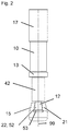
- FIGS. 1 to 4 show an embodiment of an inventive expansion anchor.
- the expansion anchor has an anchor bolt 10 with a longitudinal axis 99 and an expansion sleeve 30, wherein the expansion sleeve 30 surrounds the anchor bolt 10 in an annular manner.
- the anchor bolt 10 has a neck region 14 with at least approximately constant cross section. Following the neck region 14, the anchor bolt 10 in front of the neck region 14, in the front end region of the anchor bolt 10, an expansion body 15 for the expansion sleeve 30, which is here exemplified integrally with the rest of the anchor bolt 10.
- the anchor bolt 10 widens on its outer surface starting from the neck region 14 towards the front, that is to say the expansion body 15 converges on its outside toward the rear.
- the expansion sleeve 30 surrounds the neck region 14 of the anchor bolt 10.
- the expansion body 15 is arranged for the most part in front of the expansion sleeve 30.
- the anchor bolt 10 further includes a sleeve stopper 13, for example designed as a circular ring, which limits an axial movement of the expansion sleeve 30 towards the rear end of the anchor bolt 10, that is to say an axial movement of the expansion sleeve 30 away from the expansion body 15.
- a sleeve stopper 13 for example designed as a circular ring, which limits an axial movement of the expansion sleeve 30 towards the rear end of the anchor bolt 10, that is to say an axial movement of the expansion sleeve 30 away from the expansion body 15.
- the anchor bolt 10 has a load-engaging structure 17, here represented for example as an external thread, for introducing tensile forces into the anchor bolt 10.
- a nut On this external thread, a nut, not shown, may be arranged with a corresponding internal thread.
- the expansion sleeve 30 has expansion tongues 31 and anchor tongues 32, which are arranged on the front side of the expansion sleeve 30. Both the expansion tongues 31 and the anchor tongues 32 point axially forward.
- the expansion tongues 31 are a bit further forward as the anchor tongues 32, that is, the free Spreizzacheenden 33 are a bit far in front of the free anchor tongue ends 34. But also a flush arrangement or an arrangement in which the anchor tongues 32 further forward than the Spreizzache 31, is possible.
- Adjacent tongues 31, 32 are separated by slots 42 which, starting from the front end side of the expansion sleeve 30, which faces the expansion body 15, extend axially rearwardly into the expansion sleeve 30.
- the expansion tongues 31 and the anchor tongues 32 are free at their respective front and at their respective longitudinal sides and connected to each other at their respective rear sides.
- the armature tongues 32 each have a projection 36 which projects radially outwardly a small distance compared to the adjacent region of the respective armature tongue 32, and which is deflected radially by a bend of the free armature tongue end 34 of the respective armature tongue 32 outside is formed.
- Each of the projections 36 forms a radially outwardly facing claw of the respective anchor tongue 32.
- the projections 36 are given in particular in longitudinal section.
- the expansion tongues 31 on their outer side each have a step-shaped in longitudinal section, radially reaching into the expansion tongue 31 recess 35.
- the recess is open axially forward and backward through a shoulder of the limited expansion sprain, wherein the shoulder forms the riser of the stepped recess 35.
- Behind the recess 35 in the present embodiment on the radial outer side of the expansion sleeve 30 is still a radially extending into the expansion sleeve 30, extending in the circumferential direction groove 39 is provided.
- Sp St Dretti bevels 21 are formed on the expansion body 15 for the expansion tongues 31, which are arranged in front of the expansion tongues 31 axially. At this spreading bevels 21, the cross section of the anchor bolt 10 increases towards the front.
- the expansion bevels 21 can urge the expansion tongues 31 radially outwards when the anchor bolt 10 is displaced to the rear relative to the expansion sleeve 30 and the expansion tongues 31 accumulate on the expansion slopes 21.
- the spreading bevels 21 here form sections of a cone sheath.
- anchor slopes 22 are formed for the anchor tongues 32.
- the anchor slopes 22 may urge the anchor tongue 32 disposed in the associated trough 12 radially outward when the anchor bolt 10 is displaced rearwardly relative to the expansion sleeve 30 and the anchor tongues 32 thereby run onto the anchor slopes 22.
- the anchor slopes 22 are arranged in their respective rear portion 52 less steeply to the longitudinal axis 99 than in their respective front portion 53, that is, the anchor slopes 22 close with the longitudinal axis 99 of the anchor bolt 10 in their respective front portion 53 a larger maximum acute angle than
- the anchor slopes 22 in their respective front portion 53 are steeper to the longitudinal axis 99 than the Sp Schwarzschrägen 21, and arranged in their respective rear portion 52 less steeply to the longitudinal axis 99 than the Sp
- the expansion tongues 31 are initially primarily displaced radially. As the anchorage progresses, however, the anchor tongue 32 impinge on the steeper front region 53 of the respective armature bevel 22 and are then also reinforced radially displaced.
Abstract
Die Erfindung betrifft einen Spreizanker mit einer Spreizhülse (30) und einem Ankerbolzen (10) zum Spreizen der Spreizhülse (30) beim Versetzen des Ankerbolzens (10) relativ zur Spreizhülse (30) nach hinten, wobei die Spreizhülse (30) zumindest eine Spreizzunge (31) mit einem freien Spreizzungenende (33) und zumindest eine Ankerzunge (32) mit einem freien Ankerzungenende (34) aufweist, wobei das freie Spreizzungenende (33) und das freie Ankerzungenende (34) unterschiedlich konfiguriert sind.The invention relates to an expansion anchor with an expansion sleeve (30) and an anchor bolt (10) for spreading the expansion sleeve (30) when moving the anchor bolt (10) relative to the expansion sleeve (30) to the rear, wherein the expansion sleeve (30) at least one Spreizzunge (30). 31) with a free expansion end (33) and at least one anchor tongue (32) with a free anchor tongue end (34), wherein the free expansion end (33) and the free anchor tongue end (34) are configured differently.
Description
Die Erfindung betrifft einen Spreizanker gemäss dem Oberbegriff des Anspruchs 1. Ein solcher Spreizanker ist ausgestattet mit einer Spreizhülse und einem Ankerbolzen zum Spreizen der Spreizhülse beim Versetzen des Ankerbolzens relativ zur Spreizhülse nach hinten.The invention relates to an expansion anchor according to the preamble of claim 1. Such an expansion anchor is equipped with an expansion sleeve and an anchor bolt for spreading the expansion sleeve when moving the anchor bolt relative to the expansion sleeve to the rear.
Die
Die
Aus der
Die
Aufgabe der Erfindung ist es, einen Spreizanker anzugeben, der bei besonders geringem Herstellungsaufwand besonders leistungsfähig ist und besonders vielseitig einsetzbar ist.The object of the invention is to provide a spreader, which is particularly powerful at particularly low production costs and is particularly versatile.
Die Aufgabe wird erfindungsgemäss durch einen Spreizanker mit den Merkmalen des Anspruchs 1 gelöst. Bevorzugte Ausführungsformen sind in den abhängigen Ansprüchen angegeben.The object is achieved according to the invention by an expansion anchor with the features of claim 1. Preferred embodiments are given in the dependent claims.
Ein erfindungsgemässer Spreizanker ist dadurch gekennzeichnet, dass die Spreizhülse zumindest eine Spreizzunge mit einem freien Spreizzungenende und zumindest eine Ankerzunge mit einem freien Ankerzungenende aufweist, wobei das freie Spreizzungenende und das freie Ankerzungenende unterschiedlich konfiguriert sind.An expansion anchor according to the invention is characterized in that the expansion sleeve has at least one expansion tongue with a free spreader tongue end and at least one anchor tongue with a free anchor tongue end, wherein the free expansion end and the free anchor tongue end are configured differently.
Ein Grundgedanke der Erfindung kann darin gesehen werden, an derselben Spreizhülse unterschiedlich konfigurierte Zungen vorzusehen, wobei insbesondere die freien Enden der Zungen, die regelmässig zuerst an der umgebenden Bohrlochwand zur Anlage kommen, und die somit das Verankerungsverhalten massgeblich beeinflussen, unterschiedlich konfiguriert sind. Hierdurch können zusätzliche konstruktive Freiheitsgrade zur Verfügung gestellt werden, die es erlauben, die teilweise widersprüchlichen Anforderungen, die an die Spreizhülse gestellt werden, aufzulösen. Insbesondere können die Spreizzunge und die Ankerzunge jeweils für unterschiedliche Funktionsaufgaben optimiert werden. Beispielsweise kann die Spreizzunge für den Halt der Spreizhülse vor allem beim anfänglichen Spreizen durch den Ankerbolzen vorgesehen sein. Die Ankerzunge kann mit einer Verzögerung gespreizt werden - erst nachdem eine gewisse Verankerung durch erstes Anspreizen der Spreizzunge gewährleistet ist - um einen relativ grossen Hinterschnitt im Beton zu erzeugen. Dieser Hinterschnitt kann eine grössere äussere Reibungszahl bewirken. Durch Erhöhung von innerer und äusserer Reibung ist eine Erhöhung des maximalen Auszugwertes möglich. Darüber hinaus kann dadurch eine Hülsenverschiebung reduziert werden. Generell kann bei geringem Aufwand eine besonders leistungsfähiger und/oder vielseitig einsetzbarer Spreizanker erhalten werden.A basic idea of the invention can be seen to provide differently configured tongues on the same expansion sleeve, wherein in particular the free ends of the tongues, which regularly come into contact first with the surrounding borehole wall, and thus significantly influence the anchoring behavior, are configured differently. As a result, additional structural degrees of freedom can be made available, which allow to resolve the partially conflicting requirements that are placed on the expansion sleeve. In particular, the expansion tongue and the anchor tongue can each be optimized for different functional tasks. For example, the expansion tongue can be provided for the support of the expansion sleeve especially during the initial spreading by the anchor bolt. The anchor tongue can be spread with a delay - only after a certain anchoring is ensured by first spreading the spreading tongue - to produce a relatively large undercut in the concrete. This undercut can cause a larger external friction coefficient. Increasing internal and external friction makes it possible to increase the maximum pull-out value. In addition, this can be reduced sleeve displacement. In general, a particularly efficient and / or versatile expansion anchor can be obtained with little effort.
Unter dem freien Spreizzungenende kann wie bereits erwähnt insbesondere dasjenige Ende der Spreizzunge verstanden werden, das beim bestimmungsgemässen Betrieb an der umgebenden Bohrlochwand zu Anlage kommt. Ebenso kann unter dem freien Ankerzungenende wie bereits erwähnt insbesondere dasjenige Ende der Ankerzunge verstanden werden, das beim bestimmungsgemässen Betrieb an der umgebenden Bohrlochwand zu Anlage kommt. Das freie Spreizzungenende erstreckt sich vorteilhafterweise über eine axiale Länge von maximal 10%, 5% oder 2% der Gesamtlänge der Spreizzunge. Das freie Ankerzungenende erstreckt sich vorteilhafterweise über eine axiale Länge von maximal 10%, 5% oder 2% der Gesamtlänge der Ankerzunge. Ausser an den freien Enden können sich Spreizzunge und Ankerzunge auch in anderen Bereichen unterscheiden, müssen dies aber nicht.As already mentioned, in particular the end of the spreading tongue that comes to rest on the surrounding borehole wall during normal operation can be understood as the free spreader end. Likewise, as already mentioned, the free end of the tongue can be understood to mean, in particular, that end of the anchor tongue which comes into contact with the surrounding borehole wall during normal operation. The free Spreizzungenende advantageously extends over an axial length of a maximum of 10%, 5% or 2% of the total length of Spreizzunge. The free anchor tongue end advantageously extends over an axial length of at most 10%, 5% or 2% of the total length of the anchor tongue. Apart from the free ends, the expansion tongue and anchor tongue can also differ in other areas, but they do not have to.
Die Spreizhülse umgibt den Ankerbolzen. Die Spreizhülse bildet vorzugsweise einen offenen Ring, also eine C-Form, in dem beziehungsweise in der der Ankerbolzen aufgenommen ist, was eine einfache Herstellung durch Wickeln einer Platine um den Ankerbolzen ermöglicht.The expansion sleeve surrounds the anchor bolt. The expansion sleeve preferably forms an open ring, ie a C-shape, in which or in which the anchor bolt is accommodated, which allows a simple production by winding a board around the anchor bolt.
Der Ankerbolzen kann die Spreizzunge und die Ankerzunge radial verdrängen, wenn der Ankerbolzen relativ zur Spreizhülse axial nach hinten versetzt wird. Vorzugsweise können die Spreizhülse und der Ankerbolzen koaxial angeordnet sein.The anchor bolt can radially displace the expansion tongue and the anchor tongue when the anchor bolt is displaced axially rearward relative to the expansion sleeve. Preferably, the expansion sleeve and the anchor bolt can be arranged coaxially.
Der Ankerbolzen kann mehrteilig ausgeführt sein und beispielsweise aus einer Ankerstange und einem mit der Ankerstange verschraubten Spreizkörper bestehen, welcher für das Spreizen zumindest der Spreizzunge, vorzugsweise auch der Ankerzunge zuständig ist. Besonders bevorzugt ist es aber, dass der Ankerbolzen einstückig ausgebildet ist und dass insbesondere der Spreizkörper, welcher für das Spreizen zumindest der Spreizzunge, vorzugsweise auch der Ankerzunge zuständig ist, integral am Ankerbolzen angeordnet ist. In beiden Fäll ist der Spreizkörper zugfest am Ankerbolzen angeordnet, so dass über den Spreizkörper Zugkräfte auf die Spreizhülse übertragen werden können. Vorzugsweise bestehen die Spreizhülse und/oder der Ankerbolzen, insbesondere sein Spreizkörper, zumindest bereichsweise aus einem Metallmaterial. Insbesondere kann der Spreizkörper als Spreizkonus ausgebildet sein.The anchor bolt can be made in several parts and consist for example of an anchor rod and a bolted to the anchor rod spreader, which is responsible for spreading at least the expansion tongue, preferably also the anchor tongue. But it is particularly preferred that the anchor bolt is integrally formed and that in particular the spreader, which is responsible for spreading at least the expansion tongue, preferably also the anchor tongue, is integrally disposed on the anchor bolt. In both cases, the expansion body is arranged tensile strength on the anchor bolt so that tensile forces can be transmitted to the expansion sleeve via the expansion body. Preferably, the expansion sleeve and / or the anchor bolt, in particular its expansion body, at least partially made of a metal material. In particular, the expansion body may be formed as an expansion cone.
In einem rückwärtigen Bereich des Ankerbolzens kann der Ankerbolzen eine Lastangriffsstruktur aufweisen. Die Lastangriffsstruktur dient zum Einleiten von Zugkräften in den Ankerbolzen. Die Lastangriffsstruktur kann beispielsweise ein Aussengewinde oder ein Innengewinde sein. In einer anderen Ausgestaltung kann die Lastangriffsstruktur auch ein Kopf sein, der ein Querschnittsmaximum bildet.In a rearward region of the anchor bolt, the anchor bolt may have a load engagement structure. The load application structure serves to introduce tensile forces in the anchor bolts. The load application structure may be, for example, an external thread or an internal thread. In another embodiment, the load application structure may also be a head that forms a cross-sectional maximum.
Soweit nicht anders angegeben sollen die hier beschriebenen Merkmale insbesondere für einen nicht-montierten Spreizanker, also einen Spreizanker vor der Montage, gelten, und/oder für einen Zustand, in dem die Zungen noch nicht vom Ankerbolzen gespreizt sind.Unless otherwise stated, the features described herein are intended to apply in particular to a non-assembled expansion anchor, ie an expansion anchor prior to assembly, and / or for a condition in which the tongues have not yet been spread by the anchor bolt.
Soweit hiervon der Axialrichtung, der Umfangsrichtung und der Radialrichtung die Rede ist, soll sich dies insbesondere auf die Längsachse des Ankerbolzens beziehen, welche insbesondere mit der Längsachse des Spreizankers zusammenfallen kann. Auch die verschiedenen Neigungswinkel sollen sich insbesondere auf die Längsachse des Ankerbolzens beziehen. Die Längsachse des Ankerbolzens verläuft insbesondere in Montagerichtung, also in der Richtung, in welche der Ankerbolzen bei bestimmungsgemässer Montage in ein Bohrloch eingeschoben wird. Die Richtungsangaben "vorne" und "hinten" beziehungsweise "rückwärtig" sollen hier einheitlich verwendet werden, dies insbesondere soweit diese Richtungsangaben im Zusammenhang mit dem Ankerbolzen und der Spreizhülse verwendet werden. Insbesondere sollen sich die Richtungsangaben auf die Axialrichtung beziehen.As far as the axial direction, the circumferential direction and the radial direction is mentioned, this should refer in particular to the longitudinal axis of the anchor bolt, which may in particular coincide with the longitudinal axis of the expansion anchor. The various angles of inclination should also relate in particular to the longitudinal axis of the anchor bolt. The longitudinal axis of the anchor bolt extends in particular in the mounting direction, ie in the direction in which the anchor bolt is inserted when properly installed in a borehole. The directional indications "front" and "rear" or "rearward" are to be used uniformly here, in particular as far as these directions are used in connection with the anchor bolt and the expansion sleeve. In particular, the directions should refer to the axial direction.
Vorteilhafterweise sind das freie Spreizzungenende und das freie Ankerzungenende auf der radialen Aussenseite der Spreizhülse unterschiedlich konfiguriert. Da auf der radialen Aussenseite der Spreizhülse der Kontakt mit der Bohrlochwand stattfindet, kann bei einer hülsenaussenseitigen Anordnung die unterschiedliche Konfiguration besonders gut wirken.Advantageously, the free Spreizzungenende and the free anchor tongue end on the radial outer side of the expansion sleeve are configured differently. Since the contact with the borehole wall takes place on the radial outer side of the expansion sleeve, the different configuration can be particularly effective in the case of a sleeve-outside arrangement.
Besonders bevorzugt ist es, dass das freie Spreizzungenende und das freie Ankerzungenende, vorzugsweise zumindest auf der radialen Aussenseite der Spreizhülse, unterschiedliche Formen aufweisen, vorzugsweise unterschiedliche Längsschnittsformen. Die unterschiedliche Konfiguration der Zungen beinhaltet demgemäss unterschiedliche Geometrien, insbesondere auf der radialen Aussenseite der Spreizhülse. Dies kann die Herstellung noch weiter vereinfachen. Insbesondere können unterschiedliche Längsschnittsformen vorgesehen sein, also Formen in Längsschnittsebenen, wobei unter einer Längsschnittsebene in fachüblicher Weise eine Ebene verstanden werden kann, welche die Längsachse enthält.It is particularly preferred that the free Spreizzungenende and the free anchor tongue end, preferably at least on the radial outer side of the expansion sleeve, have different shapes, preferably different longitudinal sectional shapes. The different configuration of the tongues accordingly includes different geometries, in particular on the radial outer side of the expansion sleeve. This can further simplify the production. In particular, different longitudinal sectional shapes can be provided, that is to say forms in longitudinal sectional planes, wherein a longitudinal sectional plane can be understood in the usual manner as a plane which contains the longitudinal axis.
Zweckmässigerweise springt am freien Ankerzungenende die radiale Aussenseite der Spreizhülse radial nach aussen, also vom Ankerbolzen und/oder seiner Längsachse hinweg, vor. Insbesondere springt am freien Ankerzungenende die radiale Aussenseite der Spreizhülse gegenüber weiter hinten liegenden Bereichen der Ankerzunge radial nach aussen vor. Am freien Ankerzungenende ist also ein radial nach aussen vorstehender Vorsprung gebildet. Hierdurch kann in herstellungstechnisch besonders einfacher Art und Weise eine besonders wirksame Reibungserhöhung, vorzugsweise unter Hinterschnittbildung, an der Ankerzunge ermöglicht werden. Insbesondere kann die Ankerzunge an ihrem freien Ankerzungenende eine radial nach aussen gekrümmte Kralle bilden.Conveniently, the radial outer side of the expansion sleeve jumps radially outwards at the free end of the armature tongue, ie away from the anchor bolt and / or its longitudinal axis. In particular, at the free end of the armature tongue, the radial outer side of the expansion sleeve projects radially outwards in relation to areas of the armature tongue lying further back. At the free anchor tongue end so a radially outwardly projecting projection is formed. As a result, a particularly effective increase in friction, preferably undercut formation, on the anchor tongue can be made possible in manufacturing technology particularly simple manner. In particular, the anchor tongue can form a radially outwardly curved claw at its free anchor tongue end.
Es kann auch vorgesehen werden, dass am freien Spreizzungenende die radiale Aussenseite der Spreizhülse, vorzugsweise stufenartig, radial nach innen, also zum Ankerbolzen und/oder seiner Längsachse hin, zurückversetzt ist. Insbesondere ist am freien Spreizzungenende die radiale Aussenseite der Spreizhülse gegenüber weiter hinten liegenden Bereichen der Spreizzunge, vorzugsweise stufenartig, radial nach innen zurückversetzt. Am freien Spreizzungenende ist somit hülsenaussenseitig eine radiale Vertiefung vorgesehen. Insbesondere kann am freien Spreizzungenende eine Stufenstruktur, welche die Längsachse umgibt, und/oder eine Schulter, welche die Längsachse umgibt, vorgesehen werden. Hierdurch kann in herstellungstechnisch besonders einfacher Art und Weise eine besonders günstige Interaktion der Spreizhülse mit der umgebenden Bohrlochwand erzielt werden. Insbesondere kann die Vertiefung im Längsschnitt stufenförmig und/oder nach vorne hin offen sein.It can also be provided that the radial outer side of the expansion sleeve, preferably in a stepped manner, is set back radially inward, ie towards the anchor bolt and / or its longitudinal axis, at the free end of the expansion. In particular, at the free Spreizzungenende the radial outer side of the expansion sleeve opposite back further areas of the expansion tongue, preferably stepwise, set back radially inwards. At the free Spreizzungenende a radial recess is thus provided on the sleeve outer side. In particular, a step structure which surrounds the longitudinal axis and / or a shoulder which surrounds the longitudinal axis can be provided at the free expansion end. As a result, a particularly favorable interaction of the expansion sleeve with the surrounding borehole wall can be achieved in manufacturing technology particularly simple manner. In particular, the depression can be open in a longitudinal section in a stepped manner and / or towards the front.
Unter der radialen Aussenseite der Spreizhülse kann in fachüblicher Weise insbesondere die Seite der Spreizhülse verstanden werden, welche dem Ankerbolzen abgewandt ist und/oder die Seite der Spreizhülse, welche die aussenliegende Mantelfläche der Spreizhülse bildet.Under the radial outer side of the expansion sleeve can be understood in the usual way, in particular the side of the expansion sleeve, which faces away from the anchor bolt and / or the side of the expansion sleeve, which forms the outer circumferential surface of the expansion sleeve.
Die Spreizzunge und die Ankerzunge können in dieselbe Richtung zeigen, insbesondere entweder beide nach vorne oder beide nach hinten. Dies soll insbesondere beinhalten, dass entweder das freie Spreizzungenende vorne an der Spreizzunge und das freie Ankerzungenende vorne an der Ankerzunge angeordnet ist, oder das freie Spreizzungenende hinten an der Spreizzunge und das freie Ankerzungenende hinten an der Ankerzunge angeordnet ist. Insbesondere kann somit die Biegerichtung der beiden Zungen beim radialen Verdrängen dieselbe sein. Dies kann unter anderem im Hinblick auf den Kraftfluss vorteilhaft sein und/oder den Herstellungsaufwand weiter verringern.The spreader tongue and the anchor tongue may point in the same direction, especially either both forward or both backward. This should in particular include that either the free Spreizzungenende front of the expansion tongue and the free anchor tongue end is located on the front of the anchor tongue, or the free Spreizzungenende rear of the expansion tongue and the free anchor tongue end is located behind the anchor tongue. In particular, thus, the bending direction of the two tongues during radial displacement can be the same. This can be advantageous, inter alia, with regard to the flow of force and / or further reduce the production outlay.
Besonders bevorzugt ist es, dass sowohl die Spreizzunge als auch die Ankerzunge nach vorne zeigen, was insbesondere beinhalten kann, dass das freie Spreizzungenende vorne an der Spreizzunge und das freie Ankerzungenende vorne an der Ankerzunge angeordnet ist. Dies kann im Hinblick auf das Spreizverhalten vorteilhaft sein.It is particularly preferred that both the expansion tongue and the anchor tongue pointing forward, which may in particular include that the free Spreizzungenende front of the expansion tongue and the free anchor tongue end is located on the front of the anchor tongue. This can be advantageous in terms of spreading behavior.
Vorzugsweise stehen sowohl die Spreizzunge als auch die Ankerzunge vorne an der Spreizhülse vor. Insbesondere bilden somit das freie Spreizzungenende und das freie Ankerzungenende zumindest einen Abschnitt der vorderen Stirnseite der Spreizhülse. Bei einer solchen Ausgestaltung kann der Herstellungsaufwand besonders gering sein, insbesondere weil sowohl die Spreizzunge als auch die Ankerzunge durch Schlitze gebildet werden können, welche sich von der Stirnseite der Spreizhülse axial nach hinten in die Spreizhülse erstrecken. Darüber hinaus kann bei einer vorderseitigen Anordnung sowohl der Spreizzunge als auch der Ankerzunge eine besonders tiefe Lasteinleitung in das Bohrloch ermöglicht werden, was im Hinblick auf die Lastwerte vorteilhaft sein kann. Insbesondere kann eine Ausgestaltung vorgesehen sein, bei der die Spreizzunge und die Ankerzunge in Umfangsrichtung um die Längsachse nebeneinander angeordnet sind.Preferably, both the expansion tongue and the anchor tongue project forward on the expansion sleeve. In particular, thus form the free Spreizzungenende and the free anchor tongue end at least a portion of the front end of the expansion sleeve. In such an embodiment, the production cost can be particularly low, especially because both the Spreizzunge and the anchor tongue can be formed by slots extending axially from the end face of the expansion sleeve in the expansion sleeve. In addition, with a front-side arrangement of both the expansion tongue and the anchor tongue, a particularly deep load introduction into the borehole can be made possible, which may be advantageous with regard to the load values. In particular, an embodiment may be provided in which the expansion tongue and the anchor tongue are arranged in the circumferential direction about the longitudinal axis next to each other.
Die Spreizzunge und die Ankerzunge können mit ihren freien Enden auf derselben axialen Höhe enden, das heisst die freien Enden der beiden Zungen können axial nebeneinanderliegen. Dies kann herstellungstechnische Vorteile haben. Besonders bevorzugt kann es aber sein, dass die Spreizzunge und die Ankerzunge unterschiedlich weit nach vorne vorstehen. Insbesondere kann die Spreizzunge weiter nach vorne reichen als die Ankerzunge. Hierdurch kann das Verhalten des Spreizankers in konstruktiv besonders einfacher Weise noch besser an seine Umgebung angepasst werden.The expansion tongue and the anchor tongue can end with their free ends at the same axial height, that is, the free ends of the two tongues can be axially adjacent. This can have manufacturing advantages. However, it may be particularly preferred that the expansion tongue and the anchor tongue protrude differently far forwards. In particular, the spreader tongue can extend further forward than the anchor tongue. As a result, the behavior of the expansion anchor in a structurally particularly simple way can be better adapted to its environment.
Besonders bevorzugt ist es, dass der Ankerbolzen eine nach hinten weisende Spreizschräge zum radialen Verdrängen der Spreizzunge und eine nach hinten weisende Ankerschräge zum radialen Verdrängen der Ankerzunge aufweist.It is particularly preferred that the anchor bolt has a rearwardly pointing expansion bevel for radially displacing the expansion tongue and a rearwardly facing anchor slope for radially displacing the anchor tongue.
Vorzugsweise verläuft die Ankerschräge zumindest bereichsweise steiler als die Spreizschräge. Die beiden Zungen sind also nicht nur verschieden konfiguriert, sondern werden vom Ankerbolzen auch mit unterschiedlichen Spreizwinkeln gespreizt. Hierdurch kann das Ankerverhalten noch weiter verbessert werden. Unter der zumindest bereichsweise "steileren" Anordnung der Ankerschräge verglichen mit der Spreizschräge soll insbesondere verstanden werden, dass die Ankerschräge zumindest bereichsweise einen grösseren spitzen Neigungswinkel zur Längsachse des Ankerbolzens aufweist als die Spreizschräge, dies gemessen insbesondere in einer die Längsachse des Ankerbolzens enthaltenden Längsschnittsebene. "Steiler" soll also insbesondere "bezogen auf die Längsachse steiler" beinhalten.Preferably, the anchor slope is at least partially steeper than the expansion slope. The two tongues are not only configured differently, but are spread by the anchor bolt with different spread angles. As a result, the anchor behavior can be further improved. The at least partially "steeper" arrangement of the armature bevel compared to the expansion be understood in particular that the anchor slope at least partially has a greater acute angle to the longitudinal axis of the anchor bolt than the expansion bevel, this measured in particular in a longitudinal axis of the anchor bolt containing longitudinal section plane. "Steeper" should therefore in particular "steeper relative to the longitudinal axis" include.
Insbesondere sind die Spreizschräge und die Ankerschräge zugfest am Ankerbolzen angeordnet, so dass nach hinten gerichtete Zugkräfte über diese Schrägen vom Ankerbolzen an die Zungen übertragen werden können. Insbesondere zeigt die Spreizzunge zur Spreizschräge und die Ankerzunge zur Ankerschräge. Die Spreizschräge ist insbesondere zumindest bereichsweise vor der Spreizzunge angeordnet. Die Ankerschräge ist insbesondere zumindest bereichsweise vor der Ankerzunge angeordnet.In particular, the expansion bevel and the anchor slope are arranged tensile strength on the anchor bolt, so that backward tensile forces can be transmitted via these bevels from the anchor bolt to the tongues. In particular, the spreading tongue for spreading slope and the anchor tongue to the anchor slope. The spreading bevel is in particular arranged at least in some areas in front of the expansion tongue. The anchor slope is arranged in particular at least partially in front of the anchor tongue.
Der Ankerbolzen kann die beiden Zungen mit seinen Schrägen radial verdrängen, wenn der Ankerbolzen relativ zur Spreizhülse axial nach hinten versetzt wird. Insbesondere dient die Spreizschräge zum radialen Verdrängen der Spreizzunge beim axialen Versetzen der Spreizschräge relativ zur Spreizzunge nach hinten und dient die Ankerschräge zum radialen Verdrängen der Ankerzunge beim axialen Versetzen der Ankerschräge relativ zur Ankerzunge nach hinten.The anchor bolt can displace the two tongues with its bevels radially when the anchor bolt is offset axially to the rear relative to the expansion sleeve. In particular, the expansion bevel serves for the radial displacement of the expansion tongue in the axial displacement of the expansion bevel relative to the expansion tongue to the rear and serves the anchor slope for radial displacement of the anchor tongue in the axial displacement of the anchor slope relative to the anchor tongue to the rear.
Die beiden Schrägen weisen beide nach hinten, insbesondere bezogen auf die Längsachse des Ankerbolzens, was insbesondere beinhalten kann, dass der Ankerbolzen hinter den beiden Schrägen jeweils einen Freiraum aufweist. Insbesondere nähern sich sowohl die Spreizschräge als auch die Ankerschräge nach hinten hin an die Längsachse des Ankerbolzens an.The two bevels both point to the rear, in particular with respect to the longitudinal axis of the anchor bolt, which may in particular include that the anchor bolt behind the two slopes each have a free space. In particular, both the expansion slope and the anchor slope approach towards the rear to the longitudinal axis of the anchor bolt.
Insbesondere kann die Ankerschräge einen maximalen Neigungswinkel mit der Längsachse aufweisen, der im Bereich von 36° bis 70° liegt. Dies ermöglicht eine besonders gute Verankerung. Die Spreizschräge kann beispielsweise einen maximalen Neigungswinkel mit der Längsachse von etwa 30° aufweisen.In particular, the anchor slope may have a maximum angle of inclination with the longitudinal axis, which is in the range of 36 ° to 70 °. This allows a particularly good anchorage. The spreading bevel may for example have a maximum angle of inclination with the longitudinal axis of about 30 °.
Insbesondere kann vorgesehen werden, dass die Ankerschräge in einem hinteren Bereich der Ankerschräge weniger steil verläuft als in einem vorderen Bereich der Ankerschräge. Besonders bevorzugt ist es, dass die Ankerschräge in einem hinteren Bereich der Ankerschräge weniger steil verläuft als die Spreizschräge, und dass die Ankerschräge in einem vorderen Bereich der Ankerschräge steiler verläuft als die Spreizschräge. Hierdurch kann in besonders einfacher Art und Weise erreicht werden, dass bei geringer Belastung im Ankerbolzen zunächst die Spreizzunge aktiviert wird, und die Ankerzunge erst bei höherer Belastung aktiviert wird, dies dann aber besonders intensiv für eine besonders gute Verankerung. Die Ankerzunge wird beim rückwärtigen Versetzen des Ankerbolzens relativ zur Spreizhülse also anfangs weniger weit radial verdrängt als die Spreizzunge. Bei fortgeschrittener rückwärtiger Verschiebung des Ankerbolzens relativ zur Spreizhülse wird die Ankerzunge dann aber weiter radial verdrängt als die Spreizzunge, insbesondere unter Hinterschnittbildung an der Ankerzunge. Wie schon weiter oben angedeutet kann hierdurch ein besonders gutes Lastverhalten erreicht werden. Insbesondere kann die innere Reibung zu Beginn des Montagevorgangs besonders klein gehalten werden, was einem unerwünschten frühen Ausziehen des Spreizankers besonders effizient entgegenwirken kann.In particular, it can be provided that the anchor slope in a rear region of the anchor slope is less steep than in a front region of the anchor slope. It is particularly preferred that the anchor slope in a rear region of the anchor slope is less steep than the expansion slope, and that the anchor slope in a front region of the anchor slope is steeper than the spreading slope. This can be achieved in a particularly simple manner that at low load in the anchor bolt first the spreading tongue is activated, and the anchor tongue is activated only at higher load, but this then particularly intense for a particularly good anchorage. The anchor tongue is thus initially less far radially displaced when the rearward displacement of the anchor bolt relative to the expansion sleeve than the expansion tongue. In the case of advanced rearward displacement of the anchor bolt relative to the expansion sleeve, the anchor tongue is then displaced further radially than the expansion tongue, in particular undercut formation on the anchor tongue. As already indicated above, this allows a particularly good load behavior to be achieved. In particular, the internal friction at the beginning of the assembly process can be kept particularly small, which can counteract an undesirable early extraction of the expansion anchor particularly efficient.
Vorzugsweise deckt die Ankerschräge das freie Ende der Ankerzunge, in Umfangsrichtung des Ankerbolzens betrachtet, komplett ab. Mit anderen Worten ist der Winkelbereich, den die Ankerschräge um die Längsachse des Ankerbolzens überspannt, gleich gross oder grösser als der Winkelbereich, den das freie Ende der Ankerzunge um die Längsachse des Ankerbolzens überspannt, und der Winkelbereich, den das freie Ende der Ankerzunge um die Längsachse des Ankerbolzens überspannt, liegt innerhalb des Winkelbereichs, den die Ankerschräge um die Längsachse des Ankerbolzens überspannt. Hierdurch kann die Ankerzunge besonders wirkungsvoll aktiviert werden.Preferably, the anchor slope completely covers the free end of the anchor tongue, viewed in the circumferential direction of the anchor bolt. In other words, the angular range, which spans the anchor slope about the longitudinal axis of the anchor bolt, is equal to or greater than the angular range, which spans the free end of the anchor tongue about the longitudinal axis of the anchor bolt, and the angular range, the free end of the anchor tongue to the Spanned over the longitudinal axis of the anchor bolt, is within the angular range, which spans the anchor ramp about the longitudinal axis of the anchor bolt. As a result, the anchor tongue can be activated particularly effectively.
Eine weitere bevorzugte Ausgestaltung der Erfindung liegt darin, dass die Ankerschräge an einer im Ankerbolzen angeordneten Mulde gebildet ist. Diese Mulde erstreckt sich radial in den Ankerbolzen hinein. Der Boden der Mulde kann den hinteren Bereich der Ankerschräge und eine die Mulde vorderseitig begrenzende Wand kann den vorderen Bereich der Ankerschräge bilden. Diese Ausgestaltung erlaubt eine besonders einfache Herstellung eines erfindungsgemässen Spreizankers. Die Mulde kann vorzugsweise im gegebenenfalls vorhandenen Spreizkörper des Ankerbolzens angeordnet sein.A further preferred embodiment of the invention is that the anchor slope is formed on a trough arranged in the anchor bolt. This trough extends radially into the anchor bolt. The bottom of the trough may be the rear portion of the anchor slope and a front wall delimiting the trough may form the forward portion of the anchor slope. This embodiment allows a particularly simple production of an inventive Expansion anchor. The trough can preferably be arranged in the possibly present expansion body of the anchor bolt.
Es kann vorgesehen werden, dass sich die Ankerschräge und die Spreizschräge axial überlappen. Zweckmässigerweise weist der Ankerbolzen, wie schon weiter oben angedeutet, einen Spreizkörper auf, wobei zumindest die Spreizschräge, vorzugsweise sowohl die Ankerschräge als auch die Spreizschräge, am Spreizkörper gebildet ist. Dies kann unter anderem herstellungstechnische Vorteile haben und für eine besonders konzentrierte Lasteinleitung, insbesondere tief im Bohrloch, sorgen. Der Spreizkörper kann vorzugsweise einstückig mit dem Rest des Ankerbolzens, insbesondere einstückig mit einer Ankerstange des Ankerbolzens, ausgeführt sein. Grundsätzlich könnte der Spreizkörper auch getrennt von der Ankerstange ausgeführt sein, dann aber zugfest mit der Ankerstange gekoppelt. Der Spreizkörper kann insbesondere ein Spreizkonus sein.It can be provided that the anchor slope and the expansion slope overlap axially. Conveniently, the anchor bolt, as already indicated above, on an expansion body, wherein at least the expansion bevel, preferably both the anchor slope and the expansion bevel, is formed on the expansion body. Among other things, this can have manufacturing advantages and provide for a particularly concentrated load introduction, in particular deep in the borehole. The expansion body can preferably be made in one piece with the rest of the anchor bolt, in particular in one piece with an anchor rod of the anchor bolt. In principle, the spreader could also be carried out separately from the anchor rod, but then coupled tensile strength with the anchor rod. The expansion body may in particular be an expansion cone.
Es kann auch vorgesehen werden, dass die Spreizhülse mehrere Spreizzungen und/oder mehrere Ankerzungen aufweist. Dies kann im Hinblick auf eine besonders homogene Krafteinleitung in die umgebende Bohrlochwand, auf die Vermeidung von Spannungsspitzen und somit auf besonders gute Lastwerte vorteilhaft sein. Soweit mehrere Spreizzungen und/oder mehrere Ankerzungen vorgesehen sind, können diese vorzugsweise so ausgebildet sein, wie es hier im Zusammenhang mit einer Spreizzunge beziehungsweise einer Ankerzunge beschrieben ist.It can also be provided that the expansion sleeve has a plurality of expansion tongues and / or a plurality of anchor tongues. This may be advantageous in view of a particularly homogeneous introduction of force into the surrounding borehole wall, to the avoidance of voltage peaks and thus to particularly good load values. As far as a plurality of expansion tongues and / or a plurality of anchor tongues are provided, these may preferably be formed as described herein in connection with a spreader tongue or an anchor tongue.
Die Erfindung betrifft auch die bestimmungsgemässe Verwendung eines erfindungsgemässen Spreizankers. Insbesondere betrifft die Erfindung die Verwendung eines erfindungsgemässen Spreizankers, bei welcher der Ankerbolzen relativ zur, insbesondere in einem Bohrloch angeordneten, Spreizhülse nach hinten versetzt wird, und dabei die Spreizzunge, vorzugsweise von der Spreizschräge, und die Ankerzunge, vorzugsweise von der Ankerschräge, radial verdrängt werden.The invention also relates to the intended use of an inventive expansion anchor. In particular, the invention relates to the use of an inventive expansion anchor, in which the anchor bolt is displaced relative to, in particular in a borehole, expansion sleeve is displaced to the rear, and thereby radially displaced the expansion tongue, preferably from the expansion slope, and the anchor tongue, preferably from the anchor slope become.
Besonders bevorzugt ist es, dass die Ankerzunge beim Versetzen des Ankerbolzens relativ zur Spreizhülse nach hinten anfangs weniger weit radial verdrängt wird als die Spreizzunge. Dies kann durch eine im rückwärtigen Bereich weniger steile Ausgestaltung der Ankerschräge verglichen mit der Spreizschräge erreicht werden. Später wird die Ankerzunge vorzugsweise weiter radial verdrängt als die Spreizzunge, was durch eine im vorderen Bereich steilere Ausgestaltung der Ankerschräge verglichen mit der Spreizschräge erreicht werden kann.It is particularly preferred that the armature tongue initially relatively less radially displaced during displacement of the anchor bolt relative to the expansion sleeve to the rear than the expansion tongue. This can be achieved by a less steep design in the rear region of the anchor slope compared to the expansion bevel. Later, the anchor tongue is preferably further displaced radially than the expansion tongue, which can be achieved by a steeper in the front region embodiment of the anchor slope compared with the expansion bevel.
Merkmale, die im Zusammenhang mit dem erfindungsgemässen Spreizanker erläutert werden, können auch bei der erfindungsgemässen Verwendung zum Einsatz kommen, so wie auch umgekehrt Merkmale, die im Zusammenhang mit der erfindungsgemässen Verwendung erläutert werden, auch beim erfindungsgemässen Spreizanker zum Einsatz kommen können.Features that are explained in connection with the inventive expansion anchor, can also be used in the inventive use, as well as vice versa features that are explained in connection with the inventive use, also in the inventive expansion anchor can be used.
Die Erfindung wird nachfolgend anhand bevorzugter Ausführungsbeispiele näher erläutert, die schematisch in den beiliegenden Figuren dargestellt sind, wobei einzelne Merkmale der nachfolgend gezeigten Ausführungsbeispiele im Rahmen der Erfindung grundsätzlich einzeln oder in beliebiger Kombination realisiert werden können. In den Figuren zeigen schematisch:
- Figur 1:
- eine Seitenansicht einer ersten Ausführungsform eines erfindungsgemässen Spreizankers;
- Figur 2:
- eine Seitenansicht des Ankerbolzens des Spreizankers aus
Figur 1 ohne Spreizhülse; - Figur 3:
- eine Seitenansicht der Spreizhülse des Spreizankers aus
Figur 1 ; und - Figur 4:
- eine Längsschnittansicht des Spreizankers aus
Figur 1 .
- FIG. 1:
- a side view of a first embodiment of an inventive expansion anchor;
- FIG. 2:
- a side view of the anchor bolt of the expansion anchor
FIG. 1 without expansion sleeve; - FIG. 3:
- a side view of the expansion of the expansion anchor
FIG. 1 ; and - FIG. 4:
- a longitudinal sectional view of the expansion anchor
FIG. 1 ,
Die
Der Ankerbolzen 10 weist ferner einen beispielsweise als Kreisring ausgebildeten Hülsenanschlag 13 auf, der eine Axialbewegung der Spreizhülse 30 zum rückwärtigen Ende des Ankerbolzens 10 hin, das heisst eine Axialbewegung der Spreizhülse 30 vom Spreizkörper 15 hinweg, begrenzt.The
An seinem dem Spreizkörper 15 entgegengesetzten rückwärtigen Endbereich weist der Ankerbolzen 10 eine, hier beispielsweise als Aussengewinde dargestellte, Lastangriffsstruktur 17 zum Einleiten von Zugkräften in den Ankerbolzen 10 auf. Auf diesem Aussengewinde kann eine nicht dargestellte Mutter mit korrespondierendem Innengewinde angeordnet sein.At its rear end region opposite the
Wie insbesondere
In der vorliegenden Ausgestaltung folgt in Umfangsrichtung auf eine Spreizzunge 31 eine Ankerzunge 32, dann wieder eine Spreizzunge 31, und so weiter, das heisst es liegt eine alternierende Anordnung vor. Aber auch andere Ausgestaltungen sind denkbar. Benachbarte Zungen 31, 32 werden durch Schlitze 42 getrennt, die sich ausgehend von der vorderen Stirnseite der Spreizhülse 30, die dem Spreizkörper 15 zugewandt ist, axial nach hinten in die Spreizhülse 30 hinein erstrecken.In the present embodiment follows in the circumferential direction of a spreading
Die Spreizzungen 31 und die Ankerzungen 32 sind an ihrer jeweiligen Vorderseite und an ihren jeweiligen Längsseiten frei und an ihren jeweiligen Rückseiten miteinander verbunden.The
Am jeweiligen freien Ankerzungenende 34 weisen die Ankerzungen 32 jeweils einen Vorsprung 36 auf, der - verglichen mit dem benachbarten Bereich der jeweiligen Ankerzunge 32 - ein kleines Stück radial nach aussen vorsteht, und der durch eine Umbiegung des freien Ankerzungenendes 34 der jeweiligen Ankerzunge 32 radial nach aussen hin gebildet ist. Jeder der Vorsprünge 36 bildet eine radial nach aussen weisende Kralle der jeweiligen Ankerzunge 32. Die Vorsprünge 36 sind insbesondere im Längsschnitt gegeben.At the respective free
Am jeweiligen freien Spreizzungenende 33 weisen die Spreizzungen 31 an ihrer Aussenseite jeweils eine im Längsschnitt stufenförmige, radial in die Spreizzunge 31 reichende Vertiefung 35 auf. Die Vertiefung ist axial nach vorne hin offen und rückwärtig durch eine Schulter der jeweiligen Spreizzunge begrenzt, wobei die Schulter die Setzstufe der stufenförmigen Vertiefung 35 bildet. Hinter der Vertiefung 35 ist in der vorliegenden Ausgestaltung auf der radialen Aussenseite der Spreizhülse 30 noch eine radial in die Spreizhülse 30 reichende, in Umfangsrichtung verlaufende Nut 39 vorgesehen.At the respective
Am Spreizkörper 15 sind Spreizschrägen 21 für die Spreizzungen 31 gebildet, welche den Spreizzungen 31 axial vorgelagert sind. An diesen Spreizschrägen 21 nimmt der Querschnitt des Ankerbolzens 10 nach vorne hin zu. Die Spreizschrägen 21 können die Spreizzungen 31 radial nach aussen drängen, wenn der Ankerbolzen 10 relativ zur Spreizhülse 30 nach hinten versetzt wird und die Spreizzungen 31 dabei auf die Spreizschrägen 21 auflaufen. Die Spreizschrägen 21 bilden hier Abschnitte eines Kegelmantels.Spreiz bevels 21 are formed on the
Im Spreizkörper 15 des Ankerbolzens 10 sind Mulden 12 gebildet, die sich radial nach innen zur Längsachse 99 des Ankerbolzens 10 erstreckt. In diesen Mulden 12 sind Ankerschrägen 22 für die Ankerzungen 32 gebildet. An diesen Ankerschrägen 22 nimmt der Querschnitt des Ankerbolzens 10 nach vorne hin zu. Die Ankerschrägen 22 können die in der zugeordneten Mulde 12 angeordnete Ankerzunge 32 radial nach aussen drängen, wenn der Ankerbolzen 10 relativ zur Spreizhülse 30 nach hinten versetzt wird und die Ankerzungen 32 dabei auf die Ankerschrägen 22 auflaufen.In the
Die Ankerschrägen 22 sind in ihrem jeweils hinteren Bereich 52 weniger steil zur Längsachse 99 angeordnet als in ihrem jeweils vorderen Bereich 53, das heisst die Ankerschrägen 22 schliessen mit der Längsachse 99 des Ankerbolzens 10 in ihrem jeweils vorderen Bereich 53 einen grösseren maximalen spitzen Winkel ein als in ihrem jeweils hinteren Bereich 52. Insbesondere sind die die Ankerschrägen 22 in ihrem jeweils vorderen Bereich 53 steiler zur Längsachse 99 angeordnet als die Spreizschrägen 21, und in ihrem jeweils hinteren Bereich 52 weniger steil zur Längsachse 99 angeordnet als die Spreizschrägen 21.The anchor slopes 22 are arranged in their respective rear portion 52 less steeply to the
Beim Montieren des Spreizankers wird der Ankerbolzen 10 mit seinem vorderen Ende voran in Richtung der Längsachse 99 des Ankerbolzens 10 in ein Bohrloch geschoben. Aufgrund des Hülsenanschlags 13, der eine Verschiebung der Spreizhülse 30 zum hinteren Ende des Ankerbolzens 10 blockiert, wird dabei auch die Spreizhülse 30 in das Bohrloch eingebracht. Sodann wird der Ankerbolzen 10, beispielsweise durch Anziehen einer Mutter, die auf der als Aussengewinde ausgebildeten Lastangriffsstruktur 17 angeordnet ist, wieder ein Stück weit aus dem Bohrloch herausgezogen. Aufgrund ihrer Reibung mit der Bohrlochwand bleibt die Spreizhülse 30 dabei zurück und es kommt zu einer axialen Verschiebung des Ankerbolzens 10 relativ zur Spreizhülse 30 nach hinten. Im Verlauf dieser Verschiebung laufen die Spreizzungen 31 auf ihre Spreizschrägen 21 auf und werden von diesen radial gegen die Bohrlochwand nach aussen gedrängt, und die Ankerzungen 32 laufen auf ihre Ankerschrägen 22 auf und werden von diesen radial gegen die Bohrlochwand nach aussen gedrängt. Durch diesen Mechanismus wird der Spreizanker im Substrat fixiert.When mounting the expansion anchor of the
Da die Ankerschrägen 22 hinten weniger steil sind als die Spreizschrägen 21, werden zunächst vorrangig die Spreizzungen 31 radial verdrängt. Bei fortschreitender Verankerung treffen die Ankerzunge 32 jedoch auf den steileren vorderen Bereich 53 der jeweiligen Ankerschräge 22 und werden dann ebenfalls verstärkt radial verdrängt.Since the anchor slopes 22 at the rear are less steep than the spreading
Claims (14)
dadurch gekennzeichnet,
dass die Spreizhülse (30) zumindest eine Spreizzunge (31) mit einem freien Spreizzungenende (33) und zumindest eine Ankerzunge (32) mit einem freien Ankerzungenende (34) aufweist, wobei das freie Spreizzungenende (33) und das freie Ankerzungenende (34) unterschiedlich konfiguriert sind.Expansion anchor with an expansion sleeve (30) and an anchor bolt (10) for spreading the expansion sleeve (30) when moving the anchor bolt (10) relative to the expansion sleeve (30) to the rear,
characterized,
in that the expansion sleeve (30) has at least one expansion tongue (31) with a free expansion end (33) and at least one anchor tongue (32) with a free anchor tongue end (34), wherein the free expansion end (33) and the free anchor tongue end (34) differ are configured.
dadurch gekennzeichnet,
dass das freie Spreizzungenende (33) und das freie Ankerzungenende (34) auf der radialen Aussenseite der Spreizhülse (30) unterschiedlich konfiguriert sind.Expansion anchor according to claim 1,
characterized,
that the free Spreizzungenende (33) and the free end of the tongue anchor (34) on the radial outside of the expansion sleeve (30) are configured differently.
dadurch gekennzeichnet,
dass das freie Spreizzungenende (33) und das freie Ankerzungenende (34) unterschiedliche Längsschnittsformen aufweisen.Expansion anchor according to one of the preceding claims,
characterized,
in that the free expansion end (33) and the free insertion end (34) have different longitudinal sectional shapes.
dadurch gekennzeichnet,
dass am freien Ankerzungenende (34) die radiale Aussenseite der Spreizhülse (30) radial nach aussen vorspringt und/oder
dass am freien Spreizzungenende (33) die radiale Aussenseite der Spreizhülse (30) radial nach innen zurückversetzt ist.Expansion anchor according to one of the preceding claims,
characterized,
that at the free end of the tongue anchor (34), the radial outside of the expansion sleeve (30) projecting radially and / or outwardly
in that the radial outer side of the expansion sleeve (30) is recessed radially inward at the free expansion end (33).
dadurch gekennzeichnet,
dass sowohl die Spreizzunge (31) als auch die Ankerzunge (32) nach vorne zeigen.Expansion anchor according to one of the preceding claims,
characterized,
that both the expansion tongue (31) and the anchor tongue (32) point forwards.
dadurch gekennzeichnet,
dass sowohl die Spreizzunge (31) als auch die Ankerzunge (32) vorne an der Spreizhülse (30) vorstehen.Expansion anchor according to one of the preceding claims,
characterized,
in that both the expansion tongue (31) and the anchor tongue (32) project forward on the expansion sleeve (30).
dadurch gekennzeichnet,
dass die Spreizzunge (31) und die Ankerzunge (32) unterschiedlich weit nach vorne vorstehen.Expansion anchor according to one of the preceding claims,
characterized,
that the expansion tongue (31) and the anchor tongue (32) protrude differently far forward.
dadurch gekennzeichnet,
dass der Ankerbolzen (10) eine nach hinten weisende Spreizschräge (21) zum radialen Verdrängen der Spreizzunge (31) und eine nach hinten weisende Ankerschräge (22) zum radialen Verdrängen der Ankerzunge (32) aufweist, wobei die Ankerschräge (22) zumindest bereichsweise steiler verläuft als die Spreizschräge (21).Expansion anchor according to one of the preceding claims,
characterized,
in that the anchor bolt (10) has an expander slope (21) pointing to the rear for radial displacement of the expansion tongue (31) and an anchor slope (22) pointing towards the rear for radially displacing the anchor tongue (32), wherein the anchor slope (22) is steeper at least in places runs as the expansion bevel (21).
dadurch gekennzeichnet,
dass die Ankerschräge (22) in einem hinteren Bereich (52) der Ankerschräge (22) weniger steil verläuft als die Spreizschräge (21), und dass die Ankerschräge (22) in einem vorderen Bereich (53) der Ankerschräge steiler verläuft als die Spreizschräge (21).Expansion anchor according to claim 8,
characterized,
that the anchor slope (22) in a rear region (52) of the anchor slope (22) runs less steeply than the expansion slope (21), and that the anchor slope (22) in a front region (53) of the anchor slope is steeper than the expansion slope ( 21).
dadurch gekennzeichnet,
dass die Ankerschräge (22) an einer im Ankerbolzen (10) angeordneten Mulde (12) gebildet ist.Expansible anchor according to one of claims 8 or 9,
characterized,
that the anchor ramp (22) arranged on one in the anchor bolt (10) recess (12) is formed.
dadurch gekennzeichnet,
dass sich die Ankerschräge (22) und die Spreizschräge (21) axial überlappen.Expansible anchor according to one of claims 8 to 10,
characterized,
that the anchor slope (22) and the expansion slope (21) overlap axially.
dadurch gekennzeichnet,
dass der Ankerbolzen (10) einen Spreizkörper (15) aufweist, und dass zumindest die Spreizschräge (21) am Spreizkörper (15) gebildet ist.Expansion anchor according to one of claims 8 to 11,
characterized,
is that the anchor bolt (10) has an expansion body (15), and that at least the Spreizschräge (21) on the expansion body (15) is formed.
dadurch gekennzeichnet,
dass die Ankerzunge (32) beim Versetzen des Ankerbolzens (10) relativ zur Spreizhülse (30) nach hinten anfangs weniger weit und später weiter radial verdrängt wird als die Spreizzunge (31).Use according to claim 13,
characterized,
that the anchor tongue (32) when moving the anchor bolt (10) relative to the expansion sleeve (30) to the rear initially less far and later further radially displaced as the expansion tongue (31).
Priority Applications (2)
| Application Number | Priority Date | Filing Date | Title |
|---|---|---|---|
| EP18159869.9A EP3536986A1 (en) | 2018-03-05 | 2018-03-05 | Expansion anchor comprising expanding sleeve with different tongues |
| PCT/EP2019/054930 WO2019170505A1 (en) | 2018-03-05 | 2019-02-28 | Expansion anchor having expansion sleeve comprising differing tongues |
Applications Claiming Priority (1)
| Application Number | Priority Date | Filing Date | Title |
|---|---|---|---|
| EP18159869.9A EP3536986A1 (en) | 2018-03-05 | 2018-03-05 | Expansion anchor comprising expanding sleeve with different tongues |
Publications (1)
| Publication Number | Publication Date |
|---|---|
| EP3536986A1 true EP3536986A1 (en) | 2019-09-11 |
Family
ID=61563249
Family Applications (1)
| Application Number | Title | Priority Date | Filing Date |
|---|---|---|---|
| EP18159869.9A Withdrawn EP3536986A1 (en) | 2018-03-05 | 2018-03-05 | Expansion anchor comprising expanding sleeve with different tongues |
Country Status (2)
| Country | Link |
|---|---|
| EP (1) | EP3536986A1 (en) |
| WO (1) | WO2019170505A1 (en) |
Citations (9)
| Publication number | Priority date | Publication date | Assignee | Title |
|---|---|---|---|---|
| DE2256822A1 (en) | 1972-11-20 | 1974-06-06 | Manfred Dipl Ing Jost | ANCHORS, IN PARTICULAR DOWELS |
| DE2701510A1 (en) * | 1977-01-15 | 1978-07-20 | Upat Max Langensiepen Kg | Dowel with tapered plug for fixing objects to walls - is expanded radially by shank of bolt engaging internal ridge |
| EP0019782A2 (en) * | 1979-05-31 | 1980-12-10 | Albert Berner GmbH & Co KG | Metal-shell dowel |
| CH688061A5 (en) * | 1992-12-07 | 1997-04-30 | Mungo Befestigungstech Ag | Masonry fitting bolt for ceiling use |
| JP2007154914A (en) * | 2005-11-30 | 2007-06-21 | Nippon Eisei Center:Kk | Aseismatic expansion anchor |
| EP2309138A2 (en) | 2009-10-06 | 2011-04-13 | HILTI Aktiengesellschaft | Expansion anchor |
| WO2012126700A1 (en) | 2011-03-23 | 2012-09-27 | Hilti Aktiengesellschaft | Anchor bolt and production method |
| EP2848825A1 (en) | 2013-09-16 | 2015-03-18 | HILTI Aktiengesellschaft | Split anchor |
| WO2015067578A1 (en) | 2013-11-06 | 2015-05-14 | Hilti Aktiengesellschaft | Expansion anchor with grooves in the expansion cone |
-
2018
- 2018-03-05 EP EP18159869.9A patent/EP3536986A1/en not_active Withdrawn
-
2019
- 2019-02-28 WO PCT/EP2019/054930 patent/WO2019170505A1/en active Application Filing
Patent Citations (9)
| Publication number | Priority date | Publication date | Assignee | Title |
|---|---|---|---|---|
| DE2256822A1 (en) | 1972-11-20 | 1974-06-06 | Manfred Dipl Ing Jost | ANCHORS, IN PARTICULAR DOWELS |
| DE2701510A1 (en) * | 1977-01-15 | 1978-07-20 | Upat Max Langensiepen Kg | Dowel with tapered plug for fixing objects to walls - is expanded radially by shank of bolt engaging internal ridge |
| EP0019782A2 (en) * | 1979-05-31 | 1980-12-10 | Albert Berner GmbH & Co KG | Metal-shell dowel |
| CH688061A5 (en) * | 1992-12-07 | 1997-04-30 | Mungo Befestigungstech Ag | Masonry fitting bolt for ceiling use |
| JP2007154914A (en) * | 2005-11-30 | 2007-06-21 | Nippon Eisei Center:Kk | Aseismatic expansion anchor |
| EP2309138A2 (en) | 2009-10-06 | 2011-04-13 | HILTI Aktiengesellschaft | Expansion anchor |
| WO2012126700A1 (en) | 2011-03-23 | 2012-09-27 | Hilti Aktiengesellschaft | Anchor bolt and production method |
| EP2848825A1 (en) | 2013-09-16 | 2015-03-18 | HILTI Aktiengesellschaft | Split anchor |
| WO2015067578A1 (en) | 2013-11-06 | 2015-05-14 | Hilti Aktiengesellschaft | Expansion anchor with grooves in the expansion cone |
Also Published As
| Publication number | Publication date |
|---|---|
| WO2019170505A1 (en) | 2019-09-12 |
Similar Documents
| Publication | Publication Date | Title |
|---|---|---|
| EP2309138B1 (en) | Expansion anchor | |
| EP3047162B1 (en) | Expansion anchor | |
| EP3060816B1 (en) | Expansion anchor with expanding sleeve with high strength sections | |
| EP3274596B1 (en) | Split anchor | |
| EP3074644A1 (en) | Expanding anchor having an anisotropic coefficient of friction | |
| DE3124823A1 (en) | SPREADING DOWEL | |
| EP3365565A1 (en) | Method for fixing an expansion anchor to a substrate, in which a curable mass is introduced in the annular space around the expansion anchor | |
| DE102013206388A1 (en) | Anchor with spreading area and cutting thread | |
| DE3006480C2 (en) | ||
| EP3536986A1 (en) | Expansion anchor comprising expanding sleeve with different tongues | |
| EP3762623B1 (en) | Expansion anchor comprising different expansion angles | |
| EP3536984A1 (en) | Expansion anchor comprising additional expansion body | |
| DE19848704A1 (en) | Undercut dowels | |
| DE102007036349A1 (en) | Mounting unit for use in vehicle, has fastener grasping through hole of casing with shaft and held in hole in loss-proof manner, where casing has shaft with retaining units engaging behind bore edge and projecting over outer circumference | |
| EP3728872B1 (en) | Expansion anchor comprising adapted annular groove on expanding sleeve | |
| EP3728871B1 (en) | Expansion anchor comprising broad annular groove on expanding sleeve | |
| WO2019166256A1 (en) | Expansion anchor with a rearwardly expandable anchor sleeve | |
| EP3239539A1 (en) | Anchor having a corrugated sleeve | |
| DE102020128191A1 (en) | undercut anchor | |
| DE102011087548A1 (en) | Expansible anchor comprises two expansible sleeves, in which an expansible sleeve has a bent portion which is formed at the conical end of expanding section, which is formed opposite to the other expansible sleeve | |
| DE6610690U (en) | Expansion anchor consisting of expansion part, fastening element and sleeve | |
| DE102011087549A1 (en) | Expansion anchor for anchoring components in hole in concrete, has expansion portion comprising front and rear conical regions in traction direction, and intermediate region with constant diameter arranged between conical regions |
Legal Events
| Date | Code | Title | Description |
|---|---|---|---|
| PUAI | Public reference made under article 153(3) epc to a published international application that has entered the european phase |
Free format text: ORIGINAL CODE: 0009012 |
|
| AK | Designated contracting states |
Kind code of ref document: A1 Designated state(s): AL AT BE BG CH CY CZ DE DK EE ES FI FR GB GR HR HU IE IS IT LI LT LU LV MC MK MT NL NO PL PT RO RS SE SI SK SM TR |
|
| AX | Request for extension of the european patent |
Extension state: BA ME |
|
| STAA | Information on the status of an ep patent application or granted ep patent |
Free format text: STATUS: THE APPLICATION IS DEEMED TO BE WITHDRAWN |
|
| 18D | Application deemed to be withdrawn |
Effective date: 20200312 |