EP3536643A1 - Turret coiling machine with electrostatic fixing of the beginning of the web - Google Patents
Turret coiling machine with electrostatic fixing of the beginning of the web Download PDFInfo
- Publication number
- EP3536643A1 EP3536643A1 EP19157709.7A EP19157709A EP3536643A1 EP 3536643 A1 EP3536643 A1 EP 3536643A1 EP 19157709 A EP19157709 A EP 19157709A EP 3536643 A1 EP3536643 A1 EP 3536643A1
- Authority
- EP
- European Patent Office
- Prior art keywords
- winding
- winding core
- web material
- web
- electrical
- Prior art date
- Legal status (The legal status is an assumption and is not a legal conclusion. Google has not performed a legal analysis and makes no representation as to the accuracy of the status listed.)
- Granted
Links
- 238000004804 winding Methods 0.000 claims abstract description 274
- 239000000463 material Substances 0.000 claims abstract description 129
- 238000006073 displacement reaction Methods 0.000 claims abstract description 21
- 230000002441 reversible effect Effects 0.000 claims abstract description 10
- 238000007664 blowing Methods 0.000 claims description 23
- 238000007639 printing Methods 0.000 claims description 10
- 238000000926 separation method Methods 0.000 claims description 9
- 238000001125 extrusion Methods 0.000 claims description 2
- 238000010030 laminating Methods 0.000 claims description 2
- 230000007306 turnover Effects 0.000 claims 7
- 238000004519 manufacturing process Methods 0.000 description 6
- 239000011888 foil Substances 0.000 description 5
- 239000002131 composite material Substances 0.000 description 4
- 239000004033 plastic Substances 0.000 description 4
- 238000000034 method Methods 0.000 description 3
- 239000002985 plastic film Substances 0.000 description 3
- 229920006255 plastic film Polymers 0.000 description 3
- 230000005684 electric field Effects 0.000 description 2
- 239000002184 metal Substances 0.000 description 2
- 239000005022 packaging material Substances 0.000 description 2
- 239000002390 adhesive tape Substances 0.000 description 1
- 239000003990 capacitor Substances 0.000 description 1
- 230000008878 coupling Effects 0.000 description 1
- 238000010168 coupling process Methods 0.000 description 1
- 238000005859 coupling reaction Methods 0.000 description 1
- 230000001419 dependent effect Effects 0.000 description 1
- 230000000694 effects Effects 0.000 description 1
- 238000007646 gravure printing Methods 0.000 description 1
- 239000011810 insulating material Substances 0.000 description 1
- 230000033001 locomotion Effects 0.000 description 1
- 230000003472 neutralizing effect Effects 0.000 description 1
- 238000007645 offset printing Methods 0.000 description 1
- 239000000123 paper Substances 0.000 description 1
- 238000007650 screen-printing Methods 0.000 description 1
- 239000000758 substrate Substances 0.000 description 1
Images

Classifications
-
- B—PERFORMING OPERATIONS; TRANSPORTING
- B65—CONVEYING; PACKING; STORING; HANDLING THIN OR FILAMENTARY MATERIAL
- B65H—HANDLING THIN OR FILAMENTARY MATERIAL, e.g. SHEETS, WEBS, CABLES
- B65H19/00—Changing the web roll
- B65H19/22—Changing the web roll in winding mechanisms or in connection with winding operations
- B65H19/28—Attaching the leading end of the web to the replacement web-roll core or spindle
-
- B—PERFORMING OPERATIONS; TRANSPORTING
- B65—CONVEYING; PACKING; STORING; HANDLING THIN OR FILAMENTARY MATERIAL
- B65H—HANDLING THIN OR FILAMENTARY MATERIAL, e.g. SHEETS, WEBS, CABLES
- B65H19/00—Changing the web roll
- B65H19/22—Changing the web roll in winding mechanisms or in connection with winding operations
- B65H19/2207—Changing the web roll in winding mechanisms or in connection with winding operations the web roll being driven by a winding mechanism of the centre or core drive type
- B65H19/2215—Turret-type with two roll supports
-
- B—PERFORMING OPERATIONS; TRANSPORTING
- B65—CONVEYING; PACKING; STORING; HANDLING THIN OR FILAMENTARY MATERIAL
- B65H—HANDLING THIN OR FILAMENTARY MATERIAL, e.g. SHEETS, WEBS, CABLES
- B65H2301/00—Handling processes for sheets or webs
- B65H2301/40—Type of handling process
- B65H2301/41—Winding, unwinding
- B65H2301/413—Supporting web roll
- B65H2301/4134—Both ends type arrangement
- B65H2301/41346—Both ends type arrangement separate elements engaging each end of the roll (e.g. chuck)
-
- B—PERFORMING OPERATIONS; TRANSPORTING
- B65—CONVEYING; PACKING; STORING; HANDLING THIN OR FILAMENTARY MATERIAL
- B65H—HANDLING THIN OR FILAMENTARY MATERIAL, e.g. SHEETS, WEBS, CABLES
- B65H2301/00—Handling processes for sheets or webs
- B65H2301/40—Type of handling process
- B65H2301/41—Winding, unwinding
- B65H2301/414—Winding
- B65H2301/41419—Starting winding process
- B65H2301/41421—Starting winding process involving electrostatic means
-
- B—PERFORMING OPERATIONS; TRANSPORTING
- B65—CONVEYING; PACKING; STORING; HANDLING THIN OR FILAMENTARY MATERIAL
- B65H—HANDLING THIN OR FILAMENTARY MATERIAL, e.g. SHEETS, WEBS, CABLES
- B65H2301/00—Handling processes for sheets or webs
- B65H2301/50—Auxiliary process performed during handling process
- B65H2301/51—Modifying a characteristic of handled material
- B65H2301/515—Cutting handled material
- B65H2301/5151—Cutting handled material transversally to feeding direction
-
- B—PERFORMING OPERATIONS; TRANSPORTING
- B65—CONVEYING; PACKING; STORING; HANDLING THIN OR FILAMENTARY MATERIAL
- B65H—HANDLING THIN OR FILAMENTARY MATERIAL, e.g. SHEETS, WEBS, CABLES
- B65H2404/00—Parts for transporting or guiding the handled material
- B65H2404/40—Shafts, cylinders, drums, spindles
- B65H2404/43—Rider roll construction
-
- B—PERFORMING OPERATIONS; TRANSPORTING
- B65—CONVEYING; PACKING; STORING; HANDLING THIN OR FILAMENTARY MATERIAL
- B65H—HANDLING THIN OR FILAMENTARY MATERIAL, e.g. SHEETS, WEBS, CABLES
- B65H2408/00—Specific machines
- B65H2408/20—Specific machines for handling web(s)
- B65H2408/23—Winding machines
- B65H2408/231—Turret winders
- B65H2408/2315—Turret winders specified by number of arms
- B65H2408/23152—Turret winders specified by number of arms with two arms
Definitions
- the invention relates to a turning winding machine for winding a substantially insulating web material with electrostatic fixing of the web beginning on a winding core.
- spiral winding machines are used. These have a rotatable winding core carrier on which a plurality of winding cores are rotatably mounted. The winding cores are displaced by rotating the winding core carrier successively in a Anwickelposition for wrapping a web start and in a winding position for further winding of the web material. When the roll is fully wound in the winding position, the web material between the winding position and winding position is severed by means of a cutting knife and the subsequent web start wound on the winding core in the Anwickelposition.
- hubs cores eg made of metal or cardboard
- special adhesive tapes that fix the web start on the circumference of the sleeves. Sticking the web edge limits process speed, is expensive because of the tapes, and is problematic for food web materials.
- Adhesive-free Anwickeln is the fixing of the web start on a winding core when winding by means of electrostatic charge referred to.
- the EP 3 222 421 A1 proposes, for compensation of unwanted charges, a take-up device having means for transferring electrical charges to the web material on the take-up roll and / or deflecting onto the take-up roll connected to at least one positive or negative polarity electrical high voltage source.
- the invention has for its object to provide a turning winding machine for winding a substantially insulating web material with electrostatic fixation of the web beginning with cheaper manufacturing and operating characteristics.
- the turn winding machine is applied with the same means for transferring electrical charges on the web start charge for fixing on the winding core in the Anwickelposition and applied to the same winding core to charge the charge in the production or processing of the web material required charge on the web material on further winding , This is done by arranging the means for transmitting electrical charges between the pressure roller, which is to be displaced on the winding core in the Anwickelposition, and reaches the displacement path of the cutting blade in the separation of the web material.
- both unwanted loading of the web material before being wound onto the winding core in the winding position can be compensated for, and after the web material has been severed, the subsequent web start can be provided with a suitable charge for fixing on the winding core in the winding position.
- the charging of the web beginning can be controlled prior to fixing so that despite a charging of the web material in its production or further processing, a sufficient fixation on the winding core is achieved.
- the fact that the device for transmitting electrical charges both takes care of fixing the web start and the compensation of electrical charges of the web material components are saved and reduced space requirements. As a result, the cost of production and operation can be reduced.
- the electrical high voltage source supplies high voltages of different polarity.
- the electrical controller controls which of the high voltage electrical voltages of different polarity are applied to the electrical charge transfer device.
- the device for transmitting electrical charges as a needle electrode can be applied to compensate for different rows of needles a high voltage of different polarity or to a row of needles of a high voltage of certain polarity and to another row of pins mass.
- a needle electrode with only a single row of needles it is possible to apply to this row of needles a high voltage of a certain polarity and that to the housing ground.
- a high voltage of the same polarity can be applied to one or two rows of needles of a needle electrode.
- the high voltage electrical power source provides at least one adjustable high voltage to the means for transferring electrical charges to the web material.
- the high voltage electrical power source provides at least one adjustable high voltage to the means for transferring electrical charges to the web material.
- the electrical control device is designed such that it applies to the means for transmitting electrical charges at least one electrical voltage with a height and / or polarity which causes a charging of the web beginning, which depends on the charging of the supplied web material.
- the height and / or polarity of the charge for fixing the web start on the winding core can be adjusted depending on the height and / or polarity of the charge to compensate for the charging of the web material, e.g. according to a table based on empirical values.
- At least one field strength measuring device is arranged such that it detects the web material supplied to the turning winding machine, preferably when deflecting onto the winding core or onto the winding core, wherein the field strength measuring device determines the charge having the web material and is connected to the electrical control device adapted to apply a high voltage having a magnitude and / or polarity to the means for transmitting electrical charges, which is dependent on the charging of the sheet material measured by the field strength measuring device depends.
- the electrical control device taking into account the measured charge, determine the high voltage required to compensate for the charging and / or the high voltage required for charging the web start for fixing on the winding core.
- the electrical control device is designed such that when winding the web material onto the winding core, it applies to the electrical charge transfer device a high voltage having a height and / or polarity which causes minimal charging of the web material wound on the winding core. This minimizes the risk of flashovers.
- the means for transferring electrical charges to the web material is a charging electrode arranged so that the web material passes through the area of action of the charging electrode. Since the charging electrode can act on the web material from a distance, placement and / or displacement of the charging electrode is possible, so that it does not collide with moving parts. In addition, the arrangement of the charging electrode at a distance from the web material changes of the course of the web material can be bridged to a limited extent, for example due to the increase in the roll diameter during winding of the web material on the winding core.
- the effective range of the charging electrode is defined as the range in which the field strength of the electric field generated by the charging electrode is at least 1% of the maximum field strength of this field, preferably at least 5%, preferably at least 10%, furthermore preferably at least 20%. , preferably at least 50%.
- the charging electrode is arranged on the winding core during fixing of the web beginning so that its effective area covers the outer circumference of the winding core arranged in the winding station. This is particularly advantageous for fixing the web start on the winding core.
- the charging electrode is arranged next to the pressure roller to be displaced on the winding core in the Anwickelstation on the same side of the web material as this pressure roller. According to a further embodiment, the charging electrode is directed on the outer circumference of the winding core in the Anwickelstation when fixing the web start on the winding core with its effective range through the web material.
- the charging electrode is aligned with its effective range tangentially to be applied to the winding core in the Anwickelstation to be displaced pressure roller. According to a further embodiment, the charging electrode is aligned radially to the winding core in the Anwickelstationen when cutting the web material.
- the charging electrode is a bar-shaped charging electrode.
- the charging electrode is a needle electrode.
- the charging electrode is preferably formed as a charging electrode used for top loading of impression rollers in electrostatic printing assistants (ESA).
- ESA electrostatic printing assistants
- the charging electrode is a bar-shaped needle electrode which is formed as shown in FIG EP 1 640 160 B1 described, in particular as the needle electrode according to Fig. 1 to 10 or 11 to 14 of this patent.
- the content of the above patent is hereby incorporated by reference.
- the needle electrode has two parallel rows of needles.
- equal voltages can be applied to both rows of needles.
- the area of action is aligned axially in the direction of the needles.
- the sphere of action is characterized by the course of the field lines. These are lines of constant field strength.
- the course of the field lines is elliptical, with the major axes of the ellipses in the direction of the needles and the minor axes aligned perpendicular thereto.
- the cutting device is designed such that the displacement path of the cutting blade when separating the web material between the winding core in the Anwickelposition and the axis of rotation of the winding core carrier extends.
- the displacement path of the cutting blade extends at a distance from the winding core in the Anwickelposition, which is less than half the distance of this winding core from the axis of rotation of the winding core carrier.
- the device for transferring electrical charges and the pressure roller arranged next to the winding position are fastened to the same support structure. This is advantageous for a positioning of the device for transmitting electrical charges, so that the web start is securely fixed on the winding core in the Anwickelposition.
- the support structure is displaceable by means of a feed device into the region between the side parts and out of this region.
- the electrical control device is connected to the feed device and designed so that the support structure with the pressure roller mounted thereon is displaced out of the area between the two side parts after the start of the web and after the winding core has been wound on which the web material is wound is shifted, from the Anwickelposition to the winding position, in the position next to the wound in the Anwickelposition, unwound winding core.
- the web material continues to run on the winding roller mounted thereon on the winding core in the Anwickelposition. At this time, the sheet material is further guided past the electrical charge transfer device fixed to the support structure. As a result, charges of the web material are compensated even if the support structure is displaced out of the area between the side parts. Even if the reel hub rotates the reel from the coiling position to the reeling position, the web is passed by the device for transferring electrical charges, so that the charging compensation can be continued.
- the support structure After the winding core carrier the winding core has rotated from the Anwickelposition in the winding position, the support structure is displaced with the pressure roller between the side parts next to the still unwound winding core in the Anwickelposition.
- the means for transferring electrical charges remains in the vicinity of the continuous web material, so that it can continue to compensate for charges thereof.
- a high voltage for fixing the web start to the winding core in the winding position is transmitted to the device for transferring electrical charges.
- the turning winding machine comprises a blowing device, which has at least one air outlet opening, which is directed to the web material between the pressure roller, which is to be displaced on the winding core in the Anwickelposition and the displacement path of the cutting blade in the separation of the web material and to a compressed air source connectable or connected.
- the blowing device supports the application and fixing of the web beginning at the arranged in the Anwickelposition winding core.
- the blowing device is bar-shaped with a compressed air channel which is connectable or connected to a compressed air source, and at least one air outlet opening, preferably at least one row of air outlet openings, on one side, each air outlet opening is connected to the compressed air channel.
- the beam-shaped blowing device is aligned with the at least one air outlet hole on the web material and preferably perpendicular to the running direction of the web material.
- the blowing device is integrated into or attached to the device for transmitting electrical charges.
- the device for transferring electrical charges with integrated blowing device is a needle electrode with one or two rows of needles, having a compressed air channel and a number of air outlet openings which are connected to the compressed air channel. This is a particularly space-saving design.
- the air outlet openings are arranged between two rows of needles.
- the compressed air channel is connected to a connecting piece for compressed air which protrudes from one end of the needle electrode.
- the device for transmitting electrical charges is a bar-shaped needle electrode with one or two rows of needles
- the blowing device is a bar-shaped blowing device mounted laterally on the bar-shaped needle electrode and having a compressed-air channel and at least one air outlet opening connected thereto as described above.
- the blowing device is connected to a switchable valve (switching valve), which is connected or connectable to the compressed air source. Via the switchable valve, the blowing device can be connected to the compressed air source during the separation of the web material in order to assist the winding. Upon further winding, the blowing device can be separated from the compressed air source via the switchable valve.
- the switchable valve is connected to a compressed air channel of the blowing device, which in turn is connected to the at least one air outlet opening.
- the electrical control device is connected to the switchable valve and designed to open the switchable valve when severing the web material, so that compressed air through the at least an air outlet opening of the blowing device exits, which moves the web start to the winding core in the Anwickelposition.
- the electrical control device simultaneously applies the electrical high voltage for fixing the web start to the device for transferring electrical charges and switches on the switchable valve, which connects the blowing device to the compressed air source.
- the electrical control device is designed to close the switchable valve after winding the web start to the winding core in the Anwickelposition.
- the electrical control device switches off the high voltage for fixing the web start and the blowing device simultaneously. But it is also possible to perform the switching on of the high voltage for fixing and switching on the blowing device and / or switching off the high voltage for fixing and switching off the blowing device with a time delay.
- the cutting device is designed so that the cutting blade in the starting position, before it passes through the path for separating the web material, is arranged on the same side of the web material as the device for transferring electrical charges. This makes it possible to bring the cutting device with the cutting blade from the same side of the web material as the means for transmitting electrical charges. This is advantageous for a space-saving design.
- the cutting device comprises a displacement device, which is designed to displace the cutting blade in a direction cutting the web material in order to sever the web material.
- the displacement device is designed to displace the cutting blade out of the region between the two side parts and into the region between the two side parts.
- the cutting knife When the cutting knife is shifted out of the area between the side parts, it does not hinder the rotation of the hub carrier. To cut through the web material, the cutting blade is displaced into the region between the side parts.
- the displacement device is a separate device from the delivery device.
- the cutting blade has a cutting edge which extends over the entire width of the web material.
- the strip material is separated in a straight line and wound evenly on the winding core.
- the side parts of the winding core carrier are disks, in particular circular disks.
- the side parts each have radially with respect to the axis of rotation projecting support arms on which the holding devices are arranged. Free spaces are preferably present between the support arms.
- the side parts can be formed solely by the support arms.
- the electrical control device is designed so that during the separation of the web material by means of the cutting device and / or a defined period of time before cutting the web material by means of the cutting device of the device for transmitting electrical charge no electrical high voltage to compensate for a charge of the web material supplies more and instead of the means for transmitting electrical charge, a high electrical voltage for fixing the web start to the winding core in the Anwickelposition supplies. This ensures that the web start charges are supplied for fixing on the winding core in the Anwickelposition. When the charges for fixing the sheet material are fed before cutting through the cutting blade, is also supplied to the leading tail end charges, the amount of which, however, is so low that it does not cause the workers at risk of voltage flashovers from the role.
- these charges can fix the tail of the finished roll.
- the period of time during which the corresponding charges are fed before the web material is severed can be determined as a function of the throughput speed, the charges required to fix the web start at the winding core in the winding position and the charges which can be fed to the web end without danger of flashovers threatening the operator become.
- the electrical control device is designed such that it supplies to the web material the electrical high voltage for fixing the web start on the winding core in the winding position over a certain period of time. This period of time is preferably chosen so that it suffices for the secure fixing of the web material to the winding core and the charges fed to the roll in this case do not cause the flashovers endangering the work personnel.
- the substantially insulating web materials are, in particular, plastic foils or composite foils containing plastic or sheet materials produced from plastic foils or composite foils.
- Composite films may contain the plastic, for example, in the form of a plastic film, an extruded layer or applied plastic films. In addition, they include, for example, a metal foil, a paper web, a board web or another plastic film. In addition, the composite film may comprise any of the aforementioned components in combination.
- the web material may in particular be a printing material.
- the web material can in particular be printed in a printing substrate. This may in particular be a packaging material.
- the turning winding machine is part of a rotary printing machine or a web-fed printing machine. According to another embodiment, it is a gravure printing machine, flexographic printing press, offset printing press, high-pressure machine, planographic printing machine or screen printing machine.
- the turn winding machine is part of a slitter-winder.
- the turn winding machine is part of a film extrusion machine.
- the turning winding machine is part of a laminating machine.
- turn winding machine according to the invention can be used in other applications in which web material is wound from electrically substantially insulating material to form a roll.
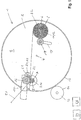
- a turning winding machine 1 has a winding core carrier 2 with two circular disk-shaped side parts 3, one of which is shown.
- the two side parts 3 are arranged at a distance from one another parallel to one another and with their center on the same axis of rotation 4.
- the side parts 3 holding means 5, 6 for releasably holding and rotatable bearings of winding cores 7, 8.
- the holding devices 5, 6 are pins, e.g. with cylindrical shape.
- the hubs 7, 8 are sleeves, in the ends of the pins 5, 6 can be used.
- the sleeves and the pins have tongue and groove connection 9, 10, 11, 12.
- the holding devices 5, 6 are each coupled to a winding drive device in order to set the winding cores 7, 8 about winding axes in rotation, which are parallel to the axis of rotation 4.
- arranged holding devices 5 On the left side of the axis of rotation 4 arranged holding devices 5 are located in a Anwickelposition and on the right side of the axis of rotation 4 arranged holding devices 6 are in a winding position.
- the winding core carrier 2 is coupled to a drive device 13 in order to rotate the winding core carrier 2 about its axis of rotation 4 selectively with the one holding devices 5 in the Anwickelposition at the same time with the other holding devices 6 in the winding position and vice versa.
- the drive device 13 and the winding core carrier 2 at their circumferences sprockets 14, 15, which engage in one another.
- a pressure roller 16 is arranged parallel to the winding core 7.
- the pressure roller 16 is mounted on a beam-shaped support structure 17. In the winding position shown, there is a gap between the winding core 7 arranged in the winding position and the pressure roller 16.
- the support structure 17 can be moved by means of a feed device from the position shown at a distance from the winding core 7 to the winding core 7, so that it rests against this and rolls on it.
- the feed device is designed such that the support structure 17 with the pressure roller 16 can be pulled out of the area between the side parts 3 in order to enable the winding core carrier 2 to rotate.
- a further pressure roller 18 is arranged between the two side parts 3.
- the further pressure roller 18 can be delivered by means of a device 10 for delivering radially to this winding core 8 down.
- this device for delivery 19 may be in particular a device which presses the further pressure roller 18 under bias against the circumference of the winding core 8.
- a web material 20 is guided on the side of the winding core 7 in the Anwickelposition over the circumference of the pressure roller 16 on the winding core 8 in the winding position.
- the web material 20 When winding on the winding core 8 in the winding position, the web material 20 can be pressed by the further pressure roller 18 against the winding core 8.
- the effective range of the charging electrode 21 is characterized by elliptic field lines 22.
- the charging electrode is aligned with its area of effect so that it touches the pressure roller 16 and radially meets the winding core 7 in the Anwickelposition.
- the charging electrode is electrically connected to a high voltage electric power source 23.
- a blowing device is integrated. This comprises a directed in the longitudinal direction of the needle electrode compressed air channel, a connecting piece for compressed air at one end of the needle electrode and a number of air outlet openings on the side of the needle electrode on which it has the needles from which the field lines go out.
- a cutting blade 24 of a cutting device 25 is arranged further away from the Anwickelstation in the direction of passage of the web material 20 than the Device for transferring electrical charges 21. Charging electrode and cutting blade 24 are located on the same side of the web material 20.
- the cutting device 25 comprises a displacement device which is designed to displace the cutting blade 24 perpendicular to the web material 20 in the region between the winding position and the winding position to cut through the web material 20.
- the electric high-voltage power supply 23, the winding core carrier drive device 13, the winding drive devices, the feed roller for the pressure roller 16, and the charging electrode 21 and the displacement device of the cutter 25 are connected to an electric control device 26.
- the controller 26 controls the cutter 25 so that the cutting blade 24 severes the web material 20.
- the control device 26 controls the high-voltage supply 23 such that the charging electrode 21 no longer compensates for the charging of the web material 20. Instead, the applied high voltage generates an electric field, which is the beginning of the web behind the cut on the winding core 7 in the Anwickelposition fixed.
- the pressure roller 16 can be pressed from the outside against the winding core 7.
- the control device 26 connects the blowing device with a high-pressure source via a switchable valve, so that the web start is additionally pressed against the winding core 7 by the compressed air emerging from the air outlet openings. As a result, the web start is wound on the winding core 7.
- the supporting structure 17 is displaced out of the area between the side parts 3 by means of the feed device. Furthermore, the cutting blade 24 is displaced out of the region between the two side parts 3 by means of the displacement device.
- the web material 20 is further guided over the pressure roller 16 on the winding core 7 and wound up. In this case, the web material 20 continues to pass the charging electrode 21. As a result, charging of the web material 20 can be further compensated by the charging electrode 21.
- the winding core carrier 2 After the replacement of the roller 27 by an empty winding core 8, the winding core carrier 2 is rotated by means of the drive device 13, so that the unwound winding core 2 enters the winding position and the partially wound winding core 7 reaches the winding position. In this case, further web material 20 is continuously wound onto the winding core 7.
- the pressure roller 16 and the charging electrode 21 are displaced by means of the feed device, and the cutting blade 24 is again displaced into the area between the side parts 3 by means of the displacement device. Then they take the in FIG. 1 and 2 shown position adjacent to the Anwickelposition, which is occupied by the unwound winding core 8.
Landscapes
- Replacement Of Web Rolls (AREA)
- Winding Of Webs (AREA)
- Manufacture Of Motors, Generators (AREA)
- Registering, Tensioning, Guiding Webs, And Rollers Therefor (AREA)
Abstract
Wendewickelmaschine mit elektrostatischer Fixierung umfassend:• einen Wickelkernträger mit Seitenteilen, die an verschiedenen Umfangspositionen Halteeinrichtungen zum drehbaren Lagern eines Wickelkernes aufweisen,• eine mit dem Wickelkernträger gekoppelte Antriebseinrichtung, um einen Wickelkern in eine Anwickelposition und gleichzeitig einen anderen Wickelkern in eine Aufwickelposition zu verlagern,• Anpresswalzen, von denen eine auf den Wickelkern in Anwickelposition und die andere auf den Wickelkern in Aufwickelposition zu verlagerbar ist,• eine Schneideinrichtung, um mit einem Schneidmesser ein über die Anpresswalze auf der dem Wickelkern in der Anwickelposition zugewandten Seite zum Wickelkern geführtes Bahnmaterial zu durchtrennen,• eine elektrische Hochspannungsquelle• eine damit verbundene Einrichtung zum Übertragen elektrischer Ladungen auf das Bahnmaterial zwischen der Anpresswalze und dem Verlagerungsweg des Schneidmessers,• eine elektrische Steuerungseinrichtung, die ausgebildet ist, um an die Einrichtung zum Übertragen beim Aufwickeln eine elektrische Spannung zur Kompensation auf dem Bahnmaterial vorhandener Ladungen anzulegen und beim Durchtrennen dem Bahnanfang eine Ladung zum Fixieren des Bahnanfanges auf dem Wickelkern zuzuführen.Reversible winding machine with electrostatic fixation comprising: • a winding core carrier with side parts which have holding devices for rotatably supporting a winding core at different circumferential positions, • a drive device coupled to the winding core carrier in order to shift one winding core into a winding position and at the same time another winding core into a winding position, • Pressure rollers, one of which can be moved to the winding core in the winding position and the other to the winding core in winding position, • a cutting device, with a cutting knife to cut through the pressure roller on the side facing the winding core in the winding position to the winding material, • an electrical high-voltage source • an associated device for transferring electrical charges to the web material between the pressure roller and the displacement path of the cutting knife, • an electrical control device Seal that is designed to apply an electrical voltage to the device for transferring during winding to compensate for charges present on the web material and to feed a charge to fix the beginning of the web on the winding core when severing the web.
Description
Die Erfindung betrifft eine Wendewickelmaschine zum Aufwickeln eines im Wesentlichen isolierenden Bahnmaterials mit elektrostatischer Fixierung des Bahnanfanges auf einem Wickelkern.The invention relates to a turning winding machine for winding a substantially insulating web material with electrostatic fixing of the web beginning on a winding core.
Bahnmaterialien werden insbesondere direkt nach ihrer Herstellung, ihrer Zerlegung in schmalere Bahnen, ihrer Bedruckung oder ihrer Weiterverarbeitung zu Beuteln, Säcken oder zu anderen Verpackungsmaterialien zu einer Rolle aufgewickelt. Hierfür werden insbesondere Wendelwickelmaschinen verwendet. Diese weisen einen drehbaren Wickelkernträger auf, auf dem mehrere Wickelkerne drehbar gelagert sind. Die Wickelkerne werden durch Drehen des Wickelkernträgers nacheinander in eine Anwickelposition zum Anwickeln eines Bahnanfanges und ineine Aufwickelposition zum weiteren Aufwickeln des Bahnmaterials verlagert. Wenn die Rolle in der Aufwickelposition vollgewickelt ist, wird mittels eines Schneidmessers das Bahnmaterial zwischen Anwickelposition und Aufwickelposition durchtrennt und der nachfolgende Bahnanfang auf dem Wickelkern in der Anwickelposition angewickelt. Beim Anwickeln wird die vollgewickelte Rolle vom Wickelkernträger abgenommen und durch einen unbewickelten Wickelkern ersetzt. Danach wird bei fortlaufendem Aufwickeln des Bahnmaterials auf den anderen Wickelkern der Wickelkernträger gedreht, bis der gerade bewickelte Wickelkern in die Aufwickelposition und der noch unbewickelte Wickelkern in die Anwickelposition gelangt ist und der Prozess beginnt von vorn.In particular, web materials are wound into rolls directly after their production, their separation into narrower webs, their printing or their further processing into bags, sacks or other packaging materials. For this purpose, in particular spiral winding machines are used. These have a rotatable winding core carrier on which a plurality of winding cores are rotatably mounted. The winding cores are displaced by rotating the winding core carrier successively in a Anwickelposition for wrapping a web start and in a winding position for further winding of the web material. When the roll is fully wound in the winding position, the web material between the winding position and winding position is severed by means of a cutting knife and the subsequent web start wound on the winding core in the Anwickelposition. When Anwickeln the fully wound roll is removed from the hub carrier and replaced by a unwound hub. Thereafter, with continuous winding of the web material on the other winding core, the winding core carrier is rotated until the wound winding core has reached the winding position and the still unwound winding core is in the winding position, and the process begins again.
Herkömmlicherweise werden als Wickelkerne Hülsen (z.B. aus Metall oder Pappe) mit speziellen Klebebändern verwendet, die den Bahnanfang am Umfang der Hülsen fixieren. Das Ankleben des Bahnanfanges begrenzt die Prozessgeschwindigkeit, ist wegen der Klebebänder teuer und bei Bahnmaterialien für Lebensmittel problematisch.Conventionally be used as hubs cores (eg made of metal or cardboard) with special adhesive tapes that fix the web start on the circumference of the sleeves. Sticking the web edge limits process speed, is expensive because of the tapes, and is problematic for food web materials.
Unter dem Begriff "kleberfreies Anwickeln" wird das Fixieren des Bahnanfangs auf einem Wickelkern beim Anwickeln mittels elektrostatischer Ladung bezeichnet.The term "adhesive-free Anwickeln" is the fixing of the web start on a winding core when winding by means of electrostatic charge referred to.
Bei der Verarbeitung eines im Wesentlichen isolierenden Bahnmaterials kann es insbesondere durch Fortbewegung, Umlenkung, Reibung, Dehnung sowie Einsatz elektrostatischer Druckhilfen (ESA) zu hohen elektrostatischen Aufladungen des Bahnmaterials kommen. Die Ladungen werden in dem zu einer Rolle aufgewickelten Material ähnlich gespeichert, wie in einem Wickelkondensator. Infolgedessen kann es beim Weiterverarbeiten des Bahnmaterials zu Spannungsüberschlägen kommen, die Arbeitspersonal gefährden. Deshalb sind Einrichtungen zum Entladen des durchlaufenden Bahnmaterials bekannt.In the processing of a substantially insulating web material, in particular by locomotion, deflection, friction, stretching and use of electrostatic pressure assistants (ESA), high electrostatic charges of the web material may occur. The charges are stored in the material wound into a roll similarly as in a wound capacitor. As a result, during processing of the web material, flashovers can occur which endanger workers. Therefore, means for unloading the continuous web material are known.
Die
Davon ausgehend liegt Erfindung die Aufgabe zugrunde, eine Wendewickelmaschine zum Aufwickeln eines im Wesentlichen isolierenden Bahnmaterials mit elektrostatischer Fixierung des Bahnanfanges mit günstigeren Herstellungs- und Betriebseigenschaften zu schaffen.Based on this, the invention has for its object to provide a turning winding machine for winding a substantially insulating web material with electrostatic fixation of the web beginning with cheaper manufacturing and operating characteristics.
Die Aufgabe wird durch eine Wendewickelmaschine mit den Merkmalen von Anspruch 1 gelöst. Vorteilhafte Ausführungsarten der Wendewickelmaschine sind in Unteransprüchen angegeben.The object is achieved by a turning winding machine with the features of claim 1. Advantageous embodiments of the turning winding machine are specified in subclaims.
Die erfindungsgemäße Wendewickelmaschine zum Aufwickeln eines im Wesentlichen isolierenden Bahnmaterials mit elektrostatischer Fixierung des Bahnanfanges auf einem Wickelkern umfasst:
- einen drehbar um eine Drehachse gelagerten Wickelkernträger mit zwei Seitenteilen, die in einem Abstand voneinander angeordnet sind und an den einander zugewandten Seiten in verschiedenen Umfangspositionen jeweils Halteeinrichtungen zum lösbaren Halten an den beiden Enden und drehbaren Lagern eines Wickelkernes um eine zur Drehachse parallele Wickelachse aufweisen,
- eine Antriebseinrichtung, die mit dem Wickelkernträger gekoppelt ist, um den Wickelkernträger mit den einen Halteinrichtungen und dem davon gehaltenen Wickelkern in eine Anwickelposition und gleichzeitig die anderen Halteeinrichtungen mit dem davon gehaltenen Wickelkern in eine Aufwickelposition zu verlagern,
- drehbar gelagerte Anpresswalzen, von denen eine zwischen den beiden Seitenteilen in radialer Richtung auf den Wickelkern in der Anwickelposition zu verlagerbar ist und die andere zwischen den beiden Seitenteilen in radialer Richtung auf den Wickelkern in der Aufwickelposition zu verlagerbar ist,
- eine Schneideinrichtung mit einem Schneidmesser und einer Verlagerungseinrichtung, um das Schneidmesser zwischen den beiden Seitenteilen in den Abstandsbereich zwischen der Anwickelposition und der Aufwickelposition hinein zu verlagern, um hierbei ein über die Anpresswalze neben der Anwickelposition auf der den Wickelkern in der Anwickelposition zugewandten Seite zum Wickelkern in der Aufwickelposition geführtes Bahnmaterial zu durchtrennen,
- eine Einrichtung zum Übertragen elektrischer Ladungen auf das Bahnmaterial, die zwischen der Anpresswalze, die auf den Wickelkern in der Anwickelposition zu verlagerbar ist, und dem Verlagerungsweg des Schneidmessers beim Auftrennen des Bahnmaterials angeordnet ist,
- mindestens eine elektrische Hochspannungsquelle, die mit der Einrichtung zum Übertragen elektrischer Ladung verbunden ist und
- eine elektrische Steuerungseinrichtung, die ausgebildet ist, beim Aufwickeln des Bahnmaterials auf den Wickelkern an die Einrichtung zum Übertragen elektrischer Ladungen mindestens eine elektrische Spannung mit einer Höhe und/oder Polarität anzulegen, die zur Kompensation auf dem Bahnmaterial vorhandener Ladungen geeignet ist, und beim Durchtrennen des Bahnmaterials an die Einrichtung zum Übertragen elektrischer Ladungen mindestens eine elektrische Spannung mit einer Höhe und/oder Polarität anzulegen, die geeignet ist, dem auf das abgetrennte Bahnende nachfolgenden Bahnanfang eine Ladung zum Fixieren des Bahnanfanges auf dem Wickelkern in der Anwickelposition zuzuführen.
- a winding core carrier rotatably mounted about an axis of rotation and having two side parts which are arranged at a distance from one another and have holding devices for releasably holding at the two ends and rotatable bearings of a winding core about a winding axis parallel to the axis of rotation on the facing sides in different circumferential positions,
- drive means coupled to the winding core carrier to shift the winding core carrier with the one holding means and the winding core held thereon to a winding position and at the same time the other holding means with the winding core held thereby to a winding position;
- rotatably mounted pressure rollers, one of which is displaceable between the two side parts in the radial direction on the winding core in the Anwickelposition and the other between the two side parts in the radial direction to the winding core in the winding position to be displaced,
- a cutting device with a cutting blade and a displacement device to shift the cutting blade between the two side parts in the distance range between the Anwickelposition and the winding position in order to do this via the pressure roller next to the Anwickelposition on the winding core in the Anwickelposition facing side to cut to the winding core in the winding position guided web material,
- a device for transferring electrical charges to the web material, which is arranged between the pressure roller, which is displaceable on the winding core in the Anwickelposition, and the displacement path of the cutting blade in the separation of the web material,
- at least one high voltage electrical source connected to the electrical charge transfer device, and
- an electrical control device, which is designed to apply at least one electrical voltage with a height and / or polarity, which is suitable for compensating for charges present on the web material, during winding of the web material onto the winding core, to the device for transferring electrical charges Web material to the means for transmitting electrical charges to apply at least one electrical voltage with a height and / or polarity, which is adapted to supply the beginning of the severed tail end of the web a charge for fixing the web start on the winding core in the Anwickelposition.
Bei der erfindungsgemäßen Wendewickelmaschine wird mit derselben Einrichtung zum Übertragen elektrischer Ladungen auf den Bahnanfang Ladung zum Fixieren auf dem Wickelkern in der Anwickelposition aufgebracht und beim weiteren Aufwickeln auf denselben Wickelkern die zur Kompensation einer Aufladung bei der Herstellung oder Verarbeitung des Bahnmaterials erforderliche Ladung auf das Bahnmaterial aufgebracht. Dies wird durch Anordnung der Einrichtung zum Übertragen elektrischer Ladungen zwischen der Anpresswalze, die auf den Wickelkern in der Anwickelposition zu verlagerbar ist, und dem Verlagerungsweg des Schneidmessers beim Auftrennen des Bahnmaterials erreicht. Aufgrund dieser Anordnung kann nämlich sowohl unerwünschte Ladung des Bahnmaterials vor dem Aufwickeln auf den Wickelkern in der Aufwickelposition kompensiert als auch nach dem Durchtrennen des Bahnmaterials der nachfolgende Bahnanfang mit einer geeigneten Ladung für das Fixieren auf dem Wickelkern in der Anwickelposition versehen werden. Mittels der elektrischen Steuerungseinrichtung kann die Aufladung des Bahnanfanges vor dem Fixieren so gesteuert werden, dass trotz einer Aufladung des Bahnmaterials bei seiner Herstellung oder Weiterverarbeitung eine hinreichende Fixierung auf dem Wickelkern erzielt wird. Dadurch, dass die Einrichtung zum Übertragen elektrischer Ladungen sowohl das Fixieren des Bahnanfangs als auch die Kompensation elektrischer Aufladungen des Bahnmaterials übernimmt, werden Bauteile eingespart und der Platzbedarf vermindert. Hierdurch kann der Aufwand für die Herstellung und Betrieb herabgesetzt werden.In the turn winding machine according to the invention is applied with the same means for transferring electrical charges on the web start charge for fixing on the winding core in the Anwickelposition and applied to the same winding core to charge the charge in the production or processing of the web material required charge on the web material on further winding , This is done by arranging the means for transmitting electrical charges between the pressure roller, which is to be displaced on the winding core in the Anwickelposition, and reaches the displacement path of the cutting blade in the separation of the web material. Because of this arrangement, both unwanted loading of the web material before being wound onto the winding core in the winding position can be compensated for, and after the web material has been severed, the subsequent web start can be provided with a suitable charge for fixing on the winding core in the winding position. By means of the electrical control device, the charging of the web beginning can be controlled prior to fixing so that despite a charging of the web material in its production or further processing, a sufficient fixation on the winding core is achieved. The fact that the device for transmitting electrical charges both takes care of fixing the web start and the compensation of electrical charges of the web material, components are saved and reduced space requirements. As a result, the cost of production and operation can be reduced.
Gemäß einer Ausführungsart der Erfindung liefert die elektrische Hochspannungsquelle elektrische Hochspannungen unterschiedlicher Polarität. Die elektrische Steuerungseinrichtung steuert, welche der elektrischen Hochspannungen mit unterschiedlicher Polarität an die Einrichtung zum Übertragen elektrischer Ladungen angelegt werden. Bei Ausführung der Einrichtung zum Übertragen elektrischer Ladungen als Nadelelektrode kann zur Kompensation an verschiedene Nadelreihen eine Hochspannung unterschiedlicher Polarität oder an eine Nadelreihe einer Hochspannung bestimmter Polarität und an eine andere Nadelreihe Masse angelegt werden. Bei einer Nadelelektrode mit nur einer einzigen Nadelreihe kann an diese Nadelreihe eine Hochspannung bestimmter Polarität und das an Gehäuse Masse angelegt werden. Zum Aufladen des Bahnanfanges für die Fixierung am Wickelkern kann an eine oder zwei Nadelreihen einer Nadelelektrode eine Hochspannung derselben Polarität angelegt werden.According to one embodiment of the invention, the electrical high voltage source supplies high voltages of different polarity. The electrical controller controls which of the high voltage electrical voltages of different polarity are applied to the electrical charge transfer device. In the embodiment of the device for transmitting electrical charges as a needle electrode can be applied to compensate for different rows of needles a high voltage of different polarity or to a row of needles of a high voltage of certain polarity and to another row of pins mass. In the case of a needle electrode with only a single row of needles, it is possible to apply to this row of needles a high voltage of a certain polarity and that to the housing ground. To load the web beginning for the fixation on the winding core A high voltage of the same polarity can be applied to one or two rows of needles of a needle electrode.
Gemäß einer weiteren Ausführungsart liefert die elektrische Hochspannungsquelle mindestens eine einstellbare Hochspannung an die Einrichtung zum Übertragen elektrischer Ladungen auf das Bahnmaterial. Durch Einstellen der Hochspannung ist es möglich, die dem Bahnmaterial zugeführte Ladung zur Kompensation einer Aufladung des Bahnmaterials zu optimieren. Ferner kann die dem Bahnanfang zum Fixieren des Bahnmaterials auf den Wickelkern zugeführte Ladung optimiert werden.In another embodiment, the high voltage electrical power source provides at least one adjustable high voltage to the means for transferring electrical charges to the web material. By adjusting the high voltage, it is possible to optimize the charge applied to the web material to compensate for charging of the web material. Furthermore, the charge supplied to the web start for fixing the web material to the winding core can be optimized.
Gemäß einer weiteren Ausführungsart ist die elektrische Steuerungseinrichtung so ausgebildet, dass sie an die Einrichtung zum Übertragen elektrischer Ladungen mindestens eine elektrische Spannung mit einer Höhe und/oder Polarität anlegt, die eine Aufladung des Bahnanfanges bewirkt, welche von der Aufladung des zugeführten Bahnmaterials abhängt. Hierbei kann die Höhe und/oder Polarität der Ladung zum Fixieren des Bahnanfangs auf dem Wickelkern in Abhängigkeit von der Höhe und/oder Polarität der Ladung zur Kompensation der Aufladung des Bahnmaterials eingestellt werden, z.B. gemäß einer Tabelle, die auf Erfahrungswerten basiert.According to a further embodiment, the electrical control device is designed such that it applies to the means for transmitting electrical charges at least one electrical voltage with a height and / or polarity which causes a charging of the web beginning, which depends on the charging of the supplied web material. Here, the height and / or polarity of the charge for fixing the web start on the winding core can be adjusted depending on the height and / or polarity of the charge to compensate for the charging of the web material, e.g. according to a table based on empirical values.
Gemäß einer weiteren Ausführungsart ist mindestens eine Feldstärkemessvorrichtung so angeordnet, dass sie das der Wendewickelmaschine zugeführte Bahnmaterial, vorzugsweise beim Umlenken auf den Wickelkern oder auf den Wickelkern erfasst, wobei die Feldstärkemessvorrichtung die Aufladung ermittelt, die das Bahnmaterial aufweist, und mit der elektrischen Steuerungseinrichtung verbunden ist, die ausgebildet ist, eine Hochspannung mit einer Höhe und/oder Polarität an die Einrichtung zum Übertragen elektrischer Ladungen anzulegen, die von der von der Feldstärkemessvorrichtung gemessenen Aufladung des Bahnmaterials abhängt. Dabei kann die elektrische Steuerungseinrichtung unter Berücksichtigung der gemessenen Aufladung die zur Kompensation der Aufladung erforderliche Hochspannung und/oder die zum Aufladen des Bahnanfangs für das Fixieren auf dem Wickelkern erforderliche Hochspannung ermitteln.According to a further embodiment, at least one field strength measuring device is arranged such that it detects the web material supplied to the turning winding machine, preferably when deflecting onto the winding core or onto the winding core, wherein the field strength measuring device determines the charge having the web material and is connected to the electrical control device adapted to apply a high voltage having a magnitude and / or polarity to the means for transmitting electrical charges, which is dependent on the charging of the sheet material measured by the field strength measuring device depends. In this case, the electrical control device, taking into account the measured charge, determine the high voltage required to compensate for the charging and / or the high voltage required for charging the web start for fixing on the winding core.
Gemäß einer weiteren Ausführungsart ist die elektrische Steuerungseinrichtung so ausgebildet, dass sie beim Aufwickeln des Bahnmaterials auf den Wickelkern an die Einrichtung zum Übertragen elektrischer Ladungen eine Hochspannung mit einer Höhe und/oder Polarität anlegt, die eine minimale Aufladung des auf den Wickelkern aufgewickelten Bahnmaterials bewirkt. Hierdurch wird das Risiko von Spannungsüberschlägen minimiert.According to a further embodiment, the electrical control device is designed such that when winding the web material onto the winding core, it applies to the electrical charge transfer device a high voltage having a height and / or polarity which causes minimal charging of the web material wound on the winding core. This minimizes the risk of flashovers.
Gemäß einer bevorzugten Ausführungsart der Erfindung ist die Einrichtung zum Übertragen elektrischer Ladungen auf das Bahnmaterial eine Aufladeelektrode, die so angeordnet ist, dass das Bahnmaterial den Wirkungsbereich der Aufladeelektrode durchläuft. Da die Aufladeelektrode aus einem Abstand auf das Bahnmaterial einwirken kann, ist eine Anordnung und/oder Verlagerung der Aufladeelektrode möglich, sodass sie nicht mit bewegten Teilen kollidiert. Zudem können durch die Anordnung der Aufladeelektrode in einem Abstand vom Bahnmaterial Änderungen des Verlaufs des Bahnmaterials in begrenztem Umfang überbrückt werden, beispielsweise aufgrund des Anwachsens des Rollendurchmessers beim Aufwickeln des Bahnmaterials auf den Wickelkern.According to a preferred embodiment of the invention, the means for transferring electrical charges to the web material is a charging electrode arranged so that the web material passes through the area of action of the charging electrode. Since the charging electrode can act on the web material from a distance, placement and / or displacement of the charging electrode is possible, so that it does not collide with moving parts. In addition, the arrangement of the charging electrode at a distance from the web material changes of the course of the web material can be bridged to a limited extent, for example due to the increase in the roll diameter during winding of the web material on the winding core.
Gemäß einer weiteren Ausführungsart ist der Wirkbereich der Aufladeelektrode definiert als der Bereich, in dem die Feldstärke des von der Aufladeelektrode erzeugten elektrischen Feldes mindestens 1 % der maximalen Feldstärke dieses Feldes beträgt, vorzugsweise mindestens 5 %, vorzugsweise mindestens 10 %, weiterhin vorzugsweise mindestens 20 %, vorzugsweise mindestens 50 %.According to a further embodiment, the effective range of the charging electrode is defined as the range in which the field strength of the electric field generated by the charging electrode is at least 1% of the maximum field strength of this field, preferably at least 5%, preferably at least 10%, furthermore preferably at least 20%. , preferably at least 50%.
Gemäß einer weiteren Ausführungsart ist die Aufladeelektrode beim Fixieren des Bahnanfanges auf dem Wickelkern so angeordnet, dass ihr Wirkbereich den äußeren Umfang des in der Anwickelstation angeordneten Wickelkernes erfasst. Dies ist besonders vorteilhaft für das Fixieren des Bahnanfangs auf dem Wickelkern.According to a further embodiment, the charging electrode is arranged on the winding core during fixing of the web beginning so that its effective area covers the outer circumference of the winding core arranged in the winding station. This is particularly advantageous for fixing the web start on the winding core.
Gemäß einer weiteren Ausführungsart ist die Aufladeelektrode neben der auf den Wickelkern in der Anwickelstation zu verlagerbaren Anpresswalze auf derselben Seite des Bahnmaterials wie diese Anpresswalze angeordnet. Gemäß einer weiteren Ausführungsart ist die Aufladeelektrode beim Fixieren des Bahnanfangs auf dem Wickelkern mit ihrem Wirkbereich durch das Bahnmaterial hindurch auf den Außenumfang des Wickelkerns in der Anwickelstation gerichtet.According to a further embodiment, the charging electrode is arranged next to the pressure roller to be displaced on the winding core in the Anwickelstation on the same side of the web material as this pressure roller. According to a further embodiment, the charging electrode is directed on the outer circumference of the winding core in the Anwickelstation when fixing the web start on the winding core with its effective range through the web material.
Gemäß einer weiteren Ausführungsart ist die Aufladeelektrode mit ihrem Wirkbereich tangential zu auf dem Wickelkern in der Anwickelstation zu verlagerbaren Anpresswalze ausgerichtet. Gemäß einer weiteren Ausführungsart ist die Aufladeelektrode beim Durchtrennen des Bahnmaterials radial zum Wickelkern in der Anwickelstationen ausgerichtet.According to a further embodiment, the charging electrode is aligned with its effective range tangentially to be applied to the winding core in the Anwickelstation to be displaced pressure roller. According to a further embodiment, the charging electrode is aligned radially to the winding core in the Anwickelstationen when cutting the web material.
Gemäß einer weiteren Ausführungsart ist die Aufladeelektrode eine balkenförmige Aufladeelektrode. Gemäß einer weiteren Ausführungsart ist die Aufladeelektrode eine Nadelelektrode. Die Aufladeelektrode ist vorzugsweise so ausgebildet, wie eine Aufladeelektrode, die für das "top-loading" von Presseuren bei elektrostatischen Druckhilfen (ESA) eingesetzt werden. Gemäß einer bevorzugten Ausführungsart ist die Aufladeelektrode eine balkenförmige Nadelelektrode, die ausgebildet ist, wie in der
Bei einer Nadelelektrode ist der Wirkungsbereich axial in Richtung der Nadeln ausgerichtet. Der Wirkungsbereich ist charakterisierbar durch den Verlauf der Feldlinien. Hierbei handelt es sich um Linien konstanter Feldstärke. Bei einer Nadelelektrode ist der Verlauf der Feldlinien elliptisch, wobei die Hauptachsen der Ellipsen in Richtung der Nadeln und die Nebenachsen senkrecht dazu ausgerichtet sind.In the case of a needle electrode, the area of action is aligned axially in the direction of the needles. The sphere of action is characterized by the course of the field lines. These are lines of constant field strength. In a needle electrode, the course of the field lines is elliptical, with the major axes of the ellipses in the direction of the needles and the minor axes aligned perpendicular thereto.
Gemäß einer weiteren Ausführungsart ist die Schneideinrichtung so ausgebildet, dass der Verlagerungsweg des Schneidmessers beim Auftrennen des Bahnmaterials zwischen dem Wickelkern in der Anwickelposition und der Drehachse des Wickelkernträgers verläuft. Vorzugsweise verläuft der Verlagerungsweg des Schneidmessers in einem Abstand von dem Wickelkern in der Anwickelposition, der geringer ist, als die Hälfte des Abstandes dieses Wickelkerns von der Drehachse des Wickelkernträgers. Hierdurch wird das Bahnmaterial in kurzem Abstand vom Wickelkern in der Anwickelposition aufgetrennt, sodass der nachfolgende Bahnanfang sich um den Wickelkern in der Anwickelposition herumlegt. Das Herumlegen und Fixieren wird durch die elektrische Aufladung des Bahnanfangs und gegebenenfalls des Wickelkerns erreicht.According to a further embodiment, the cutting device is designed such that the displacement path of the cutting blade when separating the web material between the winding core in the Anwickelposition and the axis of rotation of the winding core carrier extends. Preferably, the displacement path of the cutting blade extends at a distance from the winding core in the Anwickelposition, which is less than half the distance of this winding core from the axis of rotation of the winding core carrier. As a result, the web material is separated at a short distance from the winding core in the Anwickelposition, so that the subsequent web start is wrapped around the winding core in the Anwickelposition. The laying around and fixing is achieved by the electrical charge of the web start and possibly the winding core.
Gemäß einer weiteren Ausführungsart sind die Einrichtung zum Übertragen elektrischer Ladungen und die neben der Anwickelposition angeordnete Anpresswalze an derselben Tragstruktur befestigt. Dies ist vorteilhaft für eine Positionierung der Einrichtung zum Übertragen elektrischer Ladungen, sodass der Bahnanfang sicher auf dem Wickelkern in der Anwickelposition fixiert wird.According to a further embodiment, the device for transferring electrical charges and the pressure roller arranged next to the winding position are fastened to the same support structure. This is advantageous for a positioning of the device for transmitting electrical charges, so that the web start is securely fixed on the winding core in the Anwickelposition.
Gemäß einer weiteren Ausführungsart ist die Tragstruktur mittels einer Zustelleinrichtung in den Bereich zwischen die Seitenteile hinein und aus diesem Bereich heraus verlagerbar. Durch Verlagerung der Tragstruktur aus dem Bereich zwischen den beiden Seitenteilen heraus wird das Drehen des Wickelkernträgers ohne Kollision mit der Tragstruktur und der daran befestigten Bauteile ermöglicht. Gemäß einer weiteren Ausführungsart ist die elektrische Steuerungseinrichtung mit der Zustelleinrichtung verbunden und so ausgebildet, dass die Tragstruktur mit der daran gelagerten Anpresswalze nach dem Anwickeln des Bahnanfanges aus dem Bereich zwischen den beiden Seitenteilen herausverlagert wird und nach dem Drehen des Wickelkerns, auf dem das Bahnmaterial aufgewickelt wird, aus der Anwickelposition in die Aufwickelposition, in die Position neben dem in die Anwickelposition gedrehten, unbewickelten Wickelkern verlagert wird. Wenn die Tragstruktur aus dem Bereich zwischen den beiden Seitenteilen herausverlagert ist, läuft das Bahnmaterial weiterhin über die daran gelagerte Anpresswalze auf den Wickelkern in der Anwickelposition. Hierbei wird das Bahnmaterial weiterhin an der Einrichtung zum Übertragen elektrischer Ladungen vorbeigeführt, die an der Tragstruktur befestigt ist. Hierdurch werden Aufladungen des Bahnmaterials auch dann kompensiert, wenn die Tragstruktur aus dem Bereich zwischen den Seitenteilen herausverlagert ist. Auch wenn der Wickelkernträger den Wickelkern aus der Anwickelposition in die Aufwickelposition dreht, wird das Bahnmaterial an der Einrichtung zum Übertragen elektrischer Ladungen vorbeigeführt, sodass die Kompensation von Aufladungen fortgeführt werden kann. Nachdem der Wickelkernträger den Wickelkern aus der Anwickelposition in die Aufwickelposition gedreht hat, wird die Tragstruktur mit der Anpresswalze zwischen die Seitenteile neben den noch unbewickelten Wickelkern in der Anwickelposition verlagert. Hierbei verbleibt die Einrichtung zum Übertragen elektrischer Ladungen in der Nähe des durchlaufenden Bahnmaterials, sodass es Aufladungen desselben weiterhin kompensieren kann. Beim nachfolgenden Trennen des Bahnmaterials wird an die Einrichtung zum Übertragen elektrischer Ladungen eine Hochspannung zum Fixieren des Bahnanfanges an dem Wickelkern in der Anwickelposition übertragen.According to a further embodiment, the support structure is displaceable by means of a feed device into the region between the side parts and out of this region. By shifting the support structure out of the area between the two side parts, rotation of the winding core carrier is made possible without colliding with the support structure and the components attached thereto. According to a further embodiment, the electrical control device is connected to the feed device and designed so that the support structure with the pressure roller mounted thereon is displaced out of the area between the two side parts after the start of the web and after the winding core has been wound on which the web material is wound is shifted, from the Anwickelposition to the winding position, in the position next to the wound in the Anwickelposition, unwound winding core. If the support structure is displaced out of the region between the two side parts, the web material continues to run on the winding roller mounted thereon on the winding core in the Anwickelposition. At this time, the sheet material is further guided past the electrical charge transfer device fixed to the support structure. As a result, charges of the web material are compensated even if the support structure is displaced out of the area between the side parts. Even if the reel hub rotates the reel from the coiling position to the reeling position, the web is passed by the device for transferring electrical charges, so that the charging compensation can be continued. After the winding core carrier the winding core has rotated from the Anwickelposition in the winding position, the support structure is displaced with the pressure roller between the side parts next to the still unwound winding core in the Anwickelposition. Here, the means for transferring electrical charges remains in the vicinity of the continuous web material, so that it can continue to compensate for charges thereof. During the subsequent separation of the web material, a high voltage for fixing the web start to the winding core in the winding position is transmitted to the device for transferring electrical charges.
Gemäß einer weiteren Ausführungsart umfasst die Wendewickelmaschine eine Anblaseinrichtung, welche mindestens eine Luftaustrittsöffnung aufweist, die auf das Bahnmaterial zwischen der Anpresswalze, die auf den Wickelkern in der Anwickelposition zu verlagerbar ist und dem Verlagerungsweg des Schneidmessers beim Auftrennen des Bahnmaterials gerichtet ist und die an eine Druckluftquelle anschließbar oder angeschlossen ist. Die Anblaseinrichtung unterstützt das Anlegen und Fixieren des Bahnanfanges an dem in der Anwickelposition angeordneten Wickelkern. Gemäß einer weiteren Ausführungsart ist die Anblaseinrichtung balkenförmig mit einem Druckluftkanal, der an eine Druckluftquelle anschließbar oder angeschlossen ist, und mindestens eine Luftaustrittsöffnung, vorzugsweise mindestens eine Reihe Luftaustrittsöffnungen, auf einer Seite aufweist, wobei jede Luftaustrittsöffnung mit dem Druckluftkanal verbunden ist. Die balkenförmige Anblaseinrichtung ist mit dem mindestens einen Luftaustrittsloch auf das Bahnmaterial und vorzugsweise senkrecht zur Laufrichtung des Bahnmaterials ausgerichtet.According to a further embodiment, the turning winding machine comprises a blowing device, which has at least one air outlet opening, which is directed to the web material between the pressure roller, which is to be displaced on the winding core in the Anwickelposition and the displacement path of the cutting blade in the separation of the web material and to a compressed air source connectable or connected. The blowing device supports the application and fixing of the web beginning at the arranged in the Anwickelposition winding core. According to a further embodiment, the blowing device is bar-shaped with a compressed air channel which is connectable or connected to a compressed air source, and at least one air outlet opening, preferably at least one row of air outlet openings, on one side, each air outlet opening is connected to the compressed air channel. The beam-shaped blowing device is aligned with the at least one air outlet hole on the web material and preferably perpendicular to the running direction of the web material.
Gemäß einer weiteren Ausführungsart ist die Anblaseinrichtung in die Einrichtung zum Übertragen elektrischer Ladungen integriert oder daran angebaut. Gemäß einer weiteren Ausführungsart ist die Einrichtung zum Übertragen elektrischer Ladungen mit integrierter Anblaseinrichtung eine Nadelelektrode mit einer oder zwei Nadelreihen, die einen Druckluftkanal und eine Reihe Luftaustrittsöffnungen aufweist, die mit dem Druckluftkanal verbunden sind. Dies ist eine besonders platzsparende Ausführung. Gemäß einer weiteren Ausführungsart sind die Luftaustrittsöffnungen zwischen zwei Nadelreihen angeordnet. Gemäß einer weiteren Ausführungsart einer Nadelelektrode mit einer oder zwei Nadelreihen ist der Druckluftkanal mit einem Anschlussstutzen für Druckluft verbunden, der von einem Ende der Nadelelektrode vorsteht.According to a further embodiment, the blowing device is integrated into or attached to the device for transmitting electrical charges. According to a further embodiment, the device for transferring electrical charges with integrated blowing device is a needle electrode with one or two rows of needles, having a compressed air channel and a number of air outlet openings which are connected to the compressed air channel. This is a particularly space-saving design. According to a further embodiment, the air outlet openings are arranged between two rows of needles. According to a further embodiment of a needle electrode with one or two rows of needles, the compressed air channel is connected to a connecting piece for compressed air which protrudes from one end of the needle electrode.
Gemäß einer weiteren Ausführungsart ist die Einrichtung zum Übertragen elektrischer Ladungen eine balkenförmige Nadelelektrode mit einer oder zwei Nadelreihen und ist die Anblaseinrichtung eine seitlich an die balkenförmige Nadelelektrode angebaute balkenförmige Anblaseinrichtung, die wie oben beschrieben einen Druckluftkanal und mindestens eine damit verbundene Luftaustrittsöffnung aufweist.According to a further embodiment, the device for transmitting electrical charges is a bar-shaped needle electrode with one or two rows of needles, and the blowing device is a bar-shaped blowing device mounted laterally on the bar-shaped needle electrode and having a compressed-air channel and at least one air outlet opening connected thereto as described above.
Gemäß einer weiteren Ausführungsart ist die Anblaseinrichtung mit einem schaltbaren Ventil (Schaltventil) verbunden, das mit der Druckluftquelle verbunden oder verbindbar ist. Über das schaltbare Ventil kann die Anblaseinrichtung beim Auftrennen des Bahnmaterials mit der Druckluftquelle verbunden werden, um das Anwickeln zu unterstützen. Beim weiteren Aufwickeln kann die Anblaseinrichtung über das schaltbare Ventil von der Druckluftquelle getrennt werden. Gemäß einer weiteren Ausführungsart ist das schaltbare Ventil mit einem Druckluftkanal der Anblaseinrichtung verbunden, der wiederum mit der mindestens einen Luftaustrittsöffnung verbunden ist.According to a further embodiment, the blowing device is connected to a switchable valve (switching valve), which is connected or connectable to the compressed air source. Via the switchable valve, the blowing device can be connected to the compressed air source during the separation of the web material in order to assist the winding. Upon further winding, the blowing device can be separated from the compressed air source via the switchable valve. According to a further embodiment, the switchable valve is connected to a compressed air channel of the blowing device, which in turn is connected to the at least one air outlet opening.
Gemäß einer weiteren Ausführungsart ist die elektrische Steuerungseinrichtung mit dem schaltbaren Ventil verbunden und ausgebildet, beim Durchtrennen des Bahnmaterials das schaltbare Ventil zu öffnen, sodass Druckluft durch die mindestens eine Luftaustrittsöffnung der Anblaseinrichtung austritt, die den Bahnanfang zum Wickelkern in der Anwickelposition bewegt. Gemäß einer weiteren Ausführungsart legt die elektrische Steuerungseinrichtung gleichzeitig die elektrische Hochspannung zum Fixieren des Bahnanfanges an die Einrichtung zum Übertragen elektrischer Ladungen an und schaltet das schaltbare Ventil ein, welches die Anblaseinrichtung mit der Druckluftquelle verbindet. Gemäß einer weiteren Ausführungsart ist die elektrische Steuerungseinrichtung ausgebildet, das schaltbare Ventil nach dem Anwickeln des Bahnanfangs an den Wickelkern in der Anwickelposition zu schließen. Gemäß einer weiteren Ausführungsart schaltet die elektrische Steuerungseinrichtung die Hochspannung zum Fixieren des Bahnanfanges und die Anblaseinrichtung gleichzeitig aus. Es ist aber auch möglich, das Einschalten der Hochspannung zum Fixieren und das Einschalten der Anblaseinrichtung und/oder das Ausschalten der Hochspannung zum Fixieren sowie das Ausschalten der Anblaseinrichtung zeitversetzt durchzuführen.According to a further embodiment, the electrical control device is connected to the switchable valve and designed to open the switchable valve when severing the web material, so that compressed air through the at least an air outlet opening of the blowing device exits, which moves the web start to the winding core in the Anwickelposition. According to another embodiment, the electrical control device simultaneously applies the electrical high voltage for fixing the web start to the device for transferring electrical charges and switches on the switchable valve, which connects the blowing device to the compressed air source. According to a further embodiment, the electrical control device is designed to close the switchable valve after winding the web start to the winding core in the Anwickelposition. According to a further embodiment, the electrical control device switches off the high voltage for fixing the web start and the blowing device simultaneously. But it is also possible to perform the switching on of the high voltage for fixing and switching on the blowing device and / or switching off the high voltage for fixing and switching off the blowing device with a time delay.
Gemäß einer weiteren Ausführungsart ist die Schneideinrichtung so ausgebildet, dass das Schneidmesser in der Ausgangsposition, bevor es den Weg zum Auftrennen des Bahnmaterials durchläuft, auf derselben Seite des Bahnmaterials angeordnet ist, wie die Einrichtung zum Übertragen elektrischer Ladungen. Hierdurch ist es möglich, die Schneideinrichtung mit dem Schneidmesser von derselben Seite an das Bahnmaterial heranzuführen, wie die Einrichtung zum Übertragen elektrischer Ladungen. Dies ist vorteilhaft für eine platzsparende Konstruktion. Gemäß einer weiteren Ausführungsart umfasst die Schneideinrichtung eine Verlagerungseinrichtung, welche ausgebildet ist, das Schneidmesser in eine das Bahnmaterial schneidenden Richtung zu verlagern, um das Bahnmaterial durchzutrennen. Gemäß einer weiteren Ausführungsart ist die Verlagerungseinrichtung ausgebildet, das Schneidmesser aus dem Bereich zwischen den beiden Seitenteilen heraus und in den Bereich zwischen den beiden Seitenteilen hinein zu verlagern. Wenn das Schneidmesser aus dem Bereich zwischen den Seitenteilen heraus verlagert ist, behindert es nicht das Drehen des Wickelkernträgers. Zum Durchtrennen des Bahnmaterials wird das Schneidmesser in den Bereich zwischen den Seitenteilen hinein verlagert. Gemäß einer bevorzugten Ausführungsart ist die Verlagerungseinrichtung eine von der Zustelleinrichtung getrennte Einrichtung.According to a further embodiment, the cutting device is designed so that the cutting blade in the starting position, before it passes through the path for separating the web material, is arranged on the same side of the web material as the device for transferring electrical charges. This makes it possible to bring the cutting device with the cutting blade from the same side of the web material as the means for transmitting electrical charges. This is advantageous for a space-saving design. According to a further embodiment, the cutting device comprises a displacement device, which is designed to displace the cutting blade in a direction cutting the web material in order to sever the web material. According to a further embodiment, the displacement device is designed to displace the cutting blade out of the region between the two side parts and into the region between the two side parts. When the cutting knife is shifted out of the area between the side parts, it does not hinder the rotation of the hub carrier. To cut through the web material, the cutting blade is displaced into the region between the side parts. According to a preferred embodiment, the displacement device is a separate device from the delivery device.
Gemäß einer bevorzugten Ausführungsart hat das Schneidmesser eine Schneidkante, die sich über die gesamte Breite des Bahnmaterials erstreckt. Hierdurch wird das Bandmaterial geradlinig abgetrennt und gleichmäßig auf dem Wickelkern aufgewickelt.According to a preferred embodiment, the cutting blade has a cutting edge which extends over the entire width of the web material. As a result, the strip material is separated in a straight line and wound evenly on the winding core.
Gemäß einer weiteren Ausführungsart sind die Seitenteile des Wickelkernträgers Scheiben, insbesondere Kreisscheiben. Gemäß einer weiteren Ausführungsart weisen die Seitenteile jeweils radial bezüglich der Drehachse vorstehende Tragarme auf, an denen die Halteeinrichtungen angeordnet sind. Zwischen den Tragarmen sind vorzugsweise Freiräume vorhanden. Die Seitenteile können ausschließlich von den Tragarmen gebildet sein.According to a further embodiment, the side parts of the winding core carrier are disks, in particular circular disks. According to a further embodiment, the side parts each have radially with respect to the axis of rotation projecting support arms on which the holding devices are arranged. Free spaces are preferably present between the support arms. The side parts can be formed solely by the support arms.
Gemäß einer weiteren Ausführungsart ist die elektrische Steuerungseinrichtung so ausgebildet, dass sie während des Auftrennens des Bahnmaterials mittels der Schneideinrichtung und/oder eine definierte Zeitspanne vor dem Durchtrennen des Bahnmaterials mittels der Schneideinrichtung der Einrichtung zum Übertragen elektrischer Ladung keine elektrische Hochspannung zur Kompensation einer Aufladung des Bahnmaterials mehr zuführt und stattdessen der Einrichtung zum Übertragen elektrischer Ladung eine elektrische Hochspannung zum Fixieren des Bahnanfangs an dem Wickelkern in der Anwickelposition zuführt. Hierdurch wird sichergestellt, dass dem Bahnanfang Ladungen zum Fixieren auf dem Wickelkern in der Anwickelposition zugeführt werden. Wenn die Ladungen zum Fixieren dem Bahnmaterial bereits vor dem Durchtrennen durch das Schneidmesser zugeführt werden, wird auch dem vorauseilende Bahnende Ladungen zugeführt, deren Höhe jedoch so gering ist, dass sie keine das Arbeitspersonal gefährdenden Spannungsüberschläge von der Rolle verursacht. Zudem können diese Ladungen das Bahnende auf der fertiggewickelten Rolle fixieren. Die Zeitspanne, während der die entsprechenden Ladungen vor dem Auftrennen des Bahnmaterials zugeführt werden, kann in Abhängigkeit von der Durchlaufgeschwindigkeit, der für das Fixieren des Bahnanfangs am Wickelkern in der Anwickelposition erforderlichen Ladungen und der dem Bahnende ohne Gefahr von das Arbeitspersonal gefährdenden Spannungsüberschlägen zuführbaren Ladungen ermittelt werden.According to a further embodiment, the electrical control device is designed so that during the separation of the web material by means of the cutting device and / or a defined period of time before cutting the web material by means of the cutting device of the device for transmitting electrical charge no electrical high voltage to compensate for a charge of the web material supplies more and instead of the means for transmitting electrical charge, a high electrical voltage for fixing the web start to the winding core in the Anwickelposition supplies. This ensures that the web start charges are supplied for fixing on the winding core in the Anwickelposition. When the charges for fixing the sheet material are fed before cutting through the cutting blade, is also supplied to the leading tail end charges, the amount of which, however, is so low that it does not cause the workers at risk of voltage flashovers from the role. In addition, these charges can fix the tail of the finished roll. The period of time during which the corresponding charges are fed before the web material is severed can be determined as a function of the throughput speed, the charges required to fix the web start at the winding core in the winding position and the charges which can be fed to the web end without danger of flashovers threatening the operator become.
Gemäß einer weiteren Ausführungsart ist die elektrische Steuerungseinrichtung so ausgebildet, dass sie dem Bahnmaterial die elektrische Hochspannung zum Fixieren des Bahnanfangs am Wickelkern in der Anwickelposition über eine bestimmte Zeitspanne zuführt. Diese Zeitspanne wird vorzugsweise so gewählt, dass sie für das sichere Fixieren des Bahnmaterials am Wickelkern ausreicht und die hierbei der Rolle zugeführten Ladungen keine das Arbeitspersonal gefährdenden Spannungsüberschläge verursacht.According to a further embodiment, the electrical control device is designed such that it supplies to the web material the electrical high voltage for fixing the web start on the winding core in the winding position over a certain period of time. This period of time is preferably chosen so that it suffices for the secure fixing of the web material to the winding core and the charges fed to the roll in this case do not cause the flashovers endangering the work personnel.
Bei den im Wesentlichen isolierenden Bahnmaterialien handelt sich insbesondere um Kunststofffolien oder um einen Kunststoff enthaltende Verbundfolien oder um aus Kunststofffolien oder Verbundfolien hergestellte Bahnmaterialien. Verbundfolien können den Kunststoff beispielsweise in Form einer Kunststofffolie, einer aufextrudierten Schicht oder von aufgebrachten Kunststofffolien enthalten. Zusätzlich umfassen sie beispielsweise eine Metallfolie, eine Papierbahn, eine Kartonbahn oder eine weitere Kunststofffolie. Zudem kann die Verbundfolie mehrere beliebige der vorgenannten Bestandteile in Kombination umfassen. Das Bahnmaterial kann insbesondere ein Bedruckstoff sein. Das Bahnmaterial kann insbesondere ein in einer Druckmaschine bedruckter Bedruckstoff sein. Hierbei kann es sich insbesondere um ein Verpackungsmaterial handeln.The substantially insulating web materials are, in particular, plastic foils or composite foils containing plastic or sheet materials produced from plastic foils or composite foils. Composite films may contain the plastic, for example, in the form of a plastic film, an extruded layer or applied plastic films. In addition, they include, for example, a metal foil, a paper web, a board web or another plastic film. In addition, the composite film may comprise any of the aforementioned components in combination. The web material may in particular be a printing material. The web material can in particular be printed in a printing substrate. This may in particular be a packaging material.
Gemäß einer weiteren Ausführungsart ist die Wendewickelmaschine Bestandteil einer Rotationsdruckmaschine oder einer Rollendruckmaschine. Gemäß einer weiteren Ausführungsart handelt es sich um eine Tiefdruckmaschine, Flexodruckmaschine, Offsetdruckmaschine, Hochdruckmaschine, Flachdruckmaschine oder Siebdruckmaschine.According to a further embodiment, the turning winding machine is part of a rotary printing machine or a web-fed printing machine. According to another embodiment, it is a gravure printing machine, flexographic printing press, offset printing press, high-pressure machine, planographic printing machine or screen printing machine.
Gemäß einer weiteren Ausführungsart ist die Wendewickelmaschine Bestandteil einer Rollenschneidmaschine.According to another embodiment, the turn winding machine is part of a slitter-winder.
Gemäß einer weiteren Ausführungsart ist die Wendewickelmaschine Teil einer Folienextrusionsmaschine.According to another embodiment, the turn winding machine is part of a film extrusion machine.
Gemäß einer weiteren Ausführungsart ist die Wendewickelmaschine Teil einer Kaschiermaschine.According to a further embodiment, the turning winding machine is part of a laminating machine.
Ferner kann die erfindungsgemäße Wendewickelmaschine in anderen Einsatzbereichen zum Einsatz kommen, bei denen Bahnmaterial aus elektrisch im Wesentlichen isolierendem Material zu einer Rolle aufgewickelt wird.Furthermore, the turn winding machine according to the invention can be used in other applications in which web material is wound from electrically substantially insulating material to form a roll.
Ferner wird die Aufgabe durch eine Wendewickelmaschine zum Aufwickeln eines im Wesentlichen isolierenden Bahnmaterials mit elektrostatischer Fixierung des Bahnanfangs auf einem Wickelkern mit den folgenden Merkmalen gelöst:
- einen Wickelkernträger mit Seitenteilen, die an verschiedenen Umfangspositionen Halteeinrichtungen zum drehbaren Lagern eines Wickelkernes aufweisen,
- eine mit dem Wickelkernträger gekoppelte Antriebseinrichtung, um einen Wickelkern in eine Anwickelposition und gleichzeitig einen anderen Wickelkern in eine Aufwickelposition zu verlagern,
- Anpresswalzen, von denen eine auf den Wickelkern in Anwickelposition und die andere auf den Wickelkern in Aufwickelposition zu verlagerbar ist,
- eine Schneideinrichtung, um mit einem Schneidmesser ein über die Anpresswalze auf der dem Wickelkern in der Anwickelposition zugewandten Seite zum Wickelkern geführtes Bahnmaterial zu durchtrennen,
- eine elektrische Hochspannungsquelle
- eine damit verbundene Einrichtung zum Übertragen elektrischer Ladungen auf das Bahnmaterial zwischen der Anpresswalze und dem Verlagerungsweg des Schneidmessers,
- eine elektrische Steuerungseinrichtung, die ausgebildet ist, um an die Einrichtung zum Übertragen beim Aufwickeln eine elektrische Spannung zur Kompensation auf dem Bahnmaterial vorhandener Ladungen anzulegen und beim Durchtrennen dem Bahnanfang eine Ladung zum Fixieren des Bahnanfanges auf dem Wickelkern zuzuführen.
- a winding core carrier with side parts which have holding devices for rotatably supporting a winding core at different circumferential positions,
- a drive means coupled to the winding core carrier for shifting a winding core into a winding position and at the same time another winding core to a winding-up position,
- Press rollers, one of which can be displaced on the winding core in the winding position and the other on the winding core in the winding position,
- a cutting device for severing with the cutting blade a web material guided over the pressure roller on the side facing the winding core in the winding position to the winding core,
- an electrical high voltage source
- associated means for transferring electrical charges to the web material between the nip roll and the displacement path of the cutting blade,
- an electrical control device which is designed to apply to the means for transferring during winding an electrical voltage for compensation on the web material of existing charges and to feed the web beginning a charge for fixing the web start on the winding core during cutting.
Ausführungsarten der Wendewickelmaschine sind in den Unteransprüchen und in der vorstehenden Beschreibung angegeben.Embodiments of the turn winding machine are given in the subclaims and in the above description.
Nachfolgend wird ein Ausführungsbeispiel der Erfindung anhand der anliegenden Zeichnungen erläutert. In den Zeichnungen zeigen:
- Fig. 1
- Wendewickelmaschine in einem Teilschnitt;
- Fig. 2
- vergrößertes Detail von
Fig. 1 .
- Fig. 1
- Reversible winding machine in a partial section;
- Fig. 2
- enlarged detail of
Fig. 1 ,
Gemäß
Auf den einander zugewandten Seiten weisen die Seitenteile 3 Halteeinrichtungen 5, 6 zum lösbaren Halten und drehbaren Lagern von Wickelkernen 7, 8 auf.On the mutually facing sides, the side parts 3 holding means 5, 6 for releasably holding and rotatable bearings of winding
Die Halteeinrichtungen 5, 6 sind Zapfen, z.B. mit zylindrischer Form. Die Wickelkerne 7, 8 sind Hülsen, in deren Enden die Zapfen 5, 6 einsetzbar sind. Die Hülsen und die Zapfen weisen Nut-Feder-Verbindung 9, 10, 11, 12 auf.The holding
Die Halteeinrichtungen 5, 6 sind jeweils mit einer Wickelantriebseinrichtung gekoppelt, um die Wickelkerne 7, 8 um Wickelachsen in Drehung zu versetzen, die parallel zur Drehachse 4 sind.The holding
Die in
Der Wickelkernträger 2 ist mit einer Antriebseinrichtung 13 gekoppelt, um den Wickelkernträger 2 um seine Drehachse 4 wahlweise mit den einen Halteeinrichtungen 5 in die Anwickelposition zugleich mit den anderen Halteeinrichtungen 6 in die Aufwickelposition zu drehen und umgekehrt. Zur Kopplung weisen die Antriebseinrichtung 13 und der Wickelkernträger 2 an ihren Umfängen Zahnkränze 14, 15 auf, die ineinandergreifen.The winding
Neben der Anwickelposition ist eine Anpresswalze 16 parallel zum Wickelkern 7 angeordnet. Die Anpresswalze 16 ist an einer balkenförmigen Tragstruktur 17 gelagert. In der gezeigten Anwickelposition ist ein Spalt zwischen dem in der Anwickelposition angeordneten Wickelkern 7 und der Anpresswalze 16 vorhanden.In addition to the Anwickelposition a
Die Tragstruktur 17 kann mittels einer Zustelleinrichtung aus der gezeigten Position mit Abstand vom Wickelkern 7 zum Wickelkern 7 hin verfahrbar sein, sodass sie an diesem anliegt und darauf abrollt. Die Zustelleinrichtung ist so ausgebildet, dass die Tragstruktur 17 mit der Anpresswalze 16 aus dem Bereich zwischen den Seitenteilen 3 herausziehbar ist, um das Drehen des Wickelkernträgers 2 zu ermöglichen.The
Neben dem Wickelkern 8 in der Aufwickelposition ist eine weitere Anpresswalze 18 zwischen den beiden Seitenteilen 3 angeordnet. Die weitere Anpresswalze 18 ist mittels einer Einrichtung zum Zustellen 10 radial zu diesem Wickelkern 8 hin zustellbar. Bei dieser Einrichtung zum Zustellen 19 kann es sich insbesondere um eine Einrichtung handeln, welche die weitere Anpresswalze 18 unter Vorspannung gegen den Umfang des Wickelkernes 8 drückt.In addition to the winding
Ein Bahnmaterial 20 ist auf der Seite des Wickelkerns 7 in der Anwickelposition über den Umfang der Anpresswalze 16 auf den Wickelkern 8 in der Aufwickelposition geführt.A
Beim Aufwickeln auf den Wickelkern 8 in der Aufwickelposition kann das Bahnmaterial 20 durch die weitere Anpresswalze 18 gegen den Wickelkern 8 gepresst werden.When winding on the winding
Am Ende der Tragstruktur 17 ist eine Einrichtung zum Übertragen elektrischer Ladungen 21 fixiert, wobei es sich um eine balkenförmige Aufladeelektrode handelt, die als Nadelelektrode ausgebildet ist.At the end of the
Der Wirkungsbereich der Aufladeelektrode 21 ist durch elliptische Feldlinien 22 charakterisiert. Die Aufladeelektrode ist mit ihrem Wirkungsbereich so ausgerichtet, dass dieser die Anpresswalze 16 tangiert und radial auf den Wickelkern 7 in der Anwickelposition trifft.The effective range of the charging
Die Aufladeelektrode ist elektrisch mit einer elektrischen Hochspannungsquelle 23 verbunden.The charging electrode is electrically connected to a high voltage
In die Nadelelektrode 21 ist eine Anblaseinrichtung integriert. Diese umfasst einen in Längsrichtung der Nadelelektrode gerichteten Druckluftkanal, einen Anschlussstutzen für Druckluft an einem Ende der Nadelelektrode und eine Reihe Luftaustrittsöffnungen auf der Seite der Nadelelektrode, auf der diese die Nadeln aufweist, von denen die Feldlinien ausgehen.In the
Ein Schneidmesser 24 einer Schneideinrichtung 25 ist in Durchlaufrichtung des Bahnmaterials 20 weiter von der Anwickelstation weg angeordnet als die Einrichtung zum Übertragen elektrischer Ladungen 21. Aufladeelektrode und Schneidmesser 24 befinden sich auf derselben Seite des Bahnmaterials 20. Die Schneideinrichtung 25 umfasst eine Verlagerungseinrichtung, welche ausgebildet ist, das Schneidmesser 24 senkrecht zum Bahnmaterial 20 in den Bereich zwischen Anwickelposition und Aufwickelposition hinein zu verlagern, um das Bahnmaterial 20 durchzuschneiden.A
Die elektrische Hochspannungsversorgung 23, die Antriebseinrichtung 13 für den Wickelkernträger 2, die Wickelantriebseinrichtungen, die Zustelleinrichtung für die Anpresswalze 16 und die Aufladeelektrode 21 und die Verlagerungseinrichtung der Schneideinrichtung 25 sind mit einer elektrischen Steuerungseinrichtung 26 verbunden.The electric high-
Beim Aufwickeln des Bahnmaterials 20 auf den Wickelkern 8 in der Aufwickelposition zu einer Rolle 27 steuert die elektrische Steuerungseinrichtung 26 die Antriebe so, dass die verlagerbaren Bauteile die Position von
Wenn die Rolle 27 vollgewickelt ist, steuert die Steuerungseinrichtung 26 die Schneideinrichtung 25 so, dass das Schneidmesser 24 das Bahnmaterial 20 durchtrennt. Eine bestimmte Zeitdauer vorher oder gleichzeitig mit dem Durchtrennen steuert die Steuerungseinrichtung 26 die Hochspannungsversorgung 23 so, dass die Aufladeelektrode 21 die Aufladung des Bahnmaterials 20 nicht mehr kompensiert. Stattdessen erzeugt die angelegte Hochspannung ein elektrisches Feld, welches den Bahnanfang hinter dem Schnitt auf dem Wickelkern 7 in der Anwickelposition fixiert. Gleichzeitig kann die Anpresswalze 16 von außen gegen den Wickelkern 7 gedrückt werden. Zusätzlich verbindet die Steuerungseinrichtung 26 über ein schaltbares Ventil die Anblaseinrichtung mit einer Hochdruckquelle, sodass der Bahnanfang von der aus den Luftauftrittsöffnungen austretenden Druckluft zusätzlich gegen den Wickelkern 7 gedrückt wird. Hierdurch wird der Bahnanfang auf dem Wickelkern 7 angewickelt.When the
Nach dem Anwickeln wird mittels der Zustelleinrichtung die Tragstruktur 17 aus dem Bereich zwischen den Seitenteilen 3 herausverlagert. Ferner wird mittels der Verlagerungseinrichtung das Schneidmesser 24 aus dem Bereich zwischen den beiden Seitenteilen 3 herausverlagert. Das Bahnmaterial 20 wird weiterhin über die Anpresswalze 16 auf den Wickelkern 7 geführt und aufgewickelt. Hierbei läuft das Bahnmaterial 20 weiterhin an der Aufladeelektrode 21 vorbei. Infolgedessen kann eine Aufladung des Bahnmaterials 20 weiterhin von der Aufladeelektrode 21 kompensiert werden.After being wound, the supporting
Nach dem Austausch der Rolle 27 durch einen leeren Wickelkern 8 wird mittels der Antriebseinrichtung 13 der Wickelkernträger 2 gedreht, sodass der unbewickelte Wickelkern 2 in die Anwickelposition und der teilweise bewickelte Wickelkern 7 in die Aufwickelposition gelangt. Hierbei wird fortlaufend weiteres Bahnmaterial 20 auf den Wickelkern 7 aufgewickelt. Nach dem Drehen des Wickelkernträgers 2 werden mittels der Zustelleinrichtung die Anpresswalze 16 und die Aufladeelektrode 21 und mittels der Verlagerungseinrichtung das Schneidmesser 24 wieder in den Bereich zwischen den Seitenteilen 3 hineinverlagert. Danach nehmen sie wieder die in
Claims (20)
Applications Claiming Priority (1)
| Application Number | Priority Date | Filing Date | Title |
|---|---|---|---|
| DE202018101356.4U DE202018101356U1 (en) | 2018-03-09 | 2018-03-09 | Reversible winding machine with electrostatic fixation of the web beginning |
Publications (2)
| Publication Number | Publication Date |
|---|---|
| EP3536643A1 true EP3536643A1 (en) | 2019-09-11 |
| EP3536643B1 EP3536643B1 (en) | 2023-04-19 |
Family
ID=65493892
Family Applications (1)
| Application Number | Title | Priority Date | Filing Date |
|---|---|---|---|
| EP19157709.7A Active EP3536643B1 (en) | 2018-03-09 | 2019-02-18 | Turret coiling machine with electrostatic fixing of the beginning of the web |
Country Status (4)
| Country | Link |
|---|---|
| EP (1) | EP3536643B1 (en) |
| DE (1) | DE202018101356U1 (en) |
| ES (1) | ES2950128T3 (en) |
| PL (1) | PL3536643T3 (en) |
Citations (4)
| Publication number | Priority date | Publication date | Assignee | Title |
|---|---|---|---|---|
| EP0183135A1 (en) * | 1984-11-30 | 1986-06-04 | Mitsubishi Jukogyo Kabushiki Kaisha | Automatic cutting and winding apparatus for a web-like material such as a film |
| DE4115863A1 (en) * | 1991-05-15 | 1992-11-19 | Kampf Gmbh & Co Maschf | MULTIPLE-TURNING WRAPPING MACHINE FOR ROLLING GOODS, IN PARTICULAR FILMS OR THE LIKE |
| US20050127231A1 (en) * | 2003-12-10 | 2005-06-16 | Pasquale Robert A. | Winder with constant packing roll |
| DE102004032067A1 (en) * | 2004-07-01 | 2006-01-19 | Eltex-Elektrostatik Gmbh | winder |
Family Cites Families (4)
| Publication number | Priority date | Publication date | Assignee | Title |
|---|---|---|---|---|
| US5383622A (en) * | 1993-05-05 | 1995-01-24 | The Kohler Coating Machinery Corporation | Web transfer mechanism and method for a continuous winder |
| DE4414003C2 (en) * | 1994-04-22 | 2000-04-13 | Kampf Gmbh & Co Maschf | Device for winding up material webs, in particular plastic films, in a multiple turning machine with two turntables |
| DE202004014952U1 (en) | 2004-09-25 | 2006-02-02 | Dettke, Christa | Electrode for a rotary printing press and electrostatic printing aid |
| DE202016101601U1 (en) | 2016-03-23 | 2017-06-27 | Christa Dettke | Winding device for winding a substantially insulating web material |
-
2018
- 2018-03-09 DE DE202018101356.4U patent/DE202018101356U1/en active Active
-
2019
- 2019-02-18 PL PL19157709.7T patent/PL3536643T3/en unknown
- 2019-02-18 ES ES19157709T patent/ES2950128T3/en active Active
- 2019-02-18 EP EP19157709.7A patent/EP3536643B1/en active Active
Patent Citations (4)
| Publication number | Priority date | Publication date | Assignee | Title |
|---|---|---|---|---|
| EP0183135A1 (en) * | 1984-11-30 | 1986-06-04 | Mitsubishi Jukogyo Kabushiki Kaisha | Automatic cutting and winding apparatus for a web-like material such as a film |
| DE4115863A1 (en) * | 1991-05-15 | 1992-11-19 | Kampf Gmbh & Co Maschf | MULTIPLE-TURNING WRAPPING MACHINE FOR ROLLING GOODS, IN PARTICULAR FILMS OR THE LIKE |
| US20050127231A1 (en) * | 2003-12-10 | 2005-06-16 | Pasquale Robert A. | Winder with constant packing roll |
| DE102004032067A1 (en) * | 2004-07-01 | 2006-01-19 | Eltex-Elektrostatik Gmbh | winder |
Also Published As
| Publication number | Publication date |
|---|---|
| PL3536643T3 (en) | 2023-08-21 |
| DE202018101356U1 (en) | 2019-06-12 |
| ES2950128T3 (en) | 2023-10-05 |
| EP3536643B1 (en) | 2023-04-19 |
Similar Documents
| Publication | Publication Date | Title |
|---|---|---|
| EP1433730B1 (en) | Winding device and method for performing a winding tube change in a winding device | |
| EP1247773A2 (en) | Winding device and method for performing a roll change in a winding device | |
| EP3222421B1 (en) | Winding apparatus with electric charging of the web material | |
| EP1713641A1 (en) | Method and device for threading a web | |
| EP2079654B1 (en) | Pivotable positioning roller in the reversing winder | |
| EP2803609B1 (en) | Machine for winding sheet-like materials | |
| DE202014103124U1 (en) | Slitter for cutting a cord band | |
| EP2088106B1 (en) | Coiling machine for winding a web of material | |
| EP3536643B1 (en) | Turret coiling machine with electrostatic fixing of the beginning of the web | |
| DE102016225980A1 (en) | Device for cutting a material web lug hanging from a material web to be guided through the device, web press and method for producing a product with a web press | |
| EP4377247A1 (en) | Winder for winding a material web | |
| EP3072689B1 (en) | Rotary printing machine with devices for reducing charging of print substrate | |
| EP1657194B1 (en) | Reel winding device and method for winding reels | |
| EP0384147A1 (en) | Method and apparatus for temporarily storing multi-sheet folded printing products such as newspapers, magazines and parts thereof | |
| WO2020099238A1 (en) | Method and device for successively winding a film web, and film roll | |
| EP1657193B1 (en) | Reel winding device and method for winding reels | |
| EP3553002A1 (en) | Winding machine for web materials and method for operating such a winding machine | |
| EP0873940B1 (en) | Roll cutting device with a packaging means | |
| DE102014109516B4 (en) | Slitter for cutting a cord band | |
| DE10243464B4 (en) | Method and device for packaging a material web roll | |
| DE102011003735A1 (en) | Roller rotary printing machine has connecting assembly which is set along transport path to roll transport direction after pressing element and cutting element of roll changer and before cutting unit device of folding device | |
| DE102013209559B4 (en) | Device for winding a material web into a roll and method for using this device | |
| EP3405421B2 (en) | Device and method for changing a reel and for connecting a new material web to the end of an old material web | |
| EP1063171B1 (en) | Method and apparatus for packaging rolls, in particular of printing paper | |
| EP2149528A2 (en) | Roll-up device, especially a supported roller roll-up device |
Legal Events
| Date | Code | Title | Description |
|---|---|---|---|
| PUAI | Public reference made under article 153(3) epc to a published international application that has entered the european phase |
Free format text: ORIGINAL CODE: 0009012 |
|
| STAA | Information on the status of an ep patent application or granted ep patent |
Free format text: STATUS: THE APPLICATION HAS BEEN PUBLISHED |
|
| AK | Designated contracting states |
Kind code of ref document: A1 Designated state(s): AL AT BE BG CH CY CZ DE DK EE ES FI FR GB GR HR HU IE IS IT LI LT LU LV MC MK MT NL NO PL PT RO RS SE SI SK SM TR |
|
| AX | Request for extension of the european patent |
Extension state: BA ME |
|
| STAA | Information on the status of an ep patent application or granted ep patent |
Free format text: STATUS: REQUEST FOR EXAMINATION WAS MADE |
|
| 17P | Request for examination filed |
Effective date: 20200228 |
|
| RBV | Designated contracting states (corrected) |
Designated state(s): AL AT BE BG CH CY CZ DE DK EE ES FI FR GB GR HR HU IE IS IT LI LT LU LV MC MK MT NL NO PL PT RO RS SE SI SK SM TR |
|
| GRAP | Despatch of communication of intention to grant a patent |
Free format text: ORIGINAL CODE: EPIDOSNIGR1 |
|
| STAA | Information on the status of an ep patent application or granted ep patent |
Free format text: STATUS: GRANT OF PATENT IS INTENDED |
|
| INTG | Intention to grant announced |
Effective date: 20221223 |
|
| GRAS | Grant fee paid |
Free format text: ORIGINAL CODE: EPIDOSNIGR3 |
|
| GRAA | (expected) grant |
Free format text: ORIGINAL CODE: 0009210 |
|
| STAA | Information on the status of an ep patent application or granted ep patent |
Free format text: STATUS: THE PATENT HAS BEEN GRANTED |
|
| AK | Designated contracting states |
Kind code of ref document: B1 Designated state(s): AL AT BE BG CH CY CZ DE DK EE ES FI FR GB GR HR HU IE IS IT LI LT LU LV MC MK MT NL NO PL PT RO RS SE SI SK SM TR |
|
| REG | Reference to a national code |
Ref country code: GB Ref legal event code: FG4D Free format text: NOT ENGLISH |
|
| REG | Reference to a national code |
Ref country code: DE Ref legal event code: R096 Ref document number: 502019007469 Country of ref document: DE |
|
| REG | Reference to a national code |
Ref country code: CH Ref legal event code: EP |
|
| REG | Reference to a national code |
Ref country code: IE Ref legal event code: FG4D Free format text: LANGUAGE OF EP DOCUMENT: GERMAN |
|
| REG | Reference to a national code |
Ref country code: AT Ref legal event code: REF Ref document number: 1561049 Country of ref document: AT Kind code of ref document: T Effective date: 20230515 |
|
| REG | Reference to a national code |
Ref country code: CH Ref legal event code: PK Free format text: BERICHTIGUNGEN |
|
| RAP4 | Party data changed (patent owner data changed or rights of a patent transferred) |
Owner name: DETTKE, HUBERTUS Owner name: DETTKE, CHRISTOPH Owner name: DETTKE, CHRISTA |
|
| RIN2 | Information on inventor provided after grant (corrected) |
Inventor name: DETTKE, HUBERTUS Inventor name: DETTKE, CHRISTOPH Inventor name: DETTKE, CHRISTA |
|
| REG | Reference to a national code |
Ref country code: NL Ref legal event code: FP |
|
| REG | Reference to a national code |
Ref country code: LT Ref legal event code: MG9D |
|
| REG | Reference to a national code |
Ref country code: ES Ref legal event code: FG2A Ref document number: 2950128 Country of ref document: ES Kind code of ref document: T3 Effective date: 20231005 |
|
| PG25 | Lapsed in a contracting state [announced via postgrant information from national office to epo] |
Ref country code: SE Free format text: LAPSE BECAUSE OF FAILURE TO SUBMIT A TRANSLATION OF THE DESCRIPTION OR TO PAY THE FEE WITHIN THE PRESCRIBED TIME-LIMIT Effective date: 20230419 Ref country code: PT Free format text: LAPSE BECAUSE OF FAILURE TO SUBMIT A TRANSLATION OF THE DESCRIPTION OR TO PAY THE FEE WITHIN THE PRESCRIBED TIME-LIMIT Effective date: 20230821 Ref country code: NO Free format text: LAPSE BECAUSE OF FAILURE TO SUBMIT A TRANSLATION OF THE DESCRIPTION OR TO PAY THE FEE WITHIN THE PRESCRIBED TIME-LIMIT Effective date: 20230719 |
|
| REG | Reference to a national code |
Ref country code: SK Ref legal event code: T3 Ref document number: E 42210 Country of ref document: SK |
|
| PG25 | Lapsed in a contracting state [announced via postgrant information from national office to epo] |
Ref country code: RS Free format text: LAPSE BECAUSE OF FAILURE TO SUBMIT A TRANSLATION OF THE DESCRIPTION OR TO PAY THE FEE WITHIN THE PRESCRIBED TIME-LIMIT Effective date: 20230419 Ref country code: LV Free format text: LAPSE BECAUSE OF FAILURE TO SUBMIT A TRANSLATION OF THE DESCRIPTION OR TO PAY THE FEE WITHIN THE PRESCRIBED TIME-LIMIT Effective date: 20230419 Ref country code: LT Free format text: LAPSE BECAUSE OF FAILURE TO SUBMIT A TRANSLATION OF THE DESCRIPTION OR TO PAY THE FEE WITHIN THE PRESCRIBED TIME-LIMIT Effective date: 20230419 Ref country code: IS Free format text: LAPSE BECAUSE OF FAILURE TO SUBMIT A TRANSLATION OF THE DESCRIPTION OR TO PAY THE FEE WITHIN THE PRESCRIBED TIME-LIMIT Effective date: 20230819 Ref country code: HR Free format text: LAPSE BECAUSE OF FAILURE TO SUBMIT A TRANSLATION OF THE DESCRIPTION OR TO PAY THE FEE WITHIN THE PRESCRIBED TIME-LIMIT Effective date: 20230419 Ref country code: GR Free format text: LAPSE BECAUSE OF FAILURE TO SUBMIT A TRANSLATION OF THE DESCRIPTION OR TO PAY THE FEE WITHIN THE PRESCRIBED TIME-LIMIT Effective date: 20230720 |
|
| PG25 | Lapsed in a contracting state [announced via postgrant information from national office to epo] |
Ref country code: FI Free format text: LAPSE BECAUSE OF FAILURE TO SUBMIT A TRANSLATION OF THE DESCRIPTION OR TO PAY THE FEE WITHIN THE PRESCRIBED TIME-LIMIT Effective date: 20230419 |
|
| REG | Reference to a national code |
Ref country code: DE Ref legal event code: R097 Ref document number: 502019007469 Country of ref document: DE |
|
| PG25 | Lapsed in a contracting state [announced via postgrant information from national office to epo] |
Ref country code: SM Free format text: LAPSE BECAUSE OF FAILURE TO SUBMIT A TRANSLATION OF THE DESCRIPTION OR TO PAY THE FEE WITHIN THE PRESCRIBED TIME-LIMIT Effective date: 20230419 Ref country code: RO Free format text: LAPSE BECAUSE OF FAILURE TO SUBMIT A TRANSLATION OF THE DESCRIPTION OR TO PAY THE FEE WITHIN THE PRESCRIBED TIME-LIMIT Effective date: 20230419 Ref country code: EE Free format text: LAPSE BECAUSE OF FAILURE TO SUBMIT A TRANSLATION OF THE DESCRIPTION OR TO PAY THE FEE WITHIN THE PRESCRIBED TIME-LIMIT Effective date: 20230419 Ref country code: DK Free format text: LAPSE BECAUSE OF FAILURE TO SUBMIT A TRANSLATION OF THE DESCRIPTION OR TO PAY THE FEE WITHIN THE PRESCRIBED TIME-LIMIT Effective date: 20230419 |
|
| PLBE | No opposition filed within time limit |
Free format text: ORIGINAL CODE: 0009261 |
|
| STAA | Information on the status of an ep patent application or granted ep patent |
Free format text: STATUS: NO OPPOSITION FILED WITHIN TIME LIMIT |
|
| 26N | No opposition filed |
Effective date: 20240122 |
|
| PGFP | Annual fee paid to national office [announced via postgrant information from national office to epo] |
Ref country code: ES Payment date: 20240319 Year of fee payment: 6 Ref country code: NL Payment date: 20240220 Year of fee payment: 6 |
|
| PGFP | Annual fee paid to national office [announced via postgrant information from national office to epo] |
Ref country code: AT Payment date: 20240216 Year of fee payment: 6 |
|
| PGFP | Annual fee paid to national office [announced via postgrant information from national office to epo] |
Ref country code: CZ Payment date: 20240205 Year of fee payment: 6 Ref country code: SK Payment date: 20240124 Year of fee payment: 6 Ref country code: GB Payment date: 20240222 Year of fee payment: 6 Ref country code: CH Payment date: 20240301 Year of fee payment: 6 |
|
| PG25 | Lapsed in a contracting state [announced via postgrant information from national office to epo] |
Ref country code: SI Free format text: LAPSE BECAUSE OF FAILURE TO SUBMIT A TRANSLATION OF THE DESCRIPTION OR TO PAY THE FEE WITHIN THE PRESCRIBED TIME-LIMIT Effective date: 20230419 |
|
| PG25 | Lapsed in a contracting state [announced via postgrant information from national office to epo] |
Ref country code: SI Free format text: LAPSE BECAUSE OF FAILURE TO SUBMIT A TRANSLATION OF THE DESCRIPTION OR TO PAY THE FEE WITHIN THE PRESCRIBED TIME-LIMIT Effective date: 20230419 |
|
| PGFP | Annual fee paid to national office [announced via postgrant information from national office to epo] |
Ref country code: TR Payment date: 20240208 Year of fee payment: 6 Ref country code: PL Payment date: 20240123 Year of fee payment: 6 Ref country code: IT Payment date: 20240229 Year of fee payment: 6 Ref country code: FR Payment date: 20240221 Year of fee payment: 6 Ref country code: BE Payment date: 20240219 Year of fee payment: 6 |
|
| PGFP | Annual fee paid to national office [announced via postgrant information from national office to epo] |
Ref country code: DE Payment date: 20240411 Year of fee payment: 6 |
|
| PG25 | Lapsed in a contracting state [announced via postgrant information from national office to epo] |
Ref country code: MC Free format text: LAPSE BECAUSE OF FAILURE TO SUBMIT A TRANSLATION OF THE DESCRIPTION OR TO PAY THE FEE WITHIN THE PRESCRIBED TIME-LIMIT Effective date: 20230419 |
|
| PG25 | Lapsed in a contracting state [announced via postgrant information from national office to epo] |
Ref country code: LU Free format text: LAPSE BECAUSE OF NON-PAYMENT OF DUE FEES Effective date: 20240218 |