EP3536634B1 - Dispenser for discharging liquids and method of operation - Google Patents
Dispenser for discharging liquids and method of operation Download PDFInfo
- Publication number
- EP3536634B1 EP3536634B1 EP18161056.9A EP18161056A EP3536634B1 EP 3536634 B1 EP3536634 B1 EP 3536634B1 EP 18161056 A EP18161056 A EP 18161056A EP 3536634 B1 EP3536634 B1 EP 3536634B1
- Authority
- EP
- European Patent Office
- Prior art keywords
- metering chamber
- valve
- liquid
- dispenser
- chamber
- Prior art date
- Legal status (The legal status is an assumption and is not a legal conclusion. Google has not performed a legal analysis and makes no representation as to the accuracy of the status listed.)
- Active
Links
Images


Classifications
-
- B—PERFORMING OPERATIONS; TRANSPORTING
- B05—SPRAYING OR ATOMISING IN GENERAL; APPLYING FLUENT MATERIALS TO SURFACES, IN GENERAL
- B05B—SPRAYING APPARATUS; ATOMISING APPARATUS; NOZZLES
- B05B11/00—Single-unit hand-held apparatus in which flow of contents is produced by the muscular force of the operator at the moment of use
- B05B11/01—Single-unit hand-held apparatus in which flow of contents is produced by the muscular force of the operator at the moment of use characterised by the means producing the flow
- B05B11/10—Pump arrangements for transferring the contents from the container to a pump chamber by a sucking effect and forcing the contents out through the dispensing nozzle
- B05B11/1001—Piston pumps
-
- B—PERFORMING OPERATIONS; TRANSPORTING
- B05—SPRAYING OR ATOMISING IN GENERAL; APPLYING FLUENT MATERIALS TO SURFACES, IN GENERAL
- B05B—SPRAYING APPARATUS; ATOMISING APPARATUS; NOZZLES
- B05B11/00—Single-unit hand-held apparatus in which flow of contents is produced by the muscular force of the operator at the moment of use
- B05B11/01—Single-unit hand-held apparatus in which flow of contents is produced by the muscular force of the operator at the moment of use characterised by the means producing the flow
- B05B11/10—Pump arrangements for transferring the contents from the container to a pump chamber by a sucking effect and forcing the contents out through the dispensing nozzle
- B05B11/1042—Components or details
-
- B—PERFORMING OPERATIONS; TRANSPORTING
- B05—SPRAYING OR ATOMISING IN GENERAL; APPLYING FLUENT MATERIALS TO SURFACES, IN GENERAL
- B05B—SPRAYING APPARATUS; ATOMISING APPARATUS; NOZZLES
- B05B11/00—Single-unit hand-held apparatus in which flow of contents is produced by the muscular force of the operator at the moment of use
- B05B11/01—Single-unit hand-held apparatus in which flow of contents is produced by the muscular force of the operator at the moment of use characterised by the means producing the flow
- B05B11/10—Pump arrangements for transferring the contents from the container to a pump chamber by a sucking effect and forcing the contents out through the dispensing nozzle
- B05B11/109—Pump arrangements for transferring the contents from the container to a pump chamber by a sucking effect and forcing the contents out through the dispensing nozzle the dispensing stroke being affected by the stored energy of a spring
-
- B—PERFORMING OPERATIONS; TRANSPORTING
- B05—SPRAYING OR ATOMISING IN GENERAL; APPLYING FLUENT MATERIALS TO SURFACES, IN GENERAL
- B05B—SPRAYING APPARATUS; ATOMISING APPARATUS; NOZZLES
- B05B12/00—Arrangements for controlling delivery; Arrangements for controlling the spray area
- B05B12/08—Arrangements for controlling delivery; Arrangements for controlling the spray area responsive to condition of liquid or other fluent material to be discharged, of ambient medium or of target ; responsive to condition of spray devices or of supply means, e.g. pipes, pumps or their drive means
- B05B12/085—Arrangements for controlling delivery; Arrangements for controlling the spray area responsive to condition of liquid or other fluent material to be discharged, of ambient medium or of target ; responsive to condition of spray devices or of supply means, e.g. pipes, pumps or their drive means responsive to flow or pressure of liquid or other fluent material to be discharged
-
- B—PERFORMING OPERATIONS; TRANSPORTING
- B65—CONVEYING; PACKING; STORING; HANDLING THIN OR FILAMENTARY MATERIAL
- B65D—CONTAINERS FOR STORAGE OR TRANSPORT OF ARTICLES OR MATERIALS, e.g. BAGS, BARRELS, BOTTLES, BOXES, CANS, CARTONS, CRATES, DRUMS, JARS, TANKS, HOPPERS, FORWARDING CONTAINERS; ACCESSORIES, CLOSURES, OR FITTINGS THEREFOR; PACKAGING ELEMENTS; PACKAGES
- B65D83/00—Containers or packages with special means for dispensing contents
- B65D83/14—Containers for dispensing liquid or semi-liquid contents by internal gaseous pressure, i.e. aerosol containers comprising propellant
- B65D83/44—Valves specially adapted for the discharge of contents; Regulating devices
- B65D83/52—Metering valves; Metering devices
- B65D83/546—Metering valves; Metering devices the metering occurring at least partially in the actuating means
-
- G—PHYSICS
- G01—MEASURING; TESTING
- G01F—MEASURING VOLUME, VOLUME FLOW, MASS FLOW OR LIQUID LEVEL; METERING BY VOLUME
- G01F11/00—Apparatus requiring external operation adapted at each repeated and identical operation to measure and separate a predetermined volume of fluid or fluent solid material from a supply or container, without regard to weight, and to deliver it
- G01F11/02—Apparatus requiring external operation adapted at each repeated and identical operation to measure and separate a predetermined volume of fluid or fluent solid material from a supply or container, without regard to weight, and to deliver it with measuring chambers which expand or contract during measurement
- G01F11/021—Apparatus requiring external operation adapted at each repeated and identical operation to measure and separate a predetermined volume of fluid or fluent solid material from a supply or container, without regard to weight, and to deliver it with measuring chambers which expand or contract during measurement of the piston type
- G01F11/025—Apparatus requiring external operation adapted at each repeated and identical operation to measure and separate a predetermined volume of fluid or fluent solid material from a supply or container, without regard to weight, and to deliver it with measuring chambers which expand or contract during measurement of the piston type with manually operated pistons
- G01F11/028—Apparatus requiring external operation adapted at each repeated and identical operation to measure and separate a predetermined volume of fluid or fluent solid material from a supply or container, without regard to weight, and to deliver it with measuring chambers which expand or contract during measurement of the piston type with manually operated pistons the dosing device being provided with a dip tube and fitted to a container, e.g. to a bottleneck
Definitions
- Dispensers for liquids from various fields are known from the prior art. Such dispensers have a liquid reservoir, within which a liquid is stored before discharge, and a discharge opening through which liquid can be dispensed. Generic dispensers also have a metering device which makes it possible to dispense an approximately constant amount of liquid with one actuation movement.
- a liquid in the context of the invention is understood to mean both liquids of low viscosity, similar to water, and of higher viscosity cream-like or gel-like liquids.
- Both generic and inventive liquid dispensers can be used to dispense pharmaceutical liquids which are intended to be applied in particular to the user's skin or in the eyes, mouth or nose. They can also be used for cosmetic liquids that are dispensed in particular onto the skin or into the hair of a user.
- generic and inventive dispensers can be provided for the dosed dispensing of food, such as ketchup or mayonnaise, for example.
- Technical liquids such as machine oils, lacquers or other coating materials can also be dispensed with generic and inventive dispensers.
- the object of the invention is to provide a dispenser which allows reproducible dosing in a structurally simple manner, this dosing preferably also being possible under a permanently applied liquid pressure in the liquid reservoir.
- a dispenser and an operating method for a dispenser are proposed to achieve this object.
- a dispenser according to the invention has a liquid reservoir for storing the liquid prior to discharge and a discharge opening through which the liquid can be discharged into an environment. It also has a metering device for dispensing a defined amount of liquid in response to an actuation of the dispenser.
- the metering device is provided between the liquid reservoir and the discharge opening and is designed to discharge reproducibly matching amounts of liquid from the liquid reservoir.
- the metering device is designed as follows:
- the metering device has a pre-metering chamber, which is at least temporarily connected to the liquid reservoir via a feed channel, as well as a main metering chamber, which is at least temporarily connected to the pre-metering chamber via an intermediate channel and to the discharge opening via a discharge channel connected is.
- liquid that was previously passed from the liquid reservoir into the pre-metering chamber is isolated from the liquid reservoir, wherein a valve arrangement that can be used for this purpose can be provided, as will be explained below.
- the liquid is conveyed through the intermediate channel into the main metering chamber, where it is isolated from the pre-metering chamber and the liquid reservoir with regard to the fluid exchange.
- a valve arrangement which will be explained below, can also be provided for this purpose.
- the pre-metering chamber and the main metering chamber each have a movable wall, the displacement of which can change the respective chamber volume, the movable walls of the pre-metering chamber and the main metering chamber being operatively coupled to one another in such a way that an increase in volume of the pre-metering chamber causes a volume reduction in the main metering chamber.
- two chambers, the pre-metering chamber and the main metering chamber are thus provided between the liquid reservoir and the discharge opening. These are at least temporarily connected to one another in such a way that, in one phase of use, liquid can flow from the liquid reservoir into the pre-metering chamber and in a second phase of use, liquid can flow from the pre-metering chamber into the main metering chamber.
- the respective control of the phases can take place via valves which can open and close depending on the pressure and / or switched by an actuating handle.
- the volumes of the pre-metering chamber and the main metering chamber are determined by the effective coupling of the displaceable walls. If the pre-metering chamber is enlarged by shifting its movable wall, this leads to a reduction in the volume of the main metering chamber. According to the invention, this relationship is used to be able to discharge liquid from the main metering chamber through the discharge opening by increasing the size of the pre-metering chamber when the liquid flows into it and reducing the size of the main metering chamber and thus a discharge.
- the supply channel which connects the liquid reservoir to the pre-metering chamber
- the intermediate channel which connects the pre-metering chamber to the main metering chamber
- a dispenser according to the invention is usually designed as a portable dispenser and therefore preferably has a liquid reservoir with a maximum liquid volume of up to 1000 ml, preferably of up to 500 ml, in particular preferably of up to 250 ml.
- a dispenser according to the invention is preferably a dispenser for dispensing liquid on the skin of a user or in his eyes, nose or mouth, so that the dispenser can be provided with a suitably adapted applicator for this purpose and can be filled with a pharmaceutical liquid.
- a dispenser according to the invention is particularly useful for dispensing gels and lotions onto the skin and in this case is preferably filled with a cosmetic liquid, in particular a cosmetically active gel or a cosmetically active lotion.
- the use for food and a corresponding filling of the liquid reservoir with ketchup, mayonnaise, edible oil, sauces or dressing is proposed according to the invention.
- the use with paints and other coating materials as well as oils and a corresponding filling of the liquid reservoir are proposed.
- the amount of liquid to be dosed in each case by means of the dosing device naturally depends to a considerable extent on the area of application.
- the amount of liquid to be dosed in the dosing device which depends on the design of the displaceability of the displaceable wall of the main dosing chamber, is preferably between 0.01 ml and 5 ml, depending on the application ml and 2 ml, considered appropriate.
- a spring device is preferably provided, by means of which the operatively coupled, displaceable walls of the pre-metering chamber and the main metering chamber are permanently acted upon in the direction of action of reducing the volume of the pre-metering chamber and increasing the volume of the main metering chamber.
- the said spring device serves as a return means.
- the displaceable walls of the dispensing chambers are displaced in such a way that the main dispensing chamber is made smaller and the pre-dispensing chamber enlarged, in the manner described by the fact that liquid flows into the pre-dispensing chamber and the displaceable walls are displaced under the pressure of the liquid flowing in.
- the spring device described serves as a restoring means in order to displace the walls of the metering chambers in such a way that the pre-metering chamber is volumetrically reduced and the main metering chamber is volumetrically enlarged.
- the spring device should be matched to the delivery pressure when filling the pre-metering chamber in such a way that it can be compressed by this delivery pressure and thus does not prevent the pre-metering chamber from being enlarged.
- the spring device preferably fulfills the purpose of pumping the liquid out of the pre-metering chamber and into the main metering chamber after the pre-metering chamber has been isolated from the liquid reservoir when the pre-metering chamber is filled. It thus acts, in particular, preferably in two ways. By enlarging the main metering chamber, if the discharge opening is designed with an outlet valve, it creates a negative pressure and an overpressure in the pre-metering chamber, so that the liquid can flow through the intermediate channel from the pre-metering chamber into the main metering chamber.
- An intermediate valve is provided in the intermediate channel which, in the closed state, prevents the flow of liquid from the pre-metering chamber into the main metering chamber and enables it in the open state.
- the purpose of the intermediate valve is to allow the liquid to be pumped out of the pre-metering chamber into the main metering chamber when it is open, but to prevent fluid from the fluid reservoir from flowing directly into the main metering chamber when the pre-metering chamber is filled and / or during discharge, bypassing the pre-metering chamber flows or is discharged from the main metering chamber not in the direction of the discharge opening, but in the direction of the pre-metering chamber.
- the valve is preferably open and is only closed by actuating the actuating handle.
- a feed valve is provided in the feed channel, which in the closed state prevents the flow of liquid from the liquid reservoir into the pre-metering chamber and enables it in the open state.
- the purpose of the supply valve is to isolate the pre-metering chamber from the liquid reservoir, so that, on the one hand, any liquid pressure in the liquid reservoir cannot act on the liquid in the pre-metering chamber and the main metering chamber when the dispenser is not in use.
- this insulation is advantageous compared to the liquid reservoir, in order to be able to convey liquid from the pre-dosing chamber into the main dosing chamber without it flowing back into the liquid reservoir.
- the supply valve is preferably spring-loaded and, in particular, is preferably permanently pressed in the direction of its closed state by an integral spring device provided for this purpose. An actuating force acting against this spring device is therefore required in order to open it.
- the dispenser preferably has an actuating handle which is operatively connected to at least one of these valves in order to control the supply valve and / or the intermediate valve.
- the actuating handle preferably acts mechanically on the supply valve or the intermediate valve, so that the control of the respective valve is made possible regardless of a liquid pressure existing in the dispenser.
- the actuating handle acts preferably on the intermediate valve in a direct mechanical manner.
- the intermediate valve is preferably closed by actuating the actuating handle, that is to say usually by pressing down the actuating handle.
- the intermediate valve has in particular a valve seat and a valve body, one of which these two elements can be designed to be stationary for the actuating handle.
- a design is preferred in which a valve body is movable separately from the actuating handle, but can be pressed into a closed position by means of the actuating handle in which it rests against the valve seat and thereby closes the intermediate channel.
- the actuating handle can control whether liquid is conveyed from the liquid reservoir under pressure into the pre-metering chamber and whether the liquid in the main metering chamber is indirectly pressurized as a result.
- a common actuating handle is preferably provided on the dispenser, which is operatively connected to both valves to control the supply valve and the intermediate valve, so that both valves can be opened or closed in different phases of use of the dispenser by means of only one actuating handle.
- a mechanical coupling of the valves mentioned can also be provided, in which these valves are not switched mechanically by an actuating handle, but switch in response to another change in state, for example in response to an increasing pressure in the fluid reservoir.
- the operative connections between the common actuating handle on the one hand and the supply valve and the intermediate valve on the other hand are such that the intermediate valve is closed and the supply valve is opened by actuating the common actuating handle.
- the actuating handle is accordingly designed to produce a second state of the metering device from an initial state in which the supply valve is closed and the intermediate valve is open, in which the intermediate valve is closed and the supply valve is open.
- liquid can pass from the liquid reservoir under pressure into the pre-metering chamber, but is prevented by the intermediate valve from flowing directly into the main metering chamber and / or to the discharge opening.
- the operative connection between the common actuating handle or another triggering state such as a pressure increase in the liquid reservoir on the one hand and the supply valve and the intermediate valve on the other hand is preferably such that the intermediate valve is initially closed by actuating the common actuating handle and then in particular through continued actuation of the common actuation handle, the supply valve is opened.
- the said operative connection is thus designed to cause a kind of delay.
- the intermediate valve is thus already closed when the supply valve is opened.
- One possibility for this is to close or open both valves, the supply valve and the intermediate valve, in different operating positions of the operating handle.
- Particularly advantageous is a design in which a causal relationship is created structurally, which makes it impossible to open the supply valve when the intermediate valve is open. This can be achieved, for example, in that the force flow between the actuating handle and the supply valve runs through the intermediate valve in such a way that the intermediate valve can only create the corresponding force flow when its valve body is in contact with the valve seat of the intermediate valve and thus when the intermediate valve is closed.
- the intermediate valve has a valve seat and a valve body that is movable in relation to it, with a first control section firmly connected to the common operating handle being provided for controlling this valve body by means of the common operating handle, which controls the valve body when the operating handle is operated presses against the valve seat, wherein the valve body can be formed separately from the first control section or can also be provided in a stationary manner or also in one piece with this first control section.
- a second control section can be provided for actuating the feed valve, this second control section preferably being arranged in a stationary manner relative to the valve seat of the intermediate valve, so that after the intermediate valve has been closed, the second control section can be displaced via the common actuating handle for opening the feed valve.
- the displaceable walls of the pre-metering chamber and the main metering chamber are formed by a deformable membrane, one side of which delimits the pre-metering chamber and the other side of which delimits the main metering chamber.
- the displaceable walls of the pre-metering chamber and the main metering chamber are preferably displaceable walls which are essentially rigid in themselves. These can be connected by means of a gear so that the movement of one of the walls is only possible with simultaneous movement of the other wall.
- the two walls can be designed to be stationary with respect to one another and be formed by a common wall unit which is designed to be displaceable in the manner of a piston.
- This construction is particularly simple. Both movable walls are made available by just one component. Alternative construction methods, however, provide that the walls are provided on separate components and are relocated to different degrees in an operatively connected manner, for example by the aforementioned interposed gear. In particular, if it is desired to apply pressure to the liquid in the main metering chamber with a different pressure than that in the fluid reservoir and the pre-metering chamber, such a transmission is an expedient implementation option.
- an at least substantially identical pressure in the pre-metering chamber and the main metering chamber is created by a common wall unit.
- the displaceable walls of the pre-metering chamber and the main metering chamber have an identical size in relation to the direction of movement, so that a reduction in volume of the pre-metering chamber by moving the wall unit causes the main metering chamber to increase in volume to the same extent. Due to the identical size, the liquid pressure is essentially identical when the intermediate valve is closed on both sides, i.e. in the pre-metering chamber and the main metering chamber. Only the spring device already mentioned can lead to the liquid pressure in the main metering chamber being somewhat lower than the pressure in the pre-metering chamber.
- the movable wall of the pre-metering chamber can be larger or smaller than the movable wall of the main metering chamber, so that a reduction in volume of the pre-metering chamber by moving the wall unit causes the main metering chamber to increase in volume to a lesser or greater extent.
- Different sizes of the displaceable wall mean in this context the surface sections of the respective displaceable wall which are effective with regard to the generation of pressure. Due to the different size, different effects can be achieved, which may be desired on a case-by-case basis.
- a special pressure effect can be achieved in which the pressure in the main metering chamber can be significantly higher or lower than that in the pre-metering chamber.
- a particularly pressureless liquid discharge or a spray pattern that can be generated by particularly high pressure can be produced.
- this can also cause liquid to be sucked back from the discharge channel into the main metering chamber, in that when the movable walls are displaced, the increase in volume in the main metering chamber is greater than the decrease in volume in the pre-metering chamber.
- the described design according to the invention provides that liquid is conveyed from the liquid reservoir under pressure into the pre-metering chamber and the interacting walls thereby reduce the volume of the main metering chamber and cause liquid to be discharged.
- the dispenser as a fluid reservoir, preferably has a pressure reservoir which is designed to store fluid under excess pressure.
- Such a pressure accumulator means that the liquid in the liquid accumulator is permanently under pressure even when it is delivered to the end customer. This is possible, for example, by a permanently tensioned spring device in the pressure accumulator, which acts on a pressurizing piston. Other designs provide for the presence of propellant gas in the liquid reservoir. Designs with a liquid bag inside the pressure accumulator, which is surrounded by a gas atmosphere under excess pressure, are also possible.
- the dispenser has a pressurization device, by means of which fluid from the fluid reservoir can occasionally be pressurized for the purpose of feeding it into the pre-metering chamber.
- Such a design could include, for example, a pumping device, by means of which a liquid reservoir that is not provided for long-term pressurization is pressurized in preparation for a subsequent discharge.
- the dispenser preferably has a modular design with a storage unit and a discharge head coupled to it.
- the storage unit comprises the liquid storage unit and an outlet for dispensing the liquid in the direction of the discharge head.
- the discharge head combines the pre-metering chamber, the main metering chamber and the discharge opening.
- this supply valve is preferably part of the storage unit.
- Such storage units which comprise a pressure accumulator and a valve, are sufficiently known, for example, from the field of deodorants.
- the discharge head with a metering device of the type according to the invention could therefore be coupled to a commercially available pressure accumulator with such a valve and thereby supplement it with a metering device.
- the valve on the pressure accumulator side then forms the supply valve in the sense described above.
- the discharge head is subdivided into an adapter unit and a discharge unit.
- the adapter unit has the fastening device for fastening to the storage unit.
- the discharge unit has the discharge opening.
- the adapter unit and the discharge unit are plugged together in a simple manner, the discharge channel also being created from the main metering chamber to the discharge opening.
- a purely frictional plug connection can be provided between the adapter unit and the discharge unit, but designs with a form-fitting plug connection, which can be implemented, for example, with latching lugs on the adapter unit or the discharge unit side, are also possible.
- the discharge unit is preferably with or without an adapter unit with the storage unit connectable so that an adaptation to specific needs can be made on the manufacturer's side or on the customer side.
- the discharge unit is connected to the adapter unit by a simple connection that can be made without further dismantling the discharge unit or the adapter unit. In particular, it can be a purely frictionally holding plug connection, as is already common in discharge heads for pressure accumulators.
- a design with latching that can be achieved by attaching the adapter unit can also be advantageous.
- the storage unit preferably has a cover, in particular a metallic cover, which closes the liquid reservoir in the direction of the discharge head.
- This cover is penetrated by the supply channel and has a recessed area.
- the pre-metering chamber and / or the main metering chamber can be delimited by an outer wall surrounding the respective chamber on the outside and an end wall, the outer wall and the end wall being formed by two different parts which are connected to one another in a latching manner.
- the outer wall and / or a securing element arranged on the outside of the outer wall protrude into the recessed area of the cover, so that a mechanical separation of the outer wall and the end wall from one another under the action of the pressure in the pre-metering chamber or main metering chamber is prevented by a circumferential securing wall of the cover.
- the mentioned cover of the storage unit is already known in a similar manner from known storage units. It is usually a metallic cover that is attached to the essentially cylindrical casing wall of the pressure accumulator by means of a crimp connection.
- the design proposed here provides that the recess created by this cover is used in order to prevent, in a form-fitting manner, that the named outer wall and the named end wall separate. The risk of such a separation is given by the high pressure with which the liquid flows from the liquid reservoir into the pre-metering chamber, depending on the configuration.
- a securing element lying in between can also be provided. This is particularly useful when the outer wall and the end wall are axially displaced as intended when the dispenser is operated, as will be explained below. In such a case, the securing element located in between can ensure that a joint between the outer wall and the end wall is also secured when the joint has been moved axially out of the recess in the cover.
- An advantageous design provides that the pre-metering chamber and / or the main metering chamber are delimited by two common chamber components which are connected to one another in an axial direction and which are preferably provided in a stationary manner with respect to the second control section.
- a design in which the chamber components each comprise a cylindrical outer section, the two outer sections being pushed into one another in an overlapping manner, has proven to be structurally advantageous. This achieves a particularly high degree of stability.
- the overlapping areas of preferably a few millimeters overlap length are also well suited for the arrangement of locking elements for locking the chamber components.
- a base housing of the discharge head surrounds one of the named outer sections in such a way that an expansion of the outer section is limited in order to counteract a separation of the chamber components. In this way, the complete separation of the chamber components can be prevented. Although a leak is possible, a complete separation of the chamber components, which may endanger injury, is effectively prevented.
- the construction of a dispenser according to the invention preferably provides that the discharge head has a base housing which is connected in a stationary manner to the liquid reservoir via the fastening device.
- the discharge head preferably has an actuating unit which is linearly movable with respect to the named base housing and which comprises the operating handle, as well as a chamber unit which is linearly movable with respect to the base housing and the actuating unit and which forms the outer wall of the predosing chamber and / or the main dosing chamber.
- the named base housing always remains stationary with respect to the liquid reservoir or to a housing of the liquid reservoir.
- the actuating handle can be displaced in order to enable the intermediate valve to be opened and closed and in order to continue to be able to open or close the supply valve.
- the displaceable design of the chamber unit is not mandatory, but advantageous. It allows the chamber unit or an actuating section which is stationary for this purpose to be used directly in order to open or close the supply valve. This has the advantage that in the area of the pre-metering chamber no sliding seal has to be provided between the liquid reservoir and the pre-metering chamber, which is particularly advantageous because high pressures prevail here and are shown has the fact that sliding seals can only be implemented with sufficient security at this point with great effort.
- the chamber unit is provided in a stationary manner with respect to the base housing.
- the actuating handle is to switch the intermediate valve and the supply valve
- this configuration can also be expedient.
- the dispenser has a discharge valve in the discharge channel which opens as a function of the pressure of the liquid flowing in from the main metering chamber.
- the discharge valve is preferably a pressure-dependent switching valve which opens when there is sufficient pressure in the main metering chamber and thus in a discharge channel leading to the discharge opening.
- a specifically adapted discharge characteristic can be achieved, for example a specific spray pattern.
- such a valve is useful in order to isolate the liquid remaining in the discharge channel from an environment and thus to prevent contamination.
- the valve is also advantageous in order to bring about the creation of an advantageous negative pressure in the main metering chamber for the purpose of pumping liquid from the pre-metering chamber into the main metering chamber. The aforementioned discharge valve prevents this negative pressure from being suppressed by air flowing in from the environment through the discharge opening.
- the invention also relates to an operating method for such a dispenser.
- This procedure includes the following steps. First of all, the pre-metering chamber is filled with pressurized liquid from the liquid reservoir through the supply channel, whereby it assumes its maximum volume due to pressure-related displacement of the displaceable wall of the pre-dispensing chamber and the main metering chamber assumes its minimum volume due to the displacement of the displaceable wall caused by this. Starting from the filled pre-metering chamber, the liquid is then conveyed from the pre-metering chamber with the displacement of the movable wall through the intermediate channel into the main metering chamber until the main metering chamber occupies its maximum volume and the pre-metering chamber occupies its minimum volume.
- the displaceable walls of the pre-metering chamber and the main metering chamber are then shifted again so that the volume of the main metering chamber is reduced and the liquid is discharged from the main metering chamber through the discharge opening.
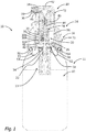
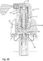
- Fig. 1 shows a section in the liquid dispenser 10 as a whole.
- the liquid dispenser 10 has a storage unit 11 which comprises a liquid storage 12 with an outlet valve arrangement 13.
- a discharge head 14 is placed on the storage unit 11 and is connected to the storage unit 11 in a latching manner by means of a fastening device 50.
- This The discharge head 14 for its part has an adapter unit 16 and a discharge unit 18.
- a discharge opening 38 is provided on this discharge unit 18.
- the discharge head 14 contains the majority of components of a metering device 20.
- This metering device 20 has one in the state of Fig. 1 maximally reduced pre-metering chamber 26 and a main metering chamber 32.
- the pre-metering chamber 26 and the main metering chamber 32 are provided in a chamber unit 74 which, among other things, provides an outer wall 56 and an end wall 58 as outer walls of the chamber unit 74.
- the pre-metering chamber 26 and the main metering chamber 32 are separated from one another by a wall unit 48, which can be displaced in the vertical direction in a piston-like manner with respect to the outer wall 56 and the end wall 58, thereby enlarging the pre-metering chamber 26 when the main metering chamber 32 is reduced and reducing the pre-metering chamber 26 when the main metering chamber is enlarged 32 permitted.
- This wall unit 48 represents a displaceable wall 32A on the side of the main metering chamber 32 and a displaceable wall 26A on the side of the pre-metering chamber 26.
- the wall unit 48 is acted upon by a spring device 40, in the present case in the form of a helical compression spring, in such a way that it moves downward and thus acts in the direction of a volumetric reduction of the pre-metering chamber 26.
- the pre-metering chamber 26 is connected to the liquid reservoir 12 by a supply channel 22, which extends partially within the reservoir unit 11 and is partially formed by a hollow control section 46 of the chamber unit 74.
- the pre-metering chamber 26 and the main metering chamber 32 are connected to one another by an intermediate channel 28, a valve also being provided in this intermediate channel 28, namely the intermediate valve 30.
- Liquid can flow from the main metering chamber 32 into a discharge channel 34, at the end of which the discharge opening 38 is provided.
- a discharge valve 36 in the discharge channel 34 opens as a function of pressure when there is sufficient pressure of the liquid in the discharge channel 34 and in the main metering chamber 32.
- the already mentioned chamber unit 74 is movable in a direction of movement 2 with respect to the liquid reservoir 12 and a base housing 70 of the discharge head, which is coupled to the storage unit 11 in a latching manner by the fastening device 50.
- an actuating unit 72 is also movable in the direction of movement 2, which on the one hand comprises the discharge unit 18 with the discharge channel 34 and discharge opening 38, which, however, additionally comprises a first control section 44 which extends into the chamber unit 74 and up to the intermediate valve 30 and is sealed on the outside with respect to the chamber unit 74 in the area of a sliding seal 45.
- An actuating handle 42 in the form of a pressure surface is provided on the upper side of the discharge head 14.
- the chamber unit 74 Since a high pressure is built up in the chamber unit 74 during the operation described below, the chamber unit 74 is secured against the end wall 88 being separated from the cylindrical outer wall 56 under the pressure effect. Securing is achieved in that the chamber unit 74 extends into the inner region 54 of a metallic cover 52 of the storage unit 11.
- the wall 62 of the cover 52 surrounding this area 54 prevents, indirectly via the wall of the base housing 70 serving as a securing element 60, a radial expansion of the outer wall 56, which would be necessary for a separation from the end wall 58.
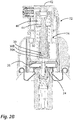
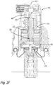
- FIG. 2A shows the state according to Fig. 1 .
- the operating handle 42 is in an upper end position, which at the same time represents the starting position.
- the intermediate valve 30 is opened because a spherical valve body 30B can freely detach from the valve seat 30A, and the main metering chamber 32 is thus connected to the pre-metering chamber 26.
- the supply valve 24 is closed under the impression of a valve spring of the storage unit 11.
- the pre-metering chamber 26 has its minimum volume in this state.
- the main metering chamber 32 has its maximum volume.
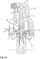
- FIG. 2B shows an intermediate state in which the actuation unit 72 is displaced so far down that a lower end of the first control section 44 has reached the spherical valve body 30B of the intermediate valve 30 and presses it against a corresponding valve seat 30A of the chamber unit 74.
- the intermediate valve 30 is now closed.
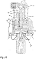
- FIG Figure 2C The continued depression of the operating unit 72 performs in FIG Figure 2C This makes clear that the chamber unit 74 is now depressed as a whole together with the actuating unit 72 via a force flow running through the valve body 30B. This is affected also the second control section 46, which acts on the supply valve 24 and opens it against the force of the valve spring there. Now liquid can be drawn from the liquid reservoir 12, which is designed as a pressure reservoir, along the in Figure 2C The line shown in dotted lines flows into the pre-metering chamber 26. A flow into the main metering chamber 32 is not possible due to the closed intermediate valve 30.
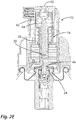
- Figure 2E shows the state with a maximally enlarged pre-metering chamber 26 and thus maximally reduced main metering chamber 32.
- the inflow of liquid from the liquid reservoir 12 ends in this state.
- the Figure 3A shows this state of the ready-to-operate dispenser 10 with the main metering chamber 32 completely filled with liquid.
- the sequence of movements of the described assemblies of the dispenser 10 corresponds in operation to that of the start-up according to FIG Figures 2A through 2H .
- the spring device 40 pushes the wall unit 48 down again and thus displaces the liquid from the pre-metering chamber 26 into the main metering chamber 32, so that the next subsequent actuation allows the liquid to be discharged again.
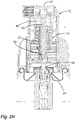
- the Fig. 4 shows a slightly modified alternative design. Unless explicitly stated otherwise below, the components are functionally identical to those of the design of the Figures 2A through 3B .
- the wall unit 48 and the chamber unit 74 are designed somewhat differently, so that the movable wall 26A of the pre-metering chamber 26 that generates pressure with respect to the direction of movement 2 is smaller than the movable wall 32A of the main metering chamber 32 that generates pressure with respect to the direction of movement 2.
- This has the effect that the increase in volume of the main metering chamber 32 when pumping liquid from the pre-metering chamber 26 into the main metering chamber 32 is greater than the decrease in volume of the pre-metering chamber 26.
- This causes liquid to be sucked back from the discharge channel 34 into the main metering chamber 32 during the pumping over so the risk of contamination of the liquid is reduced.
- the embodiment according to FIG Fig. 4 no discharge valve 36.
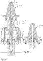
- the discharge unit 18 is designed differently than in the previous embodiments, since here the discharge unit 18 forms a nasal applicator.
- the design is in accordance with Figure 5A it is provided that the connection dimension of the discharge unit 18 on the first control section 44 corresponds to the connection dimension of the second control section 46 and the storage unit 11 matches. The effect is that the adapter unit 16 can be omitted from time to time.
- the discharge unit 18 configured with a nose applicator can also be coupled directly to the storage unit 11, such as Figure 5B made clear.
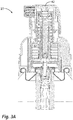
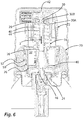
- the design according to Fig. 6 works in normal operation in accordance with the previous designs and is optimized in particular with regard to easier manufacturability.
- the essential difference is the structure of the chamber unit 74 with two chamber components 57, 59, both of which are each designed in a cup-like manner and are pushed into one another in the area of cylindrical outer walls. In the overlapping area, a positive locking connection is created, the locking lugs having a shape that opposes a non-destructive axial separation of the chamber components 57, 59.
- An expansion of the outer chamber component 57 and a resulting separation of the chamber components is prevented by the fact that the base unit 72 prevents the chamber component 57 from expanding in a row on the inside.
Landscapes
- Chemical & Material Sciences (AREA)
- Dispersion Chemistry (AREA)
- Engineering & Computer Science (AREA)
- Mechanical Engineering (AREA)
- Physics & Mathematics (AREA)
- Fluid Mechanics (AREA)
- General Physics & Mathematics (AREA)
- Containers And Packaging Bodies Having A Special Means To Remove Contents (AREA)
- Loading And Unloading Of Fuel Tanks Or Ships (AREA)
Description
Aus dem Stand der Technik sind Spender für Flüssigkeiten aus verschiedenen Bereichen bekannt. Solche Spender weisen einen Flüssigkeitsspeicher auf, innerhalb dessen eine Flüssigkeit vor dem Austrag gelagert wird, sowie eine Austragöffnung, durch die hindurch Flüssigkeit abgegeben werden kann. Gattungsgemäße Spender weisen weiterhin eine Dosiereinrichtung auf, die es gestattet, mit einer Betätigungsbewegung eine stets etwa gleichbleibende Flüssigkeitsmenge auszutragen.Dispensers for liquids from various fields are known from the prior art. Such dispensers have a liquid reservoir, within which a liquid is stored before discharge, and a discharge opening through which liquid can be dispensed. Generic dispensers also have a metering device which makes it possible to dispense an approximately constant amount of liquid with one actuation movement.
Unter einer Flüssigkeit im Sinne der Erfindung werden sowohl Flüssigkeiten geringer Viskosität ähnlich Wasser als auch höherviskose creme- oder gelartige Flüssigkeiten verstanden.A liquid in the context of the invention is understood to mean both liquids of low viscosity, similar to water, and of higher viscosity cream-like or gel-like liquids.
Gattungsgemäße wie auch erfindungsgemäße Flüssigkeitsspender können zum Austrag pharmazeutischer Flüssigkeiten verwendet werden, die bestimmungsgemäß insbesondere auf der Haut des Benutzers oder in Augen, Mund oder Nase appliziert werden. Sie können auch für kosmetische Flüssigkeiten verwendet werden, die insbesondere auf der Haut oder in das Haar eines Benutzers abgegeben werden. Weiterhin können gattungsgemäße wie auch erfindungsgemäße Spender zur dosierten Abgabe von Lebensmittel vorgesehen sein, wie beispielsweise Ketchup oder Mayonnaise. Auch technische Flüssigkeiten wie Maschinenöle, Lacke oder anderweitige Beschichtungsmaterialen können mit gattungsgemäßen und mit erfindungsgemäßen Spendern ausgetragen werden.Both generic and inventive liquid dispensers can be used to dispense pharmaceutical liquids which are intended to be applied in particular to the user's skin or in the eyes, mouth or nose. They can also be used for cosmetic liquids that are dispensed in particular onto the skin or into the hair of a user. Furthermore, generic and inventive dispensers can be provided for the dosed dispensing of food, such as ketchup or mayonnaise, for example. Technical liquids such as machine oils, lacquers or other coating materials can also be dispensed with generic and inventive dispensers.
Aus der
Im Kontext der vorliegenden Erfindung verwandte Dokumente sind beispielsweise die
Aufgabe der Erfindung ist es, einen Spender zur Verfügung zu stellen, der auf baulich einfache Art und Weise eine reproduzierbare Dosierung gestattet, wobei diese Dosierung vorzugsweise auch unter einem permanent anliegenden Flüssigkeitsdruck im Flüssigkeitsspeicher möglich sein soll.The object of the invention is to provide a dispenser which allows reproducible dosing in a structurally simple manner, this dosing preferably also being possible under a permanently applied liquid pressure in the liquid reservoir.
Erfindungsgemäß werden zur Lösung dieser Aufgabe ein Spender und ein Betriebsverfahren für einen Spender vorgeschlagen.According to the invention, a dispenser and an operating method for a dispenser are proposed to achieve this object.
Ein erfindungsgemäßer Spender verfügt entsprechend gattungsgemäßer Spender über einen Flüssigkeitsspeicher zur Lagerung der Flüssigkeit vor dem Austrag sowie über eine Austragöffnung, durch die die Flüssigkeit in eine Umgebung abgegeben werden kann. Er verfügt weiterhin über eine Dosiereinrichtung zur Abgabe einer definierten Flüssigkeitsmenge in Reaktion auf eine Betätigung des Spenders. Die Dosiereinrichtung ist zwischen dem Flüssigkeitsspeicher und der Austragöffnung vorgesehen und dafür ausgebildet, reproduzierbar übereinstimmende Flüssigkeitsmengen aus dem Flüssigkeitsspeicher auszutragen.A dispenser according to the invention has a liquid reservoir for storing the liquid prior to discharge and a discharge opening through which the liquid can be discharged into an environment. It also has a metering device for dispensing a defined amount of liquid in response to an actuation of the dispenser. The metering device is provided between the liquid reservoir and the discharge opening and is designed to discharge reproducibly matching amounts of liquid from the liquid reservoir.
Erfindungsgemäß ist die Dosiereinrichtung hierfür folgendermaßen gestaltet: Die Dosiereinrichtung verfügt über eine Vordosierkammer, die über einen Zufuhrkanal zumindest zeitweise mit dem Flüssigkeitsspeicher verbunden ist, sowie über eine Hauptdosierkammer, die über einen Zwischenkanal zumindest zeitweise mit der Vordosierkammer verbunden ist und über einen Austragkanal mit der Austragöffnung verbunden ist.According to the invention, the metering device is designed as follows: The metering device has a pre-metering chamber, which is at least temporarily connected to the liquid reservoir via a feed channel, as well as a main metering chamber, which is at least temporarily connected to the pre-metering chamber via an intermediate channel and to the discharge opening via a discharge channel connected is.
In der Vordosierkammer wird Flüssigkeit, die zuvor aus dem Flüssigkeitsspeicher in die Vordosierkammer geleitet wurde, vom Flüssigkeitsspeicher isoliert, wobei eine hierfür nutzbare Ventilanordnung vorgesehen sein kann, wie im Weiteren noch erläutert wird. Aus der Vordosierkammer wird die Flüssigkeit durch den Zwischenkanal in die Hauptdosierkammer weitergefördert und dort bezüglich des Flüssigkeitsaustausches von der Vordosierkammer und dem Flüssigkeitsspeicher isoliert. Auch hierfür kann eine Ventilanordnung vorgesehen sein, die im Weiteren noch erläutert wird.In the pre-metering chamber, liquid that was previously passed from the liquid reservoir into the pre-metering chamber is isolated from the liquid reservoir, wherein a valve arrangement that can be used for this purpose can be provided, as will be explained below. From the pre-metering chamber, the liquid is conveyed through the intermediate channel into the main metering chamber, where it is isolated from the pre-metering chamber and the liquid reservoir with regard to the fluid exchange. A valve arrangement, which will be explained below, can also be provided for this purpose.
Die Vordosierkammer und die Hauptdosierkammer weisen erfindungsgemäß jeweils eine verlagerbare Wandung auf, durch deren Verlagerung das jeweilige Kammervolumen veränderbar ist, wobei die verlagerbare Wandungen der Vordosierkammer und der Hauptdosierkammer derart miteinander wirkgekoppelt sind, dass eine Volumenvergrößerung der Vordosierkammer eine Volumenverkleinerung der Hauptdosierkammer verursacht.According to the invention, the pre-metering chamber and the main metering chamber each have a movable wall, the displacement of which can change the respective chamber volume, the movable walls of the pre-metering chamber and the main metering chamber being operatively coupled to one another in such a way that an increase in volume of the pre-metering chamber causes a volume reduction in the main metering chamber.
Bei einem erfindungsgemäßen Spender sind somit zwei Kammern, die Vordosierkammer und die Hauptdosierkammer, zwischen dem Flüssigkeitsspeicher und der Austragöffnung vorgesehen. Diese sind zumindest zeitweise derart miteinander verbunden, dass in einer Phase der Nutzung Flüssigkeit aus dem Flüssigkeitsspeicher in die Vordosierkammer strömen kann und in einer zweiten Phase der Nutzung Flüssigkeit aus der Vordosierkammer in die Hauptdosierkammer strömen kann. Wie im Weiteren noch erläutert wird, kann die jeweilige Steuerung der Phasen über Ventile erfolgen, die druckabhängig und/oder durch eine Betätigungshandhabe geschaltet öffnen und schließen können.In a dispenser according to the invention, two chambers, the pre-metering chamber and the main metering chamber, are thus provided between the liquid reservoir and the discharge opening. These are at least temporarily connected to one another in such a way that, in one phase of use, liquid can flow from the liquid reservoir into the pre-metering chamber and in a second phase of use, liquid can flow from the pre-metering chamber into the main metering chamber. As will be explained below, the respective control of the phases can take place via valves which can open and close depending on the pressure and / or switched by an actuating handle.
Durch die Wirkkoppelung der verlagerbaren Wandungen bedingen sich die Volumen der Vordosierkammer und der Hauptdosierkammer. Wird die Vordosierkammer durch Verlagerung ihrer verlagerbaren Wandung vergrößert, so führt dies zu einer Verringerung des Volumens der Hauptdosierkammer. Erfindungsgemäß wird dieser Zusammenhang genutzt, um aus der Hauptdosierkammer Flüssigkeit durch die Austragöffnung hindurch austragen zu können, indem eine Vergrößerung der Vordosierkammer bei darin einströmender Flüssigkeit und eine Verkleinerung der Hauptdosierkammer und damit ein Austrag stattfinden.The volumes of the pre-metering chamber and the main metering chamber are determined by the effective coupling of the displaceable walls. If the pre-metering chamber is enlarged by shifting its movable wall, this leads to a reduction in the volume of the main metering chamber. According to the invention, this relationship is used to be able to discharge liquid from the main metering chamber through the discharge opening by increasing the size of the pre-metering chamber when the liquid flows into it and reducing the size of the main metering chamber and thus a discharge.
Der Zufuhrkanal, der den Flüssigkeitsspeicher mit der Vordosierkammer verbindet und der Zwischenkanal, der die Vordosierkammer mit der Hauptdosierkammer verbindet, können abschnittsweise gemeinsam ausgeführt sein.The supply channel, which connects the liquid reservoir to the pre-metering chamber, and the intermediate channel, which connects the pre-metering chamber to the main metering chamber, can be designed jointly in sections.
Ein erfindungsgemäßer Spender ist üblicherweise als tragbarer Spender ausgebildet und verfügt daher vorzugsweise über einen Flüssigkeitsspeicher mit einem maximalen Flüssigkeitsvolumen von bis zu 1000 ml, vorzugsweise von bis zu 500 ml, insbesondere vorzugsweise von bis zu 250 ml.A dispenser according to the invention is usually designed as a portable dispenser and therefore preferably has a liquid reservoir with a maximum liquid volume of up to 1000 ml, preferably of up to 500 ml, in particular preferably of up to 250 ml.
Die Anwendungsfelder für einen erfindungsgemäßen Spender sind vielfältig. As besonders vorteilhaft wird die Verwendung im pharmazeutischen und kosmetischen Bereich angesehen. Im pharmazeutischen Bereich handelt es sich vorzugsweise um einen Spender zur Abgabe von Flüssigkeit auf der Haut eines Benutzers oder in dessen Augen, Nase oder Mund, so dass der Spender hierfür mit einem entsprechend angepassten Applikator versehen sein kann und mit einer pharmazeutischen Flüssigkeit befüllt sein kann. Im kosmetischen Bereich ist ein erfindungsgemäßer Spender insbesondere für die Abgabe von Gels und Lotionen auf die Haut sinnvoll verwendbar und in diesem Falle vorzugsweise mit einer kosmetischen Flüssigkeit, insbesondere einem kosmetisch wirkenden Gel oder einer kosmetisch wirkenden Lotion, befüllt.The fields of application for a dispenser according to the invention are diverse. The use in the pharmaceutical and cosmetic field is considered to be particularly advantageous. In the pharmaceutical field, it is preferably a dispenser for dispensing liquid on the skin of a user or in his eyes, nose or mouth, so that the dispenser can be provided with a suitably adapted applicator for this purpose and can be filled with a pharmaceutical liquid. In the cosmetic field, a dispenser according to the invention is particularly useful for dispensing gels and lotions onto the skin and in this case is preferably filled with a cosmetic liquid, in particular a cosmetically active gel or a cosmetically active lotion.
Neben der pharmazeutischen oder kosmetischen Verwendung wird auch die Verwendung für Lebensmittel und eine entsprechende Befüllung des Flüssigkeitsspeichers mit Ketchup, Mayonnaise, Speiseöl, Saucen oder Dressing erfindungsgemäß vorgeschlagen. Im Bereich technischer Flüssigkeiten werden insbesondere die Verwendung mit Lacken und anderen Beschichtungsmaterialien sowie Ölen sowie eine entsprechende Befüllung des Flüssigkeitsspeichers vorgeschlagen.In addition to the pharmaceutical or cosmetic use, the use for food and a corresponding filling of the liquid reservoir with ketchup, mayonnaise, edible oil, sauces or dressing is proposed according to the invention. In the field of technical fluids In particular, the use with paints and other coating materials as well as oils and a corresponding filling of the liquid reservoir are proposed.
Die jeweils mittels der Dosiereinrichtung zu dosierende Flüssigkeitsmenge hängt naturgemäß erheblich mit dem Anwendungsgebiet zusammen. Die zu dosierende Flüssigkeitsmenge der Dosiereinrichtung, die bauartbedingt von derVerlagerbarkeit der verlagerbaren Wandung der Hauptdosierkammer abhängt, beträgt vorzugsweise je nach Anwendungszweck zwischen 0,01 ml und 5 ml. Für viele Anwendungen wird ein Austragvolumen zwischen 0,1 ml und 3 ml, insbesondere zwischen 1 ml und 2 ml, als zweckmäßig angesehen.The amount of liquid to be dosed in each case by means of the dosing device naturally depends to a considerable extent on the area of application. The amount of liquid to be dosed in the dosing device, which depends on the design of the displaceability of the displaceable wall of the main dosing chamber, is preferably between 0.01 ml and 5 ml, depending on the application ml and 2 ml, considered appropriate.
Vorzugsweise ist eine Federeinrichtung vorgesehen, durch die die wirkgekoppelten verlagerbaren Wandungen derVordosierkammer und der Hauptdosierkammer permanent in Wirkungsrichtung einer Volumenverkleinerung der Vordosierkammer und einer Volumenvergrößerung der Hauptdosierkammer kraftbeaufschlagt sind.A spring device is preferably provided, by means of which the operatively coupled, displaceable walls of the pre-metering chamber and the main metering chamber are permanently acted upon in the direction of action of reducing the volume of the pre-metering chamber and increasing the volume of the main metering chamber.
Die genannte Federeinrichtung dient als Rückstellmittel. Eine Verlagerung der verlagerbaren Wandungen der Dosierkammern dahingehend, dass die Hauptdosierkammer verkleinert und die Vordosierkammer vergrößert wird, erfolgt in der beschriebenen Weise dadurch, dass Flüssigkeit in die Vordosierkammer strömt und unter dem beim Einströmen anliegenden Flüssigkeitsdruck die verlagerbaren Wandungen verlagert. Die beschriebene Federeinrichtung dient als Rückstellmittel, um die Wandungen der Dosierkammern derart zu verlagern, dass die Vordosierkammer volumetrisch verkleinert und die Hauptdosierkammer volumetrisch vergrößert wird. Die Federeinrichtung sollte dabei derart auf den Förderdruck beim Befüllen der Vordosierkammer abgestimmt sein, dass sie durch diesen Förderdruck komprimiert werden kann und einer Vergrößerung der Vordosierkammer somit nicht entgegensteht.The said spring device serves as a return means. The displaceable walls of the dispensing chambers are displaced in such a way that the main dispensing chamber is made smaller and the pre-dispensing chamber enlarged, in the manner described by the fact that liquid flows into the pre-dispensing chamber and the displaceable walls are displaced under the pressure of the liquid flowing in. The spring device described serves as a restoring means in order to displace the walls of the metering chambers in such a way that the pre-metering chamber is volumetrically reduced and the main metering chamber is volumetrically enlarged. The spring device should be matched to the delivery pressure when filling the pre-metering chamber in such a way that it can be compressed by this delivery pressure and thus does not prevent the pre-metering chamber from being enlarged.
Die Federeinrichtung erfüllt insbesondere vorzugsweise den Zweck, bei befüllter Vordosierkammer nach Isolation der Vordosierkammer vom Flüssigkeitsspeicher die Flüssigkeit aus der Vordosierkammer hinaus- und in die Hauptdosierkammer hineinzupumpen. Sie wirkt somit insbesondere vorzugsweise gleichsam zweifach. Durch die Vergrößerung der Hauptdosierkammer schafft sie im Falle einer Gestaltung der Austragöffnung mit einem Auslassventil einen Unterdruck und in der Vordosierkammer einen Überdruck, so dass die Flüssigkeit durch den Zwischenkanal von der Vordosierkammer in die Hauptdosierkammerströmen kann.In particular, the spring device preferably fulfills the purpose of pumping the liquid out of the pre-metering chamber and into the main metering chamber after the pre-metering chamber has been isolated from the liquid reservoir when the pre-metering chamber is filled. It thus acts, in particular, preferably in two ways. By enlarging the main metering chamber, if the discharge opening is designed with an outlet valve, it creates a negative pressure and an overpressure in the pre-metering chamber, so that the liquid can flow through the intermediate channel from the pre-metering chamber into the main metering chamber.
Im Zwischenkanal ist ein Zwischenventil vorgesehen, welches im geschlossenen Zustand das Einströmen von Flüssigkeit aus der Vordosierkammer in die Hauptdosierkammer verhindert und im offenen Zustand ermöglicht.An intermediate valve is provided in the intermediate channel which, in the closed state, prevents the flow of liquid from the pre-metering chamber into the main metering chamber and enables it in the open state.
Das Zwischenventil dient dem Zweck, in geöffnetem Zustand ein Umpumpen der Flüssigkeit aus der Vordosierkammer in die Hauptdosierkammer zu gestatten, jedoch bei Befüllung der Vordosierkammer und/oder während des Austrags zu verhindern, dass Flüssigkeit aus dem Flüssigkeitsspeicher direkt und unter Umgehung der Vordosierkammer in die Hauptdosierkammer strömt bzw. aus der Hauptdosierkammer nicht in Richtung der Austragöffnung, sondern in Richtung der Vordosierkammer abgegeben wird. Bei nicht betätigter Betätigungshandhabe ist das Ventil vorzugsweise geöffnet und wird erst durch Betätigen der Betätigungshandhabe geschlossen.The purpose of the intermediate valve is to allow the liquid to be pumped out of the pre-metering chamber into the main metering chamber when it is open, but to prevent fluid from the fluid reservoir from flowing directly into the main metering chamber when the pre-metering chamber is filled and / or during discharge, bypassing the pre-metering chamber flows or is discharged from the main metering chamber not in the direction of the discharge opening, but in the direction of the pre-metering chamber. When the actuating handle is not actuated, the valve is preferably open and is only closed by actuating the actuating handle.
Ebenso ist im Zufuhrkanal ein Zufuhrventil vorgesehen, welches im geschlossenen Zustand das Einströmen von Flüssigkeit aus dem Flüssigkeitsspeicher in die Vordosierkammer verhindert und im offenen Zustand ermöglicht.Likewise, a feed valve is provided in the feed channel, which in the closed state prevents the flow of liquid from the liquid reservoir into the pre-metering chamber and enables it in the open state.
Das Zufuhrventil dient dem Zweck, die Vordosierkammer gegenüber dem Flüssigkeitsspeicher zu isolieren, so dass zum einen ein gegebenenfalls im Flüssigkeitsspeicher herrschender Flüssigkeitsdruck nicht in einem unbenutzten Ruhezustand des Spenders auf die Flüssigkeit in der Vordosierkammer und der Hauptdosierkammer wirken kann. Zum anderen ist diese Isolation gegenüber dem Flüssigkeitsspeicher von Vorteil, um Flüssigkeit aus der Vordosierkammer in die Hauptdosierkammer fördern zu können, ohne dass diese in den Flüssigkeitsspeicher zurückströmt.The purpose of the supply valve is to isolate the pre-metering chamber from the liquid reservoir, so that, on the one hand, any liquid pressure in the liquid reservoir cannot act on the liquid in the pre-metering chamber and the main metering chamber when the dispenser is not in use. On the other hand, this insulation is advantageous compared to the liquid reservoir, in order to be able to convey liquid from the pre-dosing chamber into the main dosing chamber without it flowing back into the liquid reservoir.
Das Zufuhrventil ist vorzugsweise federbelastet und wird insbesondere vorzugsweise durch eine hierfür vorgesehene integrale Federeinrichtung permanent in Richtung seines geschlossenen Zustandes gedrückt. Es bedarf also einer gegen diese Federeinrichtung wirkenden Betätigungskraft, um es zu öffnen.The supply valve is preferably spring-loaded and, in particular, is preferably permanently pressed in the direction of its closed state by an integral spring device provided for this purpose. An actuating force acting against this spring device is therefore required in order to open it.
Der Spender verfügt vorzugsweise über eine Betätigungshandhabe, die zur Steuerung des Zufuhrventils und/oder des Zwischenventils mit mindestens einem dieser Ventile wirkverbunden ist. Die Betätigungshandhabe wirkt vorzugsweise auf mechanischem Wege auf das Zufuhrventil bzw. das Zwischenventil, so dass die Steuerung des jeweiligen Ventils ungeachtet eines im Spender bestehenden Flüssigkeitsdrucks ermöglicht ist.The dispenser preferably has an actuating handle which is operatively connected to at least one of these valves in order to control the supply valve and / or the intermediate valve. The actuating handle preferably acts mechanically on the supply valve or the intermediate valve, so that the control of the respective valve is made possible regardless of a liquid pressure existing in the dispenser.
Die Betätigungshandhabe wirkt insbesondere vorzugsweise auf das Zwischenventil in unmittelbarer mechanischer Weise. Insbesondere vorzugsweise wird das Zwischenventil durch Betätigen der Betätigungshandhabe, also üblicherweise durch Niederdrücken der Betätigungshandhabe, geschlossen. Das Zwischenventil verfügt insbesondere über einen Ventilsitz und einen Ventilkörper, wobei eines dieser beiden Elemente ortsfest zur Betätigungshandhabe ausgebildet sein kann. Bevorzugt ist jedoch eine Gestaltung, bei der ein Ventilkörper getrennt von der Betätigungshandhabe beweglich ist, jedoch mittels der Betätigungshandhabe in eine Schließposition gedrückt werden kann, in der er am Ventilsitz anliegt und dadurch den Zwischenkanal verschließt.In particular, the actuating handle acts preferably on the intermediate valve in a direct mechanical manner. In particular, the intermediate valve is preferably closed by actuating the actuating handle, that is to say usually by pressing down the actuating handle. The intermediate valve has in particular a valve seat and a valve body, one of which these two elements can be designed to be stationary for the actuating handle. However, a design is preferred in which a valve body is movable separately from the actuating handle, but can be pressed into a closed position by means of the actuating handle in which it rests against the valve seat and thereby closes the intermediate channel.
Durch Koppelung mit dem Zufuhrventil kann die Betätigungshandhabe steuern, ob Flüssigkeit aus dem Flüssigkeitsspeicher unter Druck in die Vordosierkammer gefördert wird und hierdurch mittelbar auch die Flüssigkeit in der Hauptdosierkammer druckbeaufschlagt wird.By coupling with the supply valve, the actuating handle can control whether liquid is conveyed from the liquid reservoir under pressure into the pre-metering chamber and whether the liquid in the main metering chamber is indirectly pressurized as a result.
Vorzugsweise ist eine gemeinsame Betätigungshandhabe am Spender vorgesehen, die zur Steuerung des Zufuhrventils und des Zwischenventils mit beiden Ventilen wirkverbunden ist, so dass mittels nur einer Betätigungshandhabe beide Ventile in unterschiedlichen Phasen der Nutzung des Spenders geöffnet bzw. geschlossen werden können. Alternativ kann auch eine mechanische Kopplung der genannten Ventile vorgesehen sein, bei der diese nicht in mechanischer Hinsicht durch eine Betätigungshandhabe geschaltet werden, sondern in Reaktion auf eine andere Zustandsänderung schalten, beispielsweise in Reaktion auf einen steigenden Druck im Flüssigkeitsspeicher.A common actuating handle is preferably provided on the dispenser, which is operatively connected to both valves to control the supply valve and the intermediate valve, so that both valves can be opened or closed in different phases of use of the dispenser by means of only one actuating handle. Alternatively, a mechanical coupling of the valves mentioned can also be provided, in which these valves are not switched mechanically by an actuating handle, but switch in response to another change in state, for example in response to an increasing pressure in the fluid reservoir.
Bei einer bevorzugten Gestaltung ist vorgesehen, dass die Wirkverbindungen zwischen der gemeinsamen Betätigungshandhabe einerseits und dem Zufuhrventil und dem Zwischenventil andererseits derart beschaffen ist, dass durch Betätigung der gemeinsamen Betätigungshandhabe das Zwischenventil geschlossen und das Zufuhrventil geöffnet wird.In a preferred embodiment, it is provided that the operative connections between the common actuating handle on the one hand and the supply valve and the intermediate valve on the other hand are such that the intermediate valve is closed and the supply valve is opened by actuating the common actuating handle.
Die Betätigungshandhabe ist demnach gemäß dieser Weiterbildung dafür ausgebildet, aus einem Ausgangszustand, in dem das Zufuhrventil geschlossen und das Zwischenventil geöffnet ist, einen zweiten Zustand der Dosiereinrichtung herzustellen, in der das Zwischenventil geschlossen und das Zufuhrventil geöffnet ist. In diesem zweiten Zustand kann Flüssigkeit aus dem Flüssigkeitsspeicher unter Druck in die Vordosierkammer gelangen, wird durch das Zwischenventil jedoch davon abgehalten, unmittelbar in die Hauptdosierkammer und/oderzurAustragöffnungzu strömen.According to this development, the actuating handle is accordingly designed to produce a second state of the metering device from an initial state in which the supply valve is closed and the intermediate valve is open, in which the intermediate valve is closed and the supply valve is open. In this second state, liquid can pass from the liquid reservoir under pressure into the pre-metering chamber, but is prevented by the intermediate valve from flowing directly into the main metering chamber and / or to the discharge opening.
Vorzugsweise ist dabei die Wirkverbindung zwischen der gemeinsamen Betätigungshandhabe oder einem anderen auslösenden Zustand wie einer Druckerhöhung im Flüssigkeitsspeicher einerseits und dem Zufuhrventil und dem Zwischenventil andererseits derart beschaffen, dass durch Betätigung der gemeinsamen Betätigungshandhabe zunächst das Zwischenventil geschlossen wird und durch anschließend, insbesondere durch fortgesetzte Betätigung der gemeinsamen Betätigungshandhabe, das Zufuhrventil geöffnet wird.The operative connection between the common actuating handle or another triggering state such as a pressure increase in the liquid reservoir on the one hand and the supply valve and the intermediate valve on the other hand is preferably such that the intermediate valve is initially closed by actuating the common actuating handle and then in particular through continued actuation of the common actuation handle, the supply valve is opened.
Die genannte Wirkverbindung ist also dafür ausgebildet, eine Art Verzögerung zu bewirken. Das Zwischenventil ist somit bereits geschlossen, wenn das Zufuhrventil geöffnet wird. Eine Möglichkeit hierfür liegt darin, beide Ventile, das Zufuhrventil und das Zwischenventil, in verschiedenen Betätigungsstellungen der Betätigungshandhabe zu schließen bzw. zu öffnen. Von besonderem Vorteil ist eine Gestaltung, bei der baulich ein Kausalzusammenhang geschaffen ist, der ein Öffnen des Zufuhrventils bei geöffnetem Zwischenventil unmöglich macht. Dies ist beispielsweise dadurch erzielbar, dass der Kraftfluss zwischen der Betätigungshandhabe und dem Zufuhrventil derart durch das Zwischenventil verläuft, dass dieses nur bei Anliegen seines Ventilkörpers am Ventilsitz des Zwischenventils und somit bei geschlossenen Zwischenventil den entsprechenden Kraftfluss schaffen kann.The said operative connection is thus designed to cause a kind of delay. The intermediate valve is thus already closed when the supply valve is opened. One possibility for this is to close or open both valves, the supply valve and the intermediate valve, in different operating positions of the operating handle. Particularly advantageous is a design in which a causal relationship is created structurally, which makes it impossible to open the supply valve when the intermediate valve is open. This can be achieved, for example, in that the force flow between the actuating handle and the supply valve runs through the intermediate valve in such a way that the intermediate valve can only create the corresponding force flow when its valve body is in contact with the valve seat of the intermediate valve and thus when the intermediate valve is closed.
Eine Möglichkeit zur Erzielung einer solchen Sequenz sieht vor, dass das Zwischenventil einen Ventilsitz und einem demgegenüber beweglichen Ventilkörper aufweist, wobei zur Steuerung dieses Ventilkörpers mittels der gemeinsamen Betätigungshandhabe ein fest mit der gemeinsamen Betätigungshandhabe verbundener erster Steuerabschnitt vorgesehen ist, der bei Betätigung der Betätigungshandhabe den Ventilkörper gegen den Ventilsitz presst, wobei der Ventilkörper separat vom ersten Steuerabschnitt ausgebildet sein kann oder auch ortsfest oder auch einstückig zu diesem ersten Steuerabschnitt vorgesehen sein kann.One possibility for achieving such a sequence provides that the intermediate valve has a valve seat and a valve body that is movable in relation to it, with a first control section firmly connected to the common operating handle being provided for controlling this valve body by means of the common operating handle, which controls the valve body when the operating handle is operated presses against the valve seat, wherein the valve body can be formed separately from the first control section or can also be provided in a stationary manner or also in one piece with this first control section.
Zusätzlich kann ein zweiter Steuerabschnitt zur Betätigung des Zufuhrventils vorgesehen sein, wobei dieser zweite Steuerabschnitt vorzugsweise ortsfest zum Ventilsitz des Zwischenventils angeordnet ist, so dass nach Schließen des Zwischenventils der zweite Steuerabschnitt über die gemeinsame Betätigungshandhabe zum Öffnen des Zufuhrventils verlagerbar ist.In addition, a second control section can be provided for actuating the feed valve, this second control section preferably being arranged in a stationary manner relative to the valve seat of the intermediate valve, so that after the intermediate valve has been closed, the second control section can be displaced via the common actuating handle for opening the feed valve.
Im einfachsten Falle werden die verlagerbaren Wandungen der Vordosierkammer und der Hauptdosierkammer durch eine verformbare Membran gebildet, deren eine Seite die Vordosierkammer begrenzt und deren andere Seite die Hauptdosierkammer begrenzt.In the simplest case, the displaceable walls of the pre-metering chamber and the main metering chamber are formed by a deformable membrane, one side of which delimits the pre-metering chamber and the other side of which delimits the main metering chamber.
Vorzugsweise handelt es sich jedoch bei den verlagerbaren Wandungen der Vordosierkammer und der Hauptdosierkammer um verschiebliche Wandungen, die in sich im Wesentlichen starr sind. Diese können mittels eines Getriebes verbunden sein, so dass die Bewegung einer der Wandungen nur bei gleichzeitiger Bewegung der anderen Wandung möglich ist.However, the displaceable walls of the pre-metering chamber and the main metering chamber are preferably displaceable walls which are essentially rigid in themselves. These can be connected by means of a gear so that the movement of one of the walls is only possible with simultaneous movement of the other wall.
Insbesondere können die beiden Wandungen hier ortsfest zueinander ausgebildet sein und durch eine gemeinsame Wandungseinheit gebildet sein, die in Art eines Kolbens verschiebbar ausgebildet ist. Diese Bauweise ist besonders einfach. Beide verlagerbaren Wandungen werden durch nur ein Bauteil zur Verfügung gestellt. Alternative Bauweisen sehen jedoch vor, dass die Wandungen an getrennten Bauteilen vorgesehen sind und wirkverbunden in unterschiedlichem Maße verlagert werden, beispielsweise durch das genannte zwischengeschaltete Getriebe. Insbesondere, wenn es gewünscht ist, die Druckbeaufschlagung der Flüssigkeit in der Hauptdosierkammer mit einem anderen Druck vorzunehmen als jenem im Flüssigkeitsspeicher und der Vordosierkammer, ist ein solches Getriebe eine zweckmäßige Realisierungsmöglichkeit.In particular, the two walls can be designed to be stationary with respect to one another and be formed by a common wall unit which is designed to be displaceable in the manner of a piston. This construction is particularly simple. Both movable walls are made available by just one component. Alternative construction methods, however, provide that the walls are provided on separate components and are relocated to different degrees in an operatively connected manner, for example by the aforementioned interposed gear. In particular, if it is desired to apply pressure to the liquid in the main metering chamber with a different pressure than that in the fluid reservoir and the pre-metering chamber, such a transmission is an expedient implementation option.
Aufgrund der einfachen Bauweise wird jedoch bevorzugt, dass ein zumindest im Wesentlichen identischer Druck in der Vordosierkammer und der Hauptdosierkammer durch eine gemeinsame Wandungseinheit geschaffen wird.Due to the simple construction, however, it is preferred that an at least substantially identical pressure in the pre-metering chamber and the main metering chamber is created by a common wall unit.
Hierbei ist es besonders bevorzugt, wenn die verlagerbare Wandungen der Vordosierkammer und der Hauptdosierkammer eine identische Größe bezogen auf die Bewegungsrichtung aufweisen, so dass eine Volumenverkleinerung der Vordosierkammer durch Verlagerung der Wandungseinheit eine Volumenvergrößerung der Hauptdosierkammer in gleichem Maße verursacht. Durch die identische Größe ist der Flüssigkeitsdruck bei geschlossenem Zwischenventil auf beiden Seiten, also in der Vordosierkammer und der Hauptdosierkammer, im Wesentlichen identisch. Lediglich die bereits genannte Federeinrichtung kann dazu führen, dass der sich in der Hauptdosierkammer einstellende Flüssigkeitsdruck etwas geringer als der Druck in derVordosierkammer ist.It is particularly preferred if the displaceable walls of the pre-metering chamber and the main metering chamber have an identical size in relation to the direction of movement, so that a reduction in volume of the pre-metering chamber by moving the wall unit causes the main metering chamber to increase in volume to the same extent. Due to the identical size, the liquid pressure is essentially identical when the intermediate valve is closed on both sides, i.e. in the pre-metering chamber and the main metering chamber. Only the spring device already mentioned can lead to the liquid pressure in the main metering chamber being somewhat lower than the pressure in the pre-metering chamber.
Alternativ können jedoch auch Gestaltungen vorgesehen sein, bei denen die verlagerbaren Wandungen unterschiedliche Größen aufweisen, was zu einer besonderen Charakteristik beim Flüssigkeits-übertrag aus der Vordosierkammer in die Hauptdosierkammer führt, wie im Weiteren noch erläutert ist.Alternatively, however, designs can also be provided in which the displaceable walls have different sizes, which leads to a special characteristic in the transfer of liquid from the pre-metering chamber into the main metering chamber, as will be explained below.
So kann die verlagerbare Wandung der Vordosierkammer größer oder kleiner als die verlagerbare Wandung der Hauptdosierkammer sein, so dass eine Volumenverkleinerung der Vordosierkammer durch Verlagerung der Wandungseinheit eine Volumenvergrößerung der Hauptdosierkammer in geringerem oder höherem Maße verursacht.The movable wall of the pre-metering chamber can be larger or smaller than the movable wall of the main metering chamber, so that a reduction in volume of the pre-metering chamber by moving the wall unit causes the main metering chamber to increase in volume to a lesser or greater extent.
Unterschiedliche Größen der verlagerbaren Wandung meinen in diesem Kontext die bezüglich der Druckerzeugung wirksamen Flächenabschnitte der jeweiligen verlagerbaren Wandung. Durch die unterschiedliche Größe können verschiedene Wirkungen erzielt werden, die fallweise gewünscht sein können. So kann insbesondere eine besondere Druckwirkung erzielt werden, bei der der Druck in der Hauptdosierkammer deutlich höher oder geringer als jener in der Vordosierkammer sein kann. Hierüber lässt sich beispielsweise ein besonders druckloser Flüssigkeitsaustrag oder ein durch besonders hohen Druck erzeugbares Sprühbild herstellen. Weiterhin kann hierdurch auch eine Rücksaugung von Flüssigkeit aus dem Austragkanal in die Hauptdosierkammer bewirkt werden, indem bei Verlagerung der verlagerbaren Wandungen die Volumenzunahme in der Hauptdosierkammer größer als die Volumenabnahme in der Vordosierkammer ist.Different sizes of the displaceable wall mean in this context the surface sections of the respective displaceable wall which are effective with regard to the generation of pressure. Due to the different size, different effects can be achieved, which may be desired on a case-by-case basis. In particular, a special pressure effect can be achieved in which the pressure in the main metering chamber can be significantly higher or lower than that in the pre-metering chamber. In this way, for example, a particularly pressureless liquid discharge or a spray pattern that can be generated by particularly high pressure can be produced. Furthermore, this can also cause liquid to be sucked back from the discharge channel into the main metering chamber, in that when the movable walls are displaced, the increase in volume in the main metering chamber is greater than the decrease in volume in the pre-metering chamber.
Die beschriebene erfindungsgemäße Gestaltung sieht vor, dass Flüssigkeit aus dem Flüssigkeitsspeicher unter Druck in die Vordosierkammer gefördert wird und durch die wechselwirkenden Wandungen hierdurch das Volumen der Hauptdosierkammer verringert und ein Austrag von Flüssigkeit verursacht wird.The described design according to the invention provides that liquid is conveyed from the liquid reservoir under pressure into the pre-metering chamber and the interacting walls thereby reduce the volume of the main metering chamber and cause liquid to be discharged.
Zur Erzeugung des Drucks zur Befüllung der Vordosierkammer und zur Verringerung des Volumens der Hauptdosierkammer verfügt der Spender als Flüssigkeitsspeicher vorzugsweise über einen Druckspeicher, der dafür ausgebildet ist, Flüssigkeit unter Überdruck zu speichern.To generate the pressure for filling the pre-metering chamber and to reduce the volume of the main metering chamber, the dispenser, as a fluid reservoir, preferably has a pressure reservoir which is designed to store fluid under excess pressure.
Ein solcher Druckspeicher führt dazu, dass die Flüssigkeit im Flüssigkeitsspeicher permanent und bereits im Lieferzustand an den Endkunden unter Druck steht. Dies ist beispielsweise durch eine permanent gespannte Federeinrichtung im Druckspeicher möglich, die auf einen Druckbeaufschlagungskolben wirkt. Andere Gestaltungen sehen das Vorhandensein von Treibgas im Flüssigkeitsspeicher vor. Auch möglich sind Gestaltungen mit einem Flüssigkeitsbeutel innerhalb des Druckspeichers, der von einer unter Überdruck stehenden Gasatmosphäre umgeben ist.Such a pressure accumulator means that the liquid in the liquid accumulator is permanently under pressure even when it is delivered to the end customer. This is possible, for example, by a permanently tensioned spring device in the pressure accumulator, which acts on a pressurizing piston. Other designs provide for the presence of propellant gas in the liquid reservoir. Designs with a liquid bag inside the pressure accumulator, which is surrounded by a gas atmosphere under excess pressure, are also possible.
Alternativ sind auch anderweitige Gestaltungen möglich, bei denen der Spender über eine Druckbeaufschlagungseinrichtung verfügt, mittels derer Flüssigkeit aus dem Flüssigkeitsspeicher zum Zwecke der Zuführung in die Vordosierkammer fallweise druckbeaufschlagbar ist.Alternatively, other designs are also possible in which the dispenser has a pressurization device, by means of which fluid from the fluid reservoir can occasionally be pressurized for the purpose of feeding it into the pre-metering chamber.
Eine solche Gestaltung könnte beispielsweise eine Pumpeinrichtung umfassen, mittels derer ein nicht zur langfristigen Druckbeaufschlagung vorgesehener Flüssigkeitsspeicher vorbereitend für einen nachfolgenden Austrag druckbeaufschlagt wird.Such a design could include, for example, a pumping device, by means of which a liquid reservoir that is not provided for long-term pressurization is pressurized in preparation for a subsequent discharge.
Grundsätzlich auch möglich ist die Koppelung einer Pumpeinrichtung zur Förderung von Flüssigkeit aus dem Flüssigkeitsspeicher in die Vordosierkammer mit der bereits genannten Betätigungshandhabe. Diese könnte somit zunächst die Druckbeaufschlagung von Flüssigkeit aus dem Flüssigkeitsspeicher bewirken und anschließend gegebenenfalls auf das Zwischenventil oder das Zufuhrventil und das Zwischenventil wirken. Auch eine Gestaltung, bei der die Druckbeaufschlagung des Flüssigkeitsspeichers manuell stattfindet, beispielsweise in Art einer Tube, und bei der gegebenenfalls die Steuerung der genannten Ventile, also des Zwischenventils und des Zufuhrventils mittelbar durch diese Druckbeaufschlagung des Flüssigkeitsspeichers erfolgt, ist denkbar.In principle, it is also possible to couple a pumping device for conveying liquid from the liquid reservoir into the pre-metering chamber with the aforementioned actuating handle. This could thus initially bring about the pressurization of liquid from the liquid reservoir and then possibly act on the intermediate valve or the supply valve and the intermediate valve. A design in which the pressurization of the liquid reservoir takes place manually, for example in the form of a tube, and in which the aforementioned valves, i.e. the intermediate valve and the supply valve are controlled indirectly by this pressurization of the liquid reservoir, is also conceivable.
Vorzugsweise verfügt der Spender über eine modulare Bauweise mit einer Speichereinheit und einem daran angekoppelten Austragkopf. Die Speichereinheit umfasst dabei den Flüssigkeitsspeicher sowie einen Auslass zur Abgabe der Flüssigkeit in Richtung des Austragkopfes. Der Austragkopf vereint die Vordosierkammer, die Hauptdosierkammer und die Austragöffnung in sich.The dispenser preferably has a modular design with a storage unit and a discharge head coupled to it. The storage unit comprises the liquid storage unit and an outlet for dispensing the liquid in the direction of the discharge head. The discharge head combines the pre-metering chamber, the main metering chamber and the discharge opening.
Im Falle einer Gestaltung mit einem Zufuhrventil im Zufuhrkanal zwischen Flüssigkeitsspeicher und Vordosierkammer ist dieses Zufuhrventil vorzugsweise Teil der Speichereinheit.In the case of a design with a supply valve in the supply channel between the liquid reservoir and the pre-metering chamber, this supply valve is preferably part of the storage unit.
Derartige Speichereinheiten, die einen Druckspeicher und ein Ventil umfassen, sind beispielsweise aus dem Bereich der Deodorants hinlänglich bekannt. Der Austragkopf mit Dosiereinrichtung erfindungsgemäßer Art könnte also mit einem handelsüblichen Druckspeicher mit einem solchen Ventil gekoppelt werden und hierdurch diesen um eine Dosiereinrichtung ergänzen. Das druckspeicherseitige Ventil bildet dann das Zufuhrventil im oben beschriebenen Sinne.Such storage units, which comprise a pressure accumulator and a valve, are sufficiently known, for example, from the field of deodorants. The discharge head with a metering device of the type according to the invention could therefore be coupled to a commercially available pressure accumulator with such a valve and thereby supplement it with a metering device. The valve on the pressure accumulator side then forms the supply valve in the sense described above.
Bei einer besonders vorteilhaften Gestaltung untergliedert sich der Austragkopf in eine Adaptereinheit und eine Austrageinheit. Die Adaptereinheit weist die Befestigungseinrichtung zur Befestigung an der Speichereinheit auf. Die Austrageinheit weist die Austragöffnung auf. Die Adaptereinheit und die Austrageinheit sind auf einfache Weise zusammengesteckt, wobei auch der Austragkanal von der Hauptdosierkammer zur Austragöffnung geschaffen wird. Insbesondere kann eine rein kraftschlüssig haltende Steckverbindung zwischen Adaptereinheit und Austrageinheit vorgesehen sein, aber auch Gestaltungen mit einer formschlüssig haltenden Steckverbindung, die beispielsweise mit Rastnasen auf Seiten der Adaptereinheit oder der Austrageinheit realisiert sein kann, sind möglich.In a particularly advantageous design, the discharge head is subdivided into an adapter unit and a discharge unit. The adapter unit has the fastening device for fastening to the storage unit. The discharge unit has the discharge opening. The adapter unit and the discharge unit are plugged together in a simple manner, the discharge channel also being created from the main metering chamber to the discharge opening. In particular, a purely frictional plug connection can be provided between the adapter unit and the discharge unit, but designs with a form-fitting plug connection, which can be implemented, for example, with latching lugs on the adapter unit or the discharge unit side, are also possible.
Bei einersolchen Gestaltung mit Adaptereinheit und Austrageinheit wird ein hohes Maß an Variabilität gewährleistet. Vorzugsweise ist die Austrageinheit mit oder ohne Adaptereinheit mit der Speichereinheit verbindbar, so dass auf Herstellerseite oder auf Kundenseite eine Anpassung an konkrete Bedürfnisse erfolgen kann. Die Austrageinheit ist mit der Adaptereinheit durch eine einfache Verbindung verbunden, die ohne weitere Demontage der Austrageinheit oder der Adaptereinheit möglich ist. Insbesondere kann es sich um eine rein kraftschlüssig haltende Steckverbindung handeln, wie sie bei Austragköpfen für Druckspeicher bereits üblich ist. Auch eine Gestaltung mit durch Aufstecken der Adaptereinheit erzielbarer Verrastung kann vorteilhaft sein.With such a design with adapter unit and discharge unit, a high degree of variability is guaranteed. The discharge unit is preferably with or without an adapter unit with the storage unit connectable so that an adaptation to specific needs can be made on the manufacturer's side or on the customer side. The discharge unit is connected to the adapter unit by a simple connection that can be made without further dismantling the discharge unit or the adapter unit. In particular, it can be a purely frictionally holding plug connection, as is already common in discharge heads for pressure accumulators. A design with latching that can be achieved by attaching the adapter unit can also be advantageous.
Die Speichereinheit weist vorzugsweise einen Deckel, insbesondere einen metallischen Deckel, auf, der den Flüssigkeitsspeicher in Richtung des Austragkopfes verschließt. Dieser Deckel ist vom Zufuhrkanal durchdrungen und verfügt über einen vertieften Bereich. Die Vordosierkammer und/oder die Hauptdosierkammer können durch eine außenseitig die jeweilige Kammer umgebende Außenwand und eine Stirnwand begrenzt sein, wobei die Außenwand und die Stirnwand durch zwei unterschiedliche Teile gebildet werden, die miteinander rastend verbunden sind. In einem solchen Fall ist es von Vorteil, wenn die Außenwand und/oder ein außenseitig der Außenwand angeordnetes Sicherungselement in den vertieften Bereich des Deckels hineinragen, so dass eine mechanische Trennung der Außenwand und der Stirnwand voneinander unter Wirkung des Drucks in der Vordosierkammer bzw. Hauptdosierkammer durch eine umlaufende Sicherungswand des Deckels unterbunden ist.The storage unit preferably has a cover, in particular a metallic cover, which closes the liquid reservoir in the direction of the discharge head. This cover is penetrated by the supply channel and has a recessed area. The pre-metering chamber and / or the main metering chamber can be delimited by an outer wall surrounding the respective chamber on the outside and an end wall, the outer wall and the end wall being formed by two different parts which are connected to one another in a latching manner. In such a case, it is advantageous if the outer wall and / or a securing element arranged on the outside of the outer wall protrude into the recessed area of the cover, so that a mechanical separation of the outer wall and the end wall from one another under the action of the pressure in the pre-metering chamber or main metering chamber is prevented by a circumferential securing wall of the cover.
Der genannte Deckel der Speichereinheit ist in ähnlicher Weise schon von bekannten Speichereinheiten bekannt. Üblicherweise handelt es sich um einen metallischen Deckel, der auf der im Wesentlichen zylindrischen Mantelwandung des Druckspeichers durch eine Crimpverbindung befestigt wird. Die hier vorgeschlagene Gestaltung sieht vor, dass die von diesem Deckel geschaffene Vertiefung genutzt wird, um formschlüssig zu verhindern, dass die genannte Außenwand und die genannte Stirnwand sich trennen. Die Gefahr einer solchen Trennung ist durch den je nach Ausgestaltung hohen Druck gegeben, mit der die Flüssigkeit aus dem Flüssigkeitsspeicher in die Vordosierkammer strömt.The mentioned cover of the storage unit is already known in a similar manner from known storage units. It is usually a metallic cover that is attached to the essentially cylindrical casing wall of the pressure accumulator by means of a crimp connection. The design proposed here provides that the recess created by this cover is used in order to prevent, in a form-fitting manner, that the named outer wall and the named end wall separate. The risk of such a separation is given by the high pressure with which the liquid flows from the liquid reservoir into the pre-metering chamber, depending on the configuration.
Es sind sowohl Gestaltungen möglich, bei denen keinerlei weitere Elemente zwischen der Sicherungswand des Deckels und der Außenwand der Vordosierkammer oder Hauptdosierkammer vorhanden sind. Es kann jedoch auch ein dazwischen liegendes Sicherungselement vorgesehen sein. Dies ist insbesondere dann zweckmäßig, wenn die Außenwand und die Stirnwand bestimmungsgemäß bei der Betätigung des Spenders axial verlagert werden, wie im Weiteren noch erläutert ist. Das dazwischen liegende Sicherungselement kann in einem solchen Fall gewährleisten, dass eine Fügestelle zwischen Außenwand und Stirnwand auch dann gesichert wird, wenn die Fügestelle axial aus der Vertiefung des Deckels herausbewegt wurde.Both designs are possible in which no further elements are present between the securing wall of the cover and the outer wall of the pre-metering chamber or main metering chamber. However, a securing element lying in between can also be provided. This is particularly useful when the outer wall and the end wall are axially displaced as intended when the dispenser is operated, as will be explained below. In such a case, the securing element located in between can ensure that a joint between the outer wall and the end wall is also secured when the joint has been moved axially out of the recess in the cover.
Eine vorteilhafte Gestaltung sieht vor, dass die Vordosierkammer und/oder die Hauptdosierkammer zwei gemeinsame Kammerbauteile begrenzt werden, die in einer axialen Richtung miteinander verbunden sind und die vorzugsweise ortsfest zum zweiten Steuerabschnitt vorgesehen sind.An advantageous design provides that the pre-metering chamber and / or the main metering chamber are delimited by two common chamber components which are connected to one another in an axial direction and which are preferably provided in a stationary manner with respect to the second control section.
Als baulich vorteilhaft hat sich neben der oben beschriebenen Gestaltung unter Nutzung des Deckels als Sicherung eine Gestaltung herausgestellt, bei der die Kammerbauteile jeweils einen zylindrischen Außenabschnitt umfassen, wobei die beiden Außenabschnitte überlappend ineinander geschoben sind. Hierdurch wird ein besonders hohes Maß an Stabilität erreicht. Die überlappenden Bereiche von vorzugsweise einigen Millimetern Überlappungslänge sind darüber hinaus gut für die Anordnung von Rastelementen zur Verrastung der Kammerbauteile geeignet.In addition to the design described above using the cover as a safety device, a design in which the chamber components each comprise a cylindrical outer section, the two outer sections being pushed into one another in an overlapping manner, has proven to be structurally advantageous. This achieves a particularly high degree of stability. The overlapping areas of preferably a few millimeters overlap length are also well suited for the arrangement of locking elements for locking the chamber components.
Weiterhin vorteilhaft ist es, wenn ein Basisgehäuse des Austragkopfes einen der genannten Außenabschnitte derart umgibt, dass eine Aufweitung des Außenabschnittes begrenzt wird, um einer Trennung der Kammerbauteile entgegenzuwirken. Somit kann die vollständige Trennung der Kammerbauteile verhindert werden, Zwar ist eine Leckage möglich, aber eine möglicherweise verletzungsgefährdende vollständige Trennung der Kammerbauteile wird wirksam verhindert.It is also advantageous if a base housing of the discharge head surrounds one of the named outer sections in such a way that an expansion of the outer section is limited in order to counteract a separation of the chamber components. In this way, the complete separation of the chamber components can be prevented. Although a leak is possible, a complete separation of the chamber components, which may endanger injury, is effectively prevented.
Der Aufbau eines erfindungsgemäßen Spenders sieht vorzugsweise vor, dass der Austragkopf über ein Basisgehäuse verfügt, welches über die Befestigungseinrichtung ortsfest mit dem Flüssigkeitsspeicher verbunden ist. Der Austragkopf verfügt vorzugsweise über eine linear gegenüber dem genannten Basisgehäuse bewegliche Betätigungseinheit, die die Betätigungshandhabe umfasst, sowie über eine linear gegenüber dem Basisgehäuse und der Betätigungseinheit bewegliche Kammereinheit, die die Außenwandung der Vordosierkammer und/oder der Hauptdosierkammer bildet.The construction of a dispenser according to the invention preferably provides that the discharge head has a base housing which is connected in a stationary manner to the liquid reservoir via the fastening device. The discharge head preferably has an actuating unit which is linearly movable with respect to the named base housing and which comprises the operating handle, as well as a chamber unit which is linearly movable with respect to the base housing and the actuating unit and which forms the outer wall of the predosing chamber and / or the main dosing chamber.
Das genannte Basisgehäuse verbleibt stets ortsfest zum Flüssigkeitsspeicher bzw. zu einem Gehäuse des Flüssigkeitsspeichers. Demgegenüber ist die Betätigungshandhabe verlagerbar, um ein Öffnen und Schließen des Zwischenventils zu ermöglichen und um weiterhin das Zufuhrventil öffnen oder schließen zu können.The named base housing always remains stationary with respect to the liquid reservoir or to a housing of the liquid reservoir. In contrast, the actuating handle can be displaced in order to enable the intermediate valve to be opened and closed and in order to continue to be able to open or close the supply valve.
Die verlagerbare Ausgestaltung der Kammereinheit ist nicht zwingend, jedoch vorteilhaft. Sie erlaubt es, unmittelbar die Kammereinheit bzw. einen hierzu ortsfesten Betätigungsabschnitt zu nutzen, um das Zufuhrventil zu öffnen bzw. zu schließen. Dies hat den Vorteil, dass im Bereich der Vordosierkammer keinerlei Gleitdichtung zwischen dem Flüssigkeitsspeicher und der Vordosierkammer vorgesehen sein muss, was insbesondere deswegen von Vorteil ist, da hier hohe Drücke herrschen und sich gezeigt hat, dass Gleitdichtungen an dieser Stelle nur aufwendig in ausreichender Sicherheit realisierbar sind.The displaceable design of the chamber unit is not mandatory, but advantageous. It allows the chamber unit or an actuating section which is stationary for this purpose to be used directly in order to open or close the supply valve. This has the advantage that in the area of the pre-metering chamber no sliding seal has to be provided between the liquid reservoir and the pre-metering chamber, which is particularly advantageous because high pressures prevail here and are shown has the fact that sliding seals can only be implemented with sufficient security at this point with great effort.
Nichtsdestotrotz kann bei einer alternativen Gestaltung vorgesehen sein, dass die Kammereinheit ortsfest zum Basisgehäuse vorgesehen ist. Dann aber ist es bei einer Gestaltung, bei der die Betätigungshandhabe das Zwischenventil und das Zufuhrventil schalten soll, erforderlich, dass der entsprechende Betätigungsabschnitt zum Schalten des Zufuhrventils gegenüber der Kammereinheit verlagerbar ist, was mit dem beschriebenen Problem der dort dann erforderlichen Gleitdichtung einhergeht. Wenn jedoch der hierfür erforderliche Aufwand angemessen erscheint oder aufgrund nur geringer Betriebsdrücke des erfindungsgemäßen Spenders unproblematisch ist, so kann auch diese Ausgestaltung zweckmäßig sein.Nonetheless, in an alternative configuration, it can be provided that the chamber unit is provided in a stationary manner with respect to the base housing. In a design in which the actuating handle is to switch the intermediate valve and the supply valve, however, it is necessary that the corresponding actuating section for switching the supply valve can be displaced relative to the chamber unit, which is associated with the described problem of the sliding seal then required there. However, if the effort required for this appears appropriate or is unproblematic due to only low operating pressures of the dispenser according to the invention, then this configuration can also be expedient.
Der Spender weist bei einer möglichen Ausgestaltung im Austragkanal ein Austragventil auf, welches in Abhängigkeit des Drucks der von der Hauptdosierkammer einströmenden Flüssigkeit öffnet.In one possible embodiment, the dispenser has a discharge valve in the discharge channel which opens as a function of the pressure of the liquid flowing in from the main metering chamber.
Das Austragventil ist vorzugsweise ein druckabhängig schaltendes Ventil, welches bei ausreichendem Druck in der Hauptdosierkammer und damit in einem zur Austragöffnung führenden Austragkanal öffnet. Hierdurch lässt sich eine spezifisch angepasste Austragcharakteristik erzielen, beispielsweise ein bestimmtes Sprühbild. Zudem ist ein solches Ventil zweckmäßig, um die im Austragkanal verbliebene Flüssigkeit gegenüber einer Umgebung zu isolieren und somit Kontaminationen zu verhindern. Des Weiteren ist das Ventil auch von Vorteil, um zum Zwecke des Umpumpens von Flüssigkeit aus der Vordosierkammer in die Hauptdosierkammer die Entstehung eines hierfür vorteilhaften Unterdrucks in der Hauptdosierkammer zu bewirken. Durch das genannte Austragventil wird verhindert, dass dieser Unterdruck durch aus einer Umgebung durch die Austragöffnung einströmende Luft unterbunden wird.The discharge valve is preferably a pressure-dependent switching valve which opens when there is sufficient pressure in the main metering chamber and thus in a discharge channel leading to the discharge opening. In this way, a specifically adapted discharge characteristic can be achieved, for example a specific spray pattern. In addition, such a valve is useful in order to isolate the liquid remaining in the discharge channel from an environment and thus to prevent contamination. Furthermore, the valve is also advantageous in order to bring about the creation of an advantageous negative pressure in the main metering chamber for the purpose of pumping liquid from the pre-metering chamber into the main metering chamber. The aforementioned discharge valve prevents this negative pressure from being suppressed by air flowing in from the environment through the discharge opening.
Neben dem Spender selbst betrifft die Erfindung auch ein Betriebsverfahren für einen solchen Spender. Bei diesem Verfahren sind die folgenden Schritte vorgesehen. Zunächst wird die Vordosierkammer durch den Zufuhrkanal mit druckbeaufschlagter Flüssigkeit aus dem Flüssigkeitsspeicher befüllt, wobei sie dabei durch druckbedingte Verlagerung der verlagerbaren Wandung der Vordosierkammer ihr maximales Volumen einnimmt und die Hauptdosierkammer durch hiervon verursachter Verlagerung der verlagerbaren Wandung ihr minimales Volumen einnimmt. Ausgehend von der befüllten Vordosierkammer wird dann die Flüssigkeit aus der Vordosierkammer unter Verlagerung der verlagerbaren Wandung durch den Zwischenkanal in die Hauptdosierkammer gefördert, bis die Hauptdosierkammer ihr maximales Volumen einnimmt und die Vordosierkammer ihr minimales Volumen einnimmt. Im Zuge nochmaliger Befüllung der Vordosierkammer durch den Zufuhrkanal mitdruckbeaufschlagter Flüssigkeit aus dem Flüssigkeitsspeicher werden die verlagerbaren Wandungen der Vordosierkammer und der Hauptdosierkammer dann wiederum verlagert, so dass das Volumen der Hauptdosierkammer verringert wird und die Flüssigkeit aus der Hauptdosierkammer durch die Austragöffnung hindurch ausgetragen wird.In addition to the dispenser itself, the invention also relates to an operating method for such a dispenser. This procedure includes the following steps. First of all, the pre-metering chamber is filled with pressurized liquid from the liquid reservoir through the supply channel, whereby it assumes its maximum volume due to pressure-related displacement of the displaceable wall of the pre-dispensing chamber and the main metering chamber assumes its minimum volume due to the displacement of the displaceable wall caused by this. Starting from the filled pre-metering chamber, the liquid is then conveyed from the pre-metering chamber with the displacement of the movable wall through the intermediate channel into the main metering chamber until the main metering chamber occupies its maximum volume and the pre-metering chamber occupies its minimum volume. When the pre-metering chamber is filled again through the supply channel of pressurized fluid from the fluid reservoir, the displaceable walls of the pre-metering chamber and the main metering chamber are then shifted again so that the volume of the main metering chamber is reduced and the liquid is discharged from the main metering chamber through the discharge opening.
Weitere Vorteile und Aspekte der Erfindung ergeben sich aus den Ansprüchen und aus der nachfolgenden Beschreibung von bevorzugten Ausführungsbeispielen der Erfindung, die nachfolgend anhand der Figuren erläutert sind.
-
Fig. 1 zeigt einen erfindungsgemäßen Spender in einer Gesamtdarstellung in geschnittener Ansicht. -
Fig. 2A bis 2H zeigen einen Teilbereich des Spenders umfassend den oberen Teil seiner Speichereinheit sowie seinen Austragkopf, wobei verschiedene Stadien bei der Inbetriebnahme des Spenders verdeutlicht werden. -
Fig. 3A und3B verdeutlichen die Funktionsweise des Spenders nach Inbetriebnahme. -
Fig. 4 zeigt eine alternative Gestaltung des Austragkopfes. -
Fig. 5A und 5B zeigen eine weitere mögliche Gestaltung des Austragkopfes und die Verwendbarkeit von dessen Austrageinheit ohne Adaptereinheit. -
Fig. 6 zeigt eine weitere alternative Gestaltung des Austragkopfes.
-
Fig. 1 shows a dispenser according to the invention in an overall representation in a sectional view. -
Figures 2A through 2H show a partial area of the dispenser including the upper part of its storage unit and its discharge head, with different stages in the commissioning of the dispenser being illustrated. -
Figure 3A and3B illustrate how the dispenser works after it has been put into operation. -
Fig. 4 shows an alternative design of the discharge head. -
Figures 5A and 5B show another possible design of the discharge head and the usability of its discharge unit without an adapter unit. -
Fig. 6 shows a further alternative design of the discharge head.
Der Flüssigkeitsspender 10 verfügt über eine Speichereinheit 11, die einen Flüssigkeitsspeicher 12 mit einer Auslassventilanordnung 13 umfasst. Auf die Speichereinheit 11 ist ein Austragkopf 14 aufgesetzt und mittels einer Befestigungseinrichtung 50 verrastend mit der Speichereinheit 11 verbunden. Dieser Austragkopf 14 verfügt seinerseits über eine Adaptereinheit 16 und eine Austrageinheit 18. An dieser Austrageinheit 18 ist eine Austragöffnung 38 vorgesehen.The
Der Austragkopf 14 beinhaltet die überwiegende Zahl von Komponenten einer Dosiereinrichtung 20. Diese Dosiereinrichtung 20 verfügt über eine im Zustand der
Die Vordosierkammer 26 ist mit dem Flüssigkeitsspeicher 12 durch einen Zufuhrkanal 22 verbunden, der sich teilweise innerhalb der Speichereinheit 11 erstreckt und teilweise durch einen hohlen Steuerabschnitt 46 der Kammereinheit 74 gebildet wird. Innerhalb dieses Zufuhrkanals 22 ist ein Zufuhrventil 24 vorgesehen, welches Teil der Ventilanordnung 13 der Speichereinheit 11 ist. Die Vordosierkammer 26 und die Hauptdosierkammer 32 sind durch einen Zwischenkanal 28 miteinander verbunden, wobei auch in diesem Zwischenkanal 28 ein Ventil vorgesehen ist, nämlich das Zwischenventil 30.The
Aus der Hauptdosierkammer 32 kann Flüssigkeit in einen Austragkanal 34 strömen, an dessen Ende die Austragöffnung 38 vorgesehen ist. Ein Austragventil 36 im Austragkanal 34 öffnet druckabhängig bei ausreichendem Druck der Flüssigkeit im Austragkanal 34 und in der Hauptdosierkammer 32.Liquid can flow from the
Die bereits genannte Kammereinheit 74 ist in einer Bewegungsrichtung 2 gegenüber dem Flüssigkeitsspeicher 12 und einem Basisgehäuse 70 des Austragkopfes, welches an der Speichereinheit 11 durch die Befestigungseinrichtung 50 rastend angekoppelt ist, beweglich. Gegenüber dem Basisgehäuse 70 und der Kammereinheit 74 ist auch eine Betätigungseinheit 72 in der Bewegungsrichtung 2 beweglich, die zum einen die Austrageinheit 18 mitsamt Austragkanal 34 und Austragöffnung 38 umfasst, die jedoch zusätzlich einen ersten Steuerabschnitt 44 umfasst, der sich in die Kammereinheit 74 und bis zum Zwischenventil 30 erstreckt und außenseitig gegenüber der Kammereinheit 74 im Bereich einer Gleitdichtung 45 abgedichtet ist. An der Oberseite des Austragkopfes 14 ist eine Betätigungshandhabe 42 in Form einer Druckfläche vorgesehen.The already mentioned
Da in der Kammereinheit 74 beim nachfolgend beschriebenen Betrieb ein hoher Druck aufgebaut wird, ist die Kammereinheit 74 dagegen gesichert, dass die Stirnwand 88 unter der Druckwirkung von der zylindrischen Außenwand 56 getrennt wird. Die Sicherung wird dadurch erzielt, dass die Kammereinheit 74 sich bis in den inneren Bereich 54 eines metallischen Deckels 52 der Speichereinheit 11 erstreckt. Die diesen Bereich 54 umgebende Wand 62 des Deckels 52 verhindert mittelbar über die als Sicherungselement 60 dienende Wandung des Basisgehäuses 70 eine radiale Aufweitung der Außenwand 56, die für eine Trennung von der Stirnwand 58 erforderlich wäre.Since a high pressure is built up in the
Ausgehend vom Spender 10 im Lieferzustand der
Ausgehend von dieser Ausgangsstellung wird die Betätigungshandhabe 42 mitsamt der gesamten Betätigungseinheit 72 in Bewegungsrichtung 2 niedergedrückt, wodurch es auch zu einer Verlagerung des ersten Steuerabschnitts 44 in gleichem Maße nach unten kommt.
Das fortgesetzte Niederdrücken der Betätigungseinheit 72 führt in der durch
Wie
Wenn nun die Betätigungshandhabe 42 losgelassen wird, so führt dies dazu, dass entsprechend der Darstellung der
Da bei der Inbetriebnahme des Spenders 10 die Hauptdosierkammer noch mit Luft befüllt war, muss vor einem tatsächlichen Austrag zunächst diese Luft verdrängt werden. Bei dem in den
Die
Wenn ausgehend vom unbetätigten betriebsbereiten Zustand der
Sobald die Betätigungshandhabe 42 nach erfolgtem Austrag wieder losgelassen wird, drückt die Federeinrichtung 40 die Wandungseinheit 48 wieder nach unten und verdrängt somit die Flüssigkeit aus der Vordosierkammer 26 in die Hauptdosierkammer 32, so dass mit der darauffolgenden nächsten Betätigung wiederum Flüssigkeit ausgetragen werden kann.As soon as the
Die
Bei der Ausgestaltung gemäß der
Bis auf die genannten Aspekte ist die bauliche Ausgestaltung der
Die Gestaltung gemäß
Claims (14)
- Dispenser (10) for discharging liquids, having the following features:a. the dispenser (10) includes a liquid reservoir (12) for storing the liquid prior to discharging, andb. the dispenser (10) includes a discharge opening (38) through which the liquid can be dispensed into an environment,c. the dispenser (10) includes a metering installation (20) for discharging a defined liquid quantity as a reaction to an activation of the dispenser (10), wherein the metering installation at the entry side is connected to the liquid reservoir (12) and at the exit side is connected to the discharge opening (38), andd. the metering installation (20) includes a pre-metering chamber (26) which by way of an infeed duct (22) is connected to the liquid reservoir (12), ande. the metering installation includes a main metering chamber (32) which by way of an intermediate duct (28) is connected to the pre-metering chamber (26) and by way of a discharge duct (34) is connected to the discharge opening (38), andf. the pre-metering chamber (26) and the main metering chamber (32) each have a repositionable wall (26A, 32A), the respective chamber volume being variable by the repositioning of said wall (26A, 32A), andg. the repositionable walls (26A, 32A) of the pre-metering chamber (26) and of the main metering chamber (32) are operatively coupled in such a manner that a volumetric enlargement of the pre-metering chamber (26) causes a volumetric reduction of the main metering chamber (32), andh. an infeed valve (24) which in the closed state prevents and in the opened state enables the inflow of liquid from the liquid reservoir (12) into the pre-metering chamber (26) is provided in the infeed duct (22),
characterized by the following feature:i. an intermediate valve (30) which in the closed state prevents and in the opened state enables the inflow of liquid from the pre-metering chamber (26) into the main metering chamber (32) is provided in the intermediate duct (28). - Dispenser (10) for discharging liquids according to Claim 1, having the following additional feature:a. a spring installation (40) by way of which the operatively coupled walls (26A, 32A) of the pre-metering chamber (26) and of the main metering chamber (32) are permanently impinged with a force in the effective direction of a volumetric reduction of the pre-metering chamber (26) and a volumetric enlargement of the main metering chamber (32) is provided.
- Dispenser (10) for discharging liquids according to Claim 2, having the following additional feature:a. an activation handle (42) which for controlling the infeed valve (24) and/or the intermediate valve (30) is operatively connected to at least one of said valves (24, 30) is provided,
in particular having the additional feature:b. the activation handle (42) acts mechanically on the infeed valve (24) or the intermediate valve (30) respectively, so that the control of the respective valve (24, 30) is enabled irrespectively of a liquid pressure prevailing in the dispenser (10). - Dispenser (10) for discharging liquids according to Claim 3, having the following additional features:a. a common activation handle (42) which for controlling the infeed valve (24) and the intermediate valve (30) is operatively connected to both valves (24, 30) is provided, andb. the operative connections between the common activation handle (42), on the one hand, and the infeed valve (24) and the intermediate valve (30), on the other hand, are specified in such a manner that the intermediate valve (30) is closed and the infeed valve (24) is opened by activating the common activation handle (42) .
- Dispenser (10) for discharging liquids according to Claim 4, having the following additional feature:a. the operative connections between the common activation handle (42), on the one hand, and the infeed valve (24) and the intermediate valve (30), on the other hand, are specified in such a manner that the intermediate valve (30) is initially closed by activating the common activation handle (42), and the infeed valve (24) is opened by the subsequent, continuing, activation of the common activation handle,
in particular having the following additional features:b. the intermediate valve (30) has a valve seat (30A) and a valve body (30B) that is movable in relation thereto, wherein for controlling said valve body (30B) by means of the common activation handle (42) a first control portion (44) which is fixedly connected to the common activation handle (42) and which when activating the activation handle (42) presses the valve body (30B) against the valve seat (30A) is provided, andc. a second control portion (46) for activating the infeed valve (24) is provided, wherein said second control portion (46) is disposed so as to be locationally fixed in relation to the valve seat (30A) of the intermediate valve such that, after the closing of the intermediate valve (30), the second control portion (46) for opening the infeed valve (24) is repositionable by way of the common activation handle (42). - Dispenser (10) for discharging liquids according to one of the preceding claims, having the following additional feature:a. the repositionable walls (26A, 32A) of the pre-metering chamber (26) and of the main metering chamber (32) are configured as displaceable walls which are mutually locationally fixed and, on account thereof, form a common wall unit (48),
preferably having one of the following additional features:b. the repositionable walls (26A, 32A) of the pre-metering chamber (26) and of the main metering chamber (32) are of identical size such that a volumetric reduction of the pre-metering chamber (26) by repositioning the wall unit (48) to the same extent causes a volumetric enlargement of the main metering chamber (32), orc. the repositionable wall (26A) of the pre-metering chamber (26) is smaller than the repositionable wall (32A) of the main metering chamber (32) such that a volumetric reduction of the pre-metering chamber (26) by repositioning the wall unit (48) causes to a greater extent a volumetric enlargement of the main metering chamber (32), ord. the repositionable wall (26A) of the pre-metering chamber (26) is larger than the repositionable wall (32A) of the main metering chamber (32) such that a volumetric reduction of the pre-metering chamber (26) by repositioning the wall unit (48) causes to a lesser extent a volumetric enlargement of the main metering chamber (32). - Dispenser (10) for discharging liquids according to one of the preceding claims, having one of the following additional features:a. the dispenser (10) as a liquid reservoir (12) includes a pressure reservoir which is configured for storing liquid at a positive pressure, orb. the dispenser includes a pressure-impingement installation by means of which liquid from the liquid reservoir for the purpose of feeding into the pre-metering chamber is capable of being impinged with pressure.
- Dispenser (10) for discharging liquids according to one of the preceding claims, having the following additional features:a. the dispenser (10) includes a storage unit (11) which comprises the liquid reservoir (12), andb. the dispenser includes a discharge head (14) which by means of a fastening installation (50) is fastened to the storage unit (11) and which comprises the pre-metering chamber (26), the main metering chamber (32), and the discharge opening (38).
- Dispenser (10) for discharging liquids according to Claim 8, having the following additional features:a. the discharge head (14) has an adapter unit (16) and a discharge unit (18), andb. the adapter unit (16) has the fastening installation (50) for fastening to the storage unit (11), andc. the discharge unit (18) has the discharge opening (38), andd. the adapter unit (16) and the discharge unit (18) are connected to one another in particular by a force-fitting plug connection.
- Dispenser (10) for discharging liquids according to one of Claims 8 or 9, having the following additional features:a. the pre-metering chamber (26) and/or the main metering chamber (32) are delimited by two common chamber components (56, 58; 57, 59) which are connected to one another in an axial direction,
preferably having at least one of the following additional features:b. the chamber components (56, 58; 57, 59) comprise in each case one cylindrical external portion, wherein the two external portions are push-fitted into one another in an overlapping manner, and/orc. at least one of the chamber components (56, 58; 57, 59) comprises a cylindrical external portion, wherein the latter by a basic housing (70) of the discharge head (14) is surrounded in such a manner that a widening of the external portion is delimited so as to counteract any separation of the chamber components. - Dispenser (10) for discharging liquids according to one of the preceding claims, having the following additional features:a. the discharge head (14) includes a basic housing (70) which by way of the fastening installation is connected in a locationally fixed manner to the liquid reservoir (12), andb. the discharge head (14) includes an activation unit (72) which is movable in a linear manner in relation to the basic housing (70) and which comprises the activation handle (42), andc. the discharge head (14) includes a chamber unit (74) which is movable in a linear manner in relation to the basic housing (70) and the activation unit (72) and which forms the external wall of the pre-metering chamber and/or of the main metering chamber.
- Dispenser (10) for discharging liquids according to one of the preceding claims, having the following additional feature:a. a discharge valve (36) which opens as a function of the pressure of the liquid flowing in from the main metering chamber is provided in the discharge duct (34).
- Dispenser (10) for discharging liquids according to one of the preceding claims, having at least one of the following additional features:a. the liquid reservoir is filled with a liquid which is one of the following liquids: foodstuff liquid such as edible oils, mayonnaise or ketchup, technical liquid such as paints or lubricants, pharmaceutical liquid, or cosmetic liquid, and/orb. the liquid reservoir has a volume of up to 1000 ml, preferably of up to 500 ml, particularly preferably of up to 250 ml, and/orc. a discharge volume of the metering installation (20) which is determined by the repositioning capability of the repositionable wall (32A) of the main metering chamber (32) is between 0.01 ml and 5 ml, in particular between 1 ml and 2 ml, and/ord. the intermediate valve (30) comprises a valve body (30B) which is movable in a valve chamber, wherein the valve seat is provided on the entry side in the valve chamber, and wherein the valve chamber is reducible in size by means of the activation handle (42), and/ore. the repositionable walls (26A, 30A), in particular as part of the wall unit (48), are repositionable in the movement direction of the activation handle.
- Operating method using a dispenser (10) for discharging liquids according to one of the preceding claims, said operating method comprising the following steps:a. the pre-metering chamber (26) by way of the infeed duct (22) is filled with pressurized liquid from the liquid reservoir (12), wherein said pre-metering chamber (26) on account of a pressure-related repositioning of the repositionable wall (26A) of the pre-metering chamber (26) assumes the maximum volume of said pre-metering chamber (26), and the main metering chamber (32), on account of the repositioning of the repositionable wall (32A) caused thereby, assumes the minimum volume of said main metering chamber (32), andb. the liquid from the pre-metering chamber (26) while repositioning the repositionable wall (26A) is conveyed through the intermediate duct (28) into the main metering chamber (32) until the main metering chamber (32) assumes the maximum volume thereof and the pre-metering chamber (26) assumes the minimum volume thereof, andc. in the course of a renewed filling of the pre-metering chamber (26) by way of the infeed duct (22) with pressurized liquid from the liquid reservoir (12), the repositionable walls (26A, 32A) of the pre-metering chamber (26) and of the main metering chamber (32) are repositioned yet again such that the volume of the main metering chamber (32) is reduced and the liquid from the main metering chamber (32) is discharged through the discharge opening (38).
Priority Applications (4)
| Application Number | Priority Date | Filing Date | Title |
|---|---|---|---|
| EP18161056.9A EP3536634B1 (en) | 2018-03-09 | 2018-03-09 | Dispenser for discharging liquids and method of operation |
| US16/290,432 US10661291B2 (en) | 2018-03-09 | 2019-03-01 | Dispenser for discharging liquids, and operating method therefor |
| RU2019105944A RU2776433C2 (en) | 2018-03-09 | 2019-03-04 | Dispenser for dispensing liquids and its functioning method |
| CN201910176348.9A CN110239828B (en) | 2018-03-09 | 2019-03-08 | Distributor for discharging liquid and operation method thereof |
Applications Claiming Priority (1)
| Application Number | Priority Date | Filing Date | Title |
|---|---|---|---|
| EP18161056.9A EP3536634B1 (en) | 2018-03-09 | 2018-03-09 | Dispenser for discharging liquids and method of operation |
Publications (2)
| Publication Number | Publication Date |
|---|---|
| EP3536634A1 EP3536634A1 (en) | 2019-09-11 |
| EP3536634B1 true EP3536634B1 (en) | 2021-04-28 |
Family
ID=61622398
Family Applications (1)
| Application Number | Title | Priority Date | Filing Date |
|---|---|---|---|
| EP18161056.9A Active EP3536634B1 (en) | 2018-03-09 | 2018-03-09 | Dispenser for discharging liquids and method of operation |
Country Status (3)
| Country | Link |
|---|---|
| US (1) | US10661291B2 (en) |
| EP (1) | EP3536634B1 (en) |
| CN (1) | CN110239828B (en) |
Families Citing this family (10)
| Publication number | Priority date | Publication date | Assignee | Title |
|---|---|---|---|---|
| WO2019202882A1 (en) * | 2018-04-18 | 2019-10-24 | 株式会社三谷バルブ | Fixed quantity injection unit |
| US10793343B1 (en) * | 2018-06-08 | 2020-10-06 | Nelson Alonso | Aerosol valve |
| FR3099144B1 (en) | 2019-07-24 | 2022-01-07 | Lindal France | Valve for pressure vessel |
| EP4190716A1 (en) * | 2019-07-24 | 2023-06-07 | Lindal France SAS | Valve cup for a pressurized container |
| PL239416B1 (en) * | 2019-11-20 | 2021-11-29 | Marcin Kadula | An aerosol dispensing valve system and a container containing an aerosol dispensing valve system |
| US20210261401A1 (en) * | 2020-02-24 | 2021-08-26 | Healixir Health, LLC | Automated oil diffuser |
| PL243787B1 (en) * | 2020-11-23 | 2023-10-09 | Marcin Kadula | Aerosol dosing valve system |
| US20240091058A1 (en) * | 2020-11-30 | 2024-03-21 | Eye-go A/S | A device for the delivery of a mist of a dose of an ophthalmic liquid, and a pump suitable for devices for the delivery of a mist of an ophthalmic liquid |
| PL244401B1 (en) * | 2021-03-15 | 2024-01-22 | Marcin Kadula | An adjustable dosage valve system and a container containing an adjustable dosage valve system |
| JP2023129760A (en) * | 2022-01-28 | 2023-09-20 | 株式会社三谷バルブ | Metered injection mechanism and aerosol products equipped with this metered injection mechanism |
Family Cites Families (18)
| Publication number | Priority date | Publication date | Assignee | Title |
|---|---|---|---|---|
| GB864392A (en) * | 1958-11-10 | 1961-04-06 | Rexall Drug Company Ltd | Improvements in or relating to dispensing devices for aerosols |
| FR1461685A (en) * | 1965-10-29 | 1966-02-25 | Idees | Improvement in metering valves operating under the action of a compressed gas |
| FR2046021A5 (en) | 1969-04-04 | 1971-03-05 | Bret Pierre | |
| GB2050303B (en) | 1979-05-21 | 1983-03-02 | Rhen Beteiligung Finanz | Dispensing valve |
| DE2920497C2 (en) * | 1979-05-21 | 1983-03-10 | Rhen Beteiligungs- und Finanzierungs-AG, Stein am Rhein | Dosing valve |
| CH650469A5 (en) | 1982-11-10 | 1985-07-31 | Werding Winfried J | DEVICE FOR CONTROLLING THE THRUST OF A FLUID USING TURBULENCE. |
| FR2545573B1 (en) * | 1983-05-05 | 1986-06-20 | Promotion Rech Innovation Tec | DOSER VALVE |
| FR2591331A1 (en) * | 1985-12-10 | 1987-06-12 | Drevet Jean Baptiste | Device for dispensing metered portions of a product contained in a pressurised receptacle |
| GB9414236D0 (en) * | 1994-07-14 | 1994-08-31 | V A R I S P A | Aerosol metering valves |
| FR2777967B1 (en) * | 1998-04-28 | 2000-06-16 | Oreal | VALVE ACTIVATION MEMBER, VALVE EQUIPPED WITH THIS MEMBER AND DISTRIBUTION ASSEMBLY PROVIDED WITH THIS VALVE |
| FR2784358B1 (en) * | 1998-10-07 | 2000-12-29 | Sofab | PERIPHERAL DELIVERY MODE DISPENSER |
| US6273304B1 (en) * | 1999-11-10 | 2001-08-14 | Toyo Aerosol Industry Co., Ltd. | Subdividing apparatus for aerosol container |
| US7445136B2 (en) * | 2006-03-02 | 2008-11-04 | Arlo Lin | Valve for gas can |
| DE102009022215B4 (en) * | 2009-05-20 | 2011-06-22 | LINDAL Dispenser GmbH, 23923 | Valve for metered delivery of liquids |
| US10138050B2 (en) | 2014-02-14 | 2018-11-27 | Summit Packaging Systems, Inc. | Dispensing valve incorporating a metering valve |
| US9527658B2 (en) | 2012-08-08 | 2016-12-27 | James H. Martin | Metering valve fillable through the valve |
| FR3037048B1 (en) * | 2015-06-08 | 2019-08-16 | Lindal France | DOSING VALVE |
| PT4074622T (en) | 2017-12-19 | 2024-04-15 | Prec Valve Corporation | DOSING VALVE FOR PRODUCT DISPENSING |
-
2018
- 2018-03-09 EP EP18161056.9A patent/EP3536634B1/en active Active
-
2019
- 2019-03-01 US US16/290,432 patent/US10661291B2/en active Active
- 2019-03-08 CN CN201910176348.9A patent/CN110239828B/en active Active
Non-Patent Citations (1)
| Title |
|---|
| None * |
Also Published As
| Publication number | Publication date |
|---|---|
| EP3536634A1 (en) | 2019-09-11 |
| CN110239828A (en) | 2019-09-17 |
| CN110239828B (en) | 2021-08-31 |
| US20190275541A1 (en) | 2019-09-12 |
| RU2019105944A (en) | 2020-09-04 |
| US10661291B2 (en) | 2020-05-26 |
| RU2019105944A3 (en) | 2022-02-14 |
Similar Documents
| Publication | Publication Date | Title |
|---|---|---|
| EP3536634B1 (en) | Dispenser for discharging liquids and method of operation | |
| DE60104859T2 (en) | LIQUID DISPENSER | |
| DE69230562T2 (en) | DISCHARGE DEVICE FOR TWO FLOWABLE MEDIA | |
| DE4102506C2 (en) | Discharge device for media | |
| EP2200752B1 (en) | Metering device | |
| EP2236213B1 (en) | Discharge device | |
| EP2753433B1 (en) | Liquid dispenser | |
| DE2655046A1 (en) | MANUAL LIQUID DISPENSER | |
| DE2842073A1 (en) | MANUAL PUMP DISPENSOR | |
| WO2015106868A1 (en) | Dispenser for fluids | |
| DE60118233T2 (en) | Dispensing head for dispensing a liquid and dispenser with such a head | |
| EP3183065B1 (en) | Discharge head for a metering dispenser, and a metering dispenser | |
| DE20110604U1 (en) | Dispenser for pasty product | |
| WO2019011622A1 (en) | LIQUID DISPENSER | |
| DE102006012898A1 (en) | Discharge device for a flowable medium | |
| EP1616630B1 (en) | Fluid dispenser | |
| DE1027945B (en) | Dispensing valve | |
| DE10015968A1 (en) | Media Donor | |
| EP1514608B1 (en) | Dosing device comprising an elastic actuator | |
| EP3162449B1 (en) | Discharge head and dispenser with such a discharge head | |
| DE2811864C2 (en) | ||
| WO2018077597A1 (en) | Multi-component applicator | |
| EP1616631A2 (en) | Dosing dispenser for fluids | |
| EP2383045B1 (en) | Dispensing device for liquids | |
| WO2010133209A1 (en) | Mixing and dispensing apparatus |
Legal Events
| Date | Code | Title | Description |
|---|---|---|---|
| PUAI | Public reference made under article 153(3) epc to a published international application that has entered the european phase |
Free format text: ORIGINAL CODE: 0009012 |
|
| STAA | Information on the status of an ep patent application or granted ep patent |
Free format text: STATUS: THE APPLICATION HAS BEEN PUBLISHED |
|
| AK | Designated contracting states |
Kind code of ref document: A1 Designated state(s): AL AT BE BG CH CY CZ DE DK EE ES FI FR GB GR HR HU IE IS IT LI LT LU LV MC MK MT NL NO PL PT RO RS SE SI SK SM TR |
|
| AX | Request for extension of the european patent |
Extension state: BA ME |
|
| STAA | Information on the status of an ep patent application or granted ep patent |
Free format text: STATUS: REQUEST FOR EXAMINATION WAS MADE |
|
| 17P | Request for examination filed |
Effective date: 20191025 |
|
| RBV | Designated contracting states (corrected) |
Designated state(s): AL AT BE BG CH CY CZ DE DK EE ES FI FR GB GR HR HU IE IS IT LI LT LU LV MC MK MT NL NO PL PT RO RS SE SI SK SM TR |
|
| GRAP | Despatch of communication of intention to grant a patent |
Free format text: ORIGINAL CODE: EPIDOSNIGR1 |
|
| STAA | Information on the status of an ep patent application or granted ep patent |
Free format text: STATUS: GRANT OF PATENT IS INTENDED |
|
| INTG | Intention to grant announced |
Effective date: 20201106 |
|
| GRAS | Grant fee paid |
Free format text: ORIGINAL CODE: EPIDOSNIGR3 |
|
| GRAA | (expected) grant |
Free format text: ORIGINAL CODE: 0009210 |
|
| STAA | Information on the status of an ep patent application or granted ep patent |
Free format text: STATUS: THE PATENT HAS BEEN GRANTED |
|
| AK | Designated contracting states |
Kind code of ref document: B1 Designated state(s): AL AT BE BG CH CY CZ DE DK EE ES FI FR GB GR HR HU IE IS IT LI LT LU LV MC MK MT NL NO PL PT RO RS SE SI SK SM TR |
|
| REG | Reference to a national code |
Ref country code: GB Ref legal event code: FG4D Free format text: NOT ENGLISH |
|
| REG | Reference to a national code |
Ref country code: CH Ref legal event code: EP |
|
| REG | Reference to a national code |
Ref country code: CH Ref legal event code: NV Representative=s name: DR. LUSUARDI AG, CH |
|
| REG | Reference to a national code |
Ref country code: AT Ref legal event code: REF Ref document number: 1386844 Country of ref document: AT Kind code of ref document: T Effective date: 20210515 |
|
| REG | Reference to a national code |
Ref country code: DE Ref legal event code: R096 Ref document number: 502018004966 Country of ref document: DE |
|
| REG | Reference to a national code |
Ref country code: IE Ref legal event code: FG4D Free format text: LANGUAGE OF EP DOCUMENT: GERMAN |
|
| REG | Reference to a national code |
Ref country code: LT Ref legal event code: MG9D |
|
| PG25 | Lapsed in a contracting state [announced via postgrant information from national office to epo] |
Ref country code: HR Free format text: LAPSE BECAUSE OF FAILURE TO SUBMIT A TRANSLATION OF THE DESCRIPTION OR TO PAY THE FEE WITHIN THE PRESCRIBED TIME-LIMIT Effective date: 20210428 Ref country code: BG Free format text: LAPSE BECAUSE OF FAILURE TO SUBMIT A TRANSLATION OF THE DESCRIPTION OR TO PAY THE FEE WITHIN THE PRESCRIBED TIME-LIMIT Effective date: 20210728 Ref country code: NL Free format text: LAPSE BECAUSE OF FAILURE TO SUBMIT A TRANSLATION OF THE DESCRIPTION OR TO PAY THE FEE WITHIN THE PRESCRIBED TIME-LIMIT Effective date: 20210428 Ref country code: FI Free format text: LAPSE BECAUSE OF FAILURE TO SUBMIT A TRANSLATION OF THE DESCRIPTION OR TO PAY THE FEE WITHIN THE PRESCRIBED TIME-LIMIT Effective date: 20210428 Ref country code: LT Free format text: LAPSE BECAUSE OF FAILURE TO SUBMIT A TRANSLATION OF THE DESCRIPTION OR TO PAY THE FEE WITHIN THE PRESCRIBED TIME-LIMIT Effective date: 20210428 |
|
| PG25 | Lapsed in a contracting state [announced via postgrant information from national office to epo] |
Ref country code: GR Free format text: LAPSE BECAUSE OF FAILURE TO SUBMIT A TRANSLATION OF THE DESCRIPTION OR TO PAY THE FEE WITHIN THE PRESCRIBED TIME-LIMIT Effective date: 20210729 Ref country code: IS Free format text: LAPSE BECAUSE OF FAILURE TO SUBMIT A TRANSLATION OF THE DESCRIPTION OR TO PAY THE FEE WITHIN THE PRESCRIBED TIME-LIMIT Effective date: 20210828 Ref country code: PL Free format text: LAPSE BECAUSE OF FAILURE TO SUBMIT A TRANSLATION OF THE DESCRIPTION OR TO PAY THE FEE WITHIN THE PRESCRIBED TIME-LIMIT Effective date: 20210428 Ref country code: LV Free format text: LAPSE BECAUSE OF FAILURE TO SUBMIT A TRANSLATION OF THE DESCRIPTION OR TO PAY THE FEE WITHIN THE PRESCRIBED TIME-LIMIT Effective date: 20210428 Ref country code: PT Free format text: LAPSE BECAUSE OF FAILURE TO SUBMIT A TRANSLATION OF THE DESCRIPTION OR TO PAY THE FEE WITHIN THE PRESCRIBED TIME-LIMIT Effective date: 20210830 Ref country code: NO Free format text: LAPSE BECAUSE OF FAILURE TO SUBMIT A TRANSLATION OF THE DESCRIPTION OR TO PAY THE FEE WITHIN THE PRESCRIBED TIME-LIMIT Effective date: 20210728 Ref country code: RS Free format text: LAPSE BECAUSE OF FAILURE TO SUBMIT A TRANSLATION OF THE DESCRIPTION OR TO PAY THE FEE WITHIN THE PRESCRIBED TIME-LIMIT Effective date: 20210428 Ref country code: SE Free format text: LAPSE BECAUSE OF FAILURE TO SUBMIT A TRANSLATION OF THE DESCRIPTION OR TO PAY THE FEE WITHIN THE PRESCRIBED TIME-LIMIT Effective date: 20210428 |
|
| REG | Reference to a national code |
Ref country code: NL Ref legal event code: MP Effective date: 20210428 |
|
| PG25 | Lapsed in a contracting state [announced via postgrant information from national office to epo] |
Ref country code: SM Free format text: LAPSE BECAUSE OF FAILURE TO SUBMIT A TRANSLATION OF THE DESCRIPTION OR TO PAY THE FEE WITHIN THE PRESCRIBED TIME-LIMIT Effective date: 20210428 Ref country code: SK Free format text: LAPSE BECAUSE OF FAILURE TO SUBMIT A TRANSLATION OF THE DESCRIPTION OR TO PAY THE FEE WITHIN THE PRESCRIBED TIME-LIMIT Effective date: 20210428 Ref country code: EE Free format text: LAPSE BECAUSE OF FAILURE TO SUBMIT A TRANSLATION OF THE DESCRIPTION OR TO PAY THE FEE WITHIN THE PRESCRIBED TIME-LIMIT Effective date: 20210428 Ref country code: ES Free format text: LAPSE BECAUSE OF FAILURE TO SUBMIT A TRANSLATION OF THE DESCRIPTION OR TO PAY THE FEE WITHIN THE PRESCRIBED TIME-LIMIT Effective date: 20210428 Ref country code: RO Free format text: LAPSE BECAUSE OF FAILURE TO SUBMIT A TRANSLATION OF THE DESCRIPTION OR TO PAY THE FEE WITHIN THE PRESCRIBED TIME-LIMIT Effective date: 20210428 Ref country code: CZ Free format text: LAPSE BECAUSE OF FAILURE TO SUBMIT A TRANSLATION OF THE DESCRIPTION OR TO PAY THE FEE WITHIN THE PRESCRIBED TIME-LIMIT Effective date: 20210428 Ref country code: DK Free format text: LAPSE BECAUSE OF FAILURE TO SUBMIT A TRANSLATION OF THE DESCRIPTION OR TO PAY THE FEE WITHIN THE PRESCRIBED TIME-LIMIT Effective date: 20210428 |
|
| REG | Reference to a national code |
Ref country code: DE Ref legal event code: R097 Ref document number: 502018004966 Country of ref document: DE |
|
| PLBE | No opposition filed within time limit |
Free format text: ORIGINAL CODE: 0009261 |
|
| STAA | Information on the status of an ep patent application or granted ep patent |
Free format text: STATUS: NO OPPOSITION FILED WITHIN TIME LIMIT |
|
| 26N | No opposition filed |
Effective date: 20220131 |
|
| REG | Reference to a national code |
Ref country code: DE Ref legal event code: R082 Ref document number: 502018004966 Country of ref document: DE Representative=s name: WITTE, WELLER & PARTNER PATENTANWAELTE MBB, DE |
|
| PG25 | Lapsed in a contracting state [announced via postgrant information from national office to epo] |
Ref country code: IS Free format text: LAPSE BECAUSE OF FAILURE TO SUBMIT A TRANSLATION OF THE DESCRIPTION OR TO PAY THE FEE WITHIN THE PRESCRIBED TIME-LIMIT Effective date: 20210828 Ref country code: AL Free format text: LAPSE BECAUSE OF FAILURE TO SUBMIT A TRANSLATION OF THE DESCRIPTION OR TO PAY THE FEE WITHIN THE PRESCRIBED TIME-LIMIT Effective date: 20210428 |
|
| PG25 | Lapsed in a contracting state [announced via postgrant information from national office to epo] |
Ref country code: MC Free format text: LAPSE BECAUSE OF FAILURE TO SUBMIT A TRANSLATION OF THE DESCRIPTION OR TO PAY THE FEE WITHIN THE PRESCRIBED TIME-LIMIT Effective date: 20210428 |
|
| REG | Reference to a national code |
Ref country code: BE Ref legal event code: MM Effective date: 20220331 |
|
| PG25 | Lapsed in a contracting state [announced via postgrant information from national office to epo] |
Ref country code: LU Free format text: LAPSE BECAUSE OF NON-PAYMENT OF DUE FEES Effective date: 20220309 Ref country code: IE Free format text: LAPSE BECAUSE OF NON-PAYMENT OF DUE FEES Effective date: 20220309 |
|
| PG25 | Lapsed in a contracting state [announced via postgrant information from national office to epo] |
Ref country code: BE Free format text: LAPSE BECAUSE OF NON-PAYMENT OF DUE FEES Effective date: 20220331 |
|
| P01 | Opt-out of the competence of the unified patent court (upc) registered |
Effective date: 20230502 |
|
| PG25 | Lapsed in a contracting state [announced via postgrant information from national office to epo] |
Ref country code: MK Free format text: LAPSE BECAUSE OF FAILURE TO SUBMIT A TRANSLATION OF THE DESCRIPTION OR TO PAY THE FEE WITHIN THE PRESCRIBED TIME-LIMIT Effective date: 20210428 Ref country code: CY Free format text: LAPSE BECAUSE OF FAILURE TO SUBMIT A TRANSLATION OF THE DESCRIPTION OR TO PAY THE FEE WITHIN THE PRESCRIBED TIME-LIMIT Effective date: 20210428 |
|
| REG | Reference to a national code |
Ref country code: AT Ref legal event code: MM01 Ref document number: 1386844 Country of ref document: AT Kind code of ref document: T Effective date: 20230309 |
|
| PG25 | Lapsed in a contracting state [announced via postgrant information from national office to epo] |
Ref country code: HU Free format text: LAPSE BECAUSE OF FAILURE TO SUBMIT A TRANSLATION OF THE DESCRIPTION OR TO PAY THE FEE WITHIN THE PRESCRIBED TIME-LIMIT; INVALID AB INITIO Effective date: 20180309 |
|
| PG25 | Lapsed in a contracting state [announced via postgrant information from national office to epo] |
Ref country code: AT Free format text: LAPSE BECAUSE OF NON-PAYMENT OF DUE FEES Effective date: 20230309 |
|
| PG25 | Lapsed in a contracting state [announced via postgrant information from national office to epo] |
Ref country code: AT Free format text: LAPSE BECAUSE OF NON-PAYMENT OF DUE FEES Effective date: 20230309 |
|
| PG25 | Lapsed in a contracting state [announced via postgrant information from national office to epo] |
Ref country code: MT Free format text: LAPSE BECAUSE OF FAILURE TO SUBMIT A TRANSLATION OF THE DESCRIPTION OR TO PAY THE FEE WITHIN THE PRESCRIBED TIME-LIMIT Effective date: 20210428 |
|
| REG | Reference to a national code |
Ref country code: DE Ref legal event code: R079 Ref document number: 502018004966 Country of ref document: DE Free format text: PREVIOUS MAIN CLASS: B65D0083540000 Ipc: B65D0083520000 |
|
| PGFP | Annual fee paid to national office [announced via postgrant information from national office to epo] |
Ref country code: DE Payment date: 20250319 Year of fee payment: 8 |
|
| PGFP | Annual fee paid to national office [announced via postgrant information from national office to epo] |
Ref country code: FR Payment date: 20250324 Year of fee payment: 8 |
|
| PGFP | Annual fee paid to national office [announced via postgrant information from national office to epo] |
Ref country code: GB Payment date: 20250324 Year of fee payment: 8 |
|
| PGFP | Annual fee paid to national office [announced via postgrant information from national office to epo] |
Ref country code: IT Payment date: 20250331 Year of fee payment: 8 |
|
| PGFP | Annual fee paid to national office [announced via postgrant information from national office to epo] |
Ref country code: CH Payment date: 20250401 Year of fee payment: 8 |
|
| PG25 | Lapsed in a contracting state [announced via postgrant information from national office to epo] |
Ref country code: TR Free format text: LAPSE BECAUSE OF FAILURE TO SUBMIT A TRANSLATION OF THE DESCRIPTION OR TO PAY THE FEE WITHIN THE PRESCRIBED TIME-LIMIT Effective date: 20210428 |