EP3536559A1 - Method for manufacturing electrical wire, and electrical wire - Google Patents
Method for manufacturing electrical wire, and electrical wire Download PDFInfo
- Publication number
- EP3536559A1 EP3536559A1 EP19159626.1A EP19159626A EP3536559A1 EP 3536559 A1 EP3536559 A1 EP 3536559A1 EP 19159626 A EP19159626 A EP 19159626A EP 3536559 A1 EP3536559 A1 EP 3536559A1
- Authority
- EP
- European Patent Office
- Prior art keywords
- rod
- conductors
- conductor
- preliminary
- electrical wire
- Prior art date
- Legal status (The legal status is an assumption and is not a legal conclusion. Google has not performed a legal analysis and makes no representation as to the accuracy of the status listed.)
- Granted
Links
- 238000004519 manufacturing process Methods 0.000 title claims abstract description 32
- 238000000034 method Methods 0.000 title claims abstract description 32
- 239000004020 conductor Substances 0.000 claims abstract description 166
- 238000009413 insulation Methods 0.000 claims abstract description 44
- 238000005304 joining Methods 0.000 claims description 9
- 238000002788 crimping Methods 0.000 claims description 8
- 238000003466 welding Methods 0.000 claims description 8
- 229910052751 metal Inorganic materials 0.000 description 6
- 239000002184 metal Substances 0.000 description 6
- 229910052782 aluminium Inorganic materials 0.000 description 3
- XAGFODPZIPBFFR-UHFFFAOYSA-N aluminium Chemical compound [Al] XAGFODPZIPBFFR-UHFFFAOYSA-N 0.000 description 3
- 229910000838 Al alloy Inorganic materials 0.000 description 2
- RYGMFSIKBFXOCR-UHFFFAOYSA-N Copper Chemical compound [Cu] RYGMFSIKBFXOCR-UHFFFAOYSA-N 0.000 description 2
- 238000002485 combustion reaction Methods 0.000 description 2
- 230000008602 contraction Effects 0.000 description 2
- 229910052802 copper Inorganic materials 0.000 description 2
- 239000010949 copper Substances 0.000 description 2
- 239000000463 material Substances 0.000 description 2
- 239000007769 metal material Substances 0.000 description 2
- 238000012986 modification Methods 0.000 description 2
- 230000004048 modification Effects 0.000 description 2
- 239000011347 resin Substances 0.000 description 2
- 229920005989 resin Polymers 0.000 description 2
- 229910000881 Cu alloy Inorganic materials 0.000 description 1
- HCHKCACWOHOZIP-UHFFFAOYSA-N Zinc Chemical compound [Zn] HCHKCACWOHOZIP-UHFFFAOYSA-N 0.000 description 1
- 238000005452 bending Methods 0.000 description 1
- 239000000470 constituent Substances 0.000 description 1
- 238000003780 insertion Methods 0.000 description 1
- 230000037431 insertion Effects 0.000 description 1
- 238000002360 preparation method Methods 0.000 description 1
- 238000004804 winding Methods 0.000 description 1
- 239000011701 zinc Substances 0.000 description 1
- 229910052725 zinc Inorganic materials 0.000 description 1
Images


Classifications
-
- H—ELECTRICITY
- H01—ELECTRIC ELEMENTS
- H01B—CABLES; CONDUCTORS; INSULATORS; SELECTION OF MATERIALS FOR THEIR CONDUCTIVE, INSULATING OR DIELECTRIC PROPERTIES
- H01B7/00—Insulated conductors or cables characterised by their form
- H01B7/17—Protection against damage caused by external factors, e.g. sheaths or armouring
- H01B7/18—Protection against damage caused by wear, mechanical force or pressure; Sheaths; Armouring
-
- B—PERFORMING OPERATIONS; TRANSPORTING
- B60—VEHICLES IN GENERAL
- B60R—VEHICLES, VEHICLE FITTINGS, OR VEHICLE PARTS, NOT OTHERWISE PROVIDED FOR
- B60R16/00—Electric or fluid circuits specially adapted for vehicles and not otherwise provided for; Arrangement of elements of electric or fluid circuits specially adapted for vehicles and not otherwise provided for
- B60R16/02—Electric or fluid circuits specially adapted for vehicles and not otherwise provided for; Arrangement of elements of electric or fluid circuits specially adapted for vehicles and not otherwise provided for electric constitutive elements
- B60R16/0207—Wire harnesses
- B60R16/0215—Protecting, fastening and routing means therefor
-
- H—ELECTRICITY
- H01—ELECTRIC ELEMENTS
- H01B—CABLES; CONDUCTORS; INSULATORS; SELECTION OF MATERIALS FOR THEIR CONDUCTIVE, INSULATING OR DIELECTRIC PROPERTIES
- H01B13/00—Apparatus or processes specially adapted for manufacturing conductors or cables
- H01B13/012—Apparatus or processes specially adapted for manufacturing conductors or cables for manufacturing wire harnesses
- H01B13/01263—Tying, wrapping, binding, lacing, strapping or sheathing harnesses
-
- H—ELECTRICITY
- H01—ELECTRIC ELEMENTS
- H01B—CABLES; CONDUCTORS; INSULATORS; SELECTION OF MATERIALS FOR THEIR CONDUCTIVE, INSULATING OR DIELECTRIC PROPERTIES
- H01B13/00—Apparatus or processes specially adapted for manufacturing conductors or cables
- H01B13/22—Sheathing; Armouring; Screening; Applying other protective layers
- H01B13/228—After-treatment
-
- H—ELECTRICITY
- H01—ELECTRIC ELEMENTS
- H01B—CABLES; CONDUCTORS; INSULATORS; SELECTION OF MATERIALS FOR THEIR CONDUCTIVE, INSULATING OR DIELECTRIC PROPERTIES
- H01B19/00—Apparatus or processes specially adapted for manufacturing insulators or insulating bodies
- H01B19/04—Treating the surfaces, e.g. applying coatings
-
- H—ELECTRICITY
- H01—ELECTRIC ELEMENTS
- H01B—CABLES; CONDUCTORS; INSULATORS; SELECTION OF MATERIALS FOR THEIR CONDUCTIVE, INSULATING OR DIELECTRIC PROPERTIES
- H01B7/00—Insulated conductors or cables characterised by their form
- H01B7/009—Cables with built-in connecting points or with predetermined areas for making deviations
-
- H—ELECTRICITY
- H02—GENERATION; CONVERSION OR DISTRIBUTION OF ELECTRIC POWER
- H02G—INSTALLATION OF ELECTRIC CABLES OR LINES, OR OF COMBINED OPTICAL AND ELECTRIC CABLES OR LINES
- H02G3/00—Installations of electric cables or lines or protective tubing therefor in or on buildings, equivalent structures or vehicles
- H02G3/02—Details
- H02G3/04—Protective tubing or conduits, e.g. cable ladders or cable troughs
-
- H—ELECTRICITY
- H01—ELECTRIC ELEMENTS
- H01B—CABLES; CONDUCTORS; INSULATORS; SELECTION OF MATERIALS FOR THEIR CONDUCTIVE, INSULATING OR DIELECTRIC PROPERTIES
- H01B7/00—Insulated conductors or cables characterised by their form
- H01B7/0045—Cable-harnesses
-
- Y—GENERAL TAGGING OF NEW TECHNOLOGICAL DEVELOPMENTS; GENERAL TAGGING OF CROSS-SECTIONAL TECHNOLOGIES SPANNING OVER SEVERAL SECTIONS OF THE IPC; TECHNICAL SUBJECTS COVERED BY FORMER USPC CROSS-REFERENCE ART COLLECTIONS [XRACs] AND DIGESTS
- Y10—TECHNICAL SUBJECTS COVERED BY FORMER USPC
- Y10T—TECHNICAL SUBJECTS COVERED BY FORMER US CLASSIFICATION
- Y10T29/00—Metal working
- Y10T29/49—Method of mechanical manufacture
- Y10T29/49002—Electrical device making
- Y10T29/49117—Conductor or circuit manufacturing
- Y10T29/49194—Assembling elongated conductors, e.g., splicing, etc.
Definitions
- One or more embodiments of the present invention relate to a method for manufacturing an electrical wire, and an electrical wire.
- a wire harness configured to insert a plurality of electrical wires into a hollow portion of a metal pipe as a bundle is known, in which the electrical wires connect between various components (battery, inverter, motor and the like) of an electrical drive system such as a hybrid automobile and an electric automobile (see, for example, JP-A-2004-171952 ).
- the wire harness of the related art described above includes a metal pipe formed in a shape corresponding to the wiring route so that the wires are easily arranged into the wiring route.
- a wire harness requires that a long metal pipe for inserting the electrical wires therein be processed into a complicated shape corresponding to the wiring route, and such processing requires time and labor.
- One or more embodiments of the present invention have been made in consideration of the issues mentioned above, and accordingly, and is to provide a method capable of manufacturing an electrical wire with excellent wiring workability with ease, and an electrical wire with excellent wiring workability that can be manufactured with ease.
- At least one of a plurality of rod-like preliminary conductors is processed into a shape conforming to the corresponding sub route. Once processed, the preliminary conductor is capable of holding the processed shape by itself. These preliminary conductors are connected to form a rod-like conductor, and then an insulation sheath is formed to cover the rod-like conductor. Accordingly, it is possible to obtain the electrical wire, in which the rod-like conductor is covered with the insulation sheath, the conductor having a shape corresponding to a predetermined wiring route and also having rigidity that allows the rod-like conductor to hold shape by itself.
- the preliminary conductors corresponding to the plurality of sub routes is processed to correspond to the shape of the wiring route, and these preliminary conductors are connected to each other, it is possible to improve the workability of processing and contribute to facilitated manufacturing.
- Rigidity described above represents the force (load/deformation amount) necessary to cause a unit deformation of an object, and represents the degree of difficulty to deform the object. Rigidity includes bending rigidity, shear rigidity, torsional rigidity, and the like.
- the electrical wire having configuration (2) described above it is possible to bundle and integrate a plurality of rod-like conductors with an insulation sheath. As a result, electrical wires that correspond to a plurality of circuits can be easily manufactured.
- the method for manufacturing the electrical wire having the configuration (3) described above it is possible to easily manufacture the electrical wires including rod-like conductors shaped corresponding to the wiring route by easily connecting the preliminary conductors to each other with at least one of ultrasonic bonding, crimping, pressure welding, and joining using an attachment. Accordingly, electrical wires having a shape corresponding to the wiring route can be manufactured without requiring complicated processing.
- An electrical wire including:
- the wire can hold a shape corresponding to a predetermined wiring route by itself, and accordingly, it is possible to improve the wiring workability when wiring into the automobile body, or the like.
- Fig. 1 illustrates a hybrid automobile 20 with an electrical wire 10 installed therein, according to an embodiment of the present invention.
- the hybrid automobile 20 is also simply referred to as "automobile 20".
- the automobile 20 includes a battery 22 disposed in a rear portion of an automobile body 21, and a power control unit 23 disposed in a front portion of the automobile body 21.
- the automobile 20 includes a generator motor (MG) and an internal combustion engine, both not illustrated.
- the generator motor generates power by the power supplied from the internal combustion engine.
- the generator motor is controlled by the power control unit 23.
- the electrical wire 10 is connected to the battery 22 and the power control unit 23 by a connector 24.
- the battery 22 and the power control unit 23 are connected by the electrical wire 10 so as to be capable of supplying and receiving electric power.
- the electrical wire 10 has a shape corresponding to a predetermined wiring route to be wired into the automobile body 21, and is wired into the automobile body 21 in this shape.
- the electrical wire 10 includes a pair of rod-like conductors 11, and an insulation sheath 14 covering the pair of rod-like conductors 11. The pair of rod-like conductors 11 are covered and bundled together to be integrated by the insulation sheath 14.
- each of the rod-like conductors 11 includes a round bar conductor 12 made of aluminum or an aluminum alloy, with an outer circumference of the conductor 12 being covered with an insulation sheath 13.
- the rod-like conductor 11 has a shape corresponding to the predetermined wiring route described above, and also has rigidity to allow the rod-like conductor 11 to hold the shape corresponding to the wiring route by itself.
- the wiring route of the electrical wire 10 in the automobile 20 is divided into a plurality of sub routes SR1 to SR9.
- the rod-like conductor 11 included in the electrical wire 10 is composed of a plurality of rod-like preliminary conductors 15 corresponding to the plurality of divided sub routes.
- the rod-like conductor 11 is divided into sub routes SR1 to SR9 in order from one end side. Parts of the preliminary conductor 15 are processed into shapes conforming to each of the corresponding sub routes SR1 to SR9.
- the preliminary conductors 15 of the sub routes SR1, SR3, SR5, SR7, and SR9 are formed as a straight line, and the preliminary conductors 15 of the sub routes SR2, SR4, SR6 and SR8 are processed into shapes having bends B.
- the respective preliminary conductors 15 are connected to each other to form the rod-like conductor 11.
- the preliminary conductors 15 are connected by at least one of ultrasonic bonding, crimping, pressure welding, and joining using an attachment.
- the preliminary conductors 15 are electrically connected to each other.
- Portions of the conductors 12 are exposed through the insulation sheath 13 at the connections connecting the preliminary conductors 15, and the exposed conductors 12 are connected to each other.
- the preliminary conductors 15 are covered substantially entirely in the longitudinal direction by the insulation sheath 14, including the connections where the conductors 12 are exposed through the insulation sheath 13 and connected to each other.
- Figs. 3A to 3C are views for explaining each step of the method for manufacturing the electrical wire according to the embodiment.
- Figs. 4A and 4B are views for explaining covering step of the method for manufacturing the electrical wire.
- the plurality of rod-like preliminary conductors 15 are prepared to correspond to the plurality of sub routes SR1 to SR9 into which the wiring route is divided. For example, as illustrated in Fig. 3A , a pair of preliminary conductors 15 corresponding to the sub routes SR1 and SR2 are prepared for each of the sub routes SR1 and SR2. The lengths of the preliminary conductors 15 are adjusted to correspond to the respective sub routes SR1 and SR2.
- Predetermined portions of the plurality of preliminary conductors 15 are processed into shapes conforming to the sub routes SR1 to SR9. For example, as illustrated in Fig. 3B , the preliminary conductors 15 used for the sub route SR2 of the sub routes SR1 and SR2 are bent based on the shape of the sub route SR2 having the bend B. The insulation sheath 13 is removed from ends where the preliminary conductors 15 of the sub routes SR1 and SR2 are connected to each other, to expose the conductors 12.
- the plurality of preliminary conductors 15 are connected to form the rod-like conductor 11.
- the ends subjected to the terminal treatment of the preliminary routes 15 of the sub routes SR1 and SR2 are connected to each other.
- the conductors 12 of the preliminary conductors 15 are bonded to each other by ultrasonic bonding, for example.
- the preliminary conductors 15 of the sub routes SR1 and SR2 are electrically connected to each other.
- the insulation sheath 14 is formed to cover the rod-like conductor 11 including the preliminary conductors 15.
- the insulation sheath 14 formed of a heat shrinkable resin is applied in a longitudinal direction on the pair of rod-like conductors 11 including the connections between the preliminary conductors 15 of the sub routes SR1 and SR2.
- the length of the insulation sheath 14 is shorter than the entire length of the rod-like conductor 11, as the overlapping portion 14a illustrated in Fig. 4A , a plurality of insulation sheaths 14 are applied on the rod-shaped conductors 11, and the ends of these insulation sheaths 14 are overlapped with each other.
- the insulation sheaths 14 are heated to be shrunk.
- the pair of rod-like conductors 11 are covered and bundled together to be integrated by the insulation sheaths 14.
- the respective insulation sheaths 14 are brought into close contact with each other without allowing any gaps at the overlapping portion 14a of the shrunk insulation sheaths 14.
- the insulation sheaths 14 may be formed of an ultraviolet curable resin or may be formed by tape winding.
- the electrical wire 10 is obtained, in which a pair of rod-shaped conductors 11 having a shape corresponding to a predetermined wiring route and also having rigidity to allow the rod-like conductors 11 to hold the shape by themselves are covered and integrated with the insulation sheath 14.
- At least one of a plurality of rod-like preliminary conductors 15 is processed into a shape conforming to the corresponding sub routes SR1 to SR9.
- the preliminary conductors 15 are connected to form a rod-like conductor 11, and then an insulation sheath 14 is formed to cover the rod-like conductor 11. Accordingly, it is possible to obtain the electrical wire 10, which is excellent in wiring workability, and in which the rod-like conductor 11 having a shape corresponding to a predetermined wiring route and also having rigidity that allows the rod-like conductor 11 to hold shape by itself is covered with the insulation sheath 14.
- the electrical wire 10 having excellent wiring workability in the wiring route with increased ease, compared to a wire harness in which a long metal pipe is processed into a shape corresponding to a wiring route and a wire is inserted through the metal pipe having the complicated shape.
- the electrical wires 10 that can correspond to a plurality of circuits can be easily manufactured.
- the plurality of preliminary conductors 15 are connected by at least one of ultrasonic bonding, crimping, pressure welding, and joining using an attachment.
- the electrical wire 10 which includes the rod-like conductor 11 that easily connects the preliminary conductors 15 to each other and also has a shape corresponding to the wiring route.
- the electrical wire 10 since the electrical wire 10 has a shape corresponding to a predetermined wiring route and can hold the shape by itself, the wiring workability during wiring into the automobile body 21 can be improved.
- the present invention is not limited to the embodiment described above, and various modifications can be adopted within the scope of the present invention.
- the present invention is not limited to the embodiment described above, but may encompass modifications or improvements, as appropriate.
- Materials, shapes, dimensions, numbers, positions, and the like of the constituent elements in the embodiment above described are not limited, but rather arbitrary as far as the present invention can be achieved.
- the number of the rod-like conductors 11 included in the electrical wire 10 is not limited to a pair, but may be three or more, or may be one.
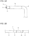
- Fig. 5A illustrates the electrical wire 10 composed of a single rod-like conductor 11.
- each one of the preliminary conductors 15 constituting the sub routes are connected to each other to form the rod-like conductor 11, and the rod-like conductor 11 including connections between each of the preliminary conductors 15 is covered by the insulation sheath 14 in the longitudinal direction.
- a method for connecting the preliminary conductors 15 of the rod-like conductor 11 is not limited to the ultrasonic bonding exemplified in the embodiment, but may be crimping, pressure bonding, or joining using an attachment. That is, the preliminary conductors 15 may be connected to each other by at least one of ultrasonic bonding, crimping, pressure welding, and joining using an attachment.
- the conductors 12 of the preliminary conductors 15 are connected to each other by joining using an attachment 17.
- the attachment 17 is a tubular member made of a conductive metallic material, and both ends of the attachment 17 are crimped to the ends of the conductors 12 of the preliminary conductors 15, respectively. As a result, the preliminary conductors 15 are electrically connected to each other through the attachment 17.
- a connecting material made of zinc is interposed between end sections of the conductors 12 of the preliminary conductors 15, and the end sections of the conductors 12 of the preliminary conductor 15 may be heated under this condition while being pressed in a face-to-face direction. In this way, the end sections of the preliminary conductors 15 are pressed against each other, integrated, and electrically connected by the connecting member.
- the conductor 12 of the rod-like conductor 11 may be made of a conductive metal material, or may be made of copper or a copper alloy, for example.
- the conductor 12 is made of aluminum, the electrical wire 10 can be considerably reduced in weight as compared with the case where the conductor 12 is made of copper.
Abstract
Description
- This application is based on and claims priority from Japanese Patent Application No.
2018-041023 filed on March 7, 2018 - One or more embodiments of the present invention relate to a method for manufacturing an electrical wire, and an electrical wire.
- A wire harness configured to insert a plurality of electrical wires into a hollow portion of a metal pipe as a bundle is known, in which the electrical wires connect between various components (battery, inverter, motor and the like) of an electrical drive system such as a hybrid automobile and an electric automobile (see, for example,
JP-A-2004-171952 - The wire harness of the related art described above includes a metal pipe formed in a shape corresponding to the wiring route so that the wires are easily arranged into the wiring route. However, such a wire harness requires that a long metal pipe for inserting the electrical wires therein be processed into a complicated shape corresponding to the wiring route, and such processing requires time and labor. Further, with such a wire harness, it is necessary to insert a plurality of electrical wires through the hollow portions of the metal pipe processed into a complicated shape, which also requires time and labor for the insertion work.
- One or more embodiments of the present invention have been made in consideration of the issues mentioned above, and accordingly, and is to provide a method capable of manufacturing an electrical wire with excellent wiring workability with ease, and an electrical wire with excellent wiring workability that can be manufactured with ease.
- In order to achieve the above-described object, a method for manufacturing an electrical wire according to one or more aspects of the present invention is summarized as the below-described (1) to (3).
- (1) A method for manufacturing an electrical wire, the electrical wire including a rod-like conductor having a shape corresponding to a predetermined wiring route and also having rigidity to enable the rod-like conductor to hold the shape by itself, and an insulation sheath covering the rod-like conductor, the method including:
- preparing a plurality of rod-like preliminary conductors having the rigidity so as to correspond to a plurality of sub routes into which the wiring route is divided;
- processing at least one of the plurality of preliminary conductors into a shape conforming to the corresponding sub routes;
- connecting the plurality of preliminary conductors to form the rod-like conductor; and
- forming the insulation sheath to cover the rod-like conductor.
- (2) The method for manufacturing an electrical wire according to (1),
wherein the electrical wire includes a plurality of the rod-like conductors having a shape corresponding to the wiring route, and
wherein when the insulation sheath is formed, the insulation sheath is formed to cover and bundle the plurality of rod-like conductors such that the plurality of rod-like conductors are integrated. - (3) The method for manufacturing an electrical wire according to (1) or (2),
wherein when the rod-like conductor is formed, the plurality of preliminary conductors are connected by at least one of ultrasonic bonding, crimping, pressure welding, and joining using an attachment. - According to a method for manufacturing the electrical wire having configuration (1) described above, at least one of a plurality of rod-like preliminary conductors is processed into a shape conforming to the corresponding sub route. Once processed, the preliminary conductor is capable of holding the processed shape by itself. These preliminary conductors are connected to form a rod-like conductor, and then an insulation sheath is formed to cover the rod-like conductor. Accordingly, it is possible to obtain the electrical wire, in which the rod-like conductor is covered with the insulation sheath, the conductor having a shape corresponding to a predetermined wiring route and also having rigidity that allows the rod-like conductor to hold shape by itself. With the electrical wire manufactured as described above, it is possible to easily manufacture the electrical wires with excellent wiring workability in the wiring route, compared to a wire harness (electrical wire) that is manufactured by processing the long pipe as described above into a predetermined shape and then inserting an electrical wire thereinto.
- Further, since at least one of the preliminary conductors corresponding to the plurality of sub routes is processed to correspond to the shape of the wiring route, and these preliminary conductors are connected to each other, it is possible to improve the workability of processing and contribute to facilitated manufacturing.
- "Rigidity" described above represents the force (load/deformation amount) necessary to cause a unit deformation of an object, and represents the degree of difficulty to deform the object. Rigidity includes bending rigidity, shear rigidity, torsional rigidity, and the like.
- According to a method for manufacturing the electrical wire having configuration (2) described above, it is possible to bundle and integrate a plurality of rod-like conductors with an insulation sheath. As a result, electrical wires that correspond to a plurality of circuits can be easily manufactured.
- According to the method for manufacturing the electrical wire having the configuration (3) described above, it is possible to easily manufacture the electrical wires including rod-like conductors shaped corresponding to the wiring route by easily connecting the preliminary conductors to each other with at least one of ultrasonic bonding, crimping, pressure welding, and joining using an attachment. Accordingly, electrical wires having a shape corresponding to the wiring route can be manufactured without requiring complicated processing.
- In order to achieve the above-described object, an electrical wire according to one or more aspects of the present invention is summarized as the below-described (4).
(4) An electrical wire including: - a rod-like conductor having a shape corresponding to a predetermined wiring route and also having rigidity to enable the rod-like conductor to hold the shape by itself; and
- an insulation sheath covering the rod-like conductor,
- wherein the rod-like conductor is formed by connecting a plurality of rod-like preliminary conductors with each other, the plurality of rod-like preliminary conductors having the rigidity and corresponding to a plurality of sub routes into which the wiring route is divided.
- According to the electrical wire having the configuration (4) described above, the wire can hold a shape corresponding to a predetermined wiring route by itself, and accordingly, it is possible to improve the wiring workability when wiring into the automobile body, or the like.
- According to one or more aspects of the present invention, it is possible to provide a method for manufacturing an electrical wire having excellent wiring workability with ease, and an electrical wire with excellent wiring workability that can be manufactured with ease.
- One or more aspects of the present invention have been briefly described above. Furthermore, the details will be further clarified by reading through the aspects for carrying out the invention (hereinafter referred to as "an embodiment") described below with reference to the accompanying drawings.
-
-
Fig. 1 is a schematic side view of an automobile in which electrical wires are wired, according to an embodiment; -
Figs. 2A and 2B are provided to explain a wiring route and a structure of the electrical wires according to the embodiment, in whichFig. 2A is an overall view of the electrical wires formed in a shape corresponding to the wiring route, andFig. 2B is a perspective view of a portion of the electrical wires; -
Figs 3A to 3C are provided to explain a method for manufacturing the electrical wires according to the embodiment, in whichFigs. 3A to 3C are perspective views of preliminary conductors in each step; -
Figs. 4A and 4B are provided to explain a covering process in a method for manufacturing an electrical wire, in whichFig. 4A is a perspective view of electrical wires before contraction of an insulation sheath, andFig. 4B is a perspective view of the electrical wire after contraction of the insulation sheath; and -
Figs. 5A and 5B are provided to explain a modified example of an electrical wire, in whichFig. 5A is a perspective view of a portion of a rod-like conductor, andFig. 5B is a perspective view of a connection between preliminary conductors constituting the rod-like conductor. - Hereinafter, a method for manufacturing an electrical wire and the electrical wire according to an embodiment of the present invention will be described with reference to the drawings.
-
Fig. 1 illustrates ahybrid automobile 20 with anelectrical wire 10 installed therein, according to an embodiment of the present invention. Hereinafter, thehybrid automobile 20 is also simply referred to as "automobile 20". - As illustrated in
Fig. 1 , theautomobile 20 includes abattery 22 disposed in a rear portion of anautomobile body 21, and apower control unit 23 disposed in a front portion of theautomobile body 21. Theautomobile 20 includes a generator motor (MG) and an internal combustion engine, both not illustrated. The generator motor generates power by the power supplied from the internal combustion engine. The generator motor is controlled by thepower control unit 23. - The
electrical wire 10 is connected to thebattery 22 and thepower control unit 23 by aconnector 24. Thebattery 22 and thepower control unit 23 are connected by theelectrical wire 10 so as to be capable of supplying and receiving electric power. - As illustrated in
Fig. 2A , theelectrical wire 10 has a shape corresponding to a predetermined wiring route to be wired into theautomobile body 21, and is wired into theautomobile body 21 in this shape. As illustrated inFig. 2B , theelectrical wire 10 includes a pair of rod-like conductors 11, and aninsulation sheath 14 covering the pair of rod-like conductors 11. The pair of rod-like conductors 11 are covered and bundled together to be integrated by theinsulation sheath 14. - For example, each of the rod-
like conductors 11 includes around bar conductor 12 made of aluminum or an aluminum alloy, with an outer circumference of theconductor 12 being covered with aninsulation sheath 13. The rod-like conductor 11 has a shape corresponding to the predetermined wiring route described above, and also has rigidity to allow the rod-like conductor 11 to hold the shape corresponding to the wiring route by itself. - As illustrated in
Fig. 2A , the wiring route of theelectrical wire 10 in theautomobile 20 is divided into a plurality of sub routes SR1 to SR9. The rod-like conductor 11 included in theelectrical wire 10 is composed of a plurality of rod-likepreliminary conductors 15 corresponding to the plurality of divided sub routes. In the present example, the rod-like conductor 11 is divided into sub routes SR1 to SR9 in order from one end side. Parts of thepreliminary conductor 15 are processed into shapes conforming to each of the corresponding sub routes SR1 to SR9. Specifically, thepreliminary conductors 15 of the sub routes SR1, SR3, SR5, SR7, and SR9 are formed as a straight line, and thepreliminary conductors 15 of the sub routes SR2, SR4, SR6 and SR8 are processed into shapes having bends B. - The respective
preliminary conductors 15 are connected to each other to form the rod-like conductor 11. Thepreliminary conductors 15 are connected by at least one of ultrasonic bonding, crimping, pressure welding, and joining using an attachment. Thus, thepreliminary conductors 15 are electrically connected to each other. Portions of theconductors 12 are exposed through theinsulation sheath 13 at the connections connecting thepreliminary conductors 15, and the exposedconductors 12 are connected to each other. Thepreliminary conductors 15 are covered substantially entirely in the longitudinal direction by theinsulation sheath 14, including the connections where theconductors 12 are exposed through theinsulation sheath 13 and connected to each other. - Next, a method for manufacturing the
electrical wire 10 having the configuration described above will be described. The following description will be given by exemplifying a certain part of the configuration that includes the sub route SR1 and the sub route SR2 of theelectrical wire 10. -
Figs. 3A to 3C are views for explaining each step of the method for manufacturing the electrical wire according to the embodiment.Figs. 4A and 4B are views for explaining covering step of the method for manufacturing the electrical wire. - The plurality of rod-like
preliminary conductors 15 are prepared to correspond to the plurality of sub routes SR1 to SR9 into which the wiring route is divided. For example, as illustrated inFig. 3A , a pair ofpreliminary conductors 15 corresponding to the sub routes SR1 and SR2 are prepared for each of the sub routes SR1 and SR2. The lengths of thepreliminary conductors 15 are adjusted to correspond to the respective sub routes SR1 and SR2. - Predetermined portions of the plurality of
preliminary conductors 15 are processed into shapes conforming to the sub routes SR1 to SR9. For example, as illustrated inFig. 3B , thepreliminary conductors 15 used for the sub route SR2 of the sub routes SR1 and SR2 are bent based on the shape of the sub route SR2 having the bend B. Theinsulation sheath 13 is removed from ends where thepreliminary conductors 15 of the sub routes SR1 and SR2 are connected to each other, to expose theconductors 12. - The plurality of
preliminary conductors 15 are connected to form the rod-like conductor 11. For example, as illustrated inFig. 3C , for the sub routes SR1 and SR2, the ends subjected to the terminal treatment of thepreliminary routes 15 of the sub routes SR1 and SR2 are connected to each other. Theconductors 12 of thepreliminary conductors 15 are bonded to each other by ultrasonic bonding, for example. As a result, thepreliminary conductors 15 of the sub routes SR1 and SR2 are electrically connected to each other. - The
insulation sheath 14 is formed to cover the rod-like conductor 11 including thepreliminary conductors 15. For example, for the sub routes SR1 and SR2, first, as illustrated inFig. 4A , theinsulation sheath 14 formed of a heat shrinkable resin is applied in a longitudinal direction on the pair of rod-like conductors 11 including the connections between thepreliminary conductors 15 of the sub routes SR1 and SR2. Here, when the length of theinsulation sheath 14 is shorter than the entire length of the rod-like conductor 11, as the overlappingportion 14a illustrated inFig. 4A , a plurality ofinsulation sheaths 14 are applied on the rod-shapedconductors 11, and the ends of theseinsulation sheaths 14 are overlapped with each other. Next, theinsulation sheaths 14 are heated to be shrunk. Thus, as illustrated inFig. 4B , the pair of rod-like conductors 11 are covered and bundled together to be integrated by theinsulation sheaths 14. Here, therespective insulation sheaths 14 are brought into close contact with each other without allowing any gaps at the overlappingportion 14a of the shrunkinsulation sheaths 14. Theinsulation sheaths 14 may be formed of an ultraviolet curable resin or may be formed by tape winding. - As the steps described above are performed, the
electrical wire 10 is obtained, in which a pair of rod-shapedconductors 11 having a shape corresponding to a predetermined wiring route and also having rigidity to allow the rod-like conductors 11 to hold the shape by themselves are covered and integrated with theinsulation sheath 14. - As described above, according to a method for manufacturing the electrical wire according to the embodiment, at least one of a plurality of rod-like
preliminary conductors 15 is processed into a shape conforming to the corresponding sub routes SR1 to SR9. Thepreliminary conductors 15 are connected to form a rod-like conductor 11, and then aninsulation sheath 14 is formed to cover the rod-like conductor 11. Accordingly, it is possible to obtain theelectrical wire 10, which is excellent in wiring workability, and in which the rod-like conductor 11 having a shape corresponding to a predetermined wiring route and also having rigidity that allows the rod-like conductor 11 to hold shape by itself is covered with theinsulation sheath 14. That is, it is possible to manufacture theelectrical wire 10 having excellent wiring workability in the wiring route with increased ease, compared to a wire harness in which a long metal pipe is processed into a shape corresponding to a wiring route and a wire is inserted through the metal pipe having the complicated shape. - It is possible to improve the workability of the processing and facilitate the manufacturing when compared with when at least one of the
preliminary conductors 15 corresponding to the plurality of sub routes SR1 to SR9 is processed and then the onepreliminary conductor 15 is processed according to the wiring route of a long rod-like conductor 11 to be connected. - In particular, since a plurality (in the present example, a pair) of rod-
like conductors 11 can be integrated by theinsulation sheath 14, theelectrical wires 10 that can correspond to a plurality of circuits can be easily manufactured. - The plurality of
preliminary conductors 15 are connected by at least one of ultrasonic bonding, crimping, pressure welding, and joining using an attachment. As a result, it is possible to easily manufacture theelectrical wire 10, which includes the rod-like conductor 11 that easily connects thepreliminary conductors 15 to each other and also has a shape corresponding to the wiring route. - For the
electrical wire 10 according to the embodiment, since theelectrical wire 10 has a shape corresponding to a predetermined wiring route and can hold the shape by itself, the wiring workability during wiring into theautomobile body 21 can be improved. - The present invention is not limited to the embodiment described above, and various modifications can be adopted within the scope of the present invention. For example, the present invention is not limited to the embodiment described above, but may encompass modifications or improvements, as appropriate. Materials, shapes, dimensions, numbers, positions, and the like of the constituent elements in the embodiment above described are not limited, but rather arbitrary as far as the present invention can be achieved.
- For example, the number of the rod-
like conductors 11 included in theelectrical wire 10 is not limited to a pair, but may be three or more, or may be one.Fig. 5A illustrates theelectrical wire 10 composed of a single rod-like conductor 11. In theelectrical wire 10, each one of thepreliminary conductors 15 constituting the sub routes are connected to each other to form the rod-like conductor 11, and the rod-like conductor 11 including connections between each of thepreliminary conductors 15 is covered by theinsulation sheath 14 in the longitudinal direction. - A method for connecting the
preliminary conductors 15 of the rod-like conductor 11 is not limited to the ultrasonic bonding exemplified in the embodiment, but may be crimping, pressure bonding, or joining using an attachment. That is, thepreliminary conductors 15 may be connected to each other by at least one of ultrasonic bonding, crimping, pressure welding, and joining using an attachment. InFig. 5B , theconductors 12 of thepreliminary conductors 15 are connected to each other by joining using anattachment 17. Theattachment 17 is a tubular member made of a conductive metallic material, and both ends of theattachment 17 are crimped to the ends of theconductors 12 of thepreliminary conductors 15, respectively. As a result, thepreliminary conductors 15 are electrically connected to each other through theattachment 17. - When connecting the
preliminary conductors 15 to each other by pressure welding, a connecting material made of zinc is interposed between end sections of theconductors 12 of thepreliminary conductors 15, and the end sections of theconductors 12 of thepreliminary conductor 15 may be heated under this condition while being pressed in a face-to-face direction. In this way, the end sections of thepreliminary conductors 15 are pressed against each other, integrated, and electrically connected by the connecting member. - While the embodiment is described above with exemplifying a case where the rod-
like conductor 11 made of aluminum or an aluminum alloy is used in theconductor 12, theconductor 12 of the rod-like conductor 11 may be made of a conductive metal material, or may be made of copper or a copper alloy, for example. When theconductor 12 is made of aluminum, theelectrical wire 10 can be considerably reduced in weight as compared with the case where theconductor 12 is made of copper. - Here, the features of a method for manufacturing an electrical wire and the electrical wire according to one or more embodiments of the present invention described above are summarized briefly as (1) to (4) below.
- (1) A method for manufacturing an electrical wire (10), the electrical wire (10) including a rod-like conductor (11) having a shape corresponding to a predetermined wiring route and also having rigidity to enable the rod-like conductor (11) to hold the shape by itself, and an insulation sheath (14) covering the rod-like conductor (11), the method including:
- preparing a plurality of rod-like preliminary conductors (15) having the rigidity so as to correspond to a plurality of sub routes (SRI to SR9) into which the wiring route is divided;
- processing at least one of the plurality of preliminary conductors (15) into a shape conforming to the corresponding sub routes (SRI to SR9);
- connecting the plurality of preliminary conductors (15) to form the rod-like conductor (11); and
- forming the insulation sheath (14) to cover the rod-like conductor (11).
- (2) The method for manufacturing an electrical wire (10) according to (1),
wherein the electrical wire (10) includes a plurality of the rod-like conductors (11) having a shape corresponding to the wiring route, and
wherein when the insulation sheath (14) is formed, the insulation sheath (14) is formed to cover and bundle the plurality of rod-like conductors (11) such that the plurality of rod-like conductors (11) are integrated. - (3) The method for manufacturing an electrical wire (10) according to (1) or (2),
wherein when the rod-like conductor (11) is formed, the plurality of preliminary conductors (15) are connected by at least one of ultrasonic bonding, crimping, pressure welding, and joining using an attachment (17). - (4) An electrical wire (10) including:
- a rod-like conductor (11) having a shape corresponding to a predetermined wiring route and also having rigidity to enable the rod-like conductor (11) to hold the shape by itself; and
- an insulation sheath (14) covering the rod-like conductor (11),
- wherein the rod-like conductor (11) is formed by connecting a plurality of rod-like preliminary conductors (15) with each other, the plurality of rod-like preliminary conductors (15) having the rigidity and corresponding to a plurality of sub routes (SRI to SR9) into which the wiring route is divided.
Claims (4)
- A method for manufacturing an electrical wire, the electrical wire comprising a rod-like conductor having a shape corresponding to a predetermined wiring route and also having rigidity to enable the rod-like conductor to hold the shape by itself, and an insulation sheath covering the rod-like conductor, the method comprising:preparing a plurality of rod-like preliminary conductors having the rigidity so as to correspond to a plurality of sub routes into which the wiring route is divided;processing at least one of the plurality of preliminary conductors into a shape conforming to the corresponding sub routes;connecting the plurality of preliminary conductors to form the rod-like conductor; andforming the insulation sheath to cover the rod-like conductor.
- The method for manufacturing an electrical wire according to claim 1,
wherein the electrical wire comprises a plurality of the rod-like conductors having a shape corresponding to the wiring route, and
wherein when the insulation sheath is formed, the insulation sheath is formed to cover and bundle the plurality of rod-like conductors such that the plurality of rod-like conductors are integrated. - The method for manufacturing an electrical wire according to claim 1 or 2,
wherein when the rod-like conductor is formed, the plurality of preliminary conductors are connected by at least one of ultrasonic bonding, crimping, pressure welding, and joining using an attachment. - An electrical wire comprising:a rod-like conductor having a shape corresponding to a predetermined wiring route and also having rigidity to enable the rod-like conductor to hold the shape by itself; andan insulation sheath covering the rod-like conductor,wherein the rod-like conductor is formed by connecting a plurality of rod-like preliminary conductors with each other, the plurality of rod-like preliminary conductors having the rigidity and corresponding to a plurality of sub routes into which the wiring route is divided.
Applications Claiming Priority (1)
| Application Number | Priority Date | Filing Date | Title |
|---|---|---|---|
| JP2018041023A JP7017440B2 (en) | 2018-03-07 | 2018-03-07 | Manufacturing method of electric wire and electric wire |
Publications (2)
| Publication Number | Publication Date |
|---|---|
| EP3536559A1 true EP3536559A1 (en) | 2019-09-11 |
| EP3536559B1 EP3536559B1 (en) | 2021-11-03 |
Family
ID=65657237
Family Applications (1)
| Application Number | Title | Priority Date | Filing Date |
|---|---|---|---|
| EP19159626.1A Active EP3536559B1 (en) | 2018-03-07 | 2019-02-27 | Method for manufacturing electrical wire |
Country Status (4)
| Country | Link |
|---|---|
| US (1) | US10916360B2 (en) |
| EP (1) | EP3536559B1 (en) |
| JP (1) | JP7017440B2 (en) |
| CN (1) | CN110247274B (en) |
Families Citing this family (4)
| Publication number | Priority date | Publication date | Assignee | Title |
|---|---|---|---|---|
| DE102018213518A1 (en) * | 2018-08-10 | 2020-02-13 | Bayerische Motoren Werke Aktiengesellschaft | Line arrangement, component arrangement and working device |
| US11211184B2 (en) * | 2019-01-23 | 2021-12-28 | Pratt & Whitney Canada Corp. | System of harness and engine case for aircraft engine |
| JP2023086276A (en) * | 2021-12-10 | 2023-06-22 | 株式会社オートネットワーク技術研究所 | Wire Harness |
| WO2023158758A1 (en) * | 2022-02-18 | 2023-08-24 | Tesla, Inc. | Multicore rigid busbar for electric power distribution |
Citations (5)
| Publication number | Priority date | Publication date | Assignee | Title |
|---|---|---|---|---|
| JP2004171952A (en) | 2002-11-20 | 2004-06-17 | Auto Network Gijutsu Kenkyusho:Kk | Conductive line provided with shield function |
| DE102006050705A1 (en) * | 2006-10-24 | 2008-04-30 | Auto Kabel Managementgesellschaft Mbh | Battery line for a vehicle comprises a flat conductor formed as one piece between a first connecting element and a second connecting element and has parts connected together along the conductor |
| DE102006062795B4 (en) * | 2006-10-02 | 2010-10-21 | Lisa Dräxlmaier GmbH | High current cable e.g. battery cable, for vehicle i.e. motor vehicle, has separated individual rails, which are electrically connected with one another, where rails have same or different cross-sectional areas and flat cross section |
| US20160129861A1 (en) * | 2013-07-19 | 2016-05-12 | Yazaki Corporation | Wire Harness |
| US20160152197A1 (en) * | 2014-11-27 | 2016-06-02 | Yazaki Corporation | Wire harness |
Family Cites Families (4)
| Publication number | Priority date | Publication date | Assignee | Title |
|---|---|---|---|---|
| US5530625A (en) * | 1994-09-07 | 1996-06-25 | Electro-Wire Products, Inc. | Electrical interface board including flat ribbon conductors positioned on edge |
| JP5643080B2 (en) * | 2010-12-28 | 2014-12-17 | 矢崎総業株式会社 | Wire harness and method of manufacturing wire harness |
| JP6610392B2 (en) | 2016-04-07 | 2019-11-27 | 住友電装株式会社 | Conductor connection structure and wire harness |
| JP7382721B2 (en) | 2018-02-09 | 2023-11-17 | 古河電気工業株式会社 | Connection structure for flat electric wires and wire harness including the connection structure |
-
2018
- 2018-03-07 JP JP2018041023A patent/JP7017440B2/en active Active
-
2019
- 2019-02-27 EP EP19159626.1A patent/EP3536559B1/en active Active
- 2019-03-05 US US16/292,971 patent/US10916360B2/en active Active
- 2019-03-06 CN CN201910167971.8A patent/CN110247274B/en active Active
Patent Citations (5)
| Publication number | Priority date | Publication date | Assignee | Title |
|---|---|---|---|---|
| JP2004171952A (en) | 2002-11-20 | 2004-06-17 | Auto Network Gijutsu Kenkyusho:Kk | Conductive line provided with shield function |
| DE102006062795B4 (en) * | 2006-10-02 | 2010-10-21 | Lisa Dräxlmaier GmbH | High current cable e.g. battery cable, for vehicle i.e. motor vehicle, has separated individual rails, which are electrically connected with one another, where rails have same or different cross-sectional areas and flat cross section |
| DE102006050705A1 (en) * | 2006-10-24 | 2008-04-30 | Auto Kabel Managementgesellschaft Mbh | Battery line for a vehicle comprises a flat conductor formed as one piece between a first connecting element and a second connecting element and has parts connected together along the conductor |
| US20160129861A1 (en) * | 2013-07-19 | 2016-05-12 | Yazaki Corporation | Wire Harness |
| US20160152197A1 (en) * | 2014-11-27 | 2016-06-02 | Yazaki Corporation | Wire harness |
Also Published As
| Publication number | Publication date |
|---|---|
| JP2019160421A (en) | 2019-09-19 |
| EP3536559B1 (en) | 2021-11-03 |
| US10916360B2 (en) | 2021-02-09 |
| CN110247274B (en) | 2021-05-25 |
| CN110247274A (en) | 2019-09-17 |
| US20190279790A1 (en) | 2019-09-12 |
| JP7017440B2 (en) | 2022-02-08 |
Similar Documents
| Publication | Publication Date | Title |
|---|---|---|
| EP3536559B1 (en) | Method for manufacturing electrical wire | |
| CN110199361B (en) | Wire harness | |
| US9666955B2 (en) | Conductive line and routing structure for the same | |
| US20090229880A1 (en) | Conductor and Wire Harness | |
| CN102055122A (en) | Wire harness | |
| CN110011078B (en) | Terminal-equipped electric wire and method for manufacturing terminal-equipped electric wire | |
| US9793625B2 (en) | Electric wire with connecting terminal and method for manufacturing such electric wire | |
| JP6813630B2 (en) | Wiring assembly for equipment | |
| CN108885924B (en) | Wire harness | |
| CN110021867A (en) | Multicore cable manufacturing device and multicore cable manufacturing method | |
| JP6708353B2 (en) | Shield terminal processing method and wire harness | |
| US11142145B2 (en) | Wire harness for regulating a routing path | |
| US10826201B2 (en) | Conductive member | |
| JP6719873B2 (en) | Wiring assembly for vehicle equipment | |
| JP5402599B2 (en) | Flat cable with terminal bracket and terminal crimping die for flat cable | |
| JP6593644B2 (en) | Wire connection structure and wire harness | |
| JP5365100B2 (en) | Wire harness including short circuit and method for manufacturing the same | |
| JP2018101578A (en) | Electric wire | |
| JP2021108534A (en) | Wiring assembly for devices | |
| JP5365099B2 (en) | Wire harness including short circuit | |
| JP2022086674A (en) | Wire with terminal and manufacturing method for the same | |
| EP3312936B1 (en) | Power terminal with crimping wings and a weld area | |
| WO2020080077A1 (en) | Connection structure for plurality of electrical wires | |
| JP2023023525A (en) | conductor wire | |
| CN114765312A (en) | Terminal-equipped electric wire and wire harness member provided with same |
Legal Events
| Date | Code | Title | Description |
|---|---|---|---|
| PUAI | Public reference made under article 153(3) epc to a published international application that has entered the european phase |
Free format text: ORIGINAL CODE: 0009012 |
|
| STAA | Information on the status of an ep patent application or granted ep patent |
Free format text: STATUS: REQUEST FOR EXAMINATION WAS MADE |
|
| 17P | Request for examination filed |
Effective date: 20190227 |
|
| AK | Designated contracting states |
Kind code of ref document: A1 Designated state(s): AL AT BE BG CH CY CZ DE DK EE ES FI FR GB GR HR HU IE IS IT LI LT LU LV MC MK MT NL NO PL PT RO RS SE SI SK SM TR |
|
| AX | Request for extension of the european patent |
Extension state: BA ME |
|
| GRAP | Despatch of communication of intention to grant a patent |
Free format text: ORIGINAL CODE: EPIDOSNIGR1 |
|
| STAA | Information on the status of an ep patent application or granted ep patent |
Free format text: STATUS: GRANT OF PATENT IS INTENDED |
|
| INTG | Intention to grant announced |
Effective date: 20210819 |
|
| GRAS | Grant fee paid |
Free format text: ORIGINAL CODE: EPIDOSNIGR3 |
|
| GRAA | (expected) grant |
Free format text: ORIGINAL CODE: 0009210 |
|
| STAA | Information on the status of an ep patent application or granted ep patent |
Free format text: STATUS: THE PATENT HAS BEEN GRANTED |
|
| AK | Designated contracting states |
Kind code of ref document: B1 Designated state(s): AL AT BE BG CH CY CZ DE DK EE ES FI FR GB GR HR HU IE IS IT LI LT LU LV MC MK MT NL NO PL PT RO RS SE SI SK SM TR |
|
| REG | Reference to a national code |
Ref country code: GB Ref legal event code: FG4D |
|
| REG | Reference to a national code |
Ref country code: AT Ref legal event code: REF Ref document number: 1443683 Country of ref document: AT Kind code of ref document: T Effective date: 20211115 Ref country code: CH Ref legal event code: EP |
|
| REG | Reference to a national code |
Ref country code: DE Ref legal event code: R096 Ref document number: 602019008803 Country of ref document: DE |
|
| REG | Reference to a national code |
Ref country code: IE Ref legal event code: FG4D |
|
| REG | Reference to a national code |
Ref country code: LT Ref legal event code: MG9D |
|
| REG | Reference to a national code |
Ref country code: NL Ref legal event code: MP Effective date: 20211103 |
|
| REG | Reference to a national code |
Ref country code: AT Ref legal event code: MK05 Ref document number: 1443683 Country of ref document: AT Kind code of ref document: T Effective date: 20211103 |
|
| PG25 | Lapsed in a contracting state [announced via postgrant information from national office to epo] |
Ref country code: RS Free format text: LAPSE BECAUSE OF FAILURE TO SUBMIT A TRANSLATION OF THE DESCRIPTION OR TO PAY THE FEE WITHIN THE PRESCRIBED TIME-LIMIT Effective date: 20211103 Ref country code: LT Free format text: LAPSE BECAUSE OF FAILURE TO SUBMIT A TRANSLATION OF THE DESCRIPTION OR TO PAY THE FEE WITHIN THE PRESCRIBED TIME-LIMIT Effective date: 20211103 Ref country code: FI Free format text: LAPSE BECAUSE OF FAILURE TO SUBMIT A TRANSLATION OF THE DESCRIPTION OR TO PAY THE FEE WITHIN THE PRESCRIBED TIME-LIMIT Effective date: 20211103 Ref country code: BG Free format text: LAPSE BECAUSE OF FAILURE TO SUBMIT A TRANSLATION OF THE DESCRIPTION OR TO PAY THE FEE WITHIN THE PRESCRIBED TIME-LIMIT Effective date: 20220203 Ref country code: AT Free format text: LAPSE BECAUSE OF FAILURE TO SUBMIT A TRANSLATION OF THE DESCRIPTION OR TO PAY THE FEE WITHIN THE PRESCRIBED TIME-LIMIT Effective date: 20211103 |
|
| PG25 | Lapsed in a contracting state [announced via postgrant information from national office to epo] |
Ref country code: IS Free format text: LAPSE BECAUSE OF FAILURE TO SUBMIT A TRANSLATION OF THE DESCRIPTION OR TO PAY THE FEE WITHIN THE PRESCRIBED TIME-LIMIT Effective date: 20220303 Ref country code: SE Free format text: LAPSE BECAUSE OF FAILURE TO SUBMIT A TRANSLATION OF THE DESCRIPTION OR TO PAY THE FEE WITHIN THE PRESCRIBED TIME-LIMIT Effective date: 20211103 Ref country code: PT Free format text: LAPSE BECAUSE OF FAILURE TO SUBMIT A TRANSLATION OF THE DESCRIPTION OR TO PAY THE FEE WITHIN THE PRESCRIBED TIME-LIMIT Effective date: 20220303 Ref country code: PL Free format text: LAPSE BECAUSE OF FAILURE TO SUBMIT A TRANSLATION OF THE DESCRIPTION OR TO PAY THE FEE WITHIN THE PRESCRIBED TIME-LIMIT Effective date: 20211103 Ref country code: NO Free format text: LAPSE BECAUSE OF FAILURE TO SUBMIT A TRANSLATION OF THE DESCRIPTION OR TO PAY THE FEE WITHIN THE PRESCRIBED TIME-LIMIT Effective date: 20220203 Ref country code: NL Free format text: LAPSE BECAUSE OF FAILURE TO SUBMIT A TRANSLATION OF THE DESCRIPTION OR TO PAY THE FEE WITHIN THE PRESCRIBED TIME-LIMIT Effective date: 20211103 Ref country code: LV Free format text: LAPSE BECAUSE OF FAILURE TO SUBMIT A TRANSLATION OF THE DESCRIPTION OR TO PAY THE FEE WITHIN THE PRESCRIBED TIME-LIMIT Effective date: 20211103 Ref country code: HR Free format text: LAPSE BECAUSE OF FAILURE TO SUBMIT A TRANSLATION OF THE DESCRIPTION OR TO PAY THE FEE WITHIN THE PRESCRIBED TIME-LIMIT Effective date: 20211103 Ref country code: GR Free format text: LAPSE BECAUSE OF FAILURE TO SUBMIT A TRANSLATION OF THE DESCRIPTION OR TO PAY THE FEE WITHIN THE PRESCRIBED TIME-LIMIT Effective date: 20220204 Ref country code: ES Free format text: LAPSE BECAUSE OF FAILURE TO SUBMIT A TRANSLATION OF THE DESCRIPTION OR TO PAY THE FEE WITHIN THE PRESCRIBED TIME-LIMIT Effective date: 20211103 |
|
| PG25 | Lapsed in a contracting state [announced via postgrant information from national office to epo] |
Ref country code: SM Free format text: LAPSE BECAUSE OF FAILURE TO SUBMIT A TRANSLATION OF THE DESCRIPTION OR TO PAY THE FEE WITHIN THE PRESCRIBED TIME-LIMIT Effective date: 20211103 Ref country code: SK Free format text: LAPSE BECAUSE OF FAILURE TO SUBMIT A TRANSLATION OF THE DESCRIPTION OR TO PAY THE FEE WITHIN THE PRESCRIBED TIME-LIMIT Effective date: 20211103 Ref country code: RO Free format text: LAPSE BECAUSE OF FAILURE TO SUBMIT A TRANSLATION OF THE DESCRIPTION OR TO PAY THE FEE WITHIN THE PRESCRIBED TIME-LIMIT Effective date: 20211103 Ref country code: EE Free format text: LAPSE BECAUSE OF FAILURE TO SUBMIT A TRANSLATION OF THE DESCRIPTION OR TO PAY THE FEE WITHIN THE PRESCRIBED TIME-LIMIT Effective date: 20211103 Ref country code: DK Free format text: LAPSE BECAUSE OF FAILURE TO SUBMIT A TRANSLATION OF THE DESCRIPTION OR TO PAY THE FEE WITHIN THE PRESCRIBED TIME-LIMIT Effective date: 20211103 Ref country code: CZ Free format text: LAPSE BECAUSE OF FAILURE TO SUBMIT A TRANSLATION OF THE DESCRIPTION OR TO PAY THE FEE WITHIN THE PRESCRIBED TIME-LIMIT Effective date: 20211103 |
|
| REG | Reference to a national code |
Ref country code: DE Ref legal event code: R097 Ref document number: 602019008803 Country of ref document: DE |
|
| PLBE | No opposition filed within time limit |
Free format text: ORIGINAL CODE: 0009261 |
|
| STAA | Information on the status of an ep patent application or granted ep patent |
Free format text: STATUS: NO OPPOSITION FILED WITHIN TIME LIMIT |
|
| PG25 | Lapsed in a contracting state [announced via postgrant information from national office to epo] |
Ref country code: MC Free format text: LAPSE BECAUSE OF FAILURE TO SUBMIT A TRANSLATION OF THE DESCRIPTION OR TO PAY THE FEE WITHIN THE PRESCRIBED TIME-LIMIT Effective date: 20211103 |
|
| 26N | No opposition filed |
Effective date: 20220804 |
|
| REG | Reference to a national code |
Ref country code: CH Ref legal event code: PL |
|
| REG | Reference to a national code |
Ref country code: BE Ref legal event code: MM Effective date: 20220228 |
|
| PG25 | Lapsed in a contracting state [announced via postgrant information from national office to epo] |
Ref country code: LU Free format text: LAPSE BECAUSE OF NON-PAYMENT OF DUE FEES Effective date: 20220227 Ref country code: AL Free format text: LAPSE BECAUSE OF FAILURE TO SUBMIT A TRANSLATION OF THE DESCRIPTION OR TO PAY THE FEE WITHIN THE PRESCRIBED TIME-LIMIT Effective date: 20211103 |
|
| PG25 | Lapsed in a contracting state [announced via postgrant information from national office to epo] |
Ref country code: SI Free format text: LAPSE BECAUSE OF FAILURE TO SUBMIT A TRANSLATION OF THE DESCRIPTION OR TO PAY THE FEE WITHIN THE PRESCRIBED TIME-LIMIT Effective date: 20211103 |
|
| PG25 | Lapsed in a contracting state [announced via postgrant information from national office to epo] |
Ref country code: FR Free format text: LAPSE BECAUSE OF NON-PAYMENT OF DUE FEES Effective date: 20220228 |
|
| PG25 | Lapsed in a contracting state [announced via postgrant information from national office to epo] |
Ref country code: LI Free format text: LAPSE BECAUSE OF NON-PAYMENT OF DUE FEES Effective date: 20220228 Ref country code: IE Free format text: LAPSE BECAUSE OF NON-PAYMENT OF DUE FEES Effective date: 20220227 Ref country code: CH Free format text: LAPSE BECAUSE OF NON-PAYMENT OF DUE FEES Effective date: 20220228 |
|
| PG25 | Lapsed in a contracting state [announced via postgrant information from national office to epo] |
Ref country code: BE Free format text: LAPSE BECAUSE OF NON-PAYMENT OF DUE FEES Effective date: 20220228 |
|
| PG25 | Lapsed in a contracting state [announced via postgrant information from national office to epo] |
Ref country code: IT Free format text: LAPSE BECAUSE OF FAILURE TO SUBMIT A TRANSLATION OF THE DESCRIPTION OR TO PAY THE FEE WITHIN THE PRESCRIBED TIME-LIMIT Effective date: 20211103 |
|
| PGFP | Annual fee paid to national office [announced via postgrant information from national office to epo] |
Ref country code: DE Payment date: 20221230 Year of fee payment: 5 |
|
| GBPC | Gb: european patent ceased through non-payment of renewal fee |
Effective date: 20230227 |
|
| PG25 | Lapsed in a contracting state [announced via postgrant information from national office to epo] |
Ref country code: GB Free format text: LAPSE BECAUSE OF NON-PAYMENT OF DUE FEES Effective date: 20230227 |
|
| PG25 | Lapsed in a contracting state [announced via postgrant information from national office to epo] |
Ref country code: GB Free format text: LAPSE BECAUSE OF NON-PAYMENT OF DUE FEES Effective date: 20230227 |
|
| PG25 | Lapsed in a contracting state [announced via postgrant information from national office to epo] |
Ref country code: MK Free format text: LAPSE BECAUSE OF FAILURE TO SUBMIT A TRANSLATION OF THE DESCRIPTION OR TO PAY THE FEE WITHIN THE PRESCRIBED TIME-LIMIT Effective date: 20211103 Ref country code: CY Free format text: LAPSE BECAUSE OF FAILURE TO SUBMIT A TRANSLATION OF THE DESCRIPTION OR TO PAY THE FEE WITHIN THE PRESCRIBED TIME-LIMIT Effective date: 20211103 |
|
| PGFP | Annual fee paid to national office [announced via postgrant information from national office to epo] |
Ref country code: DE Payment date: 20231229 Year of fee payment: 6 |