EP3536435A1 - Method for welding zinc-coated high-strength steel resistance spot having good joint properties - Google Patents
Method for welding zinc-coated high-strength steel resistance spot having good joint properties Download PDFInfo
- Publication number
- EP3536435A1 EP3536435A1 EP17868072.4A EP17868072A EP3536435A1 EP 3536435 A1 EP3536435 A1 EP 3536435A1 EP 17868072 A EP17868072 A EP 17868072A EP 3536435 A1 EP3536435 A1 EP 3536435A1
- Authority
- EP
- European Patent Office
- Prior art keywords
- welding
- pulse
- time
- current
- welding pulse
- Prior art date
- Legal status (The legal status is an assumption and is not a legal conclusion. Google has not performed a legal analysis and makes no representation as to the accuracy of the status listed.)
- Granted
Links
Images

Classifications
-
- B—PERFORMING OPERATIONS; TRANSPORTING
- B23—MACHINE TOOLS; METAL-WORKING NOT OTHERWISE PROVIDED FOR
- B23K—SOLDERING OR UNSOLDERING; WELDING; CLADDING OR PLATING BY SOLDERING OR WELDING; CUTTING BY APPLYING HEAT LOCALLY, e.g. FLAME CUTTING; WORKING BY LASER BEAM
- B23K11/00—Resistance welding; Severing by resistance heating
- B23K11/10—Spot welding; Stitch welding
- B23K11/11—Spot welding
-
- B—PERFORMING OPERATIONS; TRANSPORTING
- B23—MACHINE TOOLS; METAL-WORKING NOT OTHERWISE PROVIDED FOR
- B23K—SOLDERING OR UNSOLDERING; WELDING; CLADDING OR PLATING BY SOLDERING OR WELDING; CUTTING BY APPLYING HEAT LOCALLY, e.g. FLAME CUTTING; WORKING BY LASER BEAM
- B23K11/00—Resistance welding; Severing by resistance heating
- B23K11/10—Spot welding; Stitch welding
- B23K11/11—Spot welding
- B23K11/115—Spot welding by means of two electrodes placed opposite one another on both sides of the welded parts
-
- B—PERFORMING OPERATIONS; TRANSPORTING
- B23—MACHINE TOOLS; METAL-WORKING NOT OTHERWISE PROVIDED FOR
- B23K—SOLDERING OR UNSOLDERING; WELDING; CLADDING OR PLATING BY SOLDERING OR WELDING; CUTTING BY APPLYING HEAT LOCALLY, e.g. FLAME CUTTING; WORKING BY LASER BEAM
- B23K11/00—Resistance welding; Severing by resistance heating
- B23K11/24—Electric supply or control circuits therefor
- B23K11/241—Electric supplies
Definitions
- the invention relates to a welding method of auto steel sheet, and in particular to a resistance spot welding method of galvanized steel sheets with tensile strength no less than 590 Mpa.
- CN102489859A nugget metal grains are refined by using a method with inoculant alloy paste, so that the tissues of the joints are improved to improve the mechanical property of a joint in welding spot of the advanced high-strength steel
- "A resistance-laser hybrid spot welding method for High-strength steel" CN102500936A: the performance of a joint of the high-strength steel is improved by means of a composite connection mode of a laser welding and a spot welding.
- the purpose of the present invention is to provide a resistance spot welding method of galvanized high-strength steel with good joint performance, which can improve the plasticity of joint and increase the probability of button pullout failure of the welding spot during detection of the fracture while suppressing the generation of liquid metal embrittlement (LME) cracks during the spot welding of high-strength steel galvanized plates.
- LME liquid metal embrittlement
- a resistance spot welding method of galvanized high-strength steel with good joint performance three welding pulses are used within one spot welding schedule; the first welding pulse and the second welding pulse are used for generating a nugget and suppressing the generation of liquid metal embrittlement (LME) cracks, wherein the first welding pulse generates a nugget having a diameter of 3.75T 1/2 -4.25T 1/2 , and T represents a plate thickness; the second welding pulse causes the nugget to grow slowly; and a third welding pulse is a tempering pulse, which is used for improving the plasticity of a welding spot.
- LME liquid metal embrittlement
- a time t1 of the first welding pulse is set and a welding current I1 of the first welding pulse is obtained through tests, and the welding current I1 of the first welding pulse is a welding current upon generating the nugget having the diameter of 3.75T 1/2 -4.25T 1/2 ; and a welding current 12 and a time t2 of the second welding pulse and a welding current I3 and a time t3 of the third welding pulse are calculated by the welding current I1 and the time t1 of the first welding pulse.
- the LME cracks during the spot welding of high-strength steel galvanized plates can be effectively suppressed, and the plasticity of the welding point can also be improved.
- the resistance spot welding method of the present invention three welding pulses are used within one spot welding schedule, the first and second pulses are used for generating the nugget and suppressing the generation of the LME cracks, and the third welding pulse is the tempering pulse, which is used for improving the plasticity of the welding point, so that the fracture mode of the welding spot during the broken testing is improved.
- the spot welding method provided by the present invention clarifies a setting method of the welding currents I and the times t in the three welding pulses and a mathematical relationship therebetween, and the welding current 12 and the time t2 of the second welding pulse and the welding current I3 and the time t3 of the third welding pulse can be conveniently calculated by the welding current I1 and the time t1 of the first welding pulse obtained through a few tests, so that a spot welding process, which can not only suppress the LME cracks during the spot welding of the high-strength steel galvanized plates, but also can improve the plasticity of the welding point, is implemented.
- the liquid metal embrittlement (LME) cracks during the spot welding of the high-strength steel galvanized plates can be effectively suppressed, meanwhile, the plasticity of the welding point is improved, and the probability of button pullout failure of the welding point during broken testing is increased. Therefore, the joint by spot welding of the high-strength steel galvanized plates with more reliable quality and more excellent performance is obtained, and a useful guidance can be provided for the welding production of the high-strength steel galvanized plates.
- the present invention discloses a resistance spot welding method of galvanized steel plates with a tensile strength no less than 590Mpa.
- the plasticity of welding spot can be improved, and the probability of button pullout failure of the welding spots during broken testing can be increased while the generation of liquid metal embrittlement (LME) cracks during the spot welding of high-strength steel galvanized plates are suppressed.
- LME liquid metal embrittlement
- a resistance spot welding method of galvanized high-strength steel with good joint performance three welding pulses are used within one spot welding schedule; a first welding pulse and a second welding pulse are used for generating a nugget and suppressing the generation of LME cracks, wherein the first welding pulse generates a nugget having a diameter of 3.75T 1/2 -4.25T 1/2 , and T represents a plate thickness; the second welding pulse causes the nugget to grow slowly; and a third welding pulse is a tempering pulse, which is used for improving the plasticity of a welding spot.
- a welding current 12 and a time t2 of the second welding pulse and a welding current I3 and a time t3 of the third welding pulse are calculated by the welding current I1 and the time t1 of the first welding pulse.
- the welding current 12 and the time t2 of the second welding pulse and the welding current I3 and the time t3 of the third welding pulse can be conveniently calculated by the welding current I1 and the time t1 of the first welding pulse obtained through a few tests, so that the spot welding process, which can not only suppress the LME cracks during the spot welding of the high-strength steel galvanized plates, but also can improve the plasticity of the welding spot, is implemented.
- the working principle of the resistance spot welding method of galvanized high-strength steel with good joint performance of the present invention is as follows: A stress and a suitable temperature range (the range of the galvanized high-strength steel is 700 °C to 950 °C) are two necessary conditions for the generation of the LME cracks.
- the galvanized high-strength steel has the above two conditions in a spot welding process, and thus generates the LME cracks.
- the design idea of the present invention is to avoid the occurrence of the LME cracks by reducing the stress level of a spot welding LME crack sensitive region X, as shown in Fig.3 .
- the specific principle is as follows: with the increase of heat input during the spot welding, a diameter D and a height h of the nugget Y increase continuously. Since the high-strength steel, especially ultra-high-strength steel, has the addition of more alloy elements to a base material, it has high electrical resistivity, the heat generation speed during the spot welding is high, and the nugget grows at a high speed.
- the height h of the nugget grows too fast, so that the thickness T' of the unmelted base material in a plate thickness direction is rapidly decreased, and the size of the thickness T' of the unmelted base material directly affects the cross-sectional area under a load. Therefore, the smaller the thickness T' of the unmelted base material is, the greater the stress is.
- T the plate thickness
- the nugget is relatively small, the thickness T' of the unmelted base material is relatively large, and no LME crack of spot welding is generated.
- the second welding pulse with a short time t2 is applied to slowly grow the nugget, thus reducing the decrease speed of the thickness T' of the unmelted base material so as to reduce the stress level of the LME crack sensitive region and avoid the occurrence of the LME cracks.
- the pulse is the tempering pulse, which can effectively reduce the cooling speed of the region of the nugget and reduce the generation of a hardened structure of the joint, thereby improving the plasticity of the joint.
- the time of C1, C2 and HT (holding time) in Fig.2 is set according to Table 1.
- the interval time between the first welding pulse and the second welding pulse is C1, that is, a first cooling time C1
- the interval time between the second welding pulse and the third welding pulse is C2, that is, a second cooling time C2
- the holding time HT is a time after the third welding pulse
- their values for steel plates with different thicknesses are respectively set as follows: Table 1 Plate thickness/mm C1 C2 HT 0.9-1.2 1cyc 8cyc 5cyc 1.3-1.6 10cyc 1.7-2.0 12cyc
- Spot welding is performed on 1.6 mm hot-diped high-strength steel (the mechanical property and compositions are shown in table 2) by using three spot welding schedules No. 1, No. 2 and No. 3.
- the LME crack generations and the fracture modes of the welding spot during the broken testing are compared and evaluated.
- the characteristics and test results of the three spot welding schedules are shown in the Table 3.
- Table 2 Compositions and mechanical property of galvanized high-strength steel Plate thickness Mechanical property Chemical composition % Yield strength Tensile strength Elongation at fracture C Si Mn P S 1.6 mm 715 Mpa 1020 Mpa 20% 0.2 1.5 1.8 0.01 0.002
- Fig. 5 is a typical metallograph thereof.
- the spot welding process No.2 is as follows: Table 5 Spot welding process No.2 Plate thickness Diameter of end surface of electrode Welding pressure First pulse First cooling time Second pulse Second cooling time Third pulse Holding time Flow rate of cooling water Time Current Time Current Time Current 1.6mm 8mm 5.5kN 15 eye 8.0kA lcyc 4cyc 8.8-14.4kA 0 0 0 5cyc 2L/min
- the fracture mode of the welding spot is mainly interfacial fracture.
- TSS tensile-shear strength
- CTS cross tensile strength
- the spot welding process No.3 is as follows: Table 6 Spot welding process No.3 Plate thickness Diameter of end surface of electrode Welding pressure First pulse First cooling time Second pulse Second cooling time Third pulse Holding time Flow rate of cooling water Time Current Time Current Time Current 1.6mm 8mm 5.5kN 15 cyc 8.0kA 1cyc 4cyc 8.8-14.4 kA 10cyc 5cyc 5.3kA 5cyc 2L/min
- liquid metal embrittlement (LME) crack is not found in the entire welded region through the metallographic.
- the typical metallograph thereof is as shown in Fig.6 .
- the tensile-shear strength (TSS) and corss tensile strength (CTS) of the welding spot meet the requirements
- the fracture mode detected after the CTS test is all button pullout failure
- the ratio of button pullout failure at the welding spot detected after the TSS detection is also above 70%, which is much better than the result when the slow cooling pulse is not applied.
Landscapes
- Engineering & Computer Science (AREA)
- Mechanical Engineering (AREA)
- Resistance Welding (AREA)
Abstract
Description
- The invention relates to a welding method of auto steel sheet, and in particular to a resistance spot welding method of galvanized steel sheets with tensile strength no less than 590 Mpa.
- In recent years, as the oil price soars and people's awareness on energy conservation, environmental protection and safety of the whole vehicle continuously enhances, various weight-lighting technologies of a vehicle body have been widely used in the automobile manufacturing industry. On this basis, the utilization ratio of high-strength steel on the vehicle body is higher and higher. Resistance spot welding has been widely used in the automotive industry due to the advantages of high production efficiency and easy automation implementation and the like, and will continue to be the main welding method of high-strength steel plates in the automotive industry. Therefore, resistance spot welding technology of high-strength steel is widely focused.
- The joint of high-strength steel galvanized plates tends to occur following two problems during spot welding:
- 1. The joint occurs liquid metal embrittlement cracks, referred to LME cracks.
- 2. The joint tends to occur full interfacial fracture.
- With respect to the problem on the LME cracks, no relevant patent is applied after searching in domestic. Since the problem is a research hotspot in the industry in past two years, research literatures on its influencing factors and sensitivities have been published now and then. In a Document named "liquid metal embrittlement-free welds of Zn-coated twinning induced plasticity steels" by Rouholah Ashiri et al. published on the Scripta Materialia (Scripta Materialia 114 (2016) 41-47), a spot welding solution with two weld pulses adopted for 1.2mm hot-dip galvanized TWIP steel can effectively suppress generation of LME cracks in the spot welding. The process is shown in
Fig.1 . The first pulse is used for generating a nugget having a basic size, and the second pulse is used for slowly growing the nugget to reduce a residual stress. - In view of the brittleness of the welding spot of high-strength steel, a solution with tempering pulse during the welding process is generally used in the industry to improve the plasticity of the welding spot and to improve fracture mode of the welding spot during fracture testing. A specific setting mode of the tempering pulse is generally obtained through physical tests by an orthogonal method. A result of relevant patent search is as follows: "A method for improving mechanical property of a joint in welding spot of advanced high-strength steel" (Patent No.
CN102489859A ): nugget metal grains are refined by using a method with inoculant alloy paste, so that the tissues of the joints are improved to improve the mechanical property of a joint in welding spot of the advanced high-strength steel; "A resistance-laser hybrid spot welding method for High-strength steel" (CN102500936A ): the performance of a joint of the high-strength steel is improved by means of a composite connection mode of a laser welding and a spot welding. - The purpose of the present invention is to provide a resistance spot welding method of galvanized high-strength steel with good joint performance, which can improve the plasticity of joint and increase the probability of button pullout failure of the welding spot during detection of the fracture while suppressing the generation of liquid metal embrittlement (LME) cracks during the spot welding of high-strength steel galvanized plates.
- In order to achieve the above technical purpose, the present invention adopts the following technical solution:
A resistance spot welding method of galvanized high-strength steel with good joint performance, three welding pulses are used within one spot welding schedule; the first welding pulse and the second welding pulse are used for generating a nugget and suppressing the generation of liquid metal embrittlement (LME) cracks, wherein the first welding pulse generates a nugget having a diameter of 3.75T1/2-4.25T1/2, and T represents a plate thickness; the second welding pulse causes the nugget to grow slowly; and a third welding pulse is a tempering pulse, which is used for improving the plasticity of a welding spot. - A time t1 of the first welding pulse is set and a welding current I1 of the first welding pulse is obtained through tests, and the welding current I1 of the first welding pulse is a welding current upon generating the nugget having the diameter of 3.75T1/2-4.25T1/2; and a
welding current 12 and a time t2 of the second welding pulse and a welding current I3 and a time t3 of the third welding pulse are calculated by the welding current I1 and the time t1 of the first welding pulse. - By the resistance spot welding method of galvanized high-strength steel with good joint performance of the present invention, the LME cracks during the spot welding of high-strength steel galvanized plates can be effectively suppressed, and the plasticity of the welding point can also be improved. According to the resistance spot welding method of the present invention, three welding pulses are used within one spot welding schedule, the first and second pulses are used for generating the nugget and suppressing the generation of the LME cracks, and the third welding pulse is the tempering pulse, which is used for improving the plasticity of the welding point, so that the fracture mode of the welding spot during the broken testing is improved.
- In addition, the spot welding method provided by the present invention clarifies a setting method of the welding currents I and the times t in the three welding pulses and a mathematical relationship therebetween, and the
welding current 12 and the time t2 of the second welding pulse and the welding current I3 and the time t3 of the third welding pulse can be conveniently calculated by the welding current I1 and the time t1 of the first welding pulse obtained through a few tests, so that a spot welding process, which can not only suppress the LME cracks during the spot welding of the high-strength steel galvanized plates, but also can improve the plasticity of the welding point, is implemented. - By the resistance spot welding method of galvanized high-strength steel of the present invention, the liquid metal embrittlement (LME) cracks during the spot welding of the high-strength steel galvanized plates can be effectively suppressed, meanwhile, the plasticity of the welding point is improved, and the probability of button pullout failure of the welding point during broken testing is increased. Therefore, the joint by spot welding of the high-strength steel galvanized plates with more reliable quality and more excellent performance is obtained, and a useful guidance can be provided for the welding production of the high-strength steel galvanized plates.
-
-
Fig.1 is a schematic view of process parameters for suppressing LME cracks during spot welding of TWIP steel galvanized plates in the Document; -
Fig.2 is a schematic view of a resistance spot welding method of galvanized high-strength steel with good joint performance according to the present invention; -
Fig.3 is a schematic view of a section of resistance spot welding of galvanized high-strength steel; -
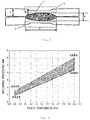
Fig.4 is a schematic view of the relationship between a plate thickness and a welding pressure; -
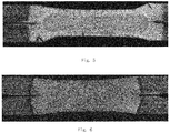
Fig.5 is a metallograph of a typical spot welding section with a process No.1 (conventional spot welding process) in an embodiment; -
Fig.6 is a metallograph of a typical spot welding section of a process No.3 (the spot welding method of the present invention) in an embodiment. - The present invention will be further described below in conjunction with the accompanying drawings and a specific embodiment.
- The present invention discloses a resistance spot welding method of galvanized steel plates with a tensile strength no less than 590Mpa. By the method, the plasticity of welding spot can be improved, and the probability of button pullout failure of the welding spots during broken testing can be increased while the generation of liquid metal embrittlement (LME) cracks during the spot welding of high-strength steel galvanized plates are suppressed.
- As shown in
Fig.2 , in a resistance spot welding method of galvanized high-strength steel with good joint performance, three welding pulses are used within one spot welding schedule; a first welding pulse and a second welding pulse are used for generating a nugget and suppressing the generation of LME cracks, wherein the first welding pulse generates a nugget having a diameter of 3.75T1/2-4.25T1/2, and T represents a plate thickness; the second welding pulse causes the nugget to grow slowly; and a third welding pulse is a tempering pulse, which is used for improving the plasticity of a welding spot. - A time t1 of the first welding pulse is set, and the welding current I1 of the first welding pulse is obtained through tests, and the welding current I1 of the first welding pulse is a welding current upon generating the nugget having the diameter of 3.75T1/2-4.25T1/2 (T=plate thickness). A welding current 12 and a time t2 of the second welding pulse and a welding current I3 and a time t3 of the third welding pulse are calculated by the welding current I1 and the time t1 of the first welding pulse.
- In the present invention, the welding current 12 and the time t2 of the second welding pulse and the welding current I3 and the time t3 of the third welding pulse can be conveniently calculated by the welding current I1 and the time t1 of the first welding pulse obtained through a few tests, so that the spot welding process, which can not only suppress the LME cracks during the spot welding of the high-strength steel galvanized plates, but also can improve the plasticity of the welding spot, is implemented.
- The working principle of the resistance spot welding method of galvanized high-strength steel with good joint performance of the present invention is as follows:
A stress and a suitable temperature range (the range of the galvanized high-strength steel is 700 °C to 950 °C) are two necessary conditions for the generation of the LME cracks. The galvanized high-strength steel has the above two conditions in a spot welding process, and thus generates the LME cracks. - The design idea of the present invention is to avoid the occurrence of the LME cracks by reducing the stress level of a spot welding LME crack sensitive region X, as shown in
Fig.3 . The specific principle is as follows: with the increase of heat input during the spot welding, a diameter D and a height h of the nugget Y increase continuously. Since the high-strength steel, especially ultra-high-strength steel, has the addition of more alloy elements to a base material, it has high electrical resistivity, the heat generation speed during the spot welding is high, and the nugget grows at a high speed. The height h of the nugget grows too fast, so that the thickness T' of the unmelted base material in a plate thickness direction is rapidly decreased, and the size of the thickness T' of the unmelted base material directly affects the cross-sectional area under a load. Therefore, the smaller the thickness T' of the unmelted base material is, the greater the stress is. - In the present invention, the nugget having the diameter of 3.75T1/2-4.25T1/2 (T=the plate thickness) is generated by the first welding pulse. At this time, the nugget is relatively small, the thickness T' of the unmelted base material is relatively large, and no LME crack of spot welding is generated. Then, the second welding pulse with a short time t2 is applied to slowly grow the nugget, thus reducing the decrease speed of the thickness T' of the unmelted base material so as to reduce the stress level of the LME crack sensitive region and avoid the occurrence of the LME cracks.
- The improvement of the plasticity of the welding spot and the increased probability of button pullout failure of the welding spot during the broken testing are achieved by the third welding pulse. The pulse is the tempering pulse, which can effectively reduce the cooling speed of the region of the nugget and reduce the generation of a hardened structure of the joint, thereby improving the plasticity of the joint.
-
1.1 An electrode having an domed surface with ø6mm (plate thickness ≤1.4mm) or ø8mm (plate thickness >1.4mm) is used.
1.2 The welding pressure is set within an enclosed region as shown inFig. 4 according to the plate thickness. A specific method of setting a value of the welding pressure is as follows: the lower limit of the welding pressure Fmin = 3.182T + 0.0364 kN (wherein T represents the plate thickness, its unit is mm, and the range of T is 0.9mm-2.0mm); the upper limit of the welding pressure Fmax =4.091T-0.182 kN (wherein T represents the plate thickness, its unit is mm, and the range of T is 0.9mm-2.0mm).
1.3 Flow rate of cooling water: 2L/min-4L/min.
1.4 The time of C1, C2 and HT (holding time) inFig.2 is set according to Table 1. The interval time between the first welding pulse and the second welding pulse is C1, that is, a first cooling time C1, the interval time between the second welding pulse and the third welding pulse is C2, that is, a second cooling time C2, the holding time HT is a time after the third welding pulse, and their values for steel plates with different thicknesses are respectively set as follows:Table 1 Plate thickness/mm C1 C2 HT 0.9-1.2 1cyc 8cyc 5cyc 1.3-1.6 10cyc 1.7-2.0 12cyc -
- 2.1 The time t1 of the first welding pulse is set according to the plate thickness, and a specific setting method is as follows:
- Plate thickness 0.9-1.2mm: t1: 8-12cyc;
- Plate thickness 1.3-1.6mm: t1: 10-15cyc;
- Plate thickness 1.7-2.0mm: t1: 12-18cyc.
- 2.2 The welding current I1 of the first welding pulse is set. A nugget having a diameter of 3.75T1/2-4.25T1/2(T=plate thickness) is generated. The setting steps of the welding current I1 of the first welding pulse are as follows:
- 2.2.1 The electrode, the pressure, the flow rate of cooling water and the HT are set according to "1 basic parameter setting". C1 and C2 are set as 0.
- 2.2.2 t1 is set according to the method of "2.1".
- 2.2.3 Starting from 4kA, the welding current I1 of the first pulse is sequentially set with 400A as a step length, and two spot welding samples are welded under each current.
- 2.2.4 The spot welding samples in 2.2.3 are destroyed by using a peeling method.
- 2.2.5 The diameter of the nugget of the welding spot of each spot welding sample that is destroyed in step 2.2.4 is measured by using a vernier caliper.
- 2.2.6 The diameters of the nuggets of the two welding spots under the same welding current is averaged, and the corresponding current when the averaged value is closest to the 3.75T1/2-4.25T1/2(T=plate thickness) is the "welding current I1 of the first pulse".
-
- 3.1 The electrode, the pressure, the flow rate of cooling water, C1, C2 and HT are set according to "1 basic parameter setting".
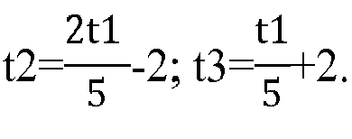
- 3.2 The t2 and t3 are set according to the plate thickness through the t1, and a specific method is as follows:
- Plate thickness 0.9-1.2mm: t1: 8-12cyc;

- Plate thickness 1.3-1.6mm: t1: 10-15cyc;
- Plate thickness 1.7-2.0mm: t1: 12-18cyc;

- Plate thickness 0.9-1.2mm: t1: 8-12cyc;
-
- 4.1 The welding current 12 of the second welding pulse is set according to the welding current I1 of the first welding pulse. The diameter of the nugget is caused to grow slowly, and it is ensured that no welding spatter occurs. A setting method of the welding current 12 of the second welding pulse is as follows:
- Lower limit of 12: I2min=(1.3-0.05t2)I1, wherein t2 is the time of the second welding pulse(unit: cyc);
- Upper limit of 12: I2max = (2.2-0.1t2)I1, wherein t2 is the time of the second welding pulse(unit: cyc).
- 4.2 The welding current I3 of the third welding pulse is set according to the welding current I1 of the first welding pulse. Slow cooling processing is performed on the welding spot to reduce the generation of the hardened structure of the nugget and to improve the plasticity of the welding spot. A setting method of the welding current I3 of the third welding pulse is as follows:
- Lower limit of I3:

- Upper limit of I3: I3max =11.
- Lower limit of I3:
- Spot welding is performed on 1.6 mm hot-diped high-strength steel (the mechanical property and compositions are shown in table 2) by using three spot welding schedules No. 1, No. 2 and No. 3. The LME crack generations and the fracture modes of the welding spot during the broken testing are compared and evaluated. The characteristics and test results of the three spot welding schedules are shown in the Table 3.
Table 2 Compositions and mechanical property of galvanized high-strength steel Plate thickness Mechanical property Chemical composition % Yield strength Tensile strength Elongation at fracture C Si Mn P S 1.6 mm 715 Mpa 1020 Mpa 20% 0.2 1.5 1.8 0.01 0.002 Table 3 Characteristics and results of Spot welding processes No. 1, No. 2 and No. 3 Process serial number Process characteristics Test result No. 1 Conventional spot welding process The welding spot generates severe LME cracks No. 2 The third welding pulse is zero, and the remaining processes are set according to the spot welding method of the present invention The ratio of interfacial fracture at welding spot during the broken testing is high No. 3 The spot welding method according to the present invention is adopted No spot welding LME crack is generated, and the ratio of interfacial fracture at the welding spot during the broken testing is greatly reduced - The detailed results are as follows:
- The spot welding process No. 1 is specifically as shown in Table 4:
Table 4 Spot welding process No. 1 Plate thickness Diameter of end surface of electrode Welding pressure First pulse First cooling time Second pulse Second cooling time Third pulse Holding time Flow rate of cooling water Time Current Time Current Time Current 1.6mm 6mm 3.6KN 6cyc I1 1cyc 6cyc I2 1cyc 6cyc I3 5cyc 2L/min Note: I1=l2=l3 in the table - Through the metallographic, severe liquid metal embrittlement (LME) cracks are found in the entire welded region.
Fig. 5 is a typical metallograph thereof. - The spot welding process No.2 is as follows:
Table 5 Spot welding process No.2 Plate thickness Diameter of end surface of electrode Welding pressure First pulse First cooling time Second pulse Second cooling time Third pulse Holding time Flow rate of cooling water Time Current Time Current Time Current 1.6mm 8mm 5.5kN 15 eye 8.0kA lcyc 4cyc 8.8-14.4kA 0 0 0 5cyc 2L/min - By this welding method, during the broken testing, the fracture mode of the welding spot is mainly interfacial fracture. Although the tensile-shear strength (TSS) and cross tensile strength (CTS) of the welding spot meet the requirements, the welding spot after the TSS test is almost entirely with interfacial fracture, and the ratio of interfacial fracture after the CTS test is also less than 50%.
- The spot welding process No.3 is as follows:
Table 6 Spot welding process No.3 Plate thickness Diameter of end surface of electrode Welding pressure First pulse First cooling time Second pulse Second cooling time Third pulse Holding time Flow rate of cooling water Time Current Time Current Time Current 1.6mm 8mm 5.5kN 15 cyc 8.0kA 1cyc 4cyc 8.8-14.4 kA 10cyc 5cyc 5.3kA 5cyc 2L/min - By this method, the liquid metal embrittlement (LME) crack is not found in the entire welded region through the metallographic. The typical metallograph thereof is as shown in
Fig.6 . - At the same time, by this process, the tensile-shear strength (TSS) and corss tensile strength (CTS) of the welding spot meet the requirements, the fracture mode detected after the CTS test is all button pullout failure, and the ratio of button pullout failure at the welding spot detected after the TSS detection is also above 70%, which is much better than the result when the slow cooling pulse is not applied.
- The above descriptions are only preferred embodiments of the present invention, and are not intended to limit the protection scope of the present invention. Therefore, any modifications, equivalents, improvements and the like made within the spirit and principle of the present invention should be encompassed within the protection scope of the present invention.
Claims (3)
- A resistance spot welding method of galvanized high-strength steel with good joint performance, characterized by that:three welding pulses are used within one spot welding schedule;a first welding pulse and a second welding pulse are used for generating a nugget andsuppressing the generation of liquid metal embrittlement (LME) cracks, wherein the first welding pulse generates a nugget having a diameter of 3.75T1/2-4.25T1/2 in which T represents a plate thickness;the second welding pulse causes the nugget to grow slowly; anda third welding pulse which is a tempering pulse is used for improving plasticity of a welding spot.
- The resistance spot welding method of galvanized high-strength steel with good joint performance according to claim 1, wherein a time t1 of the first welding pulse is set and a welding current I1 of the first welding pulse is obtained through tests, and the welding current I1 of the first welding pulse is a welding current upon generating the nugget having the diameter of 3.75T1/2-4.25T1/2; and
a welding current 12 and a time t2 of the second welding pulse, and a welding current I3 and a time t3 of the third welding pulse are calculated by the welding current I1 and the time t1 of the first welding pulse. - The resistance spot welding method of galvanized high-strength steel with good joint performance according to claim 2, wherein
for the plate thickness 0.9-1.2 mm, the time t1 of the first welding pulse is set as 8-12 cyc, wherein cyc represents a time unit, 1 cyc = 0.02 seconds, and the welding current I1 of the first welding pulse is obtained through tests;
for the plate thickness 1.3-1.6 mm, the time t1 of the first welding pulse is set as 10-15 cyc, and the welding current I1 of the first welding pulse is obtained through tests; for the plate thickness 1.7-2.0 mm, the time t1 of the first welding pulse is set as 12-18 cyc, and the welding current I1 of the first welding pulse is obtained through tests; correspondingly:for the plate thickness 0.9-1.2 mm, the time of the second welding pulse is set as
 for the plate thickness 1.3-1.6 mm, the time of the second welding pulse is set as t2=
 for the plate thickness 1.7-2.0 mm, the time of the second welding pulse is set as

a specific setting method of the current 12 of the second welding pulse is as follows:a lower limit of 12: I2min=(1.3-0.05t2)I1, an upper limit of 12: I2max=(2.2-0.1t2)I1;a specific setting method of the current I3 of the third welding pulse current I3 is as follows:a lower limit of I3: an interval time between the first welding pulse and the second welding pulse is C1 which is a first cooling time ,an interval time between the second welding pulse and the third welding pulse is C2 which is a second cooling time,a holding time HT is a time after the third welding pulse, andfor steel plates with different thicknesses, values of C1, C2 and HT are respectively set as follows:plate thickness 0.9-1.2 mm, C1=1 cyc, C2=8 cyc, HT=5 cyc;plate thickness 1.3-1.6 mm, C1=1 cyc, C2=10 cyc, HT=5 cyc;plate thickness 1.7-2.0 mm, C1=1 cyc, C2=12 cyc, HT=5 cyc.
Applications Claiming Priority (2)
| Application Number | Priority Date | Filing Date | Title |
|---|---|---|---|
| CN201610963996.5A CN108015401B (en) | 2016-11-04 | 2016-11-04 | Resistance spot welding method for galvanized high-strength steel with good joint performance |
| PCT/CN2017/104710 WO2018082425A1 (en) | 2016-11-04 | 2017-09-30 | Method for welding zinc-coated high-strength steel resistance spot having good joint properties |
Publications (3)
| Publication Number | Publication Date |
|---|---|
| EP3536435A1 true EP3536435A1 (en) | 2019-09-11 |
| EP3536435A4 EP3536435A4 (en) | 2020-08-19 |
| EP3536435B1 EP3536435B1 (en) | 2024-11-20 |
Family
ID=62075755
Family Applications (1)
| Application Number | Title | Priority Date | Filing Date |
|---|---|---|---|
| EP17868072.4A Active EP3536435B1 (en) | 2016-11-04 | 2017-09-30 | Method for welding zinc-coated high-strength steel resistance spot having good joint properties |
Country Status (8)
| Country | Link |
|---|---|
| US (1) | US11167370B2 (en) |
| EP (1) | EP3536435B1 (en) |
| JP (1) | JP7019687B2 (en) |
| CN (1) | CN108015401B (en) |
| AU (1) | AU2017352642B2 (en) |
| BR (1) | BR112019008699B1 (en) |
| ES (1) | ES3002385T3 (en) |
| WO (1) | WO2018082425A1 (en) |
Families Citing this family (22)
| Publication number | Priority date | Publication date | Assignee | Title |
|---|---|---|---|---|
| US11007598B2 (en) * | 2015-09-03 | 2021-05-18 | Nippon Steel Corporation | Spot welding method |
| CN108890110A (en) * | 2018-09-10 | 2018-11-27 | 东北大学 | A kind of resistance spot welding process improving Q&P steel welded joint quality |
| CN109079304A (en) * | 2018-10-10 | 2018-12-25 | 鞍钢股份有限公司 | Spot welding process method for high-carbon equivalent cold-rolled dual-phase steel |
| CN109352155A (en) * | 2018-11-16 | 2019-02-19 | 上海交通大学 | Welding process for improving welding quality of resistance spot welding of galvanized ultra-high strength steel |
| CN109317801A (en) * | 2018-12-03 | 2019-02-12 | 闫宇 | Micro spot welding process for nickel-plated copper wire harness and copper plate |
| WO2020212741A1 (en) * | 2019-04-19 | 2020-10-22 | Arcelormittal | A method for resistance spot welding of zinc-coated high strength steels |
| CN114160944B (en) * | 2020-09-11 | 2023-03-31 | 宝山钢铁股份有限公司 | Weld joint thickness prediction method for narrow lap resistance welding machine |
| CN112846470A (en) * | 2021-01-05 | 2021-05-28 | 中国科学院上海光学精密机械研究所 | Resistance spot welding method containing ultra-strong hot forming steel plate matching |
| CN113134671B (en) * | 2021-03-22 | 2022-11-18 | 首钢集团有限公司 | A resistance spot welding method for welding plate groups |
| JP7545096B2 (en) * | 2021-04-05 | 2024-09-04 | 日本製鉄株式会社 | Resistance spot welded joint and method for manufacturing resistance spot welded joint |
| MX2023013724A (en) | 2021-05-26 | 2023-11-28 | Kobe Steel Ltd | High-strength alloyed hot-dip galvanized steel sheet and manufacturing method therefor. |
| CN113441826A (en) * | 2021-07-16 | 2021-09-28 | 上海交通大学 | Spot welding process for inhibiting liquid metal brittle cracks of galvanized high-strength steel resistance spot welding joint |
| CN114101883B (en) * | 2021-11-26 | 2023-06-02 | 中国科学院上海光学精密机械研究所 | Resistance spot welding method for low-melting-point coated steel workpiece |
| CN114850644A (en) * | 2022-05-06 | 2022-08-05 | 本钢板材股份有限公司 | Resistance spot welding method for 2000 MPa-level hot-formed steel plate |
| EP4484044B1 (en) | 2022-06-03 | 2026-03-25 | JFE Steel Corporation | Welded joint, welded member, method of producing same, and resistance spot welding method |
| CN117802400A (en) | 2022-09-23 | 2024-04-02 | 宝山钢铁股份有限公司 | Coated ultra-high-strength steel with low spot welding crack sensitivity and manufacturing method thereof |
| JP7846376B2 (en) * | 2022-11-24 | 2026-04-15 | 日本製鉄株式会社 | Method for manufacturing spot welded joints and spot welded joints |
| CN118326245A (en) | 2023-01-10 | 2024-07-12 | 宝山钢铁股份有限公司 | A kind of GIP steel with excellent spot welding performance and its manufacturing method |
| CN118703903A (en) | 2023-03-27 | 2024-09-27 | 宝山钢铁股份有限公司 | A kind of ultra-high strength steel with coating having excellent spot welding performance and its manufacturing method |
| JP7648019B2 (en) * | 2023-04-03 | 2025-03-18 | Jfeスチール株式会社 | Resistance spot welding method and method for manufacturing welded parts |
| CN116673580B (en) * | 2023-06-20 | 2026-03-10 | 本钢板材股份有限公司 | Method for improving performance of resistance spot welding joint of pickled plate |
| CN116586734B (en) * | 2023-06-30 | 2026-03-17 | 本钢板材股份有限公司 | A method for improving the performance of resistance spot welded joints of hot-formed steel with thick iron oxide scale |
Family Cites Families (19)
| Publication number | Priority date | Publication date | Assignee | Title |
|---|---|---|---|---|
| US4503311A (en) * | 1983-05-25 | 1985-03-05 | General Motors Corporation | Method and apparatus for detecting the onset of melting in a resistance spot weld |
| US4678887A (en) * | 1986-07-09 | 1987-07-07 | General Motors Corporation | Method and apparatus for resistance welding |
| CN1028320C (en) * | 1993-01-17 | 1995-05-03 | 河北工学院 | Resistance spot welding process for cast iron and steel |
| US6903298B2 (en) * | 2003-08-25 | 2005-06-07 | General Motors Corporation | Resistance welding control method |
| CN200945545Y (en) * | 2006-08-30 | 2007-09-12 | 吕华兵 | Double impulsed spot welding machine |
| ATE504384T1 (en) * | 2006-11-14 | 2011-04-15 | Corus Staal Bv | SPOT WELDING PROCESS AND SPOT WELDED SURFACE MATERIAL |
| PL217717B1 (en) * | 2011-07-05 | 2014-08-29 | Inst Spawalnictwa | Method of welding sheets of high strength, especially TRIP and DP |
| CN102500936A (en) | 2011-10-12 | 2012-06-20 | 北京工业大学 | High-strength steel resistance and laser combined spot welding method |
| CN102500901B (en) * | 2011-11-16 | 2014-04-16 | 上海交通大学 | Composite pulsation spot welding process and system |
| CN102489859B (en) | 2011-12-16 | 2013-08-14 | 长春三友汽车部件制造有限公司 | Method for improving mechanical property of advanced high-strength steel spot welding joint |
| CN102581459B (en) * | 2012-03-07 | 2014-06-25 | 上海交通大学 | Electric resistance welding method for variable-thickness ultra-high strength hot formed steel plate and low-carbon steel plate |
| US9737956B2 (en) * | 2013-06-14 | 2017-08-22 | GM Global Technology Operations LLC | Resistance spot welding thin gauge steels |
| CN105358284B (en) * | 2013-07-11 | 2018-12-14 | 新日铁住金株式会社 | Resistance spot welding method |
| KR101567652B1 (en) * | 2013-12-20 | 2015-11-09 | 현대자동차주식회사 | Spot welding method for high strength steel sheet |
| KR101887789B1 (en) * | 2013-12-20 | 2018-08-10 | 신닛테츠스미킨 카부시키카이샤 | Resistance spot welding method |
| US10279418B2 (en) * | 2014-07-16 | 2019-05-07 | Honda Motor Co., Ltd. | Method and apparatus for resistive spot welding |
| KR101657781B1 (en) * | 2014-11-25 | 2016-09-20 | 주식회사 포스코 | METHOD FOR RESISTANCE SPOT WELDING FOR Zn PLATED STEEL SHEET |
| WO2016093340A1 (en) * | 2014-12-12 | 2016-06-16 | 新日鐵住金株式会社 | Power-source device, joining system, and conductive processing method |
| CN218376364U (en) * | 2022-09-16 | 2023-01-24 | 马斯特钻探工程(常州)有限公司 | Drill column type centralizer |
-
2016
- 2016-11-04 CN CN201610963996.5A patent/CN108015401B/en active Active
-
2017
- 2017-09-30 AU AU2017352642A patent/AU2017352642B2/en active Active
- 2017-09-30 BR BR112019008699-4A patent/BR112019008699B1/en active IP Right Grant
- 2017-09-30 ES ES17868072T patent/ES3002385T3/en active Active
- 2017-09-30 JP JP2019522466A patent/JP7019687B2/en active Active
- 2017-09-30 WO PCT/CN2017/104710 patent/WO2018082425A1/en not_active Ceased
- 2017-09-30 EP EP17868072.4A patent/EP3536435B1/en active Active
- 2017-09-30 US US16/342,263 patent/US11167370B2/en active Active
Also Published As
| Publication number | Publication date |
|---|---|
| EP3536435A4 (en) | 2020-08-19 |
| CN108015401B (en) | 2020-06-23 |
| AU2017352642B2 (en) | 2022-09-08 |
| AU2017352642A1 (en) | 2019-05-16 |
| BR112019008699B1 (en) | 2023-02-28 |
| ES3002385T3 (en) | 2025-03-06 |
| US11167370B2 (en) | 2021-11-09 |
| WO2018082425A1 (en) | 2018-05-11 |
| CN108015401A (en) | 2018-05-11 |
| EP3536435B1 (en) | 2024-11-20 |
| BR112019008699A2 (en) | 2019-10-08 |
| US20190321907A1 (en) | 2019-10-24 |
| JP2019536631A (en) | 2019-12-19 |
| JP7019687B2 (en) | 2022-02-15 |
Similar Documents
| Publication | Publication Date | Title |
|---|---|---|
| EP3536435B1 (en) | Method for welding zinc-coated high-strength steel resistance spot having good joint properties | |
| EP3812079B1 (en) | Method for manufacturing equal-strength steel thin-wall welding component with aluminum or aluminum-alloy plating | |
| EP2783782B1 (en) | Resistance spot welding joint | |
| CA2909397C (en) | Spot welding method | |
| EP3028799A1 (en) | Arc spot weld joint and method for producing same | |
| CN115070186B (en) | A kind of hot-dip galvanized dual-phase steel resistance spot welding method | |
| EP3797922A1 (en) | Laser-welded lap joint, method for producing laser-welded lap joint, and structural component for vehicle | |
| CN106271018A (en) | A kind of method improving big thick and high-strength degree alloy explosive welding solderability | |
| CN113441826A (en) | Spot welding process for inhibiting liquid metal brittle cracks of galvanized high-strength steel resistance spot welding joint | |
| EP4242357A1 (en) | Fe-electroplated steel sheet, electrodeposition coated steel sheet, automobile component, method for manufacturing electrodeposition coated steel sheet, and method for manufacturing fe-electroplated steel sheet | |
| KR102200155B1 (en) | Method for manufacturing of welded structure, and welded structure manufactured by thereof | |
| JP7560006B1 (en) | Projection welded joint and its manufacturing method | |
| EP4567145A1 (en) | Method for manufacturing spot welded joint, and spot welded joint | |
| EP3162489B1 (en) | Method of butt welding steel plates and butt weld joint of steel plates | |
| JP4173990B2 (en) | Zinc-based alloy-plated steel for welding and its ERW steel pipe | |
| CN118371837A (en) | A resistance spot welding method for 1500MPa grade oxidation-resistant hot-formed steel and aluminum-silicon coated hot-formed steel | |
| CN111069751A (en) | Application of low-carbon gas shield welding wire in welding of 40Cr plate and Q355 plate | |
| EP3995246A1 (en) | Resistance spot welding method and method of manufacturing resistance spot welded joint | |
| CN102419290A (en) | Method for judging laser welding strength of heat-treatment-improved martensitic aged steel belt | |
| KR101988769B1 (en) | Electrode for spot welding | |
| EP4484045B1 (en) | Welded joint, welded member, method of producing same, and resistance spot welding method | |
| EP4656321A1 (en) | Projection welded joint and manufacturing method therefor | |
| EP4656322A1 (en) | Projection welded joint and method for manufacturing same | |
| CN119260134B (en) | Preparation method of nickel-based wrought superalloy strip capable of increasing single-coil weight | |
| EP3682997B1 (en) | Resistance spot welding method |
Legal Events
| Date | Code | Title | Description |
|---|---|---|---|
| STAA | Information on the status of an ep patent application or granted ep patent |
Free format text: STATUS: THE INTERNATIONAL PUBLICATION HAS BEEN MADE |
|
| PUAI | Public reference made under article 153(3) epc to a published international application that has entered the european phase |
Free format text: ORIGINAL CODE: 0009012 |
|
| STAA | Information on the status of an ep patent application or granted ep patent |
Free format text: STATUS: REQUEST FOR EXAMINATION WAS MADE |
|
| 17P | Request for examination filed |
Effective date: 20190502 |
|
| AK | Designated contracting states |
Kind code of ref document: A1 Designated state(s): AL AT BE BG CH CY CZ DE DK EE ES FI FR GB GR HR HU IE IS IT LI LT LU LV MC MK MT NL NO PL PT RO RS SE SI SK SM TR |
|
| AX | Request for extension of the european patent |
Extension state: BA ME |
|
| DAV | Request for validation of the european patent (deleted) | ||
| DAX | Request for extension of the european patent (deleted) | ||
| A4 | Supplementary search report drawn up and despatched |
Effective date: 20200720 |
|
| RIC1 | Information provided on ipc code assigned before grant |
Ipc: B23K 11/11 20060101AFI20200714BHEP |
|
| STAA | Information on the status of an ep patent application or granted ep patent |
Free format text: STATUS: EXAMINATION IS IN PROGRESS |
|
| 17Q | First examination report despatched |
Effective date: 20220603 |
|
| GRAP | Despatch of communication of intention to grant a patent |
Free format text: ORIGINAL CODE: EPIDOSNIGR1 |
|
| STAA | Information on the status of an ep patent application or granted ep patent |
Free format text: STATUS: GRANT OF PATENT IS INTENDED |
|
| INTG | Intention to grant announced |
Effective date: 20240711 |
|
| GRAS | Grant fee paid |
Free format text: ORIGINAL CODE: EPIDOSNIGR3 |
|
| P01 | Opt-out of the competence of the unified patent court (upc) registered |
Free format text: CASE NUMBER: APP_50301/2024 Effective date: 20240905 |
|
| GRAA | (expected) grant |
Free format text: ORIGINAL CODE: 0009210 |
|
| STAA | Information on the status of an ep patent application or granted ep patent |
Free format text: STATUS: THE PATENT HAS BEEN GRANTED |
|
| AK | Designated contracting states |
Kind code of ref document: B1 Designated state(s): AL AT BE BG CH CY CZ DE DK EE ES FI FR GB GR HR HU IE IS IT LI LT LU LV MC MK MT NL NO PL PT RO RS SE SI SK SM TR |
|
| REG | Reference to a national code |
Ref country code: GB Ref legal event code: FG4D |
|
| REG | Reference to a national code |
Ref country code: CH Ref legal event code: EP |
|
| REG | Reference to a national code |
Ref country code: DE Ref legal event code: R096 Ref document number: 602017086298 Country of ref document: DE |
|
| REG | Reference to a national code |
Ref country code: IE Ref legal event code: FG4D |
|
| REG | Reference to a national code |
Ref country code: SE Ref legal event code: TRGR |
|
| REG | Reference to a national code |
Ref country code: ES Ref legal event code: FG2A Ref document number: 3002385 Country of ref document: ES Kind code of ref document: T3 Effective date: 20250306 |
|
| REG | Reference to a national code |
Ref country code: LT Ref legal event code: MG9D |
|
| REG | Reference to a national code |
Ref country code: NL Ref legal event code: MP Effective date: 20241120 |
|
| PG25 | Lapsed in a contracting state [announced via postgrant information from national office to epo] |
Ref country code: PT Free format text: LAPSE BECAUSE OF FAILURE TO SUBMIT A TRANSLATION OF THE DESCRIPTION OR TO PAY THE FEE WITHIN THE PRESCRIBED TIME-LIMIT Effective date: 20250320 Ref country code: HR Free format text: LAPSE BECAUSE OF FAILURE TO SUBMIT A TRANSLATION OF THE DESCRIPTION OR TO PAY THE FEE WITHIN THE PRESCRIBED TIME-LIMIT Effective date: 20241120 Ref country code: IS Free format text: LAPSE BECAUSE OF FAILURE TO SUBMIT A TRANSLATION OF THE DESCRIPTION OR TO PAY THE FEE WITHIN THE PRESCRIBED TIME-LIMIT Effective date: 20250320 |
|
| PG25 | Lapsed in a contracting state [announced via postgrant information from national office to epo] |
Ref country code: FI Free format text: LAPSE BECAUSE OF FAILURE TO SUBMIT A TRANSLATION OF THE DESCRIPTION OR TO PAY THE FEE WITHIN THE PRESCRIBED TIME-LIMIT Effective date: 20241120 Ref country code: NL Free format text: LAPSE BECAUSE OF FAILURE TO SUBMIT A TRANSLATION OF THE DESCRIPTION OR TO PAY THE FEE WITHIN THE PRESCRIBED TIME-LIMIT Effective date: 20241120 |
|
| REG | Reference to a national code |
Ref country code: AT Ref legal event code: MK05 Ref document number: 1743145 Country of ref document: AT Kind code of ref document: T Effective date: 20241120 |
|
| PG25 | Lapsed in a contracting state [announced via postgrant information from national office to epo] |
Ref country code: BG Free format text: LAPSE BECAUSE OF FAILURE TO SUBMIT A TRANSLATION OF THE DESCRIPTION OR TO PAY THE FEE WITHIN THE PRESCRIBED TIME-LIMIT Effective date: 20241120 |
|
| PG25 | Lapsed in a contracting state [announced via postgrant information from national office to epo] |
Ref country code: NO Free format text: LAPSE BECAUSE OF FAILURE TO SUBMIT A TRANSLATION OF THE DESCRIPTION OR TO PAY THE FEE WITHIN THE PRESCRIBED TIME-LIMIT Effective date: 20250220 |
|
| PG25 | Lapsed in a contracting state [announced via postgrant information from national office to epo] |
Ref country code: LV Free format text: LAPSE BECAUSE OF FAILURE TO SUBMIT A TRANSLATION OF THE DESCRIPTION OR TO PAY THE FEE WITHIN THE PRESCRIBED TIME-LIMIT Effective date: 20241120 Ref country code: GR Free format text: LAPSE BECAUSE OF FAILURE TO SUBMIT A TRANSLATION OF THE DESCRIPTION OR TO PAY THE FEE WITHIN THE PRESCRIBED TIME-LIMIT Effective date: 20250221 Ref country code: AT Free format text: LAPSE BECAUSE OF FAILURE TO SUBMIT A TRANSLATION OF THE DESCRIPTION OR TO PAY THE FEE WITHIN THE PRESCRIBED TIME-LIMIT Effective date: 20241120 |
|
| PG25 | Lapsed in a contracting state [announced via postgrant information from national office to epo] |
Ref country code: PL Free format text: LAPSE BECAUSE OF FAILURE TO SUBMIT A TRANSLATION OF THE DESCRIPTION OR TO PAY THE FEE WITHIN THE PRESCRIBED TIME-LIMIT Effective date: 20241120 |
|
| PG25 | Lapsed in a contracting state [announced via postgrant information from national office to epo] |
Ref country code: RS Free format text: LAPSE BECAUSE OF FAILURE TO SUBMIT A TRANSLATION OF THE DESCRIPTION OR TO PAY THE FEE WITHIN THE PRESCRIBED TIME-LIMIT Effective date: 20250220 |
|
| PG25 | Lapsed in a contracting state [announced via postgrant information from national office to epo] |
Ref country code: SM Free format text: LAPSE BECAUSE OF FAILURE TO SUBMIT A TRANSLATION OF THE DESCRIPTION OR TO PAY THE FEE WITHIN THE PRESCRIBED TIME-LIMIT Effective date: 20241120 |
|
| PG25 | Lapsed in a contracting state [announced via postgrant information from national office to epo] |
Ref country code: DK Free format text: LAPSE BECAUSE OF FAILURE TO SUBMIT A TRANSLATION OF THE DESCRIPTION OR TO PAY THE FEE WITHIN THE PRESCRIBED TIME-LIMIT Effective date: 20241120 |
|
| PG25 | Lapsed in a contracting state [announced via postgrant information from national office to epo] |
Ref country code: EE Free format text: LAPSE BECAUSE OF FAILURE TO SUBMIT A TRANSLATION OF THE DESCRIPTION OR TO PAY THE FEE WITHIN THE PRESCRIBED TIME-LIMIT Effective date: 20241120 |
|
| PG25 | Lapsed in a contracting state [announced via postgrant information from national office to epo] |
Ref country code: RO Free format text: LAPSE BECAUSE OF FAILURE TO SUBMIT A TRANSLATION OF THE DESCRIPTION OR TO PAY THE FEE WITHIN THE PRESCRIBED TIME-LIMIT Effective date: 20241120 |
|
| PG25 | Lapsed in a contracting state [announced via postgrant information from national office to epo] |
Ref country code: SK Free format text: LAPSE BECAUSE OF FAILURE TO SUBMIT A TRANSLATION OF THE DESCRIPTION OR TO PAY THE FEE WITHIN THE PRESCRIBED TIME-LIMIT Effective date: 20241120 |
|
| PG25 | Lapsed in a contracting state [announced via postgrant information from national office to epo] |
Ref country code: CZ Free format text: LAPSE BECAUSE OF FAILURE TO SUBMIT A TRANSLATION OF THE DESCRIPTION OR TO PAY THE FEE WITHIN THE PRESCRIBED TIME-LIMIT Effective date: 20241120 |
|
| REG | Reference to a national code |
Ref country code: DE Ref legal event code: R097 Ref document number: 602017086298 Country of ref document: DE |
|
| PLBE | No opposition filed within time limit |
Free format text: ORIGINAL CODE: 0009261 |
|
| STAA | Information on the status of an ep patent application or granted ep patent |
Free format text: STATUS: NO OPPOSITION FILED WITHIN TIME LIMIT |
|
| PGFP | Annual fee paid to national office [announced via postgrant information from national office to epo] |
Ref country code: DE Payment date: 20250916 Year of fee payment: 9 |
|
| PGFP | Annual fee paid to national office [announced via postgrant information from national office to epo] |
Ref country code: IT Payment date: 20250909 Year of fee payment: 9 |
|
| PGFP | Annual fee paid to national office [announced via postgrant information from national office to epo] |
Ref country code: GB Payment date: 20250919 Year of fee payment: 9 |
|
| PGFP | Annual fee paid to national office [announced via postgrant information from national office to epo] |
Ref country code: FR Payment date: 20250929 Year of fee payment: 9 |
|
| PGFP | Annual fee paid to national office [announced via postgrant information from national office to epo] |
Ref country code: SE Payment date: 20250925 Year of fee payment: 9 |
|
| 26N | No opposition filed |
Effective date: 20250821 |
|
| PGFP | Annual fee paid to national office [announced via postgrant information from national office to epo] |
Ref country code: ES Payment date: 20251015 Year of fee payment: 9 |
|
| REG | Reference to a national code |
Ref country code: CH Ref legal event code: H13 Free format text: ST27 STATUS EVENT CODE: U-0-0-H10-H13 (AS PROVIDED BY THE NATIONAL OFFICE) Effective date: 20260504 |
|
| PG25 | Lapsed in a contracting state [announced via postgrant information from national office to epo] |
Ref country code: LU Free format text: LAPSE BECAUSE OF NON-PAYMENT OF DUE FEES Effective date: 20250930 |
|
| REG | Reference to a national code |
Ref country code: BE Ref legal event code: MM Effective date: 20250930 |
|
| PG25 | Lapsed in a contracting state [announced via postgrant information from national office to epo] |
Ref country code: LT Free format text: LAPSE BECAUSE OF FAILURE TO SUBMIT A TRANSLATION OF THE DESCRIPTION OR TO PAY THE FEE WITHIN THE PRESCRIBED TIME-LIMIT Effective date: 20241120 |
|
| PG25 | Lapsed in a contracting state [announced via postgrant information from national office to epo] |
Ref country code: MC Free format text: LAPSE BECAUSE OF FAILURE TO SUBMIT A TRANSLATION OF THE DESCRIPTION OR TO PAY THE FEE WITHIN THE PRESCRIBED TIME-LIMIT Effective date: 20241120 |
|
| PG25 | Lapsed in a contracting state [announced via postgrant information from national office to epo] |
Ref country code: BE Free format text: LAPSE BECAUSE OF NON-PAYMENT OF DUE FEES Effective date: 20250930 Ref country code: CH Free format text: LAPSE BECAUSE OF NON-PAYMENT OF DUE FEES Effective date: 20250930 Ref country code: IE Free format text: LAPSE BECAUSE OF NON-PAYMENT OF DUE FEES Effective date: 20250930 |