EP3536183A1 - Shoe sole and method for manufacturing sole - Google Patents
Shoe sole and method for manufacturing sole Download PDFInfo
- Publication number
- EP3536183A1 EP3536183A1 EP16924292.2A EP16924292A EP3536183A1 EP 3536183 A1 EP3536183 A1 EP 3536183A1 EP 16924292 A EP16924292 A EP 16924292A EP 3536183 A1 EP3536183 A1 EP 3536183A1
- Authority
- EP
- European Patent Office
- Prior art keywords
- sole
- reinforcement fiber
- base
- projection
- resin plate
- Prior art date
- Legal status (The legal status is an assumption and is not a legal conclusion. Google has not performed a legal analysis and makes no representation as to the accuracy of the status listed.)
- Granted
Links
Images




Classifications
-
- A—HUMAN NECESSITIES
- A43—FOOTWEAR
- A43B—CHARACTERISTIC FEATURES OF FOOTWEAR; PARTS OF FOOTWEAR
- A43B13/00—Soles; Sole-and-heel integral units
- A43B13/14—Soles; Sole-and-heel integral units characterised by the constructive form
- A43B13/22—Soles made slip-preventing or wear-resisting, e.g. by impregnation or spreading a wear-resisting layer
- A43B13/24—Soles made slip-preventing or wear-resisting, e.g. by impregnation or spreading a wear-resisting layer by use of insertions
- A43B13/26—Soles made slip-preventing or wear-resisting, e.g. by impregnation or spreading a wear-resisting layer by use of insertions projecting beyond the sole surface
-
- A—HUMAN NECESSITIES
- A43—FOOTWEAR
- A43B—CHARACTERISTIC FEATURES OF FOOTWEAR; PARTS OF FOOTWEAR
- A43B13/00—Soles; Sole-and-heel integral units
- A43B13/02—Soles; Sole-and-heel integral units characterised by the material
- A43B13/026—Composites, e.g. carbon fibre or aramid fibre; the sole, one or more sole layers or sole part being made of a composite
-
- A—HUMAN NECESSITIES
- A43—FOOTWEAR
- A43B—CHARACTERISTIC FEATURES OF FOOTWEAR; PARTS OF FOOTWEAR
- A43B13/00—Soles; Sole-and-heel integral units
- A43B13/14—Soles; Sole-and-heel integral units characterised by the constructive form
- A43B13/22—Soles made slip-preventing or wear-resisting, e.g. by impregnation or spreading a wear-resisting layer
-
- B—PERFORMING OPERATIONS; TRANSPORTING
- B29—WORKING OF PLASTICS; WORKING OF SUBSTANCES IN A PLASTIC STATE IN GENERAL
- B29D—PRODUCING PARTICULAR ARTICLES FROM PLASTICS OR FROM SUBSTANCES IN A PLASTIC STATE
- B29D35/00—Producing footwear
- B29D35/0054—Producing footwear by compression moulding, vulcanising or the like; Apparatus therefor
-
- B—PERFORMING OPERATIONS; TRANSPORTING
- B29—WORKING OF PLASTICS; WORKING OF SUBSTANCES IN A PLASTIC STATE IN GENERAL
- B29D—PRODUCING PARTICULAR ARTICLES FROM PLASTICS OR FROM SUBSTANCES IN A PLASTIC STATE
- B29D35/00—Producing footwear
- B29D35/12—Producing parts thereof, e.g. soles, heels, uppers, by a moulding technique
- B29D35/14—Multilayered parts
- B29D35/142—Soles
-
- B—PERFORMING OPERATIONS; TRANSPORTING
- B32—LAYERED PRODUCTS
- B32B—LAYERED PRODUCTS, i.e. PRODUCTS BUILT-UP OF STRATA OF FLAT OR NON-FLAT, e.g. CELLULAR OR HONEYCOMB, FORM
- B32B5/00—Layered products characterised by the non- homogeneity or physical structure, i.e. comprising a fibrous, filamentary, particulate or foam layer; Layered products characterised by having a layer differing constitutionally or physically in different parts
-
- C—CHEMISTRY; METALLURGY
- C08—ORGANIC MACROMOLECULAR COMPOUNDS; THEIR PREPARATION OR CHEMICAL WORKING-UP; COMPOSITIONS BASED THEREON
- C08J—WORKING-UP; GENERAL PROCESSES OF COMPOUNDING; AFTER-TREATMENT NOT COVERED BY SUBCLASSES C08B, C08C, C08F, C08G or C08H
- C08J5/00—Manufacture of articles or shaped materials containing macromolecular substances
- C08J5/04—Reinforcing macromolecular compounds with loose or coherent fibrous material
-
- B—PERFORMING OPERATIONS; TRANSPORTING
- B29—WORKING OF PLASTICS; WORKING OF SUBSTANCES IN A PLASTIC STATE IN GENERAL
- B29K—INDEXING SCHEME ASSOCIATED WITH SUBCLASSES B29B, B29C OR B29D, RELATING TO MOULDING MATERIALS OR TO MATERIALS FOR MOULDS, REINFORCEMENTS, FILLERS OR PREFORMED PARTS, e.g. INSERTS
- B29K2101/00—Use of unspecified macromolecular compounds as moulding material
- B29K2101/12—Thermoplastic materials
-
- B—PERFORMING OPERATIONS; TRANSPORTING
- B32—LAYERED PRODUCTS
- B32B—LAYERED PRODUCTS, i.e. PRODUCTS BUILT-UP OF STRATA OF FLAT OR NON-FLAT, e.g. CELLULAR OR HONEYCOMB, FORM
- B32B2437/00—Clothing
- B32B2437/02—Gloves, shoes
Definitions
- the present invention relates to a sole of a shoe having projections such as spikes and cleats, and a method for manufacturing such a sole.
- a sole By forming a sole from reinforcement fiber covered by a matrix resin, e.g., a pre-preg layer, it is possible to increase the rigidity of the sole and reduce the weight of the sole. Such reduction in the weight of the spike sole is important for football sports, etc., as well as for track-and-field spike shoes.
- a matrix resin e.g., a pre-preg layer
- the spikes of these patent documents are made of metal. Such metal spikes need to be bonded to a resin-made sole. The metal spikes may possibly come off the sole.
- a sole of a shoe of the present invention includes:
- the projection projecting from the first base includes as its main component the same first thermoplastic resin as the first base. There will be no need to bond projections such as spikes or cleats to the sole, and the projections will be unlikely to come off the sole.
- the first reinforcement fiber is oriented while being bent from the first base toward the projection, thereby reinforcing an area at the base of the projection. While a great moment acts upon the base area while running, the first reinforcement fiber will serve as a great reaction force against the moment. This will therefore improve the strength of the area at the base of the projection.
- projections also include thorn-like small projections as well as spikes and cleats.
- thermoplastic resin component As used herein "as its main component” means that the thermoplastic resin component at least has a greater quantity (greater weight) than other resin components.
- the weight ratio of the thermoplastic resin component, which is the main component is preferably 50 to 100 wt%, more preferably 60 to 100 wt%, and most preferably 70 to 100 wt%, of the entire resin component of the first base and the projections.
- first base and the projections on the ground side or the first base on the foot side are laminated with a second resin, it is necessary to determine whether or not it is the main component while excluding the second resin.
- the type of the first thermoplastic resin may be a thermoplastic polyamide resin, a urethane resin, an epoxy resin, a polypropylene resin, or the like, for example.
- One resin component may be used alone, or two or more may be used in combination.
- a carbon fiber, a boron fiber, an aramid fiber, a glass fiber, or the like may be employed as the reinforcement fiber.
- One reinforcement fiber may be employed, or two or more may be employed.
- the first reinforcement fiber and the second reinforcement fiber may be of the same type or may be of different types from each other.
- FIG. 13 and FIG. 14 areas of the first and second thermoplastic resins are shown in gray in order to make these portions conspicuous.
- the sole of a shoe further includes at least one second reinforcement fiber F1 buried in the first base 11.
- At least four layers of reinforcement fiber including the first reinforcement fiber F2 are buried at least in a corresponding area 11p of the first base 11 that corresponds to the projection 2 ; and at least in the corresponding area 11p , the four layers of reinforcement fiber extend in a direction in which the first base 11 extends and are oriented in at least four different directions.
- the many, four to fifty, layers of reinforcement fiber including the first reinforcement fiber F2 are buried at least in a corresponding area 11p of the first base 11 that corresponds to the projection 2 ; and at least in the corresponding area 11p , the many layers of reinforcement fiber extend in a direction in which the first base 11 extends and are oriented in at least four different directions.
- the four layers of reinforcement fiber oriented in four different directions reinforce the corresponding area 11p of the first base. This will therefore further increase the strength of the proximal portion of the projection upon which a great bending moment acts.
- the layers of reinforcement fiber are oriented only in one to three directions, there may not be a sufficient reaction force against bending moments in various directions acting upon projections. Also, there may not be a sufficient reaction force against bending moments and torsional moments acting upon the first base.
- the number of layers of reinforcement fiber is preferably 50 or less.
- the "corresponding area” as used herein means to at least include the projected area obtained as the projection is projected (reflected) in the direction normal to the surface of the sole.
- the “corresponding area” can be said to mean to at least include the proximal portion of the projection 2 on the first base 11.
- the sole of a shoe further includes a second base 12 including, as a main component of the second base 12 , a second thermoplastic resin that is different from the first thermoplastic resin or including the first thermoplastic resin as a main component of the second base 12 , wherein at least a second base 12 is arranged in a non-corresponding area 12p excluding a corresponding area 11p corresponding to the projection 2 and is continuous with the first base 11 .
- the sole is required to have an appropriate rigidity and flexibility depending on each area.
- the second base including as its main component the second thermoplastic resin is provided in the non-corresponding area, it is likely that the sole has an appropriate rigidity and flexibility depending on each area.
- polyurethane, polyamide, or the like may be employed, for example, as the second thermoplastic resin.
- the second thermoplastic resin of the second base may be provided other than in the non-corresponding area, and it may be laminated on the corresponding area of the first base and the ground side of the projections, for example. In such a case, the abrasion resistance of the ground side surface may be improved.
- the foot side of the first base may be laminated on the second base. In such a case, the strength of the sole will be improved.
- a length L of the first reinforcement fiber F2 is greater than a height H of the projection 2 .
- the first reinforcement fiber F2 can be arranged from the proximal portion to the distal portion of the projection 2 , and it will make it easier to reinforce the projection itself.
- a length L of the first reinforcement fiber F2 is 5 to 60 mm.
- the fluidity of the first reinforcement fiber F2 when being molded is small even if the matrix resin softens, and the first reinforcement fiber F2 may be unlikely to move into the projections.
- the length of the first reinforcement fiber F2 is shorter than 5 mm, it is likely that the first reinforcement fiber F2 is not arranged to extend from the first base to the distal portion through the proximal portion. In such a case, it may not be possible to sufficiently increase the bending stiffness of the projection.
- the height of a spike or a cleat is typically between 2 to 3 mm and 10-plus mm.
- the length of the first reinforcement fiber F2 is more preferably about 10 to 50 mm, and most preferably about 15 to 40 mm.
- the thickness (diameter) of the first reinforcement fiber F2 and the second reinforcement fiber F1 is preferably about 3 to 20 ⁇ m, more preferably about 4 to 15 ⁇ m, and most preferably about 5 to 10 ⁇ m.
- the average thickness of the projection 2 is 0.35 mm to 20 mm.
- the first reinforcement fiber F2 is unlikely to move into the projection, and a sufficient reinforcement is unlikely.
- the average thickness of the projection is greater than 20 mm, the projection will in many cases have a sufficient strength without reinforcement with the first reinforcement fiber F2.
- a manufacturing method of the present invention uses a first mold (die) 31 and a second mold 32 configured to define a cavity 30 or a space 300 therebetween that matches the first base 11 and the projection 2 , the method including the steps of:
- the step of heating the at least one type of resin plate 4 can be carried out by one of the following approaches (1) to (3), for example:
- the resin plate is heated by one or both of the molds and/or a heater, or the like, and the resin plate is pressed and softened by both molds to give the resin plate some fluidity
- the resin plate is deformed in conformity with the shape of the cavity, thereby filling the inside of the cavity.
- the resin plate is squashed in the space between both molds and deformed in conformity with the shape of the molds.
- the first thermoplastic resin of the resin plate flows into a concave (depression), which is a cavity or a space, that corresponds to a projection, and some layers of reinforcement fiber move into the concave. Therefore, the layers of reinforcement fiber will be oriented while being bent from the first base toward the projection.
- the method includes providing the at least one type of resin plate 4 including, as a main component of the resin plate 4, the first thermoplastic resin and having, as the layered structure, a layered structure of at least four layers of reinforcement fiber oriented in different directions from each other.
- the resin plate 4 having a predetermined planar shape and having different layered structures of reinforcement fiber for different areas is provided as the at least one type of resin plate 4 .
- a preform is preferably used as the resin plate 4 .
- a preform is a material that is pre-shaped in order to achieve a molded shape with a high precision.
- the providing step includes providing, as the at least one type of resin plate 4 , a resin plate 4 whose thickness T is 0.5 to 10 mm.
- the matrix resin is unlikely to flow across the entirety of the cavity. Particularly, the matrix resin and the reinforcement fiber will be unlikely to flow into the concave corresponding to the projection.
- the thickness of the resin plate 4 is greater than 10 mm, the thickness of the sole will be excessive.
- the thickness of the resin plate 4 is more preferably 0.6 to 7.0 mm, and most preferably 1.0 to 5.0 mm.
- the providing step includes providing the at least one type of resin plate 4 , wherein the number of layers of reinforcement fiber of the resin plate 4 is four to fifty.
- the providing step includes providing the at least one type of resin plate 4 , wherein a length L of the reinforcement fiber of the resin plate 4 is shorter than one side of the resin plate 4 .
- the length of the reinforcement fiber is shorter than one side of the resin plate 4 . Therefore, the fluidity of the reinforcement fiber will be unlikely to be hindered. Thus, the reinforcement fiber will be likely to flow into the area corresponding to the projection.
- the step of providing the at least one type of resin plate 4 includes providing the resin plate 4 , wherein a length L of the reinforcement fiber of the resin plate 4 is 5 to 60 mm.
- the length of the reinforcement fiber is short, and the flow of the reinforcement fiber will be even better.
- the method further includes the step of molding (forming) the second base 12 including the first or second thermoplastic resin as a main component of the second base 12 .
- resins and reinforcement fiber can be selectively arranged depending on the area of the sole.
- the method includes:
- the method further includes the step of heating the resin piece 41 before or after the first input step and before the second input step.
- FIG. 1 to FIG. 3B show Embodiment 1 of a spike sole.
- FIG. 7 and FIG. 8 show an example of a method for manufacturing the spike sole.
- the present spike sole shown in FIG. 1 is a track-and-field spike sole, for example.
- the spike sole includes a hard sole body including a non-foamed resin component, and many spikes (an example of projections) 2 integrally and seamlessly molded (formed) with the sole body.
- the sole body is formed from a first base 11 and a second base 12 .
- the present spike sole includes a first portion 1A and a second portion 1B .
- the first portion 1A includes the first base 11 and the projections 2, forming a forefoot portion, for example.
- the second portion 1B forms the periphery around the first portion 1A, the ground side surface and the rear foot portion. Note that the second portion 1B may be laminated on the surface of the first portion 1A on the ground side ( FIG. 8(c) ) and/or on the foot side ( FIG. 14(c) ).
- the first portion 1A and the second portion 1B of the present embodiment of FIG. 1 include, as their main (primary) components, first and second thermoplastic resins, respectively.
- the first portion 1A includes, as a reinforcement material, the first and/or second reinforcement fiber F2 , F1 of FIG. 3A in the matrix resin including the first thermoplastic resin.
- the matrix resin may include another thermoplastic resin other than the first thermoplastic resin.
- the first portion 1A includes the first base 11 and the projections 2 .
- the projections 2 project downward (upward in FIG. 2 ) from the first base 11 toward the road surface.
- the projections 2 extend seamless and integrally continuous from the surface of the first base 11 .
- the second reinforcement fiber F1 is buried in the first base 11 .
- the first reinforcement fiber F2 is provided in the first base 11 and the projection 2 so as to be oriented - while being bent - from the first base 11 toward the projection 2.
- the many layers of the reinforcement fiber F1 , F2 of FIG. 3A extend in the first base 11 including the corresponding area 11p in the direction in which the first base 11 extends, and are oriented in at least four different directions D1 to D4 .
- FIG. 3A and FIG. 3B show a single strand of the first reinforcement fiber F2 or the second reinforcement fiber F1 for each layer of reinforcement fiber.
- the many strands of the reinforcement fibers F1 and F2 only five strands of the second reinforcement fiber F1 and only four strands of the first reinforcement fiber F2 are shown.
- the length L of the first and second reinforcement fibers F2 and F1 of FIG. 3A may be set to about 20 to 30 mm, for example.
- the first and second reinforcement fibers F2 and F1 of such a fiber length can be obtained from a resin plate 4 of FIG. 5 , which includes many resin pieces 41 of FIG. 4 aggregated and lying over one another, for example, as will be later described in detail.
- the length L of the first reinforcement fiber F2 of FIG. 3A which is about 20 to 30 mm, is typically greater than the height H of the projection 2 of FIG. 3B .
- the height H of the projection 2 means the amount by which it protrudes from the surface of the sole body 5.
- the projections 2 may be spikes or cleats having a tubular shape of FIG. 2 and FIGS. 6(a) to 6(c) , or those having a blade shape, a plate shape or a star shape of FIGS. 6(d) , 6(e) and 6(f) .
- the average thickness of the projection 2 may be set preferably to about 0.35 to 20 mm.
- the average thickness is obtained as the average value between the thickness T1 of the distal portion of the projection 2 and the thickness T2 of the proximal portion thereof.
- the thickness of the projection 2 may be tapered from the proximal portion toward the distal portion. Note that with the tubular shape of FIG. 2 and FIGS. 6(a) to 6(c) , the thickness of the projection 2 means the wall thickness of the tubular portion, for example.
- the second portion 1B may be integrally molded (formed) with the first portion 1A having such a structure. That is, the second base 12 of FIG. 1 is arranged in a non-corresponding area 12p of FIG. 1 , excluding the corresponding area 11p corresponding to the projection 2 of FIG. 3B .
- the second base 12 is continuous with the first base 11.
- the first base 11 and the second base 12 cover and support the sole of the foot.
- the resin plate 4 of FIG. 5 includes many resin pieces 41 of FIG. 4 randomly aggregated and lying over one another. That is, each resin piece 41 is a piece of resin in which a single layer of a plurality of strands of the reinforcement fiber F is oriented, and the resin plate 4 of FIG. 5 is obtained by primary molding of such resin pieces 41 that are randomly aggregated and lying over one another into a square plate shape, for example.
- the majority of the reinforcement fiber F of FIG. 4 becomes the second reinforcement fiber F1 of FIG. 3A while a portion thereof becomes the first reinforcement fiber F2 .
- the resin plate 4 ( FIG. 5 ) has a layered structure including a plurality of layers of the reinforcement fiber F of FIG. 4 to be the first or second reinforcement fiber F2 , F1 , and the main component thereof is the first thermoplastic resin.
- the resin plate 4 ( FIG. 5 ) has a layered structure of at least four layers of reinforcement fiber F of different orientation directions D.
- the resin plate 4 ( FIG. 5 ) has a predetermined planar shape, and has a layered structure of different reinforcement fibers F for different areas.
- the shape of the resin plate 4 may be a shape that is approximate to the shape of the first portion 1A of FIG. 1 .
- the thickness T of the resin plate 4 may be 0.5 to 10 mm.
- the number of layers of the reinforcement fiber F ( FIG. 4 ) of the resin plate 4 may be four to fifty.
- the length L of the reinforcement fiber F of FIG. 4 of the resin plate 4 is shorter than one side of the resin plate 4 ( FIG. 5 ), and may be 5 to 60 mm, for example.
- the first to fourth molds 31 to 34 of FIG. 7 and FIG. 8 are used as molds.
- the first and second molds 31 and 32 of FIG. 7 are for molding (forming) the first portion 1A.
- the first and second molds 31 and 32 define a cavity 30 that matches the first base 11 and the projections 2. Note that the first and second molds 31 and 32 may have a protruding surface corresponding to the cavity 30.
- the third and fourth molds 33 and 34 of FIG. 8 are for integrally molding (forming) the second portion 1B together with the first portion 1A.
- the third and fourth molds 33 and 34 have a cavity 36 that matches the second base 12 and an attachment portion 37 of the first portion 1A.
- a press molding method for example, is preferred because the matrix resin is likely to move into the projection 2 and reach the distal portion of the projection 2.
- a vacuum molding method a pressure forming method or a vacuum and pressure forming method may be employed.
- an injection molding method for example, may be employed as the method for integrally molding the second portion 1B of FIG. 8 together with the first portion 1A .
- the first and second molds 31 and 32 are preheated or heated to a predetermined temperature.
- the resin plate 4 is placed on one of the first and second molds 31 and 32 , e.g., on the lower mold.
- the first and second molds 31 and 32 are heated so that the temperature of the molds and the resin plate 4 reach a predetermined temperature, e.g., about 150°C to 300°C. After the temperature of the molds increases to the predetermined temperature, the molds continue to be heated for a predetermined period of time, e.g., 1 second to about 30 minutes.
- the resin plate 4 softens or melts to a state where it has a sufficient fluidity that allows for molding of the resin plate 4.
- the first mold 31 and the second mold 32 are clamped together so that the first mold 31 and the second mold 32 meet each other.
- the resin plate 4 having melted becomes a molten resin 4M and spreads to fill up the cavity 30 by the clamping, and moves (flows) into portions that correspond to the first base 11 and the projections 2.
- the pressure for the clamping may be about 0.1 MPa to 10 MPa, for example.
- the molds 31 and 32 are allowed to cool down for a predetermined period of time, e.g., about 1 minute to 15 minutes.
- a predetermined period of time e.g., about 1 minute to 15 minutes.
- the first and second molds 31 and 32 clamped together of FIG. 7(b) are opened as shown in FIG. 7(c) .
- the first portion 1A is taken out of the molds, and burrs (fins), etc., are removed as necessary as well known in the art.
- the first portion 1A is attached to the attachment portion 37 of one of the third and fourth molds 33 and 34.
- the third and fourth molds 33 and 34 are clamped together. After clamping, a molten resin 6M is supplied into the cavity 36 between the third and fourth molds 33 and 34.
- the third and fourth molds 33 and 34 are opened as shown in FIG. 8(c) . Then, the molded product is taken out and finished to obtain the spike sole of FIG. 1 , for example.
- first portion 1A may be provided not only on a portion of the sole but across the entire length of the sole.
- the second portion 1B may be absent.
- a third portion may be provided in addition to the first portion 1A and the second portion 1B .
- the first to fourth molds 31 to 34 of FIG. 13 and FIG. 14 are used as molds.
- the first and second molds 31 and 32 are preheated or heated to a predetermined temperature.
- the resin plate 4 is placed on one of the first and second molds 31 and 32, e.g., on the lower mold.
- the first and second molds 31 and 32 are heated so that the temperature of the molds and the resin plate 4 reach a predetermined temperature, e.g., about 150°C to 300°C. After the temperature of the molds increases to the predetermined temperature, the molds continue to be heated for a predetermined period of time, e.g., 1 second to about 30 minutes.
- the resin plate 4 softens or melts to a state where it has a sufficient fluidity that allows for molding of the resin plate 4.
- the first mold 31 and the second mold 32 are clamped together so that the first mold 31 and the second mold 32 come close to each other or meet each other.
- the resin plate 4 having softened or melted becomes a molten resin 4M and is squashed in a space 300 between the molds 31 and 32 by the clamping so that a portion thereof spreads along the molds 31 and 32 to be the first base 11 while the other portions move (flow) into portions that correspond to the projections 2.
- protruding portions to be in contact with the first mold 31 upon clamping may be provided on the opposite sides of the second mold 32, for example.
- the pressure for the clamping may be about 0.1 MPa to 10 MPa, for example.
- the molds 31 and 32 are allowed to cool down for a predetermined period of time, e.g., about 1 minute to 15 minutes.
- a predetermined period of time e.g., about 1 minute to 15 minutes.
- the first and second molds 31 and 32 clamped together of FIG. 13(b) are opened. After the opening, the first portion 1A of FIG. 13(c) is taken out of the molds, and burrs, etc., are removed as necessary as well known in the art.
- the first portion 1A is attached to the attachment portion (cavity) 37 of the third mold 33 or the fourth mold 34.
- the other resin plate 49 may be a thermoplastic resin of the same type as or a different type from the resin plate 4, and may include the second reinforcement fiber buried therein.
- the third and fourth molds 33 and 34 are clamped together.
- the pressure for the clamping may be about 0.1 MPa to 10 MPa, for example.
- the third and fourth molds 33 and 34 are heated so that the molds and the resin plate 4, 49 reach a predetermined temperature, e.g., about 150°C to 300°C.
- a predetermined temperature e.g., about 150°C to 300°C.
- the resin plate 4, 49 softens or melts to be seamless and continuous in the cavity 36 between the third and fourth molds 33 and 34.
- the molds 33 and 34 are allowed to cool down for a predetermined period of time, e.g., about 1 minute to 15 minutes.
- a predetermined period of time e.g., about 1 minute to 15 minutes.
- the third and fourth molds 33 and 34 of FIG. 14(b) are opened. Then, the molded product of FIG. 14(c) is taken out and finished to obtain the spike sole of FIG. 1 , for example.
- first portion 1A may be provided not only on a portion of the sole but across the entire length of the sole.
- the second portion 1B may be absent.
- a third portion may be provided in addition to the first portion 1A and the second portion 1B .
- the resin piece 41 is used alone, in addition to the resin plate 4, 49.
- the resin piece 41 is formed from a first thermoplastic resin including the reinforcement fiber F.
- a first input step is performed by inputting the thermoplastic resin piece 41 including the reinforcement fiber F into concaves 35 that correspond to the projections in the cavity 30 ( FIG. 7 ) or the space 300 ( FIG. 13 ). At this time, the resin piece 41 is input into the concaves 35 so that a portion of the reinforcement fiber F moves into the concaves 35 while the rest of the reinforcement fiber F protrudes from the concave 35.
- a heating step of heating the resin piece 41 is performed before and after the first input step. With this heating, the resin piece 41 softens to be moldable as shown in FIG. 9(b) .
- a second input step is performed by inputting the resin plate 4 of FIG. 9(c) to an area of the cavity 30 of FIG. 7(a) or the space of FIG. 13 that corresponds to the first base 11.
- first to third samples S1 to S3 in which the projections 2 are integral with the first base 11 were obtained as shown in FIGS. 2(a) to 2(c) .
- these samples were cut along a vertical cross section, and digital pictures of the cross sections were taken, obtaining cross-section pictures as shown in FIG. 10 to FIG. 12 .
- 11F is the surface of the first base 11
- 2F is the side surface of the projection 2
- 2T is the top surface of the projection 2.
- FIG. 10 to FIG. 12 it can be seen that it is possible to perform a molding process such that a matrix resin including the first thermoplastic resin moves into the projections 2. It can also be seen that the first reinforcement fiber F2, which is a part of the reinforcement fiber, is oriented while being bent from the first base 11 toward the projection 2.
- the orientation of the first reinforcement fiber F2 is better in the case of FIG. 10 (first sample) where the thickness of the projection 2 is 0.4 mm, as compared with the case of FIG. 12 where it is 0.2 mm or the case of FIG. 11 where it is 0.3 mm.
- the thickness of the projection 2 is preferably 0.35 mm or more.
- spikes may be provided in the rear foot portion, in addition to the forefoot portion.
- Small projections or cleats may be provided instead of spikes.
- the present invention is applicable to track-and-field spike soles and shoe soles, as well as other spike soles and shoe soles for baseball, football, etc.
Landscapes
- Engineering & Computer Science (AREA)
- Chemical & Material Sciences (AREA)
- Materials Engineering (AREA)
- Mechanical Engineering (AREA)
- Manufacturing & Machinery (AREA)
- Health & Medical Sciences (AREA)
- Chemical Kinetics & Catalysis (AREA)
- Medicinal Chemistry (AREA)
- Polymers & Plastics (AREA)
- Organic Chemistry (AREA)
- Footwear And Its Accessory, Manufacturing Method And Apparatuses (AREA)
Abstract
Description
- The present invention relates to a sole of a shoe having projections such as spikes and cleats, and a method for manufacturing such a sole.
- By forming a sole from reinforcement fiber covered by a matrix resin, e.g., a pre-preg layer, it is possible to increase the rigidity of the sole and reduce the weight of the sole. Such reduction in the weight of the spike sole is important for football sports, etc., as well as for track-and-field spike shoes.
- With soles with spike pins, it is well known in the art to form a sole from a layer of a sheet of the reinforcement fiber (the first to third patent documents). In recent years, a sole having honeycomb-shaped spikes has been proposed (the fourth patent document).
-
- [First Patent Document]
JP2000-102402A - [Second Patent Document]
JP2002-125709A - [Third Patent Document]
WO2012/127556A1 (FIG. 2 ) - [Fourth Patent Document]
WO2016/163393A1 (FIG. 1 ) - However, the spikes of these patent documents are made of metal. Such metal spikes need to be bonded to a resin-made sole. The metal spikes may possibly come off the sole.
- Thus, it is an object of the present invention to provide a shoe sole, with which there is no need to bond projections such as spikes or cleats on the sole and the projections such as spikes or cleats are unlikely to come off the sole, and a method for manufacturing such a sole.
- A sole of a shoe of the present invention includes:
- a
first base 11 including a first thermoplastic resin as a main component of thefirst base 11; - a
projection 2 including the first thermoplastic resin as a main component of theprojection 2, theprojection 2 projecting from thefirst base 11; and - at least one first reinforcement fiber F2 oriented while being bent from the
first base 11 toward theprojection 2. - According to the present invention, the projection projecting from the first base includes as its main component the same first thermoplastic resin as the first base. There will be no need to bond projections such as spikes or cleats to the sole, and the projections will be unlikely to come off the sole.
- Particularly, the first reinforcement fiber is oriented while being bent from the first base toward the projection, thereby reinforcing an area at the base of the projection. While a great moment acts upon the base area while running, the first reinforcement fiber will serve as a great reaction force against the moment. This will therefore improve the strength of the area at the base of the projection.
- In the present invention, projections also include thorn-like small projections as well as spikes and cleats.
- As used herein "as its main component" means that the thermoplastic resin component at least has a greater quantity (greater weight) than other resin components. The weight ratio of the thermoplastic resin component, which is the main component, is preferably 50 to 100 wt%, more preferably 60 to 100 wt%, and most preferably 70 to 100 wt%, of the entire resin component of the first base and the projections.
- Where the first base and the projections on the ground side or the first base on the foot side are laminated with a second resin, it is necessary to determine whether or not it is the main component while excluding the second resin.
- The type of the first thermoplastic resin may be a thermoplastic polyamide resin, a urethane resin, an epoxy resin, a polypropylene resin, or the like, for example. One resin component may be used alone, or two or more may be used in combination.
- In the present invention, for example, a carbon fiber, a boron fiber, an aramid fiber, a glass fiber, or the like, may be employed as the reinforcement fiber. One reinforcement fiber may be employed, or two or more may be employed.
- The first reinforcement fiber and the second reinforcement fiber may be of the same type or may be of different types from each other.
-
-
FIG. 1 is a bottom view showing one embodiment of a sole of a shoe to which the present invention is applied. -
FIG. 2 is a partial perspective view showing examples of projections. -
FIG. 3A is a schematic perspective view of a sole showing, in an enlarged cross section, the first base, a projection and first and second reinforcement fibers, andFIG. 3B is a schematic cross-sectional view showing the same. Although the first and second reinforcement fibers are arranged in layers, only one strand of each layer is shown for the sake of simplicity of the drawing and for ease of understanding of the invention. -
FIG. 4 is a conceptual exploded perspective view showing, exploded, a portion of a resin plate. -
FIG. 5 is a perspective view showing an example of a resin plate.
Although a plurality of resin pieces, as molded into a resin plate, bend over one another, the resin pieces are shown inFIG. 4 andFIG. 5 to be flat plate-shaped for the sake of simplicity of the drawing. -
FIG. 6 shows examples of shapes of a projection, wherein (a), (b) and (c) are an enlarged perspective view, a plan view and a cross-sectional view, respectively, showing another example, and (d) to (f) are enlarged perspective views showing still other examples. -
FIG. 7 is cross-sectional views of one embodiment of a manufacturing method, showing steps of producing a first portion. -
FIG. 8 is cross-sectional views showing steps of producing a second portion. - In
FIG. 7 andFIG. 8 , areas of the first and second thermoplastic resins are shown in gray in order to make these portions conspicuous. -
FIG. 9 is cross-sectional views showing additional steps of another manufacturing method. -
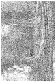
FIG. 10 is an enlarged cross-sectional view showing, in a digital picture,Test Sample 1 of a structure of the first base and a projection of the present invention. -
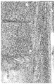
FIG. 11 is an enlarged cross-sectional view showing, in a digital picture,Test Sample 2 of a structure of the first base and a projection of the present invention. -
FIG. 12 is an enlarged cross-sectional view showing, in a digital picture,Test Sample 3 of a structure of the first base and a projection of the present invention.
InFIG. 10 ,FIG. 11 andFIG. 12 , the average thickness of the projection is 0.4 mm, 0.3 mm and 0.2 mm, respectively. -
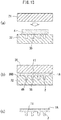
FIG. 13 is a schematic cross-sectional view of another embodiment of a manufacturing method, showing steps of producing a first portion. -
FIG. 14 is a schematic cross-sectional view showing steps of producing a second portion. - In
FIG. 13 andFIG. 14 , areas of the first and second thermoplastic resins are shown in gray in order to make these portions conspicuous. - Preferably, the sole of a shoe further includes at least one second reinforcement fiber F1 buried in the
first base 11. - Thus, it is possible to further reinforce the first base.
- Preferably, at least four layers of reinforcement fiber including the first reinforcement fiber F2 are buried at least in a
corresponding area 11p of thefirst base 11 that corresponds to theprojection 2; and
at least in thecorresponding area 11p, the four layers of reinforcement fiber extend in a direction in which thefirst base 11 extends and are oriented in at least four different directions. - More preferably, many, four to fifty, layers of reinforcement fiber including the first reinforcement fiber F2 are buried at least in a
corresponding area 11p of thefirst base 11 that corresponds to theprojection 2; and
at least in thecorresponding area 11p, the many layers of reinforcement fiber extend in a direction in which thefirst base 11 extends and are oriented in at least four different directions. - In these cases, the four layers of reinforcement fiber oriented in four different directions reinforce the
corresponding area 11p of the first base. This will therefore further increase the strength of the proximal portion of the projection upon which a great bending moment acts. - Depending on the type of the sole, there are various projection shapes and projection arrangements. In contrast, where the four layers of reinforcement fiber arranged in the corresponding
area 11p are oriented in four different directions, the proximal portion will be reinforced with a high reliability even with the various projection shapes and arrangements. - Where the layers of reinforcement fiber are oriented only in one to three directions, there may not be a sufficient reaction force against bending moments in various directions acting upon projections. Also, there may not be a sufficient reaction force against bending moments and torsional moments acting upon the first base.
- In contrast, with the four layers of reinforcement fiber being oriented in four different directions, reaction forces against the aforementioned moments will likely be exerted. Note that with the four layers of reinforcement fiber being oriented in four different directions, quasi-isotropy will likely be exerted. On the other hand, with one to three layers of reinforcement fiber being oriented in one to three directions, it is difficult to exert quasi-isotropy.
- On the other hand, when the number of layers of reinforcement fiber is too large, the first base will be unnecessarily thick. That may detract from the flexibility and the lightweightness needed for the sole. In view of the above, the number of layers of reinforcement fiber is preferably 50 or less.
- The "corresponding area" as used herein means to at least include the projected area obtained as the projection is projected (reflected) in the direction normal to the surface of the sole. The "corresponding area" can be said to mean to at least include the proximal portion of the
projection 2 on thefirst base 11. - Preferably, the sole of a shoe further includes a
second base 12 including, as a main component of thesecond base 12, a second thermoplastic resin that is different from the first thermoplastic resin or including the first thermoplastic resin as a main component of thesecond base 12,
wherein at least asecond base 12 is arranged in anon-corresponding area 12p excluding a correspondingarea 11p corresponding to theprojection 2 and is continuous with thefirst base 11. - The sole is required to have an appropriate rigidity and flexibility depending on each area. In contrast, as the second base including as its main component the second thermoplastic resin is provided in the non-corresponding area, it is likely that the sole has an appropriate rigidity and flexibility depending on each area.
- Now, polyurethane, polyamide, or the like, may be employed, for example, as the second thermoplastic resin.
- The second thermoplastic resin of the second base may be provided other than in the non-corresponding area, and it may be laminated on the corresponding area of the first base and the ground side of the projections, for example. In such a case, the abrasion resistance of the ground side surface may be improved. The foot side of the first base may be laminated on the second base. In such a case, the strength of the sole will be improved.
- Preferably, a length L of the first reinforcement fiber F2 is greater than a height H of the
projection 2. - In such a case, the first reinforcement fiber F2 can be arranged from the proximal portion to the distal portion of the
projection 2, and it will make it easier to reinforce the projection itself. - Preferably, a length L of the first reinforcement fiber F2 is 5 to 60 mm.
- Where the length of the first reinforcement fiber F2 exceeds 60 mm, the fluidity of the first reinforcement fiber F2 when being molded is small even if the matrix resin softens, and the first reinforcement fiber F2 may be unlikely to move into the projections.
- On the other hand, where the length of the first reinforcement fiber F2 is shorter than 5 mm, it is likely that the first reinforcement fiber F2 is not arranged to extend from the first base to the distal portion through the proximal portion. In such a case, it may not be possible to sufficiently increase the bending stiffness of the projection.
- The height of a spike or a cleat is typically between 2 to 3 mm and 10-plus mm. In view of the above, the length of the first reinforcement fiber F2 is more preferably about 10 to 50 mm, and most preferably about 15 to 40 mm.
- On the other hand, while there is no particular limitation on the thickness (diameter) of the first reinforcement fiber F2 and the second reinforcement fiber F1, it is preferably about 3 to 20 µm, more preferably about 4 to 15 µm, and most preferably about 5 to 10 µm.
- Preferably, the average thickness of the
projection 2 is 0.35 mm to 20 mm. - When the average thickness of the projection is smaller than 0.35 mm, the first reinforcement fiber F2 is unlikely to move into the projection, and a sufficient reinforcement is unlikely. On the other hand, when the average thickness of the projection is greater than 20 mm, the projection will in many cases have a sufficient strength without reinforcement with the first reinforcement fiber F2.
- A manufacturing method of the present invention uses a first mold (die) 31 and a
second mold 32 configured to define acavity 30 or aspace 300 therebetween that matches thefirst base 11 and theprojection 2, the method including the steps of: - providing at least one type of
resin plate 4 including the first thermoplastic resin as a main component of theresin plate 4 and having a layered structure including a plurality of layers of reinforcement fiber to be the first reinforcement fiber F2 and/or the second reinforcement fiber F1; - placing the
resin plate 4 on one of the first andsecond molds - heating the at least one type of
resin plate 4; - clamping together the
first mold 31 and thesecond mold 32; and - opening the
first mold 31 and thesecond mold 32 which have been clamped together. - Here, the step of heating the at least one type of
resin plate 4 can be carried out by one of the following approaches (1) to (3), for example: - (1) placing the
resin plate 4 on one of the first andsecond molds resin plate 4 through the one of the molds; - (2) placing the
resin plate 4 on one of the first andsecond molds resin plate 4 by means of a heater, hot air, etc., or heating theresin plate 4 by means of a heater, hot air, etc., and then placing theresin plate 4 on one of the first andsecond molds - (3) a combination of (1) and (2) above.
- With this method, as the resin plate is heated by one or both of the molds and/or a heater, or the like, and the resin plate is pressed and softened by both molds to give the resin plate some fluidity, the resin plate is deformed in conformity with the shape of the cavity, thereby filling the inside of the cavity. Alternatively, the resin plate is squashed in the space between both molds and deformed in conformity with the shape of the molds. At this time, the first thermoplastic resin of the resin plate flows into a concave (depression), which is a cavity or a space, that corresponds to a projection, and some layers of reinforcement fiber move into the concave. Therefore, the layers of reinforcement fiber will be oriented while being bent from the first base toward the projection.
- Preferably, the method includes providing the at least one type of
resin plate 4 including, as a main component of theresin plate 4, the first thermoplastic resin and having, as the layered structure, a layered structure of at least four layers of reinforcement fiber oriented in different directions from each other. - In such a case, four layers of reinforcement fiber that are oriented in different directions from each other will be buried in the first base.
- The
resin plate 4 having a predetermined planar shape and having different layered structures of reinforcement fiber for different areas is provided as the at least one type ofresin plate 4. Note that a preform is preferably used as theresin plate 4. Herein, a preform is a material that is pre-shaped in order to achieve a molded shape with a high precision. - With such a resin plate, since the layered structure of reinforcement fiber varies for different areas, the reaction force of the flow acting upon reinforcement fiber in the molten matrix resin will be small.
- Preferably, the providing step includes providing, as the at least one type of
resin plate 4, aresin plate 4 whose thickness T is 0.5 to 10 mm. - When the thickness of the resin plate is smaller than 0.5 mm, the matrix resin is unlikely to flow across the entirety of the cavity. Particularly, the matrix resin and the reinforcement fiber will be unlikely to flow into the concave corresponding to the projection.
- On the other hand, when the thickness of the
resin plate 4 is greater than 10 mm, the thickness of the sole will be excessive. - In view of the above, the thickness of the
resin plate 4 is more preferably 0.6 to 7.0 mm, and most preferably 1.0 to 5.0 mm. - Preferably, the providing step includes providing the at least one type of
resin plate 4, wherein the number of layers of reinforcement fiber of theresin plate 4 is four to fifty. - In such a case, a first base of a multi-layer structure will likely be obtained.
- Preferably, the providing step includes providing the at least one type of
resin plate 4, wherein a length L of the reinforcement fiber of theresin plate 4 is shorter than one side of theresin plate 4. - In such a case, the length of the reinforcement fiber is shorter than one side of the
resin plate 4. Therefore, the fluidity of the reinforcement fiber will be unlikely to be hindered. Thus, the reinforcement fiber will be likely to flow into the area corresponding to the projection. - Preferably, the step of providing the at least one type of
resin plate 4 includes providing theresin plate 4, wherein a length L of the reinforcement fiber of theresin plate 4 is 5 to 60 mm. - In such a case, the length of the reinforcement fiber is short, and the flow of the reinforcement fiber will be even better.
- Preferably, the method further includes the step of molding (forming) the
second base 12 including the first or second thermoplastic resin as a main component of thesecond base 12. - In such a case, resins and reinforcement fiber can be selectively arranged depending on the area of the sole.
- Preferably, the method includes:
- a first input step of inputting a
thermoplastic resin piece 41 including the reinforcement fiber F to a concave 35 corresponding to theprojection 2 in thecavity 30 or thespace 300; and - a second input step of, after the first input step, inputting the at least one type of
resin plate 4 to an area corresponding to thefirst base 11 in thecavity 30 or thespace 300. - In such a case, a resin piece different from the resin plate is input to the concave. Therefore, it is easy to realize a state where the reinforcement fiber has moved into the projection.
- Preferably, the method further includes the step of heating the
resin piece 41 before or after the first input step and before the second input step. - In such a case, it is possible to use the
resin piece 41 that is longer than the depth of the concave, and the certainty to obtain the second reinforcement fiber will increase significantly. - Any feature illustrated and/or depicted in conjunction with one of the aforementioned aspects or the following embodiments may be used in the same or similar form in one or more of the other aspects or other embodiments, and/or may be used in combination with, or in place of, any feature of the other aspects or embodiments.
- The present invention will be understood more clearly from the following description of preferred embodiments taken in conjunction with the accompanying drawings. Note however that the embodiments and the drawings are merely illustrative and should not be taken to define the scope of the present invention. The scope of the present invention shall be defined only by the appended claims. In the accompanying drawings, like reference numerals denote like components throughout the plurality of figures.
- Embodiments of the present invention will now be described with reference to the drawings.
-
FIG. 1 to FIG. 3B show Embodiment 1 of a spike sole.FIG. 7 andFIG. 8 show an example of a method for manufacturing the spike sole. - The present spike sole shown in
FIG. 1 is a track-and-field spike sole, for example. The spike sole includes a hard sole body including a non-foamed resin component, and many spikes (an example of projections) 2 integrally and seamlessly molded (formed) with the sole body. Note that the sole body is formed from afirst base 11 and asecond base 12. - The present spike sole includes a
first portion 1A and asecond portion 1B. - As shown in
FIG. 1 andFIG. 8(c) , thefirst portion 1A includes thefirst base 11 and theprojections 2, forming a forefoot portion, for example. On the other hand, thesecond portion 1B forms the periphery around thefirst portion 1A, the ground side surface and the rear foot portion. Note that thesecond portion 1B may be laminated on the surface of thefirst portion 1A on the ground side (FIG. 8(c) ) and/or on the foot side (FIG. 14(c) ). - The
first portion 1A and thesecond portion 1B of the present embodiment ofFIG. 1 include, as their main (primary) components, first and second thermoplastic resins, respectively. Thefirst portion 1A includes, as a reinforcement material, the first and/or second reinforcement fiber F2, F1 ofFIG. 3A in the matrix resin including the first thermoplastic resin. - Note that the matrix resin may include another thermoplastic resin other than the first thermoplastic resin.
- As shown in
FIG. 2 , thefirst portion 1A includes thefirst base 11 and theprojections 2. Theprojections 2 project downward (upward inFIG. 2 ) from thefirst base 11 toward the road surface. Theprojections 2 extend seamless and integrally continuous from the surface of thefirst base 11. - As shown in
FIG. 3A and FIG. 3B , the second reinforcement fiber F1 is buried in thefirst base 11. On the other hand, the first reinforcement fiber F2 is provided in thefirst base 11 and theprojection 2 so as to be oriented - while being bent - from thefirst base 11 toward theprojection 2. - Many, four to fifty, layers of the reinforcement fiber F1, F2, including the first reinforcement fiber F2, are buried at least in the
first base 11 ofFIG. 3B including acorresponding area 11p that corresponds to theprojection 2. The many layers of the reinforcement fiber F1, F2 ofFIG. 3A extend in thefirst base 11 including the correspondingarea 11p in the direction in which thefirst base 11 extends, and are oriented in at least four different directions D1 to D4. - Note that
FIG. 3A and FIG. 3B show a single strand of the first reinforcement fiber F2 or the second reinforcement fiber F1 for each layer of reinforcement fiber. For the sake of simplicity of the drawing, of the many strands of the reinforcement fibers F1 and F2, only five strands of the second reinforcement fiber F1 and only four strands of the first reinforcement fiber F2 are shown. - The length L of the first and second reinforcement fibers F2 and F1 of
FIG. 3A may be set to about 20 to 30 mm, for example. The first and second reinforcement fibers F2 and F1 of such a fiber length can be obtained from aresin plate 4 ofFIG. 5 , which includesmany resin pieces 41 ofFIG. 4 aggregated and lying over one another, for example, as will be later described in detail. - The length L of the first reinforcement fiber F2 of
FIG. 3A , which is about 20 to 30 mm, is typically greater than the height H of theprojection 2 ofFIG. 3B . The height H of theprojection 2 means the amount by which it protrudes from the surface of the sole body 5. - The
projections 2 may be spikes or cleats having a tubular shape ofFIG. 2 andFIGS. 6(a) to 6(c), or those having a blade shape, a plate shape or a star shape ofFIGS. 6(d), 6(e) and 6(f) . - In
FIG. 3B , the average thickness of theprojection 2 may be set preferably to about 0.35 to 20 mm. The average thickness is obtained as the average value between the thickness T1 of the distal portion of theprojection 2 and the thickness T2 of the proximal portion thereof. The thickness of theprojection 2 may be tapered from the proximal portion toward the distal portion. Note that with the tubular shape ofFIG. 2 andFIGS. 6(a) to 6(c), the thickness of theprojection 2 means the wall thickness of the tubular portion, for example. - As shown in
FIG. 1 , thesecond portion 1B may be integrally molded (formed) with thefirst portion 1A having such a structure. That is, thesecond base 12 ofFIG. 1 is arranged in anon-corresponding area 12p ofFIG. 1 , excluding the correspondingarea 11p corresponding to theprojection 2 ofFIG. 3B . Thesecond base 12 is continuous with thefirst base 11. Thefirst base 11 and thesecond base 12 cover and support the sole of the foot. - Next, prior to the description of a method for manufacturing the spike sole of
FIG. 1 , theresin plate 4 to be used in the manufacture will be described. - The
resin plate 4 ofFIG. 5 includesmany resin pieces 41 ofFIG. 4 randomly aggregated and lying over one another. That is, eachresin piece 41 is a piece of resin in which a single layer of a plurality of strands of the reinforcement fiber F is oriented, and theresin plate 4 ofFIG. 5 is obtained by primary molding ofsuch resin pieces 41 that are randomly aggregated and lying over one another into a square plate shape, for example. - After the sole is molded, the majority of the reinforcement fiber F of
FIG. 4 becomes the second reinforcement fiber F1 ofFIG. 3A while a portion thereof becomes the first reinforcement fiber F2. - That is, the resin plate 4 (
FIG. 5 ) has a layered structure including a plurality of layers of the reinforcement fiber F ofFIG. 4 to be the first or second reinforcement fiber F2, F1, and the main component thereof is the first thermoplastic resin. As the layered structure, the resin plate 4 (FIG. 5 ) has a layered structure of at least four layers of reinforcement fiber F of different orientation directions D. - The resin plate 4 (
FIG. 5 ) has a predetermined planar shape, and has a layered structure of different reinforcement fibers F for different areas. - Note that the shape of the resin plate 4 (
FIG. 5 ) may be a shape that is approximate to the shape of thefirst portion 1A ofFIG. 1 . - In
FIG. 5 , the thickness T of theresin plate 4 may be 0.5 to 10 mm. The number of layers of the reinforcement fiber F (FIG. 4 ) of theresin plate 4 may be four to fifty. The length L of the reinforcement fiber F ofFIG. 4 of theresin plate 4 is shorter than one side of the resin plate 4 (FIG. 5 ), and may be 5 to 60 mm, for example. - Next, an example of molds (dies) to be used in the present embodiment will be described.
- In the present embodiment, the first to
fourth molds 31 to 34 ofFIG. 7 andFIG. 8 are used as molds. - The first and
second molds FIG. 7 are for molding (forming) thefirst portion 1A. The first andsecond molds cavity 30 that matches thefirst base 11 and theprojections 2. Note that the first andsecond molds cavity 30. - The third and
fourth molds FIG. 8 are for integrally molding (forming) thesecond portion 1B together with thefirst portion 1A. The third andfourth molds cavity 36 that matches thesecond base 12 and anattachment portion 37 of thefirst portion 1A. - As the method for molding the
first portion 1A ofFIG. 7 , a press molding method, for example, is preferred because the matrix resin is likely to move into theprojection 2 and reach the distal portion of theprojection 2. However, a vacuum molding method, a pressure forming method or a vacuum and pressure forming method may be employed. - On the other hand, an injection molding method, for example, may be employed as the method for integrally molding the
second portion 1B ofFIG. 8 together with thefirst portion 1A. - Next, an example of a manufacturing method will be described.
- First, a method for manufacturing the
first portion 1A will be described. - In
FIG. 7(a) , the first andsecond molds resin plate 4 is placed on one of the first andsecond molds - After the placement, the first and
second molds resin plate 4 reach a predetermined temperature, e.g., about 150°C to 300°C. After the temperature of the molds increases to the predetermined temperature, the molds continue to be heated for a predetermined period of time, e.g., 1 second to about 30 minutes. - Thus, the
resin plate 4 softens or melts to a state where it has a sufficient fluidity that allows for molding of theresin plate 4. - Then, as shown in
FIG. 7(b) , thefirst mold 31 and thesecond mold 32 are clamped together so that thefirst mold 31 and thesecond mold 32 meet each other. Theresin plate 4 having melted becomes amolten resin 4M and spreads to fill up thecavity 30 by the clamping, and moves (flows) into portions that correspond to thefirst base 11 and theprojections 2. - Note that the pressure for the clamping may be about 0.1 MPa to 10 MPa, for example.
- Then, while being clamped, the
molds molten resin 4M is cooled and solidified to produce thefirst portion 1A. - After the cooling, the first and
second molds FIG. 7(b) are opened as shown inFIG. 7(c) . After the opening, thefirst portion 1A is taken out of the molds, and burrs (fins), etc., are removed as necessary as well known in the art. - Next, a method for manufacturing the
second portion 1B including thesecond base 12 ofFIG. 8 will be described. - First, as shown in
FIG. 8(a) , thefirst portion 1A is attached to theattachment portion 37 of one of the third andfourth molds - Next, as shown in
FIG. 8(b) , the third andfourth molds molten resin 6M is supplied into thecavity 36 between the third andfourth molds - After the
molten resin 6M solidifies, the third andfourth molds FIG. 8(c) . Then, the molded product is taken out and finished to obtain the spike sole ofFIG. 1 , for example. - Note that the
first portion 1A may be provided not only on a portion of the sole but across the entire length of the sole. Thesecond portion 1B may be absent. A third portion may be provided in addition to thefirst portion 1A and thesecond portion 1B. - Next, another example of the manufacturing method will be described.
- In the present embodiment, the first to
fourth molds 31 to 34 ofFIG. 13 andFIG. 14 are used as molds. - First, a method for manufacturing the
first portion 1A will be described. - In
FIG. 13(a) , the first andsecond molds resin plate 4 is placed on one of the first andsecond molds - After the placement, the first and
second molds resin plate 4 reach a predetermined temperature, e.g., about 150°C to 300°C. After the temperature of the molds increases to the predetermined temperature, the molds continue to be heated for a predetermined period of time, e.g., 1 second to about 30 minutes. - Thus, the
resin plate 4 softens or melts to a state where it has a sufficient fluidity that allows for molding of theresin plate 4. - Then, as shown in
FIG. 13(b) , thefirst mold 31 and thesecond mold 32 are clamped together so that thefirst mold 31 and thesecond mold 32 come close to each other or meet each other. Theresin plate 4 having softened or melted becomes amolten resin 4M and is squashed in aspace 300 between themolds molds first base 11 while the other portions move (flow) into portions that correspond to theprojections 2. - Note that protruding portions to be in contact with the
first mold 31 upon clamping may be provided on the opposite sides of thesecond mold 32, for example. - Note that the pressure for the clamping may be about 0.1 MPa to 10 MPa, for example.
- Then, while being clamped, the
molds molten resin 4M is cooled and solidified to produce thefirst portion 1A. - After the cooling, the first and
second molds FIG. 13(b) are opened. After the opening, thefirst portion 1A ofFIG. 13(c) is taken out of the molds, and burrs, etc., are removed as necessary as well known in the art. - Next, a method for manufacturing the
second portion 1B including thesecond base 12 ofFIG. 14 will be described. - First, as shown in
FIG. 14(a) and FIG. 14(b) , thefirst portion 1A is attached to the attachment portion (cavity) 37 of thethird mold 33 or thefourth mold 34. - Next, another
resin plate 49 or theresin plate 4 is arranged in thecavity 36 between thethird mold 33 and thefourth mold 34. Theother resin plate 49 may be a thermoplastic resin of the same type as or a different type from theresin plate 4, and may include the second reinforcement fiber buried therein. - Then, as shown in
FIG. 14(b) , the third andfourth molds - Before or after the clamping, the third and
fourth molds resin plate resin plate cavity 36 between the third andfourth molds - Then, while being clamped, the
molds resin plate second portion 1B. - After the resin plate is solidified, the third and
fourth molds FIG. 14(b) are opened. Then, the molded product ofFIG. 14(c) is taken out and finished to obtain the spike sole ofFIG. 1 , for example. - Note that the
first portion 1A may be provided not only on a portion of the sole but across the entire length of the sole. Thesecond portion 1B may be absent. A third portion may be provided in addition to thefirst portion 1A and thesecond portion 1B. - Next, an example of an additional manufacturing method will be described with reference to
FIG. 9 . - In the example of
FIG. 9 , theresin piece 41 is used alone, in addition to theresin plate resin piece 41 is formed from a first thermoplastic resin including the reinforcement fiber F. - As shown in
FIG. 9(a) , a first input step is performed by inputting thethermoplastic resin piece 41 including the reinforcement fiber F intoconcaves 35 that correspond to the projections in the cavity 30 (FIG. 7 ) or the space 300 (FIG. 13 ). At this time, theresin piece 41 is input into theconcaves 35 so that a portion of the reinforcement fiber F moves into theconcaves 35 while the rest of the reinforcement fiber F protrudes from the concave 35. - On the other hand, before and after the first input step, a heating step of heating the
resin piece 41 is performed. With this heating, theresin piece 41 softens to be moldable as shown inFIG. 9(b) . - After the first input step and the heating step, a second input step is performed by inputting the
resin plate 4 ofFIG. 9(c) to an area of thecavity 30 ofFIG. 7(a) or the space ofFIG. 13 that corresponds to thefirst base 11. - After the second input step, the steps of
FIGS. 7(a) to 7(c) or the steps ofFIGS. 13(a) to 13(c) are performed, thereby producing thefirst portion 1A. - Next, an example test of the present spike sole will be described.
- By a method similar to the method of
FIG. 7 described above, first to third samples S1 to S3 in which theprojections 2 are integral with thefirst base 11 were obtained as shown inFIGS. 2(a) to 2(c) . Next, these samples were cut along a vertical cross section, and digital pictures of the cross sections were taken, obtaining cross-section pictures as shown inFIG. 10 to FIG. 12 . - In these figures, 11F is the surface of the
first base projection projection 2. - In
FIG. 10 to FIG. 12 , it can be seen that it is possible to perform a molding process such that a matrix resin including the first thermoplastic resin moves into theprojections 2. It can also be seen that the first reinforcement fiber F2, which is a part of the reinforcement fiber, is oriented while being bent from thefirst base 11 toward theprojection 2. - Now, it can be seen that the orientation of the first reinforcement fiber F2 is better in the case of
FIG. 10 (first sample) where the thickness of theprojection 2 is 0.4 mm, as compared with the case ofFIG. 12 where it is 0.2 mm or the case ofFIG. 11 where it is 0.3 mm. Thus, the thickness of theprojection 2 is preferably 0.35 mm or more. - While preferred embodiments have been described above with reference to the drawings, various obvious changes and modifications will readily occur to those skilled in the art upon reading the present specification.
- For example, spikes (projections) may be provided in the rear foot portion, in addition to the forefoot portion.
- Small projections or cleats may be provided instead of spikes.
- Thus, such changes and modifications are deemed to fall within the scope of the present invention.
- The present invention is applicable to track-and-field spike soles and shoe soles, as well as other spike soles and shoe soles for baseball, football, etc.
-
- 1A: First portion, 1B: Second portion
- 11: First base, 11F: Surface, 12: Second base
- 11p: Corresponding area, 12p: Non-corresponding area
- 2: Projection, 2F: Side surface, 2T: Top surface
- 30: Cavity, 31: First mold (die), 32: Second mold (die), 33: Third mold (die), 34: Fourth mold (die), 35: Concave, 36: Cavity, 37: Attachment portion (cavity), 300: Space
- 4: Resin plate, 4M, 6M: Molten resin, 41: Resin piece
- D: Orientation direction, D1 to D4: Four directions
- F: Reinforcement fiber, F1: Second reinforcement fiber, F2: First reinforcement fiber
- H: Height, L: Length, T: Thickness of resin plate, T1, T2: Thickness of projection
- S1 to S3: First to third samples
Claims (19)
- A sole of a shoe comprising:a first base 11 including as its main component a first thermoplastic resin;a projection 2 including as its main component the first thermoplastic resin, the projection 2 projecting from the first base 11; andat least one first reinforcement fiber F2 is provided in the first base 11 and the projection 2 so as to be oriented while being bent from the first base 11 toward the projection 2.
- The sole of a shoe according to claim 1, further comprising at least one second reinforcement fiber F1 buried in the first base 11.
- The sole of a shoe according to claim 1 or 2, wherein:at least four layers of reinforcement fiber including the first reinforcement fiber F2 are buried at least in a corresponding area 11p of the first base 11 that corresponds to the projection 2; andat least in the corresponding area 11p, the four layers of reinforcement fiber extend in a direction in which the first base 11 extends and are oriented in at least four different directions.
- The sole of a shoe according to claim 1 or 2, wherein:many, four to fifty, layers of reinforcement fiber including the first reinforcement fiber F2 are buried at least in a corresponding area 11p of the first base 11 that corresponds to the projection 2; andat least in the corresponding area 11p, the many layers of reinforcement fiber extend in a direction in which the first base 11 extends and are oriented in at least four different directions.
- The sole of a shoe according to claim 1, 2, 3 or 4, further comprising a second base 12 including as its main component a second thermoplastic resin that different from the first thermoplastic resin or including as its main component the first thermoplastic resin,
wherein at least the second base 12 is arranged in a non-corresponding area 12p excluding a corresponding area 11p corresponding to the projection 2 and is continuous with the first base 11. - The sole of a shoe according to any one of claims 1 to 5, wherein a length L of the first reinforcement fiber F2 is greater than a height H of the projection 2.
- The sole of a shoe according to claim 6, wherein a length L of the first reinforcement fiber F2 is 5 to 60 mm.
- The sole of a shoe according to any one of claims 1 to 7, wherein an average thickness of the projection 2 is 0.35 mm to 20 mm.
- The sole of a shoe according to any one of claims 1 to 7, wherein the projection 2 is a tubular, plate-shaped, star-shaped or blade-shaped spike or cleat.
- A method for manufacturing a sole of a shoe according to any one of claims 1 to 9, the method using a first mold 31 and a second mold 32 configured to define a cavity 30 or a space 300 between the first and second molds, the cavity 30 or the space 300 being adapted to the first base 11 and the projection 2, the method comprises the steps of:providing at least one type of resin plate 4 including as its main component the first thermoplastic resin and having a layered structure including a plurality of layers of reinforcement fiber to be the first reinforcement fiber F2 and/or the second reinforcement fiber F1;placing the at least one type of resin plate 4 on one of the first and second molds 31 and 32;heating the at least one type of resin plate 4;clamping together the first mold 31 and the second mold 32; andopening the first mold 31 and the second mold 32 which have been clamped together.
- The method for manufacturing a sole of a shoe according to claim 10, wherein the providing step includes providing the at least one type of resin plate 4 including, as its main component, the first thermoplastic resin and having, as the layered structure, a layered structure of at least four layers of reinforcement fiber oriented in different directions from each other.
- The method for manufacturing a sole of a shoe according to claim 11, wherein the providing step includes providing, as the at least one type of resin plate 4, a resin plate 4 having a predetermined planar shape and having different layered structures of reinforcement fiber for different areas.
- The method for manufacturing a sole of a shoe according to any one of claims 10 to 12, wherein the providing step includes providing, as the at least one type of resin plate 4, a resin plate 4 whose thickness T is 0.5 to 10 mm.
- The method for manufacturing a sole of a shoe according to any one of claims 10 to 13, wherein the providing step includes providing the at least one type of resin plate 4 of which the number of layers of reinforcement fiber is four to fifty.
- The method for manufacturing a sole of a shoe according to any one of claims 10 to 14, wherein the providing step includes providing the at least one type of resin plate 4 of which a length L of the reinforcement fiber is shorter than one side of the resin plate 4.
- The method for manufacturing a sole of a shoe according to any one of claims 10 to 15, wherein the step of providing the at least one type of resin plate 4 includes providing the resin plate 4 of which a length L of the reinforcement fiber is 5 to 60 mm.
- The method for manufacturing a sole of a shoe according to any one of claims 10 to 16, further comprising the step of forming the second base 12 including as its main component the first or second thermoplastic resin.
- The method for manufacturing a sole of a shoe according to any one of claims 10 to 17, comprising:a first input step of inputting a thermoplastic resin piece 41 including the reinforcement fiber F to a concave 35 corresponding to the projection 2 in the cavity 30 or the space 300; anda second input step of, after the first input step, inputting the at least one type of resin plate 4 to an area corresponding to the first base 11 in the cavity 30 or the space 300.
- The method for manufacturing a sole of a shoe according to claim 18, further comprising the step of heating the resin piece 41 before or after the first input step and before the second input step.
Applications Claiming Priority (1)
| Application Number | Priority Date | Filing Date | Title |
|---|---|---|---|
| PCT/JP2016/088491 WO2018116463A1 (en) | 2016-12-22 | 2016-12-22 | Shoe sole and method for manufacturing sole |
Publications (3)
| Publication Number | Publication Date |
|---|---|
| EP3536183A1 true EP3536183A1 (en) | 2019-09-11 |
| EP3536183A4 EP3536183A4 (en) | 2019-12-11 |
| EP3536183B1 EP3536183B1 (en) | 2021-02-03 |
Family
ID=61629116
Family Applications (1)
| Application Number | Title | Priority Date | Filing Date |
|---|---|---|---|
| EP16924292.2A Active EP3536183B1 (en) | 2016-12-22 | 2016-12-22 | Shoe sole and method for manufacturing sole |
Country Status (6)
| Country | Link |
|---|---|
| US (1) | US11864625B2 (en) |
| EP (1) | EP3536183B1 (en) |
| JP (1) | JP6297764B1 (en) |
| CN (1) | CN110121277B (en) |
| AU (1) | AU2016433456B2 (en) |
| WO (1) | WO2018116463A1 (en) |
Cited By (1)
| Publication number | Priority date | Publication date | Assignee | Title |
|---|---|---|---|---|
| TWI934684B (en) | 2025-06-26 | 2026-08-01 | 大陸商宸大增材製造(廈門)有限公司 | Supporting structures for shoe soles and manufacturing method thereof |
Families Citing this family (2)
| Publication number | Priority date | Publication date | Assignee | Title |
|---|---|---|---|---|
| JP7689505B2 (en) * | 2022-03-25 | 2025-06-06 | フクビ化学工業株式会社 | Fiber-reinforced resin molding and its manufacturing method |
| US12569033B2 (en) * | 2023-01-11 | 2026-03-10 | Nike, Inc. | Cushioning structure for article of footwear |
Family Cites Families (11)
| Publication number | Priority date | Publication date | Assignee | Title |
|---|---|---|---|---|
| JPH01254102A (en) * | 1988-04-02 | 1989-10-11 | Asahi Corp | Method of molding antislip shoe sole |
| JP2000102402A (en) | 1998-09-29 | 2000-04-11 | Ryobi Ltd | Spike soles |
| JP3321439B2 (en) * | 1999-09-17 | 2002-09-03 | 日本ピラー工業株式会社 | Tack for soft spike |
| JP2002125709A (en) | 2000-10-25 | 2002-05-08 | Shimano Inc | Fishing shoes |
| FR2824068B1 (en) * | 2001-04-27 | 2005-05-20 | Pascal Tournier | MATERIAL ANTI-SLIP WITH IMPROVED ADHERENCE, PNEUMATIC AND SHOE SOLE INTEGRATING SUCH MATERIAL |
| US8101262B2 (en) * | 2006-09-28 | 2012-01-24 | Toray Industries, Inc. | Fiber-reinforced plastic and process for production thereof |
| EP2687116A4 (en) * | 2011-03-18 | 2015-05-06 | Asics Corp | Reinforcing fiber-reinforced spike sole |
| GB201113575D0 (en) * | 2011-08-05 | 2011-09-21 | Blackett Edward | Footwear and soles for footwear |
| GB201303048D0 (en) * | 2013-02-21 | 2013-04-03 | Wood John | Impact absorbing structure |
| CN106231945B (en) * | 2014-02-25 | 2020-04-17 | 迪亚特克斯株式会社 | Sole, insole, outsole and shoe |
| WO2016162967A1 (en) * | 2015-04-08 | 2016-10-13 | 株式会社アシックス | Spike sole and shoe bottom |
-
2016
- 2016-12-22 EP EP16924292.2A patent/EP3536183B1/en active Active
- 2016-12-22 US US16/468,293 patent/US11864625B2/en active Active
- 2016-12-22 JP JP2017554536A patent/JP6297764B1/en active Active
- 2016-12-22 AU AU2016433456A patent/AU2016433456B2/en active Active
- 2016-12-22 WO PCT/JP2016/088491 patent/WO2018116463A1/en not_active Ceased
- 2016-12-22 CN CN201680091547.4A patent/CN110121277B/en active Active
Cited By (1)
| Publication number | Priority date | Publication date | Assignee | Title |
|---|---|---|---|---|
| TWI934684B (en) | 2025-06-26 | 2026-08-01 | 大陸商宸大增材製造(廈門)有限公司 | Supporting structures for shoe soles and manufacturing method thereof |
Also Published As
| Publication number | Publication date |
|---|---|
| JPWO2018116463A1 (en) | 2018-12-20 |
| CN110121277B (en) | 2021-05-04 |
| AU2016433456B2 (en) | 2020-10-22 |
| US11864625B2 (en) | 2024-01-09 |
| EP3536183B1 (en) | 2021-02-03 |
| EP3536183A4 (en) | 2019-12-11 |
| WO2018116463A1 (en) | 2018-06-28 |
| US20200068990A1 (en) | 2020-03-05 |
| CN110121277A (en) | 2019-08-13 |
| AU2016433456A1 (en) | 2019-07-04 |
| JP6297764B1 (en) | 2018-03-20 |
Similar Documents
| Publication | Publication Date | Title |
|---|---|---|
| US20220274364A1 (en) | Method of manufacturing an article of footwear with a thermoformed siped sole structure | |
| US20040148809A1 (en) | Bicycle shoe sole | |
| KR101843999B1 (en) | Sole plate assembly and method of making | |
| TW201208595A (en) | Cycling footwear structure with a composite sole and a method to realise such structure | |
| EP3745897A1 (en) | Intermediate sole structure with siping | |
| US9283447B1 (en) | Golf club head with composite face | |
| CN105073399B (en) | Wedge, wedged sole structure, mold and molding method for in-molded articles | |
| US20150378350A1 (en) | Method for producing customized insoles | |
| JP2969518B2 (en) | Lightweight core for safety shoes | |
| US11864625B2 (en) | Shoe sole and method for manufacturing sole | |
| KR101864727B1 (en) | Shoes manufacturing method by 3D printing without mold | |
| EP3928969A1 (en) | Footwear sole moulding assembly and manufacturing method for an article of footwear | |
| US20200375312A1 (en) | A sole for a shoe | |
| JP6814123B2 (en) | Shoe sole and sole manufacturing method | |
| EP1809463B1 (en) | Article having an integrated structure of composite material and thermoplastic or elastomer material and process for the production of the said article | |
| US20230088134A1 (en) | Outsole formed from sheet molding compound | |
| CN104470391A (en) | Safety Boots with Protective Layers | |
| US20260076444A1 (en) | Sole for article of footwear having detachable traction elements and method of manufacturing thereof | |
| KR20040010799A (en) | sole of bicycle rider's shoes and manufacturing method | |
| CN121220851A (en) | A shoe sole component based on breathable metal processing and its manufacturing method, shoe sole and shoe | |
| AU4615801A (en) | Protective footwear reinforcement and method of manufacture thereof | |
| FR2763016A1 (en) | Protective toe caps |
Legal Events
| Date | Code | Title | Description |
|---|---|---|---|
| STAA | Information on the status of an ep patent application or granted ep patent |
Free format text: STATUS: THE INTERNATIONAL PUBLICATION HAS BEEN MADE |
|
| PUAI | Public reference made under article 153(3) epc to a published international application that has entered the european phase |
Free format text: ORIGINAL CODE: 0009012 |
|
| STAA | Information on the status of an ep patent application or granted ep patent |
Free format text: STATUS: REQUEST FOR EXAMINATION WAS MADE |
|
| 17P | Request for examination filed |
Effective date: 20190607 |
|
| AK | Designated contracting states |
Kind code of ref document: A1 Designated state(s): AL AT BE BG CH CY CZ DE DK EE ES FI FR GB GR HR HU IE IS IT LI LT LU LV MC MK MT NL NO PL PT RO RS SE SI SK SM TR |
|
| AX | Request for extension of the european patent |
Extension state: BA ME |
|
| A4 | Supplementary search report drawn up and despatched |
Effective date: 20191111 |
|
| RIC1 | Information provided on ipc code assigned before grant |
Ipc: A43B 5/00 20060101ALI20191105BHEP Ipc: A43C 15/02 20060101ALI20191105BHEP Ipc: A43B 13/02 20060101ALI20191105BHEP Ipc: A43B 13/26 20060101AFI20191105BHEP |
|
| DAV | Request for validation of the european patent (deleted) | ||
| DAX | Request for extension of the european patent (deleted) | ||
| GRAP | Despatch of communication of intention to grant a patent |
Free format text: ORIGINAL CODE: EPIDOSNIGR1 |
|
| STAA | Information on the status of an ep patent application or granted ep patent |
Free format text: STATUS: GRANT OF PATENT IS INTENDED |
|
| INTG | Intention to grant announced |
Effective date: 20200804 |
|
| GRAS | Grant fee paid |
Free format text: ORIGINAL CODE: EPIDOSNIGR3 |
|
| GRAA | (expected) grant |
Free format text: ORIGINAL CODE: 0009210 |
|
| STAA | Information on the status of an ep patent application or granted ep patent |
Free format text: STATUS: THE PATENT HAS BEEN GRANTED |
|
| AK | Designated contracting states |
Kind code of ref document: B1 Designated state(s): AL AT BE BG CH CY CZ DE DK EE ES FI FR GB GR HR HU IE IS IT LI LT LU LV MC MK MT NL NO PL PT RO RS SE SI SK SM TR |
|
| REG | Reference to a national code |
Ref country code: GB Ref legal event code: FG4D |
|
| REG | Reference to a national code |
Ref country code: AT Ref legal event code: REF Ref document number: 1359521 Country of ref document: AT Kind code of ref document: T Effective date: 20210215 Ref country code: CH Ref legal event code: EP |
|
| REG | Reference to a national code |
Ref country code: DE Ref legal event code: R096 Ref document number: 602016052411 Country of ref document: DE |
|
| REG | Reference to a national code |
Ref country code: IE Ref legal event code: FG4D |
|
| REG | Reference to a national code |
Ref country code: NL Ref legal event code: MP Effective date: 20210203 |
|
| REG | Reference to a national code |
Ref country code: LT Ref legal event code: MG9D |
|
| REG | Reference to a national code |
Ref country code: AT Ref legal event code: MK05 Ref document number: 1359521 Country of ref document: AT Kind code of ref document: T Effective date: 20210203 |
|
| PG25 | Lapsed in a contracting state [announced via postgrant information from national office to epo] |
Ref country code: BG Free format text: LAPSE BECAUSE OF FAILURE TO SUBMIT A TRANSLATION OF THE DESCRIPTION OR TO PAY THE FEE WITHIN THE PRESCRIBED TIME-LIMIT Effective date: 20210503 Ref country code: LT Free format text: LAPSE BECAUSE OF FAILURE TO SUBMIT A TRANSLATION OF THE DESCRIPTION OR TO PAY THE FEE WITHIN THE PRESCRIBED TIME-LIMIT Effective date: 20210203 Ref country code: HR Free format text: LAPSE BECAUSE OF FAILURE TO SUBMIT A TRANSLATION OF THE DESCRIPTION OR TO PAY THE FEE WITHIN THE PRESCRIBED TIME-LIMIT Effective date: 20210203 Ref country code: GR Free format text: LAPSE BECAUSE OF FAILURE TO SUBMIT A TRANSLATION OF THE DESCRIPTION OR TO PAY THE FEE WITHIN THE PRESCRIBED TIME-LIMIT Effective date: 20210504 Ref country code: FI Free format text: LAPSE BECAUSE OF FAILURE TO SUBMIT A TRANSLATION OF THE DESCRIPTION OR TO PAY THE FEE WITHIN THE PRESCRIBED TIME-LIMIT Effective date: 20210203 Ref country code: PT Free format text: LAPSE BECAUSE OF FAILURE TO SUBMIT A TRANSLATION OF THE DESCRIPTION OR TO PAY THE FEE WITHIN THE PRESCRIBED TIME-LIMIT Effective date: 20210604 Ref country code: NO Free format text: LAPSE BECAUSE OF FAILURE TO SUBMIT A TRANSLATION OF THE DESCRIPTION OR TO PAY THE FEE WITHIN THE PRESCRIBED TIME-LIMIT Effective date: 20210503 |
|
| PG25 | Lapsed in a contracting state [announced via postgrant information from national office to epo] |
Ref country code: AT Free format text: LAPSE BECAUSE OF FAILURE TO SUBMIT A TRANSLATION OF THE DESCRIPTION OR TO PAY THE FEE WITHIN THE PRESCRIBED TIME-LIMIT Effective date: 20210203 Ref country code: LV Free format text: LAPSE BECAUSE OF FAILURE TO SUBMIT A TRANSLATION OF THE DESCRIPTION OR TO PAY THE FEE WITHIN THE PRESCRIBED TIME-LIMIT Effective date: 20210203 Ref country code: RS Free format text: LAPSE BECAUSE OF FAILURE TO SUBMIT A TRANSLATION OF THE DESCRIPTION OR TO PAY THE FEE WITHIN THE PRESCRIBED TIME-LIMIT Effective date: 20210203 Ref country code: PL Free format text: LAPSE BECAUSE OF FAILURE TO SUBMIT A TRANSLATION OF THE DESCRIPTION OR TO PAY THE FEE WITHIN THE PRESCRIBED TIME-LIMIT Effective date: 20210203 Ref country code: NL Free format text: LAPSE BECAUSE OF FAILURE TO SUBMIT A TRANSLATION OF THE DESCRIPTION OR TO PAY THE FEE WITHIN THE PRESCRIBED TIME-LIMIT Effective date: 20210203 Ref country code: SE Free format text: LAPSE BECAUSE OF FAILURE TO SUBMIT A TRANSLATION OF THE DESCRIPTION OR TO PAY THE FEE WITHIN THE PRESCRIBED TIME-LIMIT Effective date: 20210203 |
|
| PG25 | Lapsed in a contracting state [announced via postgrant information from national office to epo] |
Ref country code: IS Free format text: LAPSE BECAUSE OF FAILURE TO SUBMIT A TRANSLATION OF THE DESCRIPTION OR TO PAY THE FEE WITHIN THE PRESCRIBED TIME-LIMIT Effective date: 20210603 |
|
| PG25 | Lapsed in a contracting state [announced via postgrant information from national office to epo] |
Ref country code: SM Free format text: LAPSE BECAUSE OF FAILURE TO SUBMIT A TRANSLATION OF THE DESCRIPTION OR TO PAY THE FEE WITHIN THE PRESCRIBED TIME-LIMIT Effective date: 20210203 Ref country code: EE Free format text: LAPSE BECAUSE OF FAILURE TO SUBMIT A TRANSLATION OF THE DESCRIPTION OR TO PAY THE FEE WITHIN THE PRESCRIBED TIME-LIMIT Effective date: 20210203 Ref country code: CZ Free format text: LAPSE BECAUSE OF FAILURE TO SUBMIT A TRANSLATION OF THE DESCRIPTION OR TO PAY THE FEE WITHIN THE PRESCRIBED TIME-LIMIT Effective date: 20210203 |
|
| REG | Reference to a national code |
Ref country code: DE Ref legal event code: R097 Ref document number: 602016052411 Country of ref document: DE |
|
| PG25 | Lapsed in a contracting state [announced via postgrant information from national office to epo] |
Ref country code: DK Free format text: LAPSE BECAUSE OF FAILURE TO SUBMIT A TRANSLATION OF THE DESCRIPTION OR TO PAY THE FEE WITHIN THE PRESCRIBED TIME-LIMIT Effective date: 20210203 Ref country code: RO Free format text: LAPSE BECAUSE OF FAILURE TO SUBMIT A TRANSLATION OF THE DESCRIPTION OR TO PAY THE FEE WITHIN THE PRESCRIBED TIME-LIMIT Effective date: 20210203 Ref country code: SK Free format text: LAPSE BECAUSE OF FAILURE TO SUBMIT A TRANSLATION OF THE DESCRIPTION OR TO PAY THE FEE WITHIN THE PRESCRIBED TIME-LIMIT Effective date: 20210203 |
|
| PLBE | No opposition filed within time limit |
Free format text: ORIGINAL CODE: 0009261 |
|
| STAA | Information on the status of an ep patent application or granted ep patent |
Free format text: STATUS: NO OPPOSITION FILED WITHIN TIME LIMIT |
|
| 26N | No opposition filed |
Effective date: 20211104 |
|
| PG25 | Lapsed in a contracting state [announced via postgrant information from national office to epo] |
Ref country code: ES Free format text: LAPSE BECAUSE OF FAILURE TO SUBMIT A TRANSLATION OF THE DESCRIPTION OR TO PAY THE FEE WITHIN THE PRESCRIBED TIME-LIMIT Effective date: 20210203 Ref country code: AL Free format text: LAPSE BECAUSE OF FAILURE TO SUBMIT A TRANSLATION OF THE DESCRIPTION OR TO PAY THE FEE WITHIN THE PRESCRIBED TIME-LIMIT Effective date: 20210203 |
|
| PG25 | Lapsed in a contracting state [announced via postgrant information from national office to epo] |
Ref country code: SI Free format text: LAPSE BECAUSE OF FAILURE TO SUBMIT A TRANSLATION OF THE DESCRIPTION OR TO PAY THE FEE WITHIN THE PRESCRIBED TIME-LIMIT Effective date: 20210203 |
|
| PG25 | Lapsed in a contracting state [announced via postgrant information from national office to epo] |
Ref country code: IT Free format text: LAPSE BECAUSE OF FAILURE TO SUBMIT A TRANSLATION OF THE DESCRIPTION OR TO PAY THE FEE WITHIN THE PRESCRIBED TIME-LIMIT Effective date: 20210203 |
|
| PG25 | Lapsed in a contracting state [announced via postgrant information from national office to epo] |
Ref country code: IS Free format text: LAPSE BECAUSE OF FAILURE TO SUBMIT A TRANSLATION OF THE DESCRIPTION OR TO PAY THE FEE WITHIN THE PRESCRIBED TIME-LIMIT Effective date: 20210603 |
|
| PG25 | Lapsed in a contracting state [announced via postgrant information from national office to epo] |
Ref country code: MC Free format text: LAPSE BECAUSE OF FAILURE TO SUBMIT A TRANSLATION OF THE DESCRIPTION OR TO PAY THE FEE WITHIN THE PRESCRIBED TIME-LIMIT Effective date: 20210203 |
|
| REG | Reference to a national code |
Ref country code: CH Ref legal event code: PL |
|
| REG | Reference to a national code |
Ref country code: BE Ref legal event code: MM Effective date: 20211231 |
|
| PG25 | Lapsed in a contracting state [announced via postgrant information from national office to epo] |
Ref country code: LU Free format text: LAPSE BECAUSE OF NON-PAYMENT OF DUE FEES Effective date: 20211222 Ref country code: IE Free format text: LAPSE BECAUSE OF NON-PAYMENT OF DUE FEES Effective date: 20211222 |
|
| PG25 | Lapsed in a contracting state [announced via postgrant information from national office to epo] |
Ref country code: BE Free format text: LAPSE BECAUSE OF NON-PAYMENT OF DUE FEES Effective date: 20211231 |
|
| PG25 | Lapsed in a contracting state [announced via postgrant information from national office to epo] |
Ref country code: LI Free format text: LAPSE BECAUSE OF NON-PAYMENT OF DUE FEES Effective date: 20211231 Ref country code: CH Free format text: LAPSE BECAUSE OF NON-PAYMENT OF DUE FEES Effective date: 20211231 |
|
| PG25 | Lapsed in a contracting state [announced via postgrant information from national office to epo] |
Ref country code: CY Free format text: LAPSE BECAUSE OF FAILURE TO SUBMIT A TRANSLATION OF THE DESCRIPTION OR TO PAY THE FEE WITHIN THE PRESCRIBED TIME-LIMIT Effective date: 20210203 |
|
| PG25 | Lapsed in a contracting state [announced via postgrant information from national office to epo] |
Ref country code: HU Free format text: LAPSE BECAUSE OF FAILURE TO SUBMIT A TRANSLATION OF THE DESCRIPTION OR TO PAY THE FEE WITHIN THE PRESCRIBED TIME-LIMIT; INVALID AB INITIO Effective date: 20161222 |
|
| PG25 | Lapsed in a contracting state [announced via postgrant information from national office to epo] |
Ref country code: MK Free format text: LAPSE BECAUSE OF FAILURE TO SUBMIT A TRANSLATION OF THE DESCRIPTION OR TO PAY THE FEE WITHIN THE PRESCRIBED TIME-LIMIT Effective date: 20210203 |
|
| PG25 | Lapsed in a contracting state [announced via postgrant information from national office to epo] |
Ref country code: MT Free format text: LAPSE BECAUSE OF FAILURE TO SUBMIT A TRANSLATION OF THE DESCRIPTION OR TO PAY THE FEE WITHIN THE PRESCRIBED TIME-LIMIT Effective date: 20210203 |
|
| PG25 | Lapsed in a contracting state [announced via postgrant information from national office to epo] |
Ref country code: TR Free format text: LAPSE BECAUSE OF FAILURE TO SUBMIT A TRANSLATION OF THE DESCRIPTION OR TO PAY THE FEE WITHIN THE PRESCRIBED TIME-LIMIT Effective date: 20210203 |
|
| PGFP | Annual fee paid to national office [announced via postgrant information from national office to epo] |
Ref country code: DE Payment date: 20251028 Year of fee payment: 10 |
|
| PGFP | Annual fee paid to national office [announced via postgrant information from national office to epo] |
Ref country code: GB Payment date: 20251030 Year of fee payment: 10 |
|
| PGFP | Annual fee paid to national office [announced via postgrant information from national office to epo] |
Ref country code: FR Payment date: 20251110 Year of fee payment: 10 |