EP3536074B1 - Trägeraggregation auf kombiniertem benutzergerät - Google Patents
Trägeraggregation auf kombiniertem benutzergerät Download PDFInfo
- Publication number
- EP3536074B1 EP3536074B1 EP17784475.0A EP17784475A EP3536074B1 EP 3536074 B1 EP3536074 B1 EP 3536074B1 EP 17784475 A EP17784475 A EP 17784475A EP 3536074 B1 EP3536074 B1 EP 3536074B1
- Authority
- EP
- European Patent Office
- Prior art keywords
- data
- base station
- primary
- combined
- target
- Prior art date
- Legal status (The legal status is an assumption and is not a legal conclusion. Google has not performed a legal analysis and makes no representation as to the accuracy of the status listed.)
- Active
Links
Images






Classifications
-
- H—ELECTRICITY
- H04—ELECTRIC COMMUNICATION TECHNIQUE
- H04W—WIRELESS COMMUNICATION NETWORKS
- H04W72/00—Local resource management
- H04W72/04—Wireless resource allocation
- H04W72/044—Wireless resource allocation based on the type of the allocated resource
- H04W72/0453—Resources in frequency domain, e.g. a carrier in FDMA
-
- H—ELECTRICITY
- H04—ELECTRIC COMMUNICATION TECHNIQUE
- H04W—WIRELESS COMMUNICATION NETWORKS
- H04W72/00—Local resource management
- H04W72/50—Allocation or scheduling criteria for wireless resources
- H04W72/51—Allocation or scheduling criteria for wireless resources based on terminal or device properties
Definitions
- This disclosure relates to carrier aggregation on a combined user equipment.
- LTE Long-Term Evolution
- GSM/EDGE Global System for Mobile Communications/Enhanced Data Rates for GSM Evolution
- UMTS/HSPA Universal Mobile Telecommunication System/High Speed Packet Access
- LTE is configured to increase the capacity and speed of the telecommunication by using different ratio interfaces in addition to core network improvements.
- LTE supports scalable carrier bandwidths, from 1.4 MHz to 20MHz and supports both frequency division duplexing (FDD) and time-division duplexing (TDD).
- FDD frequency division duplexing
- TDD time-division duplexing
- a wireless User Equipment can be allocated a traffic channel and a signaling channel by an evolved Node B (eNB) for exchanging signaling and communications with the eNB.
- eNB evolved Node B
- Carrier aggregation allows the eNB to allocate multiple carriers (e.g., mobile operators) jointly for use by the UE in exchanging higher rate communications with the eNB.
- Each aggregated carrier is referred to as a component carrier (CC).
- Carrier aggregation generally defines a number of servicing cells, one for each component carrier. The coverage of the serving cells may differ.
- a Primary Serving Cell may serve a Primary CC (PCC) for handling Radio Resource Control (RRC) connection between the UE and the eNB, while at least one Secondary Servicing Cell (SCC) associated with at least one Secondary CC (SCC) may be added for providing additional bandwidth.
- PSC Primary Serving Cell
- PCC Primary CC
- RRC Radio Resource Control
- SCC Secondary Servicing Cell
- SCC Secondary CC
- Document WO 2016/022214 A1 refers to a user equipment (UE) that is configured to perform cell selection and camp on a first cell in a first frequency resource.
- the UE is configured to determine that proximity services are supported in a second frequency resource.
- the first and second wireless frequency resources are within licensed spectrums corresponding to one or more mobile communications networks.
- the UE is configured to start device-to-device communication on the second frequency resource and send, with the transceiver, a device-to-device message in the second frequency resource.
- the device-to-device message includes one of a device-to-device discovery message and a device-to-device communication message.
- Document WO 2014/145102 A1 refers to a wireless communication system for future scheduling of secondary component carrier(s) (SCC) during carrier aggregation in LTE wireless communications.
- SCC secondary component carrier
- a primary component carrier in a first subframe can be used to indicate at what future subframe see data may exist for the mobile device (e.g., US, etc.).
- the UE can then leave off all SCC receive circuitry until the future subframe, when it can turn on all needed see receive circuitry to receive the see data. After receiving the SCC data, the UE can again power off the SCC receive circuitry.
- Document US 2012/322175 A1 refers to a carrier configuration method for a multi-carrier communication system having a base station (BS) and a terminal.
- the BS divides multiple component carriers (CCs) of the terminal to multiple CC groups, wherein the CCs using at least one identical configuration parameter are divided into the same CC group.
- the BS transmits a CC configuration message comprising at least one configuration parameter data to the terminal, wherein the configuration message comprises or does not comprise at least one CC configuration indicator.
- the terminal will receive the CC configuration message, and configure the configuration parameter of the configurations of the CCs indicated by the CC configuration indicator according to the configuration parameter data; otherwise, the terminal will configure the configuration parameter of the configurations of the default CCs (e.g. all of the CCs currently used by the terminal, or primary CCs).
- the default CCs e.g. all of the CCs currently used by the terminal, or primary CCs.
- Document WO 2015/170392 A1 refers to a terminal that detects another terminal that can directly communicate wirelessly with the terminal in a first band using a first detection signal of the first band, sends a second detection signal of a second band addressed to the detected other terminal and makes a determination as to whether direct wireless communications with the other terminal are possible in the second band, and, on the basis of the determination results, directly communicates wirelessly with the other terminal in at least one of the first band and the second band.
- One aspect of the disclosure provides a method for instructing at least one secondary UE to operate on at least one secondary CC and receive data from a network base station on the at least one secondary CC.
- the method includes receiving, at data processing hardware of a primary UE, a connection request from a network base station on a primary CC associated with the primary UE.
- the method also includes connecting, by the data processing hardware, to the network base station on the primary CC and receiving, at the data processing hardware, a configuration message from the network base station.
- the configuration message instructs operation of the at least one secondary CC, the at least one secondary CC associated with at least one secondary UE.
- the method includes instructing, by the data processing hardware, the at least one secondary UE to operate on the at least one secondary CC and receive data from the network base station on the at least one secondary CC.
- Implementations of the disclosure may include one or more of the following optional features.
- the method in response to receiving the configuration message, includes instructing, by the data processing hardware, the at least one secondary UE operating on the at least one secondary CC to send the received data from the network base station to a target device.
- the target device may include at least one of another base station or another UE.
- the method includes advertising, by the data processing hardware, a carrier aggregation capability of a combined UE including the primary UE and the at least one secondary UE.
- the combined UE may be recognized by the network base station as a single UE associated with the primary CC and the at least one secondary CC.
- the method may include receiving the connection request, the connection request for communicating on one of the primary CC or the at least one secondary CC.
- Instructing the at least one secondary CC to operate may include enabling a combined-UE operating state of the at least one secondary UE.
- the combined-UE operating state may allow cross-carrier aggregation of a combined UE including the primary UE and the at least one secondary UE.
- the combined UE may be recognized by the network base station as a single UE associated with the primary CC and the at least one secondary CC.
- the at least one secondary UE may include a plurality of secondary UEs, and the configuration message may instruct enabling a target secondary UE associated with a target secondary CC to receive the data from the network base station.
- the method may include scheduling transmission of data from the network base station to the target secondary UE.
- the method may also include transmission of the data from the target secondary UE to a target device.
- the at least one secondary CC may include a plurality of secondary CCs
- the configuration message may instruct enabling a target secondary UE to operate on a first target secondary CC to receive the data from the network base station and to operate on a second target secondary CC to receive data from another base station.
- the at least one secondary UE may include a plurality of secondary UEs and the at least one secondary CC may include a plurality of secondary CCs.
- the configuration message may further instruct enabling a first target secondary UE associated with a first target secondary CC to receive the data from the base station and may instruct enabling a second target secondary UE associated with a second target secondary CC to receive data from the network base station.
- the system includes a network base station and a plurality of UEs including a primary UE and secondary UEs. Each UE is associated with at least one CC.
- the primary UE is configured to perform operations. The operations include receiving a connection request from the network base station on a primary CC associated with the primary UE and connecting to the network base station on the primary CC.
- the operations also include receiving a configuration message from the network base station, the configuration message instructing operation of at least one secondary CC, the at least one secondary CC associated with at least one secondary UE.
- the operations include instructing the at least one secondary UE to operate on the at least one secondary CC and receive data from the network base station on the at least one secondary CC.
- the operations include, in response to receiving the configuration message, instructing the at least one secondary UE operating on the at least one secondary CC to send the received data from the network base station to a target device.
- the target device may include at least one of another base station or another UE.
- the operations may also include advertising a carrier aggregation capability of a combined UE including the primary UE and the at least one secondary UE.
- the combined UE may recognize by the network base station as a single UE associated with the primary CC and the at least one secondary CC.
- the operations may include receiving the connection request, the connection request for communicating on one of the primary CC or the at least one secondary CC.
- the operations include instructing the at least one secondary CC to operate including enabling a combined-UE operating state of the at least one secondary UE.
- the combined-UE operating state may allow cross-carrier aggregation of a combined UE including the primary UE and the at least one secondary UE, the combined UE recognized by the network base station as a single UE associated with the primary CC and the at least one secondary CC.
- the at least one secondary UE may include a plurality of secondary UEs, and the configuration message may instruct enabling a target secondary UE associated with a target secondary CC to receive the data from the network base station.
- the operations may include scheduling transmission of data from the network base station to the target secondary UE.
- the target secondary UE may transmit the data from the network base station to a target device.
- the at least one secondary CC may include a plurality of secondary CCs.
- the configuration message may instruct enabling a target secondary UE to operate on a first target secondary CC to receive the data from the base station and to operate on a second target category CC to receive data from another base station.
- the at least one secondary UE may include a plurality of secondary UEs and the at least one secondary CC may include a plurality of secondary CCs.
- the configuration message may instruct enabling a first target secondary UE associated with a first target secondary CC to receive the data from the base station and instruct enabling a second target secondary UE associated with a second target secondary CC to receive data from the base station.
- Yet another aspect of the disclosure provides a method for routing a communication of data from a network base station through a combined UE to the destination.
- the method includes receiving, at data processing hardware, a communication request from a network base station for delivery of data to a destination and routing, by the data processing hardware, the communication of data from the network base station through the combined UE to the destination.
- the combined UE may include slave UEs, each slave UE in communication with the data processing hardware and having an associated CC, the combined UE recognized by the network base station as a single UE associated with the CCs of the slave UEs.
- the routing includes identifying at least one target slave UE for routing the communication of data based on the CC associated with the at least one target slave UE and scheduling the routing of the communication of data through the identified at least one target slave UE.
- the routing includes identifying multiple target slave UEs for routing the communication of data and scheduling concurrent routing of the communication of data through the identified multiple target slave UEs.
- the CC associated with each slave UE may be different from each other CC associated with each other slave UE.
- Each slave UE may include an associated network identity that is different from each other network identity associated with each other slave UE.
- the method may further include providing, by the data processing hardware, the network identity associated with each slave UE to the network base station.
- the system includes a network base station, the combined UE including slave UEs, and a network device in communication with the network base station and the slave UEs.
- Each slave UE has an associated CC.
- the combined UE may be recognized by the network base station as a single UE associated with the CCs of the slave UEs.
- the network base station may be configured to perform operations. The operations include receiving a communication request from the network base station for delivery of data to a destination and routing the communication of data from the network base station through the combined UE to the destination.
- the routing includes identifying at least one target slave UE for routing the communication of data based on the CC associated with the at least one target slave UE and scheduling the routing of the communication of data through the identified at least one target slave UE.
- the routing includes identifying multiple target slave UEs for routing the communication of data and scheduling concurrent routing of the communication of data through the identified multiple target slave UEs.
- the CC associated with each slave UE may be different from each other CC associated with each other slave UE.
- Each slave UE may include an associated network identity that is different from each other network identity associated with each other slave UE.
- the system may also include providing, by the data processing hardware, the network identity associated with each slave UE to the network base station.
- Mobile wireless network subscribers typically use mobile terminals (e.g., mobile phones) having high-volume and inexpensive mobile chipsets. These inexpensive mobile chipsets restrict the mobile phones to lower data rate plans peaking at 100 Megabits per second (Mbps). While wireless spectrum within bands ranging from about 80 Megahertz (MHz) to about 100 MHz may allow service providers to offer higher data rate plans (e.g., greater than 500 Mbps), the inexpensive mobile chipsets prevent the mobile terminals for achieving the high data rates. For instance, available network base stations may support up to five component carriers that may be aggregated to communicate data to and from mobile terminals within a service area of the network base station.
- the mobile terminals currently only support one or two downlink component carriers, and are only expected to support up to three downlink component carriers in the following years. As a result, the mobile terminals are lagging behind the performance capabilities of the network base stations.
- Implementations herein are directed toward combining multiple mobile terminals into a combined terminal that is recognized by network base stations as a single device.
- the combined terminal leverages at least one component carrier from each of the multiple mobile terminals to provide carrier aggregation capabilities in line with the carrier aggregation capabilities of the network base stations.
- the combined terminals allows five or more component carriers to be aggregated, and therefore improves a threshold efficiency of the wireless spectrum.
- FIG. 1 shows a Long-Term Evolution (LTE) network 100.
- LTE is a standard for wireless communication of high-speed data between multiple base stations 102, 102an and User Equipment (UE) 104, 104a-n, such as mobile phones and data terminals.
- UE User Equipment
- LTE is based on the Global System for Mobile Communications/Enhanced Data Rates for GSM Evolution (GSM/EDGE) and Universal Mobile Telecommunication System/High Speed Packet Access (UMTS/HSPA) network technologies.
- GSM/EDGE Global System for Mobile Communications/Enhanced Data Rates for GSM Evolution
- UMTS/HSPA Universal Mobile Telecommunication System/High Speed Packet Access
- LTE is configured to increase the capacity and speed of the telecommunication by using different radio interfaces in addition to core network improvements.
- LTE supports scalable carrier bandwidths, from 1.4 MHz to 20MHz and supports both frequency division duplexing (FDD) and time-division duplexing (TDD).
- FDD frequency division duplexing
- TDD
- LTE-TDD networks 100 use a single frequency for uploading and downloading information.
- LTE-TDD networks 100 operate at frequencies ranging from 1450 MHz to 4300 MHz, with several different bands being used.
- LTE-FDD networks 100 refer to the transmitting device (e.g., base station 102 and the UE 104 transmitting and/or receiving upon different carrier frequencies.
- an Evolved Packet Core (EPC) 106 provides a framework configured to converge voice and data on the LTE network 100.
- the EPC 106 unifies voice and data on an Internet Protocol (IP) service architecture and voice is treated as just another IP application.
- IP Internet Protocol
- the EPC 106 includes several key components 108 that include, without limitations, a Mobility Management Entity (MME), a Serving Gateway (SGW), and a Packet Data Node Gateway (PGW).
- MME Mobility Management Entity
- SGW Serving Gateway
- PGW Packet Data Node Gateway
- the MME is a key control-code for the LTE network 100.
- the MME manages session and states and authenticates and tracks a UE 104 across the network 100.
- the SGW is responsible for routing packets through the network 100.
- the PGW is an interface between the LTE network 100 and other packet data networks, manages quality of service (QoS), and provides deep packet inspection (DPI).
- QoS quality of service
- DPI deep packet inspection
- Each base station 102 may include an evolved Node B (also referred as eNode B or eNB).
- An eNB 102 includes hardware that connects to an air interface 110 (e.g., a mobile phone network) for communicating directly with the UEs 104. For instance, the eNB 102 may transmit downlink LTE signals (e.g., communications) to the UEs 104 and receive uplink LTE signals from the UEs 104 over the air interface 110.
- the eNB 102 does not have a separate controller element and, thus, simplifies the architecture of the network 100.
- the eNB 102 embeds its own control functionality, since the eNB 102 does not include a separate controller element.
- the eNB 102 uses multiple protocols when interfacing with different elements.
- the eNB 102 uses an X2-interface 112 when communicating with other eNBs 102 in the network 100 and uses an S1 interface 114 for communicating with the EPC 106.
- the S1 interface 114 may include an S1-MME interface for communicating with the MME and an S1-U interface for interfacing with the SGW. Accordingly, the S1 interface 114 is associated with a backhaul link for communicating with the EPC 106.
- UEs 104 may be any telecommunication device that is capable of transmitting and/or receiving voice/data over the network 100.
- UEs 104 may include, but are not limited to, mobile computing devices, such as laptops, tablets, smart phones, and wearable computing devices (e.g., headsets and/or watches).
- UEs 104 may also include other computing devices having other form factors, such as computing devices included in desktop computers, vehicles, gaming devices, televisions, or other appliances (e.g., networked home automation devices and home appliances).
- the network 100 supports carrier aggregation where multiple component carriers (CCs) 220 ( FIGS. 2A and 2B ) are aggregated and jointly used for transmission to/from a single device (e.g., UE 104).
- the network 100 may include an LTE-Advanced network under Release 10 (LTE Rel-10) providing higher bitrates while still fulfilling requirements set by existing 4G networks.
- LTE Rel-10 LTE-Advanced network under Release 10
- a CC 220 may have a bandwidth of 1.4, 3, 5, 10 or 20 Megahertz (MHz) and a maximum of five CCs 220 may be aggregated to provide a maximum aggregated bandwidth equal to 100 MHz.
- LTE Release 13 LTE Rel-13
- Future releases, such as LTE Release 13 (LTE Rel-13) may support up to a maximum of thirty-two (32) CCs 220.
- the number of aggregated carriers may be different for downlink (DL) communications and uplink (UL) communications.
- the number of UL CCs 220 is always equal to or less than the number of DL CCs 220 and individual CCs 220 can also be of different bandwidths.
- the number of CCs 220 as well as the bandwidths of each CC 220 are normally the same for DL and UL communications.
- intra-band contiguous carrier aggregation The easiest way to arrange aggregation is through contiguous CCs with the same frequency band, referred to as intra-band contiguous carrier aggregation.
- intra-band continuous carrier aggregation may not always be possible.
- non-contiguous allocation may be arranged for one of intra-band or inter-band.
- intra-band non-continuous the aggregated CCs 220 belong to the same frequency band, but include a gap or gaps in between.
- inter-band non-continuous aggregation the aggregated CCs 220 belong to different operating frequency bands.
- FIG. 1 shows a number of serving cells 118, 120 each associated with a corresponding CC 220.
- the coverage for each serving cell 118, 120 may differ due to the CCs 220 on different frequency bands experiencing different pathloss from each other.
- a Primary CC (PCC) 220P i.e., DL PCC and UL PCC
- PSC Primary serving cell
- PSC Primary serving cell
- RRC Radio Resource Control
- the UE 104 may also receive non-access stratum (NAS) information, such as security parameters, on the DLL PCC 220P.
- NAS non-access stratum
- the UE 104 may operate in idle mode and listen for system information on the DL PCC 220P and send a physical uplink control channel (PUCCH) to the eNB 102 on the UL PCC 220P.
- FIG. 1 also shows multiple Secondary CCs (SCCs) 220S, 220Sa-Sn each serving a corresponding Secondary serving cell (SSC) 120, 120a-n for handling the transfer of data 208 between the eNB 102 and the UE 104.
- SCCs 220S may be added and removed depending upon current bandwidth needs of the network 100, while the PCC 220P may change at handover.
- the network 100 may plan different CCs 220 to provide different coverage, i.e., serving cells 118, 120 with different sizes.
- the CCs 220 may experience different pathloss increasing with increasing frequency for inter-band carrier aggregation.
- a first network base station (e.g., eNB) 102a provides the PSC 118 on the PCC 220P, a first SSC 1 120a on a first SCC 1 220Sa, and at least one additional SSC n 120n on at least one additional SCC n 220Sn.
- the first network base station 102a may be in communication with a second network base station (e.g., eNB) 102b via the X2-interface 112.
- the second eNB 102b provides a second SSC 2 120b on a second SCC 3 220Sb.
- the plurality of UEs 104, 104a-n each reside within one of the serving cells 118, 120.
- first and second UEs 104a, 104b may use carrier aggregation on two CCs, i.e., the PCC 220P and the first SCC 1 220Sa, to connect with the first eNB 102a
- at least one additional UE 104n may use carrier aggregation on all three CCs, i.e., the PCC 220P, the SCC 1 220Sa, and the SCC n 220Sn, to connect with the first eNB 102a.
- a third UE 104c In addition to residing within the PSC 118 and the first SCC 1 220Sa provided by the first eNB 102a, a third UE 104c also resides within the second SSC 2 120b provided by the second eNB 102b. Accordingly, the third UE 104c may use carrier aggregation on the PCC 220P, the SCC 1 220Sa, and the SCC 2 220Sb to maintain two connections with the first and second eNBs 102a, 102b.
- LTE-Advanced supports carrier aggregation up to five CCs 220 in LTE Rel-10, and in the future will support up to thirty-two CCs 220 in LTE Rel-13
- available network base stations 102 e.g., eNBs
- UEs 104 in existence are only configured to support one or two downlink CCs 220, and only up to three downlink CCs 220 in the next couple of years.
- the UEs 104 are further limited to only supporting one or two uplink CCs 220. Accordingly, a single UE 104 is not capable of utilizing the full spectrum of carrier aggregation provided by LTE-Advanced.
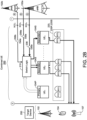
- At least two UEs 104 cooperate to provide a combined UE 200 to leverage carrier aggregation capabilities supported by a network base station 102, 102a (e.g., eNB) within an LTE-Advanced network 100.
- a network base station 102, 102a e.g., eNB
- the eNB 102a recognizes the combined UE 200 as a single UE associated with multiple CCs 220.
- the UE 1 may be designated as a primary UE 104P for connecting with the eNB 102 on a PCC 220P, while the remaining at least one UE 104 (e.g., UE 2 -UE n ) 104 of the combined UE 200 may be designated as a corresponding secondary UE 104S.
- the UEs 104 associated with the combined UE 200 may share a single network identity and may operate in a combined-UE operating state to enable cross-carrier aggregation between the combined UE 200 and the eNB 102a.
- the primary UE 104P includes data processing hardware 105 (e.g., circuitry, silicon chip, etc.) and memory hardware 109 in communication with the data processing hardware 105.
- the memory hardware 109 may store instructions that when executed on the data processing hardware 105 cause the data processing hardware 105 to perform operations for connecting with the eNB 102a and instruct secondary UEs 104S to operate on one or more SCCs 220S.
- Each UE 104 similarly includes associated data processing hardware 105 and memory hardware 109.
- the primary UE 104P advertises a carrier aggregation (CA) capability 202 of the combined UE 200.
- the CA capability 202 includes a list of available CCs 220 (e.g., PCC, SCC 1 -SCC n ) collectively supported by the combined UE 200.
- the primary UE 104P supports primary and secondary component carriers PCC, SCC 1 ;
- the secondary UE2 120S supports secondary component carriers SCC 2 , SCC 3 , SCC 4 ;
- the secondary UE 3 120S supports secondary component carrier SCC 3 ;
- the secondary UE n supports secondary component carriers SCC 5 , SCC n .
- the combined UE 200 including the primary UE 104P and the plurality of secondary UEs 104S, advertises a CA capability 202 that includes the PCC 220P and each of the SCCs 220S (SCC 1 -SCC n ).
- the eNB 102a receives the CA capability 202 advertised by the combined UE 200 and provides a connection request 204 to the combined UE 200.
- the connection request 204 requests communication with the combined UE 200 on the PCC 220P or one of the SCCs 220S.
- the primary UE 104P serves as a point of contact for the combined UE 200 and facilitates communications to and from the combined UE 200.
- the primary UE 104P receives the connection request 204 from the eNB 102a on the PCC 220P and connects to the eNB 102a on the PCC 220P in response to receiving the connection request 204.
- the primary UE 104P may receive a configuration message 206 from the eNB 102a that instructs operation of at least one of the secondary CCs 220S, i.e., at least one of the SCC 1 -SCC n .
- the switch logic 210 e.g., software application
- the switch logic 210 allows the primary UE 104P to receive the configuration message 206 from the eNB 102a and instruct the at least one secondary UE 104S to operate on the at least one SCC 220S and receive data 208 ( FIG. 2B ) from the eNB 102a on the at least one SCC 220S.
- the eNB 102a may view the combined UE 200 as the single UE having the advertised CA capability 202 and the switch logic 210 executing on the primary UE 104P is responsible for routing the configuration message 206 to the appropriate secondary UE 104S for configuring the SCC 220S identified in the configuration message 206.
- the primary UE 104P receives a first configuration message 206 (denoted "A" in FIG. 2A ) on the PCC 220P from the eNB 102a that requests operation of the fifth SCC 5 220S.
- the primary UE 104P identifies the secondary UE n 104S associated with the fifth sees 220S and provides CC instructions 212 (denoted "A" in FIG. 2A ) to the secondary UE n 104S.
- the CC instructions 212 instruct the secondary UE n 104S to operate on the fifth sees 220S and receive data 208 from the eNB 102 on the fifth sees 220S.
- the CC instructions 212 received by the secondary UE n 104S enable the combined-UE operating state of the secondary UEn 104S to allow cross-carrier aggregation of the combined UE 200 including the primary UE 104P and the plurality of secondary UEs 104S. Accordingly, the CC instructions 212 provided to the secondary UE n 104S enables the secondary UE n 104S to receive the data 208 from the eNB 102a on the fifth SCC 5 220S.
- the switch logic 210 executing on the primary UE 1 104P schedules the transmission of the data 208 on the fifth sees 220S from the eNB 102 to the secondary UE n 104S.
- FIG. 2B shows the switch logic 210 enabling the secondary UE n 104S to operate on the fifth sees 220S to receive the data 208 transmitted from the eNB 102a (denoted "A" in FIG. 2B ).
- CC instructions 212 FIG.
- the secondary UEn 104S further instruct the secondary UEn 104S to send the received data 208 from the eNB 102a to a target device 250.
- the target device 250 may include another eNB 102, another UE 104, or a wireless node (e.g., access point) 107.
- the secondary UEn 104S receives the data 208 from the eNB 102 on the fifth sees 220S and subsequently sends the received data 208 to the target device 250.
- the combined UE 200 routes data 208 transmitted from the eNB 102 at point "1" to the target device 250 at point "2" by instructing one of the secondary UEs 104S (e.g., UE n ) to operate on the fifth sees 220S.
- secondary UE n 104S corresponds to a destination for the received data 208 and simply decodes the data 208 without further routing to the target device 250.
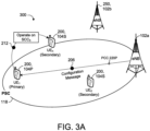
- FIGS. 3A and 3B provide an example network environment 300 including operation of the of the combined UE 200 of FIGS. 2A and 2B in response to receiving the first configuration message 206 (denoted "A" in FIG. 2A ) requesting operation on the fifth sees 220S.
- FIG. 3A shows the primary UE 1 104P of the combined UE 200 receiving the configuration message 206 from the eNB 102a on the PCC 220P.
- the PCC 220P serves a corresponding PSC 118 and the primary UE 1 104P is located within the PSC 118.
- the primary UE 1 104P instructs the secondary UE n 104S to operate on the fifth sees 220S.
- the primary UE 1 104P provides the CC instructions 212 (denoted "A" in FIG. 2A ) to the secondary UE n 104S.
- the secondary UE n 104S may receive the CC instructions 212 while operating in an idle mode.
- the CC instructions 212 instruct enabling the secondary UE n 104S to receive the data 208 from the eNB 102a on the fifth SCC 5 220S.
- FIG. 3B shows the secondary UE n 104S receiving the data 208 from the eNB 102a on the fifth SCC 5 220S.
- the enabled fifth sees 220S serves a corresponding SSC 5 120 and the secondary UE n 104S is located within the SSC 5 120.
- the coverage provided by the PSC 118 and the SSC 5 120 may be different.
- the secondary UE n 104S establishes connection with the SSC 5 120 via the eNB 102a to receive the data 208 on the fifth sees 220S.
- the secondary UE n 104S operating on the fifth sees 220S sends the received data 208 from the eNB 102a to the target device 250 including another eNB 102b.
- the primary UE 1 104P instructs (e.g., via the CC instructs 212) the secondary UE n 104S to send the received data 208 to the other eNB 102b.
- the primary UE 1 104P uses cross-carrier scheduling to schedule the transmission of the data 208 from the eNB 102a to the secondary UE n 104S on the fifth sees 220S.
- the eNB 102a may send low latency commands, such as DL and UL grants and/or timing and power control corrections, on the PCC 220P for execution by the secondary UE n 104S on the fifth sees 220S.
- Cross-carrier scheduling advantageously configures the fifth sees 220S in real time based on the configuration message 206 received on the PCC 220P.
- the switch logic 210 executing on the primary UE 1 104P provides the low latency commands received on the PCC 220P to the secondary UE n 104S in less than one millisecond to enable the fifth sees 220S and receive the data 208 from the eNB 102a thereon.
- the primary UE 1 104P instructs the secondary UE n 104S to operate on the fifth sees 220S without cross-carrier scheduling such that the secondary UE n 104S performs a cell search to connect with the eNB 102a on the fifth sees 220S for receiving the data 208 therefrom.
- the eNB 102a may provide separate configuration messages 206 to the combined UE 200 that instruct operation on other SCCs 220S associated with one or more of the primary UE 1 104P and/or the other secondary UEs 104S. In doing so, the eNB 102a may aggregate multiple SCCs 220S for transmitting data 208 and the switch logic 210 executing on the primary UE 1 104P may route the data 208 on each corresponding SCC 220S to the associated one of the UEs 104 of the combined UE 200. Each UE 104 receiving the data 208 on the associated SCC 220S may separately send the received data 208 to the target device 250 that includes the other eNB 102b.
- the multiple UEs 104 of the combined UE 200 each receiving the data 208 and sending the received data 208 to the target device 250 provides multiple receive antennas to execute uplink multiple-input multiple-output (MIMO) data 208 transmissions to the target device 250.
- MIMO uplink multiple-input multiple-output
- the enabling of the combined-UE operating state to allow cross-carrier aggregation of the combined UE 200 increases the number of uplink and downlink carriers aggregated compared the number of aggregated carriers permitted by only a single UE 104 due to battery power and mobility constraints.
- the primary UE 1 104P also receives a second configuration message 206 (denoted "B" in FIG. 2A ) on the PCC 220P from the eNB 102a that requests operation of the second SCC 2 and the fourth SCC 4 .
- the primary UE 1 104P may receive the first and second configuration messages 206 concurrently or separately.
- the primary UE 1 104P identifies the secondary UE 2 104S associated with the second SCC 2 220S and the fourth SCC 4 220S and provides CC instructions 212 (denoted "B" in FIG. 2A ) to the secondary UE 2 104S.
- the CC instructions 212 instruct the secondary UE n 104S to operate on the second SCC 2 220S and receive data 208a from the eNB 102a on the second SCC 2 220S, and to operate on the fourth SCC 4 220S to receive data 208b from another eNB 102b.
- the CC instructions 212 received by the secondary UE 2 104S enable the combined-UE operating state of the secondary UE 2 104S to allow cross-carrier aggregation of the combined UE 200 including the primary UE 104P and the plurality of secondary UEs 104S.
- the CC instructions 212 provided to the secondary UE 2 104S enables the secondary UE n 104S to receive the data 208a from the eNB 102a on the second SCC 2 220S and to receive the data 208b from the other eNB 102b on the fourth SCC 4 220S.
- the switch logic 210 executing on the primary UE 1 104P schedules the transmission of the data 208a on the second SCC 2 220S from the eNB 102a to the secondary UE 2 104S and the transmission of the data 208b on the fourth SCC 4 220S from the eNB 102b to the secondary UE 2 104S.
- FIG. 2B shows the switch logic 210 enabling the secondary UE 2 104S to operate on the second SCC 2 220S to receive the data 208a transmitted from the eNB 102a (denoted "B" in FIG. 2B).
- CC instructions 212 FIG. 2A
- the target device 250 may include another eNB 102, another UE 104, or a wireless node (e.g., access point) 107.
- the secondary UE 2 104S receives the data 208a from the eNB 102a on the second SCC 2 220S, receives the data 208b from the eNB 102b on the fourth SCC 4 220S, and subsequently sends the received data 208a, 208b to the target device 250.
- the secondary UE 2 104S may send the received data 208a, 208b to the target device 250 separately or together.
- the combined UE 200 routes the data 208a, 208b transmitted from the eNBs 102a, 102b at point "1" to the target device 250 at point "2" by instructing one of the secondary UEs 104S (e.g., UE 2 ) to operate on both the second SCC 2 220S and the fourth SCC 4 220S.
- the secondary UEs 104S e.g., UE 2
- FIGS. 4A-4D provide an example network environment 400 including operation of the combined UE 200 of FIGS. 2A and 2B in response to receiving the second configuration message 206 (denoted "B" in FIG. 2A ) requesting operation on the second SCC 2 220S and the fourth SCC 4 220S.
- FIGS. 4A and 4B show the primary UE 1 104P of the combined UE 200 receiving the configuration message 206 from the eNB 102a on the PCC 220P.
- the PCC 220P serves the corresponding PSC 118 and the primary UE 1 104P is located within the PSC 118.
- the primary UE 1 104P instructs the secondary UE 2 104S to operate on the second SCC 2 220S ( FIG. 4A ) and also instructs the secondary UE 2 104S to operate on the fourth SCC 4 220S ( FIG. 4B ).
- the primary UE 1 104P provides the CC instructions 212 (denoted "B" in FIG. 2A ) to the secondary UE 2 104S.
- the secondary UE 2 104S may receive the CC instructions 212 while operating in an idle mode.
- the CC instructions 212 instruct enabling the secondary UE 2 104S to receive the data 208a from the eNB 102a on the second SCC 2 220S and to receive the data 208b from the other eNB 102b on the fourth SCC 4 220S.
- the primary UE 1 104P provides a single set of CC instructions 212 to the secondary UE 2 104S to instruct the secondary UE 2 104S to operate on both the second SCC 2 220S and the fourth SCC 4 220S for receiving the data 208a, 208b from the associated eNB 102a, 102b.
- the primary UE 1 104P provides separate CC instructions 212 to the secondary UE 2 104S each instructing the secondary UE 2 104S to operate on the associated one of the second SCC 2 220S or the fourth SCC 4 220S.
- FIG. 4C shows the secondary UE 2 104S receiving the data 208a from the eNB 102a on the second SCC 2 220S.
- the enabled second SCC 2 220S serves a corresponding SSC 2 220S and the second SCC 2 220S is located within the SSC 2 120.
- the SSC 2 120 may provide a different coverage than the coverage provided by PSC 118.
- the secondary UE 2 104S establishes connection with the SSC 2 120 via the eNB 102a to receive the data 208a on the second SCC 2 220S.
- FIG. 4D shows the secondary UE 2 104S receiving the data 208b from the other eNB 102b on the fourth SCC 4 220S.
- the fourth SCC 4 220S serves a corresponding SSC 4 120 providing a different coverage to the secondary UE 2 104S than the coverage provided to the secondary UE 2 104S by the SSC 2 120 served by the second SCC 2 220S of FIG. 4C .
- the secondary UE 2 104S establishes connection with the SSC 4 120 via the eNB 102b to receive the data 208b on the fourth SCC 4 220S. Accordingly, the secondary UE2 104S is dually connected to each of the eNBs 102a, 102b.
- the secondary UE 2 104S operating on the second SSC 2 220S sends the received data 208a, 208b from the eNBs 102a, 102b to the target device 250 including another UE 104.
- the other UE 104 associated with the target device 250 may be associated with the combined UE 200 or may be a distinct UE 104 having an associated network identity separately recognized by the eNB 102a.
- the primary UE 1 104P instructs (e.g., via the CC instructs 212) the secondary UE 2 104S to send the received data 208a, 208b to the other UE 104 associated with the target device 250.
- the primary UE 1 104P uses cross-carrier scheduling to schedule the transmission of the data 208a from the eNB 102a to the secondary UE 2 104S on the second SCC 2 220S and/or the transmission of the data 208b from the eNB 102b to the secondary UE 2 104S on the fourth SCC 4 220S.
- eNB 102a may send low latency commands, such as DL and UL grants and/or timing and power control corrections, on the PCC 220P for execution by the secondary UE 2 104S on the second SCC 5 220S and/or the fourth SCC 4 220S.
- the switch logic 210 executing on the primary UE 1 104P provides the low latency commands received on the PCC 220P to the secondary UE 2 104S in less than one millisecond to concurrently or separately enabling the second SCC 2 220S for receiving the data 208a from the eNB 102a and enabling the fourth SCC 4 220S for receiving the data 208b from the other eNB 102b.
- the primary UE 1 104P instructs the secondary UE 2 104S to operate on the second SSC 2 220S and the fourth SSC 4 220S without cross-carrier scheduling such that the secondary UE 2 104S performs cell searches to connect with the eNBs 102a, 102b for receiving the associated data 208a, 208b.
- FIGS. 5A and 5B are diagrams 500a, 500b illustrating example operations performed by the primary UE 104P of the combined UE 200 for carrier aggregation with cross-carrier scheduling ( FIG. 5A ) and without cross-carrier scheduling ( FIG. 5B ).
- the diagrams may be described with reference to FIGS. 2A and 2B after the primary UE 104P advertises the carrier aggregation (CA) capability 202 for the combined UE 200.
- the vertical y-axis indicates time increasing from the top to the bottom.
- the eNB 102 and the primary UE 104P perform an initial network attach procedure ("Network Attach") to register the primary UE 104P, and more specifically, the combined UE, with the LTE network 100.
- Network Attach initial network attach procedure
- the eNB 102 broadcasts LTE signals and the primary UE 104P sends a network attach request to the eNB 102.
- the eNB 102 transmits downlink data including a connection request 204 to the primary UE 104P on a primary CC (PCC) 220P.
- the connection request 204 may request communicating on one of the PCC 220P or at least one secondary CC (SCC) 220S.
- the primary UE 104P then connects to the eNB 102 on the PCC 220P by transmitting uplink data to the eNB 102.
- the primary UE 104P After primary UE 104P connects to the eNB 102 on the PCC 220P, the eNB 102 and the primary UE 104P perform a Carrier Aggregation procedure to configure at least one SCC 220S.
- the primary UE 104P receives a configuration message 206 from the eNB 102 instructing operation of the at least one SCC 220S.
- the primary UE 104P identifies at least one secondary UE 104S associated with the at least one SCC 220S. Thereafter, the primary UE 104P routes the configuration message 206 to the switch logic 210 executing on the data processing hardware 105 of the primary UE 104P, and the switch logic 210 routes the configuration message 206 to the at least one secondary UE 104S.
- the switch logic 210 provides the CC instructions 212 to the at least one secondary UE 104S to operate on the at least one SCC 220S and receive data 208 from the eNB 102 on the at least one SCC 220S. Thereafter, the eNB 102 transmits a downlink carrier activation signal to the primary UE 104P to activate the at least one SCC 220S. The downlink carrier activation signal is passed to the switch logic 210 and onto the at least one secondary UE 104S.
- FIG. 5A shows the eNB 102 using cross-carrier scheduling to configure a target SCC 220S on the PCC 220P.
- the eNB 102 transmits a downlink control signal to the primary UE 104P on the PCC 220P that instructs the primary UE 104P to pass or handover control to the secondary UE 104S.
- the primary UE 104P may pass the control signal to the secondary UE 104S to enable the secondary UE 104S associated with the target SCC 220S to receive the data 208 from the eNB 102.
- FIG. 5B omits the passing of the control signals and simply allows the secondary UE 104S to operate on the SCC 220S and connect with the eNB 102 to receive data therefrom.
- the diagrams 500a, 500b both include the eNB 102 providing downlink data 208 to both the primary UE 104P on the PCC 220P and the secondary UE 104S on the SCC 220S.
- the primary UE 104P may provide uplink data 208 back to the eNB 102 on the PCC 220P and the secondary UE 104S may provide uplink data 208 back to the eNB 102 on the SCC 220S.
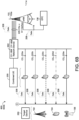
- a combined UE environment 600, 600a-b includes a network device 602 in communication with a combined UE 200 and a network base station (e.g., eNB) 102.
- the eNB 102 may communicate with the EPC 106 over the S1 interface 114.
- the eNB 102 receives packets of data 208 from the EPC 106 and routes the data 208 through the combined UE 200 to a destination D.
- the destination D may include a target device 250, such as another eNB 102, another UE 104, or a wireless node (e.g., access point) 107.
- the network device 602 may include customer premises equipment (CPE) such as a router or modem configured to wirelessly connect to a plurality of UEs 104 and one or more eNBs 102.
- CPE customer premises equipment
- the network device 602 includes data processing hardware 604 and memory hardware 606 in communication with the data processing hardware 604.
- the memory hardware 606 may store instructions that when executed on the data processing hardware 604 cause the data processing hardware 604 to perform operations for connecting with the eNB 102 and routing data 208 through the combined UE 200.
- the network device 602 receives a communication request 610 from the eNB 102 for delivery of data 208 ( FIG. 6B ) to the destination D (e.g., target device 250).
- the network device 602 is configured to route the data 208 associated with the communication request 610 through the combined UE 200 to the destination D.
- the combined UE 200 includes multiple slave UEs 104 (e.g., UE 1 -UE 5 ) each having an associated component carrier (CC) 220.
- the network device 602 includes data processing hardware 604 and memory hardware 606 in communication with the data processing hardware 604.
- the memory hardware 606 may store instructions that when executed on the data processing hardware 604 cause the data processing hardware 604 to perform operations for connecting with the eNB 102 and each slave UE 104 to route the data 208 through the combined UE 200 to the destination D.
- the network device 602 assigns each slave UE 104 with an associated CC 220, 220a-e that is different from each other CC 220 associated with each other slave UE 104. Accordingly, the combined UE 200 may place each slave UE 104 on a separate CC 220 so that each of the CCs 220 may be aggregated to utilize more of the wireless spectrum, and thereby increase a threshold efficiency in a fixed wireless access service (e.g., citizens Broadband Radio Service (CBRS) band). In the example shown, the combined UE 200 includes five slave UEs 104 to allow up to five (5) CCs 220 to be aggregated.
- CBRS Citizens Broadband Radio Service
- a combined UE 200 including more slave UEs 104 for aggregating more than five (5) CCs 220. While the combined UE 200 may be recognized by the eNB 102 as a single UE associated with the CCs 220 of the slave UEs 104, each slave UE 104 may include an associated network identity that is different from each other network identity associated with each other slave UE 104.
- the network device 602 may provide combined-UE information 612 to the eNB 102.
- the combined-UE information 612 may include the network identity for each slave UE 104 of the combined UE 200 and/or each associated CC 220, 220a-e assigned to the slave UEs 104 of the combined UE 200.
- the eNB 102 may receive the combined-UE information 612.
- the eNB 102 tracks each slave UE 104 using the associated network identity and associated CC 220 to ensure that the slave UEs 104 remain on separate CCs 220. Maintaining the slave UEs 104 on separate CCs 220 insures that bandwidth is not shared between physical layer resources offered by each slave UE 104 of the combined UE 200.
- the eNB 102 may provide the combined-UE information 612 to the EPC 106 via the S1-Interface 114 to allow the EPC 106 (and PGW) to track each slave UE 104 using the associated network identity.
- the EPC 106 tracks each slave UE 104 using the associated network identity to allow packets of data 208 scheduled for transmission on one slave UE 104 to be rerouted to another slave UE 104.
- FIG. 6B shows the network device 602 (e.g., via the data processing hardware 604) routing the communication of data 208 through multiple slave UEs 104 of the combined UE 200 to the destination D (e.g., target device 250).
- the network device 602 routes the communication of data 208 by identifying at least one target slave UE 104 for routing the data 208 based on the CC 220 associated with the at least one target slave UE 104. Thereafter, the network device 602 schedules the routing of the communication of data 208 through the identified at least one target slave UE 104.
- the network device identifies multiple target slave UEs 104 (UE 1 -UE 5 ) and schedules concurrent routing of the communication of data 208 through the identified multiple target slave UEs 104.
- the eNB 102 may send the communication of data 208 across multiple CCs 220a-n each associated with one of the identified multiple target slave UEs 104 of the combined UE 200.
- the network device 602 may route the communication of data 208 on each CC 220a-n through the target slave UE 104 associated with the CC 220a-n.
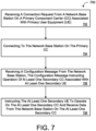
- FIG. 7 provides an example arrangement of operations for a method 700 of instructing at least one secondary UE 104S to operate on at least one secondary component carrier (SCC) 220S and receive data from a network base station 102 on the at least one SCC 220S.
- the method 700 includes receiving, at data processing hardware 105 of the primary UE 104P, a connection request 204 from the network base station 102a on a primary component carrier (PCC) 220P associated with the primary UE 104P.
- PCC primary component carrier
- the method 700 includes connecting, by the data processing hardware 105, to the network base station 102 on the PCC 220P.
- the method 700 includes receiving, at the data processing hardware 105, a configuration message 206 from the network base station 102.
- the configuration message 206 instructs operation of the at least one SCC 220S.
- the at least one SCC 220S is associated with at least one secondary UE 104S.
- the method 700 includes, instructing, by the data processing hardware 105, the at least one secondary UE 104S to operate on the at least one SCC 220S and receive data 208 from the network base station 102 on the at least one SCC 220S.
- FIG. 8 provides an example arrangement of operations for a method 800 of routing a communication of data from a network base station 102 through a combined user equipment (UE) 200 to a destination D.
- the destination may include a target device 250 such as, but not limited to, another network base station 102, another UE 104, or a wireless node (e.g., access point) 107.
- the method 800 includes receiving, at data processing hardware 604, a communication request 610 from the network base station 102 for delivery of data 208 to the destination D.
- the method 800 includes routing, by the data processing hardware 604, the communication of data 208 from the network base station 102 through the combined UE 200 to the destination D.
- the combined UE includes slave UEs 104 each in communication with the data processing hardware 604 and having an associated component carrier (CC) 220, 220a-e.
- the combined UE 200 is recognized by the network base station 102 as a single UE associated with the CCs 220a-e of the slave UEs 104.
- the method 800 includes identifying at least one target slave UE 104 for routing the communication of data 208 based on the CC 220 associated with the at least one target slave UE 104.
- the method includes scheduling the routing of the communication of data 208 through the identified at least one target slave UE 104.
- a software application may refer to computer software that causes a computing device to perform a task.
- a software application may be referred to as an "application,” an "app,” or a "program.”
- Example applications include, but are not limited to, system diagnostic applications, system management applications, system maintenance applications, word processing applications, spreadsheet applications, messaging applications, media streaming applications, social networking applications, and gaming applications.
- FIG. 9 is schematic view of an example computing device 900 that may be used to implement the systems and methods described in this document.
- the computing device 900 is intended to represent various forms of digital computers, such as laptops, desktops, workstations, personal digital assistants, servers, blade servers, mainframes, and other appropriate computers.
- the components shown here, their connections and relationships, and their functions, are meant to be exemplary only, and are not meant to limit implementations of the inventions described and/or claimed in this document.
- the computing device 900 includes a processor 910, memory 920, a storage device 930, a high-speed interface/controller 940 connecting to the memory 920 and high-speed expansion ports 990, and a low speed interface/controller 960 connecting to a low speed bus 970 and a storage device 930.
- a processor 910 processor 910
- memory 920 memory 920
- storage device 930 storage device 930
- high-speed interface/controller 940 connecting to the memory 920 and high-speed expansion ports 990
- a low speed interface/controller 960 connecting to a low speed bus 970 and a storage device 930.
- Each of the components 910, 920, 930, 940, 990, and 960 are interconnected using various busses, and may be mounted on a common motherboard or in other manners as appropriate.
- the processor 910 can process instructions for execution within the computing device 900, including instructions stored in the memory 920 or on the storage device 930 to display graphical information for a graphical user interface (GUI) on an external input/output device, such as display 980 coupled to high speed interface 940.
- GUI graphical user interface
- multiple processors and/or multiple buses may be used, as appropriate, along with multiple memories and types of memory.
- multiple computing devices 900 may be connected, with each device providing portions of the necessary operations (e.g., as a server bank, a group of blade servers, or a multi-processor system).
- the memory 920 stores information non-transitorily within the computing device 900.
- the memory 920 may be a computer-readable medium, a volatile memory unit(s), or non-volatile memory unit(s).
- the non-transitory memory 920 may be physical devices used to store programs (e.g., sequences of instructions) or data (e.g., program state information) on a temporary or permanent basis for use by the computing device 900.
- non-volatile memory examples include, but are not limited to, flash memory and read-only memory (ROM) / programmable read-only memory (PROM) / erasable programmable read-only memory (EPROM) / electronically erasable programmable read-only memory (EEPROM) (e.g., typically used for firmware, such as boot programs).
- volatile memory examples include, but are not limited to, random access memory (RAM), dynamic random access memory (DRAM), static random access memory (SRAM), phase change memory (PCM) as well as disks or tapes.
- the storage device 930 is capable of providing mass storage for the computing device 900.
- the storage device 930 is a computer-readable medium.
- the storage device 930 may be a floppy disk device, a hard disk device, an optical disk device, or a tape device, a flash memory or other similar solid state memory device, or an array of devices, including devices in a storage area network or other configurations.
- a computer program product is tangibly embodied in an information carrier.
- the computer program product contains instructions that, when executed, perform one or more methods, such as those described above.
- the information carrier is a computer- or machine-readable medium, such as the memory 920, the storage device 930, or memory on processor 910.
- the high speed controller 940 manages bandwidth-intensive operations for the computing device 900, while the low speed controller 960 manages lower bandwidth-intensive operations. Such allocation of duties is exemplary only.
- the high-speed controller 940 is coupled to the memory 920, the display 980 (e.g., through a graphics processor or accelerator), and to the high-speed expansion ports 990, which may accept various expansion cards (not shown).
- the low-speed controller 960 is coupled to the storage device 930 and a low-speed expansion port 990.
- the low-speed expansion port 990 which may include various communication ports (e.g., USB, Bluetooth, Ethernet, wireless Ethernet), may be coupled to one or more input/output devices, such as a keyboard, a pointing device, a scanner, or a networking device such as a switch or router, e.g., through a network adapter.
- input/output devices such as a keyboard, a pointing device, a scanner, or a networking device such as a switch or router, e.g., through a network adapter.
- the computing device 900 may be implemented in a number of different forms, as shown in the figure. For example, it may be implemented as a standard server 900a or multiple times in a group of such servers 900a, as a laptop computer 900b, or as part of a rack server system 900c.
- the computing device 900 (e.g., data processing hardware 105, 604) may be implemented on the UEs 104 and/or the network device 602.
- implementations of the systems and techniques described herein can be realized in digital electronic and/or optical circuitry, integrated circuitry, specially designed ASICs (application specific integrated circuits), computer hardware, firmware, software, and/or combinations thereof.
- ASICs application specific integrated circuits
- These various implementations can include implementation in one or more computer programs that are executable and/or interpretable on a programmable system including at least one programmable processor, which may be special or general purpose, coupled to receive data and instructions from, and to transmit data and instructions to, a storage system, at least one input device, and at least one output device.
- the processes and logic flows described in this specification can be performed by one or more programmable processors executing one or more computer programs to perform functions by operating on input data and generating output.
- the processes and logic flows can also be performed by special purpose logic circuitry, e.g., an FPGA (field programmable gate array) or an ASIC (application specific integrated circuit).
- processors suitable for the execution of a computer program include, by way of example, both general and special purpose microprocessors, and any one or more processors of any kind of digital computer.
- a processor will receive instructions and data from a read only memory or a random access memory or both.
- the essential elements of a computer are a processor for performing instructions and one or more memory devices for storing instructions and data.
- a computer will also include, or be operatively coupled to receive data from or transfer data to, or both, one or more mass storage devices for storing data, e.g., magnetic, magneto optical disks, or optical disks.
- mass storage devices for storing data
- a computer need not have such devices.
- Computer readable media suitable for storing computer program instructions and data include all forms of non-volatile memory, media and memory devices, including by way of example semiconductor memory devices, e.g., EPROM, EEPROM, and flash memory devices; magnetic disks, e.g., internal hard disks or removable disks; magneto optical disks; and CD ROM and DVD-ROM disks.
- the processor and the memory can be supplemented by, or incorporated in, special purpose logic circuitry.
- one or more aspects of the disclosure can be implemented on a computer having a display device, e.g., a CRT (cathode ray tube), LCD (liquid crystal display) monitor, or touch screen for displaying information to the user and optionally a keyboard and a pointing device, e.g., a mouse or a trackball, by which the user can provide input to the computer.
- a display device e.g., a CRT (cathode ray tube), LCD (liquid crystal display) monitor, or touch screen for displaying information to the user and optionally a keyboard and a pointing device, e.g., a mouse or a trackball, by which the user can provide input to the computer.
- Other kinds of devices can be used to provide interaction with a user as well; for example, feedback provided to the user can be any form of sensory feedback, e.g., visual feedback, auditory feedback, or tactile feedback; and input from the user can be received in any form, including acoustic, speech, or tactile input
Landscapes
- Engineering & Computer Science (AREA)
- Computer Networks & Wireless Communication (AREA)
- Signal Processing (AREA)
- Mobile Radio Communication Systems (AREA)
Claims (15)
- Ein Verfahren (700), das Folgendes umfasst:Empfangen einer Verbindungsanforderung (204) von einer Netzwerkbasisstation (102) auf einem primären Komponententräger, CC, (220P), der einem primären Benutzergerät, UE, (104P) zugeordnet ist, an der Datenverarbeitungshardware (105) des primären UEs (104P);Verbinden, durch die Datenverarbeitungshardware (105), mit der Netzwerkbasisstation (102) auf dem primären CC (220P);Empfangen einer Konfigurationsnachricht (206) von der Netzwerkbasisstation (102) an der Datenverarbeitungshardware (105), wobei die Konfigurationsnachricht (206) den Betrieb von mindestens einem sekundären CC (220S) anweist; undin Reaktion auf den Empfang der Konfigurationsnachricht (206):Identifizieren, durch die Datenverarbeitungshardware (105), mindestens eines sekundären UE (104S), das mit dem mindestens einen sekundären CC verbunden ist;Anweisen des mindestens einen sekundären UE (104S) durch die Datenverarbeitungshardware (105), mit dem mindestens einen sekundären CC (220S) zu arbeiten und Daten (208) von der Netzwerkbasisstation (102) auf dem mindestens einen sekundären CC (220S) zu empfangen; undErmöglichen eines kombinierten UE-Betriebszustands des mindestens einen sekundären UE (104S), wobei das kombinierte UE das primäre UE (104P) und das mindestens eine sekundäre UE (104S) umfasst.
- Verfahren (700) nach Anspruch 1, ferner umfassend, als Reaktion auf den Empfang der Konfigurationsnachricht (206), das Anweisen, durch die Datenverarbeitungshardware (105), des mindestens einen sekundären UE (104S), das auf dem mindestens einen sekundären CC (220S) arbeitet, die empfangenen Daten (208) von der Netzwerkbasisstation (102) an ein Zielgerät (250) zu senden.
- Verfahren (700) nach Anspruch 2, wobei das Zielgerät (250) mindestens eine andere Basisstation (102) oder ein anderes UE (104) umfasst.
- Verfahren (700) nach einem der Ansprüche 1 bis 3, ferner umfassend:Anzeigen einer Trägeraggregationsfähigkeit des kombinierten UE (200) durch die Datenverarbeitungshardware (105), wobei das kombinierte UE (200) von der Netzwerkbasisstation (102) als ein einzelnes UE (104) erkannt wird, das mit dem primären CC (220P) und dem mindestens einen sekundären CC (220S) verbunden ist; undals Reaktion auf das Anzeigen der Trägeraggregationsfähigkeit, Empfangen der Verbindungsanforderung (204), wobei die Verbindungsanforderung (204) für die Kommunikation mit dem primären CC (220P) oder dem mindestens einen sekundären CC (220S) erfolgt.
- Verfahren (700) nach einem der Ansprüche 1 bis 4, wobei der kombinierte UE-Betriebszustand die trägerübergreifende Aggregation des kombinierten UE (200) ermöglicht und wobei das kombinierte UE (200) von der Netzwerkbasisstation (102) als ein einzelnes UE (104) erkannt wird, das dem primären CC (220P) und dem mindestens einen sekundären CC (220S) zugeordnet ist.
- Verfahren (700) nach Anspruch 5, wobei das mindestens eine sekundäre UE (104S) mehrere sekundäre UEs (104S) umfasst und die Konfigurationsnachricht (206) anweist, ein sekundäres Ziel-UE (104S) zu aktivieren, wobei das sekundäre Zielgerät eines der mehreren sekundären UEs (104S) ist, das mit einem sekundären Ziel-CC (220S) verbunden ist, um die Daten (208) von der Netzwerkbasisstation (102) zu empfangen, und vorzugsweise weiter umfassend, nach dem Aktivieren des kombinierten UE-Betriebszustands des sekundären Ziel-UE (104S), das Planen der Übertragung von Daten (208) von der Netzwerkbasisstation (102) zu dem sekundären Ziel-UE (104S), und vorzugsweise weiter umfassend die Übertragung der Daten (208) von dem sekundären Ziel-UE (104S) zu einem Zielgerät (250).
- Verfahren (700) nach Anspruch 5, wobei der mindestens eine sekundäre CC (220S) mehrere sekundäre CCs (220S) umfasst und die Konfigurationsnachricht (206) anweist, ein sekundäres Ziel-UE (104S) in die Lage zu versetzen, auf einem ersten sekundären Ziel-CC (220S) zu arbeiten, um die Daten (208) von der Netzwerkbasisstation (102) zu empfangen, und auf einem zweiten sekundären Ziel-CC (220S) zu arbeiten, um Daten (208) von einer anderen Basisstation (102) zu empfangen.
- Verfahren (700) nach Anspruch 5, wobei das mindestens eine sekundäre UE (104S) eine Vielzahl von sekundären UEs (104S) umfasst und der mindestens eine sekundäre CC (220S) eine Vielzahl von sekundären CCs (220S) umfasst, und die Konfigurationsnachricht (206) anweist, ein erstes sekundäres Ziel-UE (104S), das mit einem ersten sekundären Ziel-CC (220S) verbunden ist, zu aktivieren, um die Daten (208) von der Basisstation (102) zu empfangen, und anweist, ein zweites sekundäres Ziel-UE (104S), das mit einem zweiten sekundären Ziel-CC (220S) verbunden ist, zu aktivieren, um Daten (208) von der Netzwerkbasisstation (102) zu empfangen.
- Ein System (100), das Folgendes umfasst:eine Netzwerkbasisstation (102); undeine Vielzahl von Benutzergeräten, UE, (104), die ein primäres UE (104P) und sekundäre UEs (104S) umfassen, wobei jedes UE (104) mit mindestens einem Komponententräger, CC, (220) verbunden ist,wobei das primäre UE (104P) so konfiguriert ist, dass es Operationen durchführt, die Folgendes umfassen:Empfangen einer Verbindungsanforderung (204) von der Netzwerkbasisstation (102) auf einem primären CC (220P), der mit dem primären UE (104P) verbunden ist;Verbinden mit der Netzwerkbasisstation (102) über den primären CC (220P);Empfangen einer Konfigurationsnachricht (206) von der Netzwerkbasisstation (102), wobei die Konfigurationsnachricht (206) den Betrieb von mindestens einem sekundären CC (220S) anweist; undin Reaktion auf den Empfang der Konfigurationsnachricht (206):Identifizieren mindestens eines sekundären UE (104S), das mit dem mindestens einen sekundären CC verbunden ist;Anweisen des mindestens einen sekundären UE (104S), auf dem mindestens einen sekundären CC (220S) zu arbeiten und Daten (208) von der Netzwerkbasisstation (102) auf dem mindestens einen sekundären CC (220S) zu empfangen; undErmöglichen eines kombinierten UE-Betriebszustands des mindestens einen sekundären UE (104S), wobei das kombinierte UE das primäre UE (104P) und das mindestens eine sekundäre UE (104S) umfasst.
- System (100) nach Anspruch 9, wobei die Operationen ferner aufweisen, als Reaktion auf den Empfang der Konfigurationsnachricht (206), Anweisen des mindestens einen sekundären UE (104S), das auf dem mindestens einen sekundären CC (220S) arbeitet, die empfangenen Daten (208) von der Netzwerkbasisstation (102) an ein Zielgerät (250) zu senden.
- Das System (100) nach Anspruch 9 oder 10, wobei das Zielgerät (250) mindestens eine andere Basisstation (102) oder ein anderes UE (104) umfasst.
- Das System (100) nach einem der Ansprüche 9 bis 11, wobei die Operationen ferner Folgendes umfassen:Anzeigen einer Trägeraggregationsfähigkeit des kombinierten UE (200), wobei das kombinierte UE (200) von der Netzwerkbasisstation (102) als ein einzelnes UE (104) erkannt wird, das mit dem primären CC (220P) und dem mindestens einen sekundären CC (220S) verbunden ist; undals Reaktion auf das Anzeigen der Trägeraggregationsfähigkeit, Empfangen der Verbindungsanforderung (204), wobei die Verbindungsanforderung (204) für die Kommunikation mit dem primären CC (220P) oder dem mindestens einen sekundären CC (220S) erfolgt.
- System (100) nach einem der Ansprüche 9 bis 12, wobei der kombinierte UE-Betriebszustand eine trägerübergreifende Aggregation des kombinierten UE (200) erlaubt, und wobei das kombinierte UE (200) von der Netzwerkbasisstation (102) als ein einzelnes UE (104) erkannt wird, das dem primären CC (220P) und dem mindestens einen sekundären CC (220S) zugeordnet ist, und wobei das mindestens eine sekundäre UE (104S) vorzugsweise eine Vielzahl von sekundären UEs (104S) umfasst, und die Konfigurationsnachricht (206) anweist, ein sekundäres Ziel-UE (104S), das mit einem sekundären Ziel-CC (220S) assoziiert ist, zu aktivieren, um die Daten (208) von der Netzwerkbasisstation (102) zu empfangen, und wobei die Operationen vorzugsweise weiterhin umfassen, nach dem Aktivieren des kombinierten UE-Betriebszustands des sekundären Ziel-UE (104S), das Planen der Übertragung von Daten (208) von der Netzwerkbasisstation (102) an das sekundäre Ziel-UE (104S), und wobei das sekundäre Ziel-UE (104S) vorzugsweise dafür ausgelegt ist, die Daten (208) von der Netzwerkbasisstation (102) an ein Zielgerät (250) zu übertragen.
- System (100) nach Anspruch 13, wobei das mindestens eine sekundäre CC (220S) eine Vielzahl sekundärer CCs (220S) umfasst und die Konfigurationsnachricht (206) anweist, ein sekundäres Ziel-UE (104S) in die Lage zu versetzen, mit einem ersten sekundären Ziel-CC (220S) zu arbeiten, um die Daten (208) von der Basisstation (102) zu empfangen, und mit einem zweiten sekundären Ziel-CC (220S) zu arbeiten, um Daten (208) von einer anderen Basisstation (102) zu empfangen.
- System (100) nach Anspruch 13, wobei das mindestens eine sekundäre UE (104S) eine Vielzahl von sekundären UEs (104S) umfasst und der mindestens eine sekundäre CC (220S) eine Vielzahl von sekundären CCs (220S) umfasst, und die Konfigurationsnachricht (206) anweist, ein erstes sekundäres Ziel-UE (104S), das mit einem ersten sekundären Ziel-CC (220S) verbunden ist, zu aktivieren, um die Daten (208) von der Basisstation (102) zu empfangen, und anweist, ein zweites sekundäres Ziel-UE (104S), das mit einem zweiten sekundären Ziel-CC (220S) verbunden ist, zu aktivieren, um Daten (208) von der Basisstation (102) zu empfangen.
Applications Claiming Priority (2)
| Application Number | Priority Date | Filing Date | Title |
|---|---|---|---|
| US15/385,350 US10420104B2 (en) | 2016-12-20 | 2016-12-20 | Carrier aggregation on combined user equipment |
| PCT/US2017/053968 WO2018118174A1 (en) | 2016-12-20 | 2017-09-28 | Carrier aggregation on combined user equipment |
Publications (2)
| Publication Number | Publication Date |
|---|---|
| EP3536074A1 EP3536074A1 (de) | 2019-09-11 |
| EP3536074B1 true EP3536074B1 (de) | 2024-06-26 |
Family
ID=60084090
Family Applications (1)
| Application Number | Title | Priority Date | Filing Date |
|---|---|---|---|
| EP17784475.0A Active EP3536074B1 (de) | 2016-12-20 | 2017-09-28 | Trägeraggregation auf kombiniertem benutzergerät |
Country Status (4)
| Country | Link |
|---|---|
| US (1) | US10420104B2 (de) |
| EP (1) | EP3536074B1 (de) |
| CN (2) | CN110089175B (de) |
| WO (1) | WO2018118174A1 (de) |
Families Citing this family (3)
| Publication number | Priority date | Publication date | Assignee | Title |
|---|---|---|---|---|
| US10420104B2 (en) * | 2016-12-20 | 2019-09-17 | Google Llc | Carrier aggregation on combined user equipment |
| CN108566311B (zh) * | 2018-07-24 | 2020-09-01 | Oppo广东移动通信有限公司 | 载波聚合配置方法及相关设备 |
| WO2020037457A1 (en) * | 2018-08-20 | 2020-02-27 | Qualcomm Incorporated | Synchronized scheduling for carrier aggregation |
Citations (1)
| Publication number | Priority date | Publication date | Assignee | Title |
|---|---|---|---|---|
| WO2015170392A1 (ja) * | 2014-05-08 | 2015-11-12 | 富士通株式会社 | 無線通信システム、端末、基地局および処理方法 |
Family Cites Families (19)
| Publication number | Priority date | Publication date | Assignee | Title |
|---|---|---|---|---|
| EP2187691A1 (de) * | 2008-11-12 | 2010-05-19 | Alcatel, Lucent | Verfahren zur Funkkommunikation zwischen einer Basisstation und einem Benutzerendgerät unter Verwendung einer Übertragung auf Komponententrägern auf der Basis von Kontrollinformation sowie Basisstation, Benutzerendgerät und Kommunikationsnetz dafür |
| TWI392392B (zh) | 2009-06-18 | 2013-04-01 | Ind Tech Res Inst | 多載波通訊系統下的載波組態方法 |
| US20110081913A1 (en) * | 2009-10-02 | 2011-04-07 | Lee Jung A | Method of bandwidth extension by aggregating backwards compatible and non-backwards compatible carriers |
| CN102131244B (zh) * | 2010-01-15 | 2016-01-20 | 中兴通讯股份有限公司 | 一种辅载波配对信息传递和获取的方法和系统 |
| US20120314675A1 (en) * | 2010-02-21 | 2012-12-13 | Lg Electronics Inc. | Method for managing carrier aggregation sets, and related devices |
| US8483156B2 (en) * | 2010-05-03 | 2013-07-09 | Nokia Siemens Networks Oy | Feedback for inter-radio access technology carrier aggregation |
| KR20120034509A (ko) * | 2010-10-01 | 2012-04-12 | 주식회사 팬택 | 다중 요소 반송파 시스템에서 전력조정을 위한 제어정보의 전송장치 및 방법 |
| CN104126281B (zh) * | 2012-01-11 | 2018-06-15 | 诺基亚通信公司 | 用于站间载波聚合的辅小区准备的方法和装置 |
| ES2671419T3 (es) * | 2012-03-23 | 2018-06-06 | Mediatek Inc. | Métodos para la agregación de portadoras multi-punto de capa física y la configuración de retroalimentación de multi-punto |
| US9184886B2 (en) * | 2012-08-10 | 2015-11-10 | Blackberry Limited | TD LTE secondary component carrier in unlicensed bands |
| JP6534619B2 (ja) | 2013-03-15 | 2019-06-26 | アップル インコーポレイテッドApple Inc. | Lteキャリアアグリゲーションにおけるセカンダリコンポーネントキャリアの将来のスケジューリング |
| CN103298123B (zh) * | 2013-05-27 | 2015-11-11 | 大唐移动通信设备有限公司 | 一种载波聚合辅载波激活与去激活方法及装置 |
| KR102133287B1 (ko) * | 2013-07-26 | 2020-07-13 | 삼성전자 주식회사 | 이동통신 시스템에서 효과적인 다중 반송파 다중 셀 스케줄링 장치 및 방법 |
| US9572040B2 (en) | 2013-10-22 | 2017-02-14 | Acer Incorporated | Unlicensed spectrum sharing method, base station using the same, and user equipment using the same |
| CN105338534B (zh) * | 2014-06-19 | 2020-07-31 | 索尼公司 | 无线通信系统中的装置和方法 |
| US9918290B2 (en) * | 2014-06-27 | 2018-03-13 | Samsung Electronics Co., Ltd. | Methods and apparatus for inter-cell device-to-device communication and discovery |
| US10805926B2 (en) * | 2014-08-07 | 2020-10-13 | Apple Inc. | Systems, methods, and devices for proximity services for multi-carrier capable mobile devices |
| WO2016105046A1 (ko) * | 2014-12-21 | 2016-06-30 | 엘지전자 주식회사 | 무선 통신 시스템에서 트래픽 분산을 위한 네트워크 협력 통신 방법 및 이를 위한 장치 |
| US10420104B2 (en) * | 2016-12-20 | 2019-09-17 | Google Llc | Carrier aggregation on combined user equipment |
-
2016
- 2016-12-20 US US15/385,350 patent/US10420104B2/en active Active
-
2017
- 2017-09-28 WO PCT/US2017/053968 patent/WO2018118174A1/en not_active Ceased
- 2017-09-28 CN CN201780076794.1A patent/CN110089175B/zh active Active
- 2017-09-28 CN CN202310344916.8A patent/CN116471678B/zh active Active
- 2017-09-28 EP EP17784475.0A patent/EP3536074B1/de active Active
Patent Citations (2)
| Publication number | Priority date | Publication date | Assignee | Title |
|---|---|---|---|---|
| WO2015170392A1 (ja) * | 2014-05-08 | 2015-11-12 | 富士通株式会社 | 無線通信システム、端末、基地局および処理方法 |
| EP3142433A1 (de) * | 2014-05-08 | 2017-03-15 | Fujitsu Limited | Drahtloses kommunikationssystem, endgerät, basisstation und kommunikationsverfahren |
Also Published As
| Publication number | Publication date |
|---|---|
| CN116471678A (zh) | 2023-07-21 |
| CN110089175B (zh) | 2023-04-21 |
| CN110089175A (zh) | 2019-08-02 |
| EP3536074A1 (de) | 2019-09-11 |
| CN116471678B (zh) | 2026-03-17 |
| WO2018118174A1 (en) | 2018-06-28 |
| US20180176917A1 (en) | 2018-06-21 |
| US10420104B2 (en) | 2019-09-17 |
Similar Documents
| Publication | Publication Date | Title |
|---|---|---|
| US12470941B2 (en) | Systems and methods for concurrent spectrum usage within actively used spectrum | |
| CN107210882B (zh) | 支持载波聚合的无线通信系统中的ue能力的每载波分量信令 | |
| CN104205689B (zh) | 增强物理下行链路控制信道(ePDCCH)小区间干扰协调(ICIC) | |
| CN103222320B (zh) | 一种载波聚合调度装置、载波聚合调度方法和基站 | |
| EP2627138A1 (de) | Verfahren und vorrichtung zur verarbeitung von trägeraggregationskapazitäten | |
| CN115642995A (zh) | 一种用户设备、无线接入网络节点及其进行的方法 | |
| US20210297892A1 (en) | Integrated Access Backhaul Nodes that Support Multiple Mobile Terminations | |
| WO2015166801A1 (ja) | 基地局装置、端末装置、および通信方法 | |
| WO2012163023A1 (zh) | 分配多载波资源的方法、基站、和终端 | |
| WO2022086409A1 (en) | Direct current (dc) location reporting for intra-band uplink carrier aggregation (ca) | |
| CN103238362A (zh) | 基于群组消息的载波聚合控制 | |
| JP2024502356A (ja) | サイドリンクにおける不連続受信の構成 | |
| WO2015166792A1 (ja) | 基地局装置、端末装置、および通信方法 | |
| CN107534984A (zh) | 一种分量载波组的配置方法及设备 | |
| WO2023200483A1 (en) | Time division duplex pattern configuration for cellular networks | |
| US10420104B2 (en) | Carrier aggregation on combined user equipment | |
| WO2023093827A1 (zh) | 一种通信方法及装置 | |
| TWI652921B (zh) | 用戶設備及虛擬載波的操作方法 | |
| WO2019200507A1 (en) | Control of d2d duplication | |
| CN112806078A (zh) | 网络节点之间的资源调度 | |
| JP2023547929A (ja) | リソース割り当て方法、装置及び端末 | |
| TW202446020A (zh) | 具有子帶全雙工資源的時隙期間排程 |
Legal Events
| Date | Code | Title | Description |
|---|---|---|---|
| STAA | Information on the status of an ep patent application or granted ep patent |
Free format text: STATUS: UNKNOWN |
|
| STAA | Information on the status of an ep patent application or granted ep patent |
Free format text: STATUS: THE INTERNATIONAL PUBLICATION HAS BEEN MADE |
|
| PUAI | Public reference made under article 153(3) epc to a published international application that has entered the european phase |
Free format text: ORIGINAL CODE: 0009012 |
|
| STAA | Information on the status of an ep patent application or granted ep patent |
Free format text: STATUS: REQUEST FOR EXAMINATION WAS MADE |
|
| 17P | Request for examination filed |
Effective date: 20190604 |
|
| AK | Designated contracting states |
Kind code of ref document: A1 Designated state(s): AL AT BE BG CH CY CZ DE DK EE ES FI FR GB GR HR HU IE IS IT LI LT LU LV MC MK MT NL NO PL PT RO RS SE SI SK SM TR |
|
| AX | Request for extension of the european patent |
Extension state: BA ME |
|
| DAV | Request for validation of the european patent (deleted) | ||
| DAX | Request for extension of the european patent (deleted) | ||
| STAA | Information on the status of an ep patent application or granted ep patent |
Free format text: STATUS: EXAMINATION IS IN PROGRESS |
|
| 17Q | First examination report despatched |
Effective date: 20200703 |
|
| GRAP | Despatch of communication of intention to grant a patent |
Free format text: ORIGINAL CODE: EPIDOSNIGR1 |
|
| STAA | Information on the status of an ep patent application or granted ep patent |
Free format text: STATUS: GRANT OF PATENT IS INTENDED |
|
| INTG | Intention to grant announced |
Effective date: 20210816 |
|
| GRAJ | Information related to disapproval of communication of intention to grant by the applicant or resumption of examination proceedings by the epo deleted |
Free format text: ORIGINAL CODE: EPIDOSDIGR1 |
|
| STAA | Information on the status of an ep patent application or granted ep patent |
Free format text: STATUS: EXAMINATION IS IN PROGRESS |
|
| INTC | Intention to grant announced (deleted) | ||
| GRAJ | Information related to disapproval of communication of intention to grant by the applicant or resumption of examination proceedings by the epo deleted |
Free format text: ORIGINAL CODE: EPIDOSDIGR1 |
|
| GRAP | Despatch of communication of intention to grant a patent |
Free format text: ORIGINAL CODE: EPIDOSNIGR1 |
|
| GRAP | Despatch of communication of intention to grant a patent |
Free format text: ORIGINAL CODE: EPIDOSNIGR1 |
|
| STAA | Information on the status of an ep patent application or granted ep patent |
Free format text: STATUS: GRANT OF PATENT IS INTENDED |
|
| INTG | Intention to grant announced |
Effective date: 20240116 |
|
| GRAS | Grant fee paid |
Free format text: ORIGINAL CODE: EPIDOSNIGR3 |
|
| GRAA | (expected) grant |
Free format text: ORIGINAL CODE: 0009210 |
|
| STAA | Information on the status of an ep patent application or granted ep patent |
Free format text: STATUS: THE PATENT HAS BEEN GRANTED |
|
| AK | Designated contracting states |
Kind code of ref document: B1 Designated state(s): AL AT BE BG CH CY CZ DE DK EE ES FI FR GB GR HR HU IE IS IT LI LT LU LV MC MK MT NL NO PL PT RO RS SE SI SK SM TR |
|
| REG | Reference to a national code |
Ref country code: GB Ref legal event code: FG4D |
|
| REG | Reference to a national code |
Ref country code: CH Ref legal event code: EP |
|
| REG | Reference to a national code |
Ref country code: DE Ref legal event code: R096 Ref document number: 602017082829 Country of ref document: DE |
|
| P01 | Opt-out of the competence of the unified patent court (upc) registered |
Free format text: CASE NUMBER: APP_43365/2024 Effective date: 20240724 |
|
| PG25 | Lapsed in a contracting state [announced via postgrant information from national office to epo] |
Ref country code: BG Free format text: LAPSE BECAUSE OF FAILURE TO SUBMIT A TRANSLATION OF THE DESCRIPTION OR TO PAY THE FEE WITHIN THE PRESCRIBED TIME-LIMIT Effective date: 20240626 |
|
| PG25 | Lapsed in a contracting state [announced via postgrant information from national office to epo] |
Ref country code: FI Free format text: LAPSE BECAUSE OF FAILURE TO SUBMIT A TRANSLATION OF THE DESCRIPTION OR TO PAY THE FEE WITHIN THE PRESCRIBED TIME-LIMIT Effective date: 20240626 Ref country code: HR Free format text: LAPSE BECAUSE OF FAILURE TO SUBMIT A TRANSLATION OF THE DESCRIPTION OR TO PAY THE FEE WITHIN THE PRESCRIBED TIME-LIMIT Effective date: 20240626 |
|
| REG | Reference to a national code |
Ref country code: LT Ref legal event code: MG9D |
|
| PG25 | Lapsed in a contracting state [announced via postgrant information from national office to epo] |
Ref country code: GR Free format text: LAPSE BECAUSE OF FAILURE TO SUBMIT A TRANSLATION OF THE DESCRIPTION OR TO PAY THE FEE WITHIN THE PRESCRIBED TIME-LIMIT Effective date: 20240927 |
|
| PG25 | Lapsed in a contracting state [announced via postgrant information from national office to epo] |
Ref country code: LV Free format text: LAPSE BECAUSE OF FAILURE TO SUBMIT A TRANSLATION OF THE DESCRIPTION OR TO PAY THE FEE WITHIN THE PRESCRIBED TIME-LIMIT Effective date: 20240626 |
|
| REG | Reference to a national code |
Ref country code: NL Ref legal event code: MP Effective date: 20240626 |
|
| PG25 | Lapsed in a contracting state [announced via postgrant information from national office to epo] |
Ref country code: NO Free format text: LAPSE BECAUSE OF FAILURE TO SUBMIT A TRANSLATION OF THE DESCRIPTION OR TO PAY THE FEE WITHIN THE PRESCRIBED TIME-LIMIT Effective date: 20240926 Ref country code: LV Free format text: LAPSE BECAUSE OF FAILURE TO SUBMIT A TRANSLATION OF THE DESCRIPTION OR TO PAY THE FEE WITHIN THE PRESCRIBED TIME-LIMIT Effective date: 20240626 Ref country code: HR Free format text: LAPSE BECAUSE OF FAILURE TO SUBMIT A TRANSLATION OF THE DESCRIPTION OR TO PAY THE FEE WITHIN THE PRESCRIBED TIME-LIMIT Effective date: 20240626 Ref country code: GR Free format text: LAPSE BECAUSE OF FAILURE TO SUBMIT A TRANSLATION OF THE DESCRIPTION OR TO PAY THE FEE WITHIN THE PRESCRIBED TIME-LIMIT Effective date: 20240927 Ref country code: FI Free format text: LAPSE BECAUSE OF FAILURE TO SUBMIT A TRANSLATION OF THE DESCRIPTION OR TO PAY THE FEE WITHIN THE PRESCRIBED TIME-LIMIT Effective date: 20240626 Ref country code: BG Free format text: LAPSE BECAUSE OF FAILURE TO SUBMIT A TRANSLATION OF THE DESCRIPTION OR TO PAY THE FEE WITHIN THE PRESCRIBED TIME-LIMIT Effective date: 20240626 Ref country code: RS Free format text: LAPSE BECAUSE OF FAILURE TO SUBMIT A TRANSLATION OF THE DESCRIPTION OR TO PAY THE FEE WITHIN THE PRESCRIBED TIME-LIMIT Effective date: 20240926 |
|
| PG25 | Lapsed in a contracting state [announced via postgrant information from national office to epo] |
Ref country code: NL Free format text: LAPSE BECAUSE OF FAILURE TO SUBMIT A TRANSLATION OF THE DESCRIPTION OR TO PAY THE FEE WITHIN THE PRESCRIBED TIME-LIMIT Effective date: 20240626 |
|
| REG | Reference to a national code |
Ref country code: AT Ref legal event code: MK05 Ref document number: 1698721 Country of ref document: AT Kind code of ref document: T Effective date: 20240626 |
|
| PG25 | Lapsed in a contracting state [announced via postgrant information from national office to epo] |
Ref country code: NL Free format text: LAPSE BECAUSE OF FAILURE TO SUBMIT A TRANSLATION OF THE DESCRIPTION OR TO PAY THE FEE WITHIN THE PRESCRIBED TIME-LIMIT Effective date: 20240626 |
|
| PG25 | Lapsed in a contracting state [announced via postgrant information from national office to epo] |
Ref country code: PT Free format text: LAPSE BECAUSE OF FAILURE TO SUBMIT A TRANSLATION OF THE DESCRIPTION OR TO PAY THE FEE WITHIN THE PRESCRIBED TIME-LIMIT Effective date: 20241028 |
|
| PG25 | Lapsed in a contracting state [announced via postgrant information from national office to epo] |
Ref country code: PT Free format text: LAPSE BECAUSE OF FAILURE TO SUBMIT A TRANSLATION OF THE DESCRIPTION OR TO PAY THE FEE WITHIN THE PRESCRIBED TIME-LIMIT Effective date: 20241028 |
|
| PG25 | Lapsed in a contracting state [announced via postgrant information from national office to epo] |
Ref country code: PL Free format text: LAPSE BECAUSE OF FAILURE TO SUBMIT A TRANSLATION OF THE DESCRIPTION OR TO PAY THE FEE WITHIN THE PRESCRIBED TIME-LIMIT Effective date: 20240626 |
|
| PG25 | Lapsed in a contracting state [announced via postgrant information from national office to epo] |
Ref country code: EE Free format text: LAPSE BECAUSE OF FAILURE TO SUBMIT A TRANSLATION OF THE DESCRIPTION OR TO PAY THE FEE WITHIN THE PRESCRIBED TIME-LIMIT Effective date: 20240626 |
|
| PG25 | Lapsed in a contracting state [announced via postgrant information from national office to epo] |
Ref country code: AT Free format text: LAPSE BECAUSE OF FAILURE TO SUBMIT A TRANSLATION OF THE DESCRIPTION OR TO PAY THE FEE WITHIN THE PRESCRIBED TIME-LIMIT Effective date: 20240626 Ref country code: IS Free format text: LAPSE BECAUSE OF FAILURE TO SUBMIT A TRANSLATION OF THE DESCRIPTION OR TO PAY THE FEE WITHIN THE PRESCRIBED TIME-LIMIT Effective date: 20241026 |
|
| PG25 | Lapsed in a contracting state [announced via postgrant information from national office to epo] |
Ref country code: CZ Free format text: LAPSE BECAUSE OF FAILURE TO SUBMIT A TRANSLATION OF THE DESCRIPTION OR TO PAY THE FEE WITHIN THE PRESCRIBED TIME-LIMIT Effective date: 20240626 |
|
| PG25 | Lapsed in a contracting state [announced via postgrant information from national office to epo] |
Ref country code: RO Free format text: LAPSE BECAUSE OF FAILURE TO SUBMIT A TRANSLATION OF THE DESCRIPTION OR TO PAY THE FEE WITHIN THE PRESCRIBED TIME-LIMIT Effective date: 20240626 Ref country code: SK Free format text: LAPSE BECAUSE OF FAILURE TO SUBMIT A TRANSLATION OF THE DESCRIPTION OR TO PAY THE FEE WITHIN THE PRESCRIBED TIME-LIMIT Effective date: 20240626 |
|
| PG25 | Lapsed in a contracting state [announced via postgrant information from national office to epo] |
Ref country code: SM Free format text: LAPSE BECAUSE OF FAILURE TO SUBMIT A TRANSLATION OF THE DESCRIPTION OR TO PAY THE FEE WITHIN THE PRESCRIBED TIME-LIMIT Effective date: 20240626 Ref country code: ES Free format text: LAPSE BECAUSE OF FAILURE TO SUBMIT A TRANSLATION OF THE DESCRIPTION OR TO PAY THE FEE WITHIN THE PRESCRIBED TIME-LIMIT Effective date: 20240626 |
|
| PG25 | Lapsed in a contracting state [announced via postgrant information from national office to epo] |
Ref country code: SM Free format text: LAPSE BECAUSE OF FAILURE TO SUBMIT A TRANSLATION OF THE DESCRIPTION OR TO PAY THE FEE WITHIN THE PRESCRIBED TIME-LIMIT Effective date: 20240626 Ref country code: SK Free format text: LAPSE BECAUSE OF FAILURE TO SUBMIT A TRANSLATION OF THE DESCRIPTION OR TO PAY THE FEE WITHIN THE PRESCRIBED TIME-LIMIT Effective date: 20240626 Ref country code: RO Free format text: LAPSE BECAUSE OF FAILURE TO SUBMIT A TRANSLATION OF THE DESCRIPTION OR TO PAY THE FEE WITHIN THE PRESCRIBED TIME-LIMIT Effective date: 20240626 Ref country code: PL Free format text: LAPSE BECAUSE OF FAILURE TO SUBMIT A TRANSLATION OF THE DESCRIPTION OR TO PAY THE FEE WITHIN THE PRESCRIBED TIME-LIMIT Effective date: 20240626 Ref country code: IS Free format text: LAPSE BECAUSE OF FAILURE TO SUBMIT A TRANSLATION OF THE DESCRIPTION OR TO PAY THE FEE WITHIN THE PRESCRIBED TIME-LIMIT Effective date: 20241026 Ref country code: ES Free format text: LAPSE BECAUSE OF FAILURE TO SUBMIT A TRANSLATION OF THE DESCRIPTION OR TO PAY THE FEE WITHIN THE PRESCRIBED TIME-LIMIT Effective date: 20240626 Ref country code: EE Free format text: LAPSE BECAUSE OF FAILURE TO SUBMIT A TRANSLATION OF THE DESCRIPTION OR TO PAY THE FEE WITHIN THE PRESCRIBED TIME-LIMIT Effective date: 20240626 Ref country code: CZ Free format text: LAPSE BECAUSE OF FAILURE TO SUBMIT A TRANSLATION OF THE DESCRIPTION OR TO PAY THE FEE WITHIN THE PRESCRIBED TIME-LIMIT Effective date: 20240626 Ref country code: AT Free format text: LAPSE BECAUSE OF FAILURE TO SUBMIT A TRANSLATION OF THE DESCRIPTION OR TO PAY THE FEE WITHIN THE PRESCRIBED TIME-LIMIT Effective date: 20240626 |
|
| PG25 | Lapsed in a contracting state [announced via postgrant information from national office to epo] |
Ref country code: IT Free format text: LAPSE BECAUSE OF FAILURE TO SUBMIT A TRANSLATION OF THE DESCRIPTION OR TO PAY THE FEE WITHIN THE PRESCRIBED TIME-LIMIT Effective date: 20240626 |
|
| REG | Reference to a national code |
Ref country code: DE Ref legal event code: R097 Ref document number: 602017082829 Country of ref document: DE |
|
| PG25 | Lapsed in a contracting state [announced via postgrant information from national office to epo] |
Ref country code: DK Free format text: LAPSE BECAUSE OF FAILURE TO SUBMIT A TRANSLATION OF THE DESCRIPTION OR TO PAY THE FEE WITHIN THE PRESCRIBED TIME-LIMIT Effective date: 20240626 |
|
| PG25 | Lapsed in a contracting state [announced via postgrant information from national office to epo] |
Ref country code: MC Free format text: LAPSE BECAUSE OF FAILURE TO SUBMIT A TRANSLATION OF THE DESCRIPTION OR TO PAY THE FEE WITHIN THE PRESCRIBED TIME-LIMIT Effective date: 20240626 |
|
| REG | Reference to a national code |
Ref country code: CH Ref legal event code: PL |
|
| PLBE | No opposition filed within time limit |
Free format text: ORIGINAL CODE: 0009261 |
|
| STAA | Information on the status of an ep patent application or granted ep patent |
Free format text: STATUS: NO OPPOSITION FILED WITHIN TIME LIMIT |
|
| PG25 | Lapsed in a contracting state [announced via postgrant information from national office to epo] |
Ref country code: LU Free format text: LAPSE BECAUSE OF NON-PAYMENT OF DUE FEES Effective date: 20240928 |
|
| 26N | No opposition filed |
Effective date: 20250327 |
|
| REG | Reference to a national code |
Ref country code: BE Ref legal event code: MM Effective date: 20240930 |
|
| PG25 | Lapsed in a contracting state [announced via postgrant information from national office to epo] |
Ref country code: BE Free format text: LAPSE BECAUSE OF NON-PAYMENT OF DUE FEES Effective date: 20240930 |
|
| PG25 | Lapsed in a contracting state [announced via postgrant information from national office to epo] |
Ref country code: CH Free format text: LAPSE BECAUSE OF NON-PAYMENT OF DUE FEES Effective date: 20240930 |
|
| PG25 | Lapsed in a contracting state [announced via postgrant information from national office to epo] |
Ref country code: IE Free format text: LAPSE BECAUSE OF NON-PAYMENT OF DUE FEES Effective date: 20240928 |
|
| PG25 | Lapsed in a contracting state [announced via postgrant information from national office to epo] |
Ref country code: SE Free format text: LAPSE BECAUSE OF FAILURE TO SUBMIT A TRANSLATION OF THE DESCRIPTION OR TO PAY THE FEE WITHIN THE PRESCRIBED TIME-LIMIT Effective date: 20240626 |
|
| PGFP | Annual fee paid to national office [announced via postgrant information from national office to epo] |
Ref country code: DE Payment date: 20250929 Year of fee payment: 9 |
|
| PGFP | Annual fee paid to national office [announced via postgrant information from national office to epo] |
Ref country code: GB Payment date: 20250929 Year of fee payment: 9 |
|
| PGFP | Annual fee paid to national office [announced via postgrant information from national office to epo] |
Ref country code: FR Payment date: 20250925 Year of fee payment: 9 |
|
| PG25 | Lapsed in a contracting state [announced via postgrant information from national office to epo] |
Ref country code: CY Free format text: LAPSE BECAUSE OF FAILURE TO SUBMIT A TRANSLATION OF THE DESCRIPTION OR TO PAY THE FEE WITHIN THE PRESCRIBED TIME-LIMIT; INVALID AB INITIO Effective date: 20170928 |
|
| PG25 | Lapsed in a contracting state [announced via postgrant information from national office to epo] |
Ref country code: HU Free format text: LAPSE BECAUSE OF FAILURE TO SUBMIT A TRANSLATION OF THE DESCRIPTION OR TO PAY THE FEE WITHIN THE PRESCRIBED TIME-LIMIT; INVALID AB INITIO Effective date: 20170928 |