EP3535794B1 - Method of preparing battery anode slurries - Google Patents
Method of preparing battery anode slurries Download PDFInfo
- Publication number
- EP3535794B1 EP3535794B1 EP17868267.0A EP17868267A EP3535794B1 EP 3535794 B1 EP3535794 B1 EP 3535794B1 EP 17868267 A EP17868267 A EP 17868267A EP 3535794 B1 EP3535794 B1 EP 3535794B1
- Authority
- EP
- European Patent Office
- Prior art keywords
- suspension
- conductive agent
- carbon
- particle size
- anode slurry
- Prior art date
- Legal status (The legal status is an assumption and is not a legal conclusion. Google has not performed a legal analysis and makes no representation as to the accuracy of the status listed.)
- Active
Links
- 239000006256 anode slurry Substances 0.000 title claims description 135
- 238000000034 method Methods 0.000 title claims description 68
- 239000000725 suspension Substances 0.000 claims description 180
- 239000006258 conductive agent Substances 0.000 claims description 144
- 239000002245 particle Substances 0.000 claims description 128
- OKTJSMMVPCPJKN-UHFFFAOYSA-N Carbon Chemical compound [C] OKTJSMMVPCPJKN-UHFFFAOYSA-N 0.000 claims description 73
- 239000002210 silicon-based material Substances 0.000 claims description 66
- 239000002270 dispersing agent Substances 0.000 claims description 62
- 239000011230 binding agent Substances 0.000 claims description 49
- 238000002156 mixing Methods 0.000 claims description 49
- 239000007787 solid Substances 0.000 claims description 48
- XLYOFNOQVPJJNP-UHFFFAOYSA-N water Substances O XLYOFNOQVPJJNP-UHFFFAOYSA-N 0.000 claims description 46
- 239000000463 material Substances 0.000 claims description 36
- 239000002904 solvent Substances 0.000 claims description 35
- 239000004372 Polyvinyl alcohol Substances 0.000 claims description 30
- 229920002451 polyvinyl alcohol Polymers 0.000 claims description 30
- 238000009826 distribution Methods 0.000 claims description 28
- 229910052799 carbon Inorganic materials 0.000 claims description 27
- SECXISVLQFMRJM-UHFFFAOYSA-N N-Methylpyrrolidone Chemical compound CN1CCCC1=O SECXISVLQFMRJM-UHFFFAOYSA-N 0.000 claims description 26
- 239000002388 carbon-based active material Substances 0.000 claims description 24
- 229910052710 silicon Inorganic materials 0.000 claims description 22
- -1 Si/C Chemical compound 0.000 claims description 18
- CSCPPACGZOOCGX-UHFFFAOYSA-N Acetone Chemical compound CC(C)=O CSCPPACGZOOCGX-UHFFFAOYSA-N 0.000 claims description 17
- 229910002804 graphite Inorganic materials 0.000 claims description 16
- 239000010439 graphite Substances 0.000 claims description 16
- 229910021389 graphene Inorganic materials 0.000 claims description 14
- 229920002125 Sokalan® Polymers 0.000 claims description 13
- 239000004584 polyacrylic acid Substances 0.000 claims description 12
- 229920002134 Carboxymethyl cellulose Polymers 0.000 claims description 10
- LFQSCWFLJHTTHZ-UHFFFAOYSA-N Ethanol Chemical compound CCO LFQSCWFLJHTTHZ-UHFFFAOYSA-N 0.000 claims description 10
- OKKJLVBELUTLKV-UHFFFAOYSA-N Methanol Chemical compound OC OKKJLVBELUTLKV-UHFFFAOYSA-N 0.000 claims description 9
- 229920003171 Poly (ethylene oxide) Polymers 0.000 claims description 8
- VNWKTOKETHGBQD-UHFFFAOYSA-N methane Chemical class C VNWKTOKETHGBQD-UHFFFAOYSA-N 0.000 claims description 8
- VYPSYNLAJGMNEJ-UHFFFAOYSA-N Silicium dioxide Chemical compound O=[Si]=O VYPSYNLAJGMNEJ-UHFFFAOYSA-N 0.000 claims description 7
- 239000002134 carbon nanofiber Substances 0.000 claims description 7
- KFZMGEQAYNKOFK-UHFFFAOYSA-N Isopropanol Chemical compound CC(C)O KFZMGEQAYNKOFK-UHFFFAOYSA-N 0.000 claims description 6
- 239000006230 acetylene black Substances 0.000 claims description 6
- 229920000609 methyl cellulose Polymers 0.000 claims description 6
- 239000001923 methylcellulose Substances 0.000 claims description 6
- 235000010981 methylcellulose Nutrition 0.000 claims description 6
- BDERNNFJNOPAEC-UHFFFAOYSA-N propan-1-ol Chemical compound CCCO BDERNNFJNOPAEC-UHFFFAOYSA-N 0.000 claims description 6
- 229910052814 silicon oxide Inorganic materials 0.000 claims description 6
- 229920000663 Hydroxyethyl cellulose Polymers 0.000 claims description 5
- 239000004354 Hydroxyethyl cellulose Substances 0.000 claims description 5
- 235000019447 hydroxyethyl cellulose Nutrition 0.000 claims description 5
- 239000002931 mesocarbon microbead Substances 0.000 claims description 5
- 229920000036 polyvinylpyrrolidone Polymers 0.000 claims description 5
- 239000001267 polyvinylpyrrolidone Substances 0.000 claims description 5
- 235000013855 polyvinylpyrrolidone Nutrition 0.000 claims description 5
- DKGAVHZHDRPRBM-UHFFFAOYSA-N Tert-Butanol Chemical compound CC(C)(C)O DKGAVHZHDRPRBM-UHFFFAOYSA-N 0.000 claims description 4
- 239000002041 carbon nanotube Substances 0.000 claims description 4
- 229910021393 carbon nanotube Inorganic materials 0.000 claims description 4
- 229910021385 hard carbon Inorganic materials 0.000 claims description 4
- 239000002064 nanoplatelet Substances 0.000 claims description 4
- 229920002401 polyacrylamide Polymers 0.000 claims description 4
- 229910021384 soft carbon Inorganic materials 0.000 claims description 4
- 108010010803 Gelatin Proteins 0.000 claims description 3
- 229920002472 Starch Polymers 0.000 claims description 3
- 229910052783 alkali metal Inorganic materials 0.000 claims description 3
- 150000001340 alkali metals Chemical class 0.000 claims description 3
- 229910052784 alkaline earth metal Inorganic materials 0.000 claims description 3
- 150000001342 alkaline earth metals Chemical class 0.000 claims description 3
- 229920003090 carboxymethyl hydroxyethyl cellulose Polymers 0.000 claims description 3
- 229920002678 cellulose Polymers 0.000 claims description 3
- 239000001913 cellulose Substances 0.000 claims description 3
- 229920000159 gelatin Polymers 0.000 claims description 3
- 239000008273 gelatin Substances 0.000 claims description 3
- 235000019322 gelatine Nutrition 0.000 claims description 3
- 235000011852 gelatine desserts Nutrition 0.000 claims description 3
- 239000001814 pectin Substances 0.000 claims description 3
- 229920001277 pectin Polymers 0.000 claims description 3
- 235000010987 pectin Nutrition 0.000 claims description 3
- 229920001451 polypropylene glycol Polymers 0.000 claims description 3
- 229910052761 rare earth metal Inorganic materials 0.000 claims description 3
- 150000002910 rare earth metals Chemical class 0.000 claims description 3
- 239000008107 starch Substances 0.000 claims description 3
- 235000019698 starch Nutrition 0.000 claims description 3
- 229910052723 transition metal Inorganic materials 0.000 claims description 3
- 150000003624 transition metals Chemical class 0.000 claims description 3
- 238000002050 diffraction method Methods 0.000 claims 4
- 230000000052 comparative effect Effects 0.000 description 82
- 238000003756 stirring Methods 0.000 description 44
- 239000006185 dispersion Substances 0.000 description 37
- 238000002360 preparation method Methods 0.000 description 24
- XUIMIQQOPSSXEZ-UHFFFAOYSA-N Silicon Chemical compound [Si] XUIMIQQOPSSXEZ-UHFFFAOYSA-N 0.000 description 19
- 239000000203 mixture Substances 0.000 description 19
- 239000010703 silicon Substances 0.000 description 16
- 238000002525 ultrasonication Methods 0.000 description 13
- 239000008367 deionised water Substances 0.000 description 12
- 239000002002 slurry Substances 0.000 description 12
- HBBGRARXTFLTSG-UHFFFAOYSA-N Lithium ion Chemical compound [Li+] HBBGRARXTFLTSG-UHFFFAOYSA-N 0.000 description 11
- 229910021641 deionized water Inorganic materials 0.000 description 11
- 229910001416 lithium ion Inorganic materials 0.000 description 11
- ZMXDDKWLCZADIW-UHFFFAOYSA-N N,N-Dimethylformamide Chemical compound CN(C)C=O ZMXDDKWLCZADIW-UHFFFAOYSA-N 0.000 description 9
- 239000010405 anode material Substances 0.000 description 9
- 239000011247 coating layer Substances 0.000 description 9
- 238000007599 discharging Methods 0.000 description 8
- RYGMFSIKBFXOCR-UHFFFAOYSA-N Copper Chemical compound [Cu] RYGMFSIKBFXOCR-UHFFFAOYSA-N 0.000 description 6
- 239000002033 PVDF binder Substances 0.000 description 6
- 239000001768 carboxy methyl cellulose Substances 0.000 description 6
- 235000010948 carboxy methyl cellulose Nutrition 0.000 description 6
- 239000008112 carboxymethyl-cellulose Substances 0.000 description 6
- 239000011889 copper foil Substances 0.000 description 6
- 229920002981 polyvinylidene fluoride Polymers 0.000 description 6
- 229920003048 styrene butadiene rubber Polymers 0.000 description 6
- 239000011149 active material Substances 0.000 description 5
- 230000002776 aggregation Effects 0.000 description 5
- 239000003575 carbonaceous material Substances 0.000 description 5
- 238000005336 cracking Methods 0.000 description 5
- 239000007772 electrode material Substances 0.000 description 5
- 238000009830 intercalation Methods 0.000 description 5
- 238000003860 storage Methods 0.000 description 5
- KMTRUDSVKNLOMY-UHFFFAOYSA-N Ethylene carbonate Chemical compound O=C1OCCO1 KMTRUDSVKNLOMY-UHFFFAOYSA-N 0.000 description 4
- 150000001298 alcohols Chemical class 0.000 description 4
- 239000000783 alginic acid Substances 0.000 description 4
- 235000010443 alginic acid Nutrition 0.000 description 4
- 229920000615 alginic acid Polymers 0.000 description 4
- 229960001126 alginic acid Drugs 0.000 description 4
- 150000004781 alginic acids Chemical class 0.000 description 4
- 238000000576 coating method Methods 0.000 description 4
- 229920001577 copolymer Polymers 0.000 description 4
- 239000003792 electrolyte Substances 0.000 description 4
- JBTWLSYIZRCDFO-UHFFFAOYSA-N ethyl methyl carbonate Chemical compound CCOC(=O)OC JBTWLSYIZRCDFO-UHFFFAOYSA-N 0.000 description 4
- 230000001965 increasing effect Effects 0.000 description 4
- 239000010410 layer Substances 0.000 description 4
- 239000007788 liquid Substances 0.000 description 4
- 238000005259 measurement Methods 0.000 description 4
- 239000003960 organic solvent Substances 0.000 description 4
- 238000013021 overheating Methods 0.000 description 4
- 238000012856 packing Methods 0.000 description 4
- 150000003839 salts Chemical class 0.000 description 4
- 239000000523 sample Substances 0.000 description 4
- 239000011856 silicon-based particle Substances 0.000 description 4
- 239000000126 substance Substances 0.000 description 4
- 238000002604 ultrasonography Methods 0.000 description 4
- ZWEHNKRNPOVVGH-UHFFFAOYSA-N 2-Butanone Chemical compound CCC(C)=O ZWEHNKRNPOVVGH-UHFFFAOYSA-N 0.000 description 3
- WEVYAHXRMPXWCK-UHFFFAOYSA-N Acetonitrile Chemical compound CC#N WEVYAHXRMPXWCK-UHFFFAOYSA-N 0.000 description 3
- XEKOWRVHYACXOJ-UHFFFAOYSA-N Ethyl acetate Chemical compound CCOC(C)=O XEKOWRVHYACXOJ-UHFFFAOYSA-N 0.000 description 3
- LYCAIKOWRPUZTN-UHFFFAOYSA-N Ethylene glycol Chemical compound OCCO LYCAIKOWRPUZTN-UHFFFAOYSA-N 0.000 description 3
- 229920002153 Hydroxypropyl cellulose Polymers 0.000 description 3
- 239000004642 Polyimide Substances 0.000 description 3
- 239000002174 Styrene-butadiene Substances 0.000 description 3
- 238000004220 aggregation Methods 0.000 description 3
- 229910052782 aluminium Inorganic materials 0.000 description 3
- 239000011248 coating agent Substances 0.000 description 3
- 238000001816 cooling Methods 0.000 description 3
- 239000011888 foil Substances 0.000 description 3
- 239000001863 hydroxypropyl cellulose Substances 0.000 description 3
- 235000010977 hydroxypropyl cellulose Nutrition 0.000 description 3
- 230000002687 intercalation Effects 0.000 description 3
- 238000010907 mechanical stirring Methods 0.000 description 3
- 239000011268 mixed slurry Substances 0.000 description 3
- 239000002105 nanoparticle Substances 0.000 description 3
- 229920002239 polyacrylonitrile Polymers 0.000 description 3
- 229920001721 polyimide Polymers 0.000 description 3
- 230000008569 process Effects 0.000 description 3
- 239000011863 silicon-based powder Substances 0.000 description 3
- 239000002153 silicon-carbon composite material Substances 0.000 description 3
- 238000000527 sonication Methods 0.000 description 3
- PFCHFHIRKBAQGU-UHFFFAOYSA-N 3-hexanone Chemical compound CCCC(=O)CC PFCHFHIRKBAQGU-UHFFFAOYSA-N 0.000 description 2
- KWOLFJPFCHCOCG-UHFFFAOYSA-N Acetophenone Chemical compound CC(=O)C1=CC=CC=C1 KWOLFJPFCHCOCG-UHFFFAOYSA-N 0.000 description 2
- XKRFYHLGVUSROY-UHFFFAOYSA-N Argon Chemical compound [Ar] XKRFYHLGVUSROY-UHFFFAOYSA-N 0.000 description 2
- IAZDPXIOMUYVGZ-UHFFFAOYSA-N Dimethylsulphoxide Chemical compound CS(C)=O IAZDPXIOMUYVGZ-UHFFFAOYSA-N 0.000 description 2
- 229910001290 LiPF6 Inorganic materials 0.000 description 2
- FXHOOIRPVKKKFG-UHFFFAOYSA-N N,N-Dimethylacetamide Chemical compound CN(C)C(C)=O FXHOOIRPVKKKFG-UHFFFAOYSA-N 0.000 description 2
- LRHPLDYGYMQRHN-UHFFFAOYSA-N N-Butanol Chemical compound CCCCO LRHPLDYGYMQRHN-UHFFFAOYSA-N 0.000 description 2
- 229920000459 Nitrile rubber Polymers 0.000 description 2
- WYURNTSHIVDZCO-UHFFFAOYSA-N Tetrahydrofuran Chemical compound C1CCOC1 WYURNTSHIVDZCO-UHFFFAOYSA-N 0.000 description 2
- 238000005054 agglomeration Methods 0.000 description 2
- XAGFODPZIPBFFR-UHFFFAOYSA-N aluminium Chemical compound [Al] XAGFODPZIPBFFR-UHFFFAOYSA-N 0.000 description 2
- 239000006257 cathode slurry Substances 0.000 description 2
- 229920003174 cellulose-based polymer Polymers 0.000 description 2
- 230000008859 change Effects 0.000 description 2
- 239000000084 colloidal system Substances 0.000 description 2
- IEJIGPNLZYLLBP-UHFFFAOYSA-N dimethyl carbonate Chemical compound COC(=O)OC IEJIGPNLZYLLBP-UHFFFAOYSA-N 0.000 description 2
- 238000001035 drying Methods 0.000 description 2
- 229920001971 elastomer Polymers 0.000 description 2
- 238000002848 electrochemical method Methods 0.000 description 2
- 238000004146 energy storage Methods 0.000 description 2
- 238000011049 filling Methods 0.000 description 2
- 239000012530 fluid Substances 0.000 description 2
- 238000009472 formulation Methods 0.000 description 2
- 159000000011 group IA salts Chemical class 0.000 description 2
- 238000000265 homogenisation Methods 0.000 description 2
- 239000004816 latex Substances 0.000 description 2
- 229920000126 latex Polymers 0.000 description 2
- 229910052744 lithium Inorganic materials 0.000 description 2
- 238000004519 manufacturing process Methods 0.000 description 2
- 238000012986 modification Methods 0.000 description 2
- 230000004048 modification Effects 0.000 description 2
- XNLICIUVMPYHGG-UHFFFAOYSA-N pentan-2-one Chemical compound CCCC(C)=O XNLICIUVMPYHGG-UHFFFAOYSA-N 0.000 description 2
- 239000003495 polar organic solvent Substances 0.000 description 2
- 229920000642 polymer Polymers 0.000 description 2
- 239000000843 powder Substances 0.000 description 2
- 238000012545 processing Methods 0.000 description 2
- 230000000717 retained effect Effects 0.000 description 2
- 239000005060 rubber Substances 0.000 description 2
- 239000004094 surface-active agent Substances 0.000 description 2
- 239000011800 void material Substances 0.000 description 2
- KXJGSNRAQWDDJT-UHFFFAOYSA-N 1-acetyl-5-bromo-2h-indol-3-one Chemical compound BrC1=CC=C2N(C(=O)C)CC(=O)C2=C1 KXJGSNRAQWDDJT-UHFFFAOYSA-N 0.000 description 1
- PTTPXKJBFFKCEK-UHFFFAOYSA-N 2-Methyl-4-heptanone Chemical compound CC(C)CC(=O)CC(C)C PTTPXKJBFFKCEK-UHFFFAOYSA-N 0.000 description 1
- HVTQDSGGHBWVTR-UHFFFAOYSA-N 2-[4-[2-(2,3-dihydro-1H-inden-2-ylamino)pyrimidin-5-yl]-3-phenylmethoxypyrazol-1-yl]-1-morpholin-4-ylethanone Chemical compound C(C1=CC=CC=C1)OC1=NN(C=C1C=1C=NC(=NC=1)NC1CC2=CC=CC=C2C1)CC(=O)N1CCOCC1 HVTQDSGGHBWVTR-UHFFFAOYSA-N 0.000 description 1
- APLNAFMUEHKRLM-UHFFFAOYSA-N 2-[5-[2-(2,3-dihydro-1H-inden-2-ylamino)pyrimidin-5-yl]-1,3,4-oxadiazol-2-yl]-1-(3,4,6,7-tetrahydroimidazo[4,5-c]pyridin-5-yl)ethanone Chemical compound C1C(CC2=CC=CC=C12)NC1=NC=C(C=N1)C1=NN=C(O1)CC(=O)N1CC2=C(CC1)N=CN2 APLNAFMUEHKRLM-UHFFFAOYSA-N 0.000 description 1
- XCKPLVGWGCWOMD-YYEYMFTQSA-N 3-[[(2r,3r,4s,5r,6r)-6-[(2s,3s,4r,5r)-3,4-bis(2-cyanoethoxy)-2,5-bis(2-cyanoethoxymethyl)oxolan-2-yl]oxy-3,4,5-tris(2-cyanoethoxy)oxan-2-yl]methoxy]propanenitrile Chemical compound N#CCCO[C@H]1[C@H](OCCC#N)[C@@H](COCCC#N)O[C@@]1(COCCC#N)O[C@@H]1[C@H](OCCC#N)[C@@H](OCCC#N)[C@H](OCCC#N)[C@@H](COCCC#N)O1 XCKPLVGWGCWOMD-YYEYMFTQSA-N 0.000 description 1
- 229920000178 Acrylic resin Polymers 0.000 description 1
- 239000004925 Acrylic resin Substances 0.000 description 1
- 229920008347 Cellulose acetate propionate Polymers 0.000 description 1
- YCKRFDGAMUMZLT-UHFFFAOYSA-N Fluorine atom Chemical compound [F] YCKRFDGAMUMZLT-UHFFFAOYSA-N 0.000 description 1
- 229910002097 Lithium manganese(III,IV) oxide Inorganic materials 0.000 description 1
- NTIZESTWPVYFNL-UHFFFAOYSA-N Methyl isobutyl ketone Chemical compound CC(C)CC(C)=O NTIZESTWPVYFNL-UHFFFAOYSA-N 0.000 description 1
- UIHCLUNTQKBZGK-UHFFFAOYSA-N Methyl isobutyl ketone Natural products CCC(C)C(C)=O UIHCLUNTQKBZGK-UHFFFAOYSA-N 0.000 description 1
- 229910003202 NH4 Inorganic materials 0.000 description 1
- 229920002845 Poly(methacrylic acid) Polymers 0.000 description 1
- 239000004952 Polyamide Substances 0.000 description 1
- 239000005062 Polybutadiene Substances 0.000 description 1
- 239000004698 Polyethylene Substances 0.000 description 1
- 239000004721 Polyphenylene oxide Substances 0.000 description 1
- 239000004793 Polystyrene Substances 0.000 description 1
- 239000006087 Silane Coupling Agent Substances 0.000 description 1
- 229920006373 Solef Polymers 0.000 description 1
- 239000002253 acid Substances 0.000 description 1
- NIXOWILDQLNWCW-UHFFFAOYSA-M acrylate group Chemical group C(C=C)(=O)[O-] NIXOWILDQLNWCW-UHFFFAOYSA-M 0.000 description 1
- 229920005993 acrylate styrene-butadiene rubber polymer Polymers 0.000 description 1
- NIXOWILDQLNWCW-UHFFFAOYSA-N acrylic acid group Chemical group C(C=C)(=O)O NIXOWILDQLNWCW-UHFFFAOYSA-N 0.000 description 1
- XECAHXYUAAWDEL-UHFFFAOYSA-N acrylonitrile butadiene styrene Chemical compound C=CC=C.C=CC#N.C=CC1=CC=CC=C1 XECAHXYUAAWDEL-UHFFFAOYSA-N 0.000 description 1
- 238000001994 activation Methods 0.000 description 1
- 239000003945 anionic surfactant Substances 0.000 description 1
- 239000006183 anode active material Substances 0.000 description 1
- 239000003125 aqueous solvent Substances 0.000 description 1
- 229910052786 argon Inorganic materials 0.000 description 1
- 239000012300 argon atmosphere Substances 0.000 description 1
- 229910021383 artificial graphite Inorganic materials 0.000 description 1
- QVGXLLKOCUKJST-UHFFFAOYSA-N atomic oxygen Chemical compound [O] QVGXLLKOCUKJST-UHFFFAOYSA-N 0.000 description 1
- 230000008901 benefit Effects 0.000 description 1
- 229920005549 butyl rubber Polymers 0.000 description 1
- 239000006229 carbon black Substances 0.000 description 1
- 239000006182 cathode active material Substances 0.000 description 1
- 239000003093 cationic surfactant Substances 0.000 description 1
- 150000001768 cations Chemical class 0.000 description 1
- 230000001413 cellular effect Effects 0.000 description 1
- 229920002301 cellulose acetate Polymers 0.000 description 1
- 229920006217 cellulose acetate butyrate Polymers 0.000 description 1
- 239000013626 chemical specie Substances 0.000 description 1
- 238000004140 cleaning Methods 0.000 description 1
- 230000002301 combined effect Effects 0.000 description 1
- 239000002131 composite material Substances 0.000 description 1
- 230000008602 contraction Effects 0.000 description 1
- 238000007796 conventional method Methods 0.000 description 1
- 238000005520 cutting process Methods 0.000 description 1
- 230000006866 deterioration Effects 0.000 description 1
- 238000011161 development Methods 0.000 description 1
- 230000000694 effects Effects 0.000 description 1
- 238000005516 engineering process Methods 0.000 description 1
- 230000002708 enhancing effect Effects 0.000 description 1
- 239000003822 epoxy resin Substances 0.000 description 1
- HQQADJVZYDDRJT-UHFFFAOYSA-N ethene;prop-1-ene Chemical group C=C.CC=C HQQADJVZYDDRJT-UHFFFAOYSA-N 0.000 description 1
- 229940093499 ethyl acetate Drugs 0.000 description 1
- 238000001704 evaporation Methods 0.000 description 1
- 230000008020 evaporation Effects 0.000 description 1
- 239000010419 fine particle Substances 0.000 description 1
- 239000011737 fluorine Substances 0.000 description 1
- 229910052731 fluorine Inorganic materials 0.000 description 1
- 229920002313 fluoropolymer Polymers 0.000 description 1
- 125000000524 functional group Chemical group 0.000 description 1
- 238000005087 graphitization Methods 0.000 description 1
- 238000000227 grinding Methods 0.000 description 1
- LNEPOXFFQSENCJ-UHFFFAOYSA-N haloperidol Chemical compound C1CC(O)(C=2C=CC(Cl)=CC=2)CCN1CCCC(=O)C1=CC=C(F)C=C1 LNEPOXFFQSENCJ-UHFFFAOYSA-N 0.000 description 1
- 238000010438 heat treatment Methods 0.000 description 1
- 239000008240 homogeneous mixture Substances 0.000 description 1
- 229920002681 hypalon Polymers 0.000 description 1
- 230000006872 improvement Effects 0.000 description 1
- JMMWKPVZQRWMSS-UHFFFAOYSA-N isopropanol acetate Natural products CC(C)OC(C)=O JMMWKPVZQRWMSS-UHFFFAOYSA-N 0.000 description 1
- 229940011051 isopropyl acetate Drugs 0.000 description 1
- GWYFCOCPABKNJV-UHFFFAOYSA-M isovalerate Chemical compound CC(C)CC([O-])=O GWYFCOCPABKNJV-UHFFFAOYSA-M 0.000 description 1
- 229910052749 magnesium Inorganic materials 0.000 description 1
- 230000014759 maintenance of location Effects 0.000 description 1
- 239000012046 mixed solvent Substances 0.000 description 1
- YKYONYBAUNKHLG-UHFFFAOYSA-N n-Propyl acetate Natural products CCCOC(C)=O YKYONYBAUNKHLG-UHFFFAOYSA-N 0.000 description 1
- 239000005543 nano-size silicon particle Substances 0.000 description 1
- 239000002121 nanofiber Substances 0.000 description 1
- 239000002073 nanorod Substances 0.000 description 1
- 239000002071 nanotube Substances 0.000 description 1
- 239000002070 nanowire Substances 0.000 description 1
- 230000003287 optical effect Effects 0.000 description 1
- 230000010355 oscillation Effects 0.000 description 1
- 239000001301 oxygen Substances 0.000 description 1
- 229910052760 oxygen Inorganic materials 0.000 description 1
- 229920001568 phenolic resin Polymers 0.000 description 1
- 239000005011 phenolic resin Substances 0.000 description 1
- 230000000704 physical effect Effects 0.000 description 1
- 229920003023 plastic Polymers 0.000 description 1
- 239000004033 plastic Substances 0.000 description 1
- 229920002755 poly(epichlorohydrin) Polymers 0.000 description 1
- 229920002627 poly(phosphazenes) Polymers 0.000 description 1
- 229920000058 polyacrylate Polymers 0.000 description 1
- 229920002647 polyamide Polymers 0.000 description 1
- 229920002857 polybutadiene Polymers 0.000 description 1
- 229920005646 polycarboxylate Polymers 0.000 description 1
- 229920000647 polyepoxide Polymers 0.000 description 1
- 229920000728 polyester Polymers 0.000 description 1
- 229920000570 polyether Polymers 0.000 description 1
- 229920000573 polyethylene Polymers 0.000 description 1
- 229920000193 polymethacrylate Polymers 0.000 description 1
- 229920002223 polystyrene Polymers 0.000 description 1
- 229920001343 polytetrafluoroethylene Polymers 0.000 description 1
- 239000004810 polytetrafluoroethylene Substances 0.000 description 1
- 229920002635 polyurethane Polymers 0.000 description 1
- 239000004814 polyurethane Substances 0.000 description 1
- 229920002689 polyvinyl acetate Polymers 0.000 description 1
- 239000011118 polyvinyl acetate Substances 0.000 description 1
- 229920000131 polyvinylidene Polymers 0.000 description 1
- 229920002717 polyvinylpyridine Polymers 0.000 description 1
- 229910052700 potassium Inorganic materials 0.000 description 1
- 229940090181 propyl acetate Drugs 0.000 description 1
- 230000003134 recirculating effect Effects 0.000 description 1
- 230000009467 reduction Effects 0.000 description 1
- 239000004576 sand Substances 0.000 description 1
- 238000000926 separation method Methods 0.000 description 1
- 238000007873 sieving Methods 0.000 description 1
- 239000011870 silicon-carbon composite anode material Substances 0.000 description 1
- 229910052708 sodium Inorganic materials 0.000 description 1
- YLQBMQCUIZJEEH-UHFFFAOYSA-N tetrahydrofuran Natural products C=1C=COC=1 YLQBMQCUIZJEEH-UHFFFAOYSA-N 0.000 description 1
- 238000012546 transfer Methods 0.000 description 1
- 230000007704 transition Effects 0.000 description 1
- 238000009827 uniform distribution Methods 0.000 description 1
- NQPDZGIKBAWPEJ-UHFFFAOYSA-N valeric acid Chemical compound CCCCC(O)=O NQPDZGIKBAWPEJ-UHFFFAOYSA-N 0.000 description 1
- 239000012855 volatile organic compound Substances 0.000 description 1
- 238000009736 wetting Methods 0.000 description 1
Images
Classifications
-
- H—ELECTRICITY
- H01—ELECTRIC ELEMENTS
- H01M—PROCESSES OR MEANS, e.g. BATTERIES, FOR THE DIRECT CONVERSION OF CHEMICAL ENERGY INTO ELECTRICAL ENERGY
- H01M4/00—Electrodes
- H01M4/02—Electrodes composed of, or comprising, active material
- H01M4/13—Electrodes for accumulators with non-aqueous electrolyte, e.g. for lithium-accumulators; Processes of manufacture thereof
- H01M4/139—Processes of manufacture
- H01M4/1395—Processes of manufacture of electrodes based on metals, Si or alloys
-
- H—ELECTRICITY
- H01—ELECTRIC ELEMENTS
- H01M—PROCESSES OR MEANS, e.g. BATTERIES, FOR THE DIRECT CONVERSION OF CHEMICAL ENERGY INTO ELECTRICAL ENERGY
- H01M4/00—Electrodes
- H01M4/02—Electrodes composed of, or comprising, active material
- H01M4/13—Electrodes for accumulators with non-aqueous electrolyte, e.g. for lithium-accumulators; Processes of manufacture thereof
- H01M4/139—Processes of manufacture
- H01M4/1393—Processes of manufacture of electrodes based on carbonaceous material, e.g. graphite-intercalation compounds or CFx
-
- H—ELECTRICITY
- H01—ELECTRIC ELEMENTS
- H01M—PROCESSES OR MEANS, e.g. BATTERIES, FOR THE DIRECT CONVERSION OF CHEMICAL ENERGY INTO ELECTRICAL ENERGY
- H01M4/00—Electrodes
- H01M4/02—Electrodes composed of, or comprising, active material
- H01M4/13—Electrodes for accumulators with non-aqueous electrolyte, e.g. for lithium-accumulators; Processes of manufacture thereof
- H01M4/133—Electrodes based on carbonaceous material, e.g. graphite-intercalation compounds or CFx
-
- H—ELECTRICITY
- H01—ELECTRIC ELEMENTS
- H01M—PROCESSES OR MEANS, e.g. BATTERIES, FOR THE DIRECT CONVERSION OF CHEMICAL ENERGY INTO ELECTRICAL ENERGY
- H01M4/00—Electrodes
- H01M4/02—Electrodes composed of, or comprising, active material
- H01M4/36—Selection of substances as active materials, active masses, active liquids
- H01M4/362—Composites
- H01M4/364—Composites as mixtures
-
- H—ELECTRICITY
- H01—ELECTRIC ELEMENTS
- H01M—PROCESSES OR MEANS, e.g. BATTERIES, FOR THE DIRECT CONVERSION OF CHEMICAL ENERGY INTO ELECTRICAL ENERGY
- H01M4/00—Electrodes
- H01M4/02—Electrodes composed of, or comprising, active material
- H01M4/62—Selection of inactive substances as ingredients for active masses, e.g. binders, fillers
- H01M4/621—Binders
-
- H—ELECTRICITY
- H01—ELECTRIC ELEMENTS
- H01M—PROCESSES OR MEANS, e.g. BATTERIES, FOR THE DIRECT CONVERSION OF CHEMICAL ENERGY INTO ELECTRICAL ENERGY
- H01M4/00—Electrodes
- H01M4/02—Electrodes composed of, or comprising, active material
- H01M4/62—Selection of inactive substances as ingredients for active masses, e.g. binders, fillers
- H01M4/624—Electric conductive fillers
- H01M4/625—Carbon or graphite
-
- H—ELECTRICITY
- H01—ELECTRIC ELEMENTS
- H01M—PROCESSES OR MEANS, e.g. BATTERIES, FOR THE DIRECT CONVERSION OF CHEMICAL ENERGY INTO ELECTRICAL ENERGY
- H01M10/00—Secondary cells; Manufacture thereof
- H01M10/05—Accumulators with non-aqueous electrolyte
- H01M10/052—Li-accumulators
- H01M10/0525—Rocking-chair batteries, i.e. batteries with lithium insertion or intercalation in both electrodes; Lithium-ion batteries
-
- Y—GENERAL TAGGING OF NEW TECHNOLOGICAL DEVELOPMENTS; GENERAL TAGGING OF CROSS-SECTIONAL TECHNOLOGIES SPANNING OVER SEVERAL SECTIONS OF THE IPC; TECHNICAL SUBJECTS COVERED BY FORMER USPC CROSS-REFERENCE ART COLLECTIONS [XRACs] AND DIGESTS
- Y02—TECHNOLOGIES OR APPLICATIONS FOR MITIGATION OR ADAPTATION AGAINST CLIMATE CHANGE
- Y02E—REDUCTION OF GREENHOUSE GAS [GHG] EMISSIONS, RELATED TO ENERGY GENERATION, TRANSMISSION OR DISTRIBUTION
- Y02E60/00—Enabling technologies; Technologies with a potential or indirect contribution to GHG emissions mitigation
- Y02E60/10—Energy storage using batteries
Definitions
- the present invention relates to the field of batteries.
- this invention relates to methods for preparing anode slurries of lithium-ion batteries.
- LIBs Lithium-ion batteries
- EV electric vehicles
- grid energy storage Due to rapid market development of electric vehicles (EV) and grid energy storage, high-performance, low-cost LIBs are currently offering one of the most promising options for large-scale energy storage devices.
- An anode of a conventional lithium-ion battery mainly includes a carbon-based anode material, such as mesocarbon microbeads and artificial graphite.
- the storage capacity of conventional lithium-ion batteries is limited since the full specific capacity of a carbon-based anode material has a theoretical value of 372 mAh/g.
- a silicon-containing anode material has a high theoretical specific capacity of about 4,000 mAh/g.
- silicon-based anodes suffer from poor cycle life.
- lithium ions undergo intercalation and de-intercalation on the silicon-containing anode material, which results in volumetric expansion and contraction of the silicon-containing anode material.
- the resulting stresses tend to cause cracking in the anode layer, which in turn causes the anode materials to fall away from the electrode and a decrease in the service life of the lithium-ion battery.
- the cracking problem becomes more severe when aggregates of silicon particles are present in the anode. Therefore, preparation of the anode slurries is an essential first step towards the production of good quality batteries.
- Patent Application Publication No. 104617280 A discloses an adhesive-free graphene/silicon electrode.
- the electrode is prepared by adding silicon powder and a surfactant to deionized water to obtain a mixture; dispersing the mixture by ultrasonication; adding graphene colloid to the mixture; dispersing the mixture by ultrasonication to obtain a slurry; and coating the slurry onto a copper foil.
- the method is complicated as it involves steps of introducing functional groups to graphene and the surface of the copper foil.
- Patent Application Publication No. 105336937 A discloses an anode slurry for lithium-ion batteries and a preparation method thereof.
- the method comprises adding nano-silicon powder to ethylene glycol to obtain a dispersing solution; homogenizing the dispersing solution by ultrasonication; adding a binder, graphite powder and conductive agent to a solvent to obtain a mixed slurry; adding the dispersing solution in several portions to the mixed slurry; and homogenizing the mixture to obtain the anode slurry.
- this method is complicated and time consuming because it involves cooling the dispersing solution during ultrasonication to prevent overheating and portionwise addition of the dispersing solution to the mixed slurry.
- CN Patent Application Publication No. 104282881 A discloses an anode and a preparation method thereof.
- the method comprises preparing a binder solution by dissolving polyimide in an organic solvent comprising at least one solvent selected from N-methyl-2-pyrrolidone (NMP), dimethylacetamide (DMAC), and dimethylformamide (DMF); adding a conductive agent to the binder solution to obtain a conductive liquid; adding a silicon anode material to the conductive liquid to form a mixture; and adding a carbon material and NMP to the mixture to obtain a slurry.
- NMP N-methyl-2-pyrrolidone
- DMAC dimethylacetamide
- DMF dimethylformamide
- CN Patent Application Publication No. 105304858 A discloses a negative electrode and a method to prepare the same.
- the method comprises adding a silicon-based material, a first conductive agent and a first binder to deionised water and mixing thoroughly; adjusting the pH to less than 7; heating the mixture while mixing to allow its solid content to reach a predetermined value to obtain a first slurry; mixing a carbon-based material, a second conductive agent and a second binder in deionized water to obtain a second slurry; and mixing the first and second slurries together.
- this method does not include a way of preventing aggregation of the silicon-based material.
- CN Patent Application Publication No. 104752696 A discloses a graphene-based silicon-carbon composite anode material and a method to prepare the same.
- the method comprises dispersing graphene in a solvent to form a graphene suspension; dispersing silicon powder in a solvent and adding a silane coupling agent; dispersing ultrasonically then stirring magnetically to obtain a silicon powder suspension; mixing the two suspensions together; adding graphite and mixing thoroughly; and drying, grinding and sieving to obtain the composite anode material.
- the method does not provide a way of securing uniform dispersion of slurry components.
- JP Patent Application Publication No. 2015-53152 A discloses a negative electrode comprising a coating layer with an active material and a binder.
- the binder comprises an alkaline salt of polyacrylic acid and at least one of carboxymethyl cellulose and polyvinyl alcohol, and the carboxymethyl cellulose or polyvinyl alcohol comprises 10 to 80 parts by weight, based on 100 parts of the alkaline salt of polyacrylic acid by weight.
- the disclosure does not address the problem of uneven dispersion and aggregation of particles.
- An anode slurry containing a uniformly dispersed silicon-based material would be highly desirable for battery performance.
- a method of preparing an anode slurry comprising the steps of:
- the dispersant is selected from the group consisting of polyvinyl alcohol, polyethylene oxide, polypropylene oxide, polyvinyl pyrrolidone, polyanionic cellulose, carboxylmethyl cellulose, hydroxyethylcellulose, carboxymethyl hydroxyethyl cellulose, methyl cellulose, starch, pectin, polyacrylamide, gelatin, polyacrylic acid, and combinations thereof.
- the viscosity of the dispersant solution is from about 10 cps to about 2,000 cps.
- each of the first and second solvents is independently selected from the group consisting of water, ethanol, isopropanol, methanol, acetone, n-propanol, t-butanol, N-methyl-2-pyrrolidone, and combinations thereof.
- the silicon-based material is selected from the group consisting of Si, SiO x , Si/C, SiO x /C, Si/M, and combinations thereof, wherein each x is independently from 0 to 2; M is selected from an alkali metal, an alkaline-earth metal, a transition metal, a rare earth metal, or a combination thereof, and is not Si.
- the particle size of the silicon-based material is from about 10 nm to about 800 nm.
- the first conductive agent is selected from the group consisting of carbon, carbon black, acetylene black, Super P, graphene, graphene nanoplatelets, carbon fibres, carbon nano-fibers, graphitized carbon flake, carbon tubes, carbon nanotubes, activated carbon, mesoporous carbon, and combinations thereof.
- the particle size of the first conductive agent is from about 20 nm to about 100 nm.
- the particle size distribution of the first suspension has a D10 value in a range from about 10 nm to about 100 nm, a D50 value in a range from about 30 nm to about 2 ⁇ m, and a D90 value in a range from about 70 nm to about 3 ⁇ m.
- the D90/D50 ratio of the particle size distribution is less than 2:1.
- the second conductive agent is selected from the group consisting of carbon, conductive graphite, vapor-grown carbon fiber, KS6, KS15, expanded graphite and combinations thereof.
- the particle size of the second conductive agent is from about 1 ⁇ m to about 10 ⁇ m.
- the weight ratio of the first conductive agent to the second conductive agent is from about 5:1 to about 1:1.
- the carbon active material is selected from the group consisting of hard carbon, soft carbon, graphite, mesocarbon microbeads, and combinations thereof.
- the particle size of the carbon active material is from about 1 ⁇ m to about 20 ⁇ m.
- the ratio of the particle size of the second conductive agent to particle size of the first conductive agent is from about 20:1 to about 250:1.
- the weight ratio of the silicon-based material to the first conductive agent is from about 1.7:1 to about 5:1.
- the weight ratio of the first conductive agent to the second conductive agent is from about 1:1 to about 2:1.
- the amount of the silicon-based material is from about 1% to about 20% by weight, based on the total weight of the solid content in the anode slurry.
- the amount of the first conductive agent and second conductive agent in the anode slurry is greater than or equal to 3% by weight, based on the total weight of solid content in the anode slurry.
- the anode slurry has a solid content of about 30% to about 65% by weight, based on the total weight of the anode slurry.
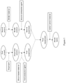
- Figure 1 depicts an embodiment of the method disclosed herein.
- a method of preparing an anode slurry comprising the steps of:
- Electrode refers to a "cathode” or an “anode”.
- positive electrode is used interchangeably with cathode.
- negative electrode is used interchangeably with anode.
- planetary mixer refers to an equipment that can be used to mix or stir different materials for producing a homogeneous mixture, which consists of blades conducting a planetary motion within a vessel.
- the planetary mixer comprises at least one planetary blade and at least one high speed dispersion blade.
- the planetary and the high speed dispersion blades rotate on their own axes and also rotate continuously around the vessel.
- the rotation speed can be expressed in unit of rotations per minute (rpm) which refers to the number of rotations that a rotating body completes in one minute.
- dispenser refers to a chemical that can be used to promote uniform and maximum separation of fine particles in a suspending medium and form a stable suspension.
- the term "dispersing” refers to an act of distributing a chemical species or a solid more or less evenly throughout a fluid.
- silicon-based material refers to a material consisting of silicon or a combination of silicon and other elements.
- conductive agent refers to a material which is chemically inactive and has good electrical conductivity. Therefore, the conductive agent is often mixed with an electrode active material at the time of forming an electrode to improve electrical conductivity of the electrode.
- homogenizer refers to an equipment that can be used for homogenization of materials.
- homogenization refers to a process of reducing a substance or material to small particles and distributing it uniformly throughout a fluid. Any conventional homogenizers can be used for the method disclosed herein. Some non-limiting examples of the homogenizer include stirring mixers, blenders, mills (e.g., colloid mills and sand mills), ultrasonicators, atomizers, rotor-stator homogenizers, and high pressure homogenizers.
- ultrasonicator refers to an equipment that can apply ultrasonic energy to agitate particles in a sample. Any ultrasonicator that can disperse the slurry disclosed herein can be used herein. Some non-limiting examples of the ultrasonicator include an ultrasonic bath, a probe-type ultrasonicator, and an ultrasonic flow cell.
- ultrasonic bath refers to an apparatus through which the ultrasonic energy is transmitted via the container's wall of the ultrasonic bath into the liquid sample.
- probe-type ultrasonicator refers to an ultrasonic probe immersed into a medium for direct sonication.
- direct sonication means that the ultrasound is directly coupled into the processing liquid.
- ultrasonic flow cell or “ultrasonic reactor chamber” refers to an apparatus through which sonication processes can be carried out in a flow-through mode.
- the ultrasonic flow cell is in a single-pass, multiple-pass or recirculating configuration.
- binder material refers to a chemical or a substance that can be used to hold the active battery electrode material and conductive agent in place.
- carbon active material refers to an active material having carbon as a main skeleton, into which lithium ions can be intercalated.
- the carbon active material include a carbonaceous material and a graphitic material.
- the carbonaceous material is a carbon material having a low degree of graphitization (low crystallinity).
- the graphitic material is a material having a high degree of crystallinity.
- particle size D50 refers to a volume-based accumulative 50% size (D50) which is a particle size at a point of 50% on an accumulative curve (i.e., a diameter of a particle in the 50th percentile (median) of the volumes of particles) when the accumulative curve is drawn so that a particle size distribution is obtained on the volume basis and the whole volume is 100%.
- D10 means a volume-based accumulative 10% size (i.e., a diameter of a particle in the 10th percentile of the volumes of particles)
- D90 means a volume-based accumulative 90% size (i.e., a diameter of a particle in the 90th percentile of the volumes of particles).
- solid content refers to the amount of non-volatile material remaining after evaporation.
- major component of a composition refers to the component that is more than 50%, more than 55%, more than 60%, more than 65%, more than 70%, more than 75%, more than 80%, more than 85%, more than 90%, or more than 95% by weight or volume, based on the total weight or volume of the composition.
- minor component of a composition refers to the component that is less than 50%, less than 45%, less than 40%, less than 35%, less than 30%, less than 25%, less than 20%, less than 15%, less than 10%, or less than 5% by weight or volume, based on the total weight or volume of the composition.
- C-rate refers to the charging or discharging rate of a cell or battery, expressed in terms of its total storage capacity in Ah or mAh. For example, a rate of 1 C means utilization of all of the stored energy in one hour; a 0.1 C means utilization of 10% of the energy in one hour or the full energy in 10 hours; and a 5C means utilization of the full energy in 12 minutes.
- ampere-hour (Ah) refers to a unit used in specifying the storage capacity of a battery.
- a battery with 1 Ah capacity can supply a current of one ampere for one hour or 0.5 A for two hours, etc. Therefore, 1 Ampere-hour (Ah) is the equivalent of 3,600 coulombs of electrical charge.
- miniampere-hour (mAh) also refers to a unit of the storage capacity of a battery and is 1/1,000 of an ampere-hour.
- milliampere-hour per gram refers to a unit specifying the specific capacity of a battery material (i.e., the capacity per unit mass of the battery material).
- battery cycle life refers to the number of complete charge/discharge cycles a battery can perform before its nominal capacity falls below 80% of its initial rated capacity.
- R R L +k ⁇ (R U -R L ), wherein k is a variable ranging from 1 percent to 100 percent with a 1 percent increment, i.e., k is 1 percent, 2 percent, 3 percent, 4 percent, 5 percent, ..., 50 percent, 51 percent, 52 percent, ..., 95 percent, 96 percent, 97 percent, 98 percent, 99 percent, or 100 percent.
- any numerical range defined by two R numbers as defined in the above is also specifically disclosed.
- a conventional method of preparing a silicon-containing anode slurry includes the steps of adding a carbon active material such as graphite particles into a binder solution to form a mixture, and then adding silicon particles and a conductive agent into the mixture to form the silicon-containing anode slurry.
- a carbon active material such as graphite particles
- silicon particles and a conductive agent into the mixture to form the silicon-containing anode slurry.
- the silicon particles tend to form aggregates which are held together by strong forces and will not easily break apart under normal dispersion conditions.
- the aggregates of the silicon particles tend to cause a problem of cracking of the silicon-containing anode during intercalation of the lithium ions.
- the present invention relates to anode slurries having improved dispersibility of a silicon-based material, an anode active material and conductive agents.
- Figure 1 shows an embodiment of the method disclosed herein.
- a dispersant solution is prepared by mixing a dispersant with a first solvent.
- a silicon-based material and a first conductive agent are then dispersed in the dispersant solution to form a first suspension.
- the first suspension is then homogenized so as to thoroughly disperse the silicon-based material and first conductive agent in the first suspension.
- a binder solution is prepared by mixing a binder material with a second solvent.
- a second conductive agent is dispersed in the binder solution to form a second suspension.
- the homogenized first suspension is then mixed with the second suspension to form a third suspension.
- a carbon active material is added to the third suspension.
- the silicon-based material, carbon active material and the conductive agents together with the binder material form a silicon-containing anode slurry.
- the method of the present invention is capable of avoiding agglomeration of nano-sized silicon-based material and effectively dispersing the nano-sized silicon-based material uniformly in anode slurries.
- a first suspension having homogeneous distribution of silicon-based material and first conductive agent is crucial to producing an anode slurry having homogeneous distribution of all the components in the anode slurry.
- preparing a second suspension having a homogeneous distribution of second conductive agent and/or carbon active material before mixing with the first suspension can ensure a homogeneous distribution of materials in the third suspension.
- the anode slurry prepared from the third suspension has a homogeneous distribution of materials.
- the first conductive agent can increase the density of an electrode coating layer.
- An anode coating layer composed of particles with different sizes can effectively increase the packing density.
- the medium size particles would fill into the voids between the larger size particles whereas the smaller size particles would fill into the voids between the medium size particles.
- This successive filling of the voids by smaller size particles would reduce the volume of voids and increase the packing density of the anode coating layer. This will accordingly increase the packing density and cell capacity.
- an anode coating layer having conductive agents with different particle size has a well-connected conductive network, thereby increasing the electrical conductivity of anode coating layer.
- anode slurry prepared by the method disclosed herein can be used to prepare an anode coating layer with increased electrical conductivity and sufficient space for the expansion of silicon-based material.
- the dispersant solution is prepared by mixing a dispersant with a first solvent.
- the dispersant is an acrylate-based or a cellulose-based polymer.
- the acrylic-based polymer include polyvinyl pyrrolidone, polyacrylic acid, and polyvinyl alcohol.
- the cellulose-based polymer include hydroxyethyl cellulose (HEC), hydroxypropyl cellulose (HPC), methyl cellulose (MC), and hydroxyalkyl methyl cellulose.
- the dispersant is selected from the group consisting of polyvinyl alcohol, polyethylene oxide, polypropylene oxide, polyvinyl pyrrolidone, polyanionic cellulose, carboxylmethyl cellulose, hydroxyethyl cellulose, carboxymethyl hydroxyethyl cellulose, methyl cellulose, starch, pectin, polyacrylamide, gelatin, polyacrylic acid, and combinations thereof.
- the use of the dispersant enhances wetting of the silicon-based material and helps the silicon-based material disperse in the dispersant solution.
- the addition of surfactants such as an anionic surfactant or a cationic surfactant tends to change other physical properties of the dispersion solution (such as surface tension), and may render the dispersion solution unsuitable for a desired application.
- the use of the dispersant may also help inhibit the settling of solid contents by increasing the viscosity of the dispersion solution. Therefore, constant viscosities in the dispersion solution and a uniform dispersion state may be retained for a long time.
- the solvent used in the anode slurry can be any polar organic solvent.
- each of the first and second solvents independently is a polar organic solvent selected from the group consisting of methyl propyl ketone, methyl isobutyl ketone, ethyl propyl ketone, diisobutyl ketone, acetophenone, N-methyl-2-pyrrolidone, acetone, tetrahydrofuran, dimethylformamide, acetonitrile, dimethyl sulfoxide, and the like.
- each of the first and second solvents independently is a solution containing water as the major component and a volatile solvent, such as alcohols, lower aliphatic ketones, lower alkyl acetates or the like, as the minor component in addition to water.
- a volatile solvent such as alcohols, lower aliphatic ketones, lower alkyl acetates or the like
- the amount of water is at least 50%, at least 55%, at least 60%, at least 65%, at least 70%, at least 75%, at least 80%, at least 85%, at least 90%, or at least 95% to the total amount of water and solvents other than water.
- the amount of water is at most 55%, at most 60%, at most 65%, at most 70%, at most 75%, at most 80%, at most 85%, at most 90%, or at most 95% to the total amount of water and solvents other than water.
- the solvent consists solely of water, that is, the proportion of water in the solvent is 100 vol.%.
- any water-miscible solvents can be used as the minor component of the first or second solvents.
- the minor component i.e., solvents other than water
- the minor component include alcohols, lower aliphatic ketones, lower alkyl acetates and combinations thereof.
- the alcohol include C 1 -C 4 alcohols, such as methanol, ethanol, isopropanol, n-propanol, butanol, and combinations thereof.
- Some non-limiting examples of the lower aliphatic ketones include acetone, dimethyl ketone, and methyl ethyl ketone.
- the lower alkyl acetates include ethyl acetate, isopropyl acetate, and propyl acetate.
- each of the first and second solvents is free of an organic solvent such as alcohols, lower aliphatic ketones, and lower alkyl acetates. Since the composition of the anode slurry does not contain any organic solvent, expensive, restrictive and complicated handling of organic solvents is avoided during the manufacture of the slurry.
- the amount of the dispersant in the dispersant solution ranges from about 0.01% to about 15%, from about 0.01% to about 10%, or from about 0.1% to about 8% by weight, based on the total weight of the dispersant solution.
- the amount of the dispersant is too high, the weight ratio of dispersant per weight of the active material is increased, and thus the amount of the active material is reduced. This results in the reduction of a cell capacity and the deterioration of cell properties.
- the viscosity of the dispersant solution is from about 10 cps to about 2,000 cps, from about 20 cps to about 1,000 cps, from about 50 cps to about 1,000 cps, from about 100 cps to about 1,000 cps, from about 200 cps to about 1,000 cps, from about 500 cps to about 1,000 cps, from about 20 cps to about 800 cps, from about 20 cps to about 500 cps, from about 20 cps to about 200 cps, from about 20 cps to about 100 cps, or from about 20 cps to about 50 cps.
- the anode slurry disclosed herein comprises a silicon-based material to increase the storage capacity of the batteries.
- a silicon-based material and a first conductive agent are dispersed in the dispersant solution to form a first suspension.
- the silicon-based material is selected from the group consisting of Si, SiO x , Si/C, SiO x /C, Si/M, and combinations thereof, wherein each x is independently from 0 to 2; M is selected from an alkali metal, an alkaline-earth metal, a transition metal, a rare earth metal, or a combination thereof, and is not Si.
- the silicon-based material can be prepared in the form of a fine powder, nano-wire, nano-rod, nano-fiber, or nano-tube. In certain embodiments, the silicon-based material is in the form of fine powder.
- the particle size of the silicon-based material is too large (e.g., larger than 800 nm), the silicon-based material will undergo a very large volume expansion, thereby causing cracking of the anode coating layer.
- the particle size of the silicon-based material is from about 10 nm to about 800 nm, from about 10 nm to about 500 nm, from about 10 nm to about 300 nm, from about 10 nm to about 100 nm, from about 30 nm to about 500 nm, from about 30 nm to about 300 nm, from about 30 nm to about 100 nm, from about 50 nm to about 300 nm, from about 50 nm to about 100 nm, or from about 100 nm to about 300 nm.
- the particle size of the silicon-based material is less than 800 nm, less than 600 nm, less than 400 nm, less than 200 nm, or less than 100 nm. In some embodiments, the particle size of the silicon-based material is greater than 10 nm, greater than 50 nm, greater than 100 nm, greater than 200 nm, or greater than 500 nm.
- the weight ratio of the silicon-based material to the dispersant in the first suspension is from about 1:1 to about 10:1, from about 1:1 to about 8:1, from about 1:1 to about 6:1, from about 3:1 to about 10:1, from about 3:1 to about 8:1,from about 3:1 to about 6:1, or from about 4:1 to about 6:1. In certain embodiments, the weight ratio of the silicon-based material to the dispersant in the first suspension is less than 10:1, less than 8:1, less than 6:1, less than 4:1, or less than 2:1. In some embodiments, the weight ratio of the silicon-based material to the dispersant in the first suspension is greater than 2:1, greater than 4:1, greater than 6:1, or greater than 8:1.
- the conductive agent in the anode slurry is for enhancing the electrically-conducting property of an anode.
- the anode slurry comprises conductive agents of different sizes.
- the anode slurry comprises a first conductive agent and a second conductive agent, and the particle size of the first conductive agent is less than the particle size of the second conductive agent.
- the first conductive agent is selected from the group consisting of carbon, carbon black, acetylene black, Super P, graphene, graphene nanoplatelets, carbon fibres, carbon nano-fibers, graphitized carbon flake, carbon tubes, carbon nanotubes, activated carbon, mesoporous carbon, and combinations thereof.
- the first conductive agent is not carbon, carbon black, acetylene black, Super P, graphene, graphene nanoplatelets, carbon fibres, carbon nano-fibers, graphitized carbon flake, carbon tubes, carbon nanotubes, activated carbon, or mesoporous carbon.
- the particle size of the first conductive agent is from about 20 nm to about 100 nm, from about 20 nm to about 80 nm, from about 30 nm to about 70 nm, from about 30 nm to about 50 nm, from about 40 nm to about 100 nm, from about 40 nm to about 60 nm, from about 45 nm to about 90 nm, from about 45 nm to about 60 nm, or from about 60 nm to about 100 nm. In some embodiments, the particle size of the first conductive agent is less than 100 nm, less than 80 nm, less than 60 nm, less than 40 nm, or less than 20 nm. In certain embodiments, the particle size of the first conductive agent is greater than 20 nm, greater than 40 nm, greater than 60 nm, or greater than 80 nm.
- the aspect ratio of each of the first conductive agent and second conductive agent is independently from about 1:1 to about 1:10, from about 1:1 to about 1:8, from about 1:1 to about 1:6, from about 1:1 to about 1:5, or from about 1:1 to about 1:3. In some embodiments, the aspect ratio of each of the first conductive agent and second conductive agent is independently less than 1:10, less than 1:8, less than 1:6, less than 1:5, or less than 1:3.
- the weight ratio of the first conductive agent to the dispersant in the first suspension is from about 0.5:1 to about 5:1, from about 0.5:1 to about 2.5:1, from about 1:1 to about 5:1, from about 1:1 to about 4:1, from about 1:1 to about 3:1, or from about 1:1 to about 2:1. In certain embodiments, the weight ratio of the first conductive agent to the dispersant in the first suspension is less than 5:1, less than 4:1, less than 3:1, less than 2:1, or less than 1:1. In some embodiments, the weight ratio of the first conductive agent to the dispersant in the first suspension is greater than 0.5:1, greater than 1:1, greater than 2:1, greater than 3:1, or greater than 4:1.
- the weight ratio of the silicon-based material to the first conductive agent is from about 2 to about 5, from about 2 to about 4, from about 2 to about 3, from about 2.5 to about 5, from about 3 to about 5, from about 3 to about 4, or from about 4 to about 5.
- the particle size distribution of the first suspension has a D10 value in a range from about 5 nm to about 100 nm, from about 5 nm to about 50 nm, from about 10 nm to about 100 nm, from about 10 nm to about 80 nm, from about 10 nm to about 60 nm, from about 10 nm to about 40 nm, from about 10 nm to about 20 nm, from about 30 nm to about 100 nm, or from about 50 nm to about 100 nm.
- the particle size distribution of the first suspension has a D50 value in a range from about 30 nm to about 1 ⁇ m, from about 30 nm to about 500 nm, from about 30 nm to about 300 nm, from about 30 nm to about 200 nm, from about 30 nm to about 100 nm, from about 30 nm to about 80 nm, from about 30 nm to about 60 nm, or from about 30 nm to about 50 nm.
- the particle size distribution of the first suspension has a D90 value in a range from about 50 nm to about 1 ⁇ m, from about 50 nm to about 800 nm, from about 50 nm to about 500 nm, from about 50 nm to about 300 nm, from about 50 nm to about 100 nm, from about 70 nm to about 300 nm, from about 70 nm to about 200 nm, from about 70 nm to about 100 nm, or from about 70 nm to about 90 nm.
- each of the D50/D10 and D90/D50 ratios of the particle size distribution of the first suspension is independently from about 0.3:1 to about 10:1, from about 1:1 to about 10:1, from about 1:1 to about 5:1, from about 1:1 to about 3:1, from about 1:1 to about 2:1,from about 2:1 to about 5:1, from about 2:1 to about 4:1, or from about 1.5:1 to about 4:1.
- each of the D50/D10 and D90/D50 ratios of the particle size distribution of the first suspension is independently less than 10:1, less than 5:1, less than 4:1, less than 3:1, less than 2:1,less than 1.5:1, or less than 1:1.
- each of the D50/D10 and D90/D50 ratios of the particle size distribution of the first suspension is independently greater than 1:1, greater than 2:1, greater than 3:1, greater than 4:1, or greater than 5:1.
- the D90/D10 ratio of the particle size distribution of the first suspension is from about 2:1 to about 10:1, from about 2:1 to about 8:1, from about 2:1 to about 6:1, from about 2:1 to about 5:1, from about 4:1 to about 10:1, from about 4:1 to about 8:1,or from about 4:1 to about 6:1. In some embodiments, the D90/D10 ratio of the particle size distribution of the first suspension is less than 10:1, less than 8:1,less than 6:1, or less than 5:1. In certain embodiments, the D90/D10 ratio of the particle size distribution of the first suspension is greater than 2:1,greater than 3:1, greater than 4:1, greater than 5:1, or greater than 6:1.
- the first suspension has a solid content from about 3% to about 35%, from about 3% to about 30%, from about 3% to about 20%, from about 3% to about 15%, from about 3% to about 10%, from about 3% to about 5%, from about 5% to about 15%, from about 5% to about 10%, from about 10% to about 35%, from about 20% to about 35%, or from about 25% to about 35% by weight, based on the total weight of the first suspension.
- the first suspension is then homogenized by a homogenizer to achieve uniform dispersion of the silicon-based material and the first conductive agent and obtain a homogenized first suspension.
- a homogenizer Any equipment that can homogenize the first suspension can be used herein.
- the homogenizer is an ultrasonicator, a stirring mixer, planetary mixer, a blender, a mill, a rotor-stator homogenizer, or a high pressure homogenizer.
- the homogenizer is an ultrasonicator. Any ultrasonicator that can apply ultrasound energy to agitate and disperse particles in a sample can be used herein.
- the ultrasonicator is an ultrasonic bath, a probe-type ultrasonicator, or an ultrasonic flow cell.
- the ultrasonicator is operated at a power density from about 20 W/L to about 200 W/L, from about 20 W/L to about 150 W/L, from about 20 W/L to about 100 W/L, from about 20 W/L to about 50 W/L, from about 50 W/L to about 200 W/L, from about 50 W/L to about 150 W/L, from about 50 W/L to about 100 W/L, from about 10 W/L to about 50 W/L, or from about 10 W/L to about 30 W/L.
- the first suspension is sonicated for a time period from about 0.5 hour to about 5 hours, from about 0.5 hour to about 3 hours, from about 0.5 hour to about 2 hours, from about 1 hour to about 5 hours, from about 1 hour to about 3 hours, from about 1 hour to about 2 hours, from about 2 hours to about 5 hours, or from about 2 hours to about 4 hours.
- the first suspension is homogenized by mechanical stirring for a time period from about 0.5 hour to about 5 hours.
- the stirring mixer is a planetary mixer consisting of planetary and high speed dispersion blades.
- the rotational speed of planetary and high speed dispersion blades is the same.
- the rotational speed of the planetary blade is from about 50 rpm to about 200 rpm and rotational speed of the dispersion blade is from about 1,000 rpm to about 3,500 rpm.
- the stirring time is from about 0.5 hour to about 5 hours, from about 1 hour to about 5 hours, from about 2 hours to about 5 hours, or from about 3 hours to about 5 hours.
- the first suspension is homogenized by mechanical stirring and ultrasonication simultaneously.
- the first suspension is ultrasonicated and stirred at room temperature for several hours.
- the combined effects of mechanical stirring and ultrasonication can enhance mixing effect.
- a homogenized first suspension could be obtained and the mixing time could be reduced.
- the time for stirring and ultrasonication is from about 0.5 hour to about 5 hours, from about 0.5 hour to about 4 hours, from about 0.5 hour to about 3 hours, from about 0.5 hour to about 2 hours, from about 0.5 hour to about 1 hour, from about 1 hour to about 4 hours, from about 1 hour to about 3 hours, or from about 1 hour to about 2 hours.
- the time for stirring and ultrasonication is at least 1 hour or 2 hours.
- ultrasonicator During the operation of ultrasonicator, ultrasound energy is converted partially into heat, causing an increase in the temperature in the suspension.
- a cooling system is used for dissipating the heat generated.
- a bath of ice In order to maintain the suspension temperature during ultrasonication, a bath of ice may be used.
- a shorter duration for ultrasonication may be used to prevent overheating the suspension due to generation of large amounts of heat.
- the suspension can also be ultrasonicated intermittently to avoid overheating. However, when a higher power is applied, considerable amount of heat can be generated due to larger oscillation amplitude. Therefore, it becomes more difficult to cool the suspension.
- the homogeneity of the silicon-based material and the first conductive agent in the first suspension depends on the ultrasound energy delivered to the suspension.
- the ultrasonic power cannot be too high as the heat generated by ultrasonication may overheat the suspension.
- a temperature rise during ultrasonication may affect the dispersion quality of particles in the first suspension.
- the ultrasonicator can be operated at a low power density to avoid overheating of the first suspension.
- the first suspension is treated by the ultrasonication at a power density of about 20 W/L to about 200 W/L with stirring at a rotational speed of the dispersion blade from about 1,000 rpm to about 3,500 rpm and rotational speed of the planetary blade from about 50 rpm to about 200 rpm.
- the ultrasonicator is operated at a power density from about 20 W/L to about 150 W/L, from about 20 W/L to about 100 W/L, from about 20 W/L to about 50 W/L, from about 50 W/L to about 200 W/L, from about 50 W/L to about 150 W/L, from about 50 W/L to about 100 W/L, from about 10 W/L to about 50 W/L, or from about 10 W/L to about 30 W/L.
- the ultrasonicator is operated at a power density less than 100 W/L, less than 80 W/L, less than 60 W/L, or less than 50 W/L. When such power densities are used, heat removal or cooling is not required for the dispersing step.
- the rotational speed of the dispersion blade is from about 1,000 rpm to about 3,000 rpm, from about 1,000 rpm to about 2,000 rpm, from about 2,000 rpm to about 3,500 rpm, or from about 3,000 rpm to about 3,500 rpm.
- the rotational speed of the planetary blade is from about 50 rpm to about 150 rpm, from about 50 rpm to about 100 rpm, from about 75 rpm to about 200 rpm, from about 75 rpm to about 150 rpm, from about 100 rpm to about 200 rpm, or from about 100 rpm to about 150 rpm.
- the first suspension prepared in the present invention shows homogeneous particle size distribution. If agglomeration of silicon-based material and first conductive agent occurs, the homogeneity of the particles in the first suspension will be affected, which will consequently affects the particle size distribution of anode slurry.
- a second suspension can be prepared by dispersing a second conductive agent in the binder solution.
- the binder material in the anode slurry performs a role of binding the active electrode material and conductive agents together on the current collector.
- a binder solution can be prepared by mixing a binder material with a second solvent.
- the binder material is selected from the group consisting of styrene-butadiene rubber (SBR), acrylated styrene-butadiene rubber, acrylonitrile copolymer, acrylonitrile-butadiene rubber, nitrile butadiene rubber, acrylonitrile-styrene-butadiene copolymer, acryl rubber, butyl rubber, fluorine rubber, polytetrafluoroethylene, polyethylene, polypropylene, ethylene/propylene copolymers, polybutadiene, polyethylene oxide, chlorosulfonated polyethylene, polyvinylpyrrolidone, polyvinylpyridine, polyvinyl alcohol, polyvinyl acetate, polyepichlorohydr
- the binder material is SBR, CMC, PAA, a salt of alginic acid, or a combination thereof.
- the binder material is acrylonitrile copolymer.
- the binder material is polyacrylonitrile.
- the binder material is free of SBR, CMC, PVDF, acrylonitrile copolymer, PAA, polyacrylonitrile, PVDF-HFP, LA132, LA133, latex, or a salt of alginic acid.
- a second suspension can be prepared by mixing a second conductive agent and a carbon active material in the second solvent.
- the second conductive agent is selected from the group consisting of carbon, conductive graphite, vapor-grown carbon fiber, KS6, KS15, expanded graphite and combinations thereof.
- the particle size of the second conductive agent is from about 1 ⁇ m to about 10 ⁇ m, from about 1 ⁇ m to about 8 ⁇ m, from about 1 ⁇ m to about 6 ⁇ m, from about 1 ⁇ m to about 4 ( ⁇ m, from about 3 ⁇ m to about 10 ⁇ m, from about 3 ⁇ m to about 8 ⁇ m, from about 3 ⁇ m to about 6 ⁇ m, from about 5 ⁇ m to about 10 ⁇ m, or from about 5 ⁇ m to about 8 ⁇ m.
- the particle size of the second conductive agent is less than 10 ⁇ m, less than 8 ⁇ m, less than 6 ⁇ m, less than 4 ⁇ m, or less than 2 ⁇ m.
- the particle size of the second conductive agent is more than 1 ⁇ m, more than 3 ⁇ m, more than 5 ⁇ m, more than 7 ⁇ m, or more than 9 ⁇ m.
- the second suspension has a solid content from about 0.5% to about 10%, from about 1% to about 10%, from about 1% to about 8%, from about 1% to about 6%, from about 1% to about 4%, from about 1% to about 2%, from about 2% to about 8%, from about 2% to about 6%, from about 2% to about 4%, or from about 5% to about 10% by weight, based on the total weight of the second suspension.
- a second suspension is prepared by mixing a second conductive agent and a carbon active material in the second solvent.
- the solid content of the second suspension is from about 15% to about 35%, from about 20% to about 35%, from about 20% to about 30%, from about 25% to about 35%, or from about 30% to about 35% by weight, based on the total weight of the second suspension.
- the time period for dispersing the second conductive agent in the binder solution is from about 0.5 hour to about 3 hours, from about 0.5 hour to about 2 hours, from about 0.5 hour to about 1 hour, from about 1 hour to about 3 hours, or from about 1 hour to about 2 hours.
- the homogenized first suspension is mixed with the second suspension to form a third suspension.
- the time period for mixing the homogenized first suspension with the second suspension is from about 0.5 hour to about 3 hours, from about 0.5 hour to about 2 hours, from about 0.5 hour to about 1 hour, from about 1 hour to about 3 hours, or from about 1 hour to about 2 hours. In some embodiments, the time period for mixing the homogenized first suspension with the second suspension is more than 0.5 hour, 0.75 hour, or more than 1 hour.
- the first suspension and the second suspension are stirred or agitated to prevent settling of the particles before the two suspensions are mixed. Therefore, the particles in suspension can be kept for extended periods of time.
- the third suspension has a solid content from about 3% to about 35%, from about 3% to about 30%, from about 3% to about 10%, from about 10% to about 35%, from about 15% to about 35%, from about 20% to about 35%, or from about 20% to about 25% by weight, based on the total weight of the third suspension.
- an anode slurry can be prepared by mixing the carbon active material with the third suspension. Mixing the homogeneous third suspension with carbon active material can prevent particle aggregation.
- the carbon active material is selected from the group consisting of hard carbon, soft carbon, graphite, mesocarbon microbeads, and combinations thereof. In other embodiments, the carbon active material is not hard carbon, soft carbon, graphite, or mesocarbon microbeads.
- an anode slurry can be prepared by mixing a binder material with the third suspension.
- the particle size of the carbon active material is from about 1 ⁇ m to about 30 ⁇ m, from about 1 ⁇ m to about 20 ⁇ m, from about 1 ⁇ m to about 10 ⁇ m, from about 10 ⁇ m to about 30 ⁇ m, from about 10 ⁇ m to about 20 ⁇ m, from about 15 ⁇ m to about 30 ⁇ m, from about 15 ⁇ m to about 25 ⁇ m, or from about 15 ⁇ m to about 20 ⁇ m.
- the particle size of the carbon active material is larger than each of the particle size of the silicon-based material, first conductive agent and second conductive agent.
- the time period for mixing the carbon active material or binder material with the third suspension is from about 0.5 hour to about 6 hours, from about 1 hour to about 6 hours, from about 1 hour to about 5 hours, from about 1 hour to about 3 hours, from about 2 hours to about 6 hours, or from about 2 hours to about 4 hours.
- the amount of the dispersant in the anode slurry is from about 0.1% to about 5%, from about 0.1% to about 2%, from about 0.5% to about 5%, from about 0.5% to about 3%, from about 0.5% to about 2%, from about 1% to about 5%, from about 1% to about 4%, or from about 1% to about 3% by weight, based on the total weight of the solid content in the anode slurry.
- the amount of the dispersant in the anode slurry is less than 10%, less than 5%, less than 4%, less than 3%, less than 2%, or less than 1% by weight, based on the total weight of solids in the anode slurry. In certain embodiments, the amount of the dispersant in the anode slurry is greater than 0.1%, greater than 0.5%, greater than 1%, greater than 2%, greater than 3%, or greater than 4% by weight, based on the total weight of the solid content in the anode slurry.
- the silicon-based material of the present invention has a content from about 1% to about 20% by weight, based on the total weight of the solid content in the anode slurry.
- the amount of the silicon-based material in the anode slurry is from about 1% to about 10%, from about 1% to about 8%, from about 1% to about 6%, from about 1% to about 4%, from about 3% to about 10%, from about 3% to about 8%, from about 5% to about 10%, from about 10% to about 20%, or from about 10% to about 15% by weight, based on the total weight of the solid content in the anode slurry.
- the amount of the silicon-based material in the anode slurry is less than 20%, less than 15%, less than 10%, less than 5%, less than 4%, less than 3%, less than 2%, or less than 1% by weight, based on the total weight of the solid content in the anode slurry.
- the content of the silicon-based material in the anode slurry is at most 1%, at most 2%, at most 3%, at most 4%, at most 5%, at most 10%, at most 15%, or at most 20% by weight, based on the total weight of the solid content in the anode slurry.
- the first conductive agent having small particle size can be used to fill the void between larger electrode material particles to increase the packing density and electrical conductivity of an anode.
- the ratio of the particle size of the second conductive agent to the particle size of the first conductive agent is from about 20:1 to about 250:1, from about 20:1 to about 200:1, from about 20:1 to about 150:1, from about 20:1 to about 100:1, from about 20:1 to about 50:1, from about 50:1 to about 250:1, from about 50:1 to about 150:1, from about 50:1 to about 200:1, or from about 100:1 to about 250:1.
- the ratio of the particle size of the second conductive agent to the particle size of the first conductive agent is less than 300:1, less than 250:1, less than 200:1, less than 150:1, less than 100:1, or less than 50:1. In certain embodiments, the ratio of the particle size of the second conductive agent to the particle size of the first conductive agent is greater than 10:1, greater than 20:1, greater than 50:1, greater than 100:1, or greater than 150:1.
- the amount of each of the first and second conductive agents in the anode slurry is independently at least 0.1%, at least 0.5%, at least 1%, at least 1.5%, at least 2%, at least 2.5%, at least 3%, at least 3.5%, at least 4%, at least 4.5%, at least 5%, at least 6%, or at least 7% by weight, based on the total weight of the solid content in the anode slurry.
- the amount of each of the first and second conductive agents in the anode slurry is independently at most 10%, at most 9%, at most 8%, at most 7%, at most 6%, at most 5%, at most 4.5%, at most 4%, or at most 3.5% by weight, based on the total weight of the solid content in the anode slurry.
- the amount of each of the first and second conductive agents in the anode slurry is independently from about 0.5% to about 10%, from about 0.5% to about 5%, from about 1% to about 10%, from about 1% to about 8%, from about 1% to about 6%, from about 1% to about 5%, from about 1% to about 4%, from about 3% to about 7%, or from about 3% to about 5% by weight, based on the total weight of the solid content in the anode slurry.
- the total amount of the first conductive agent and second conductive agent in the anode slurry is from about 0.1% to about 10%, from about 0.5% to about 10%, from about 0.5% to about 8%, from about 0.5% to about 5%, from about 1% to about 7%, from about 1% to about 5%, from about 3% to about 8%, or from about 3% to about 5% by weight, based on the total weight of the solid content in the anode slurry.
- the total amount of the first conductive agent and second conductive agent in the anode slurry is at least 0.1%, at least 0.5%, at least 1%, at least 2%, at least 3%, at least 4%, or at least 5% by weight, based on the total weight of the solid content in the anode slurry.
- the weight ratio of the first conductive agent to the second conductive agent in the anode slurry is from about 1:1 to about 2:1, from about 1:1 to about 1.8:1, from about 1:1 to about 1.6:1, from about 1:1 to about 1.5:1, from about 1:1 to about 1.3:1, from about 1:1 to about 1.1:1, from about 1.2:1 to about 1.8:1, from about 1.3:1 to about 1.7:1, or from about 1.5:1 to about 2:1.
- the weight ratio of the first conductive agent to the second conductive agent in the anode slurry is less than 3:1, less than 2.5:1, less than 2:1, or less than 1.5:1.
- the weight ratio of the first conductive agent to the second conductive agent in the anode slurry is greater than 0.5:1, greater than 1:1, or greater than 1.5:1.
- the weight ratio of the silicon-based material to the first conductive agent is from about 1.7:1 to about 5:1, from about 1.7:1 to about 4:1, from about 1.7:1 to about 3:1, from about 2:1 to about 5:1, from about 2:1 to about 4:1, from about 2:1 to about 3:1, or from about 3:1 to about 5:1. In certain embodiments, the weight ratio of the silicon-based material to the first conductive agent is less than 2.5:1, less than 3:1, less than 3.5:1, less than 4:1, or less than 4.5:1. In certain embodiments, the weight ratio of the silicon-based material to the first conductive agent is greater than 1.7:1, greater than 2:1, greater than 2.5:1, greater than 3:1, greater than 3.5:1, greater than 4:1, or greater than 4.5:1.
- the amount of the binder material in the anode slurry is at least 0.1%, at least 0.5%, at least 1%, at least 2%, at least 3%, at least 4%, at least 5%, or at least 10% by weight, based on the total weight of the solid content in the anode slurry. In some embodiments, the amount of the binder material in the anode slurry is at most 0.1%, at most 0.5%, at most 1%, at most 2%, at most 3%, at most 4%, at most 5%, or at most 10% by weight, based on the total weight of the solid content in the anode slurry.
- the amount of the binder material in the anode slurry is from about 0.1% to about 5%, from about 0.1% to about 2%, from about 0.1% to about 1%, from about 1% to about 10%, from about 1% to about 5%, from about 3% to about 10%, or from about 5% to about 10% by weight, based on the total weight of the solid content in the anode slurry.
- the resulting anode slurry may contain up to 50% or 60% dispersed solids by weight, based on total weight of the anode slurry.
- the anode slurry has a solid content from about 25% to about 65%, from about 30% to about 65%, from about 30% to about 60%, from about 30% to about 55%, from about 30% to about 50%, from about 35% to about 60%, from about 35% to about 50%, or from about 40% to about 55% by weight, based on the total weight of the anode slurry.
- the mixing or dispersing of anode slurry can be carried out by a stirring mixer, a blender, a mill, a rotor-stator homogenizer, or a high pressure homogenizer.
- the stirring mixer is a planetary stirrer.
- the rotational speed of planetary and high speed dispersion blades is the same. In other embodiments, the rotational speed of the planetary blade is from about 50 rpm to about 200 rpm and rotational speed of the dispersion blade is from about 1,000 rpm to about 3,500 rpm.
- D10 of the particles in the anode slurry is from about 0.5 ⁇ m to about 10 ⁇ m, from about 1 ⁇ m to about 10 ⁇ m, from about 1 ⁇ m to about 8 ⁇ m, from about 1 ⁇ m to about 6 ⁇ m, from about 3 ⁇ m to about 10 ⁇ m, from about 3 ⁇ m to about 8 ⁇ m, from about 3 ⁇ m to about 6 ⁇ m, or from about 4 ⁇ m to about 6 ⁇ m.
- D50 of the particles in the anode slurry is from about 1 ⁇ m to about 25 ⁇ m, from about 5 ⁇ m to about 25 ⁇ m, from about 5 ⁇ m to about 20 ⁇ m, from about 10 ⁇ m to about 25 ⁇ m, from about 10 ⁇ m to about 20 ⁇ m, from about 10 ⁇ m to about 18 ⁇ m, from about 12 ⁇ m to about 18 ⁇ m, or from about 14 ⁇ m to about 16 ⁇ m.
- D90 of the particles in the anode slurry is from about 5 ⁇ m to about 40 ⁇ m, from about 10 ⁇ m to about 40 ⁇ m, from about 10 ⁇ m to about 30 ⁇ m, from about 20 ⁇ m to about 40 ⁇ m, from about 20 ⁇ m to about 35 ⁇ m, from about 20 ⁇ m to about 30 ⁇ m, from about 20 ⁇ m to about 28 ⁇ m, from about 20 ⁇ m to about 26 ⁇ m, or from about 25 ⁇ m to about 30 ⁇ m.
- Viscosity control is essential to a coating process.
- the viscosity of the anode slurry is from about 1,000 cps to about 10,000 cps, from about 1,000 cps to about 8,000 cps, from about 1,000 cps to about 6,000 cps, from about 1,000 cps to about 3,000 cps, from about 2,000 cps to about 8,000 cps, from about 2,000 cps to about 6,000 cps, from about 3,000 cps to about 8,000 cps, from about 3,000 cps to about 6,000 cps, from about 3,000 cps to about 6,000 cps, from about 3,000 cps to about 5,000 cps, or from about 4,000 cps to about 6,000 cps.
- the viscosity of the anode slurry disclosed herein is stabilized. Constant viscosities in different parts of the anode slurry and a uniform dispersion state in the anode slurry can be retained for a long time. Uniform distributions of the active material and the conductive agents over the whole surfaces of the electrode can be obtained by coating the anode slurry on the anode current collector.
- a dispersant solution was prepared by dissolving 0.1 kg of polyvinyl alcohol (PVA; obtained from Aladdin Industries Corporation, China) in 2 L deionized water.
- the dispersant solution had a viscosity of 20 cP.
- a first suspension was then prepared by dispersing 0.5 kg of silicon having a particle size of 50 nm (obtained from CWNANO Co. Ltd., China) and 0.2 kg of acetylene black (obtained from Timcal Ltd., Bodio, Switzerland) having a particle size of 50 nm in the dispersant solution.
- the first suspension had a solid content of 28.6 wt.%.
- the first suspension was ultrasonicated by a 30 L ultrasonicator (G-100ST; obtained from Shenzhen Geneng Cleaning Equipment Co. Ltd., China) at a power density of 20 W/L and stirred by a 5 L planetary mixer (CM05, obtained from ChienMei Co. Ltd., China) simultaneously at 25 °C for about 2 hours to obtain a homogenized first suspension.
- the stirring speed of the planetary blade was 40 rpm and the stirring speed of the dispersion blade was 2,500 rpm.
- a binder solution was prepared by mixing 0.2 kg of polyacrylic acid (PAA, #181285, obtained from Sigma-Aldrich, US) with 20 L deionized water.
- a second suspension was prepared by dispersing 0.1 kg of KS15 (obtained from Timcal Ltd., Bodio, Switzerland) having a particle size of 5 ⁇ m in the binder solution with a 30 L planetary mixer (CM30; obtained from ChienMei Co. Ltd., China) for 1 hour to obtain a second suspension having a solid content of 1.5 wt.%.
- the stirring speed of the planetary blade was 40 rpm and the stirring speed of the dispersion blade was 2,500 rpm.
- a third suspension was prepared by mixing the homogenized first suspension with the second suspension with a 30 L planetary mixer for 1 hour.
- the suspension had a solid content of 4.8 wt.%.
- the stirring speed of the planetary blade was 40 rpm and the stirring speed of the dispersion blade was 2,500 rpm.
- An anode slurry was prepared by mixing 8.9 kg of graphite (#282863, obtained from Sigma-Aldrich, US) having a particle size of 15 ⁇ m with the third suspension with a 30 L planetary mixer for 1 hour.
- the anode slurry had a solid content of 31.3 wt.%.
- the stirring speed of the planetary blade was 40 rpm and the stirring speed of the dispersion blade was 2,500 rpm.
- Particle size distributions of the first suspension and the anode slurry were measured by a laser diffraction particle size distribution analyzer (Mastersizer 3000, Malvern Instruments Ltd., UK). Samples were delivered to the measurement area of the optical bench in a stable state of dispersion. The measurement of particle sizes was carried out while the particles were sufficiently dispersed.
- a negative electrode was prepared by coating the anode slurry onto one side of a copper foil having a thickness of 9 ⁇ m using a doctor blade coater (obtained from Shenzhen KejingStar Technology Ltd., China; model no. MSK-AFA-III) with an area density of about 8 mg/cm 2 .
- the coated film on the copper foil was dried by an electrically heated conveyor oven set at 90 °C for 2 hours.
- the coated anode sheet was cut into disc-form negative electrodes for coin cell assembly.
- a lithium metal foil having a thickness of 500 ⁇ m was used as a counter electrode.
- the electrolyte was a solution of LiPF 6 (1 M) in a mixture of ethylene carbonate (EC), ethyl methyl carbonate (EMC) and dimethyl carbonate (DMC) in a volume ratio of 1:1:1.
- EC ethylene carbonate
- EMC ethyl methyl carbonate
- DMC dimethyl carbonate
- Three CR2032 coin cells were assembled in an argon-filled glove box.
- the anode slurry prepared above was coated onto both sides of a copper foil having a thickness of 9 ⁇ m using a transfer coater with an area density of about 15 mg/cm 2 .
- the coated films on the copper foil were dried at about 50 °C for 2.4 minutes by a 24-meter-long conveyor hot air dryer operated at a conveyor speed of about 10 meters/minute to obtain an anode.
- a cathode slurry was prepared by mixing 92 wt.% LiMn 2 O 4 cathode active material (obtained from HuaGuan HengYuan LiTech Co. Ltd., Qingdao, China), 4 wt.% carbon black (SuperP; obtained from Timcal Ltd, Bodio, Switzerland) as a conductive agent, and 4 wt.% polyvinylidene fluoride (PVDF; Solef ® 5130, obtained from Solvay S.A., Belgium) as a binder, which were dispersed in a mixed solvent containing 50 wt.% N-methyl-2-pyrrolidone (NMP; purity of ⁇ 99%, Sigma-Aldrich, USA) and 50 wt.% acetone (purity of ⁇ 99%, Sigma-Aldrich, USA) to form a slurry with a solid content of 50 wt.%.
- the slurry was homogenized by a planetary stirring mixer.
- the homogenized slurry was coated onto both sides of an aluminum foil having a thickness of 20 ⁇ m as a current collector using a doctor blade coater with a gap width of 100 ⁇ m.
- the coated film on the aluminum foil was dried by an electrically heated conveyor oven at 85 °C at a conveyor speed of about 8 meters/minute to obtain a cathode.
- cathode film and anode film were used to prepare the cathode and anode respectively by cutting them into individual electrode plates.
- a pouch cell was assembled by stacking the cathode and anode electrode plates alternatively and then packaged in a case made of an aluminum-plastic laminated film. The cathode and anode electrode plates were kept apart by separators and the case was pre-formed. An electrolyte was then filled into the case holding the packed electrodes in high-purity argon atmosphere with moisture and oxygen content less than 1 ppm.
- the electrolyte was a solution of LiPF 6 (1 M) in a mixture of ethylene carbonate (EC), ethyl methyl carbonate (EMC) and dimethyl carbonate (DMC) in a volume ratio of 1:1:1. After electrolyte filling, the pouch cell was vacuum sealed and then mechanically pressed using a punch tooling with standard square shape.
- EC ethylene carbonate
- EMC ethyl methyl carbonate
- DMC dimethyl carbonate
- the discharging rate performance of the coin cells prepared above was evaluated.
- the coin cells were analyzed in a constant current mode using a multi-channel battery tester (BTS-4008-5V10mA, obtained from Neware Electronics Co. Ltd., China). After an initial activation process at C/10 for 1 cycle, the cells were fully charged at a rate of C/10 and then discharged at a rate of C/10. This procedure was repeated by discharging the fully charged battery module at various C-rates (1C, 3C and 5C) to evaluate the discharging rate performance.
- the voltage range was between 0.005 V and 1.5 V.
- the cyclability performance of the pouch cell was tested by charging and discharging at a constant current rate of 1C between 3.0 V and 4.2 V.
- a dispersant solution was prepared by dissolving 0.1 kg of polyvinyl alcohol (PVA; obtained from Aladdin Industries Corporation, China) in 2 L N-methyl-2-pyrrolidone (NMP; purity of ⁇ 99%, Sigma-Aldrich, USA).
- the dispersant solution had a viscosity of 20 cP.
- a first suspension was then prepared by dispersing 0.5 kg of silicon carbon composite having a particle size of 50 nm (Si/C; obtained from CWNANO Co. Ltd., China) and 0.2 kg of acetylene black (obtained from Timcal Ltd., Bodio, Switzerland) having a particle size of 50 nm in the dispersant solution.
- the first suspension had a solid content of 28.6 wt.%.
- the first suspension was ultrasonicated by a 30 L ultrasonicator at a power density of 20 W/L and stirred by a 5 L planetary mixer simultaneously at 25 °C for about 2 hours to obtain a homogenized first suspension.
- the stirring speed of the planetary blade was 40 rpm and the stirring speed of the dispersion blade was 2,500 rpm.
- a binder solution was prepared by mixing 0.2 kg of polyvinylidene fluroide (PVDF; #181285, obtained from Sigma-Aldrich, US) with 20 L N-methyl-2-pyrrolidone (NMP; purity of ⁇ 99%, Sigma-Aldrich, US).
- a second suspension was prepared by dispersing 0.1 kg of KS15 (obtained from Timcal Ltd., Bodio, Switzerland) having a particle size of 5 ⁇ m (obtained from Timcal Ltd., Bodio, Switzerland) in the binder solution with a 30 L planetary mixer for 1 hour to obtain a second suspension having a solid content of 1.5 wt.%.
- the stirring speed of the planetary blade was 40 rpm and the stirring speed of the dispersion blade was 2,500 rpm.
- a third suspension was prepared by mixing the homogenized first suspension with the second suspension with a 30 L planetary mixer for 1 hour.
- the suspension had a solid content of 4.8 wt.%.
- the stirring speed of the planetary blade was 40 rpm and the stirring speed of the dispersion blade was 2,500 rpm.
- An anode slurry was prepared by mixing 8.9 kg of graphite (#282863, obtained from Sigma-Aldrich, US) having a particle size of 15 ⁇ m with the third suspension with a 30 L planetary mixer for 1 hour.
- the anode slurry had a solid content of 31.3 wt.%.
- the stirring speed of the planetary blade was 40 rpm and the stirring speed of the dispersion blade was 2,500 rpm.
- a dispersant solution was prepared by dissolving 0.1 kg of polyethylene oxide (PEO; #181986, obtained from Sigma-Aldrich, US) in 2 L deionized water.
- the dispersant solution had a viscosity of 20 cP.
- a first suspension was then prepared by dispersing 0.5 kg of silicon carbon composite having a particle size of 50 nm (Si/C; obtained from CWNANO Co. Ltd., China) and 0.2 kg of Super P (super P; obtained from Timcal Ltd., Bodio, Switzerland) having a particle size of 50 nm in the dispersant solution.
- the first suspension had a solid content of 28.6 wt.%.
- the first suspension was ultrasonicated by a 30 L ultrasonicator at a power density of 20 W/L and stirred by a 5 L planetary mixer simultaneously at 25 °C for about 2 hours to obtain a homogenized first suspension.
- the stirring speed of the planetary blade was 40 rpm and the stirring speed of the dispersion blade was 2,500 rpm.
- a binder solution was prepared by mixing 0.2 kg of polyacrylic acid (PAA, #181285, obtained from Sigma-Aldrich, US) with 20 L deionized water.
- a second suspension was prepared by dispersing 0.1 kg of KS6 (obtained from Timcal Ltd., Bodio, Switzerland) having a particle size of 5 ⁇ m in the binder solution with a 30 L planetary mixer for 1 hour to obtain a second suspension having a solid content of 1.5 wt.%.
- the stirring speed of the planetary blade was 40 rpm and the stirring speed of the dispersion blade was 2,500 rpm.
- a third suspension was prepared by mixing the homogenized first suspension with the second suspension with a 30 L planetary mixer for 1 hour.
- the suspension had a solid content of 4.8 wt.%.
- the stirring speed of the planetary blade was 40 rpm and the stirring speed of the dispersion blade was 2,500 rpm.
- An anode slurry was prepared by mixing 8.9 kg of graphite (#282863, obtained from Sigma-Aldrich, US) having a particle size of 15 ⁇ m with the third suspension with a 30 L planetary mixer for 1 hour.
- the anode slurry had a solid content of 31.3 wt.%.
- the stirring speed of the planetary blade was 40 rpm and the stirring speed of the dispersion blade was 2,500 rpm.
- a dispersant solution was prepared by dissolving 0.1 kg of carboxymethyl cellulose (CMC; BSH-12; DKS Co. Ltd., Japan) in 2 L deionized water.
- the dispersant solution had a viscosity of 20 cP.
- a first suspension was then prepared by dispersing 0.5 kg of silicon carbon composite having a particle size of 50 nm (Si/C; obtained from CWNANO Co. Ltd., China) and 0.2 kg of Super P (obtained from Timcal Ltd., Bodio, Switzerland) having a particle size of 50 nm in the dispersant solution.
- the first suspension had a solid content of 28.6 wt.%.
- the first suspension was ultrasonicated by a 30 L ultrasonicator at a power density of 20 W/L and stirred by a 5 L planetary mixer simultaneously at 25 °C for about 2 hours to obtain a homogenized first suspension.
- the stirring speed of the planetary blade was 40 rpm and the stirring speed of the dispersion blade was 2,500 rpm.
- a second suspension was prepared by mixing 0.1 kg of KS6 (obtained from Timcal Ltd., Bodio, Switzerland) having a particle size of 5 ⁇ m with 8.9 kg of graphite (#282863, obtained from Sigma-Aldrich, US) having a particle size of 15 ⁇ m with a 30 L planetary mixer for 1 hour in 20 L deionized water.
- the second suspension had a solid content of 30.8 wt.%.
- the stirring speed of the planetary blade was 40 rpm and the stirring speed of the dispersion blade was 2,500 rpm.
- a third suspension was prepared by mixing the homogenized first suspension with the second suspension with a 30 L planetary mixer for 1 hour.
- the suspension had a solid content of 30.8 wt.%.
- the stirring speed of the planetary blade was 40 rpm and the stirring speed of the dispersion blade was 2,500 rpm.
- An anode slurry was prepared by mixing 0.2 kg of styrene-butadiene rubber (SBR; AL-2001; NIPPON A&L INC., Japan) with the third suspension with a 30 L planetary mixer for 1 hour.
- the anode slurry had a solid content of 31.3 wt.%.
- the stirring speed of the planetary blade was 40 rpm and the stirring speed of the dispersion blade was 2,500 rpm.
- An anode slurry was prepared by the method described in Example 1 except that the first conductive agent having a particle size of 20 nm instead of 50 nm was used.
- An anode slurry was prepared by the method described in Example 1 except that the first conductive agent having a particle size of 100 nm instead of 50 nm was used.
- An anode slurry was prepared by the method described in Example 1 except that the second conductive agent having a particle size of 1 ⁇ m instead of 5 ⁇ m was used.
- An anode slurry was prepared by the method described in Example 1 except that the second conductive agent having a particle size of 10 ⁇ m instead of 5 ⁇ m was used.
- An anode slurry was prepared by the method described in Example 1 except that the silicon-based material having a particle size of 10 nm instead of 50 nm was used.
- An anode slurry was prepared by the method described in Example 1 except that the silicon-based material having a particle size of 800 nm instead of 50 nm was used.
- An anode slurry was prepared by the method described in Example 1 except that 0.1 kg of first conductive agent instead of 0.2 kg was used.
- An anode slurry was prepared by the method described in Example 1 except that 6 L of deionized water was used to prepare a dispersant solution instead of 2 L, 16 L of deionized water was used to prepare a binder solution instead of 20 L, and different weight ratio of electrode materials were used.
- An anode slurry was prepared by the method described in Example 1 except that a dispersant solution was not prepared, and the silicon-based material and first conductive agent were dispersed in deionized water to form a first suspension.
- An anode slurry was prepared by the method described in Example 3 except that the second conductive agent was added in the first solvent instead of the second solvent.
- a first suspension was prepared by dispersing the silicon-based material, the first and second conductive agents in the dispersant solution.
- An anode slurry was prepared by the method described in Example 3 except that the first conductive agent was added in the second solvent instead of the first solvent.
- a second suspension was prepared by dispersing the first and second conductive agents in the binder solution.
- An anode slurry was prepared by the method described in Example 3 except that a second conductive agent was not added when preparing the second suspension and 0.3 kg of first conductive agent was used instead of 0.2 kg.
- An anode slurry was prepared by the method described in Example 1 except that a first conductive agent was not added when preparing the first suspension and 0.3 kg of second conductive agent was used instead of 0.1 kg.
- An anode slurry was prepared by the method described in Example 1 except that the first conductive agent having a particle size of 5 nm instead of 50 nm was used.
- An anode slurry was prepared by the method described in Example 1 except that the first conductive agent having a particle size of 300 nm instead of 50 nm was used.
- An anode slurry was prepared by the method described in Example 1 except that the second conductive agent having a particle size of 0.7 ⁇ m instead of 5 ⁇ m was used.
- An anode slurry was prepared by the method described in Example 1 except that the second conductive agent having a particle size of 15 ⁇ m instead of 5 ⁇ m was used.
- An anode slurry was prepared by the method described in Example 1 except that the silicon-based material having a particle size of 1 nm instead of 50 nm was used.
- An anode slurry was prepared by the method described in Example 1 except that the silicon-based material having a particle size of 1 ⁇ m instead of 50 nm was used.
- An anode slurry was prepared by the method described in Example 1 except that 1 kg of first conductive agent was used instead of 0.2 kg.
- An anode slurry was prepared by the method described in Example 1 except that 0.4 kg of second conductive agent was used instead of 0.1 kg.
- Electrochemical performance of coin cells and pouch cells were measured by the method described in Example 1.
- the formulations of the dispersant solutions and first suspensions of Examples 1-3, 5-12 and Comparative Examples 1,4-13 are shown in Table 1 below.
- the formulations of the second suspensions and anode slurries of Examples 1-3, 5-12 and Comparative Examples 1, 4-13 are shown in Table 2 below.
- the particle size distributions of the first suspensions and the anode slurries of Examples 1-12 and Comparative Examples 1-13 are shown in Table 3 below.
- the discharging rate performance of coin cells and cyclability performance of pouch cells of Examples 1-12 and Comparative Examples 1-13 are shown in Table 4 and 5 below respectively.
- the anode slurries prepared by methods described in Examples 1-12 yielded a more controlled particle size distributions.
- the coin cells of Examples 1-12 showed excellent rate performance at low and high discharge rates. Also, the pouch cells of Examples 1-12 showed excellent cyclability.
- Table 1 Amount of materials used (kg) Dispersant solution First suspension Solvent used in dispersant solution and first suspension Dispersant Si-based material 1 st conductive agent Dispersant Wt.% of dispersant Particle size (nm) Wt.% of components Si-based material 1 st conductive agent Si-based material 1 st conductive agent
- Example 1 0.1 0.5 0.2 PVA 4.8 50 50 50 3.6 17.9 7.1 Water
- Example 2 0.1 0.5 0.2 PVA 4.8 50 50 50 3.6 17.9 7.1
- NMP Example 3 0.1 0.5 0.2 PEO 4.8 50 50 3.6 17.9 7.1
- Water Example 5 0.1 0.5 0.2 PVA 4.8 50 20 3.6 17.9 7.1 Water
- Example 6 0.1
- Example 1 0.1 0.2 8.9 5 0.49 0.99 15 27.8 100 2
- Example 2 0.1 0.2 8.9 5 0.49 0.99 15 27.8 100 2
- Example 3 0.1 0.2 8.9 5 0.49 0.99 15 27.8 100 2
- Example 5 0.1 0.2 8.9 5 0.49 0.99 15 27.8 250 2
- Example 6 0.1 0.2 8.9 5 0.49 0.99 15 27.8 50 2
- Example 7 0.1 0.2 8.9 1 0.49 0.99 15 27.8 20 2
- Example 8 0.1 0.2 8.9 10 0.49 0.99 15 27.8 200 2
- Example 9 0.1 0.2 8.9 5 0.49 0.99 15 27.8 100 2
- Example 10 0.1 0.2 8.9 5 0.49 0.99 15 27.8 100 2
- Example 11 0.1 0.2 8.9 5 0.49 0.99 15 27.9 100 1
- Example 12 0.3 0.4 6.9 5 1.80 2.40 15 21.6 100 2 Comparative Example 1 0.1 0.2 8.9 5 0.49 0.99 15 27.8 100 2
- Example 12
Description
- The present invention relates to the field of batteries. In particular, this invention relates to methods for preparing anode slurries of lithium-ion batteries.
- Lithium-ion batteries (LIBs) have attracted extensive attention in the past two decades for a wide range of applications in portable electronic devices such as cellular phones and laptop computers. Due to rapid market development of electric vehicles (EV) and grid energy storage, high-performance, low-cost LIBs are currently offering one of the most promising options for large-scale energy storage devices.
- Characteristics of electrodes can dramatically affect performance and safety characteristics of a battery. An anode of a conventional lithium-ion battery mainly includes a carbon-based anode material, such as mesocarbon microbeads and artificial graphite. The storage capacity of conventional lithium-ion batteries is limited since the full specific capacity of a carbon-based anode material has a theoretical value of 372 mAh/g. Compared to the carbon-based anode material, a silicon-containing anode material has a high theoretical specific capacity of about 4,000 mAh/g.
- However, silicon-based anodes suffer from poor cycle life. During charge and discharge of the lithium-ion battery, lithium ions undergo intercalation and de-intercalation on the silicon-containing anode material, which results in volumetric expansion and contraction of the silicon-containing anode material. The resulting stresses tend to cause cracking in the anode layer, which in turn causes the anode materials to fall away from the electrode and a decrease in the service life of the lithium-ion battery. The cracking problem becomes more severe when aggregates of silicon particles are present in the anode. Therefore, preparation of the anode slurries is an essential first step towards the production of good quality batteries.
-
CN Patent Application Publication No. 104617280 A discloses an adhesive-free graphene/silicon electrode. The electrode is prepared by adding silicon powder and a surfactant to deionized water to obtain a mixture; dispersing the mixture by ultrasonication; adding graphene colloid to the mixture; dispersing the mixture by ultrasonication to obtain a slurry; and coating the slurry onto a copper foil. However, the method is complicated as it involves steps of introducing functional groups to graphene and the surface of the copper foil. -
CN Patent Application Publication No. 105336937 A discloses an anode slurry for lithium-ion batteries and a preparation method thereof. The method comprises adding nano-silicon powder to ethylene glycol to obtain a dispersing solution; homogenizing the dispersing solution by ultrasonication; adding a binder, graphite powder and conductive agent to a solvent to obtain a mixed slurry; adding the dispersing solution in several portions to the mixed slurry; and homogenizing the mixture to obtain the anode slurry. However, this method is complicated and time consuming because it involves cooling the dispersing solution during ultrasonication to prevent overheating and portionwise addition of the dispersing solution to the mixed slurry. -
CN Patent Application Publication No. 104282881 A discloses an anode and a preparation method thereof. The method comprises preparing a binder solution by dissolving polyimide in an organic solvent comprising at least one solvent selected from N-methyl-2-pyrrolidone (NMP), dimethylacetamide (DMAC), and dimethylformamide (DMF); adding a conductive agent to the binder solution to obtain a conductive liquid; adding a silicon anode material to the conductive liquid to form a mixture; and adding a carbon material and NMP to the mixture to obtain a slurry. However, this method is not suitable for application to binders other than polyimide. -
CN Patent Application Publication No. 105304858 A discloses a negative electrode and a method to prepare the same. The method comprises adding a silicon-based material, a first conductive agent and a first binder to deionised water and mixing thoroughly; adjusting the pH to less than 7; heating the mixture while mixing to allow its solid content to reach a predetermined value to obtain a first slurry; mixing a carbon-based material, a second conductive agent and a second binder in deionized water to obtain a second slurry; and mixing the first and second slurries together. However, this method does not include a way of preventing aggregation of the silicon-based material. -
CN Patent Application Publication No. 104752696 A discloses a graphene-based silicon-carbon composite anode material and a method to prepare the same. The method comprises dispersing graphene in a solvent to form a graphene suspension; dispersing silicon powder in a solvent and adding a silane coupling agent; dispersing ultrasonically then stirring magnetically to obtain a silicon powder suspension; mixing the two suspensions together; adding graphite and mixing thoroughly; and drying, grinding and sieving to obtain the composite anode material. However, the method does not provide a way of securing uniform dispersion of slurry components. -
JP Patent Application Publication No. 2015-53152 A - An anode slurry containing a uniformly dispersed silicon-based material would be highly desirable for battery performance. In view of the above, there is a need for a continuous improvement of the methods for preparing anode slurries containing uniformly dispersed silicon-based material.
- The aforementioned needs are met by the invention as defined in the appended claims and embodiments disclosed herein.
- In one aspect, provided herein is a method of preparing an anode slurry, comprising the steps of:
- 1) mixing a dispersant with a first solvent to form a dispersant solution;
- 2) dispersing a silicon-based material and a first conductive agent in the dispersant solution to form a first suspension;
- 3) homogenizing the first suspension by a homogenizer to obtain a homogenized first suspension;
- 4) mixing a binder material with a second solvent to form a binder solution;
- 5) dispersing a second conductive agent in the binder solution to form a second suspension;
- 6) mixing the homogenized first suspension with the second suspension to form a third suspension; and
- 7) mixing a carbon active material with the third suspension to form the anode slurry;
- In some embodiments, the dispersant is selected from the group consisting of polyvinyl alcohol, polyethylene oxide, polypropylene oxide, polyvinyl pyrrolidone, polyanionic cellulose, carboxylmethyl cellulose, hydroxyethylcellulose, carboxymethyl hydroxyethyl cellulose, methyl cellulose, starch, pectin, polyacrylamide, gelatin, polyacrylic acid, and combinations thereof. In certain embodiments, the viscosity of the dispersant solution is from about 10 cps to about 2,000 cps.
- In certain embodiments, each of the first and second solvents is independently selected from the group consisting of water, ethanol, isopropanol, methanol, acetone, n-propanol, t-butanol, N-methyl-2-pyrrolidone, and combinations thereof.
- In some embodiments, the silicon-based material is selected from the group consisting of Si, SiOx, Si/C, SiOx/C, Si/M, and combinations thereof, wherein each x is independently from 0 to 2; M is selected from an alkali metal, an alkaline-earth metal, a transition metal, a rare earth metal, or a combination thereof, and is not Si. In some embodiments, the particle size of the silicon-based material is from about 10 nm to about 800 nm.
- In certain embodiments, the first conductive agent is selected from the group consisting of carbon, carbon black, acetylene black, Super P, graphene, graphene nanoplatelets, carbon fibres, carbon nano-fibers, graphitized carbon flake, carbon tubes, carbon nanotubes, activated carbon, mesoporous carbon, and combinations thereof. In certain embodiments, the particle size of the first conductive agent is from about 20 nm to about 100 nm.
- In some embodiments, the particle size distribution of the first suspension has a D10 value in a range from about 10 nm to about 100 nm, a D50 value in a range from about 30 nm to about 2 µm, and a D90 value in a range from about 70 nm to about 3 µm.
- In certain embodiments, the D90/D50 ratio of the particle size distribution is less than 2:1.
- In some embodiments, the second conductive agent is selected from the group consisting of carbon, conductive graphite, vapor-grown carbon fiber, KS6, KS15, expanded graphite and combinations thereof. In certain embodiments, the particle size of the second conductive agent is from about 1 µm to about 10 µm. In some embodiments, the weight ratio of the first conductive agent to the second conductive agent is from about 5:1 to about 1:1.
- In some embodiments, the carbon active material is selected from the group consisting of hard carbon, soft carbon, graphite, mesocarbon microbeads, and combinations thereof. In certain embodiments, the particle size of the carbon active material is from about 1 µm to about 20 µm.
- In certain embodiments, the ratio of the particle size of the second conductive agent to particle size of the first conductive agent is from about 20:1 to about 250:1.
- In some embodiments, the weight ratio of the silicon-based material to the first conductive agent is from about 1.7:1 to about 5:1.
- In certain embodiments, the weight ratio of the first conductive agent to the second conductive agent is from about 1:1 to about 2:1.
- In some embodiments, the amount of the silicon-based material is from about 1% to about 20% by weight, based on the total weight of the solid content in the anode slurry.
- In certain embodiments, the amount of the first conductive agent and second conductive agent in the anode slurry is greater than or equal to 3% by weight, based on the total weight of solid content in the anode slurry.
- In some embodiments, the anode slurry has a solid content of about 30% to about 65% by weight, based on the total weight of the anode slurry.
-
Figure 1 depicts an embodiment of the method disclosed herein. - In one aspect, provided herein is a method of preparing an anode slurry, comprising the steps of:
- 1) mixing a dispersant with a first solvent to form a dispersant solution;
- 2) dispersing a silicon-based material and a first conductive agent in the dispersant solution to form a first suspension;
- 3) homogenizing the first suspension by a homogenizer to obtain a homogenized first suspension;
- 4) mixing a binder material with a second solvent to form a binder solution;
- 5) dispersing a second conductive agent in the binder solution to form a second suspension;
- 6) mixing the homogenized first suspension with the second suspension to form a third suspension; and
- 7) mixing a carbon active material with the third suspension to form the anode slurry;
- The term "electrode" refers to a "cathode" or an "anode".
- The term "positive electrode" is used interchangeably with cathode. Likewise, the term "negative electrode" is used interchangeably with anode.
- The term "planetary mixer" refers to an equipment that can be used to mix or stir different materials for producing a homogeneous mixture, which consists of blades conducting a planetary motion within a vessel. In some embodiments, the planetary mixer comprises at least one planetary blade and at least one high speed dispersion blade. The planetary and the high speed dispersion blades rotate on their own axes and also rotate continuously around the vessel. The rotation speed can be expressed in unit of rotations per minute (rpm) which refers to the number of rotations that a rotating body completes in one minute.
- The term "dispersant" refers to a chemical that can be used to promote uniform and maximum separation of fine particles in a suspending medium and form a stable suspension.
- The term "dispersing" refers to an act of distributing a chemical species or a solid more or less evenly throughout a fluid.
- The term "silicon-based material" refers to a material consisting of silicon or a combination of silicon and other elements.
- The term "conductive agent" refers to a material which is chemically inactive and has good electrical conductivity. Therefore, the conductive agent is often mixed with an electrode active material at the time of forming an electrode to improve electrical conductivity of the electrode.
- The term "homogenizer" refers to an equipment that can be used for homogenization of materials. The term "homogenization" refers to a process of reducing a substance or material to small particles and distributing it uniformly throughout a fluid. Any conventional homogenizers can be used for the method disclosed herein. Some non-limiting examples of the homogenizer include stirring mixers, blenders, mills (e.g., colloid mills and sand mills), ultrasonicators, atomizers, rotor-stator homogenizers, and high pressure homogenizers.
- The term "ultrasonicator" refers to an equipment that can apply ultrasonic energy to agitate particles in a sample. Any ultrasonicator that can disperse the slurry disclosed herein can be used herein. Some non-limiting examples of the ultrasonicator include an ultrasonic bath, a probe-type ultrasonicator, and an ultrasonic flow cell.
- The term "ultrasonic bath" refers to an apparatus through which the ultrasonic energy is transmitted via the container's wall of the ultrasonic bath into the liquid sample.
- The term "probe-type ultrasonicator" refers to an ultrasonic probe immersed into a medium for direct sonication. The term "direct sonication" means that the ultrasound is directly coupled into the processing liquid.
- The term "ultrasonic flow cell" or "ultrasonic reactor chamber" refers to an apparatus through which sonication processes can be carried out in a flow-through mode. In some embodiments, the ultrasonic flow cell is in a single-pass, multiple-pass or recirculating configuration.
- The term "binder material" refers to a chemical or a substance that can be used to hold the active battery electrode material and conductive agent in place.
- The term "carbon active material" refers to an active material having carbon as a main skeleton, into which lithium ions can be intercalated. Some non-limiting examples of the carbon active material include a carbonaceous material and a graphitic material. The carbonaceous material is a carbon material having a low degree of graphitization (low crystallinity). The graphitic material is a material having a high degree of crystallinity.
- The term "particle size D50" refers to a volume-based accumulative 50% size (D50) which is a particle size at a point of 50% on an accumulative curve (i.e., a diameter of a particle in the 50th percentile (median) of the volumes of particles) when the accumulative curve is drawn so that a particle size distribution is obtained on the volume basis and the whole volume is 100%. Furthermore, D10 means a volume-based accumulative 10% size (i.e., a diameter of a particle in the 10th percentile of the volumes of particles), and D90 means a volume-based accumulative 90% size (i.e., a diameter of a particle in the 90th percentile of the volumes of particles).
- The term "solid content" refers to the amount of non-volatile material remaining after evaporation.
- The term "major component" of a composition refers to the component that is more than 50%, more than 55%, more than 60%, more than 65%, more than 70%, more than 75%, more than 80%, more than 85%, more than 90%, or more than 95% by weight or volume, based on the total weight or volume of the composition.
- The term "minor component" of a composition refers to the component that is less than 50%, less than 45%, less than 40%, less than 35%, less than 30%, less than 25%, less than 20%, less than 15%, less than 10%, or less than 5% by weight or volume, based on the total weight or volume of the composition.
- The term "C-rate" refers to the charging or discharging rate of a cell or battery, expressed in terms of its total storage capacity in Ah or mAh. For example, a rate of 1 C means utilization of all of the stored energy in one hour; a 0.1 C means utilization of 10% of the energy in one hour or the full energy in 10 hours; and a 5C means utilization of the full energy in 12 minutes.
- The term "ampere-hour (Ah)" refers to a unit used in specifying the storage capacity of a battery. For example, a battery with 1 Ah capacity can supply a current of one ampere for one hour or 0.5 A for two hours, etc. Therefore, 1 Ampere-hour (Ah) is the equivalent of 3,600 coulombs of electrical charge. Similarly, the term "miniampere-hour (mAh)" also refers to a unit of the storage capacity of a battery and is 1/1,000 of an ampere-hour.
- The term "milliampere-hour per gram (mAh/g)" refers to a unit specifying the specific capacity of a battery material (i.e., the capacity per unit mass of the battery material).
- The term "battery cycle life" refers to the number of complete charge/discharge cycles a battery can perform before its nominal capacity falls below 80% of its initial rated capacity.
- In the following description, all numbers disclosed herein are approximate values, regardless whether the word "about" or "approximate" is used in connection therewith. They may vary by 1 percent, 2 percent, 5 percent, or, sometimes, 10 to 20 percent. Whenever a numerical range with a lower limit, RL, and an upper limit, RU, is disclosed, any number falling within the range is specifically disclosed. In particular, the following numbers within the range are specifically disclosed: R=RL+k∗(RU-RL), wherein k is a variable ranging from 1 percent to 100 percent with a 1 percent increment, i.e., k is 1 percent, 2 percent, 3 percent, 4 percent, 5 percent, ..., 50 percent, 51 percent, 52 percent, ..., 95 percent, 96 percent, 97 percent, 98 percent, 99 percent, or 100 percent. Moreover, any numerical range defined by two R numbers as defined in the above is also specifically disclosed.
- A conventional method of preparing a silicon-containing anode slurry includes the steps of adding a carbon active material such as graphite particles into a binder solution to form a mixture, and then adding silicon particles and a conductive agent into the mixture to form the silicon-containing anode slurry. However, the silicon particles tend to form aggregates which are held together by strong forces and will not easily break apart under normal dispersion conditions. The aggregates of the silicon particles tend to cause a problem of cracking of the silicon-containing anode during intercalation of the lithium ions.
- What is needed in the industry is a method of preparing a silicon-containing anode slurry comprising uniformly dispersed silicon therein. The present invention relates to anode slurries having improved dispersibility of a silicon-based material, an anode active material and conductive agents.
-
Figure 1 shows an embodiment of the method disclosed herein. First, a dispersant solution is prepared by mixing a dispersant with a first solvent. A silicon-based material and a first conductive agent are then dispersed in the dispersant solution to form a first suspension. The first suspension is then homogenized so as to thoroughly disperse the silicon-based material and first conductive agent in the first suspension. A binder solution is prepared by mixing a binder material with a second solvent. A second conductive agent is dispersed in the binder solution to form a second suspension. The homogenized first suspension is then mixed with the second suspension to form a third suspension. Finally, a carbon active material is added to the third suspension. The silicon-based material, carbon active material and the conductive agents together with the binder material form a silicon-containing anode slurry. - Due to the tendency of the nano-sized silicon-based material to stick to one another or to other components, it is important to disperse the silicon-based material uniformly prior to mixing with other components of the anode slurry. The method of the present invention is capable of avoiding agglomeration of nano-sized silicon-based material and effectively dispersing the nano-sized silicon-based material uniformly in anode slurries. A first suspension having homogeneous distribution of silicon-based material and first conductive agent is crucial to producing an anode slurry having homogeneous distribution of all the components in the anode slurry.
- Also, preparing a second suspension having a homogeneous distribution of second conductive agent and/or carbon active material before mixing with the first suspension can ensure a homogeneous distribution of materials in the third suspension. As a result, the anode slurry prepared from the third suspension has a homogeneous distribution of materials.
- The first conductive agent can increase the density of an electrode coating layer. An anode coating layer composed of particles with different sizes can effectively increase the packing density. The medium size particles would fill into the voids between the larger size particles whereas the smaller size particles would fill into the voids between the medium size particles. This successive filling of the voids by smaller size particles would reduce the volume of voids and increase the packing density of the anode coating layer. This will accordingly increase the packing density and cell capacity. Besides, as the electrical conductivity of silicon is lower than the electrical conductivity of carbon, an anode coating layer having conductive agents with different particle size has a well-connected conductive network, thereby increasing the electrical conductivity of anode coating layer.
- However, as silicon-based material has a large volume change during intercalation and de-intercalation of lithium-ions, insufficient void volume in the anode coating layer will cause the cracking of the layer. One of the advantages of the present invention is that the anode slurry prepared by the method disclosed herein can be used to prepare an anode coating layer with increased electrical conductivity and sufficient space for the expansion of silicon-based material.
- In certain embodiments, the dispersant solution is prepared by mixing a dispersant with a first solvent. In some embodiments, the dispersant is an acrylate-based or a cellulose-based polymer. Some non-limiting examples of the acrylic-based polymer include polyvinyl pyrrolidone, polyacrylic acid, and polyvinyl alcohol. Some non-limiting examples of the cellulose-based polymer include hydroxyethyl cellulose (HEC), hydroxypropyl cellulose (HPC), methyl cellulose (MC), and hydroxyalkyl methyl cellulose. In further embodiments, the dispersant is selected from the group consisting of polyvinyl alcohol, polyethylene oxide, polypropylene oxide, polyvinyl pyrrolidone, polyanionic cellulose, carboxylmethyl cellulose, hydroxyethyl cellulose, carboxymethyl hydroxyethyl cellulose, methyl cellulose, starch, pectin, polyacrylamide, gelatin, polyacrylic acid, and combinations thereof.
- The use of the dispersant enhances wetting of the silicon-based material and helps the silicon-based material disperse in the dispersant solution. The addition of surfactants such as an anionic surfactant or a cationic surfactant, however, tends to change other physical properties of the dispersion solution (such as surface tension), and may render the dispersion solution unsuitable for a desired application. Additionally, the use of the dispersant may also help inhibit the settling of solid contents by increasing the viscosity of the dispersion solution. Therefore, constant viscosities in the dispersion solution and a uniform dispersion state may be retained for a long time.
- The solvent used in the anode slurry can be any polar organic solvent. In certain embodiments, each of the first and second solvents independently is a polar organic solvent selected from the group consisting of methyl propyl ketone, methyl isobutyl ketone, ethyl propyl ketone, diisobutyl ketone, acetophenone, N-methyl-2-pyrrolidone, acetone, tetrahydrofuran, dimethylformamide, acetonitrile, dimethyl sulfoxide, and the like.
- An aqueous solvent can also be used for producing the anode slurry. Transition to an aqueous-based process may be desirable to reduce emissions of volatile organic compound, and increase processing efficiency. In certain embodiments, each of the first and second solvents independently is a solution containing water as the major component and a volatile solvent, such as alcohols, lower aliphatic ketones, lower alkyl acetates or the like, as the minor component in addition to water. In some embodiments, the amount of water is at least 50%, at least 55%, at least 60%, at least 65%, at least 70%, at least 75%, at least 80%, at least 85%, at least 90%, or at least 95% to the total amount of water and solvents other than water. In certain embodiments, the amount of water is at most 55%, at most 60%, at most 65%, at most 70%, at most 75%, at most 80%, at most 85%, at most 90%, or at most 95% to the total amount of water and solvents other than water. In some embodiments, the solvent consists solely of water, that is, the proportion of water in the solvent is 100 vol.%.
- Any water-miscible solvents can be used as the minor component of the first or second solvents. Some non-limiting examples of the minor component (i.e., solvents other than water) include alcohols, lower aliphatic ketones, lower alkyl acetates and combinations thereof. Some non-limiting examples of the alcohol include C1-C4 alcohols, such as methanol, ethanol, isopropanol, n-propanol, butanol, and combinations thereof. Some non-limiting examples of the lower aliphatic ketones include acetone, dimethyl ketone, and methyl ethyl ketone. Some non-limiting examples of the lower alkyl acetates include ethyl acetate, isopropyl acetate, and propyl acetate.
- In certain embodiments, each of the first and second solvents is free of an organic solvent such as alcohols, lower aliphatic ketones, and lower alkyl acetates. Since the composition of the anode slurry does not contain any organic solvent, expensive, restrictive and complicated handling of organic solvents is avoided during the manufacture of the slurry.
- The amount of the dispersant in the dispersant solution ranges from about 0.01% to about 15%, from about 0.01% to about 10%, or from about 0.1% to about 8% by weight, based on the total weight of the dispersant solution. When the amount of the dispersant is too high, the weight ratio of dispersant per weight of the active material is increased, and thus the amount of the active material is reduced. This results in the reduction of a cell capacity and the deterioration of cell properties.
- In certain embodiments, the viscosity of the dispersant solution is from about 10 cps to about 2,000 cps, from about 20 cps to about 1,000 cps, from about 50 cps to about 1,000 cps, from about 100 cps to about 1,000 cps, from about 200 cps to about 1,000 cps, from about 500 cps to about 1,000 cps, from about 20 cps to about 800 cps, from about 20 cps to about 500 cps, from about 20 cps to about 200 cps, from about 20 cps to about 100 cps, or from about 20 cps to about 50 cps.
- The anode slurry disclosed herein comprises a silicon-based material to increase the storage capacity of the batteries. A silicon-based material and a first conductive agent are dispersed in the dispersant solution to form a first suspension. In certain embodiments, the silicon-based material is selected from the group consisting of Si, SiOx, Si/C, SiOx/C, Si/M, and combinations thereof, wherein each x is independently from 0 to 2; M is selected from an alkali metal, an alkaline-earth metal, a transition metal, a rare earth metal, or a combination thereof, and is not Si.
- There is no particular restriction on the type of the silicon-based material. The silicon-based material can be prepared in the form of a fine powder, nano-wire, nano-rod, nano-fiber, or nano-tube. In certain embodiments, the silicon-based material is in the form of fine powder. When the particle size of the silicon-based material is too large (e.g., larger than 800 nm), the silicon-based material will undergo a very large volume expansion, thereby causing cracking of the anode coating layer. In some embodiments, the particle size of the silicon-based material is from about 10 nm to about 800 nm, from about 10 nm to about 500 nm, from about 10 nm to about 300 nm, from about 10 nm to about 100 nm, from about 30 nm to about 500 nm, from about 30 nm to about 300 nm, from about 30 nm to about 100 nm, from about 50 nm to about 300 nm, from about 50 nm to about 100 nm, or from about 100 nm to about 300 nm. In certain embodiments, the particle size of the silicon-based material is less than 800 nm, less than 600 nm, less than 400 nm, less than 200 nm, or less than 100 nm. In some embodiments, the particle size of the silicon-based material is greater than 10 nm, greater than 50 nm, greater than 100 nm, greater than 200 nm, or greater than 500 nm.
- In some embodiments, the weight ratio of the silicon-based material to the dispersant in the first suspension is from about 1:1 to about 10:1, from about 1:1 to about 8:1, from about 1:1 to about 6:1, from about 3:1 to about 10:1, from about 3:1 to about 8:1,from about 3:1 to about 6:1, or from about 4:1 to about 6:1. In certain embodiments, the weight ratio of the silicon-based material to the dispersant in the first suspension is less than 10:1, less than 8:1, less than 6:1, less than 4:1, or less than 2:1. In some embodiments, the weight ratio of the silicon-based material to the dispersant in the first suspension is greater than 2:1, greater than 4:1, greater than 6:1, or greater than 8:1.
- The conductive agent in the anode slurry is for enhancing the electrically-conducting property of an anode. In some embodiments, the anode slurry comprises conductive agents of different sizes. In certain embodiments, the anode slurry comprises a first conductive agent and a second conductive agent, and the particle size of the first conductive agent is less than the particle size of the second conductive agent. In some embodiments, the first conductive agent is selected from the group consisting of carbon, carbon black, acetylene black, Super P, graphene, graphene nanoplatelets, carbon fibres, carbon nano-fibers, graphitized carbon flake, carbon tubes, carbon nanotubes, activated carbon, mesoporous carbon, and combinations thereof. In certain embodiments, the first conductive agent is not carbon, carbon black, acetylene black, Super P, graphene, graphene nanoplatelets, carbon fibres, carbon nano-fibers, graphitized carbon flake, carbon tubes, carbon nanotubes, activated carbon, or mesoporous carbon.
- In some embodiments, the particle size of the first conductive agent is from about 20 nm to about 100 nm, from about 20 nm to about 80 nm, from about 30 nm to about 70 nm, from about 30 nm to about 50 nm, from about 40 nm to about 100 nm, from about 40 nm to about 60 nm, from about 45 nm to about 90 nm, from about 45 nm to about 60 nm, or from about 60 nm to about 100 nm. In some embodiments, the particle size of the first conductive agent is less than 100 nm, less than 80 nm, less than 60 nm, less than 40 nm, or less than 20 nm. In certain embodiments, the particle size of the first conductive agent is greater than 20 nm, greater than 40 nm, greater than 60 nm, or greater than 80 nm.
- In certain embodiments, the aspect ratio of each of the first conductive agent and second conductive agent is independently from about 1:1 to about 1:10, from about 1:1 to about 1:8, from about 1:1 to about 1:6, from about 1:1 to about 1:5, or from about 1:1 to about 1:3. In some embodiments, the aspect ratio of each of the first conductive agent and second conductive agent is independently less than 1:10, less than 1:8, less than 1:6, less than 1:5, or less than 1:3.
- In some embodiments, the weight ratio of the first conductive agent to the dispersant in the first suspension is from about 0.5:1 to about 5:1, from about 0.5:1 to about 2.5:1, from about 1:1 to about 5:1, from about 1:1 to about 4:1, from about 1:1 to about 3:1, or from about 1:1 to about 2:1. In certain embodiments, the weight ratio of the first conductive agent to the dispersant in the first suspension is less than 5:1, less than 4:1, less than 3:1, less than 2:1, or less than 1:1. In some embodiments, the weight ratio of the first conductive agent to the dispersant in the first suspension is greater than 0.5:1, greater than 1:1, greater than 2:1, greater than 3:1, or greater than 4:1.
- In certain embodiments, the weight ratio of the silicon-based material to the first conductive agent is from about 2 to about 5, from about 2 to about 4, from about 2 to about 3, from about 2.5 to about 5, from about 3 to about 5, from about 3 to about 4, or from about 4 to about 5.
- In certain embodiments, the particle size distribution of the first suspension has a D10 value in a range from about 5 nm to about 100 nm, from about 5 nm to about 50 nm, from about 10 nm to about 100 nm, from about 10 nm to about 80 nm, from about 10 nm to about 60 nm, from about 10 nm to about 40 nm, from about 10 nm to about 20 nm, from about 30 nm to about 100 nm, or from about 50 nm to about 100 nm.
- In some embodiments, the particle size distribution of the first suspension has a D50 value in a range from about 30 nm to about 1 µm, from about 30 nm to about 500 nm, from about 30 nm to about 300 nm, from about 30 nm to about 200 nm, from about 30 nm to about 100 nm, from about 30 nm to about 80 nm, from about 30 nm to about 60 nm, or from about 30 nm to about 50 nm.
- In certain embodiments, the particle size distribution of the first suspension has a D90 value in a range from about 50 nm to about 1 µm, from about 50 nm to about 800 nm, from about 50 nm to about 500 nm, from about 50 nm to about 300 nm, from about 50 nm to about 100 nm, from about 70 nm to about 300 nm, from about 70 nm to about 200 nm, from about 70 nm to about 100 nm, or from about 70 nm to about 90 nm.
- In some embodiments, each of the D50/D10 and D90/D50 ratios of the particle size distribution of the first suspension is independently from about 0.3:1 to about 10:1, from about 1:1 to about 10:1, from about 1:1 to about 5:1, from about 1:1 to about 3:1, from about 1:1 to about 2:1,from about 2:1 to about 5:1, from about 2:1 to about 4:1, or from about 1.5:1 to about 4:1. In certain embodiments, each of the D50/D10 and D90/D50 ratios of the particle size distribution of the first suspension is independently less than 10:1, less than 5:1, less than 4:1, less than 3:1, less than 2:1,less than 1.5:1, or less than 1:1. In some embodiments, each of the D50/D10 and D90/D50 ratios of the particle size distribution of the first suspension is independently greater than 1:1, greater than 2:1, greater than 3:1, greater than 4:1, or greater than 5:1.
- In certain embodiments, the D90/D10 ratio of the particle size distribution of the first suspension is from about 2:1 to about 10:1, from about 2:1 to about 8:1, from about 2:1 to about 6:1, from about 2:1 to about 5:1, from about 4:1 to about 10:1, from about 4:1 to about 8:1,or from about 4:1 to about 6:1. In some embodiments, the D90/D10 ratio of the particle size distribution of the first suspension is less than 10:1, less than 8:1,less than 6:1, or less than 5:1. In certain embodiments, the D90/D10 ratio of the particle size distribution of the first suspension is greater than 2:1,greater than 3:1, greater than 4:1, greater than 5:1, or greater than 6:1.
- In some embodiments, the first suspension has a solid content from about 3% to about 35%, from about 3% to about 30%, from about 3% to about 20%, from about 3% to about 15%, from about 3% to about 10%, from about 3% to about 5%, from about 5% to about 15%, from about 5% to about 10%, from about 10% to about 35%, from about 20% to about 35%, or from about 25% to about 35% by weight, based on the total weight of the first suspension.
- The first suspension is then homogenized by a homogenizer to achieve uniform dispersion of the silicon-based material and the first conductive agent and obtain a homogenized first suspension. Any equipment that can homogenize the first suspension can be used herein. In some embodiments, the homogenizer is an ultrasonicator, a stirring mixer, planetary mixer, a blender, a mill, a rotor-stator homogenizer, or a high pressure homogenizer.
- In some embodiments, the homogenizer is an ultrasonicator. Any ultrasonicator that can apply ultrasound energy to agitate and disperse particles in a sample can be used herein. In some embodiments, the ultrasonicator is an ultrasonic bath, a probe-type ultrasonicator, or an ultrasonic flow cell.
- In certain embodiments, the ultrasonicator is operated at a power density from about 20 W/L to about 200 W/L, from about 20 W/L to about 150 W/L, from about 20 W/L to about 100 W/L, from about 20 W/L to about 50 W/L, from about 50 W/L to about 200 W/L, from about 50 W/L to about 150 W/L, from about 50 W/L to about 100 W/L, from about 10 W/L to about 50 W/L, or from about 10 W/L to about 30 W/L.
- In some embodiments, the first suspension is sonicated for a time period from about 0.5 hour to about 5 hours, from about 0.5 hour to about 3 hours, from about 0.5 hour to about 2 hours, from about 1 hour to about 5 hours, from about 1 hour to about 3 hours, from about 1 hour to about 2 hours, from about 2 hours to about 5 hours, or from about 2 hours to about 4 hours.
- In certain embodiments, the first suspension is homogenized by mechanical stirring for a time period from about 0.5 hour to about 5 hours. In some embodiments, the stirring mixer is a planetary mixer consisting of planetary and high speed dispersion blades. In certain embodiments, the rotational speed of planetary and high speed dispersion blades is the same. In other embodiments, the rotational speed of the planetary blade is from about 50 rpm to about 200 rpm and rotational speed of the dispersion blade is from about 1,000 rpm to about 3,500 rpm. In certain embodiments, the stirring time is from about 0.5 hour to about 5 hours, from about 1 hour to about 5 hours, from about 2 hours to about 5 hours, or from about 3 hours to about 5 hours.
- In some embodiments, the first suspension is homogenized by mechanical stirring and ultrasonication simultaneously. In certain embodiments, the first suspension is ultrasonicated and stirred at room temperature for several hours. The combined effects of mechanical stirring and ultrasonication can enhance mixing effect. Hence, a homogenized first suspension could be obtained and the mixing time could be reduced. In certain embodiments, the time for stirring and ultrasonication is from about 0.5 hour to about 5 hours, from about 0.5 hour to about 4 hours, from about 0.5 hour to about 3 hours, from about 0.5 hour to about 2 hours, from about 0.5 hour to about 1 hour, from about 1 hour to about 4 hours, from about 1 hour to about 3 hours, or from about 1 hour to about 2 hours. In some embodiments, in order to ensure thorough mixing of materials in the first suspension, the time for stirring and ultrasonication is at least 1 hour or 2 hours.
- During the operation of ultrasonicator, ultrasound energy is converted partially into heat, causing an increase in the temperature in the suspension. Conventionally, a cooling system is used for dissipating the heat generated. In order to maintain the suspension temperature during ultrasonication, a bath of ice may be used. Furthermore, a shorter duration for ultrasonication may be used to prevent overheating the suspension due to generation of large amounts of heat. The suspension can also be ultrasonicated intermittently to avoid overheating. However, when a higher power is applied, considerable amount of heat can be generated due to larger oscillation amplitude. Therefore, it becomes more difficult to cool the suspension.
- The homogeneity of the silicon-based material and the first conductive agent in the first suspension depends on the ultrasound energy delivered to the suspension. The ultrasonic power cannot be too high as the heat generated by ultrasonication may overheat the suspension. A temperature rise during ultrasonication may affect the dispersion quality of particles in the first suspension.
- The ultrasonicator can be operated at a low power density to avoid overheating of the first suspension. In some embodiments, the first suspension is treated by the ultrasonication at a power density of about 20 W/L to about 200 W/L with stirring at a rotational speed of the dispersion blade from about 1,000 rpm to about 3,500 rpm and rotational speed of the planetary blade from about 50 rpm to about 200 rpm. In other embodiments, the ultrasonicator is operated at a power density from about 20 W/L to about 150 W/L, from about 20 W/L to about 100 W/L, from about 20 W/L to about 50 W/L, from about 50 W/L to about 200 W/L, from about 50 W/L to about 150 W/L, from about 50 W/L to about 100 W/L, from about 10 W/L to about 50 W/L, or from about 10 W/L to about 30 W/L. In some embodiments, the ultrasonicator is operated at a power density less than 100 W/L, less than 80 W/L, less than 60 W/L, or less than 50 W/L. When such power densities are used, heat removal or cooling is not required for the dispersing step. In some embodiments, the rotational speed of the dispersion blade is from about 1,000 rpm to about 3,000 rpm, from about 1,000 rpm to about 2,000 rpm, from about 2,000 rpm to about 3,500 rpm, or from about 3,000 rpm to about 3,500 rpm. In certain embodiments, the rotational speed of the planetary blade is from about 50 rpm to about 150 rpm, from about 50 rpm to about 100 rpm, from about 75 rpm to about 200 rpm, from about 75 rpm to about 150 rpm, from about 100 rpm to about 200 rpm, or from about 100 rpm to about 150 rpm.
- The first suspension prepared in the present invention shows homogeneous particle size distribution. If agglomeration of silicon-based material and first conductive agent occurs, the homogeneity of the particles in the first suspension will be affected, which will consequently affects the particle size distribution of anode slurry.
- In some embodiments, a second suspension can be prepared by dispersing a second conductive agent in the binder solution.
- The binder material in the anode slurry performs a role of binding the active electrode material and conductive agents together on the current collector. A binder solution can be prepared by mixing a binder material with a second solvent. In some embodiments, the binder material is selected from the group consisting of styrene-butadiene rubber (SBR), acrylated styrene-butadiene rubber, acrylonitrile copolymer, acrylonitrile-butadiene rubber, nitrile butadiene rubber, acrylonitrile-styrene-butadiene copolymer, acryl rubber, butyl rubber, fluorine rubber, polytetrafluoroethylene, polyethylene, polypropylene, ethylene/propylene copolymers, polybutadiene, polyethylene oxide, chlorosulfonated polyethylene, polyvinylpyrrolidone, polyvinylpyridine, polyvinyl alcohol, polyvinyl acetate, polyepichlorohydrin, polyphosphazene, polyacrylonitrile, polystyrene, latex, acrylic resins, phenolic resins, epoxy resins, carboxymethyl cellulose (CMC), hydroxypropyl cellulose, cellulose acetate, cellulose acetate butyrate, cellulose acetate propionate, cyanoethylcellulose, cyanoethylsucrose, polyester, polyamide, polyether, polyimide, polycarboxylate, polycarboxylic acid, polyacrylic acid (PAA), polyacrylate, polymethacrylic acid, polymethacrylate, polyacrylamide, polyurethane, fluorinated polymer, chlorinated polymer, a salt of alginic acid, polyvinylidene fluoride (PVDF), poly(vinylidene fluoride)-hexafluoropropene (PVDF-HFP), LA132, LA133, and combinations thereof. In certain embodiments, the salt of alginic acid comprises a cation selected from the group consisting of Na, Li, K, Ca, NH4, Mg, Al, or a combination thereof.
- In some embodiments, the binder material is SBR, CMC, PAA, a salt of alginic acid, or a combination thereof. In certain embodiments, the binder material is acrylonitrile copolymer. In some embodiments, the binder material is polyacrylonitrile. In certain embodiments, the binder material is free of SBR, CMC, PVDF, acrylonitrile copolymer, PAA, polyacrylonitrile, PVDF-HFP, LA132, LA133, latex, or a salt of alginic acid.
- In other embodiments, a second suspension can be prepared by mixing a second conductive agent and a carbon active material in the second solvent.
- In some embodiments, the second conductive agent is selected from the group consisting of carbon, conductive graphite, vapor-grown carbon fiber, KS6, KS15, expanded graphite and combinations thereof.
- In certain embodiments, the particle size of the second conductive agent is from about 1 µm to about 10 µm, from about 1 µm to about 8 µm, from about 1 µm to about 6 µm, from about 1 µm to about 4 (µm, from about 3 µm to about 10 µm, from about 3 µm to about 8 µm, from about 3 µm to about 6 µm, from about 5 µm to about 10 µm, or from about 5 µm to about 8 µm. In some embodiments, the particle size of the second conductive agent is less than 10 µm, less than 8 µm, less than 6 µm, less than 4 µm, or less than 2 µm. In certain embodiments, the particle size of the second conductive agent is more than 1 µm, more than 3 µm, more than 5 µm, more than 7 µm, or more than 9 µm.
- In some embodiments, the second suspension has a solid content from about 0.5% to about 10%, from about 1% to about 10%, from about 1% to about 8%, from about 1% to about 6%, from about 1% to about 4%, from about 1% to about 2%, from about 2% to about 8%, from about 2% to about 6%, from about 2% to about 4%, or from about 5% to about 10% by weight, based on the total weight of the second suspension.
- In some embodiments, a second suspension is prepared by mixing a second conductive agent and a carbon active material in the second solvent. The solid content of the second suspension is from about 15% to about 35%, from about 20% to about 35%, from about 20% to about 30%, from about 25% to about 35%, or from about 30% to about 35% by weight, based on the total weight of the second suspension.
- In certain embodiments, the time period for dispersing the second conductive agent in the binder solution is from about 0.5 hour to about 3 hours, from about 0.5 hour to about 2 hours, from about 0.5 hour to about 1 hour, from about 1 hour to about 3 hours, or from about 1 hour to about 2 hours.
- After forming the second suspension, the homogenized first suspension is mixed with the second suspension to form a third suspension. In certain embodiments, the time period for mixing the homogenized first suspension with the second suspension is from about 0.5 hour to about 3 hours, from about 0.5 hour to about 2 hours, from about 0.5 hour to about 1 hour, from about 1 hour to about 3 hours, or from about 1 hour to about 2 hours. In some embodiments, the time period for mixing the homogenized first suspension with the second suspension is more than 0.5 hour, 0.75 hour, or more than 1 hour.
- In some embodiments, the first suspension and the second suspension are stirred or agitated to prevent settling of the particles before the two suspensions are mixed. Therefore, the particles in suspension can be kept for extended periods of time.
- In certain embodiments, the third suspension has a solid content from about 3% to about 35%, from about 3% to about 30%, from about 3% to about 10%, from about 10% to about 35%, from about 15% to about 35%, from about 20% to about 35%, or from about 20% to about 25% by weight, based on the total weight of the third suspension.
- In some embodiments, an anode slurry can be prepared by mixing the carbon active material with the third suspension. Mixing the homogeneous third suspension with carbon active material can prevent particle aggregation. In certain embodiments, the carbon active material is selected from the group consisting of hard carbon, soft carbon, graphite, mesocarbon microbeads, and combinations thereof. In other embodiments, the carbon active material is not hard carbon, soft carbon, graphite, or mesocarbon microbeads. In other embodiments, an anode slurry can be prepared by mixing a binder material with the third suspension.
- In certain embodiments, the particle size of the carbon active material is from about 1 µm to about 30 µm, from about 1 µm to about 20 µm, from about 1 µm to about 10 µm, from about 10 µm to about 30 µm, from about 10 µm to about 20 µm, from about 15 µm to about 30 µm, from about 15 µm to about 25 µm, or from about 15 µm to about 20 µm. In some embodiments, the particle size of the carbon active material is larger than each of the particle size of the silicon-based material, first conductive agent and second conductive agent.
- In some embodiments, the time period for mixing the carbon active material or binder material with the third suspension is from about 0.5 hour to about 6 hours, from about 1 hour to about 6 hours, from about 1 hour to about 5 hours, from about 1 hour to about 3 hours, from about 2 hours to about 6 hours, or from about 2 hours to about 4 hours.
- When the amount of dispersant in the anode slurry is too large, the electrochemical performance of the anode prepared will be lowered. In certain embodiments, the amount of the dispersant in the anode slurry is from about 0.1% to about 5%, from about 0.1% to about 2%, from about 0.5% to about 5%, from about 0.5% to about 3%, from about 0.5% to about 2%, from about 1% to about 5%, from about 1% to about 4%, or from about 1% to about 3% by weight, based on the total weight of the solid content in the anode slurry. In some embodiments, the amount of the dispersant in the anode slurry is less than 10%, less than 5%, less than 4%, less than 3%, less than 2%, or less than 1% by weight, based on the total weight of solids in the anode slurry. In certain embodiments, the amount of the dispersant in the anode slurry is greater than 0.1%, greater than 0.5%, greater than 1%, greater than 2%, greater than 3%, or greater than 4% by weight, based on the total weight of the solid content in the anode slurry.
- If the amount of the silicon-based material in the anode electrode layer is too high, the anode electrode layer will have a high cycle expansion. Thus, the silicon-based material of the present invention has a content from about 1% to about 20% by weight, based on the total weight of the solid content in the anode slurry. In other embodiments, the amount of the silicon-based material in the anode slurry is from about 1% to about 10%, from about 1% to about 8%, from about 1% to about 6%, from about 1% to about 4%, from about 3% to about 10%, from about 3% to about 8%, from about 5% to about 10%, from about 10% to about 20%, or from about 10% to about 15% by weight, based on the total weight of the solid content in the anode slurry.
- In certain embodiments, the amount of the silicon-based material in the anode slurry is less than 20%, less than 15%, less than 10%, less than 5%, less than 4%, less than 3%, less than 2%, or less than 1% by weight, based on the total weight of the solid content in the anode slurry. In some embodiments, the content of the silicon-based material in the anode slurry is at most 1%, at most 2%, at most 3%, at most 4%, at most 5%, at most 10%, at most 15%, or at most 20% by weight, based on the total weight of the solid content in the anode slurry.
- The first conductive agent having small particle size can be used to fill the void between larger electrode material particles to increase the packing density and electrical conductivity of an anode. In certain embodiments, the ratio of the particle size of the second conductive agent to the particle size of the first conductive agent is from about 20:1 to about 250:1, from about 20:1 to about 200:1, from about 20:1 to about 150:1, from about 20:1 to about 100:1, from about 20:1 to about 50:1, from about 50:1 to about 250:1, from about 50:1 to about 150:1, from about 50:1 to about 200:1, or from about 100:1 to about 250:1. In some embodiments, the ratio of the particle size of the second conductive agent to the particle size of the first conductive agent is less than 300:1, less than 250:1, less than 200:1, less than 150:1, less than 100:1, or less than 50:1. In certain embodiments, the ratio of the particle size of the second conductive agent to the particle size of the first conductive agent is greater than 10:1, greater than 20:1, greater than 50:1, greater than 100:1, or greater than 150:1.
- In some embodiments, the amount of each of the first and second conductive agents in the anode slurry is independently at least 0.1%, at least 0.5%, at least 1%, at least 1.5%, at least 2%, at least 2.5%, at least 3%, at least 3.5%, at least 4%, at least 4.5%, at least 5%, at least 6%, or at least 7% by weight, based on the total weight of the solid content in the anode slurry. In certain embodiments, the amount of each of the first and second conductive agents in the anode slurry is independently at most 10%, at most 9%, at most 8%, at most 7%, at most 6%, at most 5%, at most 4.5%, at most 4%, or at most 3.5% by weight, based on the total weight of the solid content in the anode slurry.
- In certain embodiments, the amount of each of the first and second conductive agents in the anode slurry is independently from about 0.5% to about 10%, from about 0.5% to about 5%, from about 1% to about 10%, from about 1% to about 8%, from about 1% to about 6%, from about 1% to about 5%, from about 1% to about 4%, from about 3% to about 7%, or from about 3% to about 5% by weight, based on the total weight of the solid content in the anode slurry.
- In some embodiments, the total amount of the first conductive agent and second conductive agent in the anode slurry is from about 0.1% to about 10%, from about 0.5% to about 10%, from about 0.5% to about 8%, from about 0.5% to about 5%, from about 1% to about 7%, from about 1% to about 5%, from about 3% to about 8%, or from about 3% to about 5% by weight, based on the total weight of the solid content in the anode slurry. In certain embodiments, the total amount of the first conductive agent and second conductive agent in the anode slurry is at least 0.1%, at least 0.5%, at least 1%, at least 2%, at least 3%, at least 4%, or at least 5% by weight, based on the total weight of the solid content in the anode slurry.
- In some embodiments, the weight ratio of the first conductive agent to the second conductive agent in the anode slurry is from about 1:1 to about 2:1, from about 1:1 to about 1.8:1, from about 1:1 to about 1.6:1, from about 1:1 to about 1.5:1, from about 1:1 to about 1.3:1, from about 1:1 to about 1.1:1, from about 1.2:1 to about 1.8:1, from about 1.3:1 to about 1.7:1, or from about 1.5:1 to about 2:1. In certain embodiments, the weight ratio of the first conductive agent to the second conductive agent in the anode slurry is less than 3:1, less than 2.5:1, less than 2:1, or less than 1.5:1. In some embodiments, the weight ratio of the first conductive agent to the second conductive agent in the anode slurry is greater than 0.5:1, greater than 1:1, or greater than 1.5:1.
- In some embodiments, the weight ratio of the silicon-based material to the first conductive agent is from about 1.7:1 to about 5:1, from about 1.7:1 to about 4:1, from about 1.7:1 to about 3:1, from about 2:1 to about 5:1, from about 2:1 to about 4:1, from about 2:1 to about 3:1, or from about 3:1 to about 5:1. In certain embodiments, the weight ratio of the silicon-based material to the first conductive agent is less than 2.5:1, less than 3:1, less than 3.5:1, less than 4:1, or less than 4.5:1. In certain embodiments, the weight ratio of the silicon-based material to the first conductive agent is greater than 1.7:1, greater than 2:1, greater than 2.5:1, greater than 3:1, greater than 3.5:1, greater than 4:1, or greater than 4.5:1.
- In some embodiments, the amount of the binder material in the anode slurry is at least 0.1%, at least 0.5%, at least 1%, at least 2%, at least 3%, at least 4%, at least 5%, or at least 10% by weight, based on the total weight of the solid content in the anode slurry. In some embodiments, the amount of the binder material in the anode slurry is at most 0.1%, at most 0.5%, at most 1%, at most 2%, at most 3%, at most 4%, at most 5%, or at most 10% by weight, based on the total weight of the solid content in the anode slurry.
- In certain embodiments, the amount of the binder material in the anode slurry is from about 0.1% to about 5%, from about 0.1% to about 2%, from about 0.1% to about 1%, from about 1% to about 10%, from about 1% to about 5%, from about 3% to about 10%, or from about 5% to about 10% by weight, based on the total weight of the solid content in the anode slurry.
- The resulting anode slurry may contain up to 50% or 60% dispersed solids by weight, based on total weight of the anode slurry. In some embodiments, the anode slurry has a solid content from about 25% to about 65%, from about 30% to about 65%, from about 30% to about 60%, from about 30% to about 55%, from about 30% to about 50%, from about 35% to about 60%, from about 35% to about 50%, or from about 40% to about 55% by weight, based on the total weight of the anode slurry.
- In some embodiments, the mixing or dispersing of anode slurry can be carried out by a stirring mixer, a blender, a mill, a rotor-stator homogenizer, or a high pressure homogenizer. In further embodiments, the stirring mixer is a planetary stirrer. In certain embodiments, the rotational speed of planetary and high speed dispersion blades is the same. In other embodiments, the rotational speed of the planetary blade is from about 50 rpm to about 200 rpm and rotational speed of the dispersion blade is from about 1,000 rpm to about 3,500 rpm.
- In certain embodiments, D10 of the particles in the anode slurry is from about 0.5 µm to about 10 µm, from about 1 µm to about 10 µm, from about 1 µm to about 8 µm, from about 1 µm to about 6 µm, from about 3 µm to about 10 µm, from about 3 µm to about 8 µm, from about 3 µm to about 6 µm, or from about 4 µm to about 6 µm.
- In some embodiments, D50 of the particles in the anode slurry is from about 1 µm to about 25 µm, from about 5 µm to about 25 µm, from about 5 µm to about 20 µm, from about 10 µm to about 25 µm, from about 10 µm to about 20 µm, from about 10 µm to about 18 µm, from about 12 µm to about 18 µm, or from about 14 µm to about 16 µm.
- In certain embodiments, D90 of the particles in the anode slurry is from about 5 µm to about 40 µm, from about 10 µm to about 40 µm, from about 10 µm to about 30 µm, from about 20 µm to about 40 µm, from about 20 µm to about 35 µm, from about 20 µm to about 30 µm, from about 20 µm to about 28 µm, from about 20 µm to about 26 µm, or from about 25 µm to about 30 µm.
- Viscosity control is essential to a coating process. In some embodiments, the viscosity of the anode slurry is from about 1,000 cps to about 10,000 cps, from about 1,000 cps to about 8,000 cps, from about 1,000 cps to about 6,000 cps, from about 1,000 cps to about 3,000 cps, from about 2,000 cps to about 8,000 cps, from about 2,000 cps to about 6,000 cps, from about 3,000 cps to about 8,000 cps, from about 3,000 cps to about 6,000 cps, from about 3,000 cps to about 5,000 cps, or from about 4,000 cps to about 6,000 cps.
- The viscosity of the anode slurry disclosed herein is stabilized. Constant viscosities in different parts of the anode slurry and a uniform dispersion state in the anode slurry can be retained for a long time. Uniform distributions of the active material and the conductive agents over the whole surfaces of the electrode can be obtained by coating the anode slurry on the anode current collector.
- A dispersant solution was prepared by dissolving 0.1 kg of polyvinyl alcohol (PVA; obtained from Aladdin Industries Corporation, China) in 2 L deionized water. The dispersant solution had a viscosity of 20 cP. A first suspension was then prepared by dispersing 0.5 kg of silicon having a particle size of 50 nm (obtained from CWNANO Co. Ltd., China) and 0.2 kg of acetylene black (obtained from Timcal Ltd., Bodio, Switzerland) having a particle size of 50 nm in the dispersant solution. The first suspension had a solid content of 28.6 wt.%. The first suspension was ultrasonicated by a 30 L ultrasonicator (G-100ST; obtained from Shenzhen Geneng Cleaning Equipment Co. Ltd., China) at a power density of 20 W/L and stirred by a 5 L planetary mixer (CM05, obtained from ChienMei Co. Ltd., China) simultaneously at 25 °C for about 2 hours to obtain a homogenized first suspension. The stirring speed of the planetary blade was 40 rpm and the stirring speed of the dispersion blade was 2,500 rpm.
- A binder solution was prepared by mixing 0.2 kg of polyacrylic acid (PAA, #181285, obtained from Sigma-Aldrich, US) with 20 L deionized water. A second suspension was prepared by dispersing 0.1 kg of KS15 (obtained from Timcal Ltd., Bodio, Switzerland) having a particle size of 5 µm in the binder solution with a 30 L planetary mixer (CM30; obtained from ChienMei Co. Ltd., China) for 1 hour to obtain a second suspension having a solid content of 1.5 wt.%. The stirring speed of the planetary blade was 40 rpm and the stirring speed of the dispersion blade was 2,500 rpm.
- A third suspension was prepared by mixing the homogenized first suspension with the second suspension with a 30 L planetary mixer for 1 hour. The suspension had a solid content of 4.8 wt.%. The stirring speed of the planetary blade was 40 rpm and the stirring speed of the dispersion blade was 2,500 rpm.
- An anode slurry was prepared by mixing 8.9 kg of graphite (#282863, obtained from Sigma-Aldrich, US) having a particle size of 15 µm with the third suspension with a 30 L planetary mixer for 1 hour. The anode slurry had a solid content of 31.3 wt.%. The stirring speed of the planetary blade was 40 rpm and the stirring speed of the dispersion blade was 2,500 rpm.
- Particle size distributions of the first suspension and the anode slurry were measured by a laser diffraction particle size distribution analyzer (Mastersizer 3000, Malvern Instruments Ltd., UK). Samples were delivered to the measurement area of the optical bench in a stable state of dispersion. The measurement of particle sizes was carried out while the particles were sufficiently dispersed.
- A negative electrode was prepared by coating the anode slurry onto one side of a copper foil having a thickness of 9 µm using a doctor blade coater (obtained from Shenzhen KejingStar Technology Ltd., China; model no. MSK-AFA-III) with an area density of about 8 mg/cm2. The coated film on the copper foil was dried by an electrically heated conveyor oven set at 90 °C for 2 hours.
- The coated anode sheet was cut into disc-form negative electrodes for coin cell assembly. A lithium metal foil having a thickness of 500 µm was used as a counter electrode. The electrolyte was a solution of LiPF6 (1 M) in a mixture of ethylene carbonate (EC), ethyl methyl carbonate (EMC) and dimethyl carbonate (DMC) in a volume ratio of 1:1:1. Three CR2032 coin cells were assembled in an argon-filled glove box.
- The anode slurry prepared above was coated onto both sides of a copper foil having a thickness of 9 µm using a transfer coater with an area density of about 15 mg/cm2. The coated films on the copper foil were dried at about 50 °C for 2.4 minutes by a 24-meter-long conveyor hot air dryer operated at a conveyor speed of about 10 meters/minute to obtain an anode.
- A cathode slurry was prepared by mixing 92 wt.% LiMn2O4 cathode active material (obtained from HuaGuan HengYuan LiTech Co. Ltd., Qingdao, China), 4 wt.% carbon black (SuperP; obtained from Timcal Ltd, Bodio, Switzerland) as a conductive agent, and 4 wt.% polyvinylidene fluoride (PVDF; Solef® 5130, obtained from Solvay S.A., Belgium) as a binder, which were dispersed in a mixed solvent containing 50 wt.% N-methyl-2-pyrrolidone (NMP; purity of ≥ 99%, Sigma-Aldrich, USA) and 50 wt.% acetone (purity of ≥ 99%, Sigma-Aldrich, USA) to form a slurry with a solid content of 50 wt.%. The slurry was homogenized by a planetary stirring mixer.
- The homogenized slurry was coated onto both sides of an aluminum foil having a thickness of 20 µm as a current collector using a doctor blade coater with a gap width of 100 µm. The coated film on the aluminum foil was dried by an electrically heated conveyor oven at 85 °C at a conveyor speed of about 8 meters/minute to obtain a cathode.
- After drying, the resulting cathode film and anode film were used to prepare the cathode and anode respectively by cutting them into individual electrode plates. A pouch cell was assembled by stacking the cathode and anode electrode plates alternatively and then packaged in a case made of an aluminum-plastic laminated film. The cathode and anode electrode plates were kept apart by separators and the case was pre-formed. An electrolyte was then filled into the case holding the packed electrodes in high-purity argon atmosphere with moisture and oxygen content less than 1 ppm. The electrolyte was a solution of LiPF6(1 M) in a mixture of ethylene carbonate (EC), ethyl methyl carbonate (EMC) and dimethyl carbonate (DMC) in a volume ratio of 1:1:1. After electrolyte filling, the pouch cell was vacuum sealed and then mechanically pressed using a punch tooling with standard square shape.
- The discharging rate performance of the coin cells prepared above was evaluated. The coin cells were analyzed in a constant current mode using a multi-channel battery tester (BTS-4008-5V10mA, obtained from Neware Electronics Co. Ltd., China). After an initial activation process at C/10 for 1 cycle, the cells were fully charged at a rate of C/10 and then discharged at a rate of C/10. This procedure was repeated by discharging the fully charged battery module at various C-rates (1C, 3C and 5C) to evaluate the discharging rate performance. The voltage range was between 0.005 V and 1.5 V.
- The cyclability performance of the pouch cell was tested by charging and discharging at a constant current rate of 1C between 3.0 V and 4.2 V.
- A dispersant solution was prepared by dissolving 0.1 kg of polyvinyl alcohol (PVA; obtained from Aladdin Industries Corporation, China) in 2 L N-methyl-2-pyrrolidone (NMP; purity of ≥99%, Sigma-Aldrich, USA). The dispersant solution had a viscosity of 20 cP. A first suspension was then prepared by dispersing 0.5 kg of silicon carbon composite having a particle size of 50 nm (Si/C; obtained from CWNANO Co. Ltd., China) and 0.2 kg of acetylene black (obtained from Timcal Ltd., Bodio, Switzerland) having a particle size of 50 nm in the dispersant solution. The first suspension had a solid content of 28.6 wt.%. The first suspension was ultrasonicated by a 30 L ultrasonicator at a power density of 20 W/L and stirred by a 5 L planetary mixer simultaneously at 25 °C for about 2 hours to obtain a homogenized first suspension. The stirring speed of the planetary blade was 40 rpm and the stirring speed of the dispersion blade was 2,500 rpm.
- A binder solution was prepared by mixing 0.2 kg of polyvinylidene fluroide (PVDF; #181285, obtained from Sigma-Aldrich, US) with 20 L N-methyl-2-pyrrolidone (NMP; purity of ≥99%, Sigma-Aldrich, US). A second suspension was prepared by dispersing 0.1 kg of KS15 (obtained from Timcal Ltd., Bodio, Switzerland) having a particle size of 5 µm (obtained from Timcal Ltd., Bodio, Switzerland) in the binder solution with a 30 L planetary mixer for 1 hour to obtain a second suspension having a solid content of 1.5 wt.%. The stirring speed of the planetary blade was 40 rpm and the stirring speed of the dispersion blade was 2,500 rpm.
- A third suspension was prepared by mixing the homogenized first suspension with the second suspension with a 30 L planetary mixer for 1 hour. The suspension had a solid content of 4.8 wt.%. The stirring speed of the planetary blade was 40 rpm and the stirring speed of the dispersion blade was 2,500 rpm.
- An anode slurry was prepared by mixing 8.9 kg of graphite (#282863, obtained from Sigma-Aldrich, US) having a particle size of 15 µm with the third suspension with a 30 L planetary mixer for 1 hour. The anode slurry had a solid content of 31.3 wt.%. The stirring speed of the planetary blade was 40 rpm and the stirring speed of the dispersion blade was 2,500 rpm.
- A dispersant solution was prepared by dissolving 0.1 kg of polyethylene oxide (PEO; #181986, obtained from Sigma-Aldrich, US) in 2 L deionized water. The dispersant solution had a viscosity of 20 cP. A first suspension was then prepared by dispersing 0.5 kg of silicon carbon composite having a particle size of 50 nm (Si/C; obtained from CWNANO Co. Ltd., China) and 0.2 kg of Super P (super P; obtained from Timcal Ltd., Bodio, Switzerland) having a particle size of 50 nm in the dispersant solution. The first suspension had a solid content of 28.6 wt.%. The first suspension was ultrasonicated by a 30 L ultrasonicator at a power density of 20 W/L and stirred by a 5 L planetary mixer simultaneously at 25 °C for about 2 hours to obtain a homogenized first suspension. The stirring speed of the planetary blade was 40 rpm and the stirring speed of the dispersion blade was 2,500 rpm.
- A binder solution was prepared by mixing 0.2 kg of polyacrylic acid (PAA, #181285, obtained from Sigma-Aldrich, US) with 20 L deionized water. A second suspension was prepared by dispersing 0.1 kg of KS6 (obtained from Timcal Ltd., Bodio, Switzerland) having a particle size of 5 µm in the binder solution with a 30 L planetary mixer for 1 hour to obtain a second suspension having a solid content of 1.5 wt.%. The stirring speed of the planetary blade was 40 rpm and the stirring speed of the dispersion blade was 2,500 rpm.
- A third suspension was prepared by mixing the homogenized first suspension with the second suspension with a 30 L planetary mixer for 1 hour. The suspension had a solid content of 4.8 wt.%. The stirring speed of the planetary blade was 40 rpm and the stirring speed of the dispersion blade was 2,500 rpm.
- An anode slurry was prepared by mixing 8.9 kg of graphite (#282863, obtained from Sigma-Aldrich, US) having a particle size of 15 µm with the third suspension with a 30 L planetary mixer for 1 hour. The anode slurry had a solid content of 31.3 wt.%. The stirring speed of the planetary blade was 40 rpm and the stirring speed of the dispersion blade was 2,500 rpm.
- A dispersant solution was prepared by dissolving 0.1 kg of carboxymethyl cellulose (CMC; BSH-12; DKS Co. Ltd., Japan) in 2 L deionized water. The dispersant solution had a viscosity of 20 cP. A first suspension was then prepared by dispersing 0.5 kg of silicon carbon composite having a particle size of 50 nm (Si/C; obtained from CWNANO Co. Ltd., China) and 0.2 kg of Super P (obtained from Timcal Ltd., Bodio, Switzerland) having a particle size of 50 nm in the dispersant solution. The first suspension had a solid content of 28.6 wt.%. The first suspension was ultrasonicated by a 30 L ultrasonicator at a power density of 20 W/L and stirred by a 5 L planetary mixer simultaneously at 25 °C for about 2 hours to obtain a homogenized first suspension. The stirring speed of the planetary blade was 40 rpm and the stirring speed of the dispersion blade was 2,500 rpm.
- A second suspension was prepared by mixing 0.1 kg of KS6 (obtained from Timcal Ltd., Bodio, Switzerland) having a particle size of 5 µm with 8.9 kg of graphite (#282863, obtained from Sigma-Aldrich, US) having a particle size of 15 µm with a 30 L planetary mixer for 1 hour in 20 L deionized water. The second suspension had a solid content of 30.8 wt.%. The stirring speed of the planetary blade was 40 rpm and the stirring speed of the dispersion blade was 2,500 rpm.
- A third suspension was prepared by mixing the homogenized first suspension with the second suspension with a 30 L planetary mixer for 1 hour. The suspension had a solid content of 30.8 wt.%. The stirring speed of the planetary blade was 40 rpm and the stirring speed of the dispersion blade was 2,500 rpm.
- An anode slurry was prepared by mixing 0.2 kg of styrene-butadiene rubber (SBR; AL-2001; NIPPON A&L INC., Japan) with the third suspension with a 30 L planetary mixer for 1 hour. The anode slurry had a solid content of 31.3 wt.%. The stirring speed of the planetary blade was 40 rpm and the stirring speed of the dispersion blade was 2,500 rpm.
- An anode slurry was prepared by the method described in Example 1 except that the first conductive agent having a particle size of 20 nm instead of 50 nm was used.
- An anode slurry was prepared by the method described in Example 1 except that the first conductive agent having a particle size of 100 nm instead of 50 nm was used.
- An anode slurry was prepared by the method described in Example 1 except that the second conductive agent having a particle size of 1 µm instead of 5 µm was used.
- An anode slurry was prepared by the method described in Example 1 except that the second conductive agent having a particle size of 10 µm instead of 5 µm was used.
- An anode slurry was prepared by the method described in Example 1 except that the silicon-based material having a particle size of 10 nm instead of 50 nm was used.
- An anode slurry was prepared by the method described in Example 1 except that the silicon-based material having a particle size of 800 nm instead of 50 nm was used.
- An anode slurry was prepared by the method described in Example 1 except that 0.1 kg of first conductive agent instead of 0.2 kg was used.
- An anode slurry was prepared by the method described in Example 1 except that 6 L of deionized water was used to prepare a dispersant solution instead of 2 L, 16 L of deionized water was used to prepare a binder solution instead of 20 L, and different weight ratio of electrode materials were used.
- An anode slurry was prepared by the method described in Example 1 except that a dispersant solution was not prepared, and the silicon-based material and first conductive agent were dispersed in deionized water to form a first suspension.
- An anode slurry was prepared by the method described in Example 3 except that the second conductive agent was added in the first solvent instead of the second solvent. A first suspension was prepared by dispersing the silicon-based material, the first and second conductive agents in the dispersant solution.
- An anode slurry was prepared by the method described in Example 3 except that the first conductive agent was added in the second solvent instead of the first solvent. A second suspension was prepared by dispersing the first and second conductive agents in the binder solution.
- An anode slurry was prepared by the method described in Example 3 except that a second conductive agent was not added when preparing the second suspension and 0.3 kg of first conductive agent was used instead of 0.2 kg.
- An anode slurry was prepared by the method described in Example 1 except that a first conductive agent was not added when preparing the first suspension and 0.3 kg of second conductive agent was used instead of 0.1 kg.
- An anode slurry was prepared by the method described in Example 1 except that the first conductive agent having a particle size of 5 nm instead of 50 nm was used.
- An anode slurry was prepared by the method described in Example 1 except that the first conductive agent having a particle size of 300 nm instead of 50 nm was used.
- An anode slurry was prepared by the method described in Example 1 except that the second conductive agent having a particle size of 0.7 µm instead of 5 µm was used.
- An anode slurry was prepared by the method described in Example 1 except that the second conductive agent having a particle size of 15 µm instead of 5 µm was used.
- An anode slurry was prepared by the method described in Example 1 except that the silicon-based material having a particle size of 1 nm instead of 50 nm was used.
- An anode slurry was prepared by the method described in Example 1 except that the silicon-based material having a particle size of 1 µm instead of 50 nm was used.
- An anode slurry was prepared by the method described in Example 1 except that 1 kg of first conductive agent was used instead of 0.2 kg.
- An anode slurry was prepared by the method described in Example 1 except that 0.4 kg of second conductive agent was used instead of 0.1 kg.
- Coin cells were prepared by the method described in Example 1.
- Pouch cells were prepared by the method described in Example 1.
- Particle size distributions of first suspension and anode slurries were measured by the method described in Example 1.
- Electrochemical performance of coin cells and pouch cells were measured by the method described in Example 1.
- The formulations of the dispersant solutions and first suspensions of Examples 1-3, 5-12 and Comparative Examples 1,4-13 are shown in Table 1 below. The formulations of the second suspensions and anode slurries of Examples 1-3, 5-12 and Comparative Examples 1, 4-13 are shown in Table 2 below. The particle size distributions of the first suspensions and the anode slurries of Examples 1-12 and Comparative Examples 1-13 are shown in Table 3 below. The discharging rate performance of coin cells and cyclability performance of pouch cells of Examples 1-12 and Comparative Examples 1-13 are shown in Table 4 and 5 below respectively.
- The anode slurries prepared by methods described in Examples 1-12 yielded a more controlled particle size distributions. The coin cells of Examples 1-12 showed excellent rate performance at low and high discharge rates. Also, the pouch cells of Examples 1-12 showed excellent cyclability.
Table 1 Amount of materials used (kg) Dispersant solution First suspension Solvent used in dispersant solution and first suspension Dispersant Si-based material 1st conductive agent Dispersant Wt.% of dispersant Particle size (nm) Wt.% of components Si-based material 1st conductive agent Si-based material 1st conductive agent Example 1 0.1 0.5 0.2 PVA 4.8 50 50 3.6 17.9 7.1 Water Example 2 0.1 0.5 0.2 PVA 4.8 50 50 3.6 17.9 7.1 NMP Example 3 0.1 0.5 0.2 PEO 4.8 50 50 3.6 17.9 7.1 Water Example 5 0.1 0.5 0.2 PVA 4.8 50 20 3.6 17.9 7.1 Water Example 6 0.1 0.5 0.2 PVA 4.8 50 100 3.6 17.9 7.1 Water Example 7 0.1 0.5 0.2 PVA 4.8 50 50 3.6 17.9 7.1 Water Example 8 0.1 0.5 0.2 PVA 4.8 50 50 3.6 17.9 7.1 Water Example 9 0.1 0.5 0.2 PVA 4.8 10 50 3.6 17.9 7.1 Water Example 10 0.1 0.5 0.2 PVA 4.8 800 50 3.6 17.9 7.1 Water Example 11 0.1 0.5 0.1 PVA 4.8 50 50 3.7 18.5 3.7 Water Example 12 0.3 1.5 0.6 PVA 4.8 50 50 3.6 17.9 7.1 Water Comparative Example 1 / 0.5 0.2 / / 50 50 / 18.5 7.4 Water Comparative Example 4 0.1 0.5 0.3 PEO 4.8 50 50 3.4 17.2 10.3 Water Comparative Example 5 0.1 0.5 / PVA 4.8 50 / 3.8 19.2 / Water Comparative Example 6 0.1 0.5 0.2 PVA 4.8 50 5 3.6 17.9 7.1 Water Comparative Example 7 0.1 0.5 0.2 PVA 4.8 50 300 3.6 17.9 7.1 Water Comparative Example 8 0.1 0.5 0.2 PVA 4.8 50 50 3.6 17.9 7.1 Water Comparative Example 9 0.1 0.5 0.2 PVA 4.8 50 50 3.6 17.9 7.1 Water Comparative Example 10 0.1 0.5 0.2 PVA 4.8 1 50 3.6 17.9 7.1 Water Comparative Example 11 0.1 0.5 0.2 PVA 4.8 1,000 50 3.6 17.9 7.1 Water Comparative Example 12 0.1 0.5 1 PVA 4.8 50 50 2.8 13.9 27.8 Water Comparative Example 13 0.1 0.5 0.2 PVA 4.8 50 50 3.6 17.9 7.1 Water Table 2 Amount of materials used (kg) Second suspension Anode slurry 2nd conductive agent Binder material Carbon active material Particle size (µm) of 2nd conductive agent % Wt.% of components Carbon active material Ratio of particle size of 2nd conductive agent to 1st conductive agent Wt. ratio of 1st conductive agent to 2nd conductive agent 2nd conductive agent Binder material Particle size (µm) Wt. % Example 1 0.1 0.2 8.9 5 0.49 0.99 15 27.8 100 2 Example 2 0.1 0.2 8.9 5 0.49 0.99 15 27.8 100 2 Example 3 0.1 0.2 8.9 5 0.49 0.99 15 27.8 100 2 Example 5 0.1 0.2 8.9 5 0.49 0.99 15 27.8 250 2 Example 6 0.1 0.2 8.9 5 0.49 0.99 15 27.8 50 2 Example 7 0.1 0.2 8.9 1 0.49 0.99 15 27.8 20 2 Example 8 0.1 0.2 8.9 10 0.49 0.99 15 27.8 200 2 Example 9 0.1 0.2 8.9 5 0.49 0.99 15 27.8 100 2 Example 10 0.1 0.2 8.9 5 0.49 0.99 15 27.8 100 2 Example 11 0.1 0.2 8.9 5 0.49 0.99 15 27.9 100 1 Example 12 0.3 0.4 6.9 5 1.80 2.40 15 21.6 100 2 Comparative Example 1 0.1 0.2 8.9 5 0.49 0.99 15 27.8 100 2 Comparative Example 4 / 0.2 8.9 / / 0.99 15 27.8 / / Comparative Example 5 0.3 0.2 8.9 5 1.46 0.98 15 27.8 / / Comparative Example 6 0.1 0.2 8.9 5 0.49 0.99 15 27.8 1,000 2 Comparative Example 7 0.1 0.2 8.9 5 0.49 0.99 15 27.8 16.7 2 Comparative Example 8 0.1 0.2 8.9 0.7 0.49 0.99 15 27.8 14 2 Comparative Example 9 0.1 0.2 8.9 15 0.49 0.99 15 27.8 300 2 Comparative Example 10 0.1 0.2 8.9 5 0.49 0.99 15 27.8 100 2 Comparative Example 11 0.1 0.2 8.9 5 0.49 0.99 15 27.8 100 2 Comparative Example 12 0.1 0.2 8.9 5 0.49 0.99 15 27.1 100 10 Comparative Example 13 0.4 0.2 8.9 5 1.94 0.97 15 27.6 100 0.5 Table 3 PSD of first suspension (nm) PSD of anode slurry (µm) D10 D50 D90 D10 D50 D90 Example 1 15 45 80 4.5 14.7 25.3 Example 2 17 46 78 5.1 15.8 27.3 Example 3 13 50 86 5.6 15.3 26.7 Example 4 15 48 83 4.9 15.7 24.8 Example 5 11 40 70 4.9 15.1 24.1 Example 6 31 89 112 5.4 15.9 24.7 Example 7 16 50 80 6.3 16.2 25.1 Example 8 15 45 84 5.8 16.4 27.5 Example 9 10 37 66 5.7 15.4 26.3 Example 10 270 782 1,053 5.3 16.1 26.8 Example 11 15 46 87 5.8 15.7 27.2 Example 12 16 45 83 5.1 15.1 27.9 Comparative Example 1 35 220 468 7.9 18.6 32.5 Comparative Example 2 1,650 5,120 7,130 8.2 19.3 41.2 Comparative Example 3 16 55 81 7.6 17.3 32.4 Comparative Example 4 19 49 79 6.8 16.2 31.3 Comparative Example 5 21 54 84 7.1 17.5 32.5 Comparative Example 6 6 31 63 7.2 17.8 33.6 Comparative Example 7 124 295 530 6.8 17.1 34.8 Comparative Example 8 17 49 84 6.7 18.1 31.8 Comparative Example 9 18 50 90 7.9 19.8 41.5 Comparative Example 10 4 20 49 6.8 17.4 34.5 Comparative Example 11 358 983 2,113 7.1 17.5 32.8 Comparative Example 12 25 57 128 6.7 17.2 33.1 Comparative Example 13 18 47 79 7.1 18.0 35.1 Table 4 Discharging rate performance (%) 1C 3C 5C Example 1 90.1 74.8 61.5 Example 2 90.3 75.1 62.1 Example 3 89.7 73.5 60.3 Example 4 89.1 74.1 60.1 Example 5 88.7 73.5 60.2 Example 6 88.9 73.9 61.3 Example 7 89.2 75.2 62.1 Example 8 89.1 76.1 61.9 Example 9 89.3 74.5 61.3 Example 10 88.5 74.1 63.2 Example 11 89.9 74.9 61.4 Example 12 88.9 73.5 60.5 Comparative Example 1 84.2 62.3 43.2 Comparative Example 2 86.8 68.2 50.1 Comparative Example 3 85.1 63.3 46.1 Comparative Example 4 86.0 64.5 47.2 Comparative Example 5 85.2 61.8 46.8 Comparative Example 6 86.3 62.1 46.9 Comparative Example 7 85.7 63.4 47.1 Comparative Example 8 84.9 64.7 44.1 Comparative Example 9 81.7 60.2 42.1 Comparative Example 10 86.2 63.3 43.7 Comparative Example 11 85.9 63.4 45.9 Comparative Example 12 83.2 61.7 44.1 Comparative Example 13 82.7 63.8 45.9 Table 5 Cycle life (80% capacity retention) Example 1 1,560 Example 2 1,420 Example 3 1,610 Example 4 1,500 Example 5 1,480 Example 6 1,530 Example 7 1,410 Example 8 1,520 Example 9 1,480 Example 10 1,470 Example 11 1,540 Example 12 1,460 Comparative Example 1 750 Comparative Example 2 920 Comparative Example 3 1,020 Comparative Example 4 1,210 Comparative Example 5 1,240 Comparative Example 6 1,140 Comparative Example 7 1,110 Comparative Example 8 1,040 Comparative Example 9 900 Comparative Example 10 1,010 Comparative Example 11 820 Comparative Example 12 860 Comparative Example 13 780 - While the invention has been described with respect to a limited number of embodiments, the specific features of one embodiment should not be attributed to other embodiments of the invention. In some embodiments, the methods may include numerous steps not mentioned herein. In other embodiments, the methods do not include, or are substantially free of, any steps not enumerated herein. Variations and modifications from the described embodiments exist. The appended claims intend to cover all those modifications and variations as falling within the scope of the invention.
Claims (14)
- A method for preparing an anode slurry, comprising the steps of:1) mixing a dispersant with a first solvent to form a dispersant solution;2) dispersing a silicon-based material and a first conductive agent in the dispersant solution to form a first suspension;3) homogenizing the first suspension by a homogenizer to obtain a homogenized first suspension;4) mixing a binder material with a second solvent to form a binder solution;5) dispersing a second conductive agent in the binder solution to form a second suspension;6) mixing the homogenized first suspension with the second suspension to form a third suspension; and7) mixing a carbon active material with the third suspension to form the anode slurry;wherein first conductive agent is selected from the group consisting of carbon, carbon black, acetylene black, Super P, graphene, graphene nanoplatelets, carbon fibres, carbon nano-fibers, graphitized carbon flake, carbon tubes, carbon nanotubes, activated carbon, mesoporous carbon, and combinations thereof;wherein the particle size of the first conductive agent is from about 20 nm to about 100 nm;wherein the particle size of the second conductive agent is from about 1 µm to about 10 µm;wherein the particle size of the silicon-based material is from about 10 nm to about 800 nm; andwherein the particle size of the first conductive agent is smaller than the particle size of the second conductive agent, the particle sizes of the first and second conductive agents and the silicon-based material all being determined via laser diffraction analysis.
- The method of claim 1, wherein the dispersant is selected from the group consisting of polyvinyl alcohol, polyethylene oxide, polypropylene oxide, polyvinyl pyrrolidone, polyanionic cellulose, carboxylmethyl cellulose, hydroxyethylcellulose, carboxymethyl hydroxyethyl cellulose, methyl cellulose, starch, pectin, polyacrylamide, gelatin, polyacrylic acid, and combinations thereof.
- The method of claim 1, wherein the viscosity of the dispersant solution is from about 10 cps to about 2,000 cps, as measured by a viscometer.
- The method of claim 1, wherein each of the first and second solvents is independently selected from the group consisting of water, ethanol, isopropanol, methanol, acetone, n-propanol, t-butanol, N-methyl-2-pyrrolidone, and combinations thereof.
- The method of claim 1, wherein the silicon-based material is selected from the group consisting of Si, SiOx, Si/C, SiOx/C, Si/M, and combinations thereof, wherein each x is independently from 0 to 2; M is selected from an alkali metal, an alkaline-earth metal, a transition metal, a rare earth metal, or a combination thereof, and is not Si.
- The method of claim 1, wherein the particle size distribution of the first suspension has a D10 value in a range from about 10 nm to about 100 nm, a D50 value in a range from about 30 nm to about 2 µm, and a D90 value in a range from about 70 nm to about 3 µm, and wherein the D90/D50 ratio of the particle size distribution is less than 2:1, the D10, D50 and D90 values being determined via laser diffraction analysis.
- The method of claim 1, wherein the second conductive agent is selected from the group consisting of carbon, conductive graphite, vapor-grown carbon fiber, KS6, KS15, expanded graphite and combinations thereof.
- The method of claim 1, wherein the carbon active material is selected from the group consisting of hard carbon, soft carbon, graphite, mesocarbon microbeads, and combinations thereof, and wherein the particle size of the carbon active material is from about 1 µm to about 20 µm, as determined via laser diffraction analysis.
- The method of claim 1, wherein the ratio of the particle size of the second conductive agent to particle size of the first conductive agent is from about 20:1 to about 250:1, the particle sizes of the first and second conductive agents both being determined via laser diffraction analysis.
- The method of claim 1, wherein the weight ratio of the silicon-based material to the first conductive agent is from about 1.7:1 to about 5:1.
- The method of claim 1, wherein the weight ratio of the first conductive agent to the second conductive agent is from about 1:1 to about 2:1.
- The method of claim 1, wherein the amount of the silicon-based material is from about 1% to about 20% by weight, based on the total weight of the solid content in the anode slurry.
- The method of claim 1, wherein the amount of the first conductive agent and second conductive agent in the anode slurry is greater than or equal to 3% by weight, based on the total weight of solid content in the anode slurry.
- The method of claim 1, wherein the anode slurry has a solid content from about 30% to about 65% by weight, based on the total weight of the anode slurry.
Applications Claiming Priority (2)
| Application Number | Priority Date | Filing Date | Title |
|---|---|---|---|
| US201662418293P | 2016-11-07 | 2016-11-07 | |
| PCT/CN2017/109079 WO2018082601A1 (en) | 2016-11-07 | 2017-11-02 | Method of preparing battery anode slurries |
Publications (3)
| Publication Number | Publication Date |
|---|---|
| EP3535794A1 EP3535794A1 (en) | 2019-09-11 |
| EP3535794A4 EP3535794A4 (en) | 2020-07-15 |
| EP3535794B1 true EP3535794B1 (en) | 2022-03-02 |
Family
ID=62075761
Family Applications (1)
| Application Number | Title | Priority Date | Filing Date |
|---|---|---|---|
| EP17868267.0A Active EP3535794B1 (en) | 2016-11-07 | 2017-11-02 | Method of preparing battery anode slurries |
Country Status (11)
| Country | Link |
|---|---|
| US (1) | US11502288B2 (en) |
| EP (1) | EP3535794B1 (en) |
| JP (1) | JP6946427B2 (en) |
| KR (1) | KR102272893B1 (en) |
| CN (1) | CN109923705B (en) |
| AU (1) | AU2017352947B2 (en) |
| CA (1) | CA3041000C (en) |
| ES (1) | ES2908715T3 (en) |
| SG (1) | SG11201911713PA (en) |
| TW (1) | TW201822393A (en) |
| WO (1) | WO2018082601A1 (en) |
Families Citing this family (12)
| Publication number | Priority date | Publication date | Assignee | Title |
|---|---|---|---|---|
| CN115863618A (en) * | 2016-11-22 | 2023-03-28 | 三菱化学株式会社 | Negative electrode material for nonaqueous secondary battery, negative electrode for nonaqueous secondary battery, and nonaqueous secondary battery |
| KR102248865B1 (en) | 2017-04-06 | 2021-05-06 | 주식회사 엘지화학 | Anode for secondary battery and method for manufacturing the same |
| KR102248864B1 (en) * | 2017-04-06 | 2021-05-06 | 주식회사 엘지화학 | Anode for secondary battery and method for manufacturing the same |
| CN110649249B (en) * | 2019-10-14 | 2020-12-18 | 泰州纳新新能源科技有限公司 | Silicon-carbon composite electrode slurry and preparation method of electrode thereof |
| JP7272282B2 (en) * | 2020-01-14 | 2023-05-12 | トヨタ自動車株式会社 | Method for producing electrode mixture paste and method for producing non-aqueous secondary battery |
| KR20210153997A (en) * | 2020-06-11 | 2021-12-20 | 주식회사 엘지에너지솔루션 | Negative electrode and secondary battery comprising the same |
| US11735724B2 (en) * | 2020-10-30 | 2023-08-22 | GM Global Technology Operations LLC | Silicon-containing negative electrodes, electrochemical cells, and methods of making the same |
| JP2022102228A (en) * | 2020-12-25 | 2022-07-07 | エルジー エナジー ソリューション リミテッド | Negative electrode for secondary battery, slurry for negative electrode, and manufacturing method of negative electrode |
| CN112952124B (en) * | 2021-02-25 | 2022-10-14 | 中国科学院重庆绿色智能技术研究院 | Microbial fuel cell anode based on multi-particle-size carbon material, preparation method thereof and microbial fuel cell |
| JP7435531B2 (en) | 2021-04-13 | 2024-02-21 | トヨタ自動車株式会社 | negative electrode slurry |
| WO2023008177A1 (en) * | 2021-07-30 | 2023-02-02 | パナソニックIpマネジメント株式会社 | Negative electrode for secondary battery, and secondary battery |
| CN117397068A (en) * | 2021-10-22 | 2024-01-12 | 株式会社Lg新能源 | Negative electrode pre-dispersion, negative electrode composition containing negative electrode pre-dispersion, negative electrode for lithium secondary battery containing negative electrode composition, lithium secondary battery containing negative electrode, and method for producing negative electrode composition |
Family Cites Families (21)
| Publication number | Priority date | Publication date | Assignee | Title |
|---|---|---|---|---|
| JP4329730B2 (en) * | 1994-10-27 | 2009-09-09 | 宇部興産株式会社 | Non-aqueous secondary battery and manufacturing method thereof |
| JPH08195201A (en) * | 1995-01-17 | 1996-07-30 | Fuji Photo Film Co Ltd | Manufacture of negative electrode mix of nonaqueous secondary battery |
| CN1242502C (en) * | 2003-03-28 | 2006-02-15 | 中国科学院上海微系统与信息技术研究所 | Silicon aluminium alloy/carbon composite material used for lithium ion battery negative electrode and its preparation method |
| JP5119570B2 (en) | 2004-12-24 | 2013-01-16 | 日産自動車株式会社 | Method for manufacturing battery electrode |
| CN1315207C (en) * | 2005-06-22 | 2007-05-09 | 浙江大学 | Composite negative pole material of Li-ion battery and its preparing process |
| CN100379059C (en) * | 2005-10-27 | 2008-04-02 | 中国科学院上海硅酸盐研究所 | Composite cathode material of silicon/carbon/graphite in lithium ion batteries, and preparation method |
| JP2009277783A (en) * | 2008-05-13 | 2009-11-26 | Japan Gore Tex Inc | Conductive adhesive, electrode for electric double layer capacitor using the same, and electric double layer capacitor |
| KR101030041B1 (en) * | 2009-05-07 | 2011-04-20 | 삼성에스디아이 주식회사 | Negative active material for rechargeable lithium battery and rechargeable lithium battery comprising same |
| US20140170498A1 (en) * | 2010-01-18 | 2014-06-19 | Enevate Corporation | Silicon particles for battery electrodes |
| JP5517009B2 (en) * | 2010-10-27 | 2014-06-11 | トヨタ自動車株式会社 | Lithium ion secondary battery manufacturing method |
| JP6016573B2 (en) * | 2012-10-18 | 2016-10-26 | 日立マクセル株式会社 | Method for producing negative electrode mixture-containing composition, method for producing negative electrode for lithium secondary battery, and method for producing lithium secondary battery |
| CN104282881B (en) | 2013-07-11 | 2017-03-08 | 万向一二三股份公司 | A kind of soft bag lithium ionic cell silicium cathode and its manufacture method |
| JP6258641B2 (en) | 2013-09-06 | 2018-01-10 | マクセルホールディングス株式会社 | Non-aqueous electrolyte secondary battery |
| KR101664811B1 (en) * | 2014-03-26 | 2016-10-13 | 전자부품연구원 | Anode slurry for lithium-ion battery, and lithium-ion battery having the anode slurry |
| CN105304858B (en) | 2014-07-10 | 2017-12-12 | 宁德新能源科技有限公司 | Lithium ion battery and its negative plate and preparation method |
| CN105870400A (en) * | 2015-01-20 | 2016-08-17 | 深圳市比克电池有限公司 | Lithium ion battery negative pole piece, production method thereof, and lithium ion battery |
| CN104752696A (en) | 2015-01-22 | 2015-07-01 | 湖州创亚动力电池材料有限公司 | Preparation method of graphene-based silicon and carbon composite negative electrode material |
| CN104617280B (en) | 2015-01-28 | 2017-02-01 | 哈尔滨工业大学 | Adhesive-free graphene/silicon electrode for lithium ion battery and preparation method thereof |
| JP6621994B2 (en) * | 2015-02-17 | 2019-12-18 | 大阪瓦斯株式会社 | Negative electrode material for lithium secondary battery and method for producing the same, composition for negative electrode active material layer for lithium secondary battery using the negative electrode material, negative electrode for lithium secondary battery, and lithium secondary battery |
| CN105336937B (en) | 2015-12-17 | 2017-08-29 | 中国有色桂林矿产地质研究院有限公司 | Cathode size for making negative electrode of lithium ion battery and preparation method thereof, negative electrode of lithium ion battery and battery |
| CN106058156A (en) | 2016-05-18 | 2016-10-26 | 山东威能环保电源科技股份有限公司 | Preparation method for silicon carbon negative plate and application to high-specific-energy lithium ion battery |
-
2017
- 2017-11-02 CA CA3041000A patent/CA3041000C/en active Active
- 2017-11-02 US US16/314,393 patent/US11502288B2/en active Active
- 2017-11-02 WO PCT/CN2017/109079 patent/WO2018082601A1/en unknown
- 2017-11-02 ES ES17868267T patent/ES2908715T3/en active Active
- 2017-11-02 KR KR1020197013595A patent/KR102272893B1/en active IP Right Grant
- 2017-11-02 SG SG11201911713PA patent/SG11201911713PA/en unknown
- 2017-11-02 CN CN201780068470.3A patent/CN109923705B/en active Active
- 2017-11-02 AU AU2017352947A patent/AU2017352947B2/en active Active
- 2017-11-02 JP JP2019522935A patent/JP6946427B2/en active Active
- 2017-11-02 EP EP17868267.0A patent/EP3535794B1/en active Active
- 2017-11-06 TW TW106138345A patent/TW201822393A/en unknown
Also Published As
| Publication number | Publication date |
|---|---|
| JP6946427B2 (en) | 2021-10-06 |
| US20190260011A1 (en) | 2019-08-22 |
| CA3041000C (en) | 2023-07-11 |
| CN109923705A (en) | 2019-06-21 |
| WO2018082601A1 (en) | 2018-05-11 |
| KR20190077399A (en) | 2019-07-03 |
| ES2908715T3 (en) | 2022-05-03 |
| SG11201911713PA (en) | 2020-01-30 |
| EP3535794A4 (en) | 2020-07-15 |
| AU2017352947A1 (en) | 2019-05-23 |
| AU2017352947B2 (en) | 2021-11-04 |
| CN109923705B (en) | 2022-04-05 |
| EP3535794A1 (en) | 2019-09-11 |
| KR102272893B1 (en) | 2021-07-05 |
| TW201822393A (en) | 2018-06-16 |
| US11502288B2 (en) | 2022-11-15 |
| CA3041000A1 (en) | 2018-05-11 |
| JP2019537212A (en) | 2019-12-19 |
Similar Documents
| Publication | Publication Date | Title |
|---|---|---|
| EP3535794B1 (en) | Method of preparing battery anode slurries | |
| US20190326589A1 (en) | Method of preparing anode slurry for secondary battery | |
| EP3375028B1 (en) | Method of preparing cathode for secondary battery | |
| US20190157682A1 (en) | Anode slurry for secondary battery | |
| EP3526844B1 (en) | Cathode slurry for lithium ion battery | |
| TW201824622A (en) | Anode slurry for lithium ion battery | |
| JP2003308845A (en) | Electrode for lithium secondary battery and lithium secondary battery using it | |
| CN109817984B (en) | Preparation method of high-power graphite cathode slurry | |
| Zhou et al. | CuSn (OH) 6 nanocubes as high-performance anode materials for lithium-ion batteries | |
| CN114864938A (en) | Conductive paste containing carbon material and secondary battery |
Legal Events
| Date | Code | Title | Description |
|---|---|---|---|
| STAA | Information on the status of an ep patent application or granted ep patent |
Free format text: STATUS: THE INTERNATIONAL PUBLICATION HAS BEEN MADE |
|
| PUAI | Public reference made under article 153(3) epc to a published international application that has entered the european phase |
Free format text: ORIGINAL CODE: 0009012 |
|
| STAA | Information on the status of an ep patent application or granted ep patent |
Free format text: STATUS: REQUEST FOR EXAMINATION WAS MADE |
|
| 17P | Request for examination filed |
Effective date: 20190411 |
|
| AK | Designated contracting states |
Kind code of ref document: A1 Designated state(s): AL AT BE BG CH CY CZ DE DK EE ES FI FR GB GR HR HU IE IS IT LI LT LU LV MC MK MT NL NO PL PT RO RS SE SI SK SM TR |
|
| AX | Request for extension of the european patent |
Extension state: BA ME |
|
| DAV | Request for validation of the european patent (deleted) | ||
| DAX | Request for extension of the european patent (deleted) | ||
| REG | Reference to a national code |
Ref country code: HK Ref legal event code: DE Ref document number: 40009295 Country of ref document: HK |
|
| A4 | Supplementary search report drawn up and despatched |
Effective date: 20200612 |
|
| RIC1 | Information provided on ipc code assigned before grant |
Ipc: H01M 4/62 20060101ALI20200606BHEP Ipc: H01M 10/0525 20100101AFI20200606BHEP Ipc: H01M 4/1393 20100101ALI20200606BHEP Ipc: H01M 4/133 20100101ALI20200606BHEP |
|
| REG | Reference to a national code |
Ref country code: DE Ref legal event code: R079 Ref document number: 602017054195 Country of ref document: DE Free format text: PREVIOUS MAIN CLASS: H01M0004139500 Ipc: H01M0004360000 |
|
| GRAP | Despatch of communication of intention to grant a patent |
Free format text: ORIGINAL CODE: EPIDOSNIGR1 |
|
| STAA | Information on the status of an ep patent application or granted ep patent |
Free format text: STATUS: GRANT OF PATENT IS INTENDED |
|
| RIC1 | Information provided on ipc code assigned before grant |
Ipc: H01M 10/0525 20100101ALI20211108BHEP Ipc: H01M 4/1393 20100101ALI20211108BHEP Ipc: H01M 4/62 20060101ALI20211108BHEP Ipc: H01M 4/133 20100101ALI20211108BHEP Ipc: H01M 4/36 20060101AFI20211108BHEP |
|
| INTG | Intention to grant announced |
Effective date: 20211210 |
|
| GRAS | Grant fee paid |
Free format text: ORIGINAL CODE: EPIDOSNIGR3 |
|
| GRAA | (expected) grant |
Free format text: ORIGINAL CODE: 0009210 |
|
| STAA | Information on the status of an ep patent application or granted ep patent |
Free format text: STATUS: THE PATENT HAS BEEN GRANTED |
|
| AK | Designated contracting states |
Kind code of ref document: B1 Designated state(s): AL AT BE BG CH CY CZ DE DK EE ES FI FR GB GR HR HU IE IS IT LI LT LU LV MC MK MT NL NO PL PT RO RS SE SI SK SM TR |
|
| REG | Reference to a national code |
Ref country code: GB Ref legal event code: FG4D |
|
| REG | Reference to a national code |
Ref country code: CH Ref legal event code: EP Ref country code: AT Ref legal event code: REF Ref document number: 1472971 Country of ref document: AT Kind code of ref document: T Effective date: 20220315 |
|
| REG | Reference to a national code |
Ref country code: DE Ref legal event code: R096 Ref document number: 602017054195 Country of ref document: DE |
|
| REG | Reference to a national code |
Ref country code: IE Ref legal event code: FG4D |
|
| REG | Reference to a national code |
Ref country code: ES Ref legal event code: FG2A Ref document number: 2908715 Country of ref document: ES Kind code of ref document: T3 Effective date: 20220503 |
|
| REG | Reference to a national code |
Ref country code: LT Ref legal event code: MG9D |
|
| REG | Reference to a national code |
Ref country code: NL Ref legal event code: MP Effective date: 20220302 |
|
| PG25 | Lapsed in a contracting state [announced via postgrant information from national office to epo] |
Ref country code: SE Free format text: LAPSE BECAUSE OF FAILURE TO SUBMIT A TRANSLATION OF THE DESCRIPTION OR TO PAY THE FEE WITHIN THE PRESCRIBED TIME-LIMIT Effective date: 20220302 Ref country code: RS Free format text: LAPSE BECAUSE OF FAILURE TO SUBMIT A TRANSLATION OF THE DESCRIPTION OR TO PAY THE FEE WITHIN THE PRESCRIBED TIME-LIMIT Effective date: 20220302 Ref country code: NO Free format text: LAPSE BECAUSE OF FAILURE TO SUBMIT A TRANSLATION OF THE DESCRIPTION OR TO PAY THE FEE WITHIN THE PRESCRIBED TIME-LIMIT Effective date: 20220602 Ref country code: LT Free format text: LAPSE BECAUSE OF FAILURE TO SUBMIT A TRANSLATION OF THE DESCRIPTION OR TO PAY THE FEE WITHIN THE PRESCRIBED TIME-LIMIT Effective date: 20220302 Ref country code: HR Free format text: LAPSE BECAUSE OF FAILURE TO SUBMIT A TRANSLATION OF THE DESCRIPTION OR TO PAY THE FEE WITHIN THE PRESCRIBED TIME-LIMIT Effective date: 20220302 Ref country code: BG Free format text: LAPSE BECAUSE OF FAILURE TO SUBMIT A TRANSLATION OF THE DESCRIPTION OR TO PAY THE FEE WITHIN THE PRESCRIBED TIME-LIMIT Effective date: 20220602 |
|
| REG | Reference to a national code |
Ref country code: AT Ref legal event code: MK05 Ref document number: 1472971 Country of ref document: AT Kind code of ref document: T Effective date: 20220302 |
|
| PG25 | Lapsed in a contracting state [announced via postgrant information from national office to epo] |
Ref country code: PL Free format text: LAPSE BECAUSE OF FAILURE TO SUBMIT A TRANSLATION OF THE DESCRIPTION OR TO PAY THE FEE WITHIN THE PRESCRIBED TIME-LIMIT Effective date: 20220302 Ref country code: LV Free format text: LAPSE BECAUSE OF FAILURE TO SUBMIT A TRANSLATION OF THE DESCRIPTION OR TO PAY THE FEE WITHIN THE PRESCRIBED TIME-LIMIT Effective date: 20220302 Ref country code: GR Free format text: LAPSE BECAUSE OF FAILURE TO SUBMIT A TRANSLATION OF THE DESCRIPTION OR TO PAY THE FEE WITHIN THE PRESCRIBED TIME-LIMIT Effective date: 20220603 Ref country code: FI Free format text: LAPSE BECAUSE OF FAILURE TO SUBMIT A TRANSLATION OF THE DESCRIPTION OR TO PAY THE FEE WITHIN THE PRESCRIBED TIME-LIMIT Effective date: 20220302 |
|
| PG25 | Lapsed in a contracting state [announced via postgrant information from national office to epo] |
Ref country code: NL Free format text: LAPSE BECAUSE OF FAILURE TO SUBMIT A TRANSLATION OF THE DESCRIPTION OR TO PAY THE FEE WITHIN THE PRESCRIBED TIME-LIMIT Effective date: 20220302 |
|
| PG25 | Lapsed in a contracting state [announced via postgrant information from national office to epo] |
Ref country code: SM Free format text: LAPSE BECAUSE OF FAILURE TO SUBMIT A TRANSLATION OF THE DESCRIPTION OR TO PAY THE FEE WITHIN THE PRESCRIBED TIME-LIMIT Effective date: 20220302 Ref country code: SK Free format text: LAPSE BECAUSE OF FAILURE TO SUBMIT A TRANSLATION OF THE DESCRIPTION OR TO PAY THE FEE WITHIN THE PRESCRIBED TIME-LIMIT Effective date: 20220302 Ref country code: RO Free format text: LAPSE BECAUSE OF FAILURE TO SUBMIT A TRANSLATION OF THE DESCRIPTION OR TO PAY THE FEE WITHIN THE PRESCRIBED TIME-LIMIT Effective date: 20220302 Ref country code: PT Free format text: LAPSE BECAUSE OF FAILURE TO SUBMIT A TRANSLATION OF THE DESCRIPTION OR TO PAY THE FEE WITHIN THE PRESCRIBED TIME-LIMIT Effective date: 20220704 Ref country code: EE Free format text: LAPSE BECAUSE OF FAILURE TO SUBMIT A TRANSLATION OF THE DESCRIPTION OR TO PAY THE FEE WITHIN THE PRESCRIBED TIME-LIMIT Effective date: 20220302 Ref country code: CZ Free format text: LAPSE BECAUSE OF FAILURE TO SUBMIT A TRANSLATION OF THE DESCRIPTION OR TO PAY THE FEE WITHIN THE PRESCRIBED TIME-LIMIT Effective date: 20220302 Ref country code: AT Free format text: LAPSE BECAUSE OF FAILURE TO SUBMIT A TRANSLATION OF THE DESCRIPTION OR TO PAY THE FEE WITHIN THE PRESCRIBED TIME-LIMIT Effective date: 20220302 |
|
| PG25 | Lapsed in a contracting state [announced via postgrant information from national office to epo] |
Ref country code: IS Free format text: LAPSE BECAUSE OF FAILURE TO SUBMIT A TRANSLATION OF THE DESCRIPTION OR TO PAY THE FEE WITHIN THE PRESCRIBED TIME-LIMIT Effective date: 20220702 Ref country code: AL Free format text: LAPSE BECAUSE OF FAILURE TO SUBMIT A TRANSLATION OF THE DESCRIPTION OR TO PAY THE FEE WITHIN THE PRESCRIBED TIME-LIMIT Effective date: 20220302 |
|
| REG | Reference to a national code |
Ref country code: DE Ref legal event code: R097 Ref document number: 602017054195 Country of ref document: DE |
|
| PLBE | No opposition filed within time limit |
Free format text: ORIGINAL CODE: 0009261 |
|
| STAA | Information on the status of an ep patent application or granted ep patent |
Free format text: STATUS: NO OPPOSITION FILED WITHIN TIME LIMIT |
|
| PG25 | Lapsed in a contracting state [announced via postgrant information from national office to epo] |
Ref country code: DK Free format text: LAPSE BECAUSE OF FAILURE TO SUBMIT A TRANSLATION OF THE DESCRIPTION OR TO PAY THE FEE WITHIN THE PRESCRIBED TIME-LIMIT Effective date: 20220302 |
|
| 26N | No opposition filed |
Effective date: 20221205 |
|
| PG25 | Lapsed in a contracting state [announced via postgrant information from national office to epo] |
Ref country code: SI Free format text: LAPSE BECAUSE OF FAILURE TO SUBMIT A TRANSLATION OF THE DESCRIPTION OR TO PAY THE FEE WITHIN THE PRESCRIBED TIME-LIMIT Effective date: 20220302 |
|
| PG25 | Lapsed in a contracting state [announced via postgrant information from national office to epo] |
Ref country code: MC Free format text: LAPSE BECAUSE OF FAILURE TO SUBMIT A TRANSLATION OF THE DESCRIPTION OR TO PAY THE FEE WITHIN THE PRESCRIBED TIME-LIMIT Effective date: 20220302 |
|
| REG | Reference to a national code |
Ref country code: CH Ref legal event code: PL |
|
| REG | Reference to a national code |
Ref country code: BE Ref legal event code: MM Effective date: 20221130 |
|
| PG25 | Lapsed in a contracting state [announced via postgrant information from national office to epo] |
Ref country code: LI Free format text: LAPSE BECAUSE OF NON-PAYMENT OF DUE FEES Effective date: 20221130 Ref country code: CH Free format text: LAPSE BECAUSE OF NON-PAYMENT OF DUE FEES Effective date: 20221130 |
|
| PG25 | Lapsed in a contracting state [announced via postgrant information from national office to epo] |
Ref country code: LU Free format text: LAPSE BECAUSE OF NON-PAYMENT OF DUE FEES Effective date: 20221102 |
|
| PG25 | Lapsed in a contracting state [announced via postgrant information from national office to epo] |
Ref country code: IE Free format text: LAPSE BECAUSE OF NON-PAYMENT OF DUE FEES Effective date: 20221102 |
|
| PG25 | Lapsed in a contracting state [announced via postgrant information from national office to epo] |
Ref country code: BE Free format text: LAPSE BECAUSE OF NON-PAYMENT OF DUE FEES Effective date: 20221130 |
|
| PGFP | Annual fee paid to national office [announced via postgrant information from national office to epo] |
Ref country code: GB Payment date: 20231123 Year of fee payment: 7 |
|
| PGFP | Annual fee paid to national office [announced via postgrant information from national office to epo] |
Ref country code: ES Payment date: 20231215 Year of fee payment: 7 |
|
| PGFP | Annual fee paid to national office [announced via postgrant information from national office to epo] |
Ref country code: IT Payment date: 20231130 Year of fee payment: 7 Ref country code: FR Payment date: 20231122 Year of fee payment: 7 Ref country code: DE Payment date: 20230922 Year of fee payment: 7 |
|
| PG25 | Lapsed in a contracting state [announced via postgrant information from national office to epo] |
Ref country code: HU Free format text: LAPSE BECAUSE OF FAILURE TO SUBMIT A TRANSLATION OF THE DESCRIPTION OR TO PAY THE FEE WITHIN THE PRESCRIBED TIME-LIMIT; INVALID AB INITIO Effective date: 20171102 |