WO2023008177A1 - Negative electrode for secondary battery, and secondary battery - Google Patents
Negative electrode for secondary battery, and secondary battery Download PDFInfo
- Publication number
- WO2023008177A1 WO2023008177A1 PCT/JP2022/027389 JP2022027389W WO2023008177A1 WO 2023008177 A1 WO2023008177 A1 WO 2023008177A1 JP 2022027389 W JP2022027389 W JP 2022027389W WO 2023008177 A1 WO2023008177 A1 WO 2023008177A1
- Authority
- WO
- WIPO (PCT)
- Prior art keywords
- negative electrode
- particles
- carbon
- mass
- secondary battery
- Prior art date
Links
- 239000002245 particle Substances 0.000 claims abstract description 213
- OKTJSMMVPCPJKN-UHFFFAOYSA-N Carbon Chemical compound [C] OKTJSMMVPCPJKN-UHFFFAOYSA-N 0.000 claims abstract description 83
- 239000000203 mixture Substances 0.000 claims abstract description 72
- 229910052799 carbon Inorganic materials 0.000 claims abstract description 67
- 239000007773 negative electrode material Substances 0.000 claims abstract description 26
- 238000009826 distribution Methods 0.000 claims abstract description 19
- 229910052710 silicon Inorganic materials 0.000 claims description 38
- XUIMIQQOPSSXEZ-UHFFFAOYSA-N Silicon Chemical compound [Si] XUIMIQQOPSSXEZ-UHFFFAOYSA-N 0.000 claims description 37
- 239000010703 silicon Substances 0.000 claims description 37
- 239000003921 oil Substances 0.000 claims description 10
- BPQQTUXANYXVAA-UHFFFAOYSA-N Orthosilicate Chemical compound [O-][Si]([O-])([O-])[O-] BPQQTUXANYXVAA-UHFFFAOYSA-N 0.000 claims description 9
- 239000011255 nonaqueous electrolyte Substances 0.000 claims description 9
- HQOVXPHOJANJBR-UHFFFAOYSA-N 2,2-bis(tert-butylperoxy)butane Chemical compound CC(C)(C)OOC(C)(CC)OOC(C)(C)C HQOVXPHOJANJBR-UHFFFAOYSA-N 0.000 claims description 7
- 108010048626 Y-Box-Binding Protein 1 Proteins 0.000 claims description 7
- 102100022224 Y-box-binding protein 1 Human genes 0.000 claims description 7
- 239000010410 layer Substances 0.000 description 50
- 239000002131 composite material Substances 0.000 description 24
- DOIRQSBPFJWKBE-UHFFFAOYSA-N dibutyl phthalate Chemical compound CCCCOC(=O)C1=CC=CC=C1C(=O)OCCCC DOIRQSBPFJWKBE-UHFFFAOYSA-N 0.000 description 20
- PXHVJJICTQNCMI-UHFFFAOYSA-N Nickel Chemical compound [Ni] PXHVJJICTQNCMI-UHFFFAOYSA-N 0.000 description 17
- 239000011267 electrode slurry Substances 0.000 description 17
- 229910052751 metal Inorganic materials 0.000 description 16
- 239000011572 manganese Substances 0.000 description 13
- 239000000463 material Substances 0.000 description 13
- 239000008151 electrolyte solution Substances 0.000 description 12
- HBBGRARXTFLTSG-UHFFFAOYSA-N Lithium ion Chemical compound [Li+] HBBGRARXTFLTSG-UHFFFAOYSA-N 0.000 description 11
- 229910052782 aluminium Inorganic materials 0.000 description 11
- 229910003481 amorphous carbon Inorganic materials 0.000 description 11
- 229910052744 lithium Inorganic materials 0.000 description 11
- 229910001416 lithium ion Inorganic materials 0.000 description 11
- SECXISVLQFMRJM-UHFFFAOYSA-N N-Methylpyrrolidone Chemical compound CN1CCCC1=O SECXISVLQFMRJM-UHFFFAOYSA-N 0.000 description 10
- PAZHGORSDKKUPI-UHFFFAOYSA-N lithium metasilicate Chemical compound [Li+].[Li+].[O-][Si]([O-])=O PAZHGORSDKKUPI-UHFFFAOYSA-N 0.000 description 10
- 229910052912 lithium silicate Inorganic materials 0.000 description 10
- -1 lithium transition metal Chemical class 0.000 description 10
- 239000002184 metal Substances 0.000 description 10
- 229910002804 graphite Inorganic materials 0.000 description 9
- 239000010439 graphite Substances 0.000 description 9
- 229910003002 lithium salt Inorganic materials 0.000 description 9
- 159000000002 lithium salts Chemical class 0.000 description 9
- 238000000034 method Methods 0.000 description 9
- 239000007774 positive electrode material Substances 0.000 description 9
- 229920005989 resin Polymers 0.000 description 9
- 239000011347 resin Substances 0.000 description 9
- 239000011230 binding agent Substances 0.000 description 8
- 238000007600 charging Methods 0.000 description 8
- 239000011800 void material Substances 0.000 description 8
- 239000002041 carbon nanotube Substances 0.000 description 7
- 229910021393 carbon nanotube Inorganic materials 0.000 description 7
- 239000011248 coating agent Substances 0.000 description 7
- 238000000576 coating method Methods 0.000 description 7
- 239000003792 electrolyte Substances 0.000 description 7
- 229910052759 nickel Inorganic materials 0.000 description 7
- 239000000523 sample Substances 0.000 description 7
- WHXSMMKQMYFTQS-UHFFFAOYSA-N Lithium Chemical compound [Li] WHXSMMKQMYFTQS-UHFFFAOYSA-N 0.000 description 6
- XAGFODPZIPBFFR-UHFFFAOYSA-N aluminium Chemical compound [Al] XAGFODPZIPBFFR-UHFFFAOYSA-N 0.000 description 6
- 229910052748 manganese Inorganic materials 0.000 description 6
- 239000011295 pitch Substances 0.000 description 6
- KMTRUDSVKNLOMY-UHFFFAOYSA-N Ethylene carbonate Chemical compound O=C1OCCO1 KMTRUDSVKNLOMY-UHFFFAOYSA-N 0.000 description 5
- 238000002441 X-ray diffraction Methods 0.000 description 5
- 239000003125 aqueous solvent Substances 0.000 description 5
- 230000000052 comparative effect Effects 0.000 description 5
- 239000004020 conductor Substances 0.000 description 5
- 239000010408 film Substances 0.000 description 5
- 238000002156 mixing Methods 0.000 description 5
- 238000002360 preparation method Methods 0.000 description 5
- 238000001878 scanning electron micrograph Methods 0.000 description 5
- 238000007789 sealing Methods 0.000 description 5
- 239000011856 silicon-based particle Substances 0.000 description 5
- 229920002134 Carboxymethyl cellulose Polymers 0.000 description 4
- RYGMFSIKBFXOCR-UHFFFAOYSA-N Copper Chemical compound [Cu] RYGMFSIKBFXOCR-UHFFFAOYSA-N 0.000 description 4
- XEEYBQQBJWHFJM-UHFFFAOYSA-N Iron Chemical compound [Fe] XEEYBQQBJWHFJM-UHFFFAOYSA-N 0.000 description 4
- 239000011575 calcium Substances 0.000 description 4
- 239000013078 crystal Substances 0.000 description 4
- 238000007599 discharging Methods 0.000 description 4
- 239000002612 dispersion medium Substances 0.000 description 4
- 238000002149 energy-dispersive X-ray emission spectroscopy Methods 0.000 description 4
- JBTWLSYIZRCDFO-UHFFFAOYSA-N ethyl methyl carbonate Chemical compound CCOC(=O)OC JBTWLSYIZRCDFO-UHFFFAOYSA-N 0.000 description 4
- FKRCODPIKNYEAC-UHFFFAOYSA-N ethyl propionate Chemical compound CCOC(=O)CC FKRCODPIKNYEAC-UHFFFAOYSA-N 0.000 description 4
- 239000011888 foil Substances 0.000 description 4
- 229910021385 hard carbon Inorganic materials 0.000 description 4
- 239000007788 liquid Substances 0.000 description 4
- 229910052760 oxygen Inorganic materials 0.000 description 4
- 239000011734 sodium Substances 0.000 description 4
- 229910021384 soft carbon Inorganic materials 0.000 description 4
- 239000002904 solvent Substances 0.000 description 4
- 229920003048 styrene butadiene rubber Polymers 0.000 description 4
- 239000002344 surface layer Substances 0.000 description 4
- 239000002562 thickening agent Substances 0.000 description 4
- 239000010936 titanium Substances 0.000 description 4
- 229910052723 transition metal Inorganic materials 0.000 description 4
- XLYOFNOQVPJJNP-UHFFFAOYSA-N water Substances O XLYOFNOQVPJJNP-UHFFFAOYSA-N 0.000 description 4
- LFQSCWFLJHTTHZ-UHFFFAOYSA-N Ethanol Chemical compound CCO LFQSCWFLJHTTHZ-UHFFFAOYSA-N 0.000 description 3
- XEKOWRVHYACXOJ-UHFFFAOYSA-N Ethyl acetate Chemical compound CCOC(C)=O XEKOWRVHYACXOJ-UHFFFAOYSA-N 0.000 description 3
- YCKRFDGAMUMZLT-UHFFFAOYSA-N Fluorine atom Chemical compound [F] YCKRFDGAMUMZLT-UHFFFAOYSA-N 0.000 description 3
- 238000005481 NMR spectroscopy Methods 0.000 description 3
- 239000002174 Styrene-butadiene Substances 0.000 description 3
- 239000002253 acid Substances 0.000 description 3
- QVGXLLKOCUKJST-UHFFFAOYSA-N atomic oxygen Chemical compound [O] QVGXLLKOCUKJST-UHFFFAOYSA-N 0.000 description 3
- 229910052791 calcium Inorganic materials 0.000 description 3
- 229920002678 cellulose Polymers 0.000 description 3
- 239000001913 cellulose Substances 0.000 description 3
- 239000010949 copper Substances 0.000 description 3
- IEJIGPNLZYLLBP-UHFFFAOYSA-N dimethyl carbonate Chemical compound COC(=O)OC IEJIGPNLZYLLBP-UHFFFAOYSA-N 0.000 description 3
- 230000005611 electricity Effects 0.000 description 3
- 239000011737 fluorine Substances 0.000 description 3
- 229910052731 fluorine Inorganic materials 0.000 description 3
- 239000007770 graphite material Substances 0.000 description 3
- 239000011777 magnesium Substances 0.000 description 3
- 238000005259 measurement Methods 0.000 description 3
- 239000002905 metal composite material Substances 0.000 description 3
- 239000012046 mixed solvent Substances 0.000 description 3
- 239000001301 oxygen Substances 0.000 description 3
- 230000000737 periodic effect Effects 0.000 description 3
- 230000006641 stabilisation Effects 0.000 description 3
- 238000011105 stabilization Methods 0.000 description 3
- 229910052712 strontium Inorganic materials 0.000 description 3
- 229910052719 titanium Inorganic materials 0.000 description 3
- VAYTZRYEBVHVLE-UHFFFAOYSA-N 1,3-dioxol-2-one Chemical compound O=C1OC=CO1 VAYTZRYEBVHVLE-UHFFFAOYSA-N 0.000 description 2
- 229920000178 Acrylic resin Polymers 0.000 description 2
- 239000004925 Acrylic resin Substances 0.000 description 2
- 229920000049 Carbon (fiber) Polymers 0.000 description 2
- OIFBSDVPJOWBCH-UHFFFAOYSA-N Diethyl carbonate Chemical compound CCOC(=O)OCC OIFBSDVPJOWBCH-UHFFFAOYSA-N 0.000 description 2
- 229910013870 LiPF 6 Inorganic materials 0.000 description 2
- RJUFJBKOKNCXHH-UHFFFAOYSA-N Methyl propionate Chemical compound CCC(=O)OC RJUFJBKOKNCXHH-UHFFFAOYSA-N 0.000 description 2
- 239000004698 Polyethylene Substances 0.000 description 2
- FAPWRFPIFSIZLT-UHFFFAOYSA-M Sodium chloride Chemical group [Na+].[Cl-] FAPWRFPIFSIZLT-UHFFFAOYSA-M 0.000 description 2
- RTAQQCXQSZGOHL-UHFFFAOYSA-N Titanium Chemical compound [Ti] RTAQQCXQSZGOHL-UHFFFAOYSA-N 0.000 description 2
- 150000007513 acids Chemical class 0.000 description 2
- 239000000654 additive Substances 0.000 description 2
- 229910052784 alkaline earth metal Inorganic materials 0.000 description 2
- 229910052796 boron Inorganic materials 0.000 description 2
- QHIWVLPBUQWDMQ-UHFFFAOYSA-N butyl prop-2-enoate;methyl 2-methylprop-2-enoate;prop-2-enoic acid Chemical compound OC(=O)C=C.COC(=O)C(C)=C.CCCCOC(=O)C=C QHIWVLPBUQWDMQ-UHFFFAOYSA-N 0.000 description 2
- 239000006229 carbon black Substances 0.000 description 2
- 239000004917 carbon fiber Substances 0.000 description 2
- 239000001768 carboxy methyl cellulose Substances 0.000 description 2
- 235000010948 carboxy methyl cellulose Nutrition 0.000 description 2
- 239000008112 carboxymethyl-cellulose Substances 0.000 description 2
- 150000005678 chain carbonates Chemical class 0.000 description 2
- 230000008859 change Effects 0.000 description 2
- 239000011651 chromium Substances 0.000 description 2
- 230000008602 contraction Effects 0.000 description 2
- 229910052802 copper Inorganic materials 0.000 description 2
- 239000011889 copper foil Substances 0.000 description 2
- 150000005676 cyclic carbonates Chemical class 0.000 description 2
- 238000013461 design Methods 0.000 description 2
- 238000005315 distribution function Methods 0.000 description 2
- 238000001035 drying Methods 0.000 description 2
- 230000000694 effects Effects 0.000 description 2
- 238000000921 elemental analysis Methods 0.000 description 2
- 238000010304 firing Methods 0.000 description 2
- GAEKPEKOJKCEMS-UHFFFAOYSA-N gamma-valerolactone Chemical compound CC1CCC(=O)O1 GAEKPEKOJKCEMS-UHFFFAOYSA-N 0.000 description 2
- 125000001475 halogen functional group Chemical group 0.000 description 2
- 229910052742 iron Inorganic materials 0.000 description 2
- 230000002427 irreversible effect Effects 0.000 description 2
- AMXOYNBUYSYVKV-UHFFFAOYSA-M lithium bromide Chemical compound [Li+].[Br-] AMXOYNBUYSYVKV-UHFFFAOYSA-M 0.000 description 2
- KWGKDLIKAYFUFQ-UHFFFAOYSA-M lithium chloride Chemical compound [Li+].[Cl-] KWGKDLIKAYFUFQ-UHFFFAOYSA-M 0.000 description 2
- 229910052749 magnesium Inorganic materials 0.000 description 2
- 238000004519 manufacturing process Methods 0.000 description 2
- 229940017219 methyl propionate Drugs 0.000 description 2
- 238000003801 milling Methods 0.000 description 2
- 238000012986 modification Methods 0.000 description 2
- 230000004048 modification Effects 0.000 description 2
- 229910052750 molybdenum Inorganic materials 0.000 description 2
- 229910052758 niobium Inorganic materials 0.000 description 2
- 229920006122 polyamide resin Polymers 0.000 description 2
- 229920000573 polyethylene Polymers 0.000 description 2
- 229920001721 polyimide Polymers 0.000 description 2
- 239000009719 polyimide resin Substances 0.000 description 2
- 229920005672 polyolefin resin Polymers 0.000 description 2
- RUOJZAUFBMNUDX-UHFFFAOYSA-N propylene carbonate Chemical compound CC1COC(=O)O1 RUOJZAUFBMNUDX-UHFFFAOYSA-N 0.000 description 2
- 230000009467 reduction Effects 0.000 description 2
- 230000001105 regulatory effect Effects 0.000 description 2
- 238000000682 scanning probe acoustic microscopy Methods 0.000 description 2
- 159000000000 sodium salts Chemical class 0.000 description 2
- 229910001220 stainless steel Inorganic materials 0.000 description 2
- 239000010935 stainless steel Substances 0.000 description 2
- 125000000391 vinyl group Chemical group [H]C([*])=C([H])[H] 0.000 description 2
- 229920002554 vinyl polymer Polymers 0.000 description 2
- 238000004804 winding Methods 0.000 description 2
- GEWWCWZGHNIUBW-UHFFFAOYSA-N 1-(4-nitrophenyl)propan-2-one Chemical compound CC(=O)CC1=CC=C([N+]([O-])=O)C=C1 GEWWCWZGHNIUBW-UHFFFAOYSA-N 0.000 description 1
- 229910000838 Al alloy Inorganic materials 0.000 description 1
- ZOXJGFHDIHLPTG-UHFFFAOYSA-N Boron Chemical compound [B] ZOXJGFHDIHLPTG-UHFFFAOYSA-N 0.000 description 1
- OYPRJOBELJOOCE-UHFFFAOYSA-N Calcium Chemical compound [Ca] OYPRJOBELJOOCE-UHFFFAOYSA-N 0.000 description 1
- ZAMOUSCENKQFHK-UHFFFAOYSA-N Chlorine atom Chemical class [Cl] ZAMOUSCENKQFHK-UHFFFAOYSA-N 0.000 description 1
- VYZAMTAEIAYCRO-UHFFFAOYSA-N Chromium Chemical compound [Cr] VYZAMTAEIAYCRO-UHFFFAOYSA-N 0.000 description 1
- 229910000881 Cu alloy Inorganic materials 0.000 description 1
- 229910005143 FSO2 Inorganic materials 0.000 description 1
- DGAQECJNVWCQMB-PUAWFVPOSA-M Ilexoside XXIX Chemical compound C[C@@H]1CC[C@@]2(CC[C@@]3(C(=CC[C@H]4[C@]3(CC[C@@H]5[C@@]4(CC[C@@H](C5(C)C)OS(=O)(=O)[O-])C)C)[C@@H]2[C@]1(C)O)C)C(=O)O[C@H]6[C@@H]([C@H]([C@@H]([C@H](O6)CO)O)O)O.[Na+] DGAQECJNVWCQMB-PUAWFVPOSA-M 0.000 description 1
- 229910001556 Li2Si2O5 Inorganic materials 0.000 description 1
- 229910003253 LiB10Cl10 Inorganic materials 0.000 description 1
- 229910000552 LiCF3SO3 Inorganic materials 0.000 description 1
- 229910013716 LiNi Inorganic materials 0.000 description 1
- 229910013874 LiPF2O2 Inorganic materials 0.000 description 1
- 229910001290 LiPF6 Inorganic materials 0.000 description 1
- FYYHWMGAXLPEAU-UHFFFAOYSA-N Magnesium Chemical compound [Mg] FYYHWMGAXLPEAU-UHFFFAOYSA-N 0.000 description 1
- PWHULOQIROXLJO-UHFFFAOYSA-N Manganese Chemical compound [Mn] PWHULOQIROXLJO-UHFFFAOYSA-N 0.000 description 1
- ZOKXTWBITQBERF-UHFFFAOYSA-N Molybdenum Chemical compound [Mo] ZOKXTWBITQBERF-UHFFFAOYSA-N 0.000 description 1
- 229910000990 Ni alloy Inorganic materials 0.000 description 1
- 239000002033 PVDF binder Substances 0.000 description 1
- OAICVXFJPJFONN-UHFFFAOYSA-N Phosphorus Chemical compound [P] OAICVXFJPJFONN-UHFFFAOYSA-N 0.000 description 1
- 239000004743 Polypropylene Substances 0.000 description 1
- ZLMJMSJWJFRBEC-UHFFFAOYSA-N Potassium Chemical compound [K] ZLMJMSJWJFRBEC-UHFFFAOYSA-N 0.000 description 1
- XBDQKXXYIPTUBI-UHFFFAOYSA-M Propionate Chemical compound CCC([O-])=O XBDQKXXYIPTUBI-UHFFFAOYSA-M 0.000 description 1
- 229910000676 Si alloy Inorganic materials 0.000 description 1
- 229910004298 SiO 2 Inorganic materials 0.000 description 1
- 229930006000 Sucrose Natural products 0.000 description 1
- CZMRCDWAGMRECN-UGDNZRGBSA-N Sucrose Chemical compound O[C@H]1[C@H](O)[C@@H](CO)O[C@@]1(CO)O[C@@H]1[C@H](O)[C@@H](O)[C@H](O)[C@@H](CO)O1 CZMRCDWAGMRECN-UGDNZRGBSA-N 0.000 description 1
- 230000001133 acceleration Effects 0.000 description 1
- KXKVLQRXCPHEJC-UHFFFAOYSA-N acetic acid trimethyl ester Natural products COC(C)=O KXKVLQRXCPHEJC-UHFFFAOYSA-N 0.000 description 1
- 230000004075 alteration Effects 0.000 description 1
- 229910021383 artificial graphite Inorganic materials 0.000 description 1
- 229910052788 barium Inorganic materials 0.000 description 1
- DSAJWYNOEDNPEQ-UHFFFAOYSA-N barium atom Chemical compound [Ba] DSAJWYNOEDNPEQ-UHFFFAOYSA-N 0.000 description 1
- 150000007942 carboxylates Chemical class 0.000 description 1
- 150000001733 carboxylic acid esters Chemical class 0.000 description 1
- 229920003086 cellulose ether Polymers 0.000 description 1
- 239000000460 chlorine Substances 0.000 description 1
- 229910052801 chlorine Inorganic materials 0.000 description 1
- 229910052804 chromium Inorganic materials 0.000 description 1
- 239000011300 coal pitch Substances 0.000 description 1
- 239000011362 coarse particle Substances 0.000 description 1
- 150000001875 compounds Chemical class 0.000 description 1
- 239000006258 conductive agent Substances 0.000 description 1
- 238000010280 constant potential charging Methods 0.000 description 1
- 238000010276 construction Methods 0.000 description 1
- 230000001276 controlling effect Effects 0.000 description 1
- 230000001186 cumulative effect Effects 0.000 description 1
- 238000005520 cutting process Methods 0.000 description 1
- 230000007423 decrease Effects 0.000 description 1
- 238000009831 deintercalation Methods 0.000 description 1
- 230000006866 deterioration Effects 0.000 description 1
- 238000010586 diagram Methods 0.000 description 1
- 239000011883 electrode binding agent Substances 0.000 description 1
- 229940093499 ethyl acetate Drugs 0.000 description 1
- 238000011156 evaluation Methods 0.000 description 1
- 238000003384 imaging method Methods 0.000 description 1
- 150000003949 imides Chemical class 0.000 description 1
- 230000006872 improvement Effects 0.000 description 1
- 239000011261 inert gas Substances 0.000 description 1
- 238000009413 insulation Methods 0.000 description 1
- 238000009830 intercalation Methods 0.000 description 1
- 230000010220 ion permeability Effects 0.000 description 1
- 238000010884 ion-beam technique Methods 0.000 description 1
- 229910052746 lanthanum Inorganic materials 0.000 description 1
- FZLIPJUXYLNCLC-UHFFFAOYSA-N lanthanum atom Chemical compound [La] FZLIPJUXYLNCLC-UHFFFAOYSA-N 0.000 description 1
- 229910001547 lithium hexafluoroantimonate(V) Inorganic materials 0.000 description 1
- 229910001540 lithium hexafluoroarsenate(V) Inorganic materials 0.000 description 1
- HSZCZNFXUDYRKD-UHFFFAOYSA-M lithium iodide Inorganic materials [Li+].[I-] HSZCZNFXUDYRKD-UHFFFAOYSA-M 0.000 description 1
- MHCFAGZWMAWTNR-UHFFFAOYSA-M lithium perchlorate Chemical compound [Li+].[O-]Cl(=O)(=O)=O MHCFAGZWMAWTNR-UHFFFAOYSA-M 0.000 description 1
- 229910001486 lithium perchlorate Inorganic materials 0.000 description 1
- 229910001537 lithium tetrachloroaluminate Inorganic materials 0.000 description 1
- 229910001496 lithium tetrafluoroborate Inorganic materials 0.000 description 1
- HSFDLPWPRRSVSM-UHFFFAOYSA-M lithium;2,2,2-trifluoroacetate Chemical compound [Li+].[O-]C(=O)C(F)(F)F HSFDLPWPRRSVSM-UHFFFAOYSA-M 0.000 description 1
- ACFSQHQYDZIPRL-UHFFFAOYSA-N lithium;bis(1,1,2,2,2-pentafluoroethylsulfonyl)azanide Chemical compound [Li+].FC(F)(F)C(F)(F)S(=O)(=O)[N-]S(=O)(=O)C(F)(F)C(F)(F)F ACFSQHQYDZIPRL-UHFFFAOYSA-N 0.000 description 1
- 239000012528 membrane Substances 0.000 description 1
- 150000002739 metals Chemical class 0.000 description 1
- 229920000609 methyl cellulose Polymers 0.000 description 1
- 239000001923 methylcellulose Substances 0.000 description 1
- 235000010981 methylcellulose Nutrition 0.000 description 1
- 238000010295 mobile communication Methods 0.000 description 1
- 239000011733 molybdenum Substances 0.000 description 1
- YKYONYBAUNKHLG-UHFFFAOYSA-N n-Propyl acetate Natural products CCCOC(C)=O YKYONYBAUNKHLG-UHFFFAOYSA-N 0.000 description 1
- 229910021382 natural graphite Inorganic materials 0.000 description 1
- 239000004745 nonwoven fabric Substances 0.000 description 1
- 239000003208 petroleum Substances 0.000 description 1
- 239000011301 petroleum pitch Substances 0.000 description 1
- 239000011574 phosphorus Substances 0.000 description 1
- 229910052698 phosphorus Inorganic materials 0.000 description 1
- 230000000704 physical effect Effects 0.000 description 1
- 229920000098 polyolefin Polymers 0.000 description 1
- 229920001155 polypropylene Polymers 0.000 description 1
- 229920002981 polyvinylidene fluoride Polymers 0.000 description 1
- 239000001267 polyvinylpyrrolidone Substances 0.000 description 1
- 229920000036 polyvinylpyrrolidone Polymers 0.000 description 1
- 235000013855 polyvinylpyrrolidone Nutrition 0.000 description 1
- 239000011591 potassium Substances 0.000 description 1
- 229910052700 potassium Inorganic materials 0.000 description 1
- 238000012545 processing Methods 0.000 description 1
- 229940090181 propyl acetate Drugs 0.000 description 1
- 238000010298 pulverizing process Methods 0.000 description 1
- 238000004451 qualitative analysis Methods 0.000 description 1
- 238000004445 quantitative analysis Methods 0.000 description 1
- 238000011160 research Methods 0.000 description 1
- 230000000284 resting effect Effects 0.000 description 1
- 150000003839 salts Chemical class 0.000 description 1
- 229910052706 scandium Inorganic materials 0.000 description 1
- 238000000790 scattering method Methods 0.000 description 1
- VSZWPYCFIRKVQL-UHFFFAOYSA-N selanylidenegallium;selenium Chemical compound [Se].[Se]=[Ga].[Se]=[Ga] VSZWPYCFIRKVQL-UHFFFAOYSA-N 0.000 description 1
- 238000005245 sintering Methods 0.000 description 1
- 239000002002 slurry Substances 0.000 description 1
- 229910052708 sodium Inorganic materials 0.000 description 1
- 235000002639 sodium chloride Nutrition 0.000 description 1
- 230000000087 stabilizing effect Effects 0.000 description 1
- CIOAGBVUUVVLOB-UHFFFAOYSA-N strontium atom Chemical compound [Sr] CIOAGBVUUVVLOB-UHFFFAOYSA-N 0.000 description 1
- 239000005720 sucrose Substances 0.000 description 1
- 235000000346 sugar Nutrition 0.000 description 1
- 150000008163 sugars Chemical class 0.000 description 1
- 239000011269 tar Substances 0.000 description 1
- JBQYATWDVHIOAR-UHFFFAOYSA-N tellanylidenegermanium Chemical compound [Te]=[Ge] JBQYATWDVHIOAR-UHFFFAOYSA-N 0.000 description 1
- 229920001187 thermosetting polymer Polymers 0.000 description 1
- 239000010409 thin film Substances 0.000 description 1
- 150000003624 transition metals Chemical class 0.000 description 1
- 229910052721 tungsten Inorganic materials 0.000 description 1
- 238000001291 vacuum drying Methods 0.000 description 1
- NQPDZGIKBAWPEJ-UHFFFAOYSA-N valeric acid Chemical compound CCCCC(O)=O NQPDZGIKBAWPEJ-UHFFFAOYSA-N 0.000 description 1
- 239000002759 woven fabric Substances 0.000 description 1
- 229910052727 yttrium Inorganic materials 0.000 description 1
- 229910052725 zinc Inorganic materials 0.000 description 1
- 239000011701 zinc Substances 0.000 description 1
- 229910052726 zirconium Inorganic materials 0.000 description 1
Images

Classifications
-
- H—ELECTRICITY
- H01—ELECTRIC ELEMENTS
- H01M—PROCESSES OR MEANS, e.g. BATTERIES, FOR THE DIRECT CONVERSION OF CHEMICAL ENERGY INTO ELECTRICAL ENERGY
- H01M4/00—Electrodes
- H01M4/02—Electrodes composed of, or comprising, active material
- H01M4/13—Electrodes for accumulators with non-aqueous electrolyte, e.g. for lithium-accumulators; Processes of manufacture thereof
- H01M4/133—Electrodes based on carbonaceous material, e.g. graphite-intercalation compounds or CFx
-
- H—ELECTRICITY
- H01—ELECTRIC ELEMENTS
- H01M—PROCESSES OR MEANS, e.g. BATTERIES, FOR THE DIRECT CONVERSION OF CHEMICAL ENERGY INTO ELECTRICAL ENERGY
- H01M4/00—Electrodes
- H01M4/02—Electrodes composed of, or comprising, active material
- H01M4/36—Selection of substances as active materials, active masses, active liquids
- H01M4/38—Selection of substances as active materials, active masses, active liquids of elements or alloys
-
- H—ELECTRICITY
- H01—ELECTRIC ELEMENTS
- H01M—PROCESSES OR MEANS, e.g. BATTERIES, FOR THE DIRECT CONVERSION OF CHEMICAL ENERGY INTO ELECTRICAL ENERGY
- H01M4/00—Electrodes
- H01M4/02—Electrodes composed of, or comprising, active material
- H01M4/36—Selection of substances as active materials, active masses, active liquids
- H01M4/58—Selection of substances as active materials, active masses, active liquids of inorganic compounds other than oxides or hydroxides, e.g. sulfides, selenides, tellurides, halogenides or LiCoFy; of polyanionic structures, e.g. phosphates, silicates or borates
- H01M4/583—Carbonaceous material, e.g. graphite-intercalation compounds or CFx
- H01M4/587—Carbonaceous material, e.g. graphite-intercalation compounds or CFx for inserting or intercalating light metals
-
- Y—GENERAL TAGGING OF NEW TECHNOLOGICAL DEVELOPMENTS; GENERAL TAGGING OF CROSS-SECTIONAL TECHNOLOGIES SPANNING OVER SEVERAL SECTIONS OF THE IPC; TECHNICAL SUBJECTS COVERED BY FORMER USPC CROSS-REFERENCE ART COLLECTIONS [XRACs] AND DIGESTS
- Y02—TECHNOLOGIES OR APPLICATIONS FOR MITIGATION OR ADAPTATION AGAINST CLIMATE CHANGE
- Y02E—REDUCTION OF GREENHOUSE GAS [GHG] EMISSIONS, RELATED TO ENERGY GENERATION, TRANSMISSION OR DISTRIBUTION
- Y02E60/00—Enabling technologies; Technologies with a potential or indirect contribution to GHG emissions mitigation
- Y02E60/10—Energy storage using batteries
Definitions
- the present disclosure relates to a negative electrode for secondary batteries and secondary batteries.
- Patent Document 1 discloses a negative electrode in which a negative electrode mixture layer containing a silicon-containing material as a negative electrode active material, a negative electrode conductor, and a negative electrode binder is sintered on the surface of a negative electrode current collector, and a positive electrode. , and a non-aqueous electrolyte, wherein the negative electrode active material has an average particle size of 5.0 ⁇ m or more and 15.0 ⁇ m or less before charging, and a graphite material is used as the negative electrode conductor.
- the average particle diameter of the graphite material is regulated to 2.5 ⁇ m or more and 15.0 ⁇ m or less, and the amount of the graphite material added to the negative electrode active material is regulated to 3% by mass or more and 20% by mass or less, and proposed a lithium secondary battery characterized in that the theoretical capacity ratio of the positive electrode to the negative electrode is 1.0 or less.
- Patent Document 1 The main purpose of Patent Document 1 is to provide a lithium secondary battery capable of improving initial charge/discharge efficiency and further improving charge/discharge cycle characteristics. However, in order to improve the cycle characteristics of a secondary battery having a negative electrode containing silicon (Si), further improvement of the negative electrode is required.
- One aspect of the present disclosure includes a negative electrode current collector and a negative electrode mixture layer containing a negative electrode active material, the negative electrode active material includes carbon particles and Si-containing particles, and the negative electrode mixture layer
- the difference between the upper limit Rmax and the lower limit Rmin: Rmax-Rmin in the 1 ⁇ interval is 20% or less. related to a negative electrode for use.
- Another aspect of the present disclosure relates to a secondary battery comprising a positive electrode, the negative electrode, and a non-aqueous electrolyte.
- FIG. 1 is a partially cutaway perspective view of a non-aqueous secondary battery according to an embodiment of the present disclosure
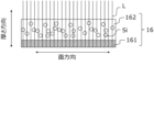
- FIG. FIG. 10 is an image diagram showing a method of determining the distribution of the existence probability of Si element in the thickness direction of the negative electrode mixture layer in the surface direction of the negative electrode mixture layer.
- any of the illustrated lower limits and any of the illustrated upper limits can be arbitrarily combined as long as the lower limit is not greater than or equal to the upper limit.
- a plurality of materials are exemplified, one of them may be selected and used alone, or two or more may be used in combination.
- the present disclosure encompasses a combination of matters described in two or more claims arbitrarily selected from the multiple claims described in the attached claims. In other words, as long as there is no technical contradiction, the matters described in two or more claims arbitrarily selected from the multiple claims described in the attached claims can be combined.
- a negative electrode for a secondary battery includes a negative electrode current collector and a negative electrode mixture layer containing a negative electrode active material.
- the negative electrode current collector is composed of a sheet-like conductive material.
- the negative electrode mixture layer is carried on one or both surfaces of the negative electrode current collector.
- the negative electrode mixture layer is usually a layer (including a membrane or film) made of a negative electrode mixture.
- the negative electrode mixture contains a negative electrode active material as an essential component.
- the negative electrode active material may be any material that reversibly develops capacity by intercalating and deintercalating lithium ions.
- the negative electrode active material contains carbon particles and Si-containing particles.
- the negative electrode active material may contain materials other than the carbon particles and the Si-containing particles, but the main component is the sum of the carbon particles and the Si-containing particles.
- 50 mass % or more or 60 mass % or more (for example, 70 mass % or more or 80 mass % or more) of the negative electrode active material may be carbon particles and Si-containing particles.
- the carbon particles may be crystalline or amorphous, and may each have crystalline and amorphous regions.
- the carbon particles may have electrical conductivity.
- Carbon particles A having crystallinity include graphite, a composite of graphite and amorphous carbon, and the like.
- Graphite may be natural graphite or artificial graphite.
- Amorphous carbon may be hard carbon, soft carbon, or otherwise.
- Graphite refers to carbon particles having an average interplanar spacing d002 of (002) planes of 0.340 nm or less as measured by an X-ray diffraction method.
- XRD X-ray diffraction
- XRD X-ray diffraction
- Si-containing particles are particles containing silicon (Si), and usually part of the Si-containing particles are composed of a silicon phase that expresses electrochemical capacity.
- the Si-containing particles may be Si alone, Si alloys, Si compounds, or the like, but may also be a composite material containing a lithium ion conductive phase and a silicon phase (e.g., silicon particles) dispersed in the lithium ion conductive phase. In composites, the silicon phase should be as fine as possible.
- the composite material is suitable for giving the negative electrode a high capacity while suppressing direct contact between the silicon phase and the electrolytic solution or non-aqueous electrolyte.
- Rmax ⁇ Rmin the difference between the upper limit value Rmax and the lower limit value Rmin in the 1 ⁇ interval: Rmax ⁇ Rmin is 20%. It is below.
- Rmax ⁇ Rmin is 20% or less, further 18% or less or 17%. % can be controlled.
- the distribution of the existence probability R in the surface direction of the negative electrode mixture layer may be measured at one or more cross sections obtained by cutting the negative electrode mixture layer together with the negative electrode current collector along the thickness direction of the negative electrode. Specifically, the distribution of the existence probability R can be obtained by the following method.
- a negative electrode to be measured is prepared.
- the negative electrode mixture layer and the negative electrode current collector are simultaneously cut along the thickness direction of the negative electrode to form a cross section.
- the negative electrode mixture layer may be filled with a thermosetting resin and cured.
- the cross section of the negative electrode is obtained by a CP (cross section polisher) method, an FIB (focused ion beam) method, or the like.
- a cross-sectional sample is observed by SEM. Observation by SEM is performed at a low magnification (for example, 200 times to 1000 times). The SEM image is taken so that a region with a length of 300 ⁇ m or more (preferably 400 ⁇ m or more) in the surface direction of the negative electrode mixture layer is observed.
- the negative electrode to be measured is taken out from a secondary battery with a depth of discharge (DOD) of 90% or more.
- the depth of discharge (DOD) is the ratio of the amount of electricity discharged to the rated amount of electricity that a fully charged battery has.
- the voltage of the fully charged battery corresponds to the end-of-charge voltage.
- the voltage of a fully discharged battery corresponds to the end-of-discharge voltage.
- Elemental analysis by energy dispersive X-ray spectroscopy Elemental analysis by EDX is performed using a cross-sectional SEM image of the negative electrode.
- Si element map is obtained by extracting components derived from the Si element from the EDX analysis data of the cross section of the negative electrode. Thereby, all the components derived from the Si element in the negative electrode mixture layer can be counted.
- the obtained Si element map is expressed as a two-dimensional image defined by the thickness direction and arbitrary surface direction of the negative electrode mixture.
- each straight line represents Si element (a component derived from Si element).
- the existence probability R is measured at a predetermined pitch along the plane direction on the Si element map
- the distribution of the existence probability R in the plane direction is obtained.
- the length of the SEM image in the surface direction of the negative electrode mixture layer is 300 ⁇ m and the predetermined pitch is 5 ⁇ m
- a distribution of R can be drawn.
- FIG. 2 conceptually shows an example of a cross section of the negative electrode 16 when the negative electrode current collector 161 and the negative electrode mixture layer 162 are cut at the same time.
- the Si element map is expressed as a two-dimensional image with the thickness direction of the negative electrode mixture layer 162 as the vertical axis and the arbitrary plane direction as the horizontal axis.
- the plurality of straight lines L are straight lines parallel to the thickness direction of the negative electrode mixture layer 162, and are drawn at a predetermined pitch along the surface direction.
- the 1 ⁇ interval is the interval from ⁇ to ⁇ + ⁇ of the distribution function with the existence probability R on the horizontal axis and the frequency on the vertical axis, where ⁇ is the average of the existence probability R. ⁇ is the standard deviation of the distribution function.
- the affinity between the carbon particles A and the Si-containing particles B can be evaluated using, for example, the amount of DBP (dibutyl phthalate) supplied as an index.
- DBP dibutyl phthalate
- the ratio of the DBP oil amount (DBPB) of the Si-containing particles to the DBP oil amount (DBPA) of the carbon particles: DBPB/DBPA may be 1.0 or less.
- the DBPB/DBPA ratio may be 0.9 or more and 1.0 or less, or may be 0.95 or more and less than 1.0 (eg, 0.99 or less).
- the DBP oil supply amount can be measured using a measuring device (for example, S-500 manufactured by Asahi Research Institute Co., Ltd.) that complies with JIS K6217-4 (ISO4656).
- a measuring device for example, S-500 manufactured by Asahi Research Institute Co., Ltd.
- JIS K6217-4 ISO4656
- the content of carbon particles may be 70% by mass or more and 95% by mass or less, and the content of Si-containing particles may be 5% by mass or more and 30% by mass or less.
- the content of the Si-containing particles in the negative electrode active material is, for example, 0.5% by mass or more, may be 1% by mass or more, or may be 2% by mass or more. It's okay.
- the content of Si-containing particles in the negative electrode active material may be, for example, 20% by mass or less, 15% by mass or less, or 10% by mass or less.
- the Si-containing particles may include first particles having a carbon phase and a silicon phase dispersed within the carbon phase.
- the first particles are particles of a composite material of a carbon phase and a silicon phase.
- the carbon phase can consist of, for example, amorphous carbon.
- the carbon phase may be free of crystalline carbon. In this case, no peak attributed to crystalline carbon is observed in the profile measured by the X-ray diffraction method, and a halo pattern attributed to amorphous carbon is observed.
- the first particles since the content of the silicon phase can be changed arbitrarily, it is easy to design a high-capacity negative electrode.
- Amorphous carbon may be, for example, hard carbon, soft carbon, or anything else.
- Amorphous carbon can be obtained, for example, by sintering a carbon source in an inert atmosphere and pulverizing the resulting sintered body.
- the first particles can be obtained, for example, by mixing a carbon source and Si particles, milling the mixture with a stirrer such as a ball mill, and then firing the mixture in an inert atmosphere.
- carbon sources that can be used include petroleum resins such as coal pitch, petroleum pitch and tar, sugars such as carboxymethyl cellulose (CMC), polyvinylpyrrolidone, cellulose, and sucrose, and water-soluble resins.
- CMC carboxymethyl cellulose
- the carbon source and the Si particles may be dispersed in a dispersion medium such as alcohol. After drying the milled mixture, it is heated in an inert gas atmosphere, for example, at 600° C. or higher and 1000° C. or lower to carbonize the carbon source, thereby forming a carbon phase.
- the carbon phase thus formed is amorphous carbon containing no crystalline carbon.
- the silicon phase dispersed within the carbon phase is usually composed of multiple crystallites.
- the crystallite size of the silicon phase is, for example, 500 nm or less, and may be 30 nm or less. Although the lower limit of the crystallite size of the silicon phase is not particularly limited, it is, for example, 5 nm or more.
- the crystallite size is calculated by Scherrer's formula from the half width of the diffraction peak attributed to the Si (111) plane in the X-ray diffraction (XRD) pattern of the silicon phase.
- the content of the silicon phase contained in the first particles is, for example, 35% by mass or more, may be 45% by mass or more, may be 50% by mass or more, or may be 65% by mass or more. Also, the content of the silicon phase contained in the first particles is, for example, 80% by mass or less, may be 75% by mass or less, may be 70% by mass or less, or may be 65% by mass or less. Within the range in which the upper limit and the lower limit are arbitrarily selected from the above, it becomes easy to achieve both high battery capacity and improved cycle characteristics.
- the content of the silicon phase contained in the first particles can be measured by Si-NMR. Desirable measurement conditions for Si-NMR are shown below.
- Measurement device Solid-state nuclear magnetic resonance spectrometer (INOVA-400) manufactured by Varian Probe: Varian 7mm CPMAS-2 MAS: 4.2kHz MAS speed: 4kHz Pulse: DD (45° pulse + signal acquisition time 1H decouple) Repeat time: 1200sec Observation width: 100kHz Observation center: Around -100 ppm Signal capture time: 0.05 sec Cumulative count: 560 Sample amount: 207.6 mg
- the average particle size of the first particles may be, for example, 1 to 20 ⁇ m, preferably 2 to 12 ⁇ m. Within the above particle size range, the stress caused by the volume change of the first particles due to charge/discharge is easily alleviated, and good cycle characteristics are easily obtained.
- the average particle size of the first particles means the particle size (volume average particle size) at which the volume integrated value is 50% in the particle size distribution measured by the laser diffraction scattering method.
- “LA-750" manufactured by HORIBA, Ltd. can be used as the measuring device.
- the average particle size of the first particles may be obtained from a cross-sectional sample of the negative electrode formed to obtain the SEM image. Equivalent circle diameters of cross sections of 10 or more particles B1 are obtained, and the average value thereof is obtained as the average particle diameter.
- the equivalent circle diameter is the diameter of a circle having the same area as the particle observed in the cross section of the negative electrode.
- the Si-containing particles may include second particles having a silicate phase and a silicon phase dispersed within the silicate phase.
- the second particles are particles of a composite of a silicate phase and a silicon phase. In the second particles, since the content of the silicon phase can be changed arbitrarily, it is easy to design a high-capacity negative electrode.
- the silicate phase may contain, for example, at least one selected from the group consisting of Group 1 elements and Group 2 elements of the long period periodic table.
- Group 1 elements of the long period periodic table and Group 2 elements of the long period periodic table include lithium (Li), potassium (K), sodium (Na), magnesium (Mg), and calcium (Ca). , strontium (Sr), barium (Ba), and the like.
- Other elements may include aluminum (Al), boron (B), lanthanum (La), phosphorus (P), zirconium (Zr), titanium (Ti), and the like.
- a silicate phase containing lithium (hereinafter also referred to as a lithium silicate phase) is preferable because of its small irreversible capacity and high initial charge/discharge efficiency. That is, the second particles may include a lithium silicate phase and a silicon phase dispersed within the lithium silicate phase.
- the lithium silicate phase may be an oxide phase containing lithium (Li), silicon (Si), and oxygen (O), and may contain other elements.
- the atomic ratio of O to Si: O/Si in the lithium silicate phase is greater than 2 and less than 4, for example. In this case, it is advantageous in terms of stability and lithium ion conductivity.
- O/Si is greater than 2 and less than 3.
- the atomic ratio of Li to Si in the lithium silicate phase: Li/Si is greater than 0 and less than 4, for example.
- Elements other than Li, Si and O that can be contained in the lithium silicate phase include, for example, iron (Fe), chromium (Cr), nickel (Ni), manganese (Mn), copper (Cu), molybdenum (Mo), Examples include zinc (Zn) and aluminum (Al).
- the silicon phase dispersed within the silicate phase is usually composed of multiple crystallites.
- the crystallite size of the silicon phase is, for example, 500 nm or less, and may be 30 nm or less. Although the lower limit of the crystallite size of the silicon phase is not particularly limited, it is, for example, 5 nm or more.
- the crystallite size can be measured according to the first particles.
- the content of the silicon phase contained in the second particles is, for example, 40% by mass or more, may be 45% by mass or more, may be 50% by mass or more, or may be 65% by mass or more. Also, the content of the silicon phase contained in the second particles is, for example, 80% by mass or less, may be 75% by mass or less, may be 70% by mass or less, or may be 65% by mass or less. Within the range in which the upper limit and the lower limit are arbitrarily selected from the above, it becomes easy to achieve both high battery capacity and improved cycle characteristics. The content of the silicon phase contained in the second particles can be measured according to the first particles.
- the average particle size of the second particles may be, for example, 1 to 20 ⁇ m, preferably 5 to 12 ⁇ m. Within the above particle size range, the stress caused by the volume change of the second particles due to charge/discharge is easily alleviated, and good cycle characteristics are easily obtained.
- the average particle size of the second particles can be measured according to the first particles.
- the first and second particles are superior in that they have a small irreversible capacity. This is because the carbon phase and the silicate phase have few sites that irreversibly trap lithium ions.
- excellent charge-discharge efficiency can be obtained. In particular, the effect is remarkable at the initial stage of charging and discharging.
- the composition of the first particles and the second particles can be analyzed, for example, by the following method.
- a cross section polisher CP
- FE-SEM field emission scanning electron microscope
- FE-SEM field emission scanning electron microscope
- a backscattered electron image of the cross section of the sample is obtained and the cross section is observed.
- Auger electron spectroscopy (AES) analyzer the observed particles may be subjected to qualitative and quantitative analysis of elements (acceleration voltage 10 kV, beam current 10 nA).
- the carbon particles may contain two or more types of particles with different internal void ratios. In this case, it becomes easy to control the structural strength of the negative electrode mixture layer and the liquid circulation of the electrolytic solution or the non-aqueous electrolyte in the negative electrode mixture layer, and it becomes easy to improve the cycle characteristics.
- the carbon particles may include, for example, third particles having an internal particle porosity of 5% or less and fourth particles having an internal particle porosity of 8% or more and 20% or less.
- the particle internal porosity of the carbon particles may be obtained from a cross-sectional sample of the negative electrode formed to obtain an SEM image.
- the carbon portion and the void portion are distinguished by image processing, and the area of each is determined.
- the ratio of the area of the void portion to the sum of the area of the carbon portion and the area of the void portion is the particle internal porosity.
- the particle internal porosity is an average value obtained from 10 or more predetermined carbon particles.
- the average value of the particle internal porosity of ten or more fourth particles is obtained.
- carbon particles having an internal void ratio of 6.5% or less are classified as third particles, and carbon particles having an internal void ratio exceeding 6.5% are classified as fourth particles.
- the third particles may be crystalline or amorphous, and may each have crystalline and amorphous regions.
- the third particles may be graphite, hard carbon, or soft carbon, for example.
- the average particle size of the third particles may be, for example, 5 to 50 ⁇ m, preferably 12 to 20 ⁇ m.
- the average particle size of the third particles can be measured according to the first particles.
- the fourth particles may be crystalline, amorphous, or have crystalline and amorphous regions.
- the fourth particles may be, for example, graphite, hard carbon, or soft carbon.
- the average particle size of the fourth particles may be, for example, 5 to 50 ⁇ m, preferably 15 to 30 ⁇ m.
- the average particle size of the fourth particles can be measured according to the first particles.
- At least one of the third particles and the fourth particles may contain amorphous carbon, but from the viewpoint of increasing the capacity and improving the cycle characteristics, it is preferable that both the third particles and the fourth particles are graphite. desirable.
- the content of the third particles in the carbon particles is 10% by mass or more and 80% by mass or less, or 10% by mass or more and 50% by mass or less, or 10% by mass. % or more and 30% by mass or less.
- the third particles are arranged in the second region farther from the negative electrode current collector than the first region closer to the negative electrode current collector. It is desirable that it is contained in a large amount in the region.
- the third particles are dense, have high strength, and are suitable for forming sufficient gaps in the surface layer portion of the negative electrode mixture layer where the negative electrode active material is easily crushed. By containing a relatively large amount of the third particles in the second region, it becomes easy to improve the liquid circulation of the electrolytic solution or the non-aqueous electrolyte in the negative electrode mixture layer.
- the fourth particles have a large internal void ratio, they are suitable for forming sufficient gaps in the deep part of the negative electrode mixture layer. Since the first region contains a relatively large amount of the fourth particles, it becomes easy to further improve the liquid circulation of the electrolytic solution or the non-aqueous electrolyte in the negative electrode mixture layer.
- the negative electrode mixture layer is locally affected by charging and discharging of the secondary battery. It is thought that when the expansion is significant, the surface layer is distorted and the strength tends to be deteriorated.
- the difference between the upper limit value Rmax and the lower limit value Rmin of the 1 ⁇ interval of the existence probability R: Rmax ⁇ Rmin is limited to be small, so that the degree of expansion and contraction of the negative electrode due to charging and discharging becomes uniform. Cheap. Therefore, the strength of the surface layer portion is likely to be maintained.
- the mass ratio of the third particles to the total of the third particles and the fourth particles in the second region is, for example, 20% by mass or more and 80% by mass or less, or 30% by mass or more and 60% by mass or less, or 35% by mass. Above, 50 mass % or less may be sufficient.
- the mass ratio of the third particles to the total of the third particles and the fourth particles in the first region is, for example, 0% by mass or more and 40% by mass or less, or 0% by mass or more and 30% by mass or less, or 0% by mass. Above, 20 mass % or less may be sufficient.
- a secondary battery includes a positive electrode, a negative electrode, and a non-aqueous electrolyte.
- the negative electrode is the negative electrode described above.
- a positive electrode and a negative electrode are arranged so as to face each other with a separator interposed therebetween.
- the negative electrode includes a negative electrode mixture layer containing a negative electrode active material and a negative electrode current collector. can be applied to the surface of the negative electrode current collector and dried. The dried coating film may be rolled if necessary.
- the negative electrode mixture contains a negative electrode active material as an essential component, and may contain a binder, a thickener, a conductive agent, etc. as optional components.
- the negative electrode active material contains carbon particles and Si-containing particles, as described above.
- a resin material is used as the binder for the negative electrode.
- binders include fluororesins, polyolefin resins, polyamide resins, polyimide resins, acrylic resins, vinyl resins, and rubber-like materials (eg, styrene-butadiene copolymer (SBR)).
- SBR styrene-butadiene copolymer
- the binder may be used alone or in combination of two or more.
- thickeners examples include cellulose derivatives such as cellulose ethers. Examples of cellulose derivatives include carboxymethyl cellulose (CMC) and modified products thereof, methyl cellulose, and the like. A thickener may be used individually by 1 type, and may be used in combination of 2 or more type.
- CMC carboxymethyl cellulose
- Examples of conductive materials include carbon nanotubes (CNT), carbon fibers other than CNT, and conductive particles (eg, carbon black, graphite).
- CNT carbon nanotubes
- carbon fibers other than CNT carbon fibers other than CNT
- conductive particles eg, carbon black, graphite
- the dispersion medium used for the negative electrode slurry is not particularly limited, but examples include water, alcohol, N-methyl-2-pyrrolidone (NMP), mixed solvents thereof, and the like.
- a metal foil can be used as the negative electrode current collector.
- the negative electrode current collector may be porous.
- materials for the negative electrode current collector include stainless steel, nickel, nickel alloys, copper, and copper alloys.
- the thickness of the negative electrode current collector is not particularly limited, but is, for example, 1 to 50 ⁇ m, and may be 5 to 30 ⁇ m.
- the positive electrode contains a positive electrode active material.
- a positive electrode generally includes a positive electrode current collector and a layered positive electrode mixture (hereinafter referred to as a “positive electrode mixture layer”) held by the positive electrode current collector.
- the positive electrode mixture layer can be formed by coating the surface of the positive electrode current collector with a positive electrode slurry in which the components of the positive electrode mixture are dispersed in a dispersion medium, and drying the slurry. The dried coating film may be rolled if necessary.
- the positive electrode mixture contains a positive electrode active material as an essential component, and may contain a binder, a thickener, and the like as optional components.
- the positive electrode active material may be a material that can be used as a positive electrode active material for non-aqueous secondary batteries (especially lithium ion secondary batteries), but from the viewpoint of increasing capacity, a lithium transition metal composite containing at least nickel as a transition metal Including oxide (composite oxide N).
- the ratio of the composite oxide N in the positive electrode active material is, for example, 70% by mass or more, may be 90% by mass or more, or may be 95% by mass or more.
- the composite oxide N may be, for example, a lithium transition metal composite oxide having a layered rock salt structure and containing Ni and at least one selected from the group consisting of Co, Mn and Al.
- a lithium transition metal composite oxide having a layered rock salt structure and containing Ni and at least one selected from the group consisting of Co, Mn and Al.
- it has a layered rock salt structure, contains Ni and at least one selected from the group consisting of Co, Mn and Al, and the proportion of Ni in the metal elements other than Li is 80 atomic% or more.
- a lithium transition metal composite oxide is also referred to as a “composite oxide HN”.
- the proportion of the composite oxide HN in the composite oxide N used as the positive electrode active material is, for example, 90% by mass or more, may be 95% by mass or more, or may be 100%. The higher the Ni ratio, the more lithium ions can be extracted from the composite oxide HN during charging, and the capacity can be increased.
- Co, Mn and Al contribute to stabilization of the crystal structure of the composite oxide HN with a high Ni content. From the viewpoint of manufacturing cost reduction, it is desirable that the Co content is as small as possible, but from the viewpoint of improving durability, it is desirable to include Co in the composite oxide HN.
- the composite oxide HN with a low Co content (or no Co) may contain Mn and Al.
- the proportion of Co in metal elements other than Li is desirably 10 atomic % or less, more desirably 5 atomic % or less, and does not have to contain Co. From the viewpoint of stabilizing the crystal structure of the composite oxide HN, 1 atomic % or more or 1.5 atomic % or more (for example, 5 atomic % or more) of Co may be included.
- the proportion of Mn in metal elements other than Li may be 10 atomic % or less, or may be 5 atomic % or less.
- the ratio of Mn to the metal elements other than Li may be 1 atomic % or more, 3 atomic % or more, or 5 atomic % or more. When limiting the range, these upper and lower limits can be combined arbitrarily.
- the ratio of Al to the metal elements other than Li may be 10 atomic % or less, or 5 atomic % or less.
- the ratio of Al to the metal elements other than Li may be 1 atomic % or more, 3 atomic % or more, or 5 atomic % or more. When limiting the range, these upper and lower limits can be combined arbitrarily.
- the composite oxide HN is represented, for example, by the formula: Li ⁇ Ni (1-x1-x2-yz) Co x1 Mn x2 Al y M z O 2+ ⁇ .
- Element M is an element other than Li, Ni, Co, Mn, Al and oxygen.
- Mn contributes to stabilization of the crystal structure of the composite oxide HN, and the composite oxide HN contains inexpensive Mn, which is advantageous for cost reduction.
- Al contributes to stabilization of the crystal structure of the composite oxide HN.
- ⁇ indicating the atomic ratio of lithium is, for example, 0.95 ⁇ 1.05. ⁇ increases and decreases due to charging and discharging. In (2+ ⁇ ) representing the atomic ratio of oxygen, ⁇ satisfies ⁇ 0.05 ⁇ 0.05.
- 1-x1-x2-yz ( v), which indicates the atomic ratio of Ni, is, for example, 0.8 or more, may be 0.85 or more, or may be 0.90 or more, or 0.95 or more. Also, v may be 0.98 or less, or 0.95 or less.
- x1 indicating the atomic ratio of Co is, for example, 0.1 or less (0 ⁇ x1 ⁇ 0.1)
- x2 indicating the atomic ratio of Mn is, for example, 0.1 or less (0 ⁇ x2 ⁇ 0.1 )
- y indicating the atomic ratio of Al is, for example, 0.1 or less (0 ⁇ y ⁇ 0.1)
- z indicating the atomic ratio of the element M is, for example, 0 ⁇ z ⁇ 0.10 is.
- the element M may be at least one selected from the group consisting of Ti, Zr, Nb, Mo, W, Fe, Zn, B, Si, Mg, Ca, Sr, Sc and Y. Among them, when at least one selected from the group consisting of Nb, Sr and Ca is contained in the composite oxide HN, the surface structure of the composite oxide HN is stabilized, the resistance is reduced, and the metal is further eluted. considered to be suppressed. It is more effective when the element M is unevenly distributed near the particle surface of the composite oxide HN.
- a resin material is used as the binder for the positive electrode.
- binders include fluorine resins, polyolefin resins, polyamide resins, polyimide resins, acrylic resins, and vinyl resins.
- the binder may be used alone or in combination of two or more.
- Examples of conductive materials include carbon nanotubes (CNT), carbon fibers other than CNT, and conductive particles (eg, carbon black, graphite).
- CNT carbon nanotubes
- carbon fibers other than CNT carbon fibers other than CNT
- conductive particles eg, carbon black, graphite
- the dispersion medium used for the positive electrode slurry is not particularly limited, but examples include water, alcohol, N-methyl-2-pyrrolidone (NMP), mixed solvents thereof, and the like.
- a metal foil can be used as the positive electrode current collector.
- the positive electrode current collector may be porous. Examples of porous current collectors include nets, punched sheets, expanded metals, and the like. Examples of materials for the positive electrode current collector include stainless steel, aluminum, aluminum alloys, and titanium.
- the thickness of the positive electrode current collector is not particularly limited, but is, for example, 1 to 50 ⁇ m, and may be 5 to 30 ⁇ m.
- the electrolyte contains a solvent and a solute dissolved in the solvent.
- a solute is an electrolyte salt that ionically dissociates in the electrolyte.
- Solutes can include, for example, lithium salts.
- Components of electrolytes other than solvents and solutes are additives.
- the electrolyte may contain various additives.
- aqueous solvent or a non-aqueous solvent is used as the solvent.
- non-aqueous solvents include cyclic carbonates, chain carbonates, cyclic carboxylates, chain carboxylates, and the like.
- Cyclic carbonates include propylene carbonate (PC), ethylene carbonate (EC), vinylene carbonate (VC) and the like.
- Chain carbonates include diethyl carbonate (DEC), ethyl methyl carbonate (EMC), dimethyl carbonate (DMC) and the like.
- cyclic carboxylic acid esters include ⁇ -butyrolactone (GBL) and ⁇ -valerolactone (GVL).
- Chain carboxylic acid esters include methyl acetate, ethyl acetate, propyl acetate, methyl propionate (MP), ethyl propionate (EP) and the like.
- the non-aqueous solvent may be used singly or in combination of two or more.
- lithium salts include lithium salts of chlorine - containing acids (LiClO4, LiAlCl4 , LiB10Cl10 , etc.), lithium salts of fluorine - containing acids ( LiPF6 , LiPF2O2 , LiBF4 , LiSbF6 , LiAsF6 , LiCF3SO3 , LiCF3CO2 , etc.), lithium salts of fluorine-containing acid imides (LiN( FSO2 ) 2 , LiN ( CF3SO2 ) 2 , LiN ( CF3SO2 ) ( C4F9SO 2 ), LiN ( C2F5SO2 ) 2 , etc.), lithium halides ( LiCl, LiBr, LiI, etc.) can be used. Lithium salts may be used singly or in combination of two or more.
- the concentration of the lithium salt in the electrolytic solution may be 1 mol/liter or more and 2 mol/liter or less, or may be 1 mol/liter or more and 1.5 mol/liter or less.
- the lithium salt concentration is not limited to the above.
- Separator It is desirable to interpose a separator between the positive electrode and the negative electrode.
- the separator has high ion permeability and moderate mechanical strength and insulation.
- a microporous thin film, a woven fabric, a nonwoven fabric, or the like can be used as the separator.
- Polyolefins such as polypropylene and polyethylene are preferable as the material of the separator.
- An example of the structure of a non-aqueous secondary battery is a structure in which an electrode group, in which a positive electrode and a negative electrode are wound with a separator interposed therebetween, is housed in an outer package together with an electrolytic solution.
- an electrode group in which a positive electrode and a negative electrode are wound with a separator interposed therebetween
- an electrolytic solution e.g., aqueous solution
- a laminated electrode group in which a positive electrode and a negative electrode are laminated with a separator interposed therebetween may be used.
- the form of the secondary battery is also not limited, and may be, for example, cylindrical, square, coin, button, laminate, or the like.
- FIG. 1 is a vertical cross-sectional view of a cylindrical non-aqueous secondary battery 10 that is an example of the present embodiment.
- the present disclosure is not limited to the following configurations.
- the secondary battery 10 includes an electrode group 18, an electrolytic solution (not shown), and a bottomed cylindrical battery can 22 that accommodates them.
- a sealing member 11 is crimped and fixed to the opening of the battery can 22 via a gasket 21 . The inside of the battery is thereby sealed.
- the sealing body 11 includes a valve body 12 , a metal plate 13 , and an annular insulating member 14 interposed between the valve body 12 and the metal plate 13 .
- the valve body 12 and the metal plate 13 are connected to each other at their respective centers.
- a positive electrode lead 15 a led out from the positive electrode plate 15 is connected to the metal plate 13 . Therefore, the valve body 12 functions as a positive external terminal.
- a negative lead 16 a led out from the negative plate 16 is connected to the inner surface of the bottom of the battery can 22 .
- An annular groove 22 a is formed near the open end of the battery can 22 .
- a first insulating plate 23 is arranged between one end surface of the electrode group 18 and the annular groove portion 22a.
- a second insulating plate 24 is arranged between the other end surface of the electrode group 18 and the bottom of the battery can 22 .
- the electrode group 18 is formed by winding the positive electrode plate 15 and the negative electrode plate 16 with the separator 17 interposed therebetween.
- a non-aqueous secondary battery was produced and evaluated by the following procedure.
- (1) Fabrication of positive electrode LiNi 0.91 Co 0.04 Al 0.05 O 2 was used as a positive electrode active material. 100 parts by mass of a positive electrode active material (average particle size: 12 ⁇ m), 1 part by mass of carbon nanotubes, 1 part by mass of polyvinylidene fluoride, and an appropriate amount of NMP were mixed to obtain a positive electrode slurry. Next, the positive electrode slurry was applied to both surfaces of the aluminum foil, the coating film was dried, and then rolled to form positive electrode mixture layers on both surfaces of the aluminum foil, thereby obtaining a positive electrode.
- Negative Electrode 90 parts by mass of first carbon particles A, 10 parts by mass of Si-containing particles B, 1 part by mass of sodium salt of CMC (CMC-Na), and 1 part by mass of SBR. It was mixed with water to prepare a first negative electrode slurry.
- the first carbon particles A consist of 40% by mass of third particles A1 (average particle size 15 ⁇ m) having an internal particle porosity of 2.4%, and 40% by mass of fourth particles A2 (average particle size diameter 18 ⁇ m) is included in 60% by mass.
- a second negative electrode slurry was prepared. All (100% by mass) of the second carbon particles A are the fourth particles A2 (average particle size 18 ⁇ m) having an internal void ratio of 12.8%.
- the silicon-containing particles B are first particles B1 having a carbon phase and a silicon phase dispersed in the carbon phase. prepared.
- the first particles B1 were prepared by mixing carbon source pitch and Si coarse particles, milling the mixture with a ball mill, and then firing the mixture in an inert atmosphere.
- the crystallite size of the silicon phase (silicon particles) dispersed in the carbon phase was found to be 200 nm or less by the method described above. According to XRD analysis, the carbon phase was amorphous carbon containing no crystalline carbon.
- the DBP oil amount (DBPB) of the Si-containing particles B (first particles B1) with respect to the DBP oil amount (DBPA) of the first carbon particles A (third particles A1:fourth particles A2 (mass ratio) 40:60)
- the ratio: DBPB/DBPA was 0.93.
- the second negative electrode slurry was applied to both sides of the copper foil, which was the negative electrode current collector, and the coating was dried. Thereafter, the first negative electrode slurry was applied onto the coating film of the second negative electrode slurry, dried, and rolled to form negative electrode mixture layers on both sides of the copper foil, thereby obtaining a negative electrode.
- the thickness of the negative electrode mixture layer was 81 ⁇ m on one side, and the coating thicknesses of the first negative electrode slurry and the second negative electrode slurry were the same.
- the distribution of the presence probability R of the Si element in the thickness direction of the negative electrode mixture layer of the obtained negative electrode in the surface direction of the negative electrode mixture layer is obtained, and the difference between the upper limit value Rmax and the lower limit value Rmin in the 1 ⁇ interval: Rmax ⁇ Rmin was found to be 18%.
- the pitch of straight lines parallel to the thickness direction of the plurality of negative electrode mixture layers drawn on the Si element map was set to 5 ⁇ m.
- the concentration of LiPF 6 in the electrolyte was set to 1.3 mol/L.
- Example 2>> By changing the Si-containing particles B (first particles B1), the DBP oil supply amount of the Si-containing particles B (first particles B1) and the upper limit value Rmax and the lower limit value Rmin of the 1 ⁇ section of the distribution of the existence probability R are changed.
- a battery X2 was produced in the same manner as in Example 1, except that the
- Second particles B2 comprising a lithium silicate phase ( Li2Si2O5 ) and a silicon phase dispersed in the lithium silicate phase were used instead of the Si-containing particles B (first particles B1).
- a battery Y1 was produced in the same manner as in Example 1 except for the above.
- a secondary battery having a negative electrode according to the present disclosure is suitable for main power sources such as mobile communication devices and portable electronic devices, and vehicle power sources, but the applications are not limited to these.
Abstract
Description
まず、測定対象の負極を準備する。次に、負極合材層と負極集電体とを同時に負極の厚さ方向に沿って切断して断面を形成する。その際、負極合材層に熱硬化性樹脂を充填して硬化させてもよい。例えば、CP(クロスセクションポリッシャー)法、FIB(集束イオンビーム)法等により負極の上記断面を得る。断面試料をSEMで観察する。SEMによる観察は、低倍率(例えば、200倍~1000倍)で行う。SEM像は、負極合材層の面方向における長さ300μm以上(望ましくは400μm以上)の領域が観測されるように撮影する。 (1) Imaging of Cross Section of Negative Electrode with Scanning Electron Microscope (SEM) First, a negative electrode to be measured is prepared. Next, the negative electrode mixture layer and the negative electrode current collector are simultaneously cut along the thickness direction of the negative electrode to form a cross section. At that time, the negative electrode mixture layer may be filled with a thermosetting resin and cured. For example, the cross section of the negative electrode is obtained by a CP (cross section polisher) method, an FIB (focused ion beam) method, or the like. A cross-sectional sample is observed by SEM. Observation by SEM is performed at a low magnification (for example, 200 times to 1000 times). The SEM image is taken so that a region with a length of 300 μm or more (preferably 400 μm or more) in the surface direction of the negative electrode mixture layer is observed.
負極の断面のSEM像を用いてEDXによる元素分析を行う。 (2) Elemental analysis by energy dispersive X-ray spectroscopy (EDX) Elemental analysis by EDX is performed using a cross-sectional SEM image of the negative electrode.
負極の断面のEDX分析データからSi元素に由来する成分を抽出することで、Si元素マップを得る。これにより負極合材層の全てのSi元素に由来する成分をカウントすることができる。 (3) Creation of Silicon Phase Map A Si element map is obtained by extracting components derived from the Si element from the EDX analysis data of the cross section of the negative electrode. Thereby, all the components derived from the Si element in the negative electrode mixture layer can be counted.
得られたSi元素マップは、負極合材の厚さ方向と任意の面方向とで定義される二次元画像として表現される。そのようなSi元素マップにおいて、負極合材層の厚さ方向と平行な直線を、上記面方向に沿って、例えば5μmピッチで複数描くとき、各直線はSi元素(Si元素に由来する成分)と交差する部分を有し得る。各直線のSi元素と交差する部分の合計長さLBの負極合材層の厚さTに対する比率R(=LB/T)は、負極合材層の面方向における任意の点におけるSi元素の存在確率Rを示す。 (4) Measurement of Distribution of Existence Probability R The obtained Si element map is expressed as a two-dimensional image defined by the thickness direction and arbitrary surface direction of the negative electrode mixture. In such a Si element map, when a plurality of straight lines parallel to the thickness direction of the negative electrode mixture layer are drawn along the surface direction, for example, at a pitch of 5 μm, each straight line represents Si element (a component derived from Si element). can have a portion that intersects with The ratio R (= LB/T) of the total length LB of the portion of each straight line intersecting with the Si element to the thickness T of the negative electrode mixture layer (= LB/T) is the presence of Si element at an arbitrary point in the plane direction of the negative electrode mixture layer. Denote the probability R.
プローブ:Varian 7mm CPMAS-2
MAS:4.2kHz
MAS速度:4kHz
パルス:DD(45°パルス+シグナル取込時間1Hデカップル)
繰り返し時間:1200sec
観測幅:100kHz
観測中心:-100ppm付近
シグナル取込時間:0.05sec
積算回数:560
試料量:207.6mg Measurement device: Solid-state nuclear magnetic resonance spectrometer (INOVA-400) manufactured by Varian
Probe: Varian 7mm CPMAS-2
MAS: 4.2kHz
MAS speed: 4kHz
Pulse: DD (45° pulse + signal acquisition time 1H decouple)
Repeat time: 1200sec
Observation width: 100kHz
Observation center: Around -100 ppm Signal capture time: 0.05 sec
Cumulative count: 560
Sample amount: 207.6 mg
負極は、既述のように、負極活物質を含む負極合材層と、負極集電体とを具備し、負極合材層は、負極合材の構成成分を分散媒に分散させた負極スラリを、負極集電体の表面に塗布し、乾燥させることにより形成できる。乾燥後の塗膜を、必要により圧延してもよい。 [Negative electrode]
As described above, the negative electrode includes a negative electrode mixture layer containing a negative electrode active material and a negative electrode current collector. can be applied to the surface of the negative electrode current collector and dried. The dried coating film may be rolled if necessary.
負極活物質は、既述のように、炭素粒子と、Si含有粒子とを含む。 (Negative electrode active material)
The negative electrode active material contains carbon particles and Si-containing particles, as described above.
正極は、正極活物質を含む。正極は、通常、正極集電体と、正極集電体に保持された層状の正極合材(以下「正極合材層」と称する。)を備えている。正極合材層は、正極合材の構成成分を分散媒に分散させた正極スラリを、正極集電体の表面に塗布し、乾燥させることにより形成できる。乾燥後の塗膜を必要により圧延してもよい。正極合材は、必須成分として、正極活物質を含み、任意成分として、結着剤、増粘剤等を含み得る。 [Positive electrode]
The positive electrode contains a positive electrode active material. A positive electrode generally includes a positive electrode current collector and a layered positive electrode mixture (hereinafter referred to as a “positive electrode mixture layer”) held by the positive electrode current collector. The positive electrode mixture layer can be formed by coating the surface of the positive electrode current collector with a positive electrode slurry in which the components of the positive electrode mixture are dispersed in a dispersion medium, and drying the slurry. The dried coating film may be rolled if necessary. The positive electrode mixture contains a positive electrode active material as an essential component, and may contain a binder, a thickener, and the like as optional components.
正極活物質は、非水系二次電池(特にリチウムイオン二次電池)の正極活物質として用い得る材料であればよいが、高容量化の観点から、少なくとも遷移金属としてニッケルを含むリチウム遷移金属複合酸化物(複合酸化物N)を含む。正極活物質に占める複合酸化物Nの割合は、例えば、70質量%以上であり、90質量%以上でもよく、95質量%以上でもよい。 (Positive electrode active material)
The positive electrode active material may be a material that can be used as a positive electrode active material for non-aqueous secondary batteries (especially lithium ion secondary batteries), but from the viewpoint of increasing capacity, a lithium transition metal composite containing at least nickel as a transition metal Including oxide (composite oxide N). The ratio of the composite oxide N in the positive electrode active material is, for example, 70% by mass or more, may be 90% by mass or more, or may be 95% by mass or more.
電解液は、溶媒と、溶媒に溶解した溶質とを含む。溶質は、電解液中でイオン解離する電解質塩である。溶質は、例えば、リチウム塩を含み得る。溶媒および溶質以外の電解液の成分は添加剤である。電解液には、様々な添加剤が含まれ得る。 [Electrolyte]
The electrolyte contains a solvent and a solute dissolved in the solvent. A solute is an electrolyte salt that ionically dissociates in the electrolyte. Solutes can include, for example, lithium salts. Components of electrolytes other than solvents and solutes are additives. The electrolyte may contain various additives.
正極と負極との間には、セパレータを介在させることが望ましい。セパレータは、イオン透過度が高く、適度な機械的強度および絶縁性を備えている。セパレータとしては、微多孔薄膜、織布、不織布等を用いることができる。セパレータの材質としては、ポリプロピレン、ポリエチレン等のポリオレフィンが好ましい。 [Separator]
It is desirable to interpose a separator between the positive electrode and the negative electrode. The separator has high ion permeability and moderate mechanical strength and insulation. A microporous thin film, a woven fabric, a nonwoven fabric, or the like can be used as the separator. Polyolefins such as polypropylene and polyethylene are preferable as the material of the separator.
下記の手順で、非水系二次電池を作製し、評価を行った。
(1)正極の作製
正極活物質としてLiNi0.91Co0.04Al0.05O2を用いた。正極活物質(平均粒径12μm)を100質量部と、カーボンナノチューブ1質量部と、ポリフッ化ビニリデン1質量部と、適量のNMPとを混合し、正極スラリを得た。次に、アルミニウム箔の両面に正極スラリを塗布し、塗膜を乾燥させた後、圧延して、アルミニウム箔の両面に正極合材層を形成し、正極を得た。 <<Example 1>>
A non-aqueous secondary battery was produced and evaluated by the following procedure.
(1) Fabrication of positive electrode LiNi 0.91 Co 0.04 Al 0.05 O 2 was used as a positive electrode active material. 100 parts by mass of a positive electrode active material (average particle size: 12 μm), 1 part by mass of carbon nanotubes, 1 part by mass of polyvinylidene fluoride, and an appropriate amount of NMP were mixed to obtain a positive electrode slurry. Next, the positive electrode slurry was applied to both surfaces of the aluminum foil, the coating film was dried, and then rolled to form positive electrode mixture layers on both surfaces of the aluminum foil, thereby obtaining a positive electrode.
第1炭素粒子Aを90質量部と、Si含有粒子Bを10質量部と、CMCのナトリウム塩(CMC-Na)1質量部と、SBRを1質量部と、適量の水とを混合し、第1負極スラリを調製した。第1炭素粒子Aは、粒子内部空隙率が2.4%の第三粒子A1(平均粒径15μm)を40質量%と、粒子内部空隙率が12.8%の第四粒子A2(平均粒径18μm)を60質量%含む。 (2) Preparation of Negative Electrode 90 parts by mass of first carbon particles A, 10 parts by mass of Si-containing particles B, 1 part by mass of sodium salt of CMC (CMC-Na), and 1 part by mass of SBR. It was mixed with water to prepare a first negative electrode slurry. The first carbon particles A consist of 40% by mass of third particles A1 (
FEC、EC、EMCおよびDMCの混合溶媒(FEC:EC:EMC:DMC=10:5:5:80(体積比))に、LiPF6を溶解させて電解液を調製した。電解液におけるLiPF6の濃度は1.3mol/Lとした。 (3) Preparation of Electrolyte Solution An electrolyte solution was prepared by dissolving LiPF 6 in a mixed solvent of FEC, EC, EMC and DMC (FEC:EC:EMC:DMC=10:5:5:80 (volume ratio)). bottom. The concentration of LiPF 6 in the electrolyte was set to 1.3 mol/L.
正極にアルミニウム製の正極リードの一端部を取り付けた。負極にニッケル製の負極リードの一端部を取り付けた。ポリエチレン製のセパレータを介して正極および負極を巻回して電極体を作製した。電極体を105℃で2時間真空乾燥した後、負極端子を兼ねる有底円筒形状の電池ケースに収容した。電池ケースには、鉄製ケースを用いた。次いで、電池ケース内に電解液を注入した後、正極端子を兼ねる金属製の封口体を用いて電池ケースの開口部を閉じた。このとき、封口体と電池ケースの開口端部との間に樹脂製のガスケットを介在させた。このようにして、21700型の円筒形リチウムイオン二次電池(電池X1)を作製した。
なお、表1において、X1~X3は実施例1~3の電池、Y1~Y2は比較例1~2の電池である。 (4) Preparation of Lithium Ion Secondary Battery One end of a positive electrode lead made of aluminum was attached to the positive electrode. One end of a negative electrode lead made of nickel was attached to the negative electrode. An electrode body was produced by winding the positive electrode and the negative electrode through a separator made of polyethylene. After vacuum drying the electrode assembly at 105° C. for 2 hours, it was housed in a bottomed cylindrical battery case that also serves as a negative electrode terminal. An iron case was used as the battery case. Next, after the electrolytic solution was injected into the battery case, the opening of the battery case was closed using a metal sealing member that also served as a positive electrode terminal. At this time, a resin gasket was interposed between the sealing member and the open end of the battery case. Thus, a 21700 type cylindrical lithium ion secondary battery (battery X1) was produced.
In Table 1, X1-X3 are the batteries of Examples 1-3, and Y1-Y2 are the batteries of Comparative Examples 1-2.
<充放電サイクル>
完成させた電池の充放電サイクルを下記条件で50サイクル行った。初回の放電容量C0を100%としたときの、50サイクル後の放電容量C50の劣化率(C0とC50との差)を求めた。 (5) Evaluation <charge-discharge cycle>
The completed battery was subjected to 50 charge/discharge cycles under the following conditions. The deterioration rate (difference between C0 and C50) of the discharge capacity C50 after 50 cycles was determined when the initial discharge capacity C0 was taken as 100%.
25℃の環境下で、0.2Itの定電流で電圧が4.2Vになるまで充電し、その後、4.2Vの定電圧で電流が0.02Itになるまで充電した。定電圧充電後の電池を20分間休止させた。 <charging>
In an environment of 25° C., the battery was charged at a constant current of 0.2 It until the voltage reached 4.2 V, and then charged at a constant voltage of 4.2 V until the current reached 0.02 It. After the constant voltage charging, the battery was rested for 20 minutes.
休止後、25℃の環境下で、0.2Itの定電流で電圧が2.5Vに達するまで放電した。 <Discharge>
After resting, the battery was discharged at a constant current of 0.2 It in an environment of 25° C. until the voltage reached 2.5 V.
Si含有粒子B(第一粒子B1)を変更することにより、Si含有粒子B(第一粒子B1)のDBP給油量と、存在確率Rの分布の1σ区間の上限値Rmaxと下限値Rminを変化させたこと以外、実施例1と同様に電池X2を作製した。 <<Example 2>>
By changing the Si-containing particles B (first particles B1), the DBP oil supply amount of the Si-containing particles B (first particles B1) and the upper limit value Rmax and the lower limit value Rmin of the 1σ section of the distribution of the existence probability R are changed. A battery X2 was produced in the same manner as in Example 1, except that the
負極スラリ調製時の合材混合時間を変更することにより、存在確率Rの分布の1σ区間の上限値Rmaxと下限値Rminを変化させたこと以外、実施例2と同様に電池X3を作製した。 <<Example 3>>
A battery X3 was produced in the same manner as in Example 2, except that the upper limit value Rmax and the lower limit value Rmin of the 1σ interval of the distribution of the existence probability R were changed by changing the mixture mixing time during preparation of the negative electrode slurry.
Si含有粒子B(第一粒子B1)の代わりに、リチウムシリケート相(Li2Si2O5)と、リチウムシリケート相内に分散しているシリコン相とを備える第二粒子B2を用いた。上記以外、実施例1と同様に電池Y1を作製した。 <<Comparative example 1>>
Second particles B2 comprising a lithium silicate phase ( Li2Si2O5 ) and a silicon phase dispersed in the lithium silicate phase were used instead of the Si-containing particles B (first particles B1). A battery Y1 was produced in the same manner as in Example 1 except for the above.
Si含有粒子B(第一粒子B1)を変更することにより、Si含有粒子B(第一粒子B1)のDBP給油量と、存在確率Rの分布の1σ区間の上限値Rmaxと下限値Rminとを変化させたこと以外、実施例1と同様に電池Y2を作製した。 <<Comparative Example 2>>
By changing the Si-containing particles B (first particles B1), the DBP oil supply amount of the Si-containing particles B (first particles B1) and the upper limit value Rmax and the lower limit value Rmin of the 1σ section of the distribution of the existence probability R are changed. A battery Y2 was produced in the same manner as in Example 1, except that the conditions were changed.

第1負極スラリおよび第2負極スラリにおいて、負極活物質におけるSi含有粒子B(第一粒子B1)の含有率を12質量%に変更することにより、存在確率Rの分布の1σ区間の上限値Rmaxと下限値Rminとを変化させたこと以外、実施例2と同様に電池X4を作製した。 <<Example 4>>
In the first negative electrode slurry and the second negative electrode slurry, by changing the content of the Si-containing particles B (first particles B1) in the negative electrode active material to 12% by mass, the upper limit value Rmax of the 1σ interval of the distribution of the existence probability R A battery X4 was produced in the same manner as in Example 2, except that the lower limit value Rmin was changed.
第1負極スラリおよび第2負極スラリにおいて、負極活物質におけるSi含有粒子B(第一粒子B1)の含有率を12質量%に変更するとともに、Si含有粒子B(第一粒子B1)を変更することにより、Si含有粒子B(第一粒子B1)のDBP給油量と、存在確率Rの分布の1σ区間の上限値Rmaxと下限値Rminとを変化させたこと以外、実施例1と同様に電池Y3を作製した。 <<Comparative Example 3>>
In the first negative electrode slurry and the second negative electrode slurry, the content of the Si-containing particles B (first particles B1) in the negative electrode active material is changed to 12% by mass, and the Si-containing particles B (first particles B1) are changed. Thus, the battery was produced in the same manner as in Example 1 except that the DBP oil supply amount of the Si-containing particles B (first particles B1) and the upper limit value Rmax and the lower limit value Rmin of the 1σ interval of the distribution of the existence probability R were changed. Y3 was made.

Claims (9)
- 負極集電体と、負極活物質を含む負極合材層と、を備え、
前記負極活物質は、炭素粒子と、Si含有粒子と、を含み、
前記負極合材層の厚さ方向におけるSi元素の存在確率の前記負極合材層の面方向における分布において、1σ区間の上限値Rmaxと下限値Rminとの差:Rmax-Rminが20%以下である、二次電池用負極。 A negative electrode current collector and a negative electrode mixture layer containing a negative electrode active material,
The negative electrode active material includes carbon particles and Si-containing particles,
In the distribution of the presence probability of Si element in the thickness direction of the negative electrode mixture layer in the plane direction of the negative electrode mixture layer, the difference between the upper limit value Rmax and the lower limit value Rmin in the 1σ interval: Rmax−Rmin is 20% or less A negative electrode for secondary batteries. - 前記Si含有粒子は、第一粒子を含み、
前記第一粒子は、炭素相と、前記炭素相内に分散しているシリコン相と、を有する、請求項1に記載の二次電池用負極。 The Si-containing particles include first particles,
2. The negative electrode for a secondary battery according to claim 1, wherein said first particles have a carbon phase and a silicon phase dispersed in said carbon phase. - 前記炭素相は、結晶質炭素を含まない、請求項2に記載の二次電池用負極。 The negative electrode for a secondary battery according to claim 2, wherein the carbon phase does not contain crystalline carbon.
- 前記炭素粒子のDBP給油量(DBPA)に対する前記Si含有粒子のDBP給油量(DBPB)の比:DBPB/DBPAが、0.9以上、1.0以下である、請求項2または3に記載の二次電池用負極。 4. The ratio of the DBP oil amount (DBPB) of the Si-containing particles to the DBP oil amount (DBPA) of the carbon particles: DBPB/DBPA according to claim 2 or 3, which is 0.9 or more and 1.0 or less. Negative electrode for secondary batteries.
- 前記負極活物質において、
前記炭素粒子の含有率は、70質量%以上、95質量%以下であり、
前記Si含有粒子の含有率は、5質量%以上、30質量%以下である、請求項1~4のいずれか1項に記載の二次電池用負極。 In the negative electrode active material,
The content of the carbon particles is 70% by mass or more and 95% by mass or less,
5. The negative electrode for a secondary battery according to claim 1, wherein the content of said Si-containing particles is 5% by mass or more and 30% by mass or less. - 前記Si含有粒子は、第二粒子を含み、
前記第二粒子は、シリケート相と、前記シリケート相内に分散しているシリコン相とを有する、請求項1~5のいずれか1項に記載の二次電池用負極。 The Si-containing particles include second particles,
6. The negative electrode for a secondary battery according to claim 1, wherein said second particles have a silicate phase and a silicon phase dispersed in said silicate phase. - 前記炭素粒子が、第三粒子および第四粒子を含み、
前記第三粒子の粒子内部空隙率が、5%以下であり、
前記第四粒子の粒子内部空隙率が、8%以上、20%以下であり、
前記炭素粒子において、前記第三粒子の含有率は、10質量%以上、80質量%以下である、請求項1~6のいずれか1項に記載の二次電池用負極。 the carbon particles include third particles and fourth particles,
The third particles have a particle internal porosity of 5% or less,
The fourth particles have a particle internal porosity of 8% or more and 20% or less,
7. The negative electrode for a secondary battery according to claim 1, wherein the content of said third particles in said carbon particles is 10% by mass or more and 80% by mass or less. - 前記負極合材層を厚さ方向において同じ厚さの第1領域と第2領域とに分けるとき、
前記第三粒子が、前記負極集電体に近い前記第1領域よりも、前記負極集電体から遠い前記第2領域に多い量で含まれている、請求項7に記載の二次電池用負極。 When dividing the negative electrode mixture layer into a first region and a second region having the same thickness in the thickness direction,
8. The secondary battery according to claim 7, wherein the third particles are contained in a larger amount in the second region far from the negative electrode current collector than in the first region close to the negative electrode current collector. negative electrode. - 正極、負極および非水電解質を備え、
前記負極は、請求項1~8のいずれか1項に記載の二次電池用負極である、二次電池。 Equipped with a positive electrode, a negative electrode and a non-aqueous electrolyte,
A secondary battery, wherein the negative electrode is the negative electrode for a secondary battery according to any one of claims 1 to 8.
Priority Applications (2)
| Application Number | Priority Date | Filing Date | Title |
|---|---|---|---|
| CN202280047672.0A CN117716530A (en) | 2021-07-30 | 2022-07-12 | Negative electrode for secondary battery and secondary battery |
| JP2023538415A JPWO2023008177A1 (en) | 2021-07-30 | 2022-07-12 |
Applications Claiming Priority (2)
| Application Number | Priority Date | Filing Date | Title |
|---|---|---|---|
| JP2021126168 | 2021-07-30 | ||
| JP2021-126168 | 2021-07-30 |
Publications (1)
| Publication Number | Publication Date |
|---|---|
| WO2023008177A1 true WO2023008177A1 (en) | 2023-02-02 |
Family
ID=85086785
Family Applications (1)
| Application Number | Title | Priority Date | Filing Date |
|---|---|---|---|
| PCT/JP2022/027389 WO2023008177A1 (en) | 2021-07-30 | 2022-07-12 | Negative electrode for secondary battery, and secondary battery |
Country Status (3)
| Country | Link |
|---|---|
| JP (1) | JPWO2023008177A1 (en) |
| CN (1) | CN117716530A (en) |
| WO (1) | WO2023008177A1 (en) |
Citations (7)
| Publication number | Priority date | Publication date | Assignee | Title |
|---|---|---|---|---|
| KR20060026203A (en) * | 2004-09-20 | 2006-03-23 | 재단법인 포항산업과학연구원 | Negative active material for lithium secondary battery, method of preparing same, and lithium secondary battery comprising same |
| JP2007073334A (en) | 2005-09-07 | 2007-03-22 | Sanyo Electric Co Ltd | Lithium secondary battery |
| JP2015135811A (en) * | 2013-12-18 | 2015-07-27 | 三菱化学株式会社 | Carbon material for nonaqueous secondary battery negative electrode, and negative electrode for nonaqueous secondary battery and nonaqueous secondary battery which use the same |
| US20170062810A1 (en) * | 2015-08-28 | 2017-03-02 | Oci Company Ltd. | Carbon-silicon composite and anode active material for secondary battery comprising the same |
| JP2019537212A (en) * | 2016-11-07 | 2019-12-19 | ジーアールエスティー・インターナショナル・リミテッド | Battery anode slurry preparation method |
| WO2020130434A1 (en) * | 2018-12-17 | 2020-06-25 | 주식회사 티씨케이 | Anode active material, preparation method therefor, and lithium secondary battery comprising same |
| KR20210003698A (en) * | 2014-06-10 | 2021-01-12 | 삼성전자주식회사 | Composite, electrochemical active material composite using the composite, electrode including the same, lithium battery including the same, electroluminescent device including the same, biosensor including the same, semiconductor device including the same, and thermoelectric device including the same |
-
2022
- 2022-07-12 CN CN202280047672.0A patent/CN117716530A/en active Pending
- 2022-07-12 WO PCT/JP2022/027389 patent/WO2023008177A1/en active Application Filing
- 2022-07-12 JP JP2023538415A patent/JPWO2023008177A1/ja active Pending
Patent Citations (7)
| Publication number | Priority date | Publication date | Assignee | Title |
|---|---|---|---|---|
| KR20060026203A (en) * | 2004-09-20 | 2006-03-23 | 재단법인 포항산업과학연구원 | Negative active material for lithium secondary battery, method of preparing same, and lithium secondary battery comprising same |
| JP2007073334A (en) | 2005-09-07 | 2007-03-22 | Sanyo Electric Co Ltd | Lithium secondary battery |
| JP2015135811A (en) * | 2013-12-18 | 2015-07-27 | 三菱化学株式会社 | Carbon material for nonaqueous secondary battery negative electrode, and negative electrode for nonaqueous secondary battery and nonaqueous secondary battery which use the same |
| KR20210003698A (en) * | 2014-06-10 | 2021-01-12 | 삼성전자주식회사 | Composite, electrochemical active material composite using the composite, electrode including the same, lithium battery including the same, electroluminescent device including the same, biosensor including the same, semiconductor device including the same, and thermoelectric device including the same |
| US20170062810A1 (en) * | 2015-08-28 | 2017-03-02 | Oci Company Ltd. | Carbon-silicon composite and anode active material for secondary battery comprising the same |
| JP2019537212A (en) * | 2016-11-07 | 2019-12-19 | ジーアールエスティー・インターナショナル・リミテッド | Battery anode slurry preparation method |
| WO2020130434A1 (en) * | 2018-12-17 | 2020-06-25 | 주식회사 티씨케이 | Anode active material, preparation method therefor, and lithium secondary battery comprising same |
Also Published As
| Publication number | Publication date |
|---|---|
| CN117716530A (en) | 2024-03-15 |
| JPWO2023008177A1 (en) | 2023-02-02 |
Similar Documents
| Publication | Publication Date | Title |
|---|---|---|
| US11108043B2 (en) | Method for producing positive electrode active material for nonaqueous electrolyte secondary battery | |
| US11196040B2 (en) | Negative electrode material and non-aqueous electrolyte secondary battery | |
| US10553862B2 (en) | Positive electrode active material for secondary battery and secondary battery | |
| JP6847667B2 (en) | Negative electrode active material for non-aqueous electrolyte secondary batteries and non-aqueous electrolyte secondary batteries | |
| WO2016121324A1 (en) | Negative electrode active material for non-aqueous electrolyte secondary batteries, and non-aqueous electrolyte secondary battery | |
| WO2018179969A1 (en) | Negative electrode material for nonaqueous electrolyte secondary battery, and nonaqueous electrolyte secondary battery | |
| WO2016121326A1 (en) | Negative-electrode active material for non-aqueous electrolyte secondary battery, and non-aqueous electrolyte secondary battery | |
| CN112335079B (en) | Positive electrode active material for nonaqueous electrolyte secondary battery and nonaqueous electrolyte secondary battery | |
| JP2019003786A (en) | Positive electrode active material, nonaqueous secondary battery, and method for manufacturing positive electrode active material | |
| JP7292574B2 (en) | Positive electrode active material for lithium ion secondary battery, method for producing the same, and lithium ion secondary battery | |
| US20220285679A1 (en) | Positive electrode active material for lithium ion secondary battery and lithium ion secondary battery | |
| JP2010123401A (en) | Electrode material for nonaqueous electrolyte secondary battery, electrode for nonaqueous electrolyte secondary battery, and nonaqueous electrolyte secondary battery using it | |
| JP7363747B2 (en) | Method for manufacturing positive electrode active material, method for manufacturing positive electrode active material and lithium ion battery | |
| WO2020003595A1 (en) | Nonaqueous electrolyte secondary battery | |
| JPWO2018179934A1 (en) | Anode material and non-aqueous electrolyte secondary battery | |
| JPWO2019107032A1 (en) | Negative electrode active material for lithium-ion batteries and lithium-ion batteries | |
| JP2019040701A (en) | Nonaqueous electrolyte secondary battery | |
| JP2023001306A (en) | Electrode for lithium secondary battery | |
| US20220190320A1 (en) | Nonaqueous electrolyte secondary battery negative electrode and nonaqueous electrolyte secondary battery | |
| WO2016121325A1 (en) | Negative electrode active material for non-aqueous electrolyte secondary batteries, and non-aqueous electrolyte secondary battery | |
| WO2014103211A1 (en) | Positive electrode active material for nonaqueous electrolyte secondary batteries and nonaqueous electrolyte secondary battery using same | |
| JP7432882B2 (en) | Nonaqueous electrolyte secondary battery | |
| WO2018123671A1 (en) | Nonaqueous electrolyte secondary battery positive electrode and nonaqueous electrolyte secondary battery | |
| WO2023008177A1 (en) | Negative electrode for secondary battery, and secondary battery | |
| JP7458036B2 (en) | Nonaqueous electrolyte secondary battery |
Legal Events
| Date | Code | Title | Description |
|---|---|---|---|
| 121 | Ep: the epo has been informed by wipo that ep was designated in this application |
Ref document number: 22849241 Country of ref document: EP Kind code of ref document: A1 |
|
| WWE | Wipo information: entry into national phase |
Ref document number: 2023538415 Country of ref document: JP |
|
| WWE | Wipo information: entry into national phase |
Ref document number: 2022849241 Country of ref document: EP |
|
| NENP | Non-entry into the national phase |
Ref country code: DE |
|
| ENP | Entry into the national phase |
Ref document number: 2022849241 Country of ref document: EP Effective date: 20240229 |