EP3535786B1 - Supraleitende spulenkonfiguration - Google Patents
Supraleitende spulenkonfiguration Download PDFInfo
- Publication number
- EP3535786B1 EP3535786B1 EP17861177.8A EP17861177A EP3535786B1 EP 3535786 B1 EP3535786 B1 EP 3535786B1 EP 17861177 A EP17861177 A EP 17861177A EP 3535786 B1 EP3535786 B1 EP 3535786B1
- Authority
- EP
- European Patent Office
- Prior art keywords
- superconducting
- strand
- superconducting coil
- strands
- filaments
- Prior art date
- Legal status (The legal status is an assumption and is not a legal conclusion. Google has not performed a legal analysis and makes no representation as to the accuracy of the status listed.)
- Active
Links
Images


Classifications
-
- H—ELECTRICITY
- H01—ELECTRIC ELEMENTS
- H01F—MAGNETS; INDUCTANCES; TRANSFORMERS; SELECTION OF MATERIALS FOR THEIR MAGNETIC PROPERTIES
- H01F6/00—Superconducting magnets; Superconducting coils
- H01F6/06—Coils, e.g. winding, insulating, terminating or casing arrangements therefor
-
- A—HUMAN NECESSITIES
- A61—MEDICAL OR VETERINARY SCIENCE; HYGIENE
- A61N—ELECTROTHERAPY; MAGNETOTHERAPY; RADIATION THERAPY; ULTRASOUND THERAPY
- A61N5/00—Radiation therapy
- A61N5/10—X-ray therapy; Gamma-ray therapy; Particle-irradiation therapy
- A61N5/1077—Beam delivery systems
- A61N5/1081—Rotating beam systems with a specific mechanical construction, e.g. gantries
-
- H—ELECTRICITY
- H10—SEMICONDUCTOR DEVICES; ELECTRIC SOLID-STATE DEVICES NOT OTHERWISE PROVIDED FOR
- H10N—ELECTRIC SOLID-STATE DEVICES NOT OTHERWISE PROVIDED FOR
- H10N60/00—Superconducting devices
- H10N60/20—Permanent superconducting devices
-
- A—HUMAN NECESSITIES
- A61—MEDICAL OR VETERINARY SCIENCE; HYGIENE
- A61N—ELECTROTHERAPY; MAGNETOTHERAPY; RADIATION THERAPY; ULTRASOUND THERAPY
- A61N5/00—Radiation therapy
- A61N5/10—X-ray therapy; Gamma-ray therapy; Particle-irradiation therapy
- A61N2005/1085—X-ray therapy; Gamma-ray therapy; Particle-irradiation therapy characterised by the type of particles applied to the patient
- A61N2005/1087—Ions; Protons
Definitions
- This disclosure relates generally to a superconducting coil configuration.
- a superconducting magnet generates a magnetic field by passing current through one or more superconducting coils.
- a known superconducting coil configuration includes, in each integrated conductor, four superconducting strands made from niobium-tin (Nb3 Sn) wound around a non-superconducting copper (Cu) center strand, in the known superconducting coil configuration, each superconducting strand has a diameter of about 0.8 millimeters (mm), and the center strand has a diameter of about 0.33mm.
- An example of the known four-superconducting-strand implementation 5 is shown in Fig. 1 .
- Defects in one or more of the superconducting strands can adversely affect critical current (maximum superconductor current at given temperature and (B) field). In some cases, this can affect the operation of the magnet itself. Such defects may include, but are not limited to, breakage or cracks in the strands.
- the strands may be particularly susceptible to damage at thin points in a strand.
- each strand of the coil may be extruded from a billet.
- the billet includes a copper structure comprised of holes filled with a superconducting filaments, such as Nb3 Sn.
- a superconducting filaments such as Nb3 Sn.
- the billet is stretched longitudinally using various processes until its diameter is in the sub-millimeter range.
- the filaments are arranged in a hexagonal pattern. Referring to Fig. 2 , the hexagonal pattern 10 of filaments 1 1 is preserved during extrusion, resulting in a superconducting strand 12 having a cross-section like that shown.
- certain parts 14, 15 of the resulting strand have thinner copper structure 17 than other parts 18, 19 of the strand. This typically occurs at inflection points, such as inflection points 20, 21, in the hexagonal pattern. Those thinner parts 14, 15 of the strand may be more susceptible to breakage than the thicker parts 18, 19 of the strand.
- EP 1 467 418 A2 , EP 2 139 735 A1 , EP 2 642 543 A1 , US 4 743 713 A , US 2010/031494 A1 , and EP 2 448 029 A2 disclose superconducting coils.
- the present invention relates to a superconducting coil as set out in claim 1 and a particle therapy system as set out in claim 15. Other embodiments are described in the dependent claims.
- the at least six strands may be six strands.
- the core may comprise a strand having a different diameter than the at least six strands.
- the core may comprise a strand having a same diameter as the at least six strands.
- the core may comprise a strand having a diameter that is less than 0.8mm; the core may comprise a strand having a diameter that is less than 0.7mm; or the core may comprise a strand having a diameter that is less than 0.6mm.
- Each strand may have a cross-section comprised of filaments comprising the superconducting material.
- the filaments may be within a geometric pattern encompassing multiple inflection points. One or more of the filaments may be absent at each of the multiple inflection points
- An example superconducting coil is comprised of superconducting strands.
- a superconducting strand has a structure comprising a conductive support having filaments that extend longitudinally through the conductive support.
- the filaments comprise superconducting material, in a cross-section of the superconducting strand, the filaments are within a geometric pattern comprised of multiple inflection points. One or more of the filaments is absent at each of the multiple inflection points.
- the example superconducting coil may include one or more of the following features, either alone or in combination.
- the geometric pattern may comprise a hexagonal shape.
- a filament may be absent at each inflection point of the hexagonal shape.
- a number of the one or more filaments may be 54.
- the conductive support may comprise copper.
- the strand may be part of an integrated conductor.
- the integrated conductor may comprise: a core; and the superconducting strand wound around the core along with other superconducting strands such that a total number of superconducting strands wound around the core is at least six.
- the core may comprise a center strand having a different diameter than the at least six strands.
- the core may comprise a center strand having a same diameter as the at least six strands. The same diameter may be a diameter that is less than 0.7mm.
- Control of the various systems described herein, or portions thereof, may be implemented via a computer program product that includes instructions that are stored on one or more non-transitory machine-readable storage media, and that are executable on one or more processing devices (e.g., microprocessor(s), application-specific integrated circuit(s), programmed logic such as field programmable gate array(s), or the like).
- processing devices e.g., microprocessor(s), application-specific integrated circuit(s), programmed logic such as field programmable gate array(s), or the like.
- the systems described herein, or portions thereof, may be implemented as an apparatus, method, or electronic system that may include one or more processing devices and computer memory to store executable instructions to implement control of the stated functions.
- a superconductor is an element or metallic alloy which, when cooled below a threshold temperature, loses most, if not all, electrical resistance. As a result, current flows through the superconductor substantially unimpeded.
- Superconducting coils therefore, are capable of conducting much larger current than ordinary wires of the same size. Because of the high amounts of current that they are capable of conducting, superconducting coils are particularly useful in electromagnetic applications. However, the superconducting coils described herein are not limited to use in electromagnetic applications, and may be used in any appropriate context.
- An example superconducting coil is formed by winding integrated conductors to produce a coil having an appropriate size.
- a cross-section of an example superconducting coil 24 comprised of multiple wound integrated conductors and positioned against a reverse bobbin 25 is shown in Fig. 3 .
- each integrated conductor includes a conductive core and at least six strands wound (e.g., cabled), or twisted, around the core.
- the strands wound around the core are referred to herein as outer strands, since they are outside the core, in some implementations, both the core and the outer strands include superconducting material and, therefore, can achieve superconductivity when the coil is below the threshold temperature of the superconducting material.
- the outer strands include superconducting material and the core is made of a non-superconducting material (which may be electrically and thermally conductive).
- a non-superconducting material which may be electrically and thermally conductive
- the superconductivity of the strands is also affected by the current passing through the strands. That is, if the current exceeds a specified amount, known as the critical current, the strands will no longer be superconducting.
- the superconducting material includes niobium-tin/triniobium-tin (Nb3 Sn), either alone or in combination with, niobium-titanium (NbTi), vanadium- gallium (V3 Ga), bismuth strontium calcium copper oxide (BSCCO), yttrium barium copper oxide (YBCO), or magnesium diboride (MgB2).
- Nb3 Sn niobium-tin/triniobium-tin
- NbTi niobium-titanium
- V3 Ga vanadium- gallium
- BSCCO bismuth strontium calcium copper oxide
- YBCO yttrium barium copper oxide
- MgB2 magnesium diboride
- a non-superconducting material may is included in the core comprising copper.
- the core may be a copper (CU) conductor.
- Fig. 4 shows a cross-section of an example integrated conductor 30.
- integrated conductor 30 contains six outer strands 31a to 31f cabled (e.g., wound) around a center strand 32 (the core).
- This configuration is referred to herein as a 6 ⁇ 1 structure.
- a characteristic of the 6x1 structure is that each strand has the same diameter. That is, the center strand 32 has the same diameter as each of the outer strands 31a to 31 f, and each of the outer strands 31 a to 31 f has the same diameter.
- This configuration can contribute to the stability of the cabled superconductors, used to fabricate the integrated conductor, as described herein.
- every strand, including the center strand has a diameter of 0.64mm; however, that value may be different in other implementations, as indicated herein.
- the integrated conductor also includes a channel 34.
- Channel 34 may be made of copper or any other appropriate, e.g., electrically conductive, material.
- the channel is then filled with solder 36 or other appropriate conductive material to produce the integrated conductor.
- the composition of the filled substance e.g., solder
- the core is a non-superconducting strand, which may have the same, or about the same, geometry as the outer strands, but a different composition.
- the non-superconducting strand may be made of copper or a copper alloy, and include no superconducting material.
- the superconducting coil includes six strands that are capable of superconductivity, and one strand that is not capable of superconductivity.
- the current-carrying capacity of a six-superconducting-strand implementation is less than that of a seven-superconducting-strand implementation (for two integrated conductors having the same cross-sectional area)
- the six-superconducting-strand implementation may have more structural and thermal stability than the seven-superconducting-strand implementation. That is, since the copper itself is not a superconductor, the copper provides structural stability, and a low resistance path for large currents in case of a quench, e.g., when the temperature of the coil rises above the superconductivity threshold resulting in loss of superconductivity or the current through the superconducting coil rises above the coil's critical current resulting in loss of superconductivity.
- the copper core - which may be both electrically and thermally conductive - can act as a thermal conduit to promote cooling and to improve heat transfer during quench.
- increasing the amount of copper in the channel cross-section relative to solder promotes thermal stability in the integrated conductor.
- any appropriate number of strands may be included in integrated conductors of the superconducting coil described herein.
- implementations of the superconducting coil may include five, six, seven, eight, nine, ten, eleven, twelve, etc. strands wound around a core in an integrated conductor.
- the core will have a diameter that is different than (e.g., larger or smaller than) the diameter of the outer strands.
- the core itself may be a single strand or include multiple strands that are wound, or twisted, together.
- the core may include superconducting material or be comprised solely of non-superconducting material.
- an increase in the number of superconducting strands over the known four-superconducting-strand implementation may improve reliability relative to the known four-superconducting-strand implementation .
- the increase in the number of strands causes current flow to be distributed across more strands than in the known four-superconducting-strand implementation.
- a defect in an individual strand will have less of an overall impact on the current flow than in the known four-superconducting-strand implementation. That is, because each strand carries less of the total current, the failure of one strand may be more easily compensated for by the other strands.
- the increase in the number of strands does not substantially increase the size of the integrated conductor having the configurations described herein.
- the integrated conductor may include strands having diameters of 0.7mm or less, 0.6mm or less, 0.5mm, 0.4mm or less, 0.3mm or less, and so forth. Accordingly, although there may be more strands than in the known configuration (having four strands each of 0.8mm diameter), the strands are smaller and, therefore, the cross-sectional area of the integrated conductor may remain about the same as in the known 0.8mm strand configuration. In the particular example of Fig.
- the overall cross-sectional area of integrated conductor 30 is identical to, or about the same as, the overall cross-sectional area of the known implementation of Fig. 1 . Because the cross-sectional area of the integrated conductor has not changed in some implementations, the size (e.g., cross-sectional area) of the coil formed by winding multiple such integrated conductors may also not change.
- the following table compares example coil parameters for the known four-superconducting-strand implementation (4-strand design) to an example of the six-superconducting-strand implementation (6-strand design) and an example of the seven-superconducting-strand implementation (7-strand design).
- the parameters for the six-superconducting-strand implementation and the seven-superconducting-strand implementation are examples only, and this disclosure encompasses other designs having different values of these parameters.
- the known four-superconducting-strand implementation actually has a larger cross-sectional superconducting area than the example six-superconducting-strand implementation. Consequently, the known four-superconducting-strand implementation may have greater current-carrying capacity than the example six-superconducting-strand implementation (for coils having about the same cross-sectional area).
- the example six-superconducting-strand implementation has advantages, as described herein, in terms of stability and operational reliability.
- the example seven-superconducting-strand implementation has a larger cross-sectional superconducting area than the known four-superconducting-strand implementation and thus may have greater current-carrying capacity than the known four-superconducting-strand implementation (for conductors having about the same cross-sectional area).
- the integrated conductors described herein are wound to produce a superconducting coil.
- Superconducting coil implementations described herein may be used in a superconducting magnet.
- each superconducting strand may be configured to support a critical current of 557 Amperes (A) at operating conditions of about 4.2°K and about 11 Tesla (T) magnetic field.
- A 557 Amperes
- T 11 Tesla
- each strand carries about 333A.
- each strand carries about 500A.
- An example seven-superconducting-strand implementation may improve the electromagnetic performance of the magnet for reasons described herein.
- a lower hot spot temperature during a magnet quench implies that the six-superconducting-strand implementation is thermally more stable.
- a magnet wound with a coil that employs the seven-superconducting-strand implementation may operate at a lower fraction of the critical current.
- Fig. 5 shows the cross-section of a strand 38, which is a component of the integrated conductors, and thus the superconducting coils, described herein.
- Strand 38 may be an outer strand or a core strand.
- strand 38 is extruded from a billet having a cross-sectional configuration that is that same as, or substantially the same as, that of the strand. That is, during extrusion, the cross-sectional configuration of the original billet - in this example, a hexagonal arrangement of superconducting filaments surrounded by copper - is preserved in the resulting extruded strand.
- the billet used to produce strand 38 include holes that extend longitudinally therethrough.
- each filament may be, or include, Nb 3 Sn. In some implementations, each filament is comprised of the same type of superconducting material.
- filaments 39 are arranged so that they are within a geometric pattern
- the filaments are arranged within a hexagonal pattern, in which the filaments are encompassed by a hexagon 42 (which is within the circumference 44 of the circular cross-section of strand 38).
- the filaments may be arranged within other geometric patterns, e.g., within a square, a pentagon, a hexagon, and so forth.
- the geometric pattern used may be dependent upon the number of filaments to be included in the strand. In this example, 54 (fifty-four) filaments may be included within the strand within the bounds of the hexagon.
- some strands having a substantially hexagonal pattern of Fig. 5 may include the fewer filaments, which may result in a strand configuration having an enhanced resistance to cracking or breaking.
- the geometric pattern - in this case, the hexagonal pattern - includes multiple inflection points, such as 45 and 46.
- Other geometric patterns - both polygonal or non-polygonal, such as ellipses, stadiums, and ovals - may contain similar inflection points.
- An inflection point includes a point of the geometric pattern at which a change in a direction of curvature occurs.
- the amount of copper in the strand is less than (e.g., the copper is thinner than) at other points along the hexagon, such as locations 18 and 19, which are between inflection points. Because there is less copper at the inflection points, there is less structural support at those points and, therefore, the strand may be more susceptible to breakage or other damage at those points.
- the strand of Fig. 5 does not include filaments at all or some of the inflection points of hexagon 42.
- filaments are not included at about the locations of inflection points of hexagon 42, such as points 45 and 46.
- the thickness of copper at the inflection points of hexagon 42 is increased relative to implementations, such as that shown in Fig. 2 , that include filaments at the inflection points.
- filaments are absent at each inflection point of hexagon 42; however, in some implementations where filaments are missing at inflection points, one or more of the other inflection points may contain a filament.
- strands without filaments at all or some of its inflection points may be less susceptible to cracking or breaking at those points. That is, the additional copper at those points may increase the structural and thermal stability of the strand at those points, making it less likely that there will be breaks or cracks at those points.
- filaments are not included at least at inflection points, such as 45 and 46.
- one or more additional filaments at the interior or perimeter of the hexagon may be absent as well.
- there are 54 filaments in an individual strand with filaments being absent at the inflection points of the geometric pattern - in this example, the hexagon.
- the hexagonal pattern thus encompasses (e.g., is around) the 54 filaments.
- the 54 filaments may be sized and arranged to include enough superconducting material so that the resulting strand carries sufficient current to support the six-superconducting-strand implementation and the seven-superconducting-strand implementation described herein.
- geometry may be modified to increase the current-carrying capacity of the superconducting coil.
- a billet having holes (in this example, 54 holes) filled with superconducting filament is extruded (e.g., stretched longitudinally) until it has the appropriate, sub-millimeter, diameter.
- the cross-sectional structure of the strand is preserved during the extrusion process.
- the strand retains the cross-sectional structure of Fig. 5 , including at diameters of less than 0.8mm, as described herein.
- the filaments are arranged in a strand in a geometric pattern so that the amount of conductive support (e.g., copper) between each filament and a circumference 44 of the cross-section varies is increased relative to conventional implementations. This may be achieved, e.g., by excluding filaments at the inflection points of a geometric pattern as described above, or though other arrangement of filaments in the strand.
- the filaments may be positioned at concentric circles that expand in diameter outwardly from a center. Any appropriate configuration of filaments in the strand may be used to increase the amount of conductive support.
- the superconducting coils described herein may be used in any appropriate context.
- the example superconducting coil may incorporated into an electromagnet that is a component of a particle accelerator, such as a synchrocyclotron, of a particle therapy system.
- a particle accelerator system is a proton or ion therapy system, which contains a magnet that employs a superconducting coil of the type described herein.
- the particle therapy system includes a particle accelerator - in this embodiment a synchrocyclotron - mounted on a gantry.
- the gantry enables the accelerator to be rotated around a patient position to allow a particle beam from the particle accelerator to hit any arbitrary treatment area in the patient.
- the particle accelerator may produce a particle beam having sufficient energy to reach any arbitrary target within the patent from an appropriate rotational position. As a result of rotation of the gantry around the patient, the particle accelerator also rotates around the patient position.
- the synchrocyclotron has a high magnetic field superconducting electromagnetic structure. Because the bend radius of a charged particle of a given kinetic energy is reduced in direct proportion to an increase in the magnetic field applied to it, the high magnetic field superconducting magnetic structure permits the accelerator to be made relatively small and light.
- the synchrocyclotron uses a magnetic field that is uniform in rotation angle and falls off in strength with increasing radius. In some implementations, such a field shape can be achieved regardless of the magnitude of the magnetic field.
- Fig. 6 shows a cross-section of components 50 of a particle accelerator that may employ the superconducting coils described herein.
- components 50 of a particle accelerator e.g., a synchrocyclotron
- components 50 of a particle accelerator include, in its magnet, superconducting coils 52 and 53, which are coils having one or more of the features described herein, e.g., with respect to Figs. 3 to 5 .
- Each of the superconducting coils 52, 53 is for conducting a current that generates a magnetic field (B).
- a cryostat uses liquid helium (He) to maintain each coil at superconducting temperatures, e.g., around 4 Kelvin (K).
- Magnetic yokes 55, 56 or smaller magnetic pole pieces are located inside the cryostat, and define the shape of a cavity 57 in which particles are accelerated. Magnetic shims (not shown) may pass through the magnetic yokes or pole pieces to change the shape and/or magnitude of the magnetic field in the cavity.
- the particle accelerator includes a particle source 59 (e.g., a Penning Ion Gauge - PIG source) to provide an ionized plasma column to the cavity. Hydrogen gas is ionized to produce the plasma column.
- a voltage source provides a radio frequency (RF) voltage to the cavity to accelerate pulses of particles from the plasma column into the cavity.
- RF radio frequency
- the magnetic field in the cavity is shaped to cause particles to move orbitally within the cavity.
- the magnetic field produced by the superconducting coils may be within the range of 4 Tesla (T) to 20T, as explained herein.
- the particle accelerator is a synchrocyclotron. Accordingly, the RF voltage is swept across a range of frequencies to account for relativistic effects on the particles (e.g., increasing particle mass) when accelerating particles from the plasma column.
- the magnetic field produced by running current through the superconducting coils, together with the shape of the cavity, causes particles accelerated from the plasma column to accelerate orbitally within the cavity.
- a particle accelerator other than a synchrocyclotron may be used.
- a cyclotron, a synchrotron, a linear accelerator, and so forth may be substituted for the synchrocyclotron described herein.
- a magnetic field regenerator (“regenerator”) is positioned near the outside of the cavity (e.g., at an interior edge thereof) to adjust the existing magnetic field inside the cavity to thereby change locations (e.g., the pitch and angle) of successive orbits of the particles accelerated from the plasma column so that, eventually, the particles output to an extraction channel that passes through the cryostat.
- the regenerator may increase the magnetic field at a point in the cavity (e.g., it may produce a magnetic field "bump" of about 2 Tesla or so at an area of the cavity), thereby causing each successive orbit of particles at that point to precess outwardly toward the entry point of an extraction channel until it reaches the extraction channel.
- the extraction channel receives, from the cavity, particles accelerated from the plasma column and outputs the received particles from the cavity as a particle beam.
- the extraction channel may contain magnets and other structures to direct the beam out of the particle accelerator and towards a scanning or scattering system.
- the superconducting coils (the main coils) can produce relatively high magnetic fields.
- the maximum magnetic field generated by a main coil may be within a range of 4T to 20T or more.
- the superconducting coils may be used to generate magnetic fields that are within the range of 4T to 20T (or more, or less) that are not specifically listed above.
- Each superconducting coil may be a superconducting coil of a type described herein with respect to Figs. 3 to 5 .
- relatively large ferromagnetic magnetic yokes 55, 56 act as returns for stray magnetic fields produced by the superconducting coils.
- a magnetic shield surrounds the yoke. The return yokes and the shield together act to reduce stray magnetic fields, thereby reducing the possibility that stray magnetic fields will adversely affect the operation of the particle accelerator.
- the return yoke and shield may be replaced by, or augmented by, an active return system.
- An active return system includes one or more active return coils that conduct current in a direction opposite to current through the main superconducting coils.
- there is an active return coil for each superconducting coil e.g., two active return coils - one for each main superconducting coil.
- Each active return coil may also be a superconducting coil that surrounds the outside of a corresponding main superconducting coil concentrically.
- Each active return coil may thus be a coil of the type described herein, e.g., with respect to Figs. 3 to 5 .
- the active return coils As noted, current passes through the active return coils in a direction that is opposite to the direction of current passing through the main coils.
- the current passing through the active return coils thus generates a magnetic field that is opposite in polarity to the magnetic field generated by the main coils.
- the magnetic field generated by an active return coil is able to reduce at least some of the relatively strong stray magnetic field resulting from a corresponding main coil.
- the output of the extraction channel of the particle accelerator may include one or more beam shaping elements, such as a scanning system or a scattering system.
- a scanning system may be used to scan the particle beam across at least part of an irradiation target.
- a scattering system may be used to scatter the beam prior to application to the irradiation target.
- Fig. 3 shows a superconducting coil 24 disposed in a reverse bobbin 25.
- the particle accelerator may be a variable-energy particle accelerator.
- the particle accelerator is configured to vary the energy of the output particle beam by varying the magnetic field in which the particle beam is accelerated.
- the current may be set to any one of multiple values to produce a corresponding magnetic field.
- one or more sets of superconducting coils receives variable electrical current to produce a variable magnetic field in the cavity.
- one set of coils receives a fixed electrical current, while one or more other sets of coils receives a variable current so that the total current received by the coil sets varies.
- all sets of coils are superconducting.
- some sets of coils such as the set for the fixed electrical current, are superconducting, while other sets of coils, such as the one or more sets for the variable current, are non-superconducting.
- the superconducting coils may be superconducting coils of the type described herein with respect to Figs. 3 to 5 .
- the magnitude of the magnetic field is scalable with the magnitude of the electrical current. Adjusting the total electric current of the coils in a predetermined range can generate a magnetic field that varies in a corresponding, predetermined range. In some implementations, a continuous adjustment of the electrical current can lead to a continuous variation of the magnetic field and a continuous variation of the output beam energy. Alternatively, when the electrical current applied to the coils is adjusted in a non-continuous, step-wise manner, the magnetic field and the output beam energy also varies accordingly in a non-continuous (step-wise) manner. The scaling of the magnetic field to the current can allow the variation of the beam energy to be carried out relatively precisely, although sometimes minor adjustment other than the input current may be performed.
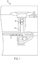
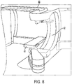
- Figs. 7 and 8 show parts of a particle therapy system 60 containing a particle accelerator mounted on a gantry - the synchrocyclotron contain one or more superconducting coils of the type described herein.
- the gantry (not shown) is steel and has two legs mounted for rotation on two respective bearings that lie on opposite sides of a patient.
- the gantry may include a steel truss, connected to each of the legs, that is long enough to span a treatment area in which the patient lies and that is attached at both ends to the rotating legs of the gantry.
- the particle accelerator may be supported by the steel truss.
- An example of a gantry configuration that may be used is described in U.S. Patent No. 7,728,311 entitled "Charged Particle Radiation Therapy".
- the patient position includes a treatment couch 61.
- An inner gantry 62 moves relative to the treatment couch to direct output 64 of the beam, and to shape the beam, prior to reaching the patient.
- the inner gantry is C-shaped, and its movement coincides with movement of the "outer" gantry, on which the synchrocyclotron is mounted.
- control of the outer and inner gantries, the treatment couch, the beam shaping elements, and the synchrocyclotron to perform a therapy session is achieved by appropriate therapy control electronics (not shown).
- control of the particle therapy system described herein and its various features may be implemented using hardware or a combination of hardware and software.
- a system like the ones described herein may include various controllers and/or processing devices located at various points.
- a central computer may coordinate operation among the various controllers or processing devices.
- the central computer, controllers, and processing devices may execute various software routines to effect control and coordination of testing and calibration.
- System operation can be controlled, at least in part, using one or more computer program products, e.g., one or more computer program tangibly embodied in one or more non-transitory machine-readable media, for execution by, or to control the operation of, one or more data processing apparatus, e.g., a programmable processor, a computer, multiple computers, and/or programmable logic components.
- one or more data processing apparatus e.g., a programmable processor, a computer, multiple computers, and/or programmable logic components.
- a computer program can be written in any form of programming language, including compiled or interpreted languages, and it can be deployed in any form, including as a stand-alone program or as a module, component, subroutine, or other unit suitable for use in a computing environment.
- a computer program can be deployed to be executed on one computer or on multiple computers at one site or distributed across multiple sites and interconnected by a network.
- Actions associated with implementing all or part of the operations of the particle therapy system described herein can be performed by one or more programmable processors executing one or more computer programs to perform the functions described herein. All or part of the operations can be implemented using special purpose logic circuitry, e.g., an FPGA (field programmable gate array) and/or an ASIC (application-specific integrated circuit).
- FPGA field programmable gate array
- ASIC application-specific integrated circuit
- processors suitable for the execution of a computer program include, by way of example, both general and special purpose microprocessors, and any one or more processors of any kind of digital computer.
- a processor will receive instructions and data from a read-only storage area or a random access storage area or both.
- Elements of a computer include one or more processors for executing instructions and one or more storage area devices for storing instructions and data.
- a computer will also include, or be operatively coupled to receive data from, or transfer data to, or both, one or more machine-readable storage media, such as mass PCBs for storing data, e.g., magnetic, magneto-optical disks, or optical disks.
- Non-transitory machine-readable storage media suitable for embodying computer program instructions and data include all forms of non-volatile storage area, including by way of example, semiconductor storage area devices, e.g., EPROM, EEPROM, and flash storage area devices; magnetic disks, e.g., internal hard disks or removable disks; magneto-optical disks; and CD-ROM and DVD-ROM disks.
- semiconductor storage area devices e.g., EPROM, EEPROM, and flash storage area devices
- magnetic disks e.g., internal hard disks or removable disks
- magneto-optical disks e.g., CD-ROM and DVD-ROM disks.
- connection may imply a direct physical connection or a wired or wireless connection that includes intervening components but that nevertheless allows electrical signals to flow between connected components.
- connection involving electrical circuitry that allows signals to flow, unless stated otherwise, is an electrical connection and not necessarily a direct physical connection regardless of whether the word "electrical” is used to modify "connection”.
- any two more of the foregoing implementations may be used in an appropriate combination in an appropriate particle accelerator (e.g., a synchrocyclotron).
- an appropriate particle accelerator e.g., a synchrocyclotron
- individual features of any two more of the foregoing implementations may be used in an appropriate combination.
- the coils described herein are not limited to use with a particle therapy system or to use with the example particle therapy systems described herein.
Landscapes
- Engineering & Computer Science (AREA)
- Health & Medical Sciences (AREA)
- Biomedical Technology (AREA)
- Radiology & Medical Imaging (AREA)
- Pathology (AREA)
- Nuclear Medicine, Radiotherapy & Molecular Imaging (AREA)
- Power Engineering (AREA)
- Life Sciences & Earth Sciences (AREA)
- Animal Behavior & Ethology (AREA)
- General Health & Medical Sciences (AREA)
- Public Health (AREA)
- Veterinary Medicine (AREA)
- Superconductors And Manufacturing Methods Therefor (AREA)
- Particle Accelerators (AREA)
- Radiation-Therapy Devices (AREA)
Claims (15)
- Supraleitende Spule (24), umfassend:integrierte Leiter (30), wobei ein integrierter Leiter umfasst:einen Kern (32), der einen nicht-supraleitenden Mittelstrang umfasst, der Kupfer umfasst; undmindestens sechs Stränge (31a - 31f; 38), die um den Kern herum verkabelt sind, wodurch eine Struktur (35) gebildet wird, wobei jeder der mindestens sechs Stränge supraleitendes Nb3Sn umfasst;wobei jeder der mindestens sechs Stränge einen Querschnitt aufweist, der aus Filamenten (39) zusammengesetzt ist, welche das supraleitende Nb3Sn umfassen, wobei die Filamente innerhalb eines geometrischen Musters vorliegen, das mehrere Wendepunkte (45, 46) umschließt, wobei ein oder mehrere der Filamente an allen oder einigen der mehreren Wendepunkte fehlt bzw. fehlen;wobei der integrierte Leiter des Weiteren einen Kanal (34) umfasst, der elektrisch leitendes Material umfasst; undwobei die Struktur in den Kanal eingepasst ist, und wobei der Kanal mit einem leitfähigen Material gefüllt ist.
- Supraleitende Spule nach Anspruch 1, wobei die mindestens sechs Stränge sechs Stränge sind.
- Supraleitende Spule nach Anspruch 1, wobei das in den Kanal gefüllte leitfähige Material Lot (36) ist.
- Supraleitende Spule nach Anspruch 1, wobei der Mittelstrang nur nicht-supraleitendes Material umfasst, insbesondere Kupfer.
- Supraleitende Spule nach Anspruch 1, wobei der Kern einen Strang mit einem anderen Durchmesser als die mindestens sechs Stränge umfasst.
- Supraleitende Spule nach Anspruch 1, wobei der Kern einen Strang mit demselben Durchmesser wie die mindestens sechs Stränge umfasst.
- Supraleitende Spule nach Anspruch 1, wobei der Kern einen Strang mit einem Durchmesser kleiner als 0,8 mm umfasst.
- Supraleitende Spule nach Anspruch 1, wobei der Kern einen Strang mit einem Durchmesser kleiner als 0,7 mm umfasst.
- Supraleitende Spule nach Anspruch 1, wobei der Kern einen Strang mit einem Durchmesser kleiner als 0,6 mm umfasst.
- Supraleitende Spule nach Anspruch 1, wobei ein oder mehrere der Filamente an jedem der mehreren Wendepunkte fehlt bzw. fehlen.
- Supraleitende Spule nach einem der vorhergehenden Ansprüche, wobei das geometrische Muster innerhalb eines Umfangs (44) des Querschnitts des jeweiligen Strangs angeordnet ist, wobei jeder Strang einen leitfähigen Träger umfasst, der die Filamente umfasst, die sich in Längsrichtung durch den leitfähigen Träger hindurch erstrecken.
- Supraleitende Spule nach einem der vorhergehenden Ansprüche, wobei die Filamente so angeordnet sind, dass die Menge an leitfähigem Träger zwischen jedem Filament und einem Umfang (44) des Querschnitts erhöht ist.
- Supraleitende Spule nach einem der vorhergehenden Ansprüche, wobei das geometrische Muster eine hexagonale Form umfasst, und wobei gegebenenfalls ein Filament an jedem Wendepunkt der hexagonalen Form fehlt.
- Supraleitende Spule nach einem der Ansprüche 11 oder 12, wobei der leitfähige Träger Kupfer umfasst.
- Partikeltherapiesystem (60), umfassend:ein Synchrozyklotron; undeine Gantry (62), auf welcher das Synchrozyklotron montiert ist, um mindestens teilweise um eine Patientenposition herum zu rotieren, um das Synchrozyklotron relativ zu einem Behandlungsbereich des Patienten zu positionieren;wobei das Synchrozyklotron umfasst:einen Magneten, der Spulen umfasst, um elektrischen Strom anzunehmen und ein Magnetfeld in Reaktion auf den elektrischen Strom zu generieren, wobei das Magnetfeld bewirken soll, dass sich die Partikel im Orbit innerhalb eines Hohlraums (57) mit einer Energie bewegen, welche dem elektrischen Strom entspricht, wobei die Spulen supraleitende Spulen gemäß einem der vorhergehenden Ansprüche sind; undeinen Extraktionskanal zum Annehmen der Partikel von dem Hohlraum und zum Ausgeben der von dem Hohlraum angenommenen Partikel.
Applications Claiming Priority (2)
| Application Number | Priority Date | Filing Date | Title |
|---|---|---|---|
| US15/342,632 US20180122544A1 (en) | 2016-11-03 | 2016-11-03 | Superconducting coil configuration |
| PCT/US2017/050565 WO2018125315A2 (en) | 2016-11-03 | 2017-09-07 | Superconducting coil configuration |
Publications (2)
| Publication Number | Publication Date |
|---|---|
| EP3535786A2 EP3535786A2 (de) | 2019-09-11 |
| EP3535786B1 true EP3535786B1 (de) | 2022-04-13 |
Family
ID=61913515
Family Applications (1)
| Application Number | Title | Priority Date | Filing Date |
|---|---|---|---|
| EP17861177.8A Active EP3535786B1 (de) | 2016-11-03 | 2017-09-07 | Supraleitende spulenkonfiguration |
Country Status (5)
| Country | Link |
|---|---|
| US (1) | US20180122544A1 (de) |
| EP (1) | EP3535786B1 (de) |
| JP (2) | JP7058646B2 (de) |
| CN (1) | CN110121791B (de) |
| WO (1) | WO2018125315A2 (de) |
Families Citing this family (4)
| Publication number | Priority date | Publication date | Assignee | Title |
|---|---|---|---|---|
| US20200077507A1 (en) * | 2017-04-21 | 2020-03-05 | Massachusetts Institute Of Technology | DC Constant-Field Synchrotron Providing Inverse Reflection of Charged Particles |
| CN112820470A (zh) * | 2021-01-05 | 2021-05-18 | 中国科学院合肥物质科学研究院 | 一种MgB2CICC导体结构及其制造方法 |
| CN117339125A (zh) * | 2023-08-28 | 2024-01-05 | 迈胜医疗设备有限公司 | 弧形放射治疗设备及其操作方法、粒子加速器 |
| CN119153165B (zh) * | 2024-11-18 | 2025-04-25 | 宝新高分子科技(广州)有限公司 | 一种低烟无卤超导线材及其制作方法 |
Family Cites Families (33)
| Publication number | Priority date | Publication date | Assignee | Title |
|---|---|---|---|---|
| GB1084517A (en) * | 1963-10-15 | 1967-09-27 | Gen Electric | Improvements in a process for providing an improved superconductive alloy |
| US4109374A (en) * | 1975-08-28 | 1978-08-29 | Aluminum Company Of America | Superconductor composite and method of making the same |
| JPS5247396A (en) * | 1975-10-14 | 1977-04-15 | Toshiba Corp | Chemical compound super-conduction wire |
| JPS602728B2 (ja) * | 1975-11-12 | 1985-01-23 | 株式会社日立製作所 | 化合物複合超電導体の製造方法 |
| US4148129A (en) * | 1976-11-01 | 1979-04-10 | Airco, Inc. | Aluminum-stabilized multifilamentary superconductor and method of its manufacture |
| JPS59208704A (ja) * | 1983-05-12 | 1984-11-27 | Toshiba Corp | 化合物超電導コイル |
| US4743713A (en) * | 1984-02-10 | 1988-05-10 | United States Department Of Energy | Aluminum-stabilized NB3SN superconductor |
| JPH0795406B2 (ja) * | 1985-10-30 | 1995-10-11 | 株式会社日立製作所 | 化合物複合超電導導体 |
| JPH05325680A (ja) * | 1992-05-27 | 1993-12-10 | Kobe Steel Ltd | Nb3 Sn系超電導線材の製造方法 |
| ATE150204T1 (de) * | 1992-11-05 | 1997-03-15 | Gec Alsthom T & D Sa | Supraleitende wicklung, insbesondere für strombegrenzer und strombegrenzer mit einer solchen wicklung |
| FR2704980B1 (fr) * | 1993-05-05 | 1995-06-09 | Gec Alsthom Electromec | Interrupteur supraconducteur et application à un chargeur de bobine supraconductrice. |
| US6397454B1 (en) * | 1996-09-26 | 2002-06-04 | American Superconductor Corp. | Decoupling of superconducting elements in high temperature superconducting composites |
| JPH10188692A (ja) * | 1996-10-30 | 1998-07-21 | Furukawa Electric Co Ltd:The | 強制冷却型超電導導体、及びその製造方法、並びに強制冷却型超電導コイルの製造方法 |
| US6510604B1 (en) * | 1997-03-26 | 2003-01-28 | Massachusetts Institute Of Technology | Superconducting cables experiencing reduced strain due to bending |
| JPH11102617A (ja) * | 1997-09-29 | 1999-04-13 | Hitachi Cable Ltd | Nb3Al系化合物超電導体及びその製造方法 |
| US7275301B2 (en) * | 2001-01-30 | 2007-10-02 | Shahin Pourrahimi | Method for reinforcing superconducting coils with high-strength materials |
| US6633215B2 (en) * | 2001-05-01 | 2003-10-14 | Ge Medical Systems Global Technology Company, Llc | Superconducting magnetic resonance imaging magnet assembly and method with reverse wire channel orientation |
| JP4481584B2 (ja) * | 2003-04-11 | 2010-06-16 | 株式会社日立製作所 | 複合シースMgB2超電導線材およびその製造方法 |
| EP2389977A3 (de) | 2005-11-18 | 2012-01-25 | Still River Systems, Inc. | Strahlentherapie mit geladenen Teilchen |
| WO2007130164A2 (en) * | 2006-01-19 | 2007-11-15 | Massachusetts Institute Of Technology | High-field superconducting synchrocyclotron |
| US7718897B2 (en) * | 2006-05-19 | 2010-05-18 | General Electric Company | Low AC loss superconductor for a superconducting magnet and method of making same |
| KR100797405B1 (ko) * | 2006-12-12 | 2008-01-24 | 케이. 에이. 티. (주) | 초전도 선재와 그 제조방법 |
| JP4844458B2 (ja) * | 2007-04-20 | 2011-12-28 | 住友電気工業株式会社 | 超電導コイルおよびそれに用いる超電導導体 |
| US9385295B2 (en) * | 2008-08-08 | 2016-07-05 | Supramagnetics, Inc. | Powder and rod process for forming superconducting wire and method of manufacture thereof |
| DE102008049672B4 (de) * | 2008-09-30 | 2015-11-26 | Bruker Eas Gmbh | Supraleiterverbund mit einem Kern oder mit mehreren Filamenten, die jeweils eine MgB2-Phase aufweisen, sowie Vorprodukt und Verfahren zur Herstellung eines Supraleiterverbundes |
| JP5276542B2 (ja) * | 2009-07-29 | 2013-08-28 | 株式会社日立製作所 | 超電導回路、超電導接続部の作製方法、超電導マグネット、及び、超電導マグネットの製造方法 |
| EP2333793B1 (de) * | 2009-12-09 | 2012-02-08 | Bruker BioSpin AG | Supraleiter mit verbesserter mechanischer Festigkeit |
| JP5519430B2 (ja) * | 2010-06-30 | 2014-06-11 | 株式会社日立製作所 | MgB2超電導線材の製造方法 |
| JP5588303B2 (ja) * | 2010-10-28 | 2014-09-10 | 株式会社Shカッパープロダクツ | Nb3Sn超電導線材の前駆体及びそれを用いたNb3Sn超電導線材 |
| US8938278B2 (en) * | 2011-02-18 | 2015-01-20 | The Regents Of The University Of Colorado | Superconducting cables and methods of making the same |
| JP2013197072A (ja) * | 2012-03-23 | 2013-09-30 | Hitachi Ltd | MgB2超電導多芯線材、超電導ケーブル、超電導マグネット |
| EP2900325B1 (de) * | 2012-09-28 | 2018-01-03 | Mevion Medical Systems, Inc. | Einstellung der energie eines partikelstrahls |
| JP2014137917A (ja) | 2013-01-17 | 2014-07-28 | Hitachi Metals Ltd | Nb3Sn超電導前駆体線材、Nbフィラメント素線、Nb3Sn超電導線材並びにその製造方法 |
-
2016
- 2016-11-03 US US15/342,632 patent/US20180122544A1/en not_active Abandoned
-
2017
- 2017-09-07 JP JP2019523808A patent/JP7058646B2/ja active Active
- 2017-09-07 WO PCT/US2017/050565 patent/WO2018125315A2/en not_active Ceased
- 2017-09-07 EP EP17861177.8A patent/EP3535786B1/de active Active
- 2017-09-07 CN CN201780081940.XA patent/CN110121791B/zh active Active
-
2021
- 2021-03-31 JP JP2021061627A patent/JP2021114610A/ja active Pending
Also Published As
| Publication number | Publication date |
|---|---|
| CN110121791B (zh) | 2023-06-20 |
| JP2019536266A (ja) | 2019-12-12 |
| EP3535786A2 (de) | 2019-09-11 |
| CN110121791A (zh) | 2019-08-13 |
| WO2018125315A2 (en) | 2018-07-05 |
| US20180122544A1 (en) | 2018-05-03 |
| JP2021114610A (ja) | 2021-08-05 |
| WO2018125315A3 (en) | 2018-10-04 |
| JP7058646B2 (ja) | 2022-04-22 |
Similar Documents
| Publication | Publication Date | Title |
|---|---|---|
| KR101976972B1 (ko) | 초전도성 플러터 코일 및 비자성 강화물을 구비하는 등시성 사이클로트론 | |
| JP2021114610A (ja) | 超電導コイル構成 | |
| JP6804581B2 (ja) | アクティブリターンシステムおよび陽子線治療システム | |
| EP1977631B1 (de) | Magnetstruktur für partikelbeschleunigung | |
| CN105103662B (zh) | 磁场再生器 | |
| TWI566645B (zh) | 小型的、冷的、弱聚焦的超導迴旋加速器 | |
| JP2019147008A (ja) | 粒子ビーム走査 | |
| US20200357550A1 (en) | Helical superconducting undulator for 3rd and 4th generation of synchrotron light source and fels | |
| US20250176093A1 (en) | Gantry for a particle therapy system | |
| Schmüser | Superconductivity in high energy particle accelerators | |
| JP5524494B2 (ja) | 磁場形成装置及びこれを用いた粒子加速器 | |
| HK40013652A (en) | Superconducting coil configuration | |
| HK40013652B (en) | Superconducting coil configuration | |
| US20260058043A1 (en) | Bending magnet | |
| Sen et al. | Second generation high gradient quadrupoles for the LHC interaction regions | |
| Arimoto et al. | Study of conduction-cooled superconducting quadrupole magnets combined with dipole correctors for the ILC main linac | |
| Terechkine et al. | Focusing solenoid for the front end of a linear RF accelerator | |
| JP5414312B2 (ja) | コイルシステム及びこれを用いた粒子加速器 | |
| Battle et al. | Optimization of block-coil dipoles for hadron colliders | |
| Priano et al. | A superconducting magnet for a beam delivery system for carbon ion cancer therapy | |
| Tsuchiya et al. | Superconducting final focusing system for KEKB | |
| Manfreda | Numerical analysis of coupled thermal-electromagnetic problems in superconducting cables | |
| Ageev et al. | Tevatron electron lens magnetic system | |
| JP5420932B2 (ja) | コイルシステム及びこれを用いた粒子加速器 | |
| Dahl | Chronicle of superconducting devices at BNL |
Legal Events
| Date | Code | Title | Description |
|---|---|---|---|
| STAA | Information on the status of an ep patent application or granted ep patent |
Free format text: STATUS: UNKNOWN |
|
| STAA | Information on the status of an ep patent application or granted ep patent |
Free format text: STATUS: THE INTERNATIONAL PUBLICATION HAS BEEN MADE |
|
| PUAI | Public reference made under article 153(3) epc to a published international application that has entered the european phase |
Free format text: ORIGINAL CODE: 0009012 |
|
| STAA | Information on the status of an ep patent application or granted ep patent |
Free format text: STATUS: REQUEST FOR EXAMINATION WAS MADE |
|
| 17P | Request for examination filed |
Effective date: 20190529 |
|
| AK | Designated contracting states |
Kind code of ref document: A2 Designated state(s): AL AT BE BG CH CY CZ DE DK EE ES FI FR GB GR HR HU IE IS IT LI LT LU LV MC MK MT NL NO PL PT RO RS SE SI SK SM TR |
|
| AX | Request for extension of the european patent |
Extension state: BA ME |
|
| DAV | Request for validation of the european patent (deleted) | ||
| DAX | Request for extension of the european patent (deleted) | ||
| REG | Reference to a national code |
Ref country code: HK Ref legal event code: DE Ref document number: 40013652 Country of ref document: HK |
|
| STAA | Information on the status of an ep patent application or granted ep patent |
Free format text: STATUS: EXAMINATION IS IN PROGRESS |
|
| 17Q | First examination report despatched |
Effective date: 20200904 |
|
| GRAP | Despatch of communication of intention to grant a patent |
Free format text: ORIGINAL CODE: EPIDOSNIGR1 |
|
| STAA | Information on the status of an ep patent application or granted ep patent |
Free format text: STATUS: GRANT OF PATENT IS INTENDED |
|
| INTG | Intention to grant announced |
Effective date: 20210607 |
|
| GRAJ | Information related to disapproval of communication of intention to grant by the applicant or resumption of examination proceedings by the epo deleted |
Free format text: ORIGINAL CODE: EPIDOSDIGR1 |
|
| STAA | Information on the status of an ep patent application or granted ep patent |
Free format text: STATUS: EXAMINATION IS IN PROGRESS |
|
| GRAS | Grant fee paid |
Free format text: ORIGINAL CODE: EPIDOSNIGR3 |
|
| STAA | Information on the status of an ep patent application or granted ep patent |
Free format text: STATUS: GRANT OF PATENT IS INTENDED |
|
| INTC | Intention to grant announced (deleted) | ||
| GRAP | Despatch of communication of intention to grant a patent |
Free format text: ORIGINAL CODE: EPIDOSNIGR1 |
|
| INTG | Intention to grant announced |
Effective date: 20211112 |
|
| GRAA | (expected) grant |
Free format text: ORIGINAL CODE: 0009210 |
|
| STAA | Information on the status of an ep patent application or granted ep patent |
Free format text: STATUS: THE PATENT HAS BEEN GRANTED |
|
| AK | Designated contracting states |
Kind code of ref document: B1 Designated state(s): AL AT BE BG CH CY CZ DE DK EE ES FI FR GB GR HR HU IE IS IT LI LT LU LV MC MK MT NL NO PL PT RO RS SE SI SK SM TR |
|
| REG | Reference to a national code |
Ref country code: GB Ref legal event code: FG4D |
|
| REG | Reference to a national code |
Ref country code: CH Ref legal event code: EP |
|
| REG | Reference to a national code |
Ref country code: DE Ref legal event code: R096 Ref document number: 602017056059 Country of ref document: DE |
|
| REG | Reference to a national code |
Ref country code: IE Ref legal event code: FG4D |
|
| REG | Reference to a national code |
Ref country code: AT Ref legal event code: REF Ref document number: 1484096 Country of ref document: AT Kind code of ref document: T Effective date: 20220515 |
|
| REG | Reference to a national code |
Ref country code: LT Ref legal event code: MG9D |
|
| REG | Reference to a national code |
Ref country code: NL Ref legal event code: MP Effective date: 20220413 |
|
| REG | Reference to a national code |
Ref country code: AT Ref legal event code: MK05 Ref document number: 1484096 Country of ref document: AT Kind code of ref document: T Effective date: 20220413 |
|
| PG25 | Lapsed in a contracting state [announced via postgrant information from national office to epo] |
Ref country code: NL Free format text: LAPSE BECAUSE OF FAILURE TO SUBMIT A TRANSLATION OF THE DESCRIPTION OR TO PAY THE FEE WITHIN THE PRESCRIBED TIME-LIMIT Effective date: 20220413 |
|
| PG25 | Lapsed in a contracting state [announced via postgrant information from national office to epo] |
Ref country code: SE Free format text: LAPSE BECAUSE OF FAILURE TO SUBMIT A TRANSLATION OF THE DESCRIPTION OR TO PAY THE FEE WITHIN THE PRESCRIBED TIME-LIMIT Effective date: 20220413 Ref country code: PT Free format text: LAPSE BECAUSE OF FAILURE TO SUBMIT A TRANSLATION OF THE DESCRIPTION OR TO PAY THE FEE WITHIN THE PRESCRIBED TIME-LIMIT Effective date: 20220816 Ref country code: NO Free format text: LAPSE BECAUSE OF FAILURE TO SUBMIT A TRANSLATION OF THE DESCRIPTION OR TO PAY THE FEE WITHIN THE PRESCRIBED TIME-LIMIT Effective date: 20220713 Ref country code: LT Free format text: LAPSE BECAUSE OF FAILURE TO SUBMIT A TRANSLATION OF THE DESCRIPTION OR TO PAY THE FEE WITHIN THE PRESCRIBED TIME-LIMIT Effective date: 20220413 Ref country code: HR Free format text: LAPSE BECAUSE OF FAILURE TO SUBMIT A TRANSLATION OF THE DESCRIPTION OR TO PAY THE FEE WITHIN THE PRESCRIBED TIME-LIMIT Effective date: 20220413 Ref country code: GR Free format text: LAPSE BECAUSE OF FAILURE TO SUBMIT A TRANSLATION OF THE DESCRIPTION OR TO PAY THE FEE WITHIN THE PRESCRIBED TIME-LIMIT Effective date: 20220714 Ref country code: FI Free format text: LAPSE BECAUSE OF FAILURE TO SUBMIT A TRANSLATION OF THE DESCRIPTION OR TO PAY THE FEE WITHIN THE PRESCRIBED TIME-LIMIT Effective date: 20220413 Ref country code: ES Free format text: LAPSE BECAUSE OF FAILURE TO SUBMIT A TRANSLATION OF THE DESCRIPTION OR TO PAY THE FEE WITHIN THE PRESCRIBED TIME-LIMIT Effective date: 20220413 Ref country code: BG Free format text: LAPSE BECAUSE OF FAILURE TO SUBMIT A TRANSLATION OF THE DESCRIPTION OR TO PAY THE FEE WITHIN THE PRESCRIBED TIME-LIMIT Effective date: 20220713 Ref country code: AT Free format text: LAPSE BECAUSE OF FAILURE TO SUBMIT A TRANSLATION OF THE DESCRIPTION OR TO PAY THE FEE WITHIN THE PRESCRIBED TIME-LIMIT Effective date: 20220413 |
|
| PGFP | Annual fee paid to national office [announced via postgrant information from national office to epo] |
Ref country code: GB Payment date: 20220927 Year of fee payment: 6 |
|
| REG | Reference to a national code |
Ref country code: DE Ref legal event code: R079 Ref document number: 602017056059 Country of ref document: DE Free format text: PREVIOUS MAIN CLASS: H01L0039140000 Ipc: H10N0060200000 |
|
| PG25 | Lapsed in a contracting state [announced via postgrant information from national office to epo] |
Ref country code: RS Free format text: LAPSE BECAUSE OF FAILURE TO SUBMIT A TRANSLATION OF THE DESCRIPTION OR TO PAY THE FEE WITHIN THE PRESCRIBED TIME-LIMIT Effective date: 20220413 Ref country code: PL Free format text: LAPSE BECAUSE OF FAILURE TO SUBMIT A TRANSLATION OF THE DESCRIPTION OR TO PAY THE FEE WITHIN THE PRESCRIBED TIME-LIMIT Effective date: 20220413 Ref country code: LV Free format text: LAPSE BECAUSE OF FAILURE TO SUBMIT A TRANSLATION OF THE DESCRIPTION OR TO PAY THE FEE WITHIN THE PRESCRIBED TIME-LIMIT Effective date: 20220413 Ref country code: IS Free format text: LAPSE BECAUSE OF FAILURE TO SUBMIT A TRANSLATION OF THE DESCRIPTION OR TO PAY THE FEE WITHIN THE PRESCRIBED TIME-LIMIT Effective date: 20220813 |
|
| PGFP | Annual fee paid to national office [announced via postgrant information from national office to epo] |
Ref country code: FR Payment date: 20220926 Year of fee payment: 6 |
|
| REG | Reference to a national code |
Ref country code: DE Ref legal event code: R097 Ref document number: 602017056059 Country of ref document: DE |
|
| PG25 | Lapsed in a contracting state [announced via postgrant information from national office to epo] |
Ref country code: SM Free format text: LAPSE BECAUSE OF FAILURE TO SUBMIT A TRANSLATION OF THE DESCRIPTION OR TO PAY THE FEE WITHIN THE PRESCRIBED TIME-LIMIT Effective date: 20220413 Ref country code: SK Free format text: LAPSE BECAUSE OF FAILURE TO SUBMIT A TRANSLATION OF THE DESCRIPTION OR TO PAY THE FEE WITHIN THE PRESCRIBED TIME-LIMIT Effective date: 20220413 Ref country code: RO Free format text: LAPSE BECAUSE OF FAILURE TO SUBMIT A TRANSLATION OF THE DESCRIPTION OR TO PAY THE FEE WITHIN THE PRESCRIBED TIME-LIMIT Effective date: 20220413 Ref country code: EE Free format text: LAPSE BECAUSE OF FAILURE TO SUBMIT A TRANSLATION OF THE DESCRIPTION OR TO PAY THE FEE WITHIN THE PRESCRIBED TIME-LIMIT Effective date: 20220413 Ref country code: DK Free format text: LAPSE BECAUSE OF FAILURE TO SUBMIT A TRANSLATION OF THE DESCRIPTION OR TO PAY THE FEE WITHIN THE PRESCRIBED TIME-LIMIT Effective date: 20220413 Ref country code: CZ Free format text: LAPSE BECAUSE OF FAILURE TO SUBMIT A TRANSLATION OF THE DESCRIPTION OR TO PAY THE FEE WITHIN THE PRESCRIBED TIME-LIMIT Effective date: 20220413 |
|
| PLBE | No opposition filed within time limit |
Free format text: ORIGINAL CODE: 0009261 |
|
| STAA | Information on the status of an ep patent application or granted ep patent |
Free format text: STATUS: NO OPPOSITION FILED WITHIN TIME LIMIT |
|
| 26N | No opposition filed |
Effective date: 20230116 |
|
| PG25 | Lapsed in a contracting state [announced via postgrant information from national office to epo] |
Ref country code: AL Free format text: LAPSE BECAUSE OF FAILURE TO SUBMIT A TRANSLATION OF THE DESCRIPTION OR TO PAY THE FEE WITHIN THE PRESCRIBED TIME-LIMIT Effective date: 20220413 |
|
| PG25 | Lapsed in a contracting state [announced via postgrant information from national office to epo] |
Ref country code: MC Free format text: LAPSE BECAUSE OF FAILURE TO SUBMIT A TRANSLATION OF THE DESCRIPTION OR TO PAY THE FEE WITHIN THE PRESCRIBED TIME-LIMIT Effective date: 20220413 |
|
| REG | Reference to a national code |
Ref country code: CH Ref legal event code: PL |
|
| PG25 | Lapsed in a contracting state [announced via postgrant information from national office to epo] |
Ref country code: SI Free format text: LAPSE BECAUSE OF FAILURE TO SUBMIT A TRANSLATION OF THE DESCRIPTION OR TO PAY THE FEE WITHIN THE PRESCRIBED TIME-LIMIT Effective date: 20220413 |
|
| PG25 | Lapsed in a contracting state [announced via postgrant information from national office to epo] |
Ref country code: LU Free format text: LAPSE BECAUSE OF NON-PAYMENT OF DUE FEES Effective date: 20220907 |
|
| PG25 | Lapsed in a contracting state [announced via postgrant information from national office to epo] |
Ref country code: LI Free format text: LAPSE BECAUSE OF NON-PAYMENT OF DUE FEES Effective date: 20220930 Ref country code: IE Free format text: LAPSE BECAUSE OF NON-PAYMENT OF DUE FEES Effective date: 20220907 Ref country code: CH Free format text: LAPSE BECAUSE OF NON-PAYMENT OF DUE FEES Effective date: 20220930 |
|
| P01 | Opt-out of the competence of the unified patent court (upc) registered |
Effective date: 20230630 |
|
| PG25 | Lapsed in a contracting state [announced via postgrant information from national office to epo] |
Ref country code: IT Free format text: LAPSE BECAUSE OF FAILURE TO SUBMIT A TRANSLATION OF THE DESCRIPTION OR TO PAY THE FEE WITHIN THE PRESCRIBED TIME-LIMIT Effective date: 20220413 |
|
| PG25 | Lapsed in a contracting state [announced via postgrant information from national office to epo] |
Ref country code: HU Free format text: LAPSE BECAUSE OF FAILURE TO SUBMIT A TRANSLATION OF THE DESCRIPTION OR TO PAY THE FEE WITHIN THE PRESCRIBED TIME-LIMIT; INVALID AB INITIO Effective date: 20170907 |
|
| PG25 | Lapsed in a contracting state [announced via postgrant information from national office to epo] |
Ref country code: CY Free format text: LAPSE BECAUSE OF FAILURE TO SUBMIT A TRANSLATION OF THE DESCRIPTION OR TO PAY THE FEE WITHIN THE PRESCRIBED TIME-LIMIT Effective date: 20220413 |
|
| GBPC | Gb: european patent ceased through non-payment of renewal fee |
Effective date: 20230907 |
|
| PG25 | Lapsed in a contracting state [announced via postgrant information from national office to epo] |
Ref country code: MK Free format text: LAPSE BECAUSE OF FAILURE TO SUBMIT A TRANSLATION OF THE DESCRIPTION OR TO PAY THE FEE WITHIN THE PRESCRIBED TIME-LIMIT Effective date: 20220413 |
|
| PG25 | Lapsed in a contracting state [announced via postgrant information from national office to epo] |
Ref country code: GB Free format text: LAPSE BECAUSE OF NON-PAYMENT OF DUE FEES Effective date: 20230907 |
|
| PG25 | Lapsed in a contracting state [announced via postgrant information from national office to epo] |
Ref country code: GB Free format text: LAPSE BECAUSE OF NON-PAYMENT OF DUE FEES Effective date: 20230907 Ref country code: FR Free format text: LAPSE BECAUSE OF NON-PAYMENT OF DUE FEES Effective date: 20230930 |
|
| PG25 | Lapsed in a contracting state [announced via postgrant information from national office to epo] |
Ref country code: MT Free format text: LAPSE BECAUSE OF FAILURE TO SUBMIT A TRANSLATION OF THE DESCRIPTION OR TO PAY THE FEE WITHIN THE PRESCRIBED TIME-LIMIT Effective date: 20220413 |
|
| PG25 | Lapsed in a contracting state [announced via postgrant information from national office to epo] |
Ref country code: BG Free format text: LAPSE BECAUSE OF FAILURE TO SUBMIT A TRANSLATION OF THE DESCRIPTION OR TO PAY THE FEE WITHIN THE PRESCRIBED TIME-LIMIT Effective date: 20220413 |
|
| PG25 | Lapsed in a contracting state [announced via postgrant information from national office to epo] |
Ref country code: BG Free format text: LAPSE BECAUSE OF FAILURE TO SUBMIT A TRANSLATION OF THE DESCRIPTION OR TO PAY THE FEE WITHIN THE PRESCRIBED TIME-LIMIT Effective date: 20220413 |
|
| PGFP | Annual fee paid to national office [announced via postgrant information from national office to epo] |
Ref country code: DE Payment date: 20250929 Year of fee payment: 9 |
|
| PGFP | Annual fee paid to national office [announced via postgrant information from national office to epo] |
Ref country code: BE Payment date: 20250929 Year of fee payment: 9 |
|
| PG25 | Lapsed in a contracting state [announced via postgrant information from national office to epo] |
Ref country code: TR Free format text: LAPSE BECAUSE OF FAILURE TO SUBMIT A TRANSLATION OF THE DESCRIPTION OR TO PAY THE FEE WITHIN THE PRESCRIBED TIME-LIMIT Effective date: 20220413 |