EP3535511B1 - Reduktion von mikrobiologischem wachstum in rohren - Google Patents
Reduktion von mikrobiologischem wachstum in rohren Download PDFInfo
- Publication number
- EP3535511B1 EP3535511B1 EP17800428.9A EP17800428A EP3535511B1 EP 3535511 B1 EP3535511 B1 EP 3535511B1 EP 17800428 A EP17800428 A EP 17800428A EP 3535511 B1 EP3535511 B1 EP 3535511B1
- Authority
- EP
- European Patent Office
- Prior art keywords
- pipe
- inner layer
- electrical connector
- electric current
- liquid
- Prior art date
- Legal status (The legal status is an assumption and is not a legal conclusion. Google has not performed a legal analysis and makes no representation as to the accuracy of the status listed.)
- Active
Links
Images



Classifications
-
- F—MECHANICAL ENGINEERING; LIGHTING; HEATING; WEAPONS; BLASTING
- F16—ENGINEERING ELEMENTS AND UNITS; GENERAL MEASURES FOR PRODUCING AND MAINTAINING EFFECTIVE FUNCTIONING OF MACHINES OR INSTALLATIONS; THERMAL INSULATION IN GENERAL
- F16L—PIPES; JOINTS OR FITTINGS FOR PIPES; SUPPORTS FOR PIPES, CABLES OR PROTECTIVE TUBING; MEANS FOR THERMAL INSULATION IN GENERAL
- F16L58/00—Protection of pipes or pipe fittings against corrosion or incrustation
-
- A—HUMAN NECESSITIES
- A61—MEDICAL OR VETERINARY SCIENCE; HYGIENE
- A61L—METHODS OR APPARATUS FOR STERILISING MATERIALS OR OBJECTS IN GENERAL; DISINFECTION, STERILISATION OR DEODORISATION OF AIR; CHEMICAL ASPECTS OF BANDAGES, DRESSINGS, ABSORBENT PADS OR SURGICAL ARTICLES; MATERIALS FOR BANDAGES, DRESSINGS, ABSORBENT PADS OR SURGICAL ARTICLES
- A61L2/00—Disinfection or sterilisation of materials or objects, in general; Accessories therefor
- A61L2/02—Disinfection or sterilisation of materials or objects, in general; Accessories therefor using physical processes
- A61L2/03—Electric current
-
- F—MECHANICAL ENGINEERING; LIGHTING; HEATING; WEAPONS; BLASTING
- F16—ENGINEERING ELEMENTS AND UNITS; GENERAL MEASURES FOR PRODUCING AND MAINTAINING EFFECTIVE FUNCTIONING OF MACHINES OR INSTALLATIONS; THERMAL INSULATION IN GENERAL
- F16L—PIPES; JOINTS OR FITTINGS FOR PIPES; SUPPORTS FOR PIPES, CABLES OR PROTECTIVE TUBING; MEANS FOR THERMAL INSULATION IN GENERAL
- F16L11/00—Hoses, i.e. flexible pipes
- F16L11/04—Hoses, i.e. flexible pipes made of rubber or flexible plastics
- F16L11/12—Hoses, i.e. flexible pipes made of rubber or flexible plastics with arrangements for particular purposes, e.g. specially profiled, with protecting layer, heated, electrically conducting
- F16L11/127—Hoses, i.e. flexible pipes made of rubber or flexible plastics with arrangements for particular purposes, e.g. specially profiled, with protecting layer, heated, electrically conducting electrically conducting
-
- F—MECHANICAL ENGINEERING; LIGHTING; HEATING; WEAPONS; BLASTING
- F16—ENGINEERING ELEMENTS AND UNITS; GENERAL MEASURES FOR PRODUCING AND MAINTAINING EFFECTIVE FUNCTIONING OF MACHINES OR INSTALLATIONS; THERMAL INSULATION IN GENERAL
- F16L—PIPES; JOINTS OR FITTINGS FOR PIPES; SUPPORTS FOR PIPES, CABLES OR PROTECTIVE TUBING; MEANS FOR THERMAL INSULATION IN GENERAL
- F16L9/00—Rigid pipes
- F16L9/12—Rigid pipes of plastics with or without reinforcement
- F16L9/125—Rigid pipes of plastics with or without reinforcement electrically conducting
Definitions
- the proposed technology generally relates to the field of liquid transportation, dispensing, and recycling. In particular, it relates to the reduction of microbiological growth in pipes.
- Microbiological growth and the formation of biofilms on the inside of pipes is a concern in many applications where a liquid is conveyed. Properties of the liquid as such can be influenced by the microbiological growth and make it less suitable for its intended use. Microbiological growth in a pipe may also increase microbiological growth further downstream in equipment that is routinely cleaned from such growth. Microbiological growth can also detach from inside a pipe and cause clogging or damage in downstream equipment. It is also a known problem that microbiological growth on the inside of a pipe can introduce harmful pathogens in the conveyed liquid.
- liquid transportation is water supply by public utilities.
- the pipes are used for long periods of time, typically stretching over several decades. Large quantities of microbiological material can build up in the pipes, which reduces the transport capacity of the pipes.
- the transport may also be over shorter distances, such as in dairy equipment at milk farms.
- Examples of applications using liquid recycling where microbiological growth can be a problem are numerous. For example, it may be a problem in centralized domestic cooling of buildings, recycling of washing liquids in car washes, recycling of cutting fluids in metalworking, recycling of liquids in paper mills, and circulating low-temperature heating systems in buildings.
- liquid dispensing applications are also numerous.
- the microbiological growth may be a problem in beverage dispensing, in particular in dispensing of beer from kegs, in dental equipment, and in domestic water systems, such as showers.
- the latter is a known source of legionella, which may be harmful to people.
- microbiological growth is understood to encompass the formation of a biofilm.
- microbiological growth may be colonies of bacteria.
- a system according to the preamble of claim 1 is known from AT 506089A4 wherein the inner layer of a pipe is formed of an electrically conducting polymer comprising carbon black particles as anti microbiological agent.
- Document US 2013/0202766 A1 discloses a system for preventing microbiological growth in a conduit conveying a liquid, wherein the system comprises a multi-layered pipe wherein discrete electrodes are connected to a power source.
- a system for preventing microbiological growth and/or the formation of a biofilm in a conduit conveying a liquid comprises a multi-layered pipe constituting said conduit and having an inner layer and an outer layer.
- the inner layer covers the complete inside of the pipe and is formed of an electrically conductive polymer material, wherein a liquid in the pipe is in direct contact with the inner layer.
- the outer layer covers at least a portion of the outside of the inner layer and is formed of an electrically insulating polymer material.
- the system further comprises a first electrical connector connecting to the inner layer from outside the pipe and a second electrical connector connecting to the inner layer from outside the pipe, wherein the first electrical connector and the second electrical connector are spaced apart along the pipe.
- the system also comprises an electric power source operationally connected to the first electrical connector and the second electrical connector and configured for supplying an electric current to the inner layer, according to claim 1.
- the multilayered pipe may be a rigid pipe or a flexible hose.
- a method for retrofitting a system for preventing microbiological growth in an existing conduit for conveying a liquid comprises:
- the above object is achieved by a method for preventing microbiological growth in the pipe of a system according to the first aspect, wherein the pipe conveys a liquid.
- the method comprises: supplying an electric current to the inner layer of the pipe with the electric power source.
- a system for preventing microbiological growth and/or the formation of a biofilm in a conduit conveying a liquid wherein the system comprises a single-layered flexible hose constituting said conduit and having a single layer, wherein the single layer is formed of an electrically conductive polymer material, and wherein a liquid in the hose is in direct contact with the single layer.
- the system further comprises a first electrical connector connecting to the single layer from outside the hose and a second electrical connector connecting to the single layer from outside the hose, wherein the first electrical connector and the second electrical connector are spaced apart along the hose.
- the system comprises an electric power source operationally connected to the first electrical connector and the second electrical connector and configured for supplying an electric current to the single layer, and/or for supplying an electric potential over the first electrical connector and the second electrical connector.
- a method for retrofitting a system for preventing microbiological growth in an existing conduit for conveying a liquid.
- the method comprises: providing a system according to the fourth aspect, and providing the hose of the system inside the existing conduit.
- the above object is achieved by a method for preventing microbiological growth in the hose of a system according to the fourth aspect, wherein the hose conveys a liquid.
- the method comprises: supplying an electric current to the single layer of the pipe with the electric power source.
- the technology of the fourth to sixth aspects is particularly useful in applications where the hose is surrounded by electrically insulating material, for example within an existing plastic pipe.
- a beverage dispensing system comprising a tapping station for dispensing the beverage and a beverage conduit for conveying a beverage from a container containing the beverage to the tapping station.
- the beverage dispensing system further comprises a system for preventing microbiological growth according to the first aspect or the fourth aspect, wherein the pipe or hose forms part of the beverage conduit.
- the beverage may be beer and the container may be a keg.
- a liquid is in direct contact with the inner layer means that there is no other material between the inner layer and the liquid.
- the liquid may comprise water and/or water soluble substances, such as sugars, alcohols and salts.
- the main component of the liquid may be water.
- the electric current supplied to the inner layer or single layer may be a direct current.
- the direct current may be below 10 mA, below 1 mA, between 0.1 mA and 1 mA, or between 0.3 mA and 0.7 mA.
- the electric current may be generated at a voltage between the first electrical connector and the second electrical connector that is below 150 V, below 120 V, between 20 V and 100 V, or between 50 V and 70 V.
- the power supply may be configured to supply the direct current to the first electrical connector or the second electrical connector at the here listed voltages between the first electrical connector and the second electrical connector. It has been found that the operating parameters described here reduce microbiological growth, in particular in fast flowing sweet water in distribution mains.
- the power source may be configured for changing the polarity between the first electrical connector and the second electrical connector.
- the changing of the polarity may be random in time or follow a predetermined schedule.
- the polarity may be changed at least once every 12 hours, or at least once every hour. There are indications that the change of polarity will inhibit the microbiological growth.
- the electric current supplied to the inner layer or single layer may be an alternating current.
- the alternating current may be below 10 mA, below 1 mA, between 0.1 mA and 1 mA, or between 0.4 mA and 0.8 mA.
- the alternating current may be supplied at a voltage between the first electrical connector and the second electrical connector that is below 80 V, below 50 V, between 10 V and 50 V, between 20 V and 50 V, or between 30 V and 50 V.
- the power supply may be configured to supply the alternating current to the first electrical connector or the second electrical connector at the here listed voltages between the first electrical connector and the second electrical connector.
- the alternating current may have a frequency between 1 kHz and 5 kHz, or between 1 kHz and 2 kHz. It has been found that the operating parameters described here reduce microbiological growth, in particular in slowly flowing or still sweet water in distribution mains.
- the power source may be further configured for supplying the electric current as a pulsed electric current, both for direct current and alternating current.
- the pulses may have combined pulse length over a period of time that is equal to or less than 50% of the length of the period. It has been found that the microbiological growth is reduced also for pulsed electric currents. The pulsing has the effect of reduced power consumptions, which contributes to lower operation costs.
- the power source may be further configured for changing the polarity between the first electrical connector and the second electrical connector between pulses. There are indications that this will inhibit the microbiological growth.
- the electric current may be supplied at a voltage between the first electrical connector and the second electrical connector that is in the range 1 V and 10 V, 2 V and 8 V, or 3 V and 6. It is contemplated that these voltages will have a sufficient effect on the microbiological growth.
- the electric current supplied to the inner layer or single layer may be a direct current or an alternating current below 10 mA, below 1 mA, between 0.1 mA and 1 mA, or between 0.4 mA and 0.8 mA. Additionally, the electric current may be supplied at a voltage between the first electrical connector and the second electrical connector that is in the range 0.5 kV and 6 kV, 0.5 kV and 4 kV, 0.5 kV and 2 kV, or 0.5 kV and 1 kV. Additionally or alternatively, the electric current may be pulsed.
- the pulses of the electric current may have a pulse length in the range 1 ms and 500 ms, 1 ms and 100 ms, or 1 ms and 10 ms. It is contemplated that these operation parameter will have a significant effect on the microbiological growth.
- the power source may be configured for varying the electric current and/or the electric potential randomly or according to predetermined values.
- the varying of the electric current and/or the electric potential may correspond to relative changes in the range 0.01 to 100, or 0.1 to 10.
- the power source may be configured for varying the electric current and/or the electric potential randomly in time or according to predetermined schedule.
- the varying may result in a change of the electric current and/or the electric potential at least once every 12 hours, or at least once every hour. It is contemplated that the varying of these parameter will disturb the microbiological growth.
- the system may be configured for generating an electric current in the inner layer and an electric current in the liquid, and the electric current in the inner layer may be of the same order of magnitude as the electric current in the liquid, or the electric current in the inner layer may be in the range 0.02 to 50, or 0.1 to 10, times the electric current in the liquid. Additionally or alternatively, the system may be configured for generating an electric current between the inner layer and the liquid corresponding to an electric power in the range 0.01 mW to 500 mW, 0.1 mW to 100 mW, 0.5 mW to 50 mW, or 1 mW to 10 mW per unit area of the inside of the pipe. It should be noted that the parameter determined here depends on the properties of the inner layer and the liquid and can be determined by modeling or experiment.
- the electrically conductive polymer material of the inner layer or the single layer may be a carbon-black filled polymer. Additionally or alternatively to carbon-black, the polymer may be filled with nanotubes, graphene, and/or metal fibers or filaments for providing the electrical conductivity. These materials typically have the advantage that a smaller amount of the material is required than for carbon-black for achieving a desired electrical conductivity.
- the electrically conductive polymer material may comprise or be composed of polyethylene, polypropylene, polyamide, or polyester.
- the polymer material of the electrically insulating polymer material, i.e. the outer layer may comprise or be composed of polyethylene, polypropylene, polyamide, or polyester.
- the electrically conductive polymer material may comprise or be composed of polyethylene, polypropylene, polyamide, or polyester.
- the polymer material of the electrically insulating polymer material, i.e. the outer layer may comprise or be composed of polyethylene, polypropylene, polyamide, or polyesters.
- Carbon black as such may contribute to an increased microbiological growth on the inside of the pipe or hose in the absence of an electric current. However, together with the electric current in the inner layer or single layer, it has been shown that the net effect will be a reduced microbiological growth.
- the resistance between the first electrical connector and the second electrical connector of the of the inner layer multiplied with the inside diameter of the pipe and divided by the length between the first electrical connector and the second electrical connector may be in the range 0.2 k ⁇ to 10 k ⁇ , 0.5 kO to 7 k ⁇ , or 1 k ⁇ to 5 k ⁇ .
- the resistance is determined without a liquid in the pipe. It has been found that pipes with these parameters are suitable for clean to moderately dirty water.
- the first electrical connector and the second electrical connector may be spaced apart by a separation in the range 0.2 m to 50 m, or 1 m to 10 m.
- a multi-layered pipe 10 is provided having an inner layer 12 and an outer layer 14.
- the inner layer 12 is composed of carbon-black filled polyethylene with a 20 weight percentage of carbon-black.
- the outer layer is composed of polyethylene. This means that the inner layer 12 is electrically conductive and the outer layer 14 is electrically insulating.
- the inner layer 12 and the outer layer 14 have been co-extruded in a manner such that the inner layer 12 covers the complete inside 16 of the pipe 10 and the outer layer 14 covers the complete outside of the inner pipe 12, as is shown in Fig. 1c . There is no material between the inner pipe 12 and a liquid conveyed by the pipe 10.
- the polymer of the inner layer 12 and the outer layer 14 is polyethylene, which means that the pipe 10 will have the properties of a hose with respect to manual handling.
- the outer layer 14 is removed at the ends of the pipe 10, thereby making the inner layer 12 accessible from outside the pipe 10, as is shown in Fig. 1b .
- the outer layer 14 is removed at other parts of the pipe 10, for example further in from the ends of the pipes, thus leaving the inner layer 12 covered by the outer layer 14 at the ends of the pipe 10.
- a first electrical connector 18 is attached to the exposed inner layer 12 at one end of the pipe 10, and a second electrical connector 19 is attached to the exposed inner layer 12 at the other end of the pipe 10. Both connectors are tightened around the inner layer in a similar manner as a hose clamp is tightened, thus ensuring a good electrical connection between each of the connectors and the inner layer 12.
- An electric power source 20 is provided that is operationally connected to the first connector 18 via a first cable 22 and to the second connector 19 via a second cable 24.
- the electric power source 20 When installed in an application and with a liquid running through the pipe 10, the electric power source 20 is set to supply a direct current in the inner layer 12 that is between 0.3 mA and 0.7 mA by way of the electric circuit established with the first connector 18, the second connector 19, the first cable 22, and the second cable 24.
- the electric power source 20 is also set to generate a stable potential in the range 50 V and 70 V between the first connector 18 and the second connector 19.
- the electric power source 20 is set to supply an alternating current in the inner layer 12 that is between 0.4 mA and 0.8 mA. Additionally or alternatively, the electric power source 20 is also set to generate a stable potential in the range 50 V and 70 V between the first connector 18 and the second connector 19.
- the electric power source 20 is operated to supply a continuous electric current to the inner layer 12.
- the electric current is pulsed or intermittently operated.
- the electric current is supplied in a cycle alternating between one week of electric current supply and one week without electric current supply, thus effectively having a combined pulse length over a period of time that is 50% of the length of the period.
- FIG. 2 An embodiment of the proposed system 8 is shown in Fig. 2 .
- the system 8 is installed in a liquid transportation application 40. It has all the features of the system 8 described above in relation to Fig. 1 .
- the pipe 10 is connected to a liquid supply 26, for example public water mains.
- the pipe 10 is connected to a liquid recipient 28, such as the water inlet at a domestic or industrial building, or another section of the public water mains.
- Fig. 3 schematically illustrates an embodiment of the proposed system 8 in a liquid dispensing application.
- the system 8 has all the features described above in relation to Fig. 1 .
- the pipe 10 is connected to a liquid supply 30, for example a hot-water pipe in a domestic building.
- the pipe 10 is connected to a liquid dispenser 32, such as a shower in a domestic or public building.
- FIG. 4 Another embodiment of the proposed system 8 is shown in Fig. 4 .
- the system 8 is installed in a liquid recycling application 44. It has all the features of the system 8 described above in relation to Fig. 1 .
- the pipe 10 is connected to liquid recycler 28, such as the heat exchanger, the circulation pump, and the radiators of a low-temperature heating system of a building.
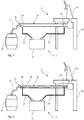
- FIG. 5 An embodiment of a beverage dispensing system 6 is schematically illustrated in Fig. 5 .
- the dispensing system 6 has a liquid dispenser or tapping station for the beverage in the form of a beer tap 32 attached to a bar counter 34. It further has a beverage conduit 36 for conveying a beverage from a liquid supply or container containing the beverage in the form of a beer keg 30.
- a system 8 for preventing microbiological growth having the features of the embodiment described above in relation to Fig. 1 forms part of the dispensing system 6.
- the pipe 10 constitutes a portion of the beverage conduit 6. At one end, the pipe 10 is connected to the beer keg 30 via a beverage hose 37. At its other end, the pipe 10 is connected to the beer tap 32.
- the electric power source 20 is operated as described above in relation to Fig. 1 , microbiological growth is prevented in the pipe 10.
- FIG. 6 Another embodiment of a beverage dispensing system 6 is schematically illustrated in Fig. 6 .
- the dispensing system 6 has a liquid dispenser or tapping station for the beverage in the form of a beer tap 32 attached to a bar counter 34.
- a system 8 for preventing microbiological growth forms part of the dispensing system 6.
- the system 8 differs in that the pipe 10 is a hose.
- the dispensing system 6 has an existing conduit 38 in the form of a rigid pipe 38.
- the hose 10 has been retrofitted in the rigid pipe 38 by the insertion of the hose 10 through the receiving end of the rigid pipe 38 and by connecting the hose 10 to the beer tap 32.
- the hose 10 is connected to a beer keg 30 via a beverage hose 37.
- the hose 10 forms part of a beverage conduit 36 conveying beer from the keg 30 to the beer tap 32.
- the investigation was divided into two periods, the first period covering weeks 1 to 10 and the second period covering weeks 10 to 25.
- Microbiological growth was monitored weekly by the taking of samples of the biofilm from the inner walls of the pipes. The samples were cultivated for 48 hours and the number of bacteria colonies was then calculated in each sample and used to represent the microbiological growth in the corresponding setup.
- the microbiological growth was allowed to settle on the inner walls and allowed to adjust to the environment inside the pipes. No conclusive results were achieved in the first period. The three setups were then moved and connected to the public mains at another point before the second period of investigation started.
- the results of the second period are shown in Fig. 7 .
- the weeks are indicated on the abscissa and the number of counted bacteria is indicated on the ordinate.
- the left bar represents the measurement from the first setup, i.e. with a single layer polyethylene pipe
- the middle bar represents the measurement from the second setup, i.e. with an inner conductive layer without an electric current
- the right bar represents the measurement from the third setup, i.e. with an inner conductive layer with an electric current. It should be noted that no sampling was performed in the weeks without any bars.
- the microbiological growth in the second setup was greater than in the third setup, thus showing that the supplied electric current reduces the microbiological growth. It is contemplated that the high initial counts of the second and third setups is a result of an initial adaption to the environment inside the pipes with carbon-black in the inner layer.
Landscapes
- Engineering & Computer Science (AREA)
- General Engineering & Computer Science (AREA)
- Mechanical Engineering (AREA)
- Health & Medical Sciences (AREA)
- Epidemiology (AREA)
- Life Sciences & Earth Sciences (AREA)
- Animal Behavior & Ethology (AREA)
- General Health & Medical Sciences (AREA)
- Public Health (AREA)
- Veterinary Medicine (AREA)
- Rigid Pipes And Flexible Pipes (AREA)
- Water Treatment By Electricity Or Magnetism (AREA)
Claims (15)
- System (8) zur Verhinderung von mikrobiologischem Wachstum in einer Leitung, die eine Flüssigkeit führt, wobei das System (8) Folgendes umfasst:- ein mehrschichtiges Rohr (10), das die Leitung bildet und eine Innenschicht (12) und eine Außenschicht (14) aufweist, wobei die Innenschicht (12) die vollständige Innenseite (16) des Rohres (10) bedeckt und aus einem elektrisch leitfähigen Polymermaterial gebildet ist, wobei eine Flüssigkeit in dem Rohr (10) in direktem Kontakt mit der Innenschicht (12) ist und wobei die Außenschicht (14) zumindest einen Abschnitt der Außenseite der Innenschicht (12) bedeckt und aus einem elektrisch isolierenden Polymermaterial gebildet ist, dadurch gekennzeichnet, dassdas System darüber hinaus folgendes umfasst:- einen ersten elektrischen Verbinder (18), der sich mit der Innenschicht (12) von außerhalb des Rohres (10) verbindet, und einen zweiten elektrischen Verbinder (19), der sich mit der Innenschicht (12) von außerhalb des Rohres (10) verbindet, wobei der erste elektrische Verbinder (18) und der zweite elektrische Verbinder (19) entlang des Rohres (10) beabstandet sind, und- eine elektrische Leistungsquelle (20), die mit dem ersten elektrischen Verbinder (18) und dem zweiten elektrischen Verbinder (19) wirkverbunden und konfiguriert ist, um der Innenschicht (12) einen elektrischen Strom zuzuführen.
- System (8) nach Anspruch 1, wobei der elektrische Strom ein Gleichstrom ist.
- System (8) nach Anspruch 2, wobei der elektrische Strom unter 10 mA, unter 1 mA, zwischen 0,1 mA und 1 mA oder zwischen 0,3 mA und 0,7 mA ist.
- System (8) nach Anspruch 2 oder 3, wobei der elektrische Strom bei einer Spannung zwischen dem ersten elektrischen Verbinder (18) und dem zweiten elektrischen Verbinder (19) zugeführt wird, die unter 150 V, unter 120 V, zwischen 20 V und 100 V oder zwischen 50 V und 70 V ist.
- System (8) nach Anspruch 1, wobei der elektrische Strom ein Wechselstrom ist.
- System (8) nach Anspruch 5, wobei der elektrische Strom unter 10 mA, unter 1 mA, zwischen 0,1 mA und 1 mA oder zwischen 0,4 mA und 0,8 mA ist.
- System (8) nach Anspruch 5 oder 6, wobei der elektrische Strom bei einer Spannung zwischen dem ersten elektrischen Verbinder (18) und dem zweiten elektrischen Verbinder (19) zugeführt wird, die unter 80 V, unter 50 V, zwischen 10 V und 50 V, zwischen 20 V und 50 V oder zwischen 30 V und 50 V ist.
- System (8) nach einem der Ansprüche 5-7, wobei der Wechselstrom eine Frequenz zwischen 1 kHz und 5 kHz aufweist.
- System (8) nach einem der Ansprüche 1-8, wobei die Stromquelle (20) ferner konfiguriert ist, um einen gepulsten elektrischen Strom zuzuführen.
- System (8) nach Anspruch 9, wobei die Impulse eine kombinierte Impulslänge über einen Zeitraum aufweisen, der gleich oder weniger als 50 % der Länge des Zeitraumes ist.
- System (8) nach einem der Ansprüche 1-10, wobei das elektrisch leitfähige Polymermaterial der Innenschicht (12) mit Ruß gefülltes Polyethylen ist.
- System (8) nach einem der Ansprüche 1-11, wobei das mehrschichtige Rohr (10) ein flexibler Schlauch ist.
- System (8) nach Anspruch 12, wobei das elektrisch leitfähige Polymermaterial der Innenschicht (12) mit Ruß gefülltes Polyethylen ist.
- Verfahren zum Nachrüsten eines Systems (8) zum Verhindern von mikrobiologischem Wachstum in einer vorhandenen Leitung zum Führen einer Flüssigkeit, wobei das Verfahren Folgendes umfasst:- Bereitstellen eines Systems (8) nach einem der Ansprüche 1-13,- Bereitstellen des Rohres (10) innerhalb der vorhandenen Leitung.
- Verfahren zum Verhindern von mikrobiologischem Wachstum in einem Rohr (10) unter Anwendung von einem System (8) nach einem der Ansprüche 1-13, wobei das Rohr (10) eine Flüssigkeit führt und das Verfahren Folgendes umfasst: Zuführen eines elektrischen Stroms zu der Innenschicht (12) des Rohres (10) mit der elektrischen Leistungsquelle (20).
Priority Applications (1)
| Application Number | Priority Date | Filing Date | Title |
|---|---|---|---|
| PL17800428T PL3535511T3 (pl) | 2016-11-01 | 2017-11-01 | Zmniejszanie obrostu mikrobiologicznego w rurach |
Applications Claiming Priority (2)
| Application Number | Priority Date | Filing Date | Title |
|---|---|---|---|
| EP16196711.2A EP3315841B1 (de) | 2016-11-01 | 2016-11-01 | Reduktion von mikrobiologischem wachstum in rohren |
| PCT/EP2017/077973 WO2018083127A1 (en) | 2016-11-01 | 2017-11-01 | Reduction of microbiological growth in pipes |
Publications (2)
| Publication Number | Publication Date |
|---|---|
| EP3535511A1 EP3535511A1 (de) | 2019-09-11 |
| EP3535511B1 true EP3535511B1 (de) | 2021-12-29 |
Family
ID=57249697
Family Applications (2)
| Application Number | Title | Priority Date | Filing Date |
|---|---|---|---|
| EP16196711.2A Active EP3315841B1 (de) | 2016-11-01 | 2016-11-01 | Reduktion von mikrobiologischem wachstum in rohren |
| EP17800428.9A Active EP3535511B1 (de) | 2016-11-01 | 2017-11-01 | Reduktion von mikrobiologischem wachstum in rohren |
Family Applications Before (1)
| Application Number | Title | Priority Date | Filing Date |
|---|---|---|---|
| EP16196711.2A Active EP3315841B1 (de) | 2016-11-01 | 2016-11-01 | Reduktion von mikrobiologischem wachstum in rohren |
Country Status (8)
| Country | Link |
|---|---|
| US (1) | US11454345B2 (de) |
| EP (2) | EP3315841B1 (de) |
| JP (1) | JP7048626B2 (de) |
| CN (1) | CN109906335B (de) |
| DK (1) | DK3535511T3 (de) |
| ES (1) | ES2910927T3 (de) |
| PL (1) | PL3535511T3 (de) |
| WO (1) | WO2018083127A1 (de) |
Families Citing this family (7)
| Publication number | Priority date | Publication date | Assignee | Title |
|---|---|---|---|---|
| ES3009835T3 (en) | 2019-10-07 | 2025-04-01 | Alfa Laval Corp Ab | Prevention of microbiological growth in heat exchangers |
| EP3805689A1 (de) * | 2019-10-07 | 2021-04-14 | EPFF Electrical Pipe For Fluid transport AB | Verhinderung von mikrobiologischem wachstum in wärmetauschern |
| US20210299399A1 (en) * | 2020-03-31 | 2021-09-30 | Peter Barrett | Active / passive anti-pathogen endotracheal tube |
| EP4677157A1 (de) * | 2023-03-09 | 2026-01-14 | Soleno Inc. | Verfahren und systeme zur kontrolle der eisenochre-proliferation in einem rohr |
| CN116576339A (zh) * | 2023-04-27 | 2023-08-11 | 浙江大学 | 一种抑制微生物污垢生成的管道及方法 |
| EP4516889A1 (de) * | 2023-08-29 | 2025-03-05 | EPFF Electrical Pipe For Fluid transport AB | Verhinderung von mikrobiologischem wachstum in verarbeitungssystemen |
| EP4517098A1 (de) * | 2023-08-29 | 2025-03-05 | EPFF Electrical Pipe For Fluid transport AB | Verhinderung von mikrobiologischem wachstum in verarbeitungseinrichtungen |
Citations (1)
| Publication number | Priority date | Publication date | Assignee | Title |
|---|---|---|---|---|
| US20130202766A1 (en) * | 2012-02-06 | 2013-08-08 | Elmedtech, LLC | Composition, Methods and Devices for Reduction of Cells in a Volume of Matter Using Low Voltage High Electric Field (LVHEF) Electrical Energy |
Family Cites Families (19)
| Publication number | Priority date | Publication date | Assignee | Title |
|---|---|---|---|---|
| GB471318A (en) * | 1937-03-30 | 1937-09-01 | Karl A Zimmerer Mfg Company In | Improvements relating to apparatus, for preventing beer settling |
| JP2701462B2 (ja) * | 1989-06-21 | 1998-01-21 | 大阪瓦斯株式会社 | 温水配管用多層パイプ |
| US5645697A (en) * | 1992-09-25 | 1997-07-08 | Middleton; David Leslie Phillip | Preventing contaminant build-up in beer lines |
| JP3962846B2 (ja) * | 1997-10-22 | 2007-08-22 | アタカ大機株式会社 | 防汚方法および防汚装置 |
| JPH11147598A (ja) * | 1997-11-12 | 1999-06-02 | Leslie Philip Middleton David | 飲料搬送管の細菌の成長防止、除去装置およびその方法 |
| JP2002282810A (ja) * | 2001-03-27 | 2002-10-02 | Daiki Engineering Kk | 防汚装置 |
| EP1273436A1 (de) * | 2001-07-05 | 2003-01-08 | Atofina Research S.A. | Glänzende Schläuche und Röhren |
| US7094381B1 (en) * | 2003-01-08 | 2006-08-22 | James Michael Overton | Device for destroying microbes in a fluid |
| JP2005074256A (ja) * | 2003-08-28 | 2005-03-24 | Jonan Kk | 配水管への有機物の付着及び堆積防止方法並びに装置 |
| US20080053550A1 (en) * | 2006-08-30 | 2008-03-06 | Dayco Products, Llc | Multilayer hose construction |
| GB2442011B (en) * | 2006-09-20 | 2011-09-14 | Cambridge Scient Solutions Ltd | Fluid conveying conduit |
| EP2052743A1 (de) * | 2007-10-25 | 2009-04-29 | Carlsberg Breweries A/S | Getränkesterilisationsvorrichtung |
| GB0800538D0 (en) * | 2008-01-11 | 2008-02-20 | Crompton Technology Group Ltd | Fuel pipes with controlled resistivity |
| AT506089B1 (de) * | 2008-03-03 | 2009-06-15 | Ke Kelit Kunststoffwerk Gmbh | Formkörper aus einem polymer, insbesondere rohr |
| WO2010071588A1 (en) * | 2008-12-19 | 2010-06-24 | Laplast Ab | A pipe and a method for reducing biofilms |
| WO2012128771A1 (en) * | 2011-03-24 | 2012-09-27 | Empire Technology Development Llc | Fluid treatment method and system using flowing generator to treat water |
| JP6270285B2 (ja) * | 2012-08-28 | 2018-01-31 | エコスペック グローバル テクノロジー ピーティーイー エルティーディー. | 水と接触する基材への水生生物の付着を防止するシステム及び方法 |
| CN103865307B (zh) * | 2014-02-10 | 2016-08-24 | 海南大学 | 一种利用高压脉冲电场防海水及淡水生物污损的方法 |
| WO2016109020A1 (en) * | 2014-12-30 | 2016-07-07 | Exxonmobil Upstream Research Company | Algae-based method of inhibiting corrosion in offshore flexible pipes |
-
2016
- 2016-11-01 EP EP16196711.2A patent/EP3315841B1/de active Active
-
2017
- 2017-11-01 WO PCT/EP2017/077973 patent/WO2018083127A1/en not_active Ceased
- 2017-11-01 DK DK17800428.9T patent/DK3535511T3/da active
- 2017-11-01 PL PL17800428T patent/PL3535511T3/pl unknown
- 2017-11-01 ES ES17800428T patent/ES2910927T3/es active Active
- 2017-11-01 US US16/345,594 patent/US11454345B2/en active Active
- 2017-11-01 EP EP17800428.9A patent/EP3535511B1/de active Active
- 2017-11-01 CN CN201780068279.9A patent/CN109906335B/zh active Active
- 2017-11-01 JP JP2019545856A patent/JP7048626B2/ja active Active
Patent Citations (1)
| Publication number | Priority date | Publication date | Assignee | Title |
|---|---|---|---|---|
| US20130202766A1 (en) * | 2012-02-06 | 2013-08-08 | Elmedtech, LLC | Composition, Methods and Devices for Reduction of Cells in a Volume of Matter Using Low Voltage High Electric Field (LVHEF) Electrical Energy |
Also Published As
| Publication number | Publication date |
|---|---|
| JP2019535512A (ja) | 2019-12-12 |
| US20190249815A1 (en) | 2019-08-15 |
| EP3315841A1 (de) | 2018-05-02 |
| PL3535511T3 (pl) | 2022-05-09 |
| DK3535511T3 (da) | 2022-04-04 |
| EP3315841B1 (de) | 2019-03-27 |
| ES2910927T3 (es) | 2022-05-17 |
| CN109906335A (zh) | 2019-06-18 |
| JP7048626B2 (ja) | 2022-04-05 |
| CN109906335B (zh) | 2021-03-19 |
| EP3535511A1 (de) | 2019-09-11 |
| US11454345B2 (en) | 2022-09-27 |
| WO2018083127A1 (en) | 2018-05-11 |
Similar Documents
| Publication | Publication Date | Title |
|---|---|---|
| EP3535511B1 (de) | Reduktion von mikrobiologischem wachstum in rohren | |
| US7407589B2 (en) | Method and apparatus for preventing scale deposits and removing contaminants from fluid columns | |
| US10317096B2 (en) | Ion generation device | |
| CN101119936B (zh) | 流体处理方法和设备 | |
| US6706196B2 (en) | Method and apparatus for preventing scale deposits and removing contaminants from fluid columns | |
| US8480890B2 (en) | Method and apparatus for preventing scale deposits and removing contaminants from fluid columns | |
| DE102008064038A1 (de) | Vorrichtung und Verfahren zur Detektion von Belägen | |
| EP1075453B1 (de) | Vorrichtung und methode zur molekularen polarisation in wasser | |
| CN105090668B (zh) | 传输管道的智能加热系统 | |
| JP2009528467A (ja) | 枝管の追加を監視する給水管システム及びその方法 | |
| ES2538982T3 (es) | Conducto para la transportación de fluidos y método para prevenir la contaminación de fluidos | |
| US20030057086A1 (en) | High voltage electrostatic field for treatment of flowing liquids | |
| CN101530940B (zh) | 设计成用于切割在火花腐蚀加工机上使用过的线的装置 | |
| CA3044362C (en) | Water conditioner with variable frequency electromagnetic field | |
| US20170336011A1 (en) | Station for heating fluids flowing through a network of submarine pipelines | |
| EP3230493A1 (de) | Verfahren und vorrichtung zur korrosionsverhinderung | |
| US11673816B2 (en) | Systems and methods for treating harmful biological contaminants in HVAC systems | |
| EP2370725B1 (de) | Rohrleitung und verahren zur minimierung von mikrobiellem bewuchs | |
| EP2753436A2 (de) | Verfahren und vorrichtung zur behandlung von leitungen | |
| US20220009800A1 (en) | Trans-channel reaction cell and method of use | |
| CN102436871A (zh) | 一种用于中频电源电流互感器与设备的连接导线 | |
| GB2409503A (en) | A beer line conditioning apparatus | |
| GB2550107A (en) | Method and apparatus for treating conduits | |
| DE10222581A1 (de) | Steuerung zur Überwachung eines elektrischen Heizgerätes | |
| TWM360730U (en) | Gapless electrostatic field generator and water cooling tower with such a gapless electrostatic field generator |
Legal Events
| Date | Code | Title | Description |
|---|---|---|---|
| STAA | Information on the status of an ep patent application or granted ep patent |
Free format text: STATUS: UNKNOWN |
|
| STAA | Information on the status of an ep patent application or granted ep patent |
Free format text: STATUS: THE INTERNATIONAL PUBLICATION HAS BEEN MADE |
|
| PUAI | Public reference made under article 153(3) epc to a published international application that has entered the european phase |
Free format text: ORIGINAL CODE: 0009012 |
|
| STAA | Information on the status of an ep patent application or granted ep patent |
Free format text: STATUS: REQUEST FOR EXAMINATION WAS MADE |
|
| 17P | Request for examination filed |
Effective date: 20190417 |
|
| AK | Designated contracting states |
Kind code of ref document: A1 Designated state(s): AL AT BE BG CH CY CZ DE DK EE ES FI FR GB GR HR HU IE IS IT LI LT LU LV MC MK MT NL NO PL PT RO RS SE SI SK SM TR |
|
| AX | Request for extension of the european patent |
Extension state: BA ME |
|
| DAV | Request for validation of the european patent (deleted) | ||
| DAX | Request for extension of the european patent (deleted) | ||
| GRAP | Despatch of communication of intention to grant a patent |
Free format text: ORIGINAL CODE: EPIDOSNIGR1 |
|
| STAA | Information on the status of an ep patent application or granted ep patent |
Free format text: STATUS: GRANT OF PATENT IS INTENDED |
|
| INTG | Intention to grant announced |
Effective date: 20200319 |
|
| GRAJ | Information related to disapproval of communication of intention to grant by the applicant or resumption of examination proceedings by the epo deleted |
Free format text: ORIGINAL CODE: EPIDOSDIGR1 |
|
| STAA | Information on the status of an ep patent application or granted ep patent |
Free format text: STATUS: REQUEST FOR EXAMINATION WAS MADE |
|
| INTC | Intention to grant announced (deleted) | ||
| STAA | Information on the status of an ep patent application or granted ep patent |
Free format text: STATUS: EXAMINATION IS IN PROGRESS |
|
| 17Q | First examination report despatched |
Effective date: 20200910 |
|
| GRAP | Despatch of communication of intention to grant a patent |
Free format text: ORIGINAL CODE: EPIDOSNIGR1 |
|
| STAA | Information on the status of an ep patent application or granted ep patent |
Free format text: STATUS: GRANT OF PATENT IS INTENDED |
|
| INTG | Intention to grant announced |
Effective date: 20210721 |
|
| GRAS | Grant fee paid |
Free format text: ORIGINAL CODE: EPIDOSNIGR3 |
|
| GRAA | (expected) grant |
Free format text: ORIGINAL CODE: 0009210 |
|
| STAA | Information on the status of an ep patent application or granted ep patent |
Free format text: STATUS: THE PATENT HAS BEEN GRANTED |
|
| AK | Designated contracting states |
Kind code of ref document: B1 Designated state(s): AL AT BE BG CH CY CZ DK EE ES FI GR HR HU IE IS IT LI LT LU LV MC MK MT NL NO PL PT RO RS SE SI SK SM TR |
|
| RBV | Designated contracting states (corrected) |
Designated state(s): AL AT BE BG CH CY CZ DK EE ES FI GR HR HU IE IS IT LI LT LU LV MC MK MT NL NO PL PT RO RS SE SI SK SM TR |
|
| REG | Reference to a national code |
Ref country code: DE Ref legal event code: R108 |
|
| REG | Reference to a national code |
Ref country code: CH Ref legal event code: EP |
|
| REG | Reference to a national code |
Ref country code: AT Ref legal event code: REF Ref document number: 1458924 Country of ref document: AT Kind code of ref document: T Effective date: 20220115 |
|
| REG | Reference to a national code |
Ref country code: IE Ref legal event code: FG4D |
|
| REG | Reference to a national code |
Ref country code: FI Ref legal event code: FGE |
|
| REG | Reference to a national code |
Ref country code: DK Ref legal event code: T3 Effective date: 20220329 |
|
| REG | Reference to a national code |
Ref country code: LT Ref legal event code: MG9D |
|
| REG | Reference to a national code |
Ref country code: NL Ref legal event code: FP |
|
| REG | Reference to a national code |
Ref country code: SE Ref legal event code: TRGR |
|
| PG25 | Lapsed in a contracting state [announced via postgrant information from national office to epo] |
Ref country code: RS Free format text: LAPSE BECAUSE OF FAILURE TO SUBMIT A TRANSLATION OF THE DESCRIPTION OR TO PAY THE FEE WITHIN THE PRESCRIBED TIME-LIMIT Effective date: 20211229 Ref country code: LT Free format text: LAPSE BECAUSE OF FAILURE TO SUBMIT A TRANSLATION OF THE DESCRIPTION OR TO PAY THE FEE WITHIN THE PRESCRIBED TIME-LIMIT Effective date: 20211229 Ref country code: BG Free format text: LAPSE BECAUSE OF FAILURE TO SUBMIT A TRANSLATION OF THE DESCRIPTION OR TO PAY THE FEE WITHIN THE PRESCRIBED TIME-LIMIT Effective date: 20220329 |
|
| REG | Reference to a national code |
Ref country code: NO Ref legal event code: T2 Effective date: 20211229 |
|
| REG | Reference to a national code |
Ref country code: AT Ref legal event code: MK05 Ref document number: 1458924 Country of ref document: AT Kind code of ref document: T Effective date: 20211229 |
|
| REG | Reference to a national code |
Ref country code: ES Ref legal event code: FG2A Ref document number: 2910927 Country of ref document: ES Kind code of ref document: T3 Effective date: 20220517 |
|
| PG25 | Lapsed in a contracting state [announced via postgrant information from national office to epo] |
Ref country code: LV Free format text: LAPSE BECAUSE OF FAILURE TO SUBMIT A TRANSLATION OF THE DESCRIPTION OR TO PAY THE FEE WITHIN THE PRESCRIBED TIME-LIMIT Effective date: 20211229 Ref country code: HR Free format text: LAPSE BECAUSE OF FAILURE TO SUBMIT A TRANSLATION OF THE DESCRIPTION OR TO PAY THE FEE WITHIN THE PRESCRIBED TIME-LIMIT Effective date: 20211229 Ref country code: GR Free format text: LAPSE BECAUSE OF FAILURE TO SUBMIT A TRANSLATION OF THE DESCRIPTION OR TO PAY THE FEE WITHIN THE PRESCRIBED TIME-LIMIT Effective date: 20220330 |
|
| PG25 | Lapsed in a contracting state [announced via postgrant information from national office to epo] |
Ref country code: SM Free format text: LAPSE BECAUSE OF FAILURE TO SUBMIT A TRANSLATION OF THE DESCRIPTION OR TO PAY THE FEE WITHIN THE PRESCRIBED TIME-LIMIT Effective date: 20211229 Ref country code: SK Free format text: LAPSE BECAUSE OF FAILURE TO SUBMIT A TRANSLATION OF THE DESCRIPTION OR TO PAY THE FEE WITHIN THE PRESCRIBED TIME-LIMIT Effective date: 20211229 Ref country code: RO Free format text: LAPSE BECAUSE OF FAILURE TO SUBMIT A TRANSLATION OF THE DESCRIPTION OR TO PAY THE FEE WITHIN THE PRESCRIBED TIME-LIMIT Effective date: 20211229 Ref country code: PT Free format text: LAPSE BECAUSE OF FAILURE TO SUBMIT A TRANSLATION OF THE DESCRIPTION OR TO PAY THE FEE WITHIN THE PRESCRIBED TIME-LIMIT Effective date: 20220429 Ref country code: EE Free format text: LAPSE BECAUSE OF FAILURE TO SUBMIT A TRANSLATION OF THE DESCRIPTION OR TO PAY THE FEE WITHIN THE PRESCRIBED TIME-LIMIT Effective date: 20211229 Ref country code: CZ Free format text: LAPSE BECAUSE OF FAILURE TO SUBMIT A TRANSLATION OF THE DESCRIPTION OR TO PAY THE FEE WITHIN THE PRESCRIBED TIME-LIMIT Effective date: 20211229 |
|
| PG25 | Lapsed in a contracting state [announced via postgrant information from national office to epo] |
Ref country code: AT Free format text: LAPSE BECAUSE OF FAILURE TO SUBMIT A TRANSLATION OF THE DESCRIPTION OR TO PAY THE FEE WITHIN THE PRESCRIBED TIME-LIMIT Effective date: 20211229 |
|
| PG25 | Lapsed in a contracting state [announced via postgrant information from national office to epo] |
Ref country code: IS Free format text: LAPSE BECAUSE OF FAILURE TO SUBMIT A TRANSLATION OF THE DESCRIPTION OR TO PAY THE FEE WITHIN THE PRESCRIBED TIME-LIMIT Effective date: 20220429 |
|
| PG25 | Lapsed in a contracting state [announced via postgrant information from national office to epo] |
Ref country code: AL Free format text: LAPSE BECAUSE OF FAILURE TO SUBMIT A TRANSLATION OF THE DESCRIPTION OR TO PAY THE FEE WITHIN THE PRESCRIBED TIME-LIMIT Effective date: 20211229 |
|
| PLBE | No opposition filed within time limit |
Free format text: ORIGINAL CODE: 0009261 |
|
| STAA | Information on the status of an ep patent application or granted ep patent |
Free format text: STATUS: NO OPPOSITION FILED WITHIN TIME LIMIT |
|
| 26N | No opposition filed |
Effective date: 20220930 |
|
| PGFP | Annual fee paid to national office [announced via postgrant information from national office to epo] |
Ref country code: LU Payment date: 20221116 Year of fee payment: 6 |
|
| PG25 | Lapsed in a contracting state [announced via postgrant information from national office to epo] |
Ref country code: SI Free format text: LAPSE BECAUSE OF FAILURE TO SUBMIT A TRANSLATION OF THE DESCRIPTION OR TO PAY THE FEE WITHIN THE PRESCRIBED TIME-LIMIT Effective date: 20211229 |
|
| P01 | Opt-out of the competence of the unified patent court (upc) registered |
Effective date: 20230521 |
|
| PG25 | Lapsed in a contracting state [announced via postgrant information from national office to epo] |
Ref country code: MC Free format text: LAPSE BECAUSE OF FAILURE TO SUBMIT A TRANSLATION OF THE DESCRIPTION OR TO PAY THE FEE WITHIN THE PRESCRIBED TIME-LIMIT Effective date: 20211229 |
|
| REG | Reference to a national code |
Ref country code: BE Ref legal event code: MM Effective date: 20221130 |
|
| PG25 | Lapsed in a contracting state [announced via postgrant information from national office to epo] |
Ref country code: IE Free format text: LAPSE BECAUSE OF NON-PAYMENT OF DUE FEES Effective date: 20221101 |
|
| PG25 | Lapsed in a contracting state [announced via postgrant information from national office to epo] |
Ref country code: BE Free format text: LAPSE BECAUSE OF NON-PAYMENT OF DUE FEES Effective date: 20221130 |
|
| PG25 | Lapsed in a contracting state [announced via postgrant information from national office to epo] |
Ref country code: HU Free format text: LAPSE BECAUSE OF FAILURE TO SUBMIT A TRANSLATION OF THE DESCRIPTION OR TO PAY THE FEE WITHIN THE PRESCRIBED TIME-LIMIT; INVALID AB INITIO Effective date: 20171101 |
|
| PG25 | Lapsed in a contracting state [announced via postgrant information from national office to epo] |
Ref country code: CY Free format text: LAPSE BECAUSE OF FAILURE TO SUBMIT A TRANSLATION OF THE DESCRIPTION OR TO PAY THE FEE WITHIN THE PRESCRIBED TIME-LIMIT Effective date: 20211229 |
|
| PG25 | Lapsed in a contracting state [announced via postgrant information from national office to epo] |
Ref country code: MK Free format text: LAPSE BECAUSE OF FAILURE TO SUBMIT A TRANSLATION OF THE DESCRIPTION OR TO PAY THE FEE WITHIN THE PRESCRIBED TIME-LIMIT Effective date: 20211229 |
|
| PG25 | Lapsed in a contracting state [announced via postgrant information from national office to epo] |
Ref country code: LU Free format text: LAPSE BECAUSE OF NON-PAYMENT OF DUE FEES Effective date: 20231101 |
|
| PG25 | Lapsed in a contracting state [announced via postgrant information from national office to epo] |
Ref country code: LU Free format text: LAPSE BECAUSE OF NON-PAYMENT OF DUE FEES Effective date: 20231101 |
|
| PG25 | Lapsed in a contracting state [announced via postgrant information from national office to epo] |
Ref country code: MT Free format text: LAPSE BECAUSE OF FAILURE TO SUBMIT A TRANSLATION OF THE DESCRIPTION OR TO PAY THE FEE WITHIN THE PRESCRIBED TIME-LIMIT Effective date: 20211229 |
|
| REG | Reference to a national code |
Ref country code: CH Ref legal event code: U11 Free format text: ST27 STATUS EVENT CODE: U-0-0-U10-U11 (AS PROVIDED BY THE NATIONAL OFFICE) Effective date: 20251201 |
|
| PG25 | Lapsed in a contracting state [announced via postgrant information from national office to epo] |
Ref country code: TR Free format text: LAPSE BECAUSE OF FAILURE TO SUBMIT A TRANSLATION OF THE DESCRIPTION OR TO PAY THE FEE WITHIN THE PRESCRIBED TIME-LIMIT Effective date: 20211229 |
|
| PGFP | Annual fee paid to national office [announced via postgrant information from national office to epo] |
Ref country code: NL Payment date: 20251121 Year of fee payment: 9 |
|
| PGFP | Annual fee paid to national office [announced via postgrant information from national office to epo] |
Ref country code: NO Payment date: 20251120 Year of fee payment: 9 |
|
| PGFP | Annual fee paid to national office [announced via postgrant information from national office to epo] |
Ref country code: FI Payment date: 20251118 Year of fee payment: 9 Ref country code: DK Payment date: 20251120 Year of fee payment: 9 Ref country code: IT Payment date: 20251121 Year of fee payment: 9 |
|
| PGFP | Annual fee paid to national office [announced via postgrant information from national office to epo] |
Ref country code: CH Payment date: 20251201 Year of fee payment: 9 Ref country code: SE Payment date: 20251121 Year of fee payment: 9 |
|
| PGFP | Annual fee paid to national office [announced via postgrant information from national office to epo] |
Ref country code: PL Payment date: 20251005 Year of fee payment: 9 |
|
| PGFP | Annual fee paid to national office [announced via postgrant information from national office to epo] |
Ref country code: ES Payment date: 20251208 Year of fee payment: 9 |