EP3534840B2 - Transkatheter-klappenprothese - Google Patents
Transkatheter-klappenprothese Download PDFInfo
- Publication number
- EP3534840B2 EP3534840B2 EP17829277.7A EP17829277A EP3534840B2 EP 3534840 B2 EP3534840 B2 EP 3534840B2 EP 17829277 A EP17829277 A EP 17829277A EP 3534840 B2 EP3534840 B2 EP 3534840B2
- Authority
- EP
- European Patent Office
- Prior art keywords
- tubular body
- valve
- fabric
- buffer component
- outflow end
- Prior art date
- Legal status (The legal status is an assumption and is not a legal conclusion. Google has not performed a legal analysis and makes no representation as to the accuracy of the status listed.)
- Active
Links
Images


Classifications
-
- A—HUMAN NECESSITIES
- A61—MEDICAL OR VETERINARY SCIENCE; HYGIENE
- A61F—FILTERS IMPLANTABLE INTO BLOOD VESSELS; PROSTHESES; DEVICES PROVIDING PATENCY TO, OR PREVENTING COLLAPSING OF, TUBULAR STRUCTURES OF THE BODY, e.g. STENTS; ORTHOPAEDIC, NURSING OR CONTRACEPTIVE DEVICES; FOMENTATION; TREATMENT OR PROTECTION OF EYES OR EARS; BANDAGES, DRESSINGS OR ABSORBENT PADS; FIRST-AID KITS
- A61F2/00—Filters implantable into blood vessels; Prostheses, i.e. artificial substitutes or replacements for parts of the body; Appliances for connecting them with the body; Devices providing patency to, or preventing collapsing of, tubular structures of the body, e.g. stents
- A61F2/02—Prostheses implantable into the body
- A61F2/24—Heart valves ; Vascular valves, e.g. venous valves; Heart implants, e.g. passive devices for improving the function of the native valve or the heart muscle; Transmyocardial revascularisation [TMR] devices; Valves implantable in the body
- A61F2/2412—Heart valves ; Vascular valves, e.g. venous valves; Heart implants, e.g. passive devices for improving the function of the native valve or the heart muscle; Transmyocardial revascularisation [TMR] devices; Valves implantable in the body with soft flexible valve members, e.g. tissue valves shaped like natural valves
- A61F2/2418—Scaffolds therefor, e.g. support stents
-
- A—HUMAN NECESSITIES
- A61—MEDICAL OR VETERINARY SCIENCE; HYGIENE
- A61F—FILTERS IMPLANTABLE INTO BLOOD VESSELS; PROSTHESES; DEVICES PROVIDING PATENCY TO, OR PREVENTING COLLAPSING OF, TUBULAR STRUCTURES OF THE BODY, e.g. STENTS; ORTHOPAEDIC, NURSING OR CONTRACEPTIVE DEVICES; FOMENTATION; TREATMENT OR PROTECTION OF EYES OR EARS; BANDAGES, DRESSINGS OR ABSORBENT PADS; FIRST-AID KITS
- A61F2/00—Filters implantable into blood vessels; Prostheses, i.e. artificial substitutes or replacements for parts of the body; Appliances for connecting them with the body; Devices providing patency to, or preventing collapsing of, tubular structures of the body, e.g. stents
- A61F2/02—Prostheses implantable into the body
- A61F2/24—Heart valves ; Vascular valves, e.g. venous valves; Heart implants, e.g. passive devices for improving the function of the native valve or the heart muscle; Transmyocardial revascularisation [TMR] devices; Valves implantable in the body
- A61F2/2412—Heart valves ; Vascular valves, e.g. venous valves; Heart implants, e.g. passive devices for improving the function of the native valve or the heart muscle; Transmyocardial revascularisation [TMR] devices; Valves implantable in the body with soft flexible valve members, e.g. tissue valves shaped like natural valves
- A61F2/2415—Manufacturing methods
-
- A—HUMAN NECESSITIES
- A61—MEDICAL OR VETERINARY SCIENCE; HYGIENE
- A61F—FILTERS IMPLANTABLE INTO BLOOD VESSELS; PROSTHESES; DEVICES PROVIDING PATENCY TO, OR PREVENTING COLLAPSING OF, TUBULAR STRUCTURES OF THE BODY, e.g. STENTS; ORTHOPAEDIC, NURSING OR CONTRACEPTIVE DEVICES; FOMENTATION; TREATMENT OR PROTECTION OF EYES OR EARS; BANDAGES, DRESSINGS OR ABSORBENT PADS; FIRST-AID KITS
- A61F2/00—Filters implantable into blood vessels; Prostheses, i.e. artificial substitutes or replacements for parts of the body; Appliances for connecting them with the body; Devices providing patency to, or preventing collapsing of, tubular structures of the body, e.g. stents
- A61F2/02—Prostheses implantable into the body
- A61F2/24—Heart valves ; Vascular valves, e.g. venous valves; Heart implants, e.g. passive devices for improving the function of the native valve or the heart muscle; Transmyocardial revascularisation [TMR] devices; Valves implantable in the body
- A61F2/2442—Annuloplasty rings or inserts for correcting the valve shape; Implants for improving the function of a native heart valve
- A61F2/2454—Means for preventing inversion of the valve leaflets, e.g. chordae tendineae prostheses
- A61F2/2457—Chordae tendineae prostheses
-
- A—HUMAN NECESSITIES
- A61—MEDICAL OR VETERINARY SCIENCE; HYGIENE
- A61F—FILTERS IMPLANTABLE INTO BLOOD VESSELS; PROSTHESES; DEVICES PROVIDING PATENCY TO, OR PREVENTING COLLAPSING OF, TUBULAR STRUCTURES OF THE BODY, e.g. STENTS; ORTHOPAEDIC, NURSING OR CONTRACEPTIVE DEVICES; FOMENTATION; TREATMENT OR PROTECTION OF EYES OR EARS; BANDAGES, DRESSINGS OR ABSORBENT PADS; FIRST-AID KITS
- A61F2/00—Filters implantable into blood vessels; Prostheses, i.e. artificial substitutes or replacements for parts of the body; Appliances for connecting them with the body; Devices providing patency to, or preventing collapsing of, tubular structures of the body, e.g. stents
- A61F2/82—Devices providing patency to, or preventing collapsing of, tubular structures of the body, e.g. stents
- A61F2002/828—Means for connecting a plurality of stents allowing flexibility of the whole structure
-
- A—HUMAN NECESSITIES
- A61—MEDICAL OR VETERINARY SCIENCE; HYGIENE
- A61F—FILTERS IMPLANTABLE INTO BLOOD VESSELS; PROSTHESES; DEVICES PROVIDING PATENCY TO, OR PREVENTING COLLAPSING OF, TUBULAR STRUCTURES OF THE BODY, e.g. STENTS; ORTHOPAEDIC, NURSING OR CONTRACEPTIVE DEVICES; FOMENTATION; TREATMENT OR PROTECTION OF EYES OR EARS; BANDAGES, DRESSINGS OR ABSORBENT PADS; FIRST-AID KITS
- A61F2220/00—Fixations or connections for prostheses classified in groups A61F2/00 - A61F2/26 or A61F2/82 or A61F9/00 or A61F11/00 or subgroups thereof
- A61F2220/0025—Connections or couplings between prosthetic parts, e.g. between modular parts; Connecting elements
- A61F2220/0075—Connections or couplings between prosthetic parts, e.g. between modular parts; Connecting elements sutured, ligatured or stitched, retained or tied with a rope, string, thread, wire or cable
-
- A—HUMAN NECESSITIES
- A61—MEDICAL OR VETERINARY SCIENCE; HYGIENE
- A61F—FILTERS IMPLANTABLE INTO BLOOD VESSELS; PROSTHESES; DEVICES PROVIDING PATENCY TO, OR PREVENTING COLLAPSING OF, TUBULAR STRUCTURES OF THE BODY, e.g. STENTS; ORTHOPAEDIC, NURSING OR CONTRACEPTIVE DEVICES; FOMENTATION; TREATMENT OR PROTECTION OF EYES OR EARS; BANDAGES, DRESSINGS OR ABSORBENT PADS; FIRST-AID KITS
- A61F2230/00—Geometry of prostheses classified in groups A61F2/00 - A61F2/26 or A61F2/82 or A61F9/00 or A61F11/00 or subgroups thereof
- A61F2230/0002—Two-dimensional shapes, e.g. cross-sections
- A61F2230/0004—Rounded shapes, e.g. with rounded corners
- A61F2230/001—Figure-8-shaped, e.g. hourglass-shaped
-
- A—HUMAN NECESSITIES
- A61—MEDICAL OR VETERINARY SCIENCE; HYGIENE
- A61F—FILTERS IMPLANTABLE INTO BLOOD VESSELS; PROSTHESES; DEVICES PROVIDING PATENCY TO, OR PREVENTING COLLAPSING OF, TUBULAR STRUCTURES OF THE BODY, e.g. STENTS; ORTHOPAEDIC, NURSING OR CONTRACEPTIVE DEVICES; FOMENTATION; TREATMENT OR PROTECTION OF EYES OR EARS; BANDAGES, DRESSINGS OR ABSORBENT PADS; FIRST-AID KITS
- A61F2230/00—Geometry of prostheses classified in groups A61F2/00 - A61F2/26 or A61F2/82 or A61F9/00 or A61F11/00 or subgroups thereof
- A61F2230/0002—Two-dimensional shapes, e.g. cross-sections
- A61F2230/0028—Shapes in the form of latin or greek characters
- A61F2230/005—Rosette-shaped, e.g. star-shaped
-
- A—HUMAN NECESSITIES
- A61—MEDICAL OR VETERINARY SCIENCE; HYGIENE
- A61F—FILTERS IMPLANTABLE INTO BLOOD VESSELS; PROSTHESES; DEVICES PROVIDING PATENCY TO, OR PREVENTING COLLAPSING OF, TUBULAR STRUCTURES OF THE BODY, e.g. STENTS; ORTHOPAEDIC, NURSING OR CONTRACEPTIVE DEVICES; FOMENTATION; TREATMENT OR PROTECTION OF EYES OR EARS; BANDAGES, DRESSINGS OR ABSORBENT PADS; FIRST-AID KITS
- A61F2230/00—Geometry of prostheses classified in groups A61F2/00 - A61F2/26 or A61F2/82 or A61F9/00 or A61F11/00 or subgroups thereof
- A61F2230/0002—Two-dimensional shapes, e.g. cross-sections
- A61F2230/0028—Shapes in the form of latin or greek characters
- A61F2230/0054—V-shaped
-
- A—HUMAN NECESSITIES
- A61—MEDICAL OR VETERINARY SCIENCE; HYGIENE
- A61F—FILTERS IMPLANTABLE INTO BLOOD VESSELS; PROSTHESES; DEVICES PROVIDING PATENCY TO, OR PREVENTING COLLAPSING OF, TUBULAR STRUCTURES OF THE BODY, e.g. STENTS; ORTHOPAEDIC, NURSING OR CONTRACEPTIVE DEVICES; FOMENTATION; TREATMENT OR PROTECTION OF EYES OR EARS; BANDAGES, DRESSINGS OR ABSORBENT PADS; FIRST-AID KITS
- A61F2230/00—Geometry of prostheses classified in groups A61F2/00 - A61F2/26 or A61F2/82 or A61F9/00 or A61F11/00 or subgroups thereof
- A61F2230/0063—Three-dimensional shapes
- A61F2230/0073—Quadric-shaped
- A61F2230/0078—Quadric-shaped hyperboloidal
-
- A—HUMAN NECESSITIES
- A61—MEDICAL OR VETERINARY SCIENCE; HYGIENE
- A61F—FILTERS IMPLANTABLE INTO BLOOD VESSELS; PROSTHESES; DEVICES PROVIDING PATENCY TO, OR PREVENTING COLLAPSING OF, TUBULAR STRUCTURES OF THE BODY, e.g. STENTS; ORTHOPAEDIC, NURSING OR CONTRACEPTIVE DEVICES; FOMENTATION; TREATMENT OR PROTECTION OF EYES OR EARS; BANDAGES, DRESSINGS OR ABSORBENT PADS; FIRST-AID KITS
- A61F2250/00—Special features of prostheses classified in groups A61F2/00 - A61F2/26 or A61F2/82 or A61F9/00 or A61F11/00 or subgroups thereof
- A61F2250/0014—Special features of prostheses classified in groups A61F2/00 - A61F2/26 or A61F2/82 or A61F9/00 or A61F11/00 or subgroups thereof having different values of a given property or geometrical feature, e.g. mechanical property or material property, at different locations within the same prosthesis
- A61F2250/0029—Special features of prostheses classified in groups A61F2/00 - A61F2/26 or A61F2/82 or A61F9/00 or A61F11/00 or subgroups thereof having different values of a given property or geometrical feature, e.g. mechanical property or material property, at different locations within the same prosthesis differing in bending or flexure capacity
-
- A—HUMAN NECESSITIES
- A61—MEDICAL OR VETERINARY SCIENCE; HYGIENE
- A61F—FILTERS IMPLANTABLE INTO BLOOD VESSELS; PROSTHESES; DEVICES PROVIDING PATENCY TO, OR PREVENTING COLLAPSING OF, TUBULAR STRUCTURES OF THE BODY, e.g. STENTS; ORTHOPAEDIC, NURSING OR CONTRACEPTIVE DEVICES; FOMENTATION; TREATMENT OR PROTECTION OF EYES OR EARS; BANDAGES, DRESSINGS OR ABSORBENT PADS; FIRST-AID KITS
- A61F2250/00—Special features of prostheses classified in groups A61F2/00 - A61F2/26 or A61F2/82 or A61F9/00 or A61F11/00 or subgroups thereof
- A61F2250/0014—Special features of prostheses classified in groups A61F2/00 - A61F2/26 or A61F2/82 or A61F9/00 or A61F11/00 or subgroups thereof having different values of a given property or geometrical feature, e.g. mechanical property or material property, at different locations within the same prosthesis
- A61F2250/0036—Special features of prostheses classified in groups A61F2/00 - A61F2/26 or A61F2/82 or A61F9/00 or A61F11/00 or subgroups thereof having different values of a given property or geometrical feature, e.g. mechanical property or material property, at different locations within the same prosthesis differing in thickness
-
- A—HUMAN NECESSITIES
- A61—MEDICAL OR VETERINARY SCIENCE; HYGIENE
- A61F—FILTERS IMPLANTABLE INTO BLOOD VESSELS; PROSTHESES; DEVICES PROVIDING PATENCY TO, OR PREVENTING COLLAPSING OF, TUBULAR STRUCTURES OF THE BODY, e.g. STENTS; ORTHOPAEDIC, NURSING OR CONTRACEPTIVE DEVICES; FOMENTATION; TREATMENT OR PROTECTION OF EYES OR EARS; BANDAGES, DRESSINGS OR ABSORBENT PADS; FIRST-AID KITS
- A61F2250/00—Special features of prostheses classified in groups A61F2/00 - A61F2/26 or A61F2/82 or A61F9/00 or A61F11/00 or subgroups thereof
- A61F2250/0014—Special features of prostheses classified in groups A61F2/00 - A61F2/26 or A61F2/82 or A61F9/00 or A61F11/00 or subgroups thereof having different values of a given property or geometrical feature, e.g. mechanical property or material property, at different locations within the same prosthesis
- A61F2250/0039—Special features of prostheses classified in groups A61F2/00 - A61F2/26 or A61F2/82 or A61F9/00 or A61F11/00 or subgroups thereof having different values of a given property or geometrical feature, e.g. mechanical property or material property, at different locations within the same prosthesis differing in diameter
-
- A—HUMAN NECESSITIES
- A61—MEDICAL OR VETERINARY SCIENCE; HYGIENE
- A61F—FILTERS IMPLANTABLE INTO BLOOD VESSELS; PROSTHESES; DEVICES PROVIDING PATENCY TO, OR PREVENTING COLLAPSING OF, TUBULAR STRUCTURES OF THE BODY, e.g. STENTS; ORTHOPAEDIC, NURSING OR CONTRACEPTIVE DEVICES; FOMENTATION; TREATMENT OR PROTECTION OF EYES OR EARS; BANDAGES, DRESSINGS OR ABSORBENT PADS; FIRST-AID KITS
- A61F2250/00—Special features of prostheses classified in groups A61F2/00 - A61F2/26 or A61F2/82 or A61F9/00 or A61F11/00 or subgroups thereof
- A61F2250/0014—Special features of prostheses classified in groups A61F2/00 - A61F2/26 or A61F2/82 or A61F9/00 or A61F11/00 or subgroups thereof having different values of a given property or geometrical feature, e.g. mechanical property or material property, at different locations within the same prosthesis
- A61F2250/0048—Special features of prostheses classified in groups A61F2/00 - A61F2/26 or A61F2/82 or A61F9/00 or A61F11/00 or subgroups thereof having different values of a given property or geometrical feature, e.g. mechanical property or material property, at different locations within the same prosthesis differing in mechanical expandability, e.g. in mechanical, self- or balloon expandability
Definitions
- Heart valve diseases affect approximately 300,000 people worldwide each year. Those diseases translate in abnormal leaflet tissue, for example, excess tissue growth, tissue degradation/rupture, or tissue hardening/calcifying. Those diseases may also translate in abnormal tissue position through the cardiac cycle of the heart, for example, annular dilation or ventricular reshaping. Such abnormal leaflet tissue and abnormal tissue position may lead to degradation in valve function including leakage/blood backflow (valve insufficiency) or a resistance to blood forward flow (valve stenosis).
- abnormal leaflet tissue and abnormal tissue position may lead to degradation in valve function including leakage/blood backflow (valve insufficiency) or a resistance to blood forward flow (valve stenosis).
- a valve replacement procedure is a minimally invasive surgical procedure in which a patient's defective heart valve is repaired.
- the abnormal leaflet tissue or the abnormal tissue position may be repaired in order to restore operability of the heart valve.
- a valve prosthesis is delivered to the patient's native heart valve without removing the patient's native heart valve. Instead, the valve prosthesis replaces the functions of the native heart valve.
- WO 2015/128741 A2 describes a heart valve system according to the preamble of claim 1.
- the invention provides a heart valve system according to claim 1. Further embodiments are described in the dependent claims.
- the disclosed embodiments are directed toward a transcatheter valve prosthesis 1 for functional replacement of a patient's native heart valve in a connection channel.
- the patient's native heart valve may be, for example, a mitral valve or a tricuspid valve.
- Transcatheter valve prosthesis 1 may serve as an artificial replacement valve for the patient's native valve.
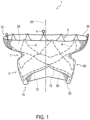
- transcatheter valve prosthesis 1 includes a radially, self-expandable tubular body 5 having an inflow end 10 and an outflow end 15 (according to the direction of blood flow when the system is implanted in a patient) extending along longitudinal axis 20.
- tubular body 5 may be balloon expandable.
- Tubular body 5 may include a circumferential portion 3, formed of a mesh-like structure, which is delivered within a patient via a delivery catheter.
- the mesh-like structure of tubular body 5 may include a plurality of struts 9 formed of a superalloy and/or a shape memory alloy including nickel, titanium, and/or precious metals (e.g., gold).
- tubular body 5 is formed of Nitinol. In other embodiments, tubular body 5 is formed of polymers including polyvinyl-chloride, polystyrene, polypropylene, and/or another polymer. For example, tubular body 5 may be formed of one or more bioabsorbable polymers.
- Tubular body 5 may be generally cylindrical in shape. Outflow end 15 of tubular body 5 may also include a frustoconical shape that slopes radially outward. Alternatively, outflow end 15 of tubular body 5 may be tapered inward. Furthermore, Figures 1-16 show various configurations of struts 9 of tubular body 5. Thus, it is within the scope of the present disclosure to further modify the structure and configuration of struts 9.
- one or more retaining rings 4 may be connected to circumferential portion 3 at inflow end 10 of tubular body 5. Retaining rings 4 may aid in the delivery and removal of valve prosthesis 1 within a patient.
- Tubular body 5 may include an outer preformed groove 7 that is open to the radial outside of tubular body 5.
- Preformed groove 7 may be an indentation in the mesh-like structure of tubular body 5 that defines a channel. As shown in Figure 1 , preformed groove 7 may extend around an entire outer circumference of tubular body 5. In other embodiments, preformed groove 7 may extend less than the entire outer circumference of tubular body 5.
- Preformed groove 7 may be a continuous, non-interrupted groove, or may be an interrupted groove having, for example, two or more groove portions.
- preformed groove 7 may be located at an axial distance, along axis 20, from both inflow end 10 and outflow end 15 of tubular body 5. Thus, preformed groove 7 may be axially spaced apart from proximal-most and distal-most ends of tubular body 5.
- Preformed groove 7 may be delimited by projections (not shown) that protrude outward from tubular body 5.
- tubular body 5 may include a first set of projections that are disposed above preformed groove 7, in an inflow direction, and a second set of projections that are disposed below preformed groove 7, in an outflow direction.
- the first and second set of projections may surround a top and bottom portion of preformed groove 7.
- the first and second set of projections may be directed toward each other.
- the first and second set of projections may be members configured to pierce tissue such as, for example, spikes, triangular projections, barbs, etc.
- a tubular fabric 25 may be disposed on an outer surface of tubular body 5 such that fabric 25 has an inflow end 30 and an outflow end 35. Fabric 25 may cover an entire outer surface of circumferential portion 3 of tubular body 5, or only a portion of the outer surface of circumferential portion 3. As shown in Figure 1 , fabric 25 may be disposed within preformed groove 7 such that fabric 25 follows the contours of preformed groove 7. Fabric 25 may be slack or tightly disposed on tubular body 5. As discussed further below, a trapping member 150 may be disposed around tubular body 5. Fabric 25 may be disposed on tubular body 25 such that it is in a slack state until trapping member 150 is disposed around tubular body 25. Thus, trapping member 150 may cause fabric 25 to be moved into preformed groove such that fabric 25 is in a tensioned state.
- Fabric 25 may be formed of a polymer material including, for example, polyester fabric (e.g., DACRON ® or other PTFE graft material). Additionally, or alternatively, fabric 25 may be formed of pericardium and/or a metal mesh material (e.g. a metal mesh formed of Nitinol). In some embodiments, fabric 25 may include one or more segments of material. For example, fabric 25 may include two, four, or six segments of material. The segments may be spaced apart, providing gaps between adjacent segments. Alternatively or in addition, some or all adjacent segments may overlap. Fabric 25 may include one layer of material or multiple layers of materials. In some embodiments, fabric 25 may include a coating or a liner.
- Fabric 25 may be attached to tubular body 5 through any known securing mechanism.
- fabric 25 and tubular body 5 may be secured through an adhesive and/or sutures.
- fabric 25 may be configured to assume a deployed, expanded configuration and a contracted, reduced configuration with tubular body 5.
- fabric 25 may be expanded and contracted based on the state of tubular body 5.
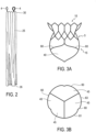
- Tubular body 5 may be coupled to an artificial heart valve 40 such that at least a portion of valve 40 extends distally beyond outflow end 15 of tubular body 5 ( Figure 3A ).
- valve 40 may include a plurality of valve leaflets 45.
- Valve 40 may serve as an artificial replacement for a patient's native heart valve (for example, a mitral and/or a tricuspid valve).
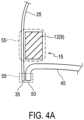
- Tubular body 5 may be coupled to valve 40 such that an outer circumferential edge 50 of leaflets 45 is directly connected to outflow end 35 of fabric 25 ( Figures 4A and 4B ).
- valve leaflets 45 may extend distally of outflow end 15 of tubular body 5 in an outflow direction.
- Valve leaflets 45 may also be distal of preformed groove 7 in an outflow direction.
- Outer circumferential edge 50 of leaflets 45 may axially overlap with outflow end 35 of fabric 25 such that outer circumferential edge 50 is connected to outflow end 35 with one or more sutures 55.
- outer circumferential edge 50 may be connected to outflow end 35 with any suitable securing mechanism, such as, for example, an adhesive, clips, clamps, etc.
- tubular body 5 may be directly connected to fabric 25 such that struts 9 of tubular body 5 are connected to fabric 25 with one or more sutures 55 ( Figure 4A ).
- struts 9 may be connected to fabric 25 with any suitable securing mechanism, such as, for example, an adhesive, clips, clamps, etc.
- valve leaflets 45 are not directly connected to tubular body 5. Therefore, valve 40 is also not directly connected to tubular body 5. Instead, valve 40 is indirectly connected to tubular body 5 through fabric 25.
- outer circumferential edge 50 of valve leaflets 45 may be disposed on an inflow side of valve 40.
- outer circumferential edge 50 of valve leaflets 45 may be directly connected to outflow end 35 of fabric 25 such that outer circumferential edge 50 of valve leaflets 45 axially overlaps with outflow end 35 of fabric 25 in order to provide the direct connection between valve 40 and fabric 25.
- struts 9 of tubular body 5 that are directly connected to fabric 25 may be struts 12 located at outflow end 15 of tubular body 5 ( Figures 1 and 4A ). Struts 12 may axially overlap with fabric 25. Thus, struts 12 may provide the direct connection between tubular body 5 and fabric 25.
- connection between fabric 25 and struts 12 of tubular body 5 may be located closer to inflow end 10 of tubular body 5 than the connection between fabric 25 and outer circumferential edge 50 of valve leaflets 45 ( Figures 4A and 4B ).
- connection between fabric 25 and tubular body 5 may be proximal of the connection between fabric 25 and valve 40 ( Figures 4A and 4B ). It is further contemplated that the connection between fabric 25 and tubular body 5 may be located at the same axial position as the connection between fabric 25 and valve 40 such that the connections axially overlap.
- outer circumferential edge 50 of valve leaflets 45 may be disposed distal of, in an outflow direction, of struts 12.
- outer circumferential edge 50 may be disposed distal of, in an outflow direction, of circumferential portion 3 of tubular body 5. Accordingly, outer circumferential edge 50 of valve leaflets 45 may not radially overlap with circumferential portion 3 of tubular body 5.
- valve 40 may not axially overlap with circumferential portion 5 of tubular body 5, and tubular body 5 advantageously has an increased compression capability. Therefore, tubular body 5 may be compressed further than conventional valve prostheses, allowing tubular body 5 to assume a smaller delivery profile.
- valve 40 may be directly connected to outflow end 15 of tubular body 5 through one or more sutures 55. Additionally or alternatively, valve 40 may be directly connected to outflow end 15 of tubular body 5 with any suitable securing mechanism, such as, for example, an adhesive, clips, clamps, etc.
- valve leaflets 45 may be directly connected to struts 12 such that valve leaflets 45 are connected to outflow end 15 of tubular body 5. Additionally, valve leaflets 45 may be directly connected to fabric 25 and/or fabric 25 may be directly connected to struts 12.
- outflow end 35 of fabric 25 may not extend distally, in an outflow direction, beyond outer circumferential edge 50 of leaflets 45. Thus, outflow end 35 may terminate at the location of outer circumferential edge 50.
- outflow end 35 of fabric 25 may extend distally beyond struts 12 of tubular body 5, outflow end 35 of fabric 25 does not wrap around struts 12. Thus, fabric 25 does not wrap around outflow end 15 of tubular body 5.
- outflow end 35 of fabric 25 only wraps partially around struts 12 (and, thus, partially around outflow end 15 of tubular body 5). In these embodiments, outflow end 35 of fabric 25 does not completely wrap around struts 12. In yet other alternative embodiments, outflow end 35 of fabric 25 wraps completely around outflow end 15 of tubular body 5.
- struts 12 of tubular body 5 may form a plurality of arched beams 60 at outflow end 15 of tubular body 5.
- Beams 60 may be directly connected to fabric 25, as discussed above.
- beams 60 may be connected to fabric 25 such that valve leaflets 45 extend distally of beams 60 in an outflow direction, as discussed above.
- Each beam 60 may be directly connected to an adjacent beam 60 so that the plurality of beams 60 extends around the entire circumferential length of tubular body 5 at outflow end 15.
- adjacent beams 60 may be directly attached such that beams 60 are continuous along the entire circumference of tubular body 5 at outflow end 15.
- Tubular body 5 may include a proximal-most end 13 at inflow end 10 and a distal-most end 14 at outflow end 15.
- arched beams 60 may form distal-most end 14 of tubular body 5.
- beams 60 may each include a first end 67 and a second end 69 such that second ends 69 are distal of first ends 67 in an outflow direction.
- First and second ends 67, 69 may form the arched shape of beams 60.
- second ends 69 may form a commissural attachment area for attachment to valve leaflets 45.
- second ends 69 of beams 60 may be connected to one or more retaining components 78.
- distal-most end 14 of tubular body 5 may also be connected to retaining components 78.
- retaining components 78 are distal of circumferential portion 3 of tubular body 5 in an outflow direction.
- Retaining components 78 may aid in anchoring tubular body 5 within a patient.
- Fabric 25 may disposed over tubular body 5 such that fabric 25 is not disposed over retaining components 78.
- fabric 25 may not extend distally of distal-most end 14 of tubular body 5 in an outflow direction.
- fabric 25 may not extend distally of retaining components 78.
- each valve leaflet 45 may be supported by only two beams 60 of the plurality of beams 60.
- a single valve leaflet 45 may be supported by first beam 61 and second beam 63.
- Each valve leaflet 45 may be supported by beams 61 and 63 such that the valve leaflet 45 is directly connected to fabric 25 that is directly connected to beams 61 and 63, as discussed above.
- the connections between valve leaflets 45, fabric 25, and beams 60 provide the support between beams 60 and valve leaflets 45.
- each valve leaflet 45 may be supported by two, three, or more beams 60.
- Figures 5-7 show six beams, it is also contemplated that more or less beams may be used.
- tubular body 5 may include at least six beams 60.
- connection points 65 directly link inflow end 10 of tubular body 5 with beams 60. All direct links between inflow end 10 and beams 60 are provided only by connection points 65. In the embodiments of Figure 5-7 , three connection points 65 are provided. The number of connection points 65 is equivalent to the number of valve leaflets 45, as shown in Figure 3B . Thus, in other embodiments, four, five or more connection pointes 65 may be provided, depending on the number of valve leaflets 45. In some embodiment, as shown in Figures 5-7 , first ends 67 of beams 60 provide connection points 65.
- connection points 65 may provide a decorrelation of movement between inflow end 10 of tubular body 5 and beams 60.
- connection points 65 may dissociate axial and radial movements between inflow end 10 and beams 60.
- connection points 65 may be configured to attenuate movement of inflow end 10 of tubular body 5.
- movement of inflow end 10 is not completely transferred to beams 60.
- connection points 65 may absorb movement of inflow end 10, thus providing the decorrelation effect.
- connection points 65 absorb all movement of inflow end 10. In other embodiments, connection points 65 absorb only partial movement of inflow end 10.
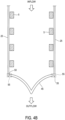
- inflow end 10 of tubular body 5 includes struts 9 with peaks 70 and valleys 75. Peaks 70 are disposed proximally of valleys 75 such that valleys 75 are located closer to outflow end 15 of tubular body 5 than peaks 70. Furthermore, peaks 70 and valleys 75 may form proximal-most end 13 of tubular body 5.
- peaks 70 and valleys 75 may be configured such that movement of peaks 70 radially inward may cause valleys 75 to flare radially outward ( Figure 8 ).
- the patient's atrial wall may push radially inward on peaks 70 (due to normal systolic movement of the patient's native valve). This causes peaks 70 to deform and move radially inward, as shown in Figure 8 .
- the inward movement by peaks 70 causes valleys 75 to deform and move radially outward.
- the deformation of valleys 75 radially outward pushes inflow end 10 further into contact with the patient's atrial wall, thus improving the sealing effect of inflow end 10 within the patient.
- outflow end 15 of tubular body 5 may include beams 60 and a proximal section 80. Both beams 60 and proximal section 80 may be disposed distal, in an outflow direction, of preformed groove 7. Proximal section 80 may also be disposed distally of peaks 70 and valleys 75 in an outflow direction. Furthermore, beams 60 may be disposed distal, in an outflow direction, of proximal section 80. Accordingly, as shown in Figure 10 , movement of proximal section 80 radially inward may cause inflow end 10 of tubular body 5 to flare radially outward. For example, natural movement of a patient's native valve may cause an inward compression on tubular body 5.
- the patient's native valve may cause an inward compression on valve leaflets 45, which in turn may cause an inward compression on tubular body 5.
- a compression may cause proximal section 80 to be compressed radially inward.
- movement of proximal section 80 radially inward causes inflow end 10 to flare radially outward.
- the outward movement of inflow end 10 may increase the sealing effect between inflow end 10 and a patient's atrial wall, thus advantageously providing a tighter seal between tubular body 5 and the patient's atrial wall.
- beams 60 may not move.
- connection points 65 may dissociate such movement of proximal section 80 from beams 60.
- connection points 65 may be disposed in proximal section 80.
- connection points 65 may be disposed distal of proximal section 80 in an outflow direction.
- valve leaflets 45 may extend entirely distal of proximal section 80 in an outflow direction. In other embodiments, valve leaflets 45 may axially overlap with proximal section 80.
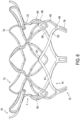
- Figure 11 shows an additional configuration of struts 9 in which inflow end 10 of tubular body 5 includes struts 9 with an S-shape.
- the S-shaped struts may be directly connected to peaks 70 such that both peaks 70 and valleys 75 are disposed above the S-shaped struts in an inflow direction, when tubular body 5 is in an expanded state.
- the S-shaped struts may each form a decorrelation portion that dissociates movements between proximal-most end 13 of tubular body 6 and outflow end 15 of tubular body 5.
- the S-shaped struts may be configured to stress and compress in reaction to movement in inflow end 10 or outflow end 15.
- the S-shaped struts stretch and/or compress, movement from one end of the tubular body 5 does not translate/communicate to the other end of the tubular body 5.
- the S-shaped struts may be disposed entirely proximal of preformed groove 7 in an inflow direction.
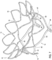
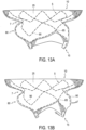
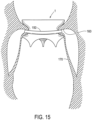
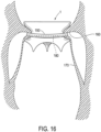
- tubular body 5 may include a motion buffer component 90 integrated in tubular body 5 ( Figures 11-13B ).
- Motion buffer component 90 may include one or more struts 9 formed into, for example, a droplet shape ( Figure 11 ) or a triangular shape ( Figure 12 ).
- Motion buffer component 90 may be integral with the remainder of tubular body 5 such that tubular body 5 forms one unitary member.
- fabric 25 may be disposed over an outer surface of motion buffer component 90.
- valve leaflets 45 may move inward and outward when replacing the functions of the native valve within a patient. Such movement may cause, for example, outflow end 15 of tubular body 5 to be pushed radially inward and outward with regard to the patient's atrial wall. Such movement of outflow end 15 also causes fabric 25 to be pushed radially inward and outward with regard to the patient's atrial wall. This movement of fabric 25 against the patient's native valve may cause friction and wear on fabric 25. Furthermore, tubular body 5 may also suffer from friction and wear by continued contact with the patient's native valve.
- Motion buffer component 90 may create a bumper effect to reduce such friction and wear on fabric 25 and tubular body 5.
- motion buffer component 90 may be configured to not move radially inward with outflow end 15. Instead, motion buffer component 90 may move radially outward or may stay in its position in reaction to the inward movement of outflow end 15.
- motion buffer component 90 may push radially outward, against fabric 25 and against the patient's native valve leaflets, when outflow end 15 moves radially inward.
- Such radially outward pushing by motion buffer component 90 may create the bumper effect.
- motion buffer component 90 when outflow end 15 and fabric 25 are pushed from the radially inward position to the radially outward position (due to movement of valve leaflets 45), because motion buffer component 90 already protrudes outward, motion buffer component 90 provides a cushioning effect to soften the radially outward force of outflow end 15 and fabric 25 on the patient's native valve leaflets.
- motion buffer component 90 may absorb friction and wear on tubular body 5 that are caused from movement of valve leaflets 45.
- motion buffer component 90 may advantageously make tubular body 5, especially beams 60, more durable.
- motion buffer component 90 may absorb friction and wear on fabric 25 that are caused from movement of valve leaflets 45.
- motion buffer component 90 may also advantageously make fabric 25 more durable.
- Figure 13A shows a neutral state of tubular body 5
- Figure 13B shows a state of tubular body 5 in which outflow end 15 is moved radially inward and motion buffer component 90 is moved radially outward.
- the structure and/or location of motion buffer component 90 may enable motion buffer component 90 to move radially outward or to stay in its position in response to the inward movement by outflow end 15.
- motion buffer component 90 may be disposed adjacent to beams 60 and distal of preformed groove 7 in an outflow direction.
- Motion buffer component 90 may be disposed within proximal section 80.
- a strut width of motion buffer component 90 may be smaller than a strut width of beams 60.
- motion buffer component 90 may have sufficient flexibility to move radially outward or to stay in its position, as discussed above.
- motion buffer component 90 may be located at the same cross-section as valve leaflets 45 in a radial direction. Thus, motion buffer component 90 and valve leaflets 45 may overlap axially along longitudinal axis 20. According to the invention, motion buffer component 90 is located at least in part at the same cross-section as connection points 65 in a radial direction. Thus, motion buffer component 90 and connection points 65 may overlap axially along longitudinal axis 20.
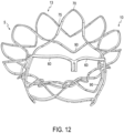
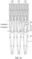
- Figure 14 shows an embodiment in which tubular body 5 includes struts 9 with different thicknesses.
- struts 9 may include relatively smaller thicknesses 100 and relatively larger thicknesses 110.
- struts 9 may be curved in order to form first cells 120 and second cells 130.
- first cells 120 are formed by the struts with relatively smaller thicknesses 100
- second cells 130 are formed by the struts with the relatively larger thicknesses 110.
- third cells 140 may be disposed between first cells 120 and second cells 130.
- Third cells may be formed by both the struts with the relatively smaller thicknesses 100 and the struts with the relatively larger thicknesses 110.
- First cells 120, second cells 130, and third cells 140 may be configured to open and expand uniformly when tubular body 5 is opened and expanded.
- the struts with relatively smaller and larger thicknesses 100, 110 allow all cells 120, 130, 140 to open together at the same rate.
- some strut cells may require less outward force to open, depending on their placement in the mesh structure of the prosthesis device. Therefore, some struts cells may open easier and quicker than other strut cells. Such results in the prosthesis being expanded and opened non-uniformly. For example, the strut cells that open easier may fully open before the strut cells that are harder to open.
- valve prosthesis 1 expands uniformly during manufacturing (e.g., during its heat shaping process). Accordingly, cells 120, 130, 140 provide a prosthesis device that is easier to manufacture compared to traditional prosthesis devices.
- the struts with the relatively larger thicknesses 110 may be placed at locations on tubular body 5 that open relatively easier.
- the struts with the relatively smaller thicknesses 100 may be placed at locations on tubular body 5 that open with relatively more difficultly.
- the thickness of the struts may counter balance with the ease of opening in order to provide uniform expansion across all cells of tubular body 5.
- valve prosthesis 1 may include positioning and/or orientation devices (not shown) to facilitate relative and/or absolute positioning of tubular body 5.
- These devices may include passive markers that are fixedly attached to tubular body 5.
- the passive markers may be made from materials different from the materials of tubular body 5 in order to improve contrast during medical imaging, e.g., using magnetic resonance or X-ray based imaging techniques.
- the passive markers may, for example, be made of highly radio-opaque materials thereby allowing one to precisely acquire the relative and/or absolute position of the components of valve prosthesis 1 with respect to the patient's body.
- valve prosthesis 1 may allow for a smaller outer profile than conventional prosthesis.
- valve prosthesis 1 may be sized according to human anatomies and may be compressed into a 26F ID tubing catheter for delivery within a patient.
- valve leaflets 45 extend distally beyond tubular body 5, the size of the frame of tubular body 5 required to support valve 40 may be reduced.
- the number of struts 9 may be reduced, thus providing a more flexible structure.
- the configuration of valve prosthesis 1 provides a better geometrical stability for valve leaflets 45 compared to conventional prosthesis.
- valve prosthesis 1 may be deployed, via a catheter, to a patient.
- the method of delivering valve prosthesis 1 may include delivering, from a delivery catheter, tubular body 5 and valve 40.
- tubular body 5 and valve 40 may be expanded such that beams 60 of tubular 5 are disposed against tissue of a patient's connection channel between an atrial and a ventricular chamber of a heart.
- valve prosthesis 1 may be delivered to a patient's defective mitral or tricuspid valve in order to restore operability.
- Valve prosthesis 1 may be delivered to a patient so that the preformed groove 7 is located on the ventricular side of the annulus of the native valve (e.g., having a distance from the native valve annulus).
- valve prosthesis 1 within the patient's heart valve, the following approaches may be applied: (1) an arterial retrograde approach entering the heart cavity over the aorta, (2) through a venous access and through a puncture through the inter atrial septum (trans-septal approach), (3) over a puncture through the apex of the heart (trans- apical approach), (4) over a puncture through the atrial wall from outside the heart, (5) arterial access (e.g., from the femoral artery through a puncture in the groin), (6) directly through the vena cava and into the right atrium (for a tricuspid valve replacement, for example), or (7) any other approach known to a skilled person.
- arterial access e.g., from the femoral artery through a puncture in the groin
- (6) directly through the vena cava and into the right atrium for a tricuspid valve replacement, for example
- any other approach known to a skilled person may be applied: (1) an
- valve prosthesis 1 may be fixed relative to the patient's connection channel wall structure such that an exterior of valve prosthesis 1 is sealed against blood flow.
- tissue of the patient's connection channel wall structure adjacent to the preformed groove 7 may be forced or placed inside preformed groove 7.
- the method may further include advancing a trapping member 150 around tubular body 5 and around preformed groove 7.
- trapping member 150 may trap portions of native valve leaflets 160 and/or chords 170 in preformed groove 7. Such may help secure tubular body 5 in a patient.
- Trapping member 150 may include a full or partial loop. Additionally, trapping member 150 may be moved around tubular body 5 after tubular body 5 is fully expanded or when tubular body 5 is only partially expanded. Trapping member 150 may be loosely disposed within preformed groove such that an interference fit between trapping member 150 and preformed groove 7 secures tubular body 5 in place. Thus, trapping member 150 may serve to anchor valve prosthesis 1 within the patient.
- trapping member 150 may exert an inward, radial force on tubular body 5 in order to anchor valve prosthesis 1 within the patient.
- trapping member 150 may exert a frictional force on the native valve leaflets 160 and/or chords 170.
- Trapping member 150 may include a delivery configuration within a delivery catheter and a deployment configuration wherein trapping member 150 is deployed from the delivery catheter. In embodiments, trapping member 150 may be biased to the deployment configuration.
- trapping member 150 may include a shape-memory alloy such as a Nitinol or a Nitinol-based alloy.
- an elongate outer member 180 may also be advanced around tubular body 5 and around preformed groove 7.
- Elongate outer member 180 may encircle tubular body 5 after tubular body 5 is fully expanded or when tubular body 5 is only partially expanded.
- Elongate outer member 180 may force the patient's native valve leaflets 160 and/or chords 170 in preformed groove 7.
- Trapping member 150 may then be disposed over and along elongate outer member 180 in order to advance trapping member 150 around tubular body 5 and into preformed groove 7.
- Elongate outer member 180 may then be removed from the patient after trapping member 150 is disposed around tubular body 5. After elongate outer member 180 is removed from the patient, trapping member 150 may maintain the patient's native valve leaflets 160 and/or chords 170 in preformed groove 7.
- elongate outer member 180 may be a guidewire. Elongate outer member 180 may have a diameter smaller than a diameter of trapping member 150.
- valve prosthesis 1 may result in fixation of tubular body 5 in the patient's connection channel wall structure with minimal occlusion of the patient's native valve.
- the disclosed embodiments also include a method for manufacturing valve prosthesis 1.
- the method for manufacturing may include directly connecting outer circumferential edge 50 of valve 40 with outflow end 35 of fabric 25 to form a sub-assembly.
- tubular body 5 may be slid into the sub-assembly.
- tubular body 5 may be connected to the sub-assembly to form an assembly such that valve leaflets 45 extend distally of outflow end 15 of tubular body 5 in an outflow direction.
- Tubular body 5 may be directly connected to the sub-assembly by connecting outflow end 15 of tubular body 5 with fabric 25.
- fabric 25 may be directly connected to outer circumferential edge 50 and directly connected to tubular body 5 with one or more sutures 55.
Landscapes
- Health & Medical Sciences (AREA)
- Engineering & Computer Science (AREA)
- Biomedical Technology (AREA)
- Cardiology (AREA)
- Oral & Maxillofacial Surgery (AREA)
- Transplantation (AREA)
- Heart & Thoracic Surgery (AREA)
- Vascular Medicine (AREA)
- Life Sciences & Earth Sciences (AREA)
- Animal Behavior & Ethology (AREA)
- General Health & Medical Sciences (AREA)
- Public Health (AREA)
- Veterinary Medicine (AREA)
- Manufacturing & Machinery (AREA)
- Prostheses (AREA)
Claims (8)
- Herzklappensystem (1), wobei das System aufweist:einen radial selbstexpandierbaren rohrförmigen Körper (5) mit einem Einström-Ende (10) und einem Ausström-Ende (15), wobei der rohrförmige Körper (5) eine Mehrzahl von Streben (9, 12) mit mindestens einer in den rohrförmigen Körper integrierten Bewegungspufferkomponente (90) aufweist,ein Ventil (40), das mit dem rohrförmigen Körper (5) verbunden ist, wobei das Ventil (40) eine Mehrzahl von Ventilsegeln (45) aufweist, undein Gewebe (25), das über einer Außenfläche des rohrförmigen Körpers (5) und über einer Außenfläche der Bewegungspufferkomponente (90) angeordnet ist,wobei, wenn sich das Ausström-Ende (15) des rohrförmigen Körpers (5) von einer Bewegung der Ventilsegel (45) radial nach innen bewegt, die Bewegungspufferkomponente (90) konfiguriert ist, um sich nicht mit dem Ausström-Ende (15) des rohrförmigen Körpers (5) radial nach innen zu bewegen, dadurch gekennzeichnet, dass sich die mindestens eine Bewegungspufferkomponente (90) von einer Einström-Ende-Seite davon, die mit dem rohrförmigen Körper (5) verbunden ist, zu einer Freies-Ausström-Ende-Seite davon erstreckt, die nicht mit dem rohrförmigen Körper (5) verbunden ist,wobei:der rohrförmige Körper (5) eine Mehrzahl von Trägern (60) am Ausström-Ende (15) des rohrförmigen Körpers (5) aufweist, wobei die Mehrzahl von Trägern (60) Verbindungspunkte (65) zwischen dem Einström-Ende (10) und der Mehrzahl von Trägern (60) bereitstellt, wobei eine Anzahl von Verbindungspunkten (65) einer Anzahl der Ventilsegel (45) entspricht, unddie Bewegungspufferkomponente (90) zumindest teilweise am gleichen Querschnitt wie die Verbindungspunkte (65) in einer radialen Richtung angeordnet ist.
- System (1) gemäß Anspruch 1, wobei die Bewegungspufferkomponente (90) konfiguriert ist, um sich radial nach außen zu bewegen, wenn sich das Ausström-Ende (15) des rohrförmigen Körpers (5) radial nach innen bewegt.
- System (1) gemäß Anspruch 2, wobei die Bewegungspufferkomponente (90) konfiguriert ist, um radial nach außen gegen das Gewebe (25) zu drücken, wenn sich das Ausström-Ende (15) des rohrförmigen Körpers (5) radial nach innen bewegt.
- System (1) gemäß Anspruch 1, wobei die Bewegungspufferkomponente (90) eine Tröpfchenform oder eine Dreiecksform hat.
- System (1) gemäß Anspruch 1, ferner aufweisend ein Einfangelement (150), das konfiguriert ist, um zumindest eine teilweise Schleife auszubilden, die den rohrförmigen Körper (5) umgibt, um Abschnitte von nativen Ventilsegeln (160) und/oder Sehnen (170) einzufangen.
- System (1) gemäß Anspruch 5, ferner aufweisend ein langgestrecktes äußeres Element (180), das konfiguriert ist, um den rohrförmigen Körper (5) zu umgeben, so dass das Einfangelement (150) über und entlang des langgestreckten äußeren Elements (180) angeordnet ist.
- System (1) gemäß Anspruch 1, wobei eine Strebenbreite der Bewegungspufferkomponente (90) kleiner als eine Strebenbreite der Träger (60) ist.
- System (1) gemäß Anspruch 1, wobei die Bewegungspufferkomponente (90) am gleichen Querschnitt wie die Ventilsegel (45) in einer radialen Richtung angeordnet ist.
Applications Claiming Priority (2)
| Application Number | Priority Date | Filing Date | Title |
|---|---|---|---|
| US15/343,359 US9999502B2 (en) | 2016-11-04 | 2016-11-04 | Transcather valve prosthesis |
| PCT/IB2017/001554 WO2018083540A1 (en) | 2016-11-04 | 2017-11-06 | Transcatheter valve prosthesis |
Publications (3)
| Publication Number | Publication Date |
|---|---|
| EP3534840A1 EP3534840A1 (de) | 2019-09-11 |
| EP3534840B1 EP3534840B1 (de) | 2022-01-05 |
| EP3534840B2 true EP3534840B2 (de) | 2025-02-19 |
Family
ID=60972252
Family Applications (1)
| Application Number | Title | Priority Date | Filing Date |
|---|---|---|---|
| EP17829277.7A Active EP3534840B2 (de) | 2016-11-04 | 2017-11-06 | Transkatheter-klappenprothese |
Country Status (7)
| Country | Link |
|---|---|
| US (1) | US9999502B2 (de) |
| EP (1) | EP3534840B2 (de) |
| JP (1) | JP7038711B2 (de) |
| CN (1) | CN110035712B (de) |
| AU (1) | AU2017353941B2 (de) |
| CA (1) | CA3042938A1 (de) |
| WO (1) | WO2018083540A1 (de) |
Families Citing this family (28)
| Publication number | Priority date | Publication date | Assignee | Title |
|---|---|---|---|---|
| US8579964B2 (en) | 2010-05-05 | 2013-11-12 | Neovasc Inc. | Transcatheter mitral valve prosthesis |
| US9308087B2 (en) | 2011-04-28 | 2016-04-12 | Neovasc Tiara Inc. | Sequentially deployed transcatheter mitral valve prosthesis |
| US9554897B2 (en) | 2011-04-28 | 2017-01-31 | Neovasc Tiara Inc. | Methods and apparatus for engaging a valve prosthesis with tissue |
| US9345573B2 (en) | 2012-05-30 | 2016-05-24 | Neovasc Tiara Inc. | Methods and apparatus for loading a prosthesis onto a delivery system |
| US9572665B2 (en) | 2013-04-04 | 2017-02-21 | Neovasc Tiara Inc. | Methods and apparatus for delivering a prosthetic valve to a beating heart |
| CN113069242A (zh) | 2015-12-15 | 2021-07-06 | 内奥瓦斯克迪亚拉公司 | 经中隔递送系统 |
| JP7006940B2 (ja) | 2016-01-29 | 2022-01-24 | ニオバスク ティアラ インコーポレイテッド | 流出の閉塞を回避するための人工弁 |
| US10188514B2 (en) * | 2016-11-04 | 2019-01-29 | Highlife Sas | Transcatheter valve prosthesis |
| US20180140419A1 (en) | 2016-11-21 | 2018-05-24 | Neovasc Tiara Inc. | Methods and systems for rapid retraction of a transcatheter heart valve delivery system |
| CA3073834A1 (en) | 2017-08-25 | 2019-02-28 | Neovasc Tiara Inc. | Sequentially deployed transcatheter mitral valve prosthesis |
| CA3279869A1 (en) | 2018-08-21 | 2025-11-29 | Shifamed Holdings Llc | Prosthetic cardiac valve devices, systems, and methods |
| JP7528068B2 (ja) | 2018-10-05 | 2024-08-05 | シファメド・ホールディングス・エルエルシー | 人工心弁デバイス、システム、および方法 |
| EP3866900B1 (de) | 2018-10-19 | 2026-01-28 | Shifamed Holdings, LLC | Einstellbare medizinische vorrichtung |
| EP3876870B1 (de) | 2018-11-08 | 2023-12-20 | Neovasc Tiara Inc. | Ventrikuläres einsetzen einer transkathetermitralklappenprothese |
| AU2020233892A1 (en) | 2019-03-08 | 2021-11-04 | Neovasc Tiara Inc. | Retrievable prosthesis delivery system |
| WO2020188552A1 (en) * | 2019-03-21 | 2020-09-24 | Vong Medical Ltd | Artificial heart valve and methods for implanting the same |
| AU2020256195B2 (en) | 2019-04-01 | 2022-10-13 | Neovasc Tiara Inc. | Controllably deployable prosthetic valve |
| CN113924065B (zh) | 2019-04-10 | 2026-01-30 | 内奥瓦斯克迪亚拉公司 | 具有自然血流的假体瓣膜 |
| US11779742B2 (en) | 2019-05-20 | 2023-10-10 | Neovasc Tiara Inc. | Introducer with hemostasis mechanism |
| US11311376B2 (en) | 2019-06-20 | 2022-04-26 | Neovase Tiara Inc. | Low profile prosthetic mitral valve |
| US20230105492A1 (en) * | 2020-03-03 | 2023-04-06 | Shifamed Holdings, Llc | Prosthetic cardiac valve devices, systems, and methods |
| EP4149393A4 (de) * | 2020-05-15 | 2023-11-01 | Revalve Solutions Inc. | Vorrichtungen, systeme und verfahren für eine zusammenklappbare und expandierbare herzklappenersatz |
| JP2023538957A (ja) * | 2020-08-31 | 2023-09-12 | シファメド・ホールディングス・エルエルシー | 張り出し人工心弁送達デバイスおよびシステム |
| JP2023543757A (ja) | 2020-09-23 | 2023-10-18 | リバルブ ソリューションズ インコーポレイテッド | 植え込み式心臓弁アダプタのための装置、システム、及び方法 |
| CN112155788B (zh) * | 2020-10-15 | 2023-09-08 | 上海臻亿医疗科技有限公司 | 一种植入式假体瓣膜装置 |
| US12329635B2 (en) * | 2020-12-04 | 2025-06-17 | Shifamed Holdings, Llc | Flared prosthetic cardiac valve delivery devices and systems |
| DE102021000811A1 (de) * | 2021-02-10 | 2022-08-11 | Devie Medical Gmbh | Wirkstofffreisetzende Herzklappenprothese, welche infizierte Gewebestrukturen im Herzen kompartimentiert oder einer postoperativen Infektion vorbeugt |
| EP4522075A1 (de) * | 2022-05-13 | 2025-03-19 | St. Jude Medical, Cardiology Division, Inc. | Transkatheterklappe - einzelstentstruktur mit gewebe |
Citations (17)
| Publication number | Priority date | Publication date | Assignee | Title |
|---|---|---|---|---|
| US20060004442A1 (en) † | 2004-06-30 | 2006-01-05 | Benjamin Spenser | Paravalvular leak detection, sealing, and prevention |
| WO2006113906A1 (en) † | 2005-04-20 | 2006-10-26 | The Cleveland Clinic Foundation | Apparatus and method for replacing a cardiac valve |
| US20090157175A1 (en) † | 2007-12-14 | 2009-06-18 | Edwards Lifesciences Corporation | Leaflet attachment frame for a prosthetic valve |
| US20090216312A1 (en) † | 2008-02-26 | 2009-08-27 | Helmut Straubinger | Stent for the Positioning and Anchoring of a Valvular Prosthesis in an Implantation Site in the Heart of a Patient |
| WO2011057087A1 (en) † | 2009-11-05 | 2011-05-12 | The Trustees University Of Pennsylvania | Valve prosthesis |
| US20120053682A1 (en) † | 2010-09-01 | 2012-03-01 | Medtronic Vascular Galway Limited | Prosthetic Valve Support Structure |
| US20120078357A1 (en) † | 2010-09-27 | 2012-03-29 | Edwards Lifesciences Corporation | Prosthetic Heart Valve Frame With Flexible Commissures |
| US20120271398A1 (en) † | 2009-11-02 | 2012-10-25 | Symetis Sa | Aortic bioprosthesis and systems for delivery thereof |
| WO2014028112A1 (en) † | 2012-08-13 | 2014-02-20 | Medtronic Inc. | Heart valve prosthesis |
| WO2014121275A1 (en) † | 2013-02-04 | 2014-08-07 | Edwards Lifesciences Corporation | Prosthetic valve for replacing mitral valve |
| EP2777616A1 (de) † | 2013-03-14 | 2014-09-17 | CardiAQ Valve Technologies, Inc. | Prothese zum nicht traumatischen Ergreifen von intraluminalem Gewebe |
| WO2014164151A1 (en) † | 2013-03-12 | 2014-10-09 | Medtronic Inc. | Heart valve prosthesis |
| US20150230923A1 (en) † | 2014-02-18 | 2015-08-20 | Edwards Lifesciences Corporation | Flexible commissure frame |
| WO2018083543A1 (en) † | 2016-11-04 | 2018-05-11 | Highlife Sas | Transcatheter valve prosthesis |
| WO2018083542A2 (en) † | 2016-11-04 | 2018-05-11 | Highlife Sas | Transcatheter valve prosthesis |
| WO2018083541A1 (en) † | 2016-11-04 | 2018-05-11 | Highlife Sas | Transcatheter valve prosthesis |
| WO2018083544A1 (en) † | 2016-11-04 | 2018-05-11 | Highlife Sas | Transcatheter valve prosthesis |
Family Cites Families (40)
| Publication number | Priority date | Publication date | Assignee | Title |
|---|---|---|---|---|
| WO1999015108A2 (en) | 1997-09-24 | 1999-04-01 | Med Institute, Inc. | Radially expandable stent |
| US6395019B2 (en) | 1998-02-09 | 2002-05-28 | Trivascular, Inc. | Endovascular graft |
| US6139575A (en) | 1999-04-02 | 2000-10-31 | Medtronic, Inc. | Hybrid mechanical heart valve prosthesis |
| US6325825B1 (en) | 1999-04-08 | 2001-12-04 | Cordis Corporation | Stent with variable wall thickness |
| US6458153B1 (en) | 1999-12-31 | 2002-10-01 | Abps Venture One, Ltd. | Endoluminal cardiac and venous valve prostheses and methods of manufacture and delivery thereof |
| US6454799B1 (en) | 2000-04-06 | 2002-09-24 | Edwards Lifesciences Corporation | Minimally-invasive heart valves and methods of use |
| US8007528B2 (en) | 2004-03-17 | 2011-08-30 | Boston Scientific Scimed, Inc. | Bifurcated stent |
| DE102005052628B4 (de) | 2005-11-04 | 2014-06-05 | Jenavalve Technology Inc. | Selbstexpandierendes, flexibles Drahtgeflecht mit integrierter Klappenprothese für den transvaskulären Herzklappenersatz und ein System mit einer solchen Vorrichtung und einem Einführkatheter |
| US20080275550A1 (en) | 2006-02-24 | 2008-11-06 | Arash Kheradvar | Implantable small percutaneous valve and methods of delivery |
| WO2008150529A1 (en) * | 2007-06-04 | 2008-12-11 | St. Jude Medical, Inc. | Prosthetic heart valves |
| ES2384199T3 (es) | 2007-08-24 | 2012-07-02 | St. Jude Medical, Inc. | Válvulas cardiacas aórticas protésicas |
| AU2008305600B2 (en) * | 2007-09-26 | 2013-07-04 | St. Jude Medical, Inc. | Collapsible prosthetic heart valves |
| EP2679198B1 (de) | 2007-10-25 | 2021-03-24 | Symetis SA | Stents mit Klappen und Systeme für zur deren Einführung |
| CA2749026C (en) | 2008-09-29 | 2018-01-09 | Impala, Inc. | Heart valve |
| US20100217382A1 (en) | 2009-02-25 | 2010-08-26 | Edwards Lifesciences | Mitral valve replacement with atrial anchoring |
| AU2010218384B2 (en) | 2009-02-27 | 2014-11-20 | St. Jude Medical, Inc. | Stent features for collapsible prosthetic heart valves |
| WO2010141847A1 (en) | 2009-06-05 | 2010-12-09 | Ats Medical, Inc. | Flexible commissure structure for attaching valve bioprosthesis |
| US9072603B2 (en) | 2010-02-24 | 2015-07-07 | Medtronic Ventor Technologies, Ltd. | Mitral prosthesis and methods for implantation |
| US9522062B2 (en) | 2010-02-24 | 2016-12-20 | Medtronic Ventor Technologies, Ltd. | Mitral prosthesis and methods for implantation |
| SE535690C2 (sv) * | 2010-03-25 | 2012-11-13 | Jan Otto Solem | En implanterbar anordning och kit för hjärtunderstöd, innefattande medel för generering av longitudinell rörelse av mitralisklaffen |
| JP2013526388A (ja) * | 2010-05-25 | 2013-06-24 | イエナバルブ テクノロジー インク | 人工心臓弁、及び人工心臓弁とステントを備える経カテーテル搬送体内プロテーゼ |
| HUE056970T2 (hu) | 2010-10-05 | 2022-04-28 | Edwards Lifesciences Corp | Szívbillentyû-protézis és bevezetõ készülék |
| CN107496054B (zh) | 2011-06-21 | 2020-03-03 | 托尔福公司 | 人工心脏瓣膜装置及相关系统和方法 |
| US9216076B2 (en) | 2011-09-09 | 2015-12-22 | Endoluminal Sciences Pty. Ltd. | Means for controlled sealing of endovascular devices |
| WO2013059747A1 (en) * | 2011-10-19 | 2013-04-25 | Foundry Newco Xii, Inc. | Prosthetic heart valve devices, prosthetic mitral valves and associated systems and methods |
| US20140350669A1 (en) | 2011-12-01 | 2014-11-27 | The Trustees if The University of Pennsylvania | Percutaneous valve replacement devices |
| US20150094802A1 (en) | 2012-02-28 | 2015-04-02 | Mvalve Technologies Ltd. | Single-ring cardiac valve support |
| US10206775B2 (en) * | 2012-08-13 | 2019-02-19 | Medtronic, Inc. | Heart valve prosthesis |
| US9066801B2 (en) | 2013-01-08 | 2015-06-30 | Medtronic, Inc. | Valve prosthesis and method for delivery |
| US20140277427A1 (en) | 2013-03-14 | 2014-09-18 | Cardiaq Valve Technologies, Inc. | Prosthesis for atraumatically grasping intralumenal tissue and methods of delivery |
| GB2513195A (en) | 2013-04-19 | 2014-10-22 | Strait Access Tech Holdings Pty Ltd | A stent for a prosthetic heart valve |
| US20160106539A1 (en) | 2013-05-29 | 2016-04-21 | Mvalve Technologies Ltd. | Cardiac valve support device fitted with valve leaflets |
| US20150005874A1 (en) | 2013-06-27 | 2015-01-01 | Tendyne Holdings, Inc. | Atrial Thrombogenic Sealing Pockets for Prosthetic Mitral Valves |
| US9901444B2 (en) | 2013-12-17 | 2018-02-27 | Edwards Lifesciences Corporation | Inverted valve structure |
| CA2940363C (en) | 2014-02-28 | 2023-08-15 | Highlife Sas | Transcatheter valve prosthesis |
| US10064719B2 (en) | 2014-03-11 | 2018-09-04 | Highlife Sas | Transcatheter valve prosthesis |
| US9889003B2 (en) * | 2014-03-11 | 2018-02-13 | Highlife Sas | Transcatheter valve prosthesis |
| US9763779B2 (en) | 2014-03-11 | 2017-09-19 | Highlife Sas | Transcatheter valve prosthesis |
| US9687343B2 (en) * | 2014-03-11 | 2017-06-27 | Highlife Sas | Transcatheter valve prosthesis |
| CA3161000A1 (en) | 2014-05-19 | 2015-11-26 | Edwards Lifesciences Cardiaq Llc | Replacement mitral valve with annular flap |
-
2016
- 2016-11-04 US US15/343,359 patent/US9999502B2/en active Active
-
2017
- 2017-11-06 JP JP2019523570A patent/JP7038711B2/ja active Active
- 2017-11-06 CA CA3042938A patent/CA3042938A1/en active Pending
- 2017-11-06 EP EP17829277.7A patent/EP3534840B2/de active Active
- 2017-11-06 WO PCT/IB2017/001554 patent/WO2018083540A1/en not_active Ceased
- 2017-11-06 CN CN201780075178.4A patent/CN110035712B/zh active Active
- 2017-11-06 AU AU2017353941A patent/AU2017353941B2/en active Active
Patent Citations (17)
| Publication number | Priority date | Publication date | Assignee | Title |
|---|---|---|---|---|
| US20060004442A1 (en) † | 2004-06-30 | 2006-01-05 | Benjamin Spenser | Paravalvular leak detection, sealing, and prevention |
| WO2006113906A1 (en) † | 2005-04-20 | 2006-10-26 | The Cleveland Clinic Foundation | Apparatus and method for replacing a cardiac valve |
| US20090157175A1 (en) † | 2007-12-14 | 2009-06-18 | Edwards Lifesciences Corporation | Leaflet attachment frame for a prosthetic valve |
| US20090216312A1 (en) † | 2008-02-26 | 2009-08-27 | Helmut Straubinger | Stent for the Positioning and Anchoring of a Valvular Prosthesis in an Implantation Site in the Heart of a Patient |
| US20120271398A1 (en) † | 2009-11-02 | 2012-10-25 | Symetis Sa | Aortic bioprosthesis and systems for delivery thereof |
| WO2011057087A1 (en) † | 2009-11-05 | 2011-05-12 | The Trustees University Of Pennsylvania | Valve prosthesis |
| US20120053682A1 (en) † | 2010-09-01 | 2012-03-01 | Medtronic Vascular Galway Limited | Prosthetic Valve Support Structure |
| US20120078357A1 (en) † | 2010-09-27 | 2012-03-29 | Edwards Lifesciences Corporation | Prosthetic Heart Valve Frame With Flexible Commissures |
| WO2014028112A1 (en) † | 2012-08-13 | 2014-02-20 | Medtronic Inc. | Heart valve prosthesis |
| WO2014121275A1 (en) † | 2013-02-04 | 2014-08-07 | Edwards Lifesciences Corporation | Prosthetic valve for replacing mitral valve |
| WO2014164151A1 (en) † | 2013-03-12 | 2014-10-09 | Medtronic Inc. | Heart valve prosthesis |
| EP2777616A1 (de) † | 2013-03-14 | 2014-09-17 | CardiAQ Valve Technologies, Inc. | Prothese zum nicht traumatischen Ergreifen von intraluminalem Gewebe |
| US20150230923A1 (en) † | 2014-02-18 | 2015-08-20 | Edwards Lifesciences Corporation | Flexible commissure frame |
| WO2018083543A1 (en) † | 2016-11-04 | 2018-05-11 | Highlife Sas | Transcatheter valve prosthesis |
| WO2018083542A2 (en) † | 2016-11-04 | 2018-05-11 | Highlife Sas | Transcatheter valve prosthesis |
| WO2018083541A1 (en) † | 2016-11-04 | 2018-05-11 | Highlife Sas | Transcatheter valve prosthesis |
| WO2018083544A1 (en) † | 2016-11-04 | 2018-05-11 | Highlife Sas | Transcatheter valve prosthesis |
Also Published As
| Publication number | Publication date |
|---|---|
| CN110035712A (zh) | 2019-07-19 |
| AU2017353941A1 (en) | 2019-05-23 |
| WO2018083540A1 (en) | 2018-05-11 |
| JP7038711B2 (ja) | 2022-03-18 |
| EP3534840A1 (de) | 2019-09-11 |
| US9999502B2 (en) | 2018-06-19 |
| US20180125648A1 (en) | 2018-05-10 |
| JP2019533531A (ja) | 2019-11-21 |
| EP3534840B1 (de) | 2022-01-05 |
| CA3042938A1 (en) | 2018-05-11 |
| CN110035712B (zh) | 2021-05-11 |
| AU2017353941B2 (en) | 2022-06-02 |
Similar Documents
| Publication | Publication Date | Title |
|---|---|---|
| EP3534840B2 (de) | Transkatheter-klappenprothese | |
| EP3534841B1 (de) | Transkatheter-klappenprothese | |
| US11141266B2 (en) | Transcatheter valve prosthesis | |
| EP3534844B1 (de) | Transkatheter-klappenprothese | |
| EP3534842B1 (de) | Transkatheter-klappenprothese | |
| CA3042844C (en) | Heart valve system and use thereof |
Legal Events
| Date | Code | Title | Description |
|---|---|---|---|
| STAA | Information on the status of an ep patent application or granted ep patent |
Free format text: STATUS: UNKNOWN |
|
| STAA | Information on the status of an ep patent application or granted ep patent |
Free format text: STATUS: THE INTERNATIONAL PUBLICATION HAS BEEN MADE |
|
| PUAI | Public reference made under article 153(3) epc to a published international application that has entered the european phase |
Free format text: ORIGINAL CODE: 0009012 |
|
| STAA | Information on the status of an ep patent application or granted ep patent |
Free format text: STATUS: REQUEST FOR EXAMINATION WAS MADE |
|
| 17P | Request for examination filed |
Effective date: 20190503 |
|
| AK | Designated contracting states |
Kind code of ref document: A1 Designated state(s): AL AT BE BG CH CY CZ DE DK EE ES FI FR GB GR HR HU IE IS IT LI LT LU LV MC MK MT NL NO PL PT RO RS SE SI SK SM TR |
|
| AX | Request for extension of the european patent |
Extension state: BA ME |
|
| DAV | Request for validation of the european patent (deleted) | ||
| DAX | Request for extension of the european patent (deleted) | ||
| GRAP | Despatch of communication of intention to grant a patent |
Free format text: ORIGINAL CODE: EPIDOSNIGR1 |
|
| STAA | Information on the status of an ep patent application or granted ep patent |
Free format text: STATUS: GRANT OF PATENT IS INTENDED |
|
| INTG | Intention to grant announced |
Effective date: 20210608 |
|
| GRAS | Grant fee paid |
Free format text: ORIGINAL CODE: EPIDOSNIGR3 |
|
| GRAA | (expected) grant |
Free format text: ORIGINAL CODE: 0009210 |
|
| STAA | Information on the status of an ep patent application or granted ep patent |
Free format text: STATUS: THE PATENT HAS BEEN GRANTED |
|
| AK | Designated contracting states |
Kind code of ref document: B1 Designated state(s): AL AT BE BG CH CY CZ DE DK EE ES FI FR GB GR HR HU IE IS IT LI LT LU LV MC MK MT NL NO PL PT RO RS SE SI SK SM TR |
|
| REG | Reference to a national code |
Ref country code: GB Ref legal event code: FG4D |
|
| REG | Reference to a national code |
Ref country code: CH Ref legal event code: EP |
|
| REG | Reference to a national code |
Ref country code: AT Ref legal event code: REF Ref document number: 1459860 Country of ref document: AT Kind code of ref document: T Effective date: 20220115 |
|
| REG | Reference to a national code |
Ref country code: DE Ref legal event code: R096 Ref document number: 602017052000 Country of ref document: DE |
|
| REG | Reference to a national code |
Ref country code: IE Ref legal event code: FG4D |
|
| REG | Reference to a national code |
Ref country code: NL Ref legal event code: FP |
|
| REG | Reference to a national code |
Ref country code: LT Ref legal event code: MG9D |
|
| REG | Reference to a national code |
Ref country code: AT Ref legal event code: MK05 Ref document number: 1459860 Country of ref document: AT Kind code of ref document: T Effective date: 20220105 |
|
| PG25 | Lapsed in a contracting state [announced via postgrant information from national office to epo] |
Ref country code: SE Free format text: LAPSE BECAUSE OF FAILURE TO SUBMIT A TRANSLATION OF THE DESCRIPTION OR TO PAY THE FEE WITHIN THE PRESCRIBED TIME-LIMIT Effective date: 20220105 Ref country code: RS Free format text: LAPSE BECAUSE OF FAILURE TO SUBMIT A TRANSLATION OF THE DESCRIPTION OR TO PAY THE FEE WITHIN THE PRESCRIBED TIME-LIMIT Effective date: 20220105 Ref country code: PT Free format text: LAPSE BECAUSE OF FAILURE TO SUBMIT A TRANSLATION OF THE DESCRIPTION OR TO PAY THE FEE WITHIN THE PRESCRIBED TIME-LIMIT Effective date: 20220505 Ref country code: NO Free format text: LAPSE BECAUSE OF FAILURE TO SUBMIT A TRANSLATION OF THE DESCRIPTION OR TO PAY THE FEE WITHIN THE PRESCRIBED TIME-LIMIT Effective date: 20220405 Ref country code: LT Free format text: LAPSE BECAUSE OF FAILURE TO SUBMIT A TRANSLATION OF THE DESCRIPTION OR TO PAY THE FEE WITHIN THE PRESCRIBED TIME-LIMIT Effective date: 20220105 Ref country code: HR Free format text: LAPSE BECAUSE OF FAILURE TO SUBMIT A TRANSLATION OF THE DESCRIPTION OR TO PAY THE FEE WITHIN THE PRESCRIBED TIME-LIMIT Effective date: 20220105 Ref country code: ES Free format text: LAPSE BECAUSE OF FAILURE TO SUBMIT A TRANSLATION OF THE DESCRIPTION OR TO PAY THE FEE WITHIN THE PRESCRIBED TIME-LIMIT Effective date: 20220105 Ref country code: BG Free format text: LAPSE BECAUSE OF FAILURE TO SUBMIT A TRANSLATION OF THE DESCRIPTION OR TO PAY THE FEE WITHIN THE PRESCRIBED TIME-LIMIT Effective date: 20220405 |
|
| PG25 | Lapsed in a contracting state [announced via postgrant information from national office to epo] |
Ref country code: PL Free format text: LAPSE BECAUSE OF FAILURE TO SUBMIT A TRANSLATION OF THE DESCRIPTION OR TO PAY THE FEE WITHIN THE PRESCRIBED TIME-LIMIT Effective date: 20220105 Ref country code: LV Free format text: LAPSE BECAUSE OF FAILURE TO SUBMIT A TRANSLATION OF THE DESCRIPTION OR TO PAY THE FEE WITHIN THE PRESCRIBED TIME-LIMIT Effective date: 20220105 Ref country code: GR Free format text: LAPSE BECAUSE OF FAILURE TO SUBMIT A TRANSLATION OF THE DESCRIPTION OR TO PAY THE FEE WITHIN THE PRESCRIBED TIME-LIMIT Effective date: 20220406 Ref country code: FI Free format text: LAPSE BECAUSE OF FAILURE TO SUBMIT A TRANSLATION OF THE DESCRIPTION OR TO PAY THE FEE WITHIN THE PRESCRIBED TIME-LIMIT Effective date: 20220105 Ref country code: AT Free format text: LAPSE BECAUSE OF FAILURE TO SUBMIT A TRANSLATION OF THE DESCRIPTION OR TO PAY THE FEE WITHIN THE PRESCRIBED TIME-LIMIT Effective date: 20220105 |
|
| PG25 | Lapsed in a contracting state [announced via postgrant information from national office to epo] |
Ref country code: IS Free format text: LAPSE BECAUSE OF FAILURE TO SUBMIT A TRANSLATION OF THE DESCRIPTION OR TO PAY THE FEE WITHIN THE PRESCRIBED TIME-LIMIT Effective date: 20220505 |
|
| REG | Reference to a national code |
Ref country code: DE Ref legal event code: R026 Ref document number: 602017052000 Country of ref document: DE |
|
| PLBI | Opposition filed |
Free format text: ORIGINAL CODE: 0009260 |
|
| PLAX | Notice of opposition and request to file observation + time limit sent |
Free format text: ORIGINAL CODE: EPIDOSNOBS2 |
|
| PG25 | Lapsed in a contracting state [announced via postgrant information from national office to epo] |
Ref country code: SM Free format text: LAPSE BECAUSE OF FAILURE TO SUBMIT A TRANSLATION OF THE DESCRIPTION OR TO PAY THE FEE WITHIN THE PRESCRIBED TIME-LIMIT Effective date: 20220105 Ref country code: SK Free format text: LAPSE BECAUSE OF FAILURE TO SUBMIT A TRANSLATION OF THE DESCRIPTION OR TO PAY THE FEE WITHIN THE PRESCRIBED TIME-LIMIT Effective date: 20220105 Ref country code: RO Free format text: LAPSE BECAUSE OF FAILURE TO SUBMIT A TRANSLATION OF THE DESCRIPTION OR TO PAY THE FEE WITHIN THE PRESCRIBED TIME-LIMIT Effective date: 20220105 Ref country code: EE Free format text: LAPSE BECAUSE OF FAILURE TO SUBMIT A TRANSLATION OF THE DESCRIPTION OR TO PAY THE FEE WITHIN THE PRESCRIBED TIME-LIMIT Effective date: 20220105 Ref country code: DK Free format text: LAPSE BECAUSE OF FAILURE TO SUBMIT A TRANSLATION OF THE DESCRIPTION OR TO PAY THE FEE WITHIN THE PRESCRIBED TIME-LIMIT Effective date: 20220105 Ref country code: CZ Free format text: LAPSE BECAUSE OF FAILURE TO SUBMIT A TRANSLATION OF THE DESCRIPTION OR TO PAY THE FEE WITHIN THE PRESCRIBED TIME-LIMIT Effective date: 20220105 |
|
| 26 | Opposition filed |
Opponent name: NEOVASC TIARA INC. Effective date: 20221005 |
|
| PG25 | Lapsed in a contracting state [announced via postgrant information from national office to epo] |
Ref country code: AL Free format text: LAPSE BECAUSE OF FAILURE TO SUBMIT A TRANSLATION OF THE DESCRIPTION OR TO PAY THE FEE WITHIN THE PRESCRIBED TIME-LIMIT Effective date: 20220105 |
|
| PLBB | Reply of patent proprietor to notice(s) of opposition received |
Free format text: ORIGINAL CODE: EPIDOSNOBS3 |
|
| PG25 | Lapsed in a contracting state [announced via postgrant information from national office to epo] |
Ref country code: SI Free format text: LAPSE BECAUSE OF FAILURE TO SUBMIT A TRANSLATION OF THE DESCRIPTION OR TO PAY THE FEE WITHIN THE PRESCRIBED TIME-LIMIT Effective date: 20220105 |
|
| PG25 | Lapsed in a contracting state [announced via postgrant information from national office to epo] |
Ref country code: MC Free format text: LAPSE BECAUSE OF FAILURE TO SUBMIT A TRANSLATION OF THE DESCRIPTION OR TO PAY THE FEE WITHIN THE PRESCRIBED TIME-LIMIT Effective date: 20220105 |
|
| REG | Reference to a national code |
Ref country code: BE Ref legal event code: MM Effective date: 20221130 |
|
| PG25 | Lapsed in a contracting state [announced via postgrant information from national office to epo] |
Ref country code: LU Free format text: LAPSE BECAUSE OF NON-PAYMENT OF DUE FEES Effective date: 20221106 |
|
| PG25 | Lapsed in a contracting state [announced via postgrant information from national office to epo] |
Ref country code: BE Free format text: LAPSE BECAUSE OF NON-PAYMENT OF DUE FEES Effective date: 20221130 |
|
| PLAY | Examination report in opposition despatched + time limit |
Free format text: ORIGINAL CODE: EPIDOSNORE2 |
|
| PLBC | Reply to examination report in opposition received |
Free format text: ORIGINAL CODE: EPIDOSNORE3 |
|
| PG25 | Lapsed in a contracting state [announced via postgrant information from national office to epo] |
Ref country code: HU Free format text: LAPSE BECAUSE OF FAILURE TO SUBMIT A TRANSLATION OF THE DESCRIPTION OR TO PAY THE FEE WITHIN THE PRESCRIBED TIME-LIMIT; INVALID AB INITIO Effective date: 20171106 |
|
| PG25 | Lapsed in a contracting state [announced via postgrant information from national office to epo] |
Ref country code: CY Free format text: LAPSE BECAUSE OF FAILURE TO SUBMIT A TRANSLATION OF THE DESCRIPTION OR TO PAY THE FEE WITHIN THE PRESCRIBED TIME-LIMIT Effective date: 20220105 |
|
| PG25 | Lapsed in a contracting state [announced via postgrant information from national office to epo] |
Ref country code: MK Free format text: LAPSE BECAUSE OF FAILURE TO SUBMIT A TRANSLATION OF THE DESCRIPTION OR TO PAY THE FEE WITHIN THE PRESCRIBED TIME-LIMIT Effective date: 20220105 |
|
| PG25 | Lapsed in a contracting state [announced via postgrant information from national office to epo] |
Ref country code: MT Free format text: LAPSE BECAUSE OF FAILURE TO SUBMIT A TRANSLATION OF THE DESCRIPTION OR TO PAY THE FEE WITHIN THE PRESCRIBED TIME-LIMIT Effective date: 20220105 |
|
| PGFP | Annual fee paid to national office [announced via postgrant information from national office to epo] |
Ref country code: NL Payment date: 20241120 Year of fee payment: 8 |
|
| PUAH | Patent maintained in amended form |
Free format text: ORIGINAL CODE: 0009272 |
|
| STAA | Information on the status of an ep patent application or granted ep patent |
Free format text: STATUS: PATENT MAINTAINED AS AMENDED |
|
| PGFP | Annual fee paid to national office [announced via postgrant information from national office to epo] |
Ref country code: IE Payment date: 20241120 Year of fee payment: 8 |
|
| PGFP | Annual fee paid to national office [announced via postgrant information from national office to epo] |
Ref country code: IT Payment date: 20241129 Year of fee payment: 8 |
|
| PGFP | Annual fee paid to national office [announced via postgrant information from national office to epo] |
Ref country code: CH Payment date: 20241201 Year of fee payment: 8 |
|
| 27A | Patent maintained in amended form |
Effective date: 20250219 |
|
| AK | Designated contracting states |
Kind code of ref document: B2 Designated state(s): AL AT BE BG CH CY CZ DE DK EE ES FI FR GB GR HR HU IE IS IT LI LT LU LV MC MK MT NL NO PL PT RO RS SE SI SK SM TR |
|
| REG | Reference to a national code |
Ref country code: DE Ref legal event code: R102 Ref document number: 602017052000 Country of ref document: DE |
|
| REG | Reference to a national code |
Ref country code: NL Ref legal event code: FP |
|
| PG25 | Lapsed in a contracting state [announced via postgrant information from national office to epo] |
Ref country code: TR Free format text: LAPSE BECAUSE OF FAILURE TO SUBMIT A TRANSLATION OF THE DESCRIPTION OR TO PAY THE FEE WITHIN THE PRESCRIBED TIME-LIMIT Effective date: 20220105 |
|
| PGFP | Annual fee paid to national office [announced via postgrant information from national office to epo] |
Ref country code: DE Payment date: 20251021 Year of fee payment: 9 |
|
| PGFP | Annual fee paid to national office [announced via postgrant information from national office to epo] |
Ref country code: GB Payment date: 20251120 Year of fee payment: 9 |
|
| PGFP | Annual fee paid to national office [announced via postgrant information from national office to epo] |
Ref country code: FR Payment date: 20251120 Year of fee payment: 9 |