EP3534746B1 - Dual engagement watch strap connector - Google Patents
Dual engagement watch strap connector Download PDFInfo
- Publication number
- EP3534746B1 EP3534746B1 EP17867621.9A EP17867621A EP3534746B1 EP 3534746 B1 EP3534746 B1 EP 3534746B1 EP 17867621 A EP17867621 A EP 17867621A EP 3534746 B1 EP3534746 B1 EP 3534746B1
- Authority
- EP
- European Patent Office
- Prior art keywords
- connector
- opening
- watch band
- hole
- watch
- Prior art date
- Legal status (The legal status is an assumption and is not a legal conclusion. Google has not performed a legal analysis and makes no representation as to the accuracy of the status listed.)
- Not-in-force
Links
Images

Classifications
-
- A—HUMAN NECESSITIES
- A44—HABERDASHERY; JEWELLERY
- A44C—PERSONAL ADORNMENTS, e.g. JEWELLERY; COINS
- A44C5/00—Bracelets; Wrist-watch straps; Fastenings for bracelets or wrist-watch straps
- A44C5/14—Bracelets; Wrist-watch straps; Fastenings for bracelets or wrist-watch straps characterised by the way of fastening to a wrist-watch or the like
- A44C5/16—Bracelets; Wrist-watch straps; Fastenings for bracelets or wrist-watch straps characterised by the way of fastening to a wrist-watch or the like by folding the strap
-
- A—HUMAN NECESSITIES
- A44—HABERDASHERY; JEWELLERY
- A44C—PERSONAL ADORNMENTS, e.g. JEWELLERY; COINS
- A44C5/00—Bracelets; Wrist-watch straps; Fastenings for bracelets or wrist-watch straps
- A44C5/14—Bracelets; Wrist-watch straps; Fastenings for bracelets or wrist-watch straps characterised by the way of fastening to a wrist-watch or the like
-
- G—PHYSICS
- G04—HOROLOGY
- G04B—MECHANICALLY-DRIVEN CLOCKS OR WATCHES; MECHANICAL PARTS OF CLOCKS OR WATCHES IN GENERAL; TIME PIECES USING THE POSITION OF THE SUN, MOON OR STARS
- G04B37/00—Cases
- G04B37/14—Suspending devices, supports or stands for time-pieces insofar as they form part of the case
- G04B37/1486—Arrangements for fixing to a bracelet
- G04B37/1493—Arrangements for fixing to a bracelet by means of a feather spring (Barette á ressort)
-
- Y—GENERAL TAGGING OF NEW TECHNOLOGICAL DEVELOPMENTS; GENERAL TAGGING OF CROSS-SECTIONAL TECHNOLOGIES SPANNING OVER SEVERAL SECTIONS OF THE IPC; TECHNICAL SUBJECTS COVERED BY FORMER USPC CROSS-REFERENCE ART COLLECTIONS [XRACs] AND DIGESTS
- Y10—TECHNICAL SUBJECTS COVERED BY FORMER USPC
- Y10T—TECHNICAL SUBJECTS COVERED BY FORMER US CLASSIFICATION
- Y10T24/00—Buckles, buttons, clasps, etc.
- Y10T24/47—Strap-end-attaching devices
- Y10T24/4718—Watch pintle connected
-
- Y—GENERAL TAGGING OF NEW TECHNOLOGICAL DEVELOPMENTS; GENERAL TAGGING OF CROSS-SECTIONAL TECHNOLOGIES SPANNING OVER SEVERAL SECTIONS OF THE IPC; TECHNICAL SUBJECTS COVERED BY FORMER USPC CROSS-REFERENCE ART COLLECTIONS [XRACs] AND DIGESTS
- Y10—TECHNICAL SUBJECTS COVERED BY FORMER USPC
- Y10T—TECHNICAL SUBJECTS COVERED BY FORMER US CLASSIFICATION
- Y10T24/00—Buckles, buttons, clasps, etc.
- Y10T24/47—Strap-end-attaching devices
- Y10T24/4782—Watch strap
Definitions
- the present invention relates, generally, to watch bands and their securement to the watch body. More particularly, the invention relates to a watch strap connector configured to allow easy removable engagement of either a two-piece strap or a single piece strap to a watch using the same strap connector for either configuration.
- Wristwatches are conventionally sold with a watch band engaged to opposing sides of the watch case. These watch bands are adapted to engage around the wrist of the user and operatively hold the watch in operative positioning on the wrist of the user.
- Sports and specialty watches such as the CASIO GSHOCK wristwatch, can be enhanced for function by changing the factory watch band to a watch band having band-mounted functional components to enhance the overall function of the watch for the user.
- Connectors for such two-piece straps to opposing sides of a wristwatch body are adapted only to engage to the first end of each of the two straps.
- the device herein provides watch band connectors which are engageable to the lugs or sides of a wristwatch body to an engaged position. So engaged, the connectors are configured to allow easy engagement, disengagement, and change out, of any single piece watch band or two-piece watch band formed of a first section and second section, to the same wristwatch body.
- the disclosed device allows for easy, yet highly secure watch band engagements thereby eliminating connection failures which may cause loss or damage of the wristwatch.
- the connector device is easily engaged to the wristwatch body.
- An object of the present invention is the provision of a watch band connector adapted to easily engage opposing sides of a wristwatch body, which will thereafter enable easy engagement of either of a single piece watch band or a two-piece watch band formed of first and second sections, to the watch body.
- the present invention provides a device and method solving shortcomings and dilemma in the art of the connection of single piece elongated watch band, or two-piece watch bands formed of a first section and second section, to the body or case of a wristwatch.
- the system provides a watch band connector allowing a user to employ either single piece watch band or a two-piece watch band formed of first and second sections.
- This novel design and function is provided using one connector operationally engaged on each side of the watch which once engaged, allows for such dual engagement.
- the engaged connectors enable the change out of single piece watch bands or two-piece bands formed in first and second sections, without requiring any physical change or re-formation of the connector in order to transition between either of the two types of watch band or strap options.
- the connector is configured when employed in the two-piece application engaging two sections of watch band, to provide an enhanced ease to the user to more easily and more rapidly install each of the sections of two-piece straps on opposing sides of the watch body.
- This enhanced function eliminates the unusually difficult and tricky step of positioning a conventional two spring bar pin having spring loaded tips, to an engagement within the openings in the lugs of the wristwatch.
- the structure of the connector herein eliminates the need for the user to employ pins or compression tools currently required to collapse one or both ends of a spring bar, which is positioned in both ends connecting ends of both sections of a two-piece watch band. So positioned the compressing of the projecting pins must be accomplished prior to guiding both compressed pins between the watch lugs, while concurrently trying to hold the spring bar compressed. The need to then release the compressed spring bar to engage the opposing holes on the lugs of the watch body is also eliminated.
- the connector forms and provides a tertiary engagement of the watch band connection ends of each of the two sections in the two-piece band, in addition to the spring bar engagement.
- the tertiary engagement is provided by the adapter interior cross member contact with a bulbous portion formed on connection ends of each portion of two-piece band. This tertiary engagement of both connection ends of the two sections, in combination with the spring bar, significantly increases the force required to pull the band loose over a conventional spring bar only engagements.
- the connector herein provides an easily engaged serpentine pathway through passages in both connectors allowing the user to thread the strap therethrough and across the rear surface of the watch body.
- the device herein accommodates both types of bands eliminating the need to purchase new adapting connectors when changing band types.
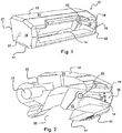
- each connector 10 is formed with a body 12 and has an first opening 14 on a second end 25.
- the second end 25 is positioned opposite a first end 27 of each of the connectors 10 each of which is adapted for engagement to or between a pair of opposing lugs 37 ( figure 6 ) which conventionally extend in such opposing pairs, from both sides of a wristwatch case 39 which houses a watch movement.
- each body 12 of each connector 10 has a upper surface 13 opposite a lower surface 17 both extending between two opposing sidewalls 18.
- a passage 28 runs in-between the two opposing sidewalls 18 of the body 12.
- the passage 28 communicates from the first opening 14 on the second end, to a second opening 30 in the lower 17 surface ( figure 4A and 5A ).
- This passage 28 and is adapted for operative engagement with each engagement end of the two sections of a two-piece watch band 24, or for passage therethrough of a single piece watch band 32 such as in figures 5A and figure 6 .
- Grooves 16 depend into corresponding positions, upon the sidewalls 18 on opposing sides of the passage 28.
- the grooves 16 depend a depth into the opposing sidewalls to form a recessed surface 15 in corresponding positions on both opposing sidewalls 18 within the passage 28.
- Both grooves 16 correspond in their respective position on each opposing sidewall 18 such that they mirror each other.
- the grooves 16 have a width W ( figure 2 ) defined by a diameter of the groove 16. This width W is largest at an intersection of each groove 16 with the first opening 14 on the second side of the body 12, and the width W tapers to a smaller diameter of each groove 16, adjacent opposing holes 22 in the sidewall 18.
- the holes 22 are configured to operatively engage the ends or spring loaded pins 21 of the spring bar 20 therein ( figure 3 ).
- This tapering shown best in figure 8 extends from a larger first distance D1 between the opposing recessed surfaces 15, where both opposing recessed surfaces 15 intersect the first opening 14, to a narrower second distance D2 between the opposing recessed surfaces 15 depending into the sidewalls 18, at or adjacent both respective holes 22 formed within the grooves 16 in both respective sidewalls 18.
- the tapering of the width between the recessed surfaces 15 of the two grooves 16, and the resulting decreasing distance between the two opposing recessed surfaces 15 as the grooves 16 approach the holes 22, defines a secondary pathway within the passage which narrows as it approaches the holes 22.
- This narrowing is configured for a sliding insertion of a spring bar 20 ( fig 3 ) along the opposing grooves 16, from the first opening 14 toward the holes 22, to achieve operative engagement of the two end pins 21 of the spring bar 20 within formed holes 22.
- the connector 10 body 12 so configured defines a compressive path for the ends of the spring bar 20 for compressing an subsequent engagement of the two spring loaded projecting ends of the spring bar 20 into the holes 22, without any tools. This may be accomplished while the spring bar 20 is engaged with a wrapped connection end of the ( figure 4A ) watch band 24, which is then slid along the path of the opposing grooves 16 in corresponding positions in both sidewalls 18, while both ends of the spring bar contacting one of the recessed surfaces 15 in each respective groove 16.
- both projecting portions 21 or ends of the spring bar 20 are thereby compressed by contact with and the decreasing distance between, the two recessed surfaces 15.
- the narrowing of the width of both grooves 16 concurrently acts as a funnel or guide for the translating spring bar 20 with the band 24 wrapped around it as in figure 4A , such that the projecting portions 21 of the spring bar 20 are guided to engagements with the holes 22, without the user needing to view the progression of the spring bar 20 during the procedure which is normally required and conventionally takes good vision or magnifying lenses.
- FIG 4a This engaged configuration is shown in figure 4a , which shows the spring bar 20 engaged through each connection end of each section forming the two piece band 24, and with both projecting ends of the spring bar 20 engaged in the holes 22. Also shown is the tertiary engagement 41 of a formed bulbous portion 26 of the connection ends of the sections of the watch band 24. This bulbous portion 26 forms as the watch band 24 wraps around the spring bar 20, secured within a taller second portion 29 the passage 28 formed by and communicating from the second opening 30 to the passage 28.
- This tertiary engagement 41 occurs after the end of the band 24, wrapped around the spring bar 20, has been pushed through a shorter first portion 31 of the passage 28 between a top and bottom surface of the passage 28 located at the first opening 14.
- the passage 28 runs to a larger or taller second portion 29 aligned with the second opening 30.
- a secondary capture/retention methodology may also be provided in addition to that of the tip of the spring bar 20 in the hole 22 on the sidewall 18 surrounding the hole 22.
- a positive capture and retention of the spring bar 20 is further enhanced through a secondary engagement where a flange 21A ( figure 3 )at the ends of the spring bar 20 operatively engages within a concentric annular recession 23 depending into the sidewall 18 and surrounding hole 22, as shown in figure 2 .
- FIG 2 Also shown in figure 2 , is the perspective sectional view through the body 12 of the connector 10 such as in figure 1 and 3 .
- the spring bar holes 22 can be seen at the narrowest point of separation between tapering recessed surfaces 15 of the two opposing grooves 16.
- figure 3 shows the connector 10 of figure 1 with a spring bar 20 having both spring loaded tips, engaged with the holes 22 at this narrowed position along and between the opposing recessed surfaces 15 of the two grooves 16 defining a ramp.
- FIGS 4 and 4A there is shown one section of a two-piece band 24 communicating through the passage 28 from the first opening 14 of the body 12 of the connector 10.
- the bulbous portion 26 has decompressed to a size exceeding the height of the shorter first portion 31 of the passage 28.
- connection ends of each section forming the two piece watch band 24, are held in engagement with the connector 12 by a tertiary engagement 41 ( Figure 4A ) within the passage 28 as shown formed by the bulbous portion 26 at each connection end of each section forming the two piece strap 24 having expanded to a diameter wider than the shorter first portion 31 of the passage 28.
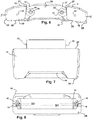
- the first end 27 of the body 12 of each connector 10, on the opposite side from the second end 25 having the first opening 14, is adapted for engagement with the case 39 holding a movement of a wristwatch such as in figure 6 .
- An axial passage 33 is shown in figures 4A, 5A , and 6 , adapting the first end 27 of the body 12 as an example of such an engagement, where a screw or pin 35 runs through the axial passage 33 and engages lugs 37 ( figure 6 ) on the case 39 of the wristwatch in a conventional fashion which is well known.
- Figures 5 and 5A depict the body 12 of each connector 10 having a single piece watch band 32 communicating through the passage 28, formed between the two sidewalls 18 of the body 12 of the connector 10. As noted this passage 28 curves and runs from the first opening 14 to the second opening 30. Shown in figure 6 is the serpentine pathway formed for a single piece watch band through each passage 28 of both connectors 10 which is followed by a single piece watch band 32 through the depicted body 12 of each connector 10 and in-between both by exiting the second opening 30 of one connector and re-entering the second opening 30 of the other connector 10, after passage adjacent the watch case 39 therebetween.
- one connector 10 is positioned and operatively engaged on both sides of a watch case 39 as shown in the depiction in figure 6 .
- two of the connectors 10 herein each having first ends of the body 12 adapted for engagement to the case 39 are connected thereto such as with the lugs 37 extending on opposing sides of a watch case 39 and using a pin 35 or screw or the like.
- the watch can be engaged with either a single piece elongated band 32 which follows the serpentine path formed by both passages 28 in the body 12 of both connectors 10 and across a back surface of the watch case 39, or, a two-piece band 24 can be engaged.
- a two-piece band 24 can be engaged.
- one connection end of each of the sections forming the two-piece band 24 is engaged within the passage 28 in the body 12 of each connector 10 as depicted in figure 4A , where the spring loaded ends of the spring bar 20 seat into the holes 22.
- FIG 7 a top view of an upper surface 13 of each body 12 of each of the connectors 10 herein.
- the axial passage 33 adapts the first end 25 of the body 12 of each connector 10 for engagement to one side of a watch case 39, such as in figure 6 , although the first end 27 can be adapted for other engagements depending on the configuration of the watch case 39.
- the first opening 14 at the second end 25 of the body 12 for communication of either the single piece watch band 32 or one section of the two piece watch band 24 therethrough and into the passage 28.
- the first opening 14 communicating with the passage 28 at the second end 25 of the body 12 of the connector 10.
- the distance between the opposing corresponding recessed surfaces 15 defining the depth of both grooves 16 into opposing sidewalls 18, decreases from a larger distance D1 at or adjacent the first opening 14, to a narrower distance D2 at or adjacent the holes 22.
- the width W ( figure 2 ) of the grooves 16 decreases from a wider width at the intersection with the first opening 14 to a narrower width at or adjacent the holes 22.
Landscapes
- Physics & Mathematics (AREA)
- General Physics & Mathematics (AREA)
- Buckles (AREA)
- Purses, Travelling Bags, Baskets, Or Suitcases (AREA)
- Coupling Device And Connection With Printed Circuit (AREA)
Applications Claiming Priority (3)
| Application Number | Priority Date | Filing Date | Title |
|---|---|---|---|
| US201662418670P | 2016-11-07 | 2016-11-07 | |
| US15/717,639 US10149519B2 (en) | 2016-11-07 | 2017-09-27 | Dual engagement watch strap connector |
| PCT/US2017/060020 WO2018085707A2 (en) | 2016-11-07 | 2017-11-03 | Dual engagement watch strap connector |
Publications (3)
| Publication Number | Publication Date |
|---|---|
| EP3534746A2 EP3534746A2 (en) | 2019-09-11 |
| EP3534746A4 EP3534746A4 (en) | 2020-07-08 |
| EP3534746B1 true EP3534746B1 (en) | 2021-09-08 |
Family
ID=62065026
Family Applications (1)
| Application Number | Title | Priority Date | Filing Date |
|---|---|---|---|
| EP17867621.9A Not-in-force EP3534746B1 (en) | 2016-11-07 | 2017-11-03 | Dual engagement watch strap connector |
Country Status (4)
| Country | Link |
|---|---|
| US (1) | US10149519B2 (enExample) |
| EP (1) | EP3534746B1 (enExample) |
| JP (1) | JP2019535348A (enExample) |
| WO (1) | WO2018085707A2 (enExample) |
Families Citing this family (7)
| Publication number | Priority date | Publication date | Assignee | Title |
|---|---|---|---|---|
| USD749460S1 (en) * | 2014-08-11 | 2016-02-16 | Apple Inc. | Band attachment |
| USD907524S1 (en) * | 2019-01-28 | 2021-01-12 | Sol-Light, Llc. | Watch strap connector |
| USD906870S1 (en) * | 2019-01-28 | 2021-01-05 | Sol-Light, Llc | Watch strap connector |
| USD906871S1 (en) * | 2019-01-28 | 2021-01-05 | Sol-Light, Llc | Watch strap connector |
| CN110376874A (zh) * | 2019-07-19 | 2019-10-25 | 歌尔科技有限公司 | 腕戴设备 |
| CN113311689B (zh) * | 2020-02-26 | 2022-08-12 | Oppo广东移动通信有限公司 | 壳体及其制备方法、表体和可穿戴设备 |
| JP7517027B2 (ja) * | 2020-09-25 | 2024-07-17 | セイコーエプソン株式会社 | バンドおよび時計 |
Family Cites Families (10)
| Publication number | Priority date | Publication date | Assignee | Title |
|---|---|---|---|---|
| US4266326A (en) | 1979-08-06 | 1981-05-12 | Hong Lai F | Watchband connector |
| JPS5895715U (ja) * | 1981-12-23 | 1983-06-29 | カシオ計算機株式会社 | 腕時計ケ−スのバネ棒取付部の構造 |
| JPS60104787U (ja) * | 1983-12-21 | 1985-07-17 | 株式会社ヨコオ | 腕時計 |
| CH654714GA3 (enExample) * | 1984-05-25 | 1986-03-14 | ||
| JPH08238116A (ja) * | 1995-03-07 | 1996-09-17 | Casio Comput Co Ltd | バンド取付構造 |
| US5943302A (en) * | 1996-11-13 | 1999-08-24 | Bonneville Watches | Modular wristwatch assembly and case assembly for same |
| JP2010035797A (ja) | 2008-08-05 | 2010-02-18 | Casio Comput Co Ltd | 腕時計のバンド取付構造 |
| JP5831846B2 (ja) * | 2012-02-20 | 2015-12-09 | カシオ計算機株式会社 | バンドおよび腕時計 |
| US9092012B2 (en) | 2012-10-15 | 2015-07-28 | Timex Group Usa, Inc. | Coupling assembly for coupling a wristworn device to a strap |
| KR102329820B1 (ko) * | 2015-01-29 | 2021-11-23 | 삼성전자주식회사 | 신체 장착형 장치 |
-
2017
- 2017-09-27 US US15/717,639 patent/US10149519B2/en active Active
- 2017-11-03 EP EP17867621.9A patent/EP3534746B1/en not_active Not-in-force
- 2017-11-03 WO PCT/US2017/060020 patent/WO2018085707A2/en not_active Ceased
- 2017-11-03 JP JP2019517967A patent/JP2019535348A/ja active Pending
Also Published As
| Publication number | Publication date |
|---|---|
| WO2018085707A2 (en) | 2018-05-11 |
| EP3534746A2 (en) | 2019-09-11 |
| JP2019535348A (ja) | 2019-12-12 |
| US20180125179A1 (en) | 2018-05-10 |
| WO2018085707A3 (en) | 2019-06-06 |
| US10149519B2 (en) | 2018-12-11 |
| EP3534746A4 (en) | 2020-07-08 |
Similar Documents
| Publication | Publication Date | Title |
|---|---|---|
| EP3534746B1 (en) | Dual engagement watch strap connector | |
| US20140250637A1 (en) | Spring Bar with Radial Pin | |
| US8510897B2 (en) | Windshield wiper arm connector | |
| JP6434742B2 (ja) | 2芯型光コネクタプラグ | |
| US20140353349A1 (en) | Removable connecting device of a wrist band | |
| EP2918187B1 (en) | Buckle | |
| WO2016072330A1 (ja) | 光コネクタ、ピンキーパー、ピン挿入用治具、拡張部材及びピン挿入具 | |
| CN107683097A (zh) | 表带及具有该表带的手表 | |
| US20160054585A1 (en) | Twist and pivot eyeglasses | |
| JPH06140101A (ja) | コネクタ | |
| JP6263523B2 (ja) | 眼鏡フレーム用伸縮式ヒンジ | |
| US20040184358A1 (en) | Band link coupling pin, band, and wristwatch | |
| EP3482249B1 (en) | Device for attaching component parts of spectacles frames and spectacles comprising said attachment device | |
| US9318098B2 (en) | Tube system and life tube adaptor for a hearing aid | |
| US9160108B2 (en) | Lever connector | |
| EP1524547B1 (en) | Elastic hinge particularly for monobloc temples | |
| JP5479797B2 (ja) | 圧接カバーを備えた光ファイバ用コネクタ | |
| JP5497854B2 (ja) | 装身具用連結具 | |
| JP2011000317A (ja) | 連結具 | |
| JP2007082597A (ja) | 連結装置、バンドおよび時計 | |
| JP2016090892A (ja) | 光コネクタ、ピンキーパー及びピン挿入用治具 | |
| KR20060093685A (ko) | 피어싱 장신구 | |
| CN211298658U (zh) | 一种手表 | |
| KR101236924B1 (ko) | 안테나 결합구조 | |
| US20200200980A1 (en) | Optical connector |
Legal Events
| Date | Code | Title | Description |
|---|---|---|---|
| STAA | Information on the status of an ep patent application or granted ep patent |
Free format text: STATUS: THE INTERNATIONAL PUBLICATION HAS BEEN MADE |
|
| PUAI | Public reference made under article 153(3) epc to a published international application that has entered the european phase |
Free format text: ORIGINAL CODE: 0009012 |
|
| STAA | Information on the status of an ep patent application or granted ep patent |
Free format text: STATUS: REQUEST FOR EXAMINATION WAS MADE |
|
| 17P | Request for examination filed |
Effective date: 20190506 |
|
| AK | Designated contracting states |
Kind code of ref document: A2 Designated state(s): AL AT BE BG CH CY CZ DE DK EE ES FI FR GB GR HR HU IE IS IT LI LT LU LV MC MK MT NL NO PL PT RO RS SE SI SK SM TR |
|
| AX | Request for extension of the european patent |
Extension state: BA ME |
|
| DAV | Request for validation of the european patent (deleted) | ||
| DAX | Request for extension of the european patent (deleted) | ||
| A4 | Supplementary search report drawn up and despatched |
Effective date: 20200605 |
|
| RIC1 | Information provided on ipc code assigned before grant |
Ipc: G04B 37/14 20060101ALI20200529BHEP Ipc: A44C 5/16 20060101AFI20200529BHEP Ipc: A44C 5/14 20060101ALI20200529BHEP |
|
| GRAP | Despatch of communication of intention to grant a patent |
Free format text: ORIGINAL CODE: EPIDOSNIGR1 |
|
| STAA | Information on the status of an ep patent application or granted ep patent |
Free format text: STATUS: GRANT OF PATENT IS INTENDED |
|
| INTG | Intention to grant announced |
Effective date: 20210416 |
|
| GRAS | Grant fee paid |
Free format text: ORIGINAL CODE: EPIDOSNIGR3 |
|
| GRAA | (expected) grant |
Free format text: ORIGINAL CODE: 0009210 |
|
| STAA | Information on the status of an ep patent application or granted ep patent |
Free format text: STATUS: THE PATENT HAS BEEN GRANTED |
|
| AK | Designated contracting states |
Kind code of ref document: B1 Designated state(s): AL AT BE BG CH CY CZ DE DK EE ES FI FR GB GR HR HU IE IS IT LI LT LU LV MC MK MT NL NO PL PT RO RS SE SI SK SM TR |
|
| REG | Reference to a national code |
Ref country code: GB Ref legal event code: FG4D |
|
| REG | Reference to a national code |
Ref country code: AT Ref legal event code: REF Ref document number: 1427739 Country of ref document: AT Kind code of ref document: T Effective date: 20210915 Ref country code: CH Ref legal event code: EP |
|
| REG | Reference to a national code |
Ref country code: IE Ref legal event code: FG4D |
|
| REG | Reference to a national code |
Ref country code: DE Ref legal event code: R096 Ref document number: 602017045850 Country of ref document: DE |
|
| REG | Reference to a national code |
Ref country code: LT Ref legal event code: MG9D |
|
| REG | Reference to a national code |
Ref country code: NL Ref legal event code: MP Effective date: 20210908 |
|
| PG25 | Lapsed in a contracting state [announced via postgrant information from national office to epo] |
Ref country code: RS Free format text: LAPSE BECAUSE OF FAILURE TO SUBMIT A TRANSLATION OF THE DESCRIPTION OR TO PAY THE FEE WITHIN THE PRESCRIBED TIME-LIMIT Effective date: 20210908 Ref country code: SE Free format text: LAPSE BECAUSE OF FAILURE TO SUBMIT A TRANSLATION OF THE DESCRIPTION OR TO PAY THE FEE WITHIN THE PRESCRIBED TIME-LIMIT Effective date: 20210908 Ref country code: HR Free format text: LAPSE BECAUSE OF FAILURE TO SUBMIT A TRANSLATION OF THE DESCRIPTION OR TO PAY THE FEE WITHIN THE PRESCRIBED TIME-LIMIT Effective date: 20210908 Ref country code: FI Free format text: LAPSE BECAUSE OF FAILURE TO SUBMIT A TRANSLATION OF THE DESCRIPTION OR TO PAY THE FEE WITHIN THE PRESCRIBED TIME-LIMIT Effective date: 20210908 Ref country code: ES Free format text: LAPSE BECAUSE OF FAILURE TO SUBMIT A TRANSLATION OF THE DESCRIPTION OR TO PAY THE FEE WITHIN THE PRESCRIBED TIME-LIMIT Effective date: 20210908 Ref country code: LT Free format text: LAPSE BECAUSE OF FAILURE TO SUBMIT A TRANSLATION OF THE DESCRIPTION OR TO PAY THE FEE WITHIN THE PRESCRIBED TIME-LIMIT Effective date: 20210908 Ref country code: BG Free format text: LAPSE BECAUSE OF FAILURE TO SUBMIT A TRANSLATION OF THE DESCRIPTION OR TO PAY THE FEE WITHIN THE PRESCRIBED TIME-LIMIT Effective date: 20211208 Ref country code: NO Free format text: LAPSE BECAUSE OF FAILURE TO SUBMIT A TRANSLATION OF THE DESCRIPTION OR TO PAY THE FEE WITHIN THE PRESCRIBED TIME-LIMIT Effective date: 20211208 |
|
| REG | Reference to a national code |
Ref country code: AT Ref legal event code: MK05 Ref document number: 1427739 Country of ref document: AT Kind code of ref document: T Effective date: 20210908 |
|
| PG25 | Lapsed in a contracting state [announced via postgrant information from national office to epo] |
Ref country code: LV Free format text: LAPSE BECAUSE OF FAILURE TO SUBMIT A TRANSLATION OF THE DESCRIPTION OR TO PAY THE FEE WITHIN THE PRESCRIBED TIME-LIMIT Effective date: 20210908 Ref country code: GR Free format text: LAPSE BECAUSE OF FAILURE TO SUBMIT A TRANSLATION OF THE DESCRIPTION OR TO PAY THE FEE WITHIN THE PRESCRIBED TIME-LIMIT Effective date: 20211209 |
|
| PG25 | Lapsed in a contracting state [announced via postgrant information from national office to epo] |
Ref country code: AT Free format text: LAPSE BECAUSE OF FAILURE TO SUBMIT A TRANSLATION OF THE DESCRIPTION OR TO PAY THE FEE WITHIN THE PRESCRIBED TIME-LIMIT Effective date: 20210908 |
|
| PG25 | Lapsed in a contracting state [announced via postgrant information from national office to epo] |
Ref country code: IS Free format text: LAPSE BECAUSE OF FAILURE TO SUBMIT A TRANSLATION OF THE DESCRIPTION OR TO PAY THE FEE WITHIN THE PRESCRIBED TIME-LIMIT Effective date: 20220108 Ref country code: SM Free format text: LAPSE BECAUSE OF FAILURE TO SUBMIT A TRANSLATION OF THE DESCRIPTION OR TO PAY THE FEE WITHIN THE PRESCRIBED TIME-LIMIT Effective date: 20210908 Ref country code: SK Free format text: LAPSE BECAUSE OF FAILURE TO SUBMIT A TRANSLATION OF THE DESCRIPTION OR TO PAY THE FEE WITHIN THE PRESCRIBED TIME-LIMIT Effective date: 20210908 Ref country code: RO Free format text: LAPSE BECAUSE OF FAILURE TO SUBMIT A TRANSLATION OF THE DESCRIPTION OR TO PAY THE FEE WITHIN THE PRESCRIBED TIME-LIMIT Effective date: 20210908 Ref country code: PT Free format text: LAPSE BECAUSE OF FAILURE TO SUBMIT A TRANSLATION OF THE DESCRIPTION OR TO PAY THE FEE WITHIN THE PRESCRIBED TIME-LIMIT Effective date: 20220110 Ref country code: PL Free format text: LAPSE BECAUSE OF FAILURE TO SUBMIT A TRANSLATION OF THE DESCRIPTION OR TO PAY THE FEE WITHIN THE PRESCRIBED TIME-LIMIT Effective date: 20210908 Ref country code: NL Free format text: LAPSE BECAUSE OF FAILURE TO SUBMIT A TRANSLATION OF THE DESCRIPTION OR TO PAY THE FEE WITHIN THE PRESCRIBED TIME-LIMIT Effective date: 20210908 Ref country code: EE Free format text: LAPSE BECAUSE OF FAILURE TO SUBMIT A TRANSLATION OF THE DESCRIPTION OR TO PAY THE FEE WITHIN THE PRESCRIBED TIME-LIMIT Effective date: 20210908 Ref country code: CZ Free format text: LAPSE BECAUSE OF FAILURE TO SUBMIT A TRANSLATION OF THE DESCRIPTION OR TO PAY THE FEE WITHIN THE PRESCRIBED TIME-LIMIT Effective date: 20210908 Ref country code: AL Free format text: LAPSE BECAUSE OF FAILURE TO SUBMIT A TRANSLATION OF THE DESCRIPTION OR TO PAY THE FEE WITHIN THE PRESCRIBED TIME-LIMIT Effective date: 20210908 |
|
| REG | Reference to a national code |
Ref country code: DE Ref legal event code: R097 Ref document number: 602017045850 Country of ref document: DE |
|
| PG25 | Lapsed in a contracting state [announced via postgrant information from national office to epo] |
Ref country code: MC Free format text: LAPSE BECAUSE OF FAILURE TO SUBMIT A TRANSLATION OF THE DESCRIPTION OR TO PAY THE FEE WITHIN THE PRESCRIBED TIME-LIMIT Effective date: 20210908 |
|
| PLBE | No opposition filed within time limit |
Free format text: ORIGINAL CODE: 0009261 |
|
| REG | Reference to a national code |
Ref country code: CH Ref legal event code: PL |
|
| STAA | Information on the status of an ep patent application or granted ep patent |
Free format text: STATUS: NO OPPOSITION FILED WITHIN TIME LIMIT |
|
| PG25 | Lapsed in a contracting state [announced via postgrant information from national office to epo] |
Ref country code: LU Free format text: LAPSE BECAUSE OF NON-PAYMENT OF DUE FEES Effective date: 20211103 Ref country code: DK Free format text: LAPSE BECAUSE OF FAILURE TO SUBMIT A TRANSLATION OF THE DESCRIPTION OR TO PAY THE FEE WITHIN THE PRESCRIBED TIME-LIMIT Effective date: 20210908 Ref country code: BE Free format text: LAPSE BECAUSE OF NON-PAYMENT OF DUE FEES Effective date: 20211130 |
|
| REG | Reference to a national code |
Ref country code: BE Ref legal event code: MM Effective date: 20211130 |
|
| 26N | No opposition filed |
Effective date: 20220609 |
|
| PG25 | Lapsed in a contracting state [announced via postgrant information from national office to epo] |
Ref country code: SI Free format text: LAPSE BECAUSE OF FAILURE TO SUBMIT A TRANSLATION OF THE DESCRIPTION OR TO PAY THE FEE WITHIN THE PRESCRIBED TIME-LIMIT Effective date: 20210908 |
|
| PG25 | Lapsed in a contracting state [announced via postgrant information from national office to epo] |
Ref country code: IE Free format text: LAPSE BECAUSE OF NON-PAYMENT OF DUE FEES Effective date: 20211103 |
|
| PG25 | Lapsed in a contracting state [announced via postgrant information from national office to epo] |
Ref country code: FR Free format text: LAPSE BECAUSE OF NON-PAYMENT OF DUE FEES Effective date: 20211108 |
|
| PG25 | Lapsed in a contracting state [announced via postgrant information from national office to epo] |
Ref country code: IT Free format text: LAPSE BECAUSE OF FAILURE TO SUBMIT A TRANSLATION OF THE DESCRIPTION OR TO PAY THE FEE WITHIN THE PRESCRIBED TIME-LIMIT Effective date: 20210908 |
|
| PG25 | Lapsed in a contracting state [announced via postgrant information from national office to epo] |
Ref country code: CY Free format text: LAPSE BECAUSE OF FAILURE TO SUBMIT A TRANSLATION OF THE DESCRIPTION OR TO PAY THE FEE WITHIN THE PRESCRIBED TIME-LIMIT Effective date: 20210908 |
|
| PG25 | Lapsed in a contracting state [announced via postgrant information from national office to epo] |
Ref country code: LI Free format text: LAPSE BECAUSE OF NON-PAYMENT OF DUE FEES Effective date: 20220701 Ref country code: HU Free format text: LAPSE BECAUSE OF FAILURE TO SUBMIT A TRANSLATION OF THE DESCRIPTION OR TO PAY THE FEE WITHIN THE PRESCRIBED TIME-LIMIT; INVALID AB INITIO Effective date: 20171103 Ref country code: CH Free format text: LAPSE BECAUSE OF NON-PAYMENT OF DUE FEES Effective date: 20220701 |
|
| PGFP | Annual fee paid to national office [announced via postgrant information from national office to epo] |
Ref country code: GB Payment date: 20230914 Year of fee payment: 7 |
|
| PGFP | Annual fee paid to national office [announced via postgrant information from national office to epo] |
Ref country code: DE Payment date: 20230906 Year of fee payment: 7 |
|
| PG25 | Lapsed in a contracting state [announced via postgrant information from national office to epo] |
Ref country code: MK Free format text: LAPSE BECAUSE OF FAILURE TO SUBMIT A TRANSLATION OF THE DESCRIPTION OR TO PAY THE FEE WITHIN THE PRESCRIBED TIME-LIMIT Effective date: 20210908 |
|
| PG25 | Lapsed in a contracting state [announced via postgrant information from national office to epo] |
Ref country code: TR Free format text: LAPSE BECAUSE OF FAILURE TO SUBMIT A TRANSLATION OF THE DESCRIPTION OR TO PAY THE FEE WITHIN THE PRESCRIBED TIME-LIMIT Effective date: 20210908 |
|
| PG25 | Lapsed in a contracting state [announced via postgrant information from national office to epo] |
Ref country code: MT Free format text: LAPSE BECAUSE OF FAILURE TO SUBMIT A TRANSLATION OF THE DESCRIPTION OR TO PAY THE FEE WITHIN THE PRESCRIBED TIME-LIMIT Effective date: 20210908 |
|
| REG | Reference to a national code |
Ref country code: DE Ref legal event code: R119 Ref document number: 602017045850 Country of ref document: DE |
|
| GBPC | Gb: european patent ceased through non-payment of renewal fee |
Effective date: 20241103 |
|
| PG25 | Lapsed in a contracting state [announced via postgrant information from national office to epo] |
Ref country code: DE Free format text: LAPSE BECAUSE OF NON-PAYMENT OF DUE FEES Effective date: 20250603 |
|
| PG25 | Lapsed in a contracting state [announced via postgrant information from national office to epo] |
Ref country code: GB Free format text: LAPSE BECAUSE OF NON-PAYMENT OF DUE FEES Effective date: 20241103 |