EP3534679A1 - X-ray generator and x-ray analysis device - Google Patents
X-ray generator and x-ray analysis device Download PDFInfo
- Publication number
- EP3534679A1 EP3534679A1 EP19159575.0A EP19159575A EP3534679A1 EP 3534679 A1 EP3534679 A1 EP 3534679A1 EP 19159575 A EP19159575 A EP 19159575A EP 3534679 A1 EP3534679 A1 EP 3534679A1
- Authority
- EP
- European Patent Office
- Prior art keywords
- ray
- line
- reflecting mirror
- multilayer film
- mirror
- Prior art date
- Legal status (The legal status is an assumption and is not a legal conclusion. Google has not performed a legal analysis and makes no representation as to the accuracy of the status listed.)
- Granted
Links
Images



Classifications
-
- H—ELECTRICITY
- H05—ELECTRIC TECHNIQUES NOT OTHERWISE PROVIDED FOR
- H05G—X-RAY TECHNIQUE
- H05G1/00—X-ray apparatus involving X-ray tubes; Circuits therefor
- H05G1/02—Constructional details
-
- G—PHYSICS
- G21—NUCLEAR PHYSICS; NUCLEAR ENGINEERING
- G21K—HANDLING OF PARTICLES OR IONISING RADIATION NOT OTHERWISE PROVIDED FOR; IRRADIATION DEVICES; GAMMA RAY OR X-RAY MICROSCOPES
- G21K1/00—Arrangements for handling particles or ionising radiation, e.g. focusing or moderating
- G21K1/06—Arrangements for handling particles or ionising radiation, e.g. focusing or moderating using diffraction, refraction or reflection, e.g. monochromators
- G21K1/067—Arrangements for handling particles or ionising radiation, e.g. focusing or moderating using diffraction, refraction or reflection, e.g. monochromators using surface reflection, e.g. grazing incidence mirrors, gratings
-
- G—PHYSICS
- G01—MEASURING; TESTING
- G01N—INVESTIGATING OR ANALYSING MATERIALS BY DETERMINING THEIR CHEMICAL OR PHYSICAL PROPERTIES
- G01N23/00—Investigating or analysing materials by the use of wave or particle radiation, e.g. X-rays or neutrons, not covered by groups G01N3/00 – G01N17/00, G01N21/00 or G01N22/00
-
- G—PHYSICS
- G01—MEASURING; TESTING
- G01N—INVESTIGATING OR ANALYSING MATERIALS BY DETERMINING THEIR CHEMICAL OR PHYSICAL PROPERTIES
- G01N23/00—Investigating or analysing materials by the use of wave or particle radiation, e.g. X-rays or neutrons, not covered by groups G01N3/00 – G01N17/00, G01N21/00 or G01N22/00
- G01N23/20—Investigating or analysing materials by the use of wave or particle radiation, e.g. X-rays or neutrons, not covered by groups G01N3/00 – G01N17/00, G01N21/00 or G01N22/00 by using diffraction of the radiation by the materials, e.g. for investigating crystal structure; by using scattering of the radiation by the materials, e.g. for investigating non-crystalline materials; by using reflection of the radiation by the materials
- G01N23/201—Investigating or analysing materials by the use of wave or particle radiation, e.g. X-rays or neutrons, not covered by groups G01N3/00 – G01N17/00, G01N21/00 or G01N22/00 by using diffraction of the radiation by the materials, e.g. for investigating crystal structure; by using scattering of the radiation by the materials, e.g. for investigating non-crystalline materials; by using reflection of the radiation by the materials by measuring small-angle scattering
-
- G—PHYSICS
- G21—NUCLEAR PHYSICS; NUCLEAR ENGINEERING
- G21K—HANDLING OF PARTICLES OR IONISING RADIATION NOT OTHERWISE PROVIDED FOR; IRRADIATION DEVICES; GAMMA RAY OR X-RAY MICROSCOPES
- G21K1/00—Arrangements for handling particles or ionising radiation, e.g. focusing or moderating
-
- G—PHYSICS
- G21—NUCLEAR PHYSICS; NUCLEAR ENGINEERING
- G21K—HANDLING OF PARTICLES OR IONISING RADIATION NOT OTHERWISE PROVIDED FOR; IRRADIATION DEVICES; GAMMA RAY OR X-RAY MICROSCOPES
- G21K1/00—Arrangements for handling particles or ionising radiation, e.g. focusing or moderating
- G21K1/02—Arrangements for handling particles or ionising radiation, e.g. focusing or moderating using diaphragms, collimators
- G21K1/025—Arrangements for handling particles or ionising radiation, e.g. focusing or moderating using diaphragms, collimators using multiple collimators, e.g. Bucky screens; other devices for eliminating undesired or dispersed radiation
-
- G—PHYSICS
- G21—NUCLEAR PHYSICS; NUCLEAR ENGINEERING
- G21K—HANDLING OF PARTICLES OR IONISING RADIATION NOT OTHERWISE PROVIDED FOR; IRRADIATION DEVICES; GAMMA RAY OR X-RAY MICROSCOPES
- G21K1/00—Arrangements for handling particles or ionising radiation, e.g. focusing or moderating
- G21K1/06—Arrangements for handling particles or ionising radiation, e.g. focusing or moderating using diffraction, refraction or reflection, e.g. monochromators
-
- G—PHYSICS
- G01—MEASURING; TESTING
- G01N—INVESTIGATING OR ANALYSING MATERIALS BY DETERMINING THEIR CHEMICAL OR PHYSICAL PROPERTIES
- G01N2223/00—Investigating materials by wave or particle radiation
- G01N2223/30—Accessories, mechanical or electrical features
- G01N2223/308—Accessories, mechanical or electrical features support of radiation source
-
- G—PHYSICS
- G21—NUCLEAR PHYSICS; NUCLEAR ENGINEERING
- G21K—HANDLING OF PARTICLES OR IONISING RADIATION NOT OTHERWISE PROVIDED FOR; IRRADIATION DEVICES; GAMMA RAY OR X-RAY MICROSCOPES
- G21K1/00—Arrangements for handling particles or ionising radiation, e.g. focusing or moderating
- G21K1/06—Arrangements for handling particles or ionising radiation, e.g. focusing or moderating using diffraction, refraction or reflection, e.g. monochromators
- G21K1/062—Devices having a multilayer structure
-
- G—PHYSICS
- G21—NUCLEAR PHYSICS; NUCLEAR ENGINEERING
- G21K—HANDLING OF PARTICLES OR IONISING RADIATION NOT OTHERWISE PROVIDED FOR; IRRADIATION DEVICES; GAMMA RAY OR X-RAY MICROSCOPES
- G21K2201/00—Arrangements for handling radiation or particles
- G21K2201/06—Arrangements for handling radiation or particles using diffractive, refractive or reflecting elements
- G21K2201/061—Arrangements for handling radiation or particles using diffractive, refractive or reflecting elements characterised by a multilayer structure
Definitions
- the present invention relates to an X-ray generator and an X-ray analysis device, and particularly to a technique for providing a focused X-ray beam.
- An X-ray generator capable of radiating a focused X-ray beam having a small beam size onto a desired position (e.g., a position where a sample is disposed) has been used.
- JP2015-520384A discloses a dual mode scattering system or a dual mode diffraction system.
- a radiation source 214 is a line source of radiation, and an X-ray beam from the radiation source 214 passes through a second opening of an aperture 236 and interacts with both a first surface 222 and a second surface 224 of a KB optical system, thereby forming, for example, a two-dimensional beam 232 serving as a point beam.
- Fig. 1 in JP2015-522809A discloses a dual mode small-angle X-ray scattering system in a two-dimensional operating mode.
- JP2008-096180A discloses an X-ray optical system in which a polycapillary 36 is used to obtain a point-like X-ray beam.
- a third state in which a focused beam whose cross section is focused into a point shape is obtained is realized.
- a line X-ray source has been widely used in an X-ray diffraction measurement in view of the balance between a resolution and a sample size.
- the dual mode scattering system or the dual mode diffraction system disclosed in JP2015-520384A and JP2015-522809A includes the line X-ray source (the radiation source 214) widely used because of the reason described above .
- the X-ray beam from the radiation source 214 is limitedly selected (narrowed) by the second opening, which is, for example, a square hole; therefore, a high-intensity focused X-ray beam is not realized even when the X-ray beam that has passed through the second opening is focused.
- the polycapillary 36 is used to realize a focused X-ray beam; therefore, the divergence angle of the X-ray beam is large, leading to a reduction in resolution in X-ray diffraction measurement.
- the invention has been made in view of the problems, and it is an object of the invention to provide an X-ray generator and an X-ray analysis device that are capable of realizing with a simple configuration a focused X-ray beam whose beam size is small and whose divergence angle is small.
- the invention provides an X-ray generator and an X-ray analysis device that are capable of realizing with a simple configuration a focused X-ray beam whose beam size is small.
- Fig. 1 is a schematic view showing the configuration of an X-ray analysis device 1 according to the embodiment of the invention.
- the X-ray analysis device 1 according to the embodiment is an X-ray diffractometer device (XRD) but is not limited to this.
- the X-ray analysis device 1 may be a small-angle X-ray scattering device (SAXS) or may be other X-ray analysis devices.
- the X-ray analysis device 1 according to the embodiment includes an X-ray source portion 11, a CBO unit 12, a focusing element 13, an aperture 14, a collimator 15, a support stage 16 to support a sample 100, a two-dimensional detector 18, a goniometer 21, and a moving mechanism 22.
- An X-ray generator 2 (not shown) according to the embodiment includes the X-ray source portion 11, the CBO unit 12, the focusing element 13, the aperture 14, the collimator 15, and the moving mechanism 22.
- the X-ray generator includes not only the X-ray source portion emitting an X-ray but also an X-ray optical system portion that forms an X-ray beam to be radiated onto a sample.
- the X-ray optical system portion includes the CBO unit 12, the focusing element 13, the aperture 14, and the collimator 15.
- the collimator 15 is not essential but may be used as necessary.
- the goniometer 21 is a ⁇ - ⁇ goniometer of a horizontally disposed sample type.
- the goniometer 21 can perform 2 ⁇ scan while horizontally holding the sample 100 supported on the support stage 16. By horizontally placing the sample 100, the influence of bend of the sample 100 due to its weight can be minimized, and the risk of falling of the sample 100 can be suppressed.
- the goniometer 21 includes two arms extending from the sample 100 supported by the support stage 16 at the center.
- a typical direction of an X-ray beam that propagates from the focusing element 13 to the sample 100 is defined as an x-axis direction, and a plane that is perpendicular to the x-axis direction is defined as a yz plane.
- the X-ray source portion 11, the CBO unit 12, the focusing element 13, the aperture 14, the collimator 15, and the moving mechanism 22 are mounted on one of the arms along the x-axis direction.
- the two-dimensional detector 18 is mounted on the other arm. The two arms rotate by ⁇ in opposite directions with each other with respect to the sample 100, and thus the two-dimensional detector 18 can be rotated by 2 ⁇ when the sample 100 rotates by ⁇ with respect to an X-ray beam that is incident on the sample 100.
- the X-ray source portion 11 includes a rotor target. By radiating an electron beam whose cross section is linear onto the rotor target, X-rays are generated by a rotor target surface. Through a slit window disposed in parallel with an axis of rotation of the rotor target, an X-ray that transmits through the slit window, in the X-rays generated by the rotor target, is emitted to the outside.
- the X-ray source portion 11 can be deemed to include a line X-ray source 11A.
- the X-ray source portion 11 includes one that includes (can be deemed to include) a line X-ray source, without limiting to a rotor target, and the X-ray source portion 11 may include, for example, a sealed tube.
- the CBO (cross beam optics) unit 12 includes a slit plate 31 (not shown) including two slits 31A and 31B (not shown) on an incident side, and further includes a multilayer film mirror 12A (not shown) .
- One (31A) of the two slits 31A and 31B is for a direct beam, and the other (31B) is for a collimated beam that is monochromatically collimated by the multilayer film mirror 12A.
- the X-ray generator 2 (the X-ray optical system portion) includes the CBO unit 12 but is not limited to this. It is sufficient that the X-ray generator 2 (the X-ray optical system portion) includes an optical component including the multilayer film mirror 12A.
- a cross section of a reflecting surface of the multilayer film mirror 12A has a parabolic shape.
- the multilayer film mirror 12A is disposed such that the focus of the parabolic shape is located at the line X-ray source 11A.
- the multilayer film mirror 12A has a multilayer structure in which a characteristic X-ray (herein Cu K ⁇ X-ray) serving as a target is selectively reflected.
- a characteristic X-ray herein Cu K ⁇ X-ray
- the focusing element 13 includes a side-by-side reflecting mirror 13A (not shown) including two concave mirrors joined together.
- a side-by-side reflecting mirror 13A (not shown) including two concave mirrors joined together.
- each of cross sections of the two concave mirrors has a parabolic shape, and the collimated X-ray beam incident on the side-by-side reflecting mirror 13A is focused on a confocal point of the side-by-side reflecting mirror 13A located on the side opposite to the multilayer film mirror 12A.
- the X-ray source portion 11, the CBO unit 12, and the focusing element 13 are fixed to one another and integrated.
- the CBO unit 12 is fixed to the X-ray source portion 11, and the focusing element 13 is fixed to the CBO unit 12.
- the integrated these components are mounted on the moving mechanism 22.
- the moving mechanism 22 includes, for example, connecting portions 22A to be joined to the X-ray source portion 11, and a step motor controls the movement of the connecting portion 22A on a rail 22B.
- the moving mechanism 22 includes two connecting portions 22A and two rails 22B respectively moving the two connecting portions 22A. Details will be described later.
- the collimator 15 absorbs a scattering X-ray beam and transmits a straight traveling X-ray beam.
- the collimator 15 selectively transmits a desired focused X-ray beam of X-ray beams emitted from the focusing element 13. It is sufficient that the collimator 15 is disposed as necessary, and the collimator 15 may not be necessarily disposed.
- the two-dimensional detector 18 is a detector capable of two-dimensionally detecting an X-ray generated from the sample 100, but is not limited to this.
- the two-dimensional detector 18 may be a one-dimensional detector or a scintillation detector as necessary.
- an RxRy attachment for sample tilt alignment to be performed before in-plane measurement or reciprocal space map measurement may be mounted on the support stage 16 supporting the sample 100.
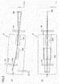
- Fig. 2 is a schematic views showing the configuration of the X-ray generator 2 according to the embodiment. As shown in Fig 2 , only main components are shown for clarity of the state of an X-ray beam.
- Fig. 2(a) is a side view of the X-ray generator 2.
- Fig. 2 (b) is a plan view of the X-ray generator 2.
- the line X-ray source 11A of the X-ray source portion 11, the slit plate 31 and the multilayer film mirror 12A of the CBO unit 12, the side-by-side reflecting mirror 13A of the focusing element 13, and the aperture 14 are shown.
- the side view of the X-ray generator 2 shows an xz plane
- the plan view of the X-ray generator 2 shows the xy plane.
- Fig. 3 is a cross-sectional view of the side-by-side reflecting mirror 13A according to the embodiment, showing the yz plane.
- the side-by-side reflecting mirror 13A includes two concave reflecting mirrors 40A and 40B.
- cross sections of reflecting surfaces of the two concave reflecting mirrors 40A and 40B each have a parabolic shape, and it is further desirable that the two concave reflecting mirrors 40A and 40B are substantially equivalent to each other.
- the two concave reflecting mirrors 40A and 40B are joined in contact with each other so as to share a join line 40C.
- the two concave reflecting mirrors 40A and 40B each have the reflecting surface serving as a concave, and the reflecting surface can be closely akin to a plane.
- the two concave reflecting mirrors 40A and 40B are joined such that the reflecting surfaces of the two concave reflecting mirrors 40A and 40B intersect with each other, and it is desirable that the two concave reflecting mirrors 40A and 40B are joined so as to be substantially at a right angle.
- the phrase "substantially at a right angle” means that an angle ⁇ formed by the reflecting surface of the concave reflecting mirror 40A and the reflecting surface of the concave reflecting mirror 40B via the join line 40C is 85° or more and 95° or less, and it is further desirable that the angle ⁇ is 88° or more and 92° or less. It is needless to say that the angle ⁇ is still desirably 90°.
- a cross section (a cross section perpendicular to the x-axis direction) of the side-by-side reflecting mirror 13A
- one (the concave reflecting mirror 40A) is disposed on the counterclockwise side and the other (the concave reflecting mirror 40B) is disposed on the clockwise side, with respect to the z-axis direction.
- the concave reflecting mirror 40A and the concave reflecting mirror 40B are disposed such that a cross section of the concave reflecting mirror 40A and a cross section of the concave reflecting mirror 40B are nearly plane symmetrical with a plane including the z-axis and the join line 40C being as a symmetry plane.
- the cross sections are plane symmetrical, but it is sufficient that the cross sections are substantially plane symmetrical. It is desirable that an angle ⁇ formed by the reflecting surface of the concave reflecting mirror 40A and the y-axis direction is substantially 45°.
- the phrase "substantially 45°” means that the angle ⁇ is 40° or more and 50° or less, and it is further desirable that the angle ⁇ is 43° or more and 47° or less. It is needless to say that the angle is still desirably 45°.
- both the focus of the parabolic shape that is the cross section of the reflecting surface of the concave reflecting mirror 40A and the focus of the parabolic shape that is the cross section of the reflecting surface of the concave reflecting mirror 40B are included in the sample 100. It is further desirable that these two focuses are as close as possible to each other, and ideally, it is desirable that these two focuses coincide with each other. However, it is sufficient that these two focuses are close to each other to such an extent as to substantially coincide with each other.
- the focus of the parabolic shape that is the cross section of the reflecting surface of the concave reflecting mirror 40A and the focus of the parabolic shape that is the cross section of the reflecting surface of the concave reflecting mirror 40B substantially coincide with each other, and the side-by-side reflecting mirror 13A according to the embodiment is a confocal reflecting mirror.
- an X-ray beam that passes through an area A shown in Fig. 3 is focused.
- the area A has substantially a square shape, and the length (diagonal) in the y-axis direction is approximately 1 mm.
- a cross-sectional shape of the multilayer film mirror 12A is represented by an imaginary line, and the length of the multilayer film mirror 12A in the y-axis direction is approximately 8 mm.
- the side-by-side reflecting mirror 13A is disposed such that an extended line of the join line 40C of the side-by-side reflecting mirror 13Apasses through the center lines of the multilayer film mirror 12A and the line X-ray source 11A as viewed inaplanview.
- the extended line of the join line 40C of the side-by-side reflecting mirror 13A coincides with the center line of the multilayer film mirror 12A and the center line of the line X-ray source 11A as viewed in a plan view; however, the invention is not limited to this, and it is sufficient that the extended line of the join line 40C substantially coincides with the center lines. It is sufficient that the extended line of the join line 40C of the side-by-side reflecting mirror 13A at least passes through the multilayer film mirror 12A and the line X-ray source 11A as viewed in a plan view.
- an X-ray beam that reaches the reflecting surface of the multilayer film mirror 12A is reflected by the reflecting surface and collimated.
- the collimated X-ray beam is focused by the side-by-side reflecting mirror 13A.
- the X-ray generator according to the embodiment can realize with a simple configuration a focused X-ray beam having a high intensity and a small beam size (focus size) by use of the line X-ray source, the multilayer film mirror, and the side-by-side reflecting mirror.
- the small beam size is 200 ⁇ m or less.
- a point-focused beam can be easily obtained by disposing the side-by-side reflecting mirror 13A in measurement using a high integrated intensity.
- a propagation direction of an X-ray is the x-axis direction as viewed in a plan view (in anxyplane), and it is easy to adjust an optical axis.
- an X-ray beam is reflected at the multilayer film mirror 12A and the side-by-side reflecting mirror 13A, and a shift in the focal position of the focused X-ray beam occurs with respect to the z-axis direction.
- the present inventors have studied that, for example, a shift of approximately 7 mm occurs in the embodiment.
- the X-ray source portion 11, the CBO unit 12, and the focusing element 13 are fixed to one another and integrated as described above.
- the moving mechanism 22 can translate the line X-ray source 11A, the multilayer film mirror 12A, and the side-by-side reflecting mirror 13A as one integrated body along an extending direction of the rail 22B by moving with the step motor the connecting portion 22A on the rail 22B.
- the extending direction of the rail 22B is along the z-axis direction. It is desirable that the extending direction (a translation direction of the moving mechanism 22) of the rail 22B coincides with the z-axis direction; however, the extending direction does not necessarily need to coincide therewith, and it is sufficient that the extending direction is a direction that intersects with the propagation direction of the X-ray beam. It is ideal that an angle formed by the extending direction and the propagation direction of the X-ray beam is 90°; however, it is sufficient that the angle is 85° or more. It is further desirable that the angle is 88° or more.
- Figs. 4A and 4B show a beam size of a focused X-ray of the X-ray generator 2 according to the embodiment.
- Fig. 4A shows a result of z-axis-direction scanning of a slit disposed at a position where a sample is disposed or in the vicinity of the position.
- Fig. 4B shows a result of y-axis-direction scanning of the slit disposed at the position where the sample is disposed or in the vicinity of the position.
- Fig. 4C shows the position where the slit is disposed in the x-axis direction.
- the scanning is performed in a state where the angle ⁇ of the goniometer 21 is 0°, that is, in a state where the X-ray source portion 11, the support stage 16, and the two-dimensional detector 18 are disposed substantially in a straight line, and the two-dimensional detector 18 detects an X-ray intensity of the focused X-ray.
- Fig. 4A shows by four curves the intensity of the focused X-ray scanning in the z-axis direction, when the position in the x-axis direction is at -50 mm, -15 mm, 0 mm, and +50 mm as shown in Fig. 4C , at the origin position in the y-axis direction.
- Fig. 4B shows by four curves the intensity of the focused X-ray scanning in the y-axis direction, when the position in the x-axis direction is at -50 mm, -15 mm, 0 mm, and +50 mm as shown in Fig. 4C , at the origin position in the z-axis direction.
- an X-ray beam whose peak intensity is low and whose peak width is wide when the position in the x-axis direction is at +50 mm and -50 mm is high in peak intensity and is narrowed in peak width when the position in the x-axis direction is the position (0 mm) where the sample is disposed.
- the peak intensity is further high and the peak width is further narrowed, so that an X-ray beam whose focus size is small can be realized and that an X-ray optical axis adjustment can be realized.
- an X-ray beam whose peak intensity is low and whose peak width is wide when the position in the x-axis direction is at +50 mm and -50 mm is high in peak intensity and is narrowed in peak width when the position in the x-axis direction is the position (0mm) where the sample is disposed.
- the peak intensity is further high and the peak width is further narrowed, so that an X-ray beam whose focus size is small can be realized and that an X-ray optical axis adjustment can be realized.
- Fig. 5 shows an experimental result of the X-ray analysis device 1 according to the embodiment.
- a focused X-ray beam whose focus size is small is realized by the X-ray generator 2, and thus spot-like reflection is confirmed in the two-dimensional scattering image shown in Fig. 5 .
- the spread of lattice points in an arc direction is confirmed, it is considered that a random component is contained.
- the sample is disposed at the focal position of the focused X-ray beam; however, the invention is not limited to this.
- the X-ray analysis device includes the X-ray generator, the detector, and the support stage supporting the sample, in which the focuses of the two concave mirrors of the side-by-side reflecting mirror each may include any point between the sample and the detector.
- the focal positions of the two concave mirrors of the side-by-side reflecting mirror each may be located between the sample and the detector.
Landscapes
- Physics & Mathematics (AREA)
- Spectroscopy & Molecular Physics (AREA)
- Engineering & Computer Science (AREA)
- General Engineering & Computer Science (AREA)
- High Energy & Nuclear Physics (AREA)
- Chemical & Material Sciences (AREA)
- Analytical Chemistry (AREA)
- Life Sciences & Earth Sciences (AREA)
- Health & Medical Sciences (AREA)
- Biochemistry (AREA)
- General Health & Medical Sciences (AREA)
- General Physics & Mathematics (AREA)
- Immunology (AREA)
- Pathology (AREA)
- Crystallography & Structural Chemistry (AREA)
- Analysing Materials By The Use Of Radiation (AREA)
Abstract
Description
- The present invention relates to an X-ray generator and an X-ray analysis device, and particularly to a technique for providing a focused X-ray beam.
- An X-ray generator capable of radiating a focused X-ray beam having a small beam size onto a desired position (e.g., a position where a sample is disposed) has been used.
-
JP2015-520384A Fig. 3A inJP2015-520384A Fig. 1 inJP2015-522809A -
JP2008-096180A - Conventionally, a line X-ray source has been widely used in an X-ray diffraction measurement in view of the balance between a resolution and a sample size.
- The dual mode scattering system or the dual mode diffraction system disclosed in
JP2015-520384A JP2015-522809A - In the X-ray optical system disclosed in
JP 2008-96180 A - The invention has been made in view of the problems, and it is an object of the invention to provide an X-ray generator and an X-ray analysis device that are capable of realizing with a simple configuration a focused X-ray beam whose beam size is small and whose divergence angle is small.
- (1) For solving the problems, an X-ray generator according to an aspect of the invention includes: a line X-ray source; a multilayer film mirror; and a side-by-side reflecting mirror including two concave mirrors joined together so as to share a join line, wherein a cross section of a reflecting surface of the multilayer film mirror has a parabolic shape and a focus of the parabolic shape is located at the line X-ray source, and cross sections of reflecting surfaces of the two concave mirrors of the side-by-side reflecting mirror each have a parabolic shape and each of focuses of the parabolic shapes is located on a side opposite to the multilayer film mirror.
- (2) The X-ray generator according to (1), wherein an extended line of the join line of the side-by-side reflecting mirror may pass through the multilayer film mirror and the line X-ray source as viewed in a plan view.
- (3) The X-ray generator according to (1) or (2), wherein mutual relative positions of the line X-ray source, the multilayer film mirror, and the side-by-side reflecting mirror may be fixed, and the X-ray generator may further include a moving mechanism that translates the line X-ray source, the multilayer film mirror, and the side-by-side reflecting mirror as one integrated body in a direction intersecting with an optical axis direction of an X-ray beam.
- (4) An X-ray analysis device according to an aspect of the invention may include: the X-ray generator according to any of (1) to (3); and a support stage that supports a sample disposed so as to include focuses of the respective two concave mirrors of the side-by-side reflecting mirror.
- (5) An X-ray analysis device according to an aspect of the invention may include: the X-ray generator according to any of (1) to (3); a detector disposed such that focal positions of the two concave mirrors of the side-by-side reflecting mirror are located on the detector; and a support stage that supports a sample disposed between the side-by-side reflecting mirror and the detector so as to be radiated with an X-ray emitted by the side-by-side reflecting mirror.
- The invention provides an X-ray generator and an X-ray analysis device that are capable of realizing with a simple configuration a focused X-ray beam whose beam size is small.
-
-
Fig. 1 is a schematic view showing the configuration of an X-ray analysis device according to an embodiment of the invention. -
Fig. 2 is a schematic views showing the configuration of an X-ray generator according to the embodiment of the invention. -
Fig. 3 is a cross-sectional view of a side-by-side reflecting mirror according to the embodiment of the invention. -
Fig. 4A shows a beam size of a focused X-ray of the X-ray generator according to the embodiment of the invention. -
Fig. 4B shows a beam size of a focused X-ray of the X-ray generator according to the embodiment of the invention. -
Fig. 4C shows a position where a slit is disposed in an x-axis direction. -
Fig. 5 shows an experimental result of the X-ray analysis device according to the embodiment of the invention. - Hereinafter, an embodiment of the invention will be described with reference to the drawings. In the drawings, dimensions, shapes, and the like may be schematically represented, compared to those in practicing aspects of the invention, for more clarity of description. However, they are illustrative only and do not limit the interpretation of the invention. In the specification and the drawings, elements similar to those described in relation to a previous drawing are denoted by the same reference numerals and signs, and a detailed description may be appropriately omitted.
-
Fig. 1 is a schematic view showing the configuration of anX-ray analysis device 1 according to the embodiment of the invention. Here, theX-ray analysis device 1 according to the embodiment is an X-ray diffractometer device (XRD) but is not limited to this. TheX-ray analysis device 1 may be a small-angle X-ray scattering device (SAXS) or may be other X-ray analysis devices. TheX-ray analysis device 1 according to the embodiment includes anX-ray source portion 11, aCBO unit 12, a focusingelement 13, anaperture 14, acollimator 15, asupport stage 16 to support asample 100, a two-dimensional detector 18, agoniometer 21, and amoving mechanism 22. An X-ray generator 2 (not shown) according to the embodiment includes theX-ray source portion 11, theCBO unit 12, the focusingelement 13, theaperture 14, thecollimator 15, and themoving mechanism 22. In the specification, the X-ray generator includes not only the X-ray source portion emitting an X-ray but also an X-ray optical system portion that forms an X-ray beam to be radiated onto a sample. Here, the X-ray optical system portion includes theCBO unit 12, the focusingelement 13, theaperture 14, and thecollimator 15. However, thecollimator 15 is not essential but may be used as necessary. - The
goniometer 21 is a θ-θ goniometer of a horizontally disposed sample type. Thegoniometer 21 can perform 2θ scan while horizontally holding thesample 100 supported on thesupport stage 16. By horizontally placing thesample 100, the influence of bend of thesample 100 due to its weight can be minimized, and the risk of falling of thesample 100 can be suppressed. Thegoniometer 21 includes two arms extending from thesample 100 supported by thesupport stage 16 at the center. A typical direction of an X-ray beam that propagates from the focusingelement 13 to thesample 100 is defined as an x-axis direction, and a plane that is perpendicular to the x-axis direction is defined as a yz plane. TheX-ray source portion 11, theCBO unit 12, the focusingelement 13, theaperture 14, thecollimator 15, and themoving mechanism 22 are mounted on one of the arms along the x-axis direction. The two-dimensional detector 18 is mounted on the other arm. The two arms rotate by θ in opposite directions with each other with respect to thesample 100, and thus the two-dimensional detector 18 can be rotated by 2θ when thesample 100 rotates by θ with respect to an X-ray beam that is incident on thesample 100. - The
X-ray source portion 11 includes a rotor target. By radiating an electron beam whose cross section is linear onto the rotor target, X-rays are generated by a rotor target surface. Through a slit window disposed in parallel with an axis of rotation of the rotor target, an X-ray that transmits through the slit window, in the X-rays generated by the rotor target, is emitted to the outside. TheX-ray source portion 11 can be deemed to include aline X-ray source 11A. It is sufficient that theX-ray source portion 11 includes one that includes (can be deemed to include) a line X-ray source, without limiting to a rotor target, and theX-ray source portion 11 may include, for example, a sealed tube. - The CBO (cross beam optics)
unit 12 includes a slit plate 31 (not shown) including twoslits multilayer film mirror 12A (not shown) . One (31A) of the twoslits multilayer film mirror 12A. By moving the twoslits slit 31A for the direct beam or theslit 31B for the collimated beam. In the embodiment, theslit 31B for the collimated beam is selected. Herein, the X-ray generator 2 (the X-ray optical system portion) includes theCBO unit 12 but is not limited to this. It is sufficient that the X-ray generator 2 (the X-ray optical system portion) includes an optical component including themultilayer film mirror 12A. - A cross section of a reflecting surface of the
multilayer film mirror 12A has a parabolic shape. Themultilayer film mirror 12A is disposed such that the focus of the parabolic shape is located at theline X-ray source 11A. Themultilayer film mirror 12A has a multilayer structure in which a characteristic X-ray (herein Cu Kα X-ray) serving as a target is selectively reflected. In X-rays emitted from theline X-ray source 11A, an X-ray beam that reaches the reflecting surface of themultilayer film mirror 12A is reflected at the reflecting surface of themultilayer film mirror 12A and monochromatically collimated. - The focusing
element 13 includes a side-by-side reflecting mirror 13A (not shown) including two concave mirrors joined together. Herein, for focusing the collimated X-ray beam, each of cross sections of the two concave mirrors has a parabolic shape, and the collimated X-ray beam incident on the side-by-side reflecting mirror 13A is focused on a confocal point of the side-by-side reflecting mirror 13A located on the side opposite to themultilayer film mirror 12A. - The
X-ray source portion 11, theCBO unit 12, and the focusingelement 13 are fixed to one another and integrated. TheCBO unit 12 is fixed to theX-ray source portion 11, and the focusingelement 13 is fixed to theCBO unit 12. The integrated these components are mounted on the movingmechanism 22. The movingmechanism 22 includes, for example, connectingportions 22A to be joined to theX-ray source portion 11, and a step motor controls the movement of the connectingportion 22A on arail 22B. In the embodiment, the movingmechanism 22 includes two connectingportions 22A and tworails 22B respectively moving the two connectingportions 22A. Details will be described later. - The
collimator 15 absorbs a scattering X-ray beam and transmits a straight traveling X-ray beam. Thecollimator 15 selectively transmits a desired focused X-ray beam of X-ray beams emitted from the focusingelement 13. It is sufficient that thecollimator 15 is disposed as necessary, and thecollimator 15 may not be necessarily disposed. - The two-
dimensional detector 18 is a detector capable of two-dimensionally detecting an X-ray generated from thesample 100, but is not limited to this. The two-dimensional detector 18 may be a one-dimensional detector or a scintillation detector as necessary. Moreover, an RxRy attachment for sample tilt alignment to be performed before in-plane measurement or reciprocal space map measurement may be mounted on thesupport stage 16 supporting thesample 100. -
Fig. 2 is a schematic views showing the configuration of theX-ray generator 2 according to the embodiment. As shown inFig 2 , only main components are shown for clarity of the state of an X-ray beam.Fig. 2(a) is a side view of theX-ray generator 2.Fig. 2 (b) is a plan view of theX-ray generator 2. InFig. 2 , theline X-ray source 11A of theX-ray source portion 11, theslit plate 31 and themultilayer film mirror 12A of theCBO unit 12, the side-by-side reflecting mirror 13A of the focusingelement 13, and theaperture 14 are shown. As shown inFig. 2 , the side view of theX-ray generator 2 shows an xz plane, and the plan view of theX-ray generator 2 shows the xy plane. -
Fig. 3 is a cross-sectional view of the side-by-side reflecting mirror 13A according to the embodiment, showing the yz plane. As shown inFig. 3 , the side-by-side reflecting mirror 13A includes two concave reflectingmirrors mirrors mirrors side reflecting mirror 13A, the two concave reflectingmirrors join line 40C. The two concave reflectingmirrors mirrors mirrors mirrors mirror 40A and the reflecting surface of the concave reflectingmirror 40B via thejoin line 40C is 85° or more and 95° or less, and it is further desirable that the angle θ is 88° or more and 92° or less. It is needless to say that the angle θ is still desirably 90°. - In a cross section (a cross section perpendicular to the x-axis direction) of the side-by-
side reflecting mirror 13A, one (the concave reflectingmirror 40A) is disposed on the counterclockwise side and the other (the concave reflectingmirror 40B) is disposed on the clockwise side, with respect to the z-axis direction. It is desirable that the concave reflectingmirror 40A and the concave reflectingmirror 40B are disposed such that a cross section of the concave reflectingmirror 40A and a cross section of the concave reflectingmirror 40B are nearly plane symmetrical with a plane including the z-axis and thejoin line 40C being as a symmetry plane. Ideally, it is desirable that the cross sections are plane symmetrical, but it is sufficient that the cross sections are substantially plane symmetrical. It is desirable that an angle φ formed by the reflecting surface of the concave reflectingmirror 40A and the y-axis direction is substantially 45°. Here, the phrase "substantially 45°" means that the angle φ is 40° or more and 50° or less, and it is further desirable that the angle φ is 43° or more and 47° or less. It is needless to say that the angle is still desirably 45°. - It is desirable that both the focus of the parabolic shape that is the cross section of the reflecting surface of the concave reflecting
mirror 40A and the focus of the parabolic shape that is the cross section of the reflecting surface of the concave reflectingmirror 40B are included in thesample 100. It is further desirable that these two focuses are as close as possible to each other, and ideally, it is desirable that these two focuses coincide with each other. However, it is sufficient that these two focuses are close to each other to such an extent as to substantially coincide with each other. The focus of the parabolic shape that is the cross section of the reflecting surface of the concave reflectingmirror 40A and the focus of the parabolic shape that is the cross section of the reflecting surface of the concave reflectingmirror 40B substantially coincide with each other, and the side-by-side reflecting mirror 13A according to the embodiment is a confocal reflecting mirror. - In collimated X-ray beams that reach the side-by-
side reflecting mirror 13A, an X-ray beam that passes through an area A shown inFig. 3 is focused. The area A has substantially a square shape, and the length (diagonal) in the y-axis direction is approximately 1 mm. Moreover, for comparison, a cross-sectional shape of themultilayer film mirror 12A is represented by an imaginary line, and the length of themultilayer film mirror 12A in the y-axis direction is approximately 8 mm. - As shown in
Fig. 2(b) , the side-by-side reflecting mirror 13A is disposed such that an extended line of thejoin line 40C of the side-by-side reflecting mirror 13Apasses through the center lines of themultilayer film mirror 12A and theline X-ray source 11A as viewed inaplanview. Ideally, it is desirable that the extended line of thejoin line 40C of the side-by-side reflecting mirror 13A coincides with the center line of themultilayer film mirror 12A and the center line of theline X-ray source 11A as viewed in a plan view; however, the invention is not limited to this, and it is sufficient that the extended line of thejoin line 40C substantially coincides with the center lines. It is sufficient that the extended line of thejoin line 40C of the side-by-side reflecting mirror 13A at least passes through themultilayer film mirror 12A and theline X-ray source 11A as viewed in a plan view. - In X-rays emitted by the
line X-ray source 11A, an X-ray beam that reaches the reflecting surface of themultilayer film mirror 12A is reflected by the reflecting surface and collimated. The collimated X-ray beam is focused by the side-by-side reflecting mirror 13A. By disposing thesample 100 at the focus of the X-ray beam, a small X-ray beam can be radiated onto thesample 100, which can realize measurement for a small sample or mapping of small portion of a sample. - The X-ray generator according to the embodiment can realize with a simple configuration a focused X-ray beam having a high intensity and a small beam size (focus size) by use of the line X-ray source, the multilayer film mirror, and the side-by-side reflecting mirror. Here, the small beam size is 200 µm or less. With use of the line X-ray source, a point-focused beam can be easily obtained by disposing the side-by-
side reflecting mirror 13A in measurement using a high integrated intensity. - As shown in
Fig. 2(b) , a propagation direction of an X-ray is the x-axis direction as viewed in a plan view (in anxyplane), and it is easy to adjust an optical axis. However, an X-ray beam is reflected at themultilayer film mirror 12A and the side-by-side reflecting mirror 13A, and a shift in the focal position of the focused X-ray beam occurs with respect to the z-axis direction. The present inventors have studied that, for example, a shift of approximately 7 mm occurs in the embodiment. In theX-ray generator 2 according to the embodiment, theX-ray source portion 11, theCBO unit 12, and the focusingelement 13 are fixed to one another and integrated as described above. That is, mutual relative positions of theline X-ray source 11A, themultilayer film mirror 12A, and the side-by-side reflecting mirror 13A are fixed. It is desirable that the mutual relative positions of theX-ray source portion 11, theCBO unit 12, and the focusingelement 13 are brought into a still preferred state by carrying out an optical axis adjustment and thereafter that theX-ray source portion 11, theCBO unit 12, and the focusingelement 13 are fixed to one another. The movingmechanism 22 can translate theline X-ray source 11A, themultilayer film mirror 12A, and the side-by-side reflecting mirror 13A as one integrated body along an extending direction of therail 22B by moving with the step motor the connectingportion 22A on therail 22B. Here, the extending direction of therail 22B is along the z-axis direction. It is desirable that the extending direction (a translation direction of the moving mechanism 22) of therail 22B coincides with the z-axis direction; however, the extending direction does not necessarily need to coincide therewith, and it is sufficient that the extending direction is a direction that intersects with the propagation direction of the X-ray beam. It is ideal that an angle formed by the extending direction and the propagation direction of the X-ray beam is 90°; however, it is sufficient that the angle is 85° or more. It is further desirable that the angle is 88° or more. -
Figs. 4A and 4B show a beam size of a focused X-ray of theX-ray generator 2 according to the embodiment.Fig. 4A shows a result of z-axis-direction scanning of a slit disposed at a position where a sample is disposed or in the vicinity of the position.Fig. 4B shows a result of y-axis-direction scanning of the slit disposed at the position where the sample is disposed or in the vicinity of the position.Fig. 4C shows the position where the slit is disposed in the x-axis direction. The scanning is performed in a state where the angle θ of thegoniometer 21 is 0°, that is, in a state where theX-ray source portion 11, thesupport stage 16, and the two-dimensional detector 18 are disposed substantially in a straight line, and the two-dimensional detector 18 detects an X-ray intensity of the focused X-ray. -
Fig. 4A shows by four curves the intensity of the focused X-ray scanning in the z-axis direction, when the position in the x-axis direction is at -50 mm, -15 mm, 0 mm, and +50 mm as shown inFig. 4C , at the origin position in the y-axis direction.Fig. 4B shows by four curves the intensity of the focused X-ray scanning in the y-axis direction, when the position in the x-axis direction is at -50 mm, -15 mm, 0 mm, and +50 mm as shown inFig. 4C , at the origin position in the z-axis direction. - As shown in
Fig. 4A , in the case of z-axis-direction scanning of the slit, an X-ray beam whose peak intensity is low and whose peak width is wide when the position in the x-axis direction is at +50 mm and -50 mm is high in peak intensity and is narrowed in peak width when the position in the x-axis direction is the position (0 mm) where the sample is disposed. Further, at the position of -15 mm, the peak intensity is further high and the peak width is further narrowed, so that an X-ray beam whose focus size is small can be realized and that an X-ray optical axis adjustment can be realized. - As shown in
Fig. 4B , in the case of y-axis-direction scanning of the slit, an X-ray beam whose peak intensity is low and whose peak width is wide when the position in the x-axis direction is at +50 mm and -50 mm is high in peak intensity and is narrowed in peak width when the position in the x-axis direction is the position (0mm) where the sample is disposed. Further, at the position of -15 mm, the peak intensity is further high and the peak width is further narrowed, so that an X-ray beam whose focus size is small can be realized and that an X-ray optical axis adjustment can be realized. -
Fig. 5 shows an experimental result of theX-ray analysis device 1 according to the embodiment. A two-dimensional scattering image obtained by grazing-incidence small-angle X-ray scattering (GI-SAXS) measurement, in which an X-ray is incident at a grazing angle on the surface of thesample 100 and the X-ray reflected and scattered is measured by the two-dimensional detector, is shown. A focused X-ray beam whose focus size is small is realized by theX-ray generator 2, and thus spot-like reflection is confirmed in the two-dimensional scattering image shown inFig. 5 . Moreover, since the spread of lattice points in an arc direction is confirmed, it is considered that a random component is contained. - The X-ray generator and the X-ray analysis device according to the embodiment of the invention have been described above. In the embodiment, the sample is disposed at the focal position of the focused X-ray beam; however, the invention is not limited to this. For example, the X-ray analysis device includes the X-ray generator, the detector, and the support stage supporting the sample, in which the focuses of the two concave mirrors of the side-by-side reflecting mirror each may include any point between the sample and the detector. In the case of the configuration, the focal positions of the two concave mirrors of the side-by-side reflecting mirror each may be located between the sample and the detector.
Claims (5)
- An X-ray generator comprising:a line X-ray source;a multilayer film mirror; anda side-by-side reflecting mirror including two concave mirrors joined together so as to share a join line, wherein:a cross section of a reflecting surface of the multilayer film mirror has a parabolic shape and a focus of the parabolic shape is located at the line X-ray source; andcross sections of reflecting surfaces of the two concave mirrors of the side-by-side reflecting mirror each have a parabolic shape and each of focuses of the parabolic shapes is located on a side opposite to the multilayer film mirror.
- The X-ray generator according to claim 1, wherein an extended line of the join line of the side-by-side reflecting mirror passes through the multilayer film mirror and the line X-ray source as viewed in a plan view.
- The X-ray generator according to claim 1 or 2, wherein:mutual relative positions of the line X-ray source, the multilayer film mirror, and the side-by-side reflecting mirror are fixed; andthe X-ray generator further includes a moving mechanism that translates the line X-ray source, the multilayer film mirror, and the side-by-side reflecting mirror as one integrated body in a direction intersecting with an optical axis direction of an X-ray beam.
- An X-ray analysis device comprising:the X-ray generator according to any one of claims 1 to 3; anda support stage that supports a sample disposed so as to include focuses of the respective two concave mirrors of the side-by-side reflecting mirror.
- An X-ray analysis device comprising:the X-ray generator according to any one of claims 1 to 3;a detector disposed such that focal positions of the two concave mirrors of the side-by-side reflecting mirror are located on the detector; anda support stage that supports a sample disposed between the side-by-side reflecting mirror and the detector so as to be radiated with an X-ray emitted by the side-by-side reflecting mirror.
Applications Claiming Priority (1)
| Application Number | Priority Date | Filing Date | Title |
|---|---|---|---|
| JP2018036208A JP6857400B2 (en) | 2018-03-01 | 2018-03-01 | X-ray generator and X-ray analyzer |
Publications (2)
| Publication Number | Publication Date |
|---|---|
| EP3534679A1 true EP3534679A1 (en) | 2019-09-04 |
| EP3534679B1 EP3534679B1 (en) | 2025-06-04 |
Family
ID=65635441
Family Applications (1)
| Application Number | Title | Priority Date | Filing Date |
|---|---|---|---|
| EP19159575.0A Active EP3534679B1 (en) | 2018-03-01 | 2019-02-27 | X-ray generator and x-ray analysis device |
Country Status (4)
| Country | Link |
|---|---|
| US (1) | US10854348B2 (en) |
| EP (1) | EP3534679B1 (en) |
| JP (1) | JP6857400B2 (en) |
| CN (1) | CN110223797B (en) |
Cited By (1)
| Publication number | Priority date | Publication date | Assignee | Title |
|---|---|---|---|---|
| EP3865866A1 (en) * | 2019-12-27 | 2021-08-18 | Rigaku Corporation | Scattering measurement analysis method and scattering measurement analysis device |
Families Citing this family (10)
| Publication number | Priority date | Publication date | Assignee | Title |
|---|---|---|---|---|
| US20150117599A1 (en) | 2013-10-31 | 2015-04-30 | Sigray, Inc. | X-ray interferometric imaging system |
| US10295485B2 (en) | 2013-12-05 | 2019-05-21 | Sigray, Inc. | X-ray transmission spectrometer system |
| USRE48612E1 (en) | 2013-10-31 | 2021-06-29 | Sigray, Inc. | X-ray interferometric imaging system |
| US10845491B2 (en) | 2018-06-04 | 2020-11-24 | Sigray, Inc. | Energy-resolving x-ray detection system |
| GB2591630B (en) | 2018-07-26 | 2023-05-24 | Sigray Inc | High brightness x-ray reflection source |
| US10656105B2 (en) | 2018-08-06 | 2020-05-19 | Sigray, Inc. | Talbot-lau x-ray source and interferometric system |
| US10962491B2 (en) | 2018-09-04 | 2021-03-30 | Sigray, Inc. | System and method for x-ray fluorescence with filtering |
| DE112019004478T5 (en) | 2018-09-07 | 2021-07-08 | Sigray, Inc. | SYSTEM AND PROCEDURE FOR X-RAY ANALYSIS WITH SELECTABLE DEPTH |
| US11217357B2 (en) | 2020-02-10 | 2022-01-04 | Sigray, Inc. | X-ray mirror optics with multiple hyperboloidal/hyperbolic surface profiles |
| JP7572033B2 (en) * | 2020-10-23 | 2024-10-23 | 株式会社リガク | Imaging X-ray microscope |
Citations (6)
| Publication number | Priority date | Publication date | Assignee | Title |
|---|---|---|---|---|
| JP2008096180A (en) | 2006-10-10 | 2008-04-24 | Rigaku Corp | X-ray optical system |
| US20110085644A1 (en) * | 2009-10-14 | 2011-04-14 | Rigaku Innovative Technology | Multiconfiguration X-ray Optical System |
| JP2015520384A (en) | 2012-06-08 | 2015-07-16 | リガク イノベイティブ テクノロジーズ インコーポレイテッド | X-ray beam system providing 1D and 2D beams |
| JP2015522809A (en) | 2012-06-08 | 2015-08-06 | リガク イノベイティブ テクノロジーズ インコーポレイテッド | Dual mode small angle scattering camera |
| US9570265B1 (en) * | 2013-12-05 | 2017-02-14 | Sigray, Inc. | X-ray fluorescence system with high flux and high flux density |
| US20170336334A1 (en) * | 2013-12-05 | 2017-11-23 | Sigray, Inc. | X-ray transmission spectrometer system |
Family Cites Families (15)
| Publication number | Priority date | Publication date | Assignee | Title |
|---|---|---|---|---|
| US6014423A (en) * | 1998-02-19 | 2000-01-11 | Osmic, Inc. | Multiple corner Kirkpatrick-Baez beam conditioning optic assembly |
| US6041099A (en) * | 1998-02-19 | 2000-03-21 | Osmic, Inc. | Single corner kirkpatrick-baez beam conditioning optic assembly |
| JP4861283B2 (en) * | 2007-09-28 | 2012-01-25 | 株式会社リガク | X-ray diffraction apparatus and X-ray diffraction method |
| WO2009126868A1 (en) * | 2008-04-11 | 2009-10-15 | Rigaku Innovative Technologies, Inc. | X-ray generator with polycapillary optic |
| JP2016537797A (en) | 2013-09-19 | 2016-12-01 | シグレイ、インコーポレイテッド | X-ray source using straight line accumulation |
| US9390881B2 (en) | 2013-09-19 | 2016-07-12 | Sigray, Inc. | X-ray sources using linear accumulation |
| US9543109B2 (en) | 2013-09-19 | 2017-01-10 | Sigray, Inc. | X-ray sources using linear accumulation |
| US9449781B2 (en) | 2013-12-05 | 2016-09-20 | Sigray, Inc. | X-ray illuminators with high flux and high flux density |
| US10297359B2 (en) | 2013-09-19 | 2019-05-21 | Sigray, Inc. | X-ray illumination system with multiple target microstructures |
| US9448190B2 (en) | 2014-06-06 | 2016-09-20 | Sigray, Inc. | High brightness X-ray absorption spectroscopy system |
| US10269528B2 (en) | 2013-09-19 | 2019-04-23 | Sigray, Inc. | Diverging X-ray sources using linear accumulation |
| US9594036B2 (en) | 2014-02-28 | 2017-03-14 | Sigray, Inc. | X-ray surface analysis and measurement apparatus |
| US9823203B2 (en) | 2014-02-28 | 2017-11-21 | Sigray, Inc. | X-ray surface analysis and measurement apparatus |
| CN106605140B (en) | 2014-06-06 | 2019-09-17 | 斯格瑞公司 | X-ray Absorption Measurement System |
| CN104536033B (en) * | 2014-12-26 | 2017-04-19 | 中国科学院西安光学精密机械研究所 | X-ray focusing optical system |
-
2018
- 2018-03-01 JP JP2018036208A patent/JP6857400B2/en active Active
-
2019
- 2019-02-25 US US16/284,777 patent/US10854348B2/en active Active
- 2019-02-27 EP EP19159575.0A patent/EP3534679B1/en active Active
- 2019-02-28 CN CN201910150250.6A patent/CN110223797B/en active Active
Patent Citations (6)
| Publication number | Priority date | Publication date | Assignee | Title |
|---|---|---|---|---|
| JP2008096180A (en) | 2006-10-10 | 2008-04-24 | Rigaku Corp | X-ray optical system |
| US20110085644A1 (en) * | 2009-10-14 | 2011-04-14 | Rigaku Innovative Technology | Multiconfiguration X-ray Optical System |
| JP2015520384A (en) | 2012-06-08 | 2015-07-16 | リガク イノベイティブ テクノロジーズ インコーポレイテッド | X-ray beam system providing 1D and 2D beams |
| JP2015522809A (en) | 2012-06-08 | 2015-08-06 | リガク イノベイティブ テクノロジーズ インコーポレイテッド | Dual mode small angle scattering camera |
| US9570265B1 (en) * | 2013-12-05 | 2017-02-14 | Sigray, Inc. | X-ray fluorescence system with high flux and high flux density |
| US20170336334A1 (en) * | 2013-12-05 | 2017-11-23 | Sigray, Inc. | X-ray transmission spectrometer system |
Non-Patent Citations (1)
| Title |
|---|
| PLATONOV YURIY ET AL: "Beam conditioning multilayer optics for laboratory x-ray sources", VISUAL COMMUNICATIONS AND IMAGE PROCESSING; 20-1-2004 - 20-1-2004; SAN JOSE,, vol. 9590, 26 August 2015 (2015-08-26), pages 95900B - 95900B, XP060060690, ISBN: 978-1-62841-730-2, DOI: 10.1117/12.2196352 * |
Cited By (2)
| Publication number | Priority date | Publication date | Assignee | Title |
|---|---|---|---|---|
| EP3865866A1 (en) * | 2019-12-27 | 2021-08-18 | Rigaku Corporation | Scattering measurement analysis method and scattering measurement analysis device |
| US12175173B2 (en) | 2019-12-27 | 2024-12-24 | Rigaku Corporation | Scattering measurement analysis method, scattering measurement analysis device, and non-transitory computer-readable storage medium storing scattering measurement analysis program |
Also Published As
| Publication number | Publication date |
|---|---|
| CN110223797A (en) | 2019-09-10 |
| US20190272929A1 (en) | 2019-09-05 |
| EP3534679B1 (en) | 2025-06-04 |
| JP6857400B2 (en) | 2021-04-14 |
| US10854348B2 (en) | 2020-12-01 |
| JP2019152468A (en) | 2019-09-12 |
| CN110223797B (en) | 2023-10-24 |
Similar Documents
| Publication | Publication Date | Title |
|---|---|---|
| EP3534679B1 (en) | X-ray generator and x-ray analysis device | |
| CN111735828B (en) | X-ray analysis equipment | |
| TWI890901B (en) | Three-dimensional x-ray imaging systems | |
| CN115053125B (en) | X-ray scattering equipment | |
| US20040190681A1 (en) | X-ray diffraction apparatus | |
| US7734011B2 (en) | Two-dimensional small angle x-ray scattering camera | |
| JP2006071651A (en) | Optical system for scattering two-dimensional small-angle x-rays of high flux and low background | |
| KR20130112001A (en) | X-ray topography apparatus | |
| JP4763484B2 (en) | X-ray equipment | |
| US20040028180A1 (en) | X-ray diffraction apparatus | |
| JP4532478B2 (en) | X-ray optical system with adjustable convergence | |
| CN109154577B (en) | X-ray scatterometer | |
| JP3759421B2 (en) | X-ray optical device and multilayer mirror for small angle scattering measurement | |
| JP6198406B2 (en) | Micro diffraction method and apparatus | |
| JP3197104B2 (en) | X-ray analyzer | |
| WO2026028783A1 (en) | Slit device and transmission small-angle scattering device | |
| JPH05240999A (en) | X-ray irradiation device with irradiation region monitor | |
| TW202614093A (en) | Slit device and transmission small angle scattering device | |
| TW202613537A (en) | X-ray measurment system and composite semiconductor inspection system | |
| Rysov et al. | Development of a compact hard X-ray split-and-delay line for studying ultrafast dynamics at free electron laser sources | |
| JP2005003624A (en) | X-ray apparatus and scatter prevention cap thereof | |
| JP2017050053A (en) | X-ray generation apparatus and method, and sample measurement system |
Legal Events
| Date | Code | Title | Description |
|---|---|---|---|
| PUAI | Public reference made under article 153(3) epc to a published international application that has entered the european phase |
Free format text: ORIGINAL CODE: 0009012 |
|
| STAA | Information on the status of an ep patent application or granted ep patent |
Free format text: STATUS: THE APPLICATION HAS BEEN PUBLISHED |
|
| AK | Designated contracting states |
Kind code of ref document: A1 Designated state(s): AL AT BE BG CH CY CZ DE DK EE ES FI FR GB GR HR HU IE IS IT LI LT LU LV MC MK MT NL NO PL PT RO RS SE SI SK SM TR |
|
| AX | Request for extension of the european patent |
Extension state: BA ME |
|
| STAA | Information on the status of an ep patent application or granted ep patent |
Free format text: STATUS: REQUEST FOR EXAMINATION WAS MADE |
|
| 17P | Request for examination filed |
Effective date: 20200226 |
|
| RBV | Designated contracting states (corrected) |
Designated state(s): AL AT BE BG CH CY CZ DE DK EE ES FI FR GB GR HR HU IE IS IT LI LT LU LV MC MK MT NL NO PL PT RO RS SE SI SK SM TR |
|
| STAA | Information on the status of an ep patent application or granted ep patent |
Free format text: STATUS: EXAMINATION IS IN PROGRESS |
|
| 17Q | First examination report despatched |
Effective date: 20220812 |
|
| GRAP | Despatch of communication of intention to grant a patent |
Free format text: ORIGINAL CODE: EPIDOSNIGR1 |
|
| STAA | Information on the status of an ep patent application or granted ep patent |
Free format text: STATUS: GRANT OF PATENT IS INTENDED |
|
| INTG | Intention to grant announced |
Effective date: 20250321 |
|
| GRAS | Grant fee paid |
Free format text: ORIGINAL CODE: EPIDOSNIGR3 |
|
| GRAA | (expected) grant |
Free format text: ORIGINAL CODE: 0009210 |
|
| STAA | Information on the status of an ep patent application or granted ep patent |
Free format text: STATUS: THE PATENT HAS BEEN GRANTED |
|
| AK | Designated contracting states |
Kind code of ref document: B1 Designated state(s): AL AT BE BG CH CY CZ DE DK EE ES FI FR GB GR HR HU IE IS IT LI LT LU LV MC MK MT NL NO PL PT RO RS SE SI SK SM TR |
|
| REG | Reference to a national code |
Ref country code: GB Ref legal event code: FG4D |
|
| REG | Reference to a national code |
Ref country code: CH Ref legal event code: EP |
|
| P01 | Opt-out of the competence of the unified patent court (upc) registered |
Free format text: CASE NUMBER: APP_22311/2025 Effective date: 20250512 |
|
| REG | Reference to a national code |
Ref country code: DE Ref legal event code: R096 Ref document number: 602019070673 Country of ref document: DE |
|
| REG | Reference to a national code |
Ref country code: IE Ref legal event code: FG4D |
|
| REG | Reference to a national code |
Ref country code: NL Ref legal event code: MP Effective date: 20250604 |
|
| PG25 | Lapsed in a contracting state [announced via postgrant information from national office to epo] |
Ref country code: FI Free format text: LAPSE BECAUSE OF FAILURE TO SUBMIT A TRANSLATION OF THE DESCRIPTION OR TO PAY THE FEE WITHIN THE PRESCRIBED TIME-LIMIT Effective date: 20250604 Ref country code: ES Free format text: LAPSE BECAUSE OF FAILURE TO SUBMIT A TRANSLATION OF THE DESCRIPTION OR TO PAY THE FEE WITHIN THE PRESCRIBED TIME-LIMIT Effective date: 20250604 |
|
| REG | Reference to a national code |
Ref country code: LT Ref legal event code: MG9D |
|
| PG25 | Lapsed in a contracting state [announced via postgrant information from national office to epo] |
Ref country code: NO Free format text: LAPSE BECAUSE OF FAILURE TO SUBMIT A TRANSLATION OF THE DESCRIPTION OR TO PAY THE FEE WITHIN THE PRESCRIBED TIME-LIMIT Effective date: 20250904 Ref country code: GR Free format text: LAPSE BECAUSE OF FAILURE TO SUBMIT A TRANSLATION OF THE DESCRIPTION OR TO PAY THE FEE WITHIN THE PRESCRIBED TIME-LIMIT Effective date: 20250905 |
|
| PG25 | Lapsed in a contracting state [announced via postgrant information from national office to epo] |
Ref country code: PL Free format text: LAPSE BECAUSE OF FAILURE TO SUBMIT A TRANSLATION OF THE DESCRIPTION OR TO PAY THE FEE WITHIN THE PRESCRIBED TIME-LIMIT Effective date: 20250604 |
|
| PG25 | Lapsed in a contracting state [announced via postgrant information from national office to epo] |
Ref country code: BG Free format text: LAPSE BECAUSE OF FAILURE TO SUBMIT A TRANSLATION OF THE DESCRIPTION OR TO PAY THE FEE WITHIN THE PRESCRIBED TIME-LIMIT Effective date: 20250604 |
|
| PG25 | Lapsed in a contracting state [announced via postgrant information from national office to epo] |
Ref country code: HR Free format text: LAPSE BECAUSE OF FAILURE TO SUBMIT A TRANSLATION OF THE DESCRIPTION OR TO PAY THE FEE WITHIN THE PRESCRIBED TIME-LIMIT Effective date: 20250604 |
|
| PG25 | Lapsed in a contracting state [announced via postgrant information from national office to epo] |
Ref country code: RS Free format text: LAPSE BECAUSE OF FAILURE TO SUBMIT A TRANSLATION OF THE DESCRIPTION OR TO PAY THE FEE WITHIN THE PRESCRIBED TIME-LIMIT Effective date: 20250904 |
|
| PG25 | Lapsed in a contracting state [announced via postgrant information from national office to epo] |
Ref country code: LV Free format text: LAPSE BECAUSE OF FAILURE TO SUBMIT A TRANSLATION OF THE DESCRIPTION OR TO PAY THE FEE WITHIN THE PRESCRIBED TIME-LIMIT Effective date: 20250604 |
|
| PG25 | Lapsed in a contracting state [announced via postgrant information from national office to epo] |
Ref country code: NL Free format text: LAPSE BECAUSE OF FAILURE TO SUBMIT A TRANSLATION OF THE DESCRIPTION OR TO PAY THE FEE WITHIN THE PRESCRIBED TIME-LIMIT Effective date: 20250604 |
|
| PG25 | Lapsed in a contracting state [announced via postgrant information from national office to epo] |
Ref country code: PT Free format text: LAPSE BECAUSE OF FAILURE TO SUBMIT A TRANSLATION OF THE DESCRIPTION OR TO PAY THE FEE WITHIN THE PRESCRIBED TIME-LIMIT Effective date: 20251006 |
|
| REG | Reference to a national code |
Ref country code: AT Ref legal event code: MK05 Ref document number: 1801610 Country of ref document: AT Kind code of ref document: T Effective date: 20250604 |
|
| PG25 | Lapsed in a contracting state [announced via postgrant information from national office to epo] |
Ref country code: IS Free format text: LAPSE BECAUSE OF FAILURE TO SUBMIT A TRANSLATION OF THE DESCRIPTION OR TO PAY THE FEE WITHIN THE PRESCRIBED TIME-LIMIT Effective date: 20251004 |
|
| PG25 | Lapsed in a contracting state [announced via postgrant information from national office to epo] |
Ref country code: SM Free format text: LAPSE BECAUSE OF FAILURE TO SUBMIT A TRANSLATION OF THE DESCRIPTION OR TO PAY THE FEE WITHIN THE PRESCRIBED TIME-LIMIT Effective date: 20250604 Ref country code: AT Free format text: LAPSE BECAUSE OF FAILURE TO SUBMIT A TRANSLATION OF THE DESCRIPTION OR TO PAY THE FEE WITHIN THE PRESCRIBED TIME-LIMIT Effective date: 20250604 |
|
| PG25 | Lapsed in a contracting state [announced via postgrant information from national office to epo] |
Ref country code: CZ Free format text: LAPSE BECAUSE OF FAILURE TO SUBMIT A TRANSLATION OF THE DESCRIPTION OR TO PAY THE FEE WITHIN THE PRESCRIBED TIME-LIMIT Effective date: 20250604 |
|
| PG25 | Lapsed in a contracting state [announced via postgrant information from national office to epo] |
Ref country code: EE Free format text: LAPSE BECAUSE OF FAILURE TO SUBMIT A TRANSLATION OF THE DESCRIPTION OR TO PAY THE FEE WITHIN THE PRESCRIBED TIME-LIMIT Effective date: 20250604 |
|
| PG25 | Lapsed in a contracting state [announced via postgrant information from national office to epo] |
Ref country code: RO Free format text: LAPSE BECAUSE OF FAILURE TO SUBMIT A TRANSLATION OF THE DESCRIPTION OR TO PAY THE FEE WITHIN THE PRESCRIBED TIME-LIMIT Effective date: 20250604 Ref country code: SK Free format text: LAPSE BECAUSE OF FAILURE TO SUBMIT A TRANSLATION OF THE DESCRIPTION OR TO PAY THE FEE WITHIN THE PRESCRIBED TIME-LIMIT Effective date: 20250604 |
|
| PG25 | Lapsed in a contracting state [announced via postgrant information from national office to epo] |
Ref country code: IT Free format text: LAPSE BECAUSE OF FAILURE TO SUBMIT A TRANSLATION OF THE DESCRIPTION OR TO PAY THE FEE WITHIN THE PRESCRIBED TIME-LIMIT Effective date: 20250604 |
|
| REG | Reference to a national code |
Ref country code: DE Ref legal event code: R097 Ref document number: 602019070673 Country of ref document: DE |
|
| PLBE | No opposition filed within time limit |
Free format text: ORIGINAL CODE: 0009261 |
|
| STAA | Information on the status of an ep patent application or granted ep patent |
Free format text: STATUS: NO OPPOSITION FILED WITHIN TIME LIMIT |
|
| PG25 | Lapsed in a contracting state [announced via postgrant information from national office to epo] |
Ref country code: DK Free format text: LAPSE BECAUSE OF FAILURE TO SUBMIT A TRANSLATION OF THE DESCRIPTION OR TO PAY THE FEE WITHIN THE PRESCRIBED TIME-LIMIT Effective date: 20250604 |
|
| PGFP | Annual fee paid to national office [announced via postgrant information from national office to epo] |
Ref country code: DE Payment date: 20260218 Year of fee payment: 8 |
|
| REG | Reference to a national code |
Ref country code: CH Ref legal event code: L10 Free format text: ST27 STATUS EVENT CODE: U-0-0-L10-L00 (AS PROVIDED BY THE NATIONAL OFFICE) Effective date: 20260416 |