EP3534526A1 - Thermoelectric generating system - Google Patents
Thermoelectric generating system Download PDFInfo
- Publication number
- EP3534526A1 EP3534526A1 EP17864226.0A EP17864226A EP3534526A1 EP 3534526 A1 EP3534526 A1 EP 3534526A1 EP 17864226 A EP17864226 A EP 17864226A EP 3534526 A1 EP3534526 A1 EP 3534526A1
- Authority
- EP
- European Patent Office
- Prior art keywords
- power generation
- heat medium
- temperature
- detection unit
- thermoelectric
- Prior art date
- Legal status (The legal status is an assumption and is not a legal conclusion. Google has not performed a legal analysis and makes no representation as to the accuracy of the status listed.)
- Withdrawn
Links
Images






Classifications
-
- H—ELECTRICITY
- H10—SEMICONDUCTOR DEVICES; ELECTRIC SOLID-STATE DEVICES NOT OTHERWISE PROVIDED FOR
- H10N—ELECTRIC SOLID-STATE DEVICES NOT OTHERWISE PROVIDED FOR
- H10N10/00—Thermoelectric devices comprising a junction of dissimilar materials, i.e. devices exhibiting Seebeck or Peltier effects
- H10N10/80—Constructional details
-
- H—ELECTRICITY
- H10—SEMICONDUCTOR DEVICES; ELECTRIC SOLID-STATE DEVICES NOT OTHERWISE PROVIDED FOR
- H10N—ELECTRIC SOLID-STATE DEVICES NOT OTHERWISE PROVIDED FOR
- H10N10/00—Thermoelectric devices comprising a junction of dissimilar materials, i.e. devices exhibiting Seebeck or Peltier effects
- H10N10/10—Thermoelectric devices comprising a junction of dissimilar materials, i.e. devices exhibiting Seebeck or Peltier effects operating with only the Peltier or Seebeck effects
- H10N10/13—Thermoelectric devices comprising a junction of dissimilar materials, i.e. devices exhibiting Seebeck or Peltier effects operating with only the Peltier or Seebeck effects characterised by the heat-exchanging means at the junction
-
- H—ELECTRICITY
- H02—GENERATION; CONVERSION OR DISTRIBUTION OF ELECTRIC POWER
- H02N—ELECTRIC MACHINES NOT OTHERWISE PROVIDED FOR
- H02N11/00—Generators or motors not provided for elsewhere; Alleged perpetua mobilia obtained by electric or magnetic means
-
- H—ELECTRICITY
- H10—SEMICONDUCTOR DEVICES; ELECTRIC SOLID-STATE DEVICES NOT OTHERWISE PROVIDED FOR
- H10N—ELECTRIC SOLID-STATE DEVICES NOT OTHERWISE PROVIDED FOR
- H10N10/00—Thermoelectric devices comprising a junction of dissimilar materials, i.e. devices exhibiting Seebeck or Peltier effects
- H10N10/10—Thermoelectric devices comprising a junction of dissimilar materials, i.e. devices exhibiting Seebeck or Peltier effects operating with only the Peltier or Seebeck effects
- H10N10/17—Thermoelectric devices comprising a junction of dissimilar materials, i.e. devices exhibiting Seebeck or Peltier effects operating with only the Peltier or Seebeck effects characterised by the structure or configuration of the cell or thermocouple forming the device
-
- F—MECHANICAL ENGINEERING; LIGHTING; HEATING; WEAPONS; BLASTING
- F01—MACHINES OR ENGINES IN GENERAL; ENGINE PLANTS IN GENERAL; STEAM ENGINES
- F01N—GAS-FLOW SILENCERS OR EXHAUST APPARATUS FOR MACHINES OR ENGINES IN GENERAL; GAS-FLOW SILENCERS OR EXHAUST APPARATUS FOR INTERNAL-COMBUSTION ENGINES
- F01N2240/00—Combination or association of two or more different exhaust treating devices, or of at least one such device with an auxiliary device, not covered by indexing codes F01N2230/00 or F01N2250/00, one of the devices being
- F01N2240/12—Combination or association of two or more different exhaust treating devices, or of at least one such device with an auxiliary device, not covered by indexing codes F01N2230/00 or F01N2250/00, one of the devices being a thermal reactor
-
- F—MECHANICAL ENGINEERING; LIGHTING; HEATING; WEAPONS; BLASTING
- F01—MACHINES OR ENGINES IN GENERAL; ENGINE PLANTS IN GENERAL; STEAM ENGINES
- F01N—GAS-FLOW SILENCERS OR EXHAUST APPARATUS FOR MACHINES OR ENGINES IN GENERAL; GAS-FLOW SILENCERS OR EXHAUST APPARATUS FOR INTERNAL-COMBUSTION ENGINES
- F01N5/00—Exhaust or silencing apparatus combined or associated with devices profiting by exhaust energy
- F01N5/02—Exhaust or silencing apparatus combined or associated with devices profiting by exhaust energy the devices using heat
- F01N5/025—Exhaust or silencing apparatus combined or associated with devices profiting by exhaust energy the devices using heat the device being thermoelectric generators
Definitions
- the present invention relates to a thermoelectric power generation device which generates power by utilizing a temperature difference.
- thermoelectric power generation device including a heating unit having a heat medium passage on one surface of a thermoelectric element and a cooling unit having a coolant passage on the other surface of the thermoelectric element, the device being configured to generate power by utilizing a temperature difference between a heat medium flowing in the heat medium passage and a coolant flowing in the coolant passage.
- Patent Literature 2 discloses a structure for detecting an abnormality in a thermoelectric power generation device mounted in a vehicle, based on an estimated power generation amount corresponding to an engine speed or the speed of the vehicle, and an actual power generation amount.
- thermoelectric power generation device such as the one disclosed in PTL 1 and PTL 2
- a high-temperature liquid or gas is supplied as a heat medium into a heat medium passage.
- the heat medium flowing in the heat medium passage is in the same phase, and therefore the heat medium undergoes sensible heat transfer. In other words, the temperature changes while the heat medium flows in the heat medium passage.
- the inventors of the present invention have found that, by causing a phase transition of the heat medium (e.g. from gas to liquid) while the heat medium flows in the heat medium passage, the temperature of the heat medium can be constant and the power generation amount can be improved.
- the temperature of the heat medium can be constant and the power generation amount can be improved.
- thermoelectric power generation device is expected to be used for a long period of time of approximately several years to several tens of years. During this long-term usage, the power generation output may abnormally be lowered, due to a failure of any of the parts of the thermoelectric power generation device, leakage of the cooling liquid, and the like. For this reason, a thermoelectric power generation device preferably has a structure for detecting an abnormality as described in PTL 2.
- thermoelectric power generation device still leaves a room for improvement in terms of more reliable detection of an abnormality in the thermoelectric power generation device.
- thermoelectric power generation device that can more reliably detect an abnormality in the thermoelectric power generation device.
- thermoelectric power generation device related to an aspect of the present invention includes:
- thermoelectric power generation device related to another aspect of the present invention includes:
- thermoelectric power generation device related to another aspect of the present invention includes: a heating unit having a heat medium passage in which a heat medium flows; a cooling unit having a cooling liquid passage in which a cooling liquid flows; and a thermoelectric element having the heating unit on one side and the cooling unit on another side, the thermoelectric element configured to generate power by utilizing a temperature difference between a condensation temperature of the heat medium that undergoes latent heat transfer in the heat medium passage and a temperature of the cooling liquid, the thermoelectric power generation device further including a power generation output detection unit configured to detect a power generation output of the thermoelectric element; a heat medium temperature detection unit configured to detect the temperature of the heat medium; a heat exchange amount detection unit configured to detect a heat exchange amount of the cooling liquid; a storage unit for storing, in advance, a relationship between a power generation output of the thermoelectric element and a heat exchange amount of the cooling liquid, when the thermoelectric power generation device is in a normal state; and an abnormality detection unit configured to detect that an abnormality is taking place in
- thermoelectric power generation device related to another aspect of the present invention includes:
- thermoelectric power generation device related to another aspect of the present invention includes:
- thermoelectric power generation device related to another aspect of the present invention includes:
- thermoelectric power generation device of the present invention an abnormality in the thermoelectric power generation device can be more reliably detected.
- thermoelectric power generation device A basic structure of a thermoelectric power generation device related to Embodiment 1 is described.
- FIG. 1A shows a schematic structure of a thermoelectric power generation device 1 related to Embodiment 1.
- the directions X, Y, and Z in FIG. 1A indicate the longitudinal direction, lateral direction, and the height direction of the thermoelectric power generation device 1A, respectively.
- the longitudinal direction, the lateral direction, and the height direction mean the length direction, short direction, and the up-down direction of the thermoelectric power generation device 1A, respectively.
- FIG. 1B is a diagram showing a schematic structure of the thermoelectric power generation device 1A as viewed from behind (in X direction).
- the thermoelectric power generation device 1A includes a thermoelectric element 2 in which a heating unit 3 is provided on one surface and a cooling unit 4 is provided on the other surface.
- the thermoelectric elements 2 are provided on both sides of the heating unit 3, and the cooling units 4 are provided on both sides of the heating unit 3 so as to face each other across the thermoelectric elements 2. That is, the thermoelectric power generation device 1A includes a pair of thermoelectric elements 2 arranged to face each other over the heating unit 3, and a pair of cooling units 4 arranged to face each other over the heating unit 3 and the pair of thermoelectric element 2.
- the heating unit 3 is connected to a heat transfer pipe 6 arranged in a flow path 5 in which a high temperature fluid flows.
- the thermoelectric element 2 is an element having two surfaces, i.e., one surface on which the heating unit 3 is provided (the high-temperature side) and the other surface on which the cooling unit 4 is provided (on the low-temperature side). In the thermoelectric element 2, the heating unit 3 heats the one surface and the cooling unit 4 cools the other surface, thereby generating power using the temperature difference.
- the thickness of the thermoelectric element 2 is designed to be smaller than the size (width) of the first side and the second side of the thermoelectric element 2. Specifically, the thermoelectric element 2 is formed in a plate shape.
- thermoelectric modules 20a and 20b each having a plurality of serially connected thermoelectric elements 2 are attached to both sides of the heating unit 3.
- thermoelectric modules 20a, 20b each having 20 thermoelectric elements 2 of four columns x five rows are attached.
- the number of thermoelectric elements 2 is not limited to this.
- the thermoelectric power generation device 1A may have one thermoelectric element 2 attached to each of both sides of the heating unit 3.
- the heating unit 3 is made of a metal material with excellent thermal conductivity.
- the heating unit 3 is formed in a plate shape, which contacts first sides of the thermoelectric elements 2.
- the heating unit 3 is connected to the heat transfer pipe 6.
- the heating unit 3 and the heat transfer pipe 6 have internal spaces 7a, 7b communicating with each other.
- a heat medium is enclosed in the internal space 7a of the heating unit 3 and the internal space 7b of the heat transfer pipe 6, a heat medium is enclosed.
- the internal space 7a of the heating unit 3 and the internal space 7b of the heat transfer pipe 6 form a circulation path 7 in which the heat medium is circulated. That is, the heat transfer pipe 6 communicates with the heat medium passage to form a circulation path 7 in which heat medium is circulated.
- the heat transfer pipe 6 is arranged in the flow path 5 to serve as a heat source and vaporizes the heat medium flowing in the internal space 7b which is a part of the circulation path 7, by using the heat of the high temperature fluid flowing in the flow path 5. That is, the heat transfer pipe 6 functions as a vaporizing unit for vaporizing the heat medium.
- the heating unit 3 condenses the heat medium vaporized in the internal space 7b of the heat transfer pipe 6. That is, the heating unit 3 functions as a condensing unit for condensing the heat medium. In Embodiment 1, water is used as the heat medium.
- the flow path 5 is, for example, an engine duct of exhaust gas through which a high-temperature exhaust gas flows.
- the high temperature fluid flows in a direction towards the paper surface of FIG. 1A , i.e., in the Y direction.
- the flow path 5 may be, for example, a high-temperature environment such as an industrial waste furnace or a biomass boiler, or a radiation field not requiring convection, in addition to the exhaust gas duct of an engine.
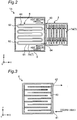
- FIG. 2 shows a schematic structure of the heating unit 3 and the heat transfer pipe 6 of the thermoelectric power generation device 1A.
- the heat transfer pipe 6 is structured so as to have a large contact area with the high temperature fluid flowing in the flow path 5, when viewed in the direction in which the high temperature fluid flows, i.e., the Y direction.
- the heat transfer pipe 6 has a plurality of tubular members 61 extending in the X direction and a plurality of bent portions 62 connecting the tubular members 61 to each other, as viewed from the Y direction.
- the plurality of tubular members 61 are arranged with a predetermined interval in the Z direction and their end portions are connected through the bent portions 62, when viewed in the Y direction. With the plurality of tubular members 61 connected through the bent portions 62 as described, the heat transfer pipe 6 forms a continuous pipe having a plurality of bent portions.
- a heat medium passage in which the heat medium flows is formed in the internal space 7a of the heating unit 3.
- the heat medium passage is formed so that the heat medium spreads throughout the entire heating surface of the thermoelectric element 2.
- a plurality of heat medium passages extending in the Z direction are formed in the internal space 7a of the heating unit 3.
- the heat medium passages in the internal space 7a of the heating unit 3 may be, for example, inclined towards the X direction, as long as the heat medium flows in the direction of gravity.
- the circulation path 7 is formed through the internal space 7a of the heating unit 3 and the internal space 7b of the heat transfer pipe 6.
- the heat medium circulates in the internal space 7a of the heating unit 3 and the internal space 7b of the heat transfer pipe 6. Specifically, when the heat transfer pipe 6 is heated by the high temperature fluid flowing in the flow path 5, the liquid heat medium flowing in the heat transfer pipe 6 is turned into vapor. In other words, the heat medium is vaporized in the internal space 7b of the heat transfer pipe 6 and the phase of the heat medium changes from liquid to gas. The vapor is discharged from an opening end portion 63 in a high position of the heat transfer pipe 6 to the heat medium passage in the internal space 7a of the heating unit 3.
- the vapor discharged into the heat medium passage in the internal space 7a of the heating unit 3 falls in the direction of gravity while being poured onto the heating surface of the heating unit 3, and is condensed by radiating heat from the heating surface to heat the thermoelectric elements 2.
- the phase of the heat medium changes from gas to liquid in the internal space 7a of the heating unit 3. That is, the heat medium undergoes latent heat transfer, and the condensation temperature of the heat medium is constant.
- the heat medium condensed flows from an open end portion 64 in a low position of the heat transfer pipe 6 into the heat medium passage in the internal space 7b of the heat transfer pipe 6.
- the heat medium having flowed into the internal space 7b of the heat transfer pipe 6 is again heated by the high temperature fluid flowing into the flow path 5, and the phase of the heat medium is changed from liquid to gas.
- the heat medium spontaneously circulates in the circulation path 7 formed by the internal space 7a of the heating unit 3 and the internal space 7b of the heat transfer pipe 6.
- the heat medium is repeatedly circulated in the circulation path 7 formed by the internal space 7a of the heating unit 3 and the internal space 7b of the heat transfer pipe 6, without power of a pump and the like.
- the cooling units 4 are each made of a metal material with excellent thermal conductivity.
- the cooling units 4 are formed in a plate shape, which contact the second sides of the thermoelectric elements 2. Further, inside each of the cooling units 4, a cooling liquid passage in which a cooling liquid flows is formed.
- FIG. 3 shows a schematic structure of the cooling unit 4 of the thermoelectric power generation device 1A.
- a plate-shape cooling liquid passage 40 is formed in such a manner that the cooling liquid is spread throughout the entire cooling surface of the cooling unit 4 which contacts the thermoelectric element 2.
- the cooling liquid passage 40 has a plurality of passages extending in the X direction, which are connected with one another.
- the cooling liquid passage 40 is provided with a cooling liquid inflow pipe 41 on its low side, and a cooling liquid discharge pipe 42 on its high side.
- the cooling liquid having flowed from the cooling liquid inflow pipe 41 into the cooling liquid passage 40 cools the cooling surface in contact with the second side of the thermoelectric element 2, and then discharged from the cooling liquid discharge pipe 42.
- the cooling liquid passage 40 in Embodiment 1 is formed in a plate shape such that the cooling liquid spreads throughout the entire cooling surface in contact with the thermoelectric element 2, the shape of the cooling liquid passage 40 is not limited as long as the second side of the thermoelectric element 2 is entirely and evenly cooled. Further, the plurality of passages of the cooling liquid passage 40 inside the cooling unit 4 may extend not only in the X direction but also in the Z direction. In Embodiment 1, water is used as the cooling liquid.
- FIG. 5 is a schematic diagram of an electric system of a thermoelectric power generation system 10.
- the thermoelectric power generation system 10A includes: four thermoelectric power generation devices 1, an inverter 11, and an electric load 12.
- the four thermoelectric power generation devices 1A are connected in parallel.
- the four thermoelectric power generation devices 1A connected in parallel are connected to the inverter 11.
- the inverter 11 is connected to the electric load 12.
- power generated by the four thermoelectric power generation devices 1A is supplied to the electric load 12 through the inverter 11.
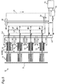
- FIG. 6 is a schematic diagram of a heat medium system of a thermoelectric power generation system 10.
- the dotted line and the one dot chain line indicate the line of the heat medium
- the solid line indicates the line of the cooling liquid.
- the heat medium line L1 is a line for filling water to become the heat medium.
- the valve of the heat medium line L1 is opened to supply the heat medium from a tank 13 into the heating unit 3, through the heat medium line L1.
- the heat medium line L2 is a line for evacuation using a vacuum pump 14. Evacuation is performed by using the vacuum pump 14 through the heat medium line L2, while the heating unit 3 has no heat medium. After the evacuation, the heat medium in the tank 13 is supplied inside the heating unit 3 through the heat medium line L1.
- the heat medium line L3 is a line for discharging the heat medium inside the heating unit 3 to the tank 13.
- the pressure valve opens and the vapor inside the heating unit 3 is discharged to the heat medium line L3.
- the heat medium discharged from the heating unit 3 flows in the heat medium line L3, and is discharged to the tank 13 through a heat exchanger 15. Since water is used as the heat medium and as the cooling liquid in Embodiment 1, the cooling liquid and the heat medium can be stored in the tank 13.
- the cooling liquid flows from the tank 13 to the cooling unit 4 through a cooling liquid line L4, with the use of a pump and the like.
- the cooling liquid having flowed into the cooling unit 4 flows to a cooling installation 16 through a cooling liquid line L5.
- the cooling installation 16 is, for example, a cooling tower for cooling the cooling liquid.
- the cooling liquid cooled in the cooling installation 16 is stored in the tank 13.
- thermoelectric power generation device 1A Next, a structure for detecting an abnormality in the thermoelectric power generation device 1A is described.
- FIG. 6 shows an abnormality detection structure of the thermoelectric power generation device 1A.
- the thermoelectric power generation device 1A includes a power generation output detection unit 21A, a heat medium pressure detection unit 22A, a storage unit 23A, and an abnormality detection unit 24A.
- the power generation output detection unit 21A detects the power generation output of the thermoelectric element 2.
- the "power generation output” is an output of the thermoelectric element 2 associated with power generation, such as voltage, current, potential, power generation amount, and the like.
- the power generation output detection unit 21A is, for example, a voltmeter, an ammeter, an electrometer, and a power generation amount meter.
- the heat medium pressure detection unit 22A detects the pressure of the heat medium flowing in the heat medium passage of the heating unit 3.
- the heat medium pressure detection unit 22A is, for example, a pressure sensor.
- the storage unit 23A stores, in advance, a relationship (e.g., a relational expression or a map) between the power generation output of the thermoelectric element 2 and the pressure of the heat medium, while the thermoelectric power generation device 1A is in a normal state.
- the "normal state” refers to a state free of an abnormality such as a failure in any of the various components of the thermoelectric power generation device 1A, leakage of cooling liquid, and the like.
- the power generation output of a thermoelectric power generation device 1A drops due to aging and the like, even if the pressure of the heat medium is the same.
- the "normal state” is preferably set in consideration of the drop in the power generation output attributed to aging and the like.
- the abnormality detection unit 24A detects that an abnormality is taking place in the thermoelectric power generation device 1A, when a relationship between the power generation output detected by the power generation output detection unit 21A and the pressure detected by the heat medium pressure detection unit 22A is different from the relationship stored in the storage unit 23A. For example, the abnormality detection unit 24A obtains the relationship (detected state) between the power generation output detected by the power generation output detection unit 21A and the pressure detected by the heat medium pressure detection unit 22A. As shown in FIG. 7 , the abnormality detection unit 24A detects that an abnormality is taking place in the thermoelectric power generation device 1A, when the detected state obtained is different from the relationship stored in the storage unit 23A, i.e., when the detected state is outside of the range of the normal state.
- the abnormality detection unit 24A detects that an abnormality is taking place in the thermoelectric power generation device 1A, if the pressure detected by the heat medium pressure detection unit 22A is 1.2MPa and the power generation output detected by the power generation output sensing part 21A is 150W.
- the abnormality detection unit 24A When the abnormality in the thermoelectric power generation device 1A is detected, the abnormality detection unit 24A notifies the user of the abnormality, for example, by means of alarming in the form of sound and display. This way, the abnormality in the thermoelectric power generation device 1A can be recognized by the user.
- thermoelectric power generation device 1A related to Embodiment 1 brings about the following effects.
- the thermoelectric power generation device 1A is configured to detect an abnormality in the thermoelectric power generation device 1A, based on whether or not the relationship between the power generation output of the thermoelectric element 2 and the pressure of the heat medium is in the normal state. With this structure, an abnormality in the thermoelectric power generation device 1A can be more reliably detected even in cases of utilizing a heat medium that undergoes latent heat transfer, in the heating unit 3.
- Embodiment 1 deals with a thermoelectric power generation system 10 having four thermoelectric power generation devices 1A; however, the present invention is not limited to this, as long as the thermoelectric power generation system 10 includes at least one thermoelectric power generation device 1A.
- Embodiment 1 adopts water as the heat medium and the cooling liquid
- the heat medium and the cooling liquid may be different. Any heat medium may be adopted provided that the heat medium can change its phase between gas and liquid in the circulation path 7. Any given liquid may be adopted as a cooling liquid, provided that cooling is possible.
- Embodiment 1 deals with a case where the thermoelectric element 2 is provided to one side of the heating unit 3, the present invention is not limited to this.
- the thermoelectric element 2 may be provided on a surface of only one side of the heating unit 3.
- the thermoelectric power generation device 1A may be configured to detect an abnormality in the thermoelectric power generation device 1A, based on whether or not the relationship between the power generation output of the thermoelectric element 2 and the temperature of the heat medium is in the normal state.
- a heat medium temperature detection unit configured to detect the temperature of the heat medium may be provided instead of the heat medium pressure detection unit 22A.
- the storage unit 23A may store, in advance, a relationship between the power generation output of the thermoelectric element 2 and the temperature of the heat medium, while the thermoelectric power generation device 1A is in the normal state.
- the abnormality detection unit 24A may be configured to detect that an abnormality is taking place in the thermoelectric power generation device 1A, when the relationship between the power generation output detected by the power generation output detection unit 21A and the temperature detected by the heat medium temperature detection unit is different from the relationship stored in the storage unit 23A.
- thermoelectric power generation device related to Embodiment 2 of the present invention is described. It should be noted that Embodiment 2 mainly describes differences from Embodiment 1. In Embodiment 2, the same symbols are given to structures identical or similar to those of Embodiment 1. Further, the description of Embodiment 2 omits descriptions which overlap with that of Embodiment 1.
- FIG. 8 shows an abnormality detection structure of a thermoelectric power generation device 1B related to Embodiment 2.
- Embodiment 2 is different from Embodiment 1 in that the thermoelectric power generation device 1B detects an abnormality of the thermoelectric power generation device 1B, based on whether or not the relationship between the power generation output of the thermoelectric element 2 and the difference between the temperature of the heat medium and the temperature of the cooling liquid is in the normal state.
- thermoelectric power generation device 1B includes: a power generation output detection unit 21B, a heat medium temperature detection unit 22B, a cooling liquid temperature detecting unit 23B, a storage unit 24B, and an abnormality detection unit 25B, as an abnormality detection structure.
- the power generation output detection unit 21B detects the power generation output of the thermoelectric element 2.
- the power generation output detection unit 21B is, for example, a voltmeter, an ammeter, an electrometer, and a power generation amount meter.
- the heat medium temperature detection unit 22B detects the temperature of the heat medium flowing in the heat medium passage of the heating unit 3.
- the cooling liquid temperature detecting unit 23B detects the temperature of the cooling liquid flowing in the cooling liquid passage of the cooling unit 4. In Embodiment 2, the cooling liquid temperature detecting unit 23B detects the temperature nearby the cooling liquid inflow pipe 41 (see FIG. 3 ).
- the heat medium temperature detection unit 22B and the cooling liquid temperature detecting unit 23B are each, for example, a temperature sensor.
- the storage unit 24B stores, in advance, a relationship (e.g., a relational expression or a map) between the power generation output of the thermoelectric element 2 and a difference between the temperature of the heat medium and the temperature of the cooling liquid, while the thermoelectric power generation device 1B is in a normal state.
- a relationship e.g., a relational expression or a map
- the abnormality detection unit 25B detects that an abnormality is taking place in the thermoelectric power generation device 1B, when the relationship between the power generation output detected by the power generation output detection unit 21B and the difference between the temperature detected by the heat medium temperature detection unit 22B and the temperature detected by the cooling liquid temperature detecting unit 23B is different from the relationship stored in the storage unit 24B. For example, the abnormality detection unit 25B obtains the relationship (detected state) between the power generation output detected by the power generation output detection unit 21B and the difference between the temperature detected by the heat medium temperature detection unit 22B and the temperature detected by the cooling liquid temperature detecting unit 23B. As shown in FIG.
- the abnormality detection unit 25B detects that an abnormality is taking place in the thermoelectric power generation device 1B, when the detected state obtained is different from the relationship stored in the storage unit 24B, i.e., when the detected state is outside of the range of the normal state.
- thermoelectric power generation device 1B related to Embodiment 2 brings about the following effects.
- the thermoelectric power generation device 1B is configured to detect an abnormality in the thermoelectric power generation device 1B, based on whether or not the relationship between the power generation output of the thermoelectric element 2 and a difference between the temperature of the heat medium and the temperature of the cooling liquid is in the normal state. That is, the thermoelectric power generation device 1B is configured to more directly detect the temperature difference by the heat medium temperature detection unit 22B and the cooling liquid temperature detecting unit 23B, for the thermoelectric element 2 that generates power by utilizing the temperature difference. With this structure, an abnormality in the thermoelectric power generation device 1B can be more reliably detected even in cases of utilizing a heat medium that undergoes latent heat transfer, in the heating unit 3.
- thermoelectric power generation device related to Embodiment 3 of the present invention is described. It should be noted that Embodiment 3 mainly describes differences from Embodiment 1. In Embodiment 3, the same symbols are given to structures identical or similar to those of Embodiment 1. Further, the description of Embodiment 3 omits descriptions which overlap with that of Embodiment 1.
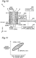
- FIG. 10 shows an abnormality detection structure of a thermoelectric power generation device 1C related to Embodiment 3.
- Embodiment 3 is different from Embodiment 1 in that the thermoelectric power generation device 1C detects an abnormality of the thermoelectric power generation device 1C, based on whether or not the relationship between the power generation output of the thermoelectric element 2 and the heat exchange amount of the cooling liquid is in the normal state.
- thermoelectric power generation device 1B includes: a power generation output detection unit 21C, a heat exchange amount detection unit 22C, a storage unit 23C, and an abnormality detection unit 24C, as an abnormality detection structure.
- the power generation output detection unit 21C detects the power generation output of the thermoelectric element 2.
- the power generation output detection unit 21C is, for example, a voltmeter, an ammeter, an electrometer, and a power generation amount meter.
- the heat exchange amount detection unit 22C detects a heat exchange amount of the cooling liquid.
- the heat exchange amount detection unit 22C detects the heat exchange amount of the cooling liquid, based on the flow rate of the cooling liquid flowing in the cooling liquid passage, the specific heat of the cooling liquid, a difference between the temperature nearby the cooling liquid discharge pipe 42 (see FIG. 3 ) and the temperature nearby the cooling liquid inflow pipe 41 (see FIG. 3 ), and the like.
- the storage unit 23C stores, in advance, a relationship (e.g., a relational expression or a map) between the power generation output of the thermoelectric element 2 and the heat exchange amount of the cooling liquid, while the thermoelectric power generation device 1C is in a normal state.
- a relationship e.g., a relational expression or a map
- the abnormality detection unit 24C detects that an abnormality is taking place in the thermoelectric power generation device 1C, when the relationship between the power generation output detected by the power generation output detection unit 21C and the heat exchange amount detected by the heat exchange amount detection unit 22C is different from the relationship stored in the storage unit 23C. For example, the abnormality detection unit 24C obtains the relationship (detected state) between the power generation output detected by the power generation output detection unit 21C and the heat exchange amount detected by the heat exchange amount detection unit 22C. As shown in FIG.
- the abnormality detection unit 24C detects that an abnormality is taking place in the thermoelectric power generation device 1C, when the detected state obtained is different from the relationship stored in the storage unit 22C, i.e., when the detected state is outside of the range of the normal state.
- thermoelectric power generation device 1C related to Embodiment 3 brings about the following effects.
- thermoelectric power generation device 1C is configured to detect an abnormality in the thermoelectric power generation device 1C, based on whether or not the relationship between the power generation output of the thermoelectric element 2 and the heat exchange amount of the cooling liquid is in the normal state. With this structure, an abnormality in the thermoelectric power generation device 1C can be more reliably detected even in cases of utilizing a heat medium that undergoes latent heat transfer, in the heating unit 3.
- Embodiment 4 mainly describes differences from Embodiment 1.
- the same symbols are given to structures identical or similar to those of Embodiment 1.
- the description of Embodiment 4 omits descriptions which overlap with that of Embodiment 1.
- FIG. 12 shows an abnormality detection structure of a thermoelectric power generation device 1D related to Embodiment 4.
- Embodiment 4 is different from Embodiment 1 in that the thermoelectric power generation device 1D detects an abnormality of the thermoelectric power generation device 1D, based on whether or not the relationship between a heat source temperature (temperature in the flow path 5 indicated in FIG. 1A ) and the pressure of the heat medium is in the normal state.
- a heat source temperature temperature in the flow path 5 indicated in FIG. 1A
- thermoelectric power generation device 1D includes: a heat source temperature detection unit 21D, a heat medium pressure detection unit 22D, a storage unit 23D, and an abnormality detection unit 24D, as an abnormality detection structure.
- the heat source temperature detection unit 21D detects the temperature in the flow path 5 (see FIG. 1A ) to serve as the heat source.
- the heat source temperature detection unit 21D is, for example, temperature sensor.
- the heat medium pressure detection unit 22D detects the pressure of the heat medium flowing in the heat medium passage of the heating unit 3.
- the heat medium pressure detection unit 22D is, for example, a pressure sensor.
- the storage unit 23D stores, in advance, a relationship (e.g., a relational expression or a map) between the heat source temperature and the pressure of the heat medium, while the thermoelectric power generation device 1D is in a normal state.
- the abnormality detection unit 24D detects that an abnormality is taking place in the thermoelectric power generation device 1C, when the relationship between the temperature detected by the heat source temperature detection unit 21D and the pressure detected by the heat medium pressure detection unit 22D is different from the relationship stored in the storage unit 23D. For example, the abnormality detection unit 24D obtains the relationship (detected state) between the temperature detected by the heat source temperature detection unit 21D and the pressure detected by the heat medium pressure detection unit 22D. As shown in FIG. 13 , the abnormality detection unit 24D detects that an abnormality is taking place in the thermoelectric power generation device 1D, when the detected state obtained is different from the relationship stored in the storage unit 23D, i.e., when the detected state is outside of the range of the normal state.
- thermoelectric power generation device 1D related to Embodiment 4 brings about the following effects.
- thermoelectric power generation device 1D is configured to detect an abnormality in the thermoelectric power generation device 1D, based on whether or not the relationship between the power generation output of the thermoelectric element 2 and the heat exchange amount of the cooling liquid is in the normal state.
- an abnormality in the thermoelectric power generation device 1D can be more reliably detected even in cases of utilizing a heat medium that undergoes latent heat transfer, in the heating unit 3.
- an excessive adhesion of soot to the heat transfer pipe 6 can be detected with this structure. That is, if the soot excessively adheres to the heat transfer pipe 6, the heat medium passing the heat transfer pipe 6 receives less quantity of heat from the heat source, which causes an excessive drop of the pressure of the heat medium.
- thermoelectric element 2 may be slightly different in each thermoelectric power generation device 1D, due to individual difference of the thermoelectric power generation device 1D.
- the heat source temperature and the pressure of the heat medium on the other hand are not influenced by the individual difference of the thermoelectric power generation device 1D. Therefore, the above structure can eliminate the need for taking into account the individual difference of the thermoelectric power generation device 1D.
- Embodiment 5 mainly describes differences from Embodiment 1.
- the same symbols are given to structures identical or similar to those of Embodiment 1.
- the description of Embodiment 5 omits descriptions which overlap with that of Embodiment 1.
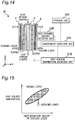
- FIG. 14 shows an abnormality detection structure of a thermoelectric power generation device 1E related to Embodiment 5.
- Embodiment 5 is different from Embodiment 1 in that the thermoelectric power generation device 1E detects an abnormality of the thermoelectric power generation device 1E, based on whether or not the relationship between a heat source temperature (temperature in the flow path 5 indicated in FIG. 1A ) and the heat exchange amount of the cooling liquid is in the normal state.
- a heat source temperature temperature in the flow path 5 indicated in FIG. 1A
- thermoelectric power generation device 1E includes: a heat source temperature detection unit 21E, a heat exchange amount detection unit 22E, a storage unit 23E, and an abnormality detection unit 24E, as an abnormality detection structure.
- the heat source temperature detection unit 21E detects the temperature in the flow path 5 (see FIG. 1A ) to serve as the heat source.
- the heat source temperature detection unit 21E is, for example, temperature sensor.
- the heat exchange amount detection unit 22E detects a heat exchange amount of the cooling liquid.
- the heat exchange amount detection unit 22E detects the heat exchange amount of the cooling liquid, based on the flow rate of the cooling liquid flowing in the cooling liquid passage, the specific heat of the cooling liquid, a difference between the temperature nearby the cooling liquid discharge pipe 42 (see FIG. 3 ) and the temperature nearby the cooling liquid inflow pipe 41 (see FIG. 3 ), and the like.
- the storage unit 23E stores, in advance, a relationship (e.g., a relational expression or a map) between the heat source temperature and the heat exchange amount of the cooling liquid, while the thermoelectric power generation device 1E is in a normal state.
- the abnormality detection unit 24E detects that an abnormality is taking place in the thermoelectric power generation device 1E, when the relationship between the heat source temperature detected by the heat source temperature detection unit 21E and the heat exchange amount detected by the heat exchange amount detection unit 22E is different from the relationship stored in the storage unit 23E. For example, the abnormality detection unit 24E obtains the relationship (detected state) between the temperature detected by the heat source temperature detection unit 21E and the heat exchange amount detected by the heat exchange amount detection unit 22E. As shown in FIG.
- the abnormality detection unit 24E detects that an abnormality is taking place in the thermoelectric power generation device 1E, when the detected state obtained is different from the relationship stored in the storage unit 23E, i.e., when the detected state is outside of the range of the normal state.
- thermoelectric power generation device 1E related to Embodiment 5 brings about the following effects.
- thermoelectric power generation device 1E is configured to detect an abnormality in the thermoelectric power generation device 1E, based on whether or not the relationship between the heat source temperature and the heat exchange amount of the cooling liquid is in the normal state.
- an abnormality in the thermoelectric power generation device 1E can be more reliably detected even in cases of utilizing a heat medium that undergoes latent heat transfer, in the heating unit 3.
- an excessive adhesion of soot to the heat transfer pipe 6 can be detected with this structure. That is, if the soot excessively adheres to the heat transfer pipe 6, the heat medium passing the heat transfer pipe 6 receives less quantity of heat from the heat source. As a result, the temperature difference between both sides of the thermoelectric element 2 decreases, and the heat exchange amount of the cooling liquid excessively drops.
- thermoelectric element 2 may be slightly different in each thermoelectric power generation device 1E, due to individual difference of the thermoelectric power generation device 1E.
- the heat source temperature and the heat exchange amount of the cooling liquid on the other hand are not influenced by the individual difference of the thermoelectric power generation device 1E. Therefore, the above structure can eliminate the need for taking into account the individual difference of the thermoelectric power generation device 1E.
- thermoelectric power generation device related to Embodiment 6 of the present invention is described. It should be noted that Embodiment 6 mainly describes differences from Embodiment 1. In Embodiment 6, the same symbols are given to structures identical or similar to those of Embodiment 1. Further, the description of Embodiment 6 omits descriptions which overlap with that of Embodiment 1.
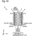
- FIG. 16 shows an abnormality detection structure of a thermoelectric power generation device 1F related to Embodiment 6.
- Embodiment 6 is different from Embodiment 1 in that the thermoelectric power generation device 1F detects an abnormality of the thermoelectric power generation device 1F, based on a difference between the power generation outputs from a pair of thermoelectric elements 2 (20a, 20b).
- the thermoelectric power generation device 1F includes, as an abnormality detection structure, an abnormality detection unit 21F configured to detect that an abnormality is taking place in the thermoelectric power generation device 1F, when the difference between a power generation output of one of the pair of thermoelectric elements 2 and a power generation output of the other one of the pair of thermoelectric elements 2 is equal to or higher than a predetermined threshold value.
- the abnormality detection unit 21F includes, for example, a voltmeter, an ammeter, an electrometer, and a power generation amount meter.
- thermoelectric power generation device 1F related to Embodiment 6 brings about the following effects.
- thermoelectric power generation device 1F is configured to detect that an abnormality is taking place in the thermoelectric power generation device 1F, when the difference between the power generation outputs of the pair of the thermoelectric elements 2 is greater than an expectable error (predetermined threshold value).
- an abnormality in the thermoelectric power generation device 1F can be more reliably detected even in cases of utilizing a heat medium that undergoes latent heat transfer, in the heating unit 3. Further, in which one of the pair of thermoelectric elements 2 the abnormality is taking place can be recognized.
- the above structure does not require a heat medium pressure detection unit, a storage unit, and the like, because it only compares the power generation outputs of the pair of the thermoelectric elements 2.
- Embodiment 7 mainly describes differences from Embodiment 1.
- the same symbols are given to structures identical or similar to those of Embodiment 1.
- the description of Embodiment 7 omits descriptions which overlap with that of Embodiment 1.
- FIG. 17 shows an abnormality detection structure of a thermoelectric power generation device 1G related to Embodiment 7.
- Embodiment 7 is different from Embodiment 1 in that the thermoelectric power generation device 1G detects an abnormality of the thermoelectric power generation device 1G, based on the pressure of the heat medium.
- thermoelectric power generation device 1G includes: a heat medium pressure detection unit 21G and an abnormality detection unit 22G, as an abnormality detection structure.
- the heat medium pressure detection unit 21G detects the pressure of the heat medium flowing in the heat medium passage of the heating unit 3.
- the heat medium pressure detection unit 21G is, for example, a pressure sensor.
- the abnormality detection unit 22G detects that an abnormality is taking place in the thermoelectric power generation device 1G, when a converted saturation temperature based on the pressure detected by the heat medium pressure detection unit 21G exceeds a predetermined threshold value. For example, where the predetermined threshold value is 200 degrees, and the pressure detected by the heat medium pressure detection unit 21G is 1.6Mpa, and the converted saturation temperature of the heat medium based on the pressure is 210 degrees, the abnormality detection unit 22G detects that an abnormality is taking place in the thermoelectric power generation device 1G.
- thermoelectric power generation device 1G related to Embodiment 7 brings about the following effects.
- the thermoelectric element 2 may be overheated and may fail due to the heat.
- the temperature of the heat medium flowing in the heat medium passage can be easily detected by letting the heat medium to partially flow into a branch pipe connected to the heat medium passage, and detecting the temperature of the part of the heat medium. In this case however, the heat medium may be cooled in the process of passing the branch pipe, and the temperature of the heat medium may not be accurately detected.
- the pressure of the heat medium is the same whether it is in the heat medium passage or in the branch pipe. Further, as hereinabove described, the pressure of the heat medium is proportional to the temperature of the heat medium.
- thermoelectric power generation device 1G is configured to detect an abnormality in the thermoelectric power generation device 1G based on the pressure of the heat medium.
- an abnormality (overheating) in the thermoelectric power generation device 1G can be more reliably detected even in cases of utilizing a heat medium that undergoes latent heat transfer, in the heating unit 3.
- the present invention can more reliably detect an abnormality, the present invention is useful for a thermoelectric power generation device which generates power by utilizing the heat of a high temperature fluid flowing in an exhaust gas duct and the like of an engine.
Landscapes
- Measuring Volume Flow (AREA)
- Engine Equipment That Uses Special Cycles (AREA)
- Investigating Or Analyzing Materials Using Thermal Means (AREA)
Abstract
Description
- The present invention relates to a thermoelectric power generation device which generates power by utilizing a temperature difference.
- An example of such a type of traditional thermoelectric power generation device is disclosed in Patent Literature 1 (hereinafter referred to as PTL 1).
PTL 1 discloses a thermoelectric power generation device including a heating unit having a heat medium passage on one surface of a thermoelectric element and a cooling unit having a coolant passage on the other surface of the thermoelectric element, the device being configured to generate power by utilizing a temperature difference between a heat medium flowing in the heat medium passage and a coolant flowing in the coolant passage. - Further, Patent Literature 2 (hereinafter, referred to as PTL 2) discloses a structure for detecting an abnormality in a thermoelectric power generation device mounted in a vehicle, based on an estimated power generation amount corresponding to an engine speed or the speed of the vehicle, and an actual power generation amount.
-
- PTL 1: Japanese Patent Application Laid-Open No.
2015-012173 - PTL 2: Japanese Patent Application Laid-Open No.
2007-014161 - In a traditional thermoelectric power generation device such as the one disclosed in
PTL 1 andPTL 2, a high-temperature liquid or gas is supplied as a heat medium into a heat medium passage. In such a structure, the heat medium flowing in the heat medium passage is in the same phase, and therefore the heat medium undergoes sensible heat transfer. In other words, the temperature changes while the heat medium flows in the heat medium passage. - Meanwhile, the inventors of the present invention have found that, by causing a phase transition of the heat medium (e.g. from gas to liquid) while the heat medium flows in the heat medium passage, the temperature of the heat medium can be constant and the power generation amount can be improved. In other words, during the latent heat transfer of the heat medium, the condensation temperature of the heat medium is constant, and by utilizing this, the inventors of the present invention have found that the power generation amount can be improved.
- Meanwhile, a thermoelectric power generation device is expected to be used for a long period of time of approximately several years to several tens of years. During this long-term usage, the power generation output may abnormally be lowered, due to a failure of any of the parts of the thermoelectric power generation device, leakage of the cooling liquid, and the like. For this reason, a thermoelectric power generation device preferably has a structure for detecting an abnormality as described in
PTL 2. - However,
PTL 2 premises use of a heat medium that undergoes sensible heat transfer, and does not assume the use of a heat medium that undergoes latent heat transfer. Therefore, a traditional thermoelectric power generation device still leaves a room for improvement in terms of more reliable detection of an abnormality in the thermoelectric power generation device. - To achieve the above problem, the present invention is made, and it is an object of the present invention to provide a thermoelectric power generation device that can more reliably detect an abnormality in the thermoelectric power generation device.
- A thermoelectric power generation device related to an aspect of the present invention includes:
- a heating unit having a heat medium passage in which a heat medium flows;
- a cooling unit having a cooling liquid passage in which a cooling liquid flows; and
- a thermoelectric element having the heating unit on one side and the cooling unit on another side, the thermoelectric element configured to generate power by utilizing a temperature difference between a condensation temperature of the heat medium that undergoes latent heat transfer in the heat medium passage and a temperature of the cooling liquid, the thermoelectric power generation device further including
- a power generation output detection unit configured to detect a power generation output of the thermoelectric element;
- a heat medium pressure detection unit configured to detect a pressure of the heat medium or a heat medium temperature detection unit configured to detect a temperature of the heat medium;
- a storage unit for storing, in advance, a relationship between a power generation output of the thermoelectric element and the pressure or the temperature of the heat medium, when the thermoelectric power generation device is in a normal state; and
- an abnormality detection unit configured to detect that an abnormality is taking place in the thermoelectric power generation device, when a relationship between the power generation output detected by the power generation output detection unit and the pressure detected by the heat medium pressure detection unit or the temperature detected by the heat medium temperature detection unit is different from the relationship stored in the storage unit.
- Further, a thermoelectric power generation device related to another aspect of the present invention includes:
- a heating unit having a heat medium passage in which a heat medium flows;
- a cooling unit having a cooling liquid passage in which a cooling liquid flows; and
- a thermoelectric element having the heating unit on one side and the cooling unit on another side, the thermoelectric element configured to generate power by utilizing a temperature difference between a condensation temperature of the heat medium that undergoes latent heat transfer in the heat medium passage and a temperature of the cooling liquid, the thermoelectric power generation device further including
- a power generation output detection unit configured to detect a power generation output of the thermoelectric element;
- a heat medium temperature detection unit configured to detect a temperature of the heat medium;
- a cooling liquid temperature detecting unit configured to detect a temperature of the cooling liquid;
- a storage unit for storing, in advance, a relationship between a power generation output of the thermoelectric element and a difference between the temperature of the heat medium and the temperature of the cooling liquid, when the thermoelectric power generation device is in a normal state; and
- an abnormality detection unit configured to detect that an abnormality is taking place in the thermoelectric power generation device, when a relationship between the power generation output detected by the power generation output detection unit and the difference between the temperature detected by the heat medium temperature detection unit and the temperature detected by the cooling liquid temperature detecting unit is different from the relationship stored in the storage unit.
- Further, a thermoelectric power generation device related to another aspect of the present invention includes: a heating unit having a heat medium passage in which a heat medium flows;
a cooling unit having a cooling liquid passage in which a cooling liquid flows; and
a thermoelectric element having the heating unit on one side and the cooling unit on another side, the thermoelectric element configured to generate power by utilizing a temperature difference between a condensation temperature of the heat medium that undergoes latent heat transfer in the heat medium passage and a temperature of the cooling liquid,
the thermoelectric power generation device further including
a power generation output detection unit configured to detect a power generation output of the thermoelectric element;
a heat medium temperature detection unit configured to detect the temperature of the heat medium;
a heat exchange amount detection unit configured to detect a heat exchange amount of the cooling liquid;
a storage unit for storing, in advance, a relationship between a power generation output of the thermoelectric element and a heat exchange amount of the cooling liquid, when the thermoelectric power generation device is in a normal state; and
an abnormality detection unit configured to detect that an abnormality is taking place in the thermoelectric power generation device, when a relationship between the power generation output detected by the power generation output detection unit and the heat exchange amount detected by the heat exchange amount detection unit is different from the relationship stored in the storage unit. - Further, a thermoelectric power generation device related to another aspect of the present invention includes:
- a heating unit having a heat medium passage in which a heat medium flows;
- a cooling unit having a cooling liquid passage in which a cooling liquid flows;
- a thermoelectric element having the heating unit on one side and the cooling unit on another side, the thermoelectric element configured to generate power by utilizing a temperature difference between a condensation temperature of the heat medium that undergoes latent heat transfer in the heat medium passage and a temperature of the cooling liquid; and
- a heat transfer pipe arranged in a flow path to serve as a heat source, and communicated with the heat medium passage to form a circulation path in which the heat medium is circulated, the thermoelectric power generation device further including
- a heat source temperature detection unit configured to detect a heat source temperature;
- a heat medium pressure detection unit configured to detect a pressure of the heat medium or a heat medium temperature detection unit configured to detect a temperature of the heat medium;
- a storage unit for storing, in advance, a relationship between the heat source temperature and the pressure or the temperature of the heat medium, when the thermoelectric power generation device is in a normal state; and
- an abnormality detection unit configured to detect that an abnormality is taking place in the thermoelectric power generation device, when a relationship between the temperature detected by the heat source temperature detection unit and the pressure detected by the heat medium pressure detection unit or the temperature detected by the heat medium temperature detection unit is different from the relationship stored in the storage unit.
- Further, a thermoelectric power generation device related to another aspect of the present invention includes:
- a heating unit having a heat medium passage in which a heat medium flows;
- a cooling unit having a cooling liquid passage in which a cooling liquid flows;
- a thermoelectric element having the heating unit on one side and the cooling unit on another side, the thermoelectric element configured to generate power by utilizing a temperature difference between a condensation temperature of the heat medium that undergoes latent heat transfer in the heat medium passage and a temperature of the cooling liquid; and
- a heat transfer pipe arranged in a flow path to serve as a heat source, and communicated with the heat medium passage to form a circulation path in which the heat medium is circulated, the thermoelectric power generation device further including
- a heat source temperature detection unit configured to detect a heat source temperature;
- a heat exchange amount detection unit configured to detect a heat exchange amount of the cooling liquid;
- a storage unit for storing, in advance, a relationship between the heat source temperature and the heat exchange amount, when the thermoelectric power generation device is in a normal state; and
- an abnormality detection unit configured to detect that an abnormality is taking place in the thermoelectric power generation device, when a relationship between the temperature detected by the heat source temperature detection unit and the heat exchange amount detected by the heat exchange amount detection unit is different from the relationship stored in the storage unit.
- Further, a thermoelectric power generation device related to another aspect of the present invention includes:
- a heating unit having a heat medium passage in which a heat medium flows;
- a pair of cooling units each having a cooling liquid passage in which a cooling liquid flows; and
- a pair of thermoelectric elements each having the heating unit on one side and one of the pair of cooling units on another side, the thermoelectric element configured to generate power by utilizing a temperature difference between a condensation temperature of the heat medium that undergoes latent heat transfer in the heat medium passage and a temperature of the cooling liquid, wherein
- the pair of thermoelectric elements are arranged to face each other over the heating unit;
- the pair of cooling units are arranged to face each other over the heating unit and the pair of thermoelectric elements; and
- the thermoelectric power generation device further includes an abnormality detection unit configured to detect that an abnormality is taking place in the thermoelectric power generation device, when a difference between a power generation output of one of the pair of thermoelectric elements and a power generation output of the other one of the pair of thermoelectric elements is equal to or higher than a predetermined threshold value.
- With the thermoelectric power generation device of the present invention, an abnormality in the thermoelectric power generation device can be more reliably detected.
-
- [
FIG. 1A ] A diagram showing a schematic structure of a thermoelectric power generation device related toEmbodiment 1 of the present invention. - [
FIG. 1B ] A diagram showing a schematic structure of the thermoelectric power generation device related toEmbodiment 1 of the present invention as viewed from behind. - [
FIG. 2 ] A diagram showing a schematic structure of a heating unit of the thermoelectric power generation device related toEmbodiment 1 of the present invention. - [
FIG. 3 ] A diagram showing a schematic structure of a cooling unit of the thermoelectric power generation device related toEmbodiment 1 of the present invention. - [
FIG. 4 ] A schematic diagram of an electric system of a thermoelectric power generation system using the thermoelectric power generation device related toEmbodiment 1 of the present invention. - [
FIG. 5 ] A schematic diagram of a heat medium system of the thermoelectric power generation system using the thermoelectric power generation device related toEmbodiment 1 of the present invention. - [
FIG. 6 ] A diagram showing an abnormality detection structure of a thermoelectric power generation device related toEmbodiment 1 of the present invention. - [
FIG. 7 ] A graph showing a relationship between the power generation output of the thermoelectric element and the pressure (or temperature) of the heat medium, in the normal state and the detected state. - [
FIG. 8 ] A diagram showing an abnormality detection structure of a thermoelectric power generation device related toEmbodiment 2 of the present invention. - [
FIG. 9 ] A graph showing a relationship between the power generation output of the thermoelectric element and a difference between the temperature of a heat medium and the temperature of a cooling liquid, in the normal state and the detected state. - [
FIG. 10 ] A diagram showing an abnormality detection structure of a thermoelectric power generation device related toEmbodiment 3 of the present invention. - [
FIG. 11 ] A graph showing a relationship between the power generation output of the thermoelectric element and a heat exchange amount of a cooling liquid, in the normal state and the detected state. - [
FIG. 12 ] A diagram showing an abnormality detection structure of a thermoelectric power generation device related toEmbodiment 4 of the present invention. - [
FIG. 13 ] A graph showing a relationship between the heat source temperature and the pressure (or temperature) of the heat medium, in the normal state and the detected state. - [
FIG. 14 ] A diagram showing an abnormality detection structure of a thermoelectric power generation device related toEmbodiment 5 of the present invention. - [
FIG. 15 ] A graph showing a relationship between the heat source temperature and a heat exchange amount of a cooling liquid, in the normal state and the detected state. - [
FIG. 16 ] A diagram showing an abnormality detection structure of a thermoelectric power generation device related toEmbodiment 6 of the present invention. - [
FIG. 17 ] A diagram showing an abnormality detection structure of a thermoelectric power generation device related toEmbodiment 7 of the present invention. - The following describes embodiments with reference to attached drawings. In each of the drawings, elements are exaggerated for the sake of easier understanding.
- A basic structure of a thermoelectric power generation device related to
Embodiment 1 is described. -
FIG. 1A shows a schematic structure of a thermoelectricpower generation device 1 related toEmbodiment 1. The directions X, Y, and Z inFIG. 1A indicate the longitudinal direction, lateral direction, and the height direction of the thermoelectricpower generation device 1A, respectively. The longitudinal direction, the lateral direction, and the height direction mean the length direction, short direction, and the up-down direction of the thermoelectricpower generation device 1A, respectively.FIG. 1B is a diagram showing a schematic structure of the thermoelectricpower generation device 1A as viewed from behind (in X direction). - As shown in
FIG. 1A and FIG. 1B , the thermoelectricpower generation device 1A includes athermoelectric element 2 in which aheating unit 3 is provided on one surface and acooling unit 4 is provided on the other surface. InEmbodiment 1, thethermoelectric elements 2 are provided on both sides of theheating unit 3, and thecooling units 4 are provided on both sides of theheating unit 3 so as to face each other across thethermoelectric elements 2. That is, the thermoelectricpower generation device 1A includes a pair ofthermoelectric elements 2 arranged to face each other over theheating unit 3, and a pair ofcooling units 4 arranged to face each other over theheating unit 3 and the pair ofthermoelectric element 2. Further, inEmbodiment 1, theheating unit 3 is connected to aheat transfer pipe 6 arranged in aflow path 5 in which a high temperature fluid flows. - The
thermoelectric element 2 is an element having two surfaces, i.e., one surface on which theheating unit 3 is provided (the high-temperature side) and the other surface on which thecooling unit 4 is provided (on the low-temperature side). In thethermoelectric element 2, theheating unit 3 heats the one surface and thecooling unit 4 cools the other surface, thereby generating power using the temperature difference. The thickness of thethermoelectric element 2 is designed to be smaller than the size (width) of the first side and the second side of thethermoelectric element 2. Specifically, thethermoelectric element 2 is formed in a plate shape. InEmbodiment 1,thermoelectric modules thermoelectric elements 2 are attached to both sides of theheating unit 3. Specifically, on both sides of theheating unit 3, thethermoelectric modules thermoelectric elements 2 of four columns x five rows are attached. The number ofthermoelectric elements 2 is not limited to this. For example, the thermoelectricpower generation device 1A may have onethermoelectric element 2 attached to each of both sides of theheating unit 3. - The
heating unit 3 is made of a metal material with excellent thermal conductivity. Theheating unit 3 is formed in a plate shape, which contacts first sides of thethermoelectric elements 2. Theheating unit 3 is connected to theheat transfer pipe 6. Theheating unit 3 and theheat transfer pipe 6 haveinternal spaces internal space 7a of theheating unit 3 and theinternal space 7b of theheat transfer pipe 6, a heat medium is enclosed. Further, theinternal space 7a of theheating unit 3 and theinternal space 7b of theheat transfer pipe 6 form acirculation path 7 in which the heat medium is circulated. That is, theheat transfer pipe 6 communicates with the heat medium passage to form acirculation path 7 in which heat medium is circulated. - The
heat transfer pipe 6 is arranged in theflow path 5 to serve as a heat source and vaporizes the heat medium flowing in theinternal space 7b which is a part of thecirculation path 7, by using the heat of the high temperature fluid flowing in theflow path 5. That is, theheat transfer pipe 6 functions as a vaporizing unit for vaporizing the heat medium. Theheating unit 3 condenses the heat medium vaporized in theinternal space 7b of theheat transfer pipe 6. That is, theheating unit 3 functions as a condensing unit for condensing the heat medium. InEmbodiment 1, water is used as the heat medium. Further, theflow path 5 is, for example, an engine duct of exhaust gas through which a high-temperature exhaust gas flows. In theflow path 5, the high temperature fluid flows in a direction towards the paper surface ofFIG. 1A , i.e., in the Y direction. Theflow path 5 may be, for example, a high-temperature environment such as an industrial waste furnace or a biomass boiler, or a radiation field not requiring convection, in addition to the exhaust gas duct of an engine. -
FIG. 2 shows a schematic structure of theheating unit 3 and theheat transfer pipe 6 of the thermoelectricpower generation device 1A. As shown inFIG. 2 , theheat transfer pipe 6 is structured so as to have a large contact area with the high temperature fluid flowing in theflow path 5, when viewed in the direction in which the high temperature fluid flows, i.e., the Y direction. Specifically, theheat transfer pipe 6 has a plurality oftubular members 61 extending in the X direction and a plurality ofbent portions 62 connecting thetubular members 61 to each other, as viewed from the Y direction. The plurality oftubular members 61 are arranged with a predetermined interval in the Z direction and their end portions are connected through thebent portions 62, when viewed in the Y direction. With the plurality oftubular members 61 connected through thebent portions 62 as described, theheat transfer pipe 6 forms a continuous pipe having a plurality of bent portions. - In the
internal space 7a of theheating unit 3, a heat medium passage in which the heat medium flows is formed. InEmbodiment 1, the heat medium passage is formed so that the heat medium spreads throughout the entire heating surface of thethermoelectric element 2. Specifically, as shown inFIG. 2 , a plurality of heat medium passages extending in the Z direction are formed in theinternal space 7a of theheating unit 3. The heat medium passages in theinternal space 7a of theheating unit 3 may be, for example, inclined towards the X direction, as long as the heat medium flows in the direction of gravity. - The
circulation path 7 is formed through theinternal space 7a of theheating unit 3 and theinternal space 7b of theheat transfer pipe 6. The heat medium circulates in theinternal space 7a of theheating unit 3 and theinternal space 7b of theheat transfer pipe 6. Specifically, when theheat transfer pipe 6 is heated by the high temperature fluid flowing in theflow path 5, the liquid heat medium flowing in theheat transfer pipe 6 is turned into vapor. In other words, the heat medium is vaporized in theinternal space 7b of theheat transfer pipe 6 and the phase of the heat medium changes from liquid to gas. The vapor is discharged from an openingend portion 63 in a high position of theheat transfer pipe 6 to the heat medium passage in theinternal space 7a of theheating unit 3. The vapor discharged into the heat medium passage in theinternal space 7a of theheating unit 3 falls in the direction of gravity while being poured onto the heating surface of theheating unit 3, and is condensed by radiating heat from the heating surface to heat thethermoelectric elements 2. In other words, the phase of the heat medium changes from gas to liquid in theinternal space 7a of theheating unit 3. That is, the heat medium undergoes latent heat transfer, and the condensation temperature of the heat medium is constant. The heat medium condensed flows from anopen end portion 64 in a low position of theheat transfer pipe 6 into the heat medium passage in theinternal space 7b of theheat transfer pipe 6. The heat medium having flowed into theinternal space 7b of theheat transfer pipe 6 is again heated by the high temperature fluid flowing into theflow path 5, and the phase of the heat medium is changed from liquid to gas. As described, the heat medium spontaneously circulates in thecirculation path 7 formed by theinternal space 7a of theheating unit 3 and theinternal space 7b of theheat transfer pipe 6. In other words, by using the phase change of the heat medium, the heat medium is repeatedly circulated in thecirculation path 7 formed by theinternal space 7a of theheating unit 3 and theinternal space 7b of theheat transfer pipe 6, without power of a pump and the like. - The cooling
units 4 are each made of a metal material with excellent thermal conductivity. The coolingunits 4 are formed in a plate shape, which contact the second sides of thethermoelectric elements 2. Further, inside each of thecooling units 4, a cooling liquid passage in which a cooling liquid flows is formed. -
FIG. 3 shows a schematic structure of thecooling unit 4 of the thermoelectricpower generation device 1A. As shown inFIG. 3 , inside thecooling unit 4, a plate-shape coolingliquid passage 40 is formed in such a manner that the cooling liquid is spread throughout the entire cooling surface of thecooling unit 4 which contacts thethermoelectric element 2. Specifically, the coolingliquid passage 40 has a plurality of passages extending in the X direction, which are connected with one another. The coolingliquid passage 40 is provided with a coolingliquid inflow pipe 41 on its low side, and a coolingliquid discharge pipe 42 on its high side. The cooling liquid having flowed from the coolingliquid inflow pipe 41 into the coolingliquid passage 40 cools the cooling surface in contact with the second side of thethermoelectric element 2, and then discharged from the coolingliquid discharge pipe 42. Although the coolingliquid passage 40 inEmbodiment 1 is formed in a plate shape such that the cooling liquid spreads throughout the entire cooling surface in contact with thethermoelectric element 2, the shape of the coolingliquid passage 40 is not limited as long as the second side of thethermoelectric element 2 is entirely and evenly cooled. Further, the plurality of passages of the coolingliquid passage 40 inside thecooling unit 4 may extend not only in the X direction but also in the Z direction. InEmbodiment 1, water is used as the cooling liquid. -
FIG. 5 is a schematic diagram of an electric system of a thermoelectricpower generation system 10. As shown inFIG. 5 , the thermoelectric power generation system 10A includes: four thermoelectricpower generation devices 1, an inverter 11, and anelectric load 12. In the thermoelectricpower generation system 10, the four thermoelectricpower generation devices 1A are connected in parallel. The four thermoelectricpower generation devices 1A connected in parallel are connected to the inverter 11. The inverter 11 is connected to theelectric load 12. In the thermoelectricpower generation system 10, power generated by the four thermoelectricpower generation devices 1A is supplied to theelectric load 12 through the inverter 11. -
FIG. 6 is a schematic diagram of a heat medium system of a thermoelectricpower generation system 10. InFIG. 6 , the dotted line and the one dot chain line indicate the line of the heat medium, and the solid line indicates the line of the cooling liquid. First, a flow of the heat medium is described. As shown inFIG. 6 , the heatmedium lines L 1,L 2, andL 3 are connected to theheating unit 3 of the thermoelectricpower generation device 1A. To the heat medium lines L1, L2, and L3, valves are provided respectively. While the heat medium spontaneously circulates inside theheating unit 3, the heat medium lines L1, L2, L3 are closed. The valve provided to the heat medium line L3 is a pressure valve. - The heat medium line L1 is a line for filling water to become the heat medium. To supply the heat medium inside the
heating unit 3, the valve of the heat medium line L1 is opened to supply the heat medium from atank 13 into theheating unit 3, through the heat medium line L1. - The heat medium line L2 is a line for evacuation using a
vacuum pump 14. Evacuation is performed by using thevacuum pump 14 through the heat medium line L2, while theheating unit 3 has no heat medium. After the evacuation, the heat medium in thetank 13 is supplied inside theheating unit 3 through the heat medium line L1. - The heat medium line L3 is a line for discharging the heat medium inside the
heating unit 3 to thetank 13. When the vapor pressure inside theheating unit 3 becomes higher than the tolerance of the pressure valve of the heat medium line L3, the pressure valve opens and the vapor inside theheating unit 3 is discharged to the heat medium line L3. The heat medium discharged from theheating unit 3 flows in the heat medium line L3, and is discharged to thetank 13 through aheat exchanger 15. Since water is used as the heat medium and as the cooling liquid inEmbodiment 1, the cooling liquid and the heat medium can be stored in thetank 13. - Next, a flow of the cooling liquid is described. As shown in
FIG. 6 , the cooling liquid flows from thetank 13 to thecooling unit 4 through a cooling liquid line L4, with the use of a pump and the like. The cooling liquid having flowed into thecooling unit 4 flows to acooling installation 16 through a cooling liquid line L5. The coolinginstallation 16 is, for example, a cooling tower for cooling the cooling liquid. The cooling liquid cooled in thecooling installation 16 is stored in thetank 13. - Next, a structure for detecting an abnormality in the thermoelectric
power generation device 1A is described. -
FIG. 6 shows an abnormality detection structure of the thermoelectricpower generation device 1A. As shown inFIG. 6 , the thermoelectricpower generation device 1A includes a power generationoutput detection unit 21A, a heat mediumpressure detection unit 22A, astorage unit 23A, and anabnormality detection unit 24A. - The power generation
output detection unit 21A detects the power generation output of thethermoelectric element 2. The "power generation output" is an output of thethermoelectric element 2 associated with power generation, such as voltage, current, potential, power generation amount, and the like. The power generationoutput detection unit 21A is, for example, a voltmeter, an ammeter, an electrometer, and a power generation amount meter. - The heat medium
pressure detection unit 22A detects the pressure of the heat medium flowing in the heat medium passage of theheating unit 3. The heat mediumpressure detection unit 22A is, for example, a pressure sensor. - The
storage unit 23A stores, in advance, a relationship (e.g., a relational expression or a map) between the power generation output of thethermoelectric element 2 and the pressure of the heat medium, while the thermoelectricpower generation device 1A is in a normal state. The "normal state" refers to a state free of an abnormality such as a failure in any of the various components of the thermoelectricpower generation device 1A, leakage of cooling liquid, and the like. Generally, the power generation output of a thermoelectricpower generation device 1A drops due to aging and the like, even if the pressure of the heat medium is the same. As shown inFIG. 7 , the "normal state" is preferably set in consideration of the drop in the power generation output attributed to aging and the like. - The
abnormality detection unit 24A detects that an abnormality is taking place in the thermoelectricpower generation device 1A, when a relationship between the power generation output detected by the power generationoutput detection unit 21A and the pressure detected by the heat mediumpressure detection unit 22A is different from the relationship stored in thestorage unit 23A. For example, theabnormality detection unit 24A obtains the relationship (detected state) between the power generation output detected by the power generationoutput detection unit 21A and the pressure detected by the heat mediumpressure detection unit 22A. As shown inFIG. 7 , theabnormality detection unit 24A detects that an abnormality is taking place in the thermoelectricpower generation device 1A, when the detected state obtained is different from the relationship stored in thestorage unit 23A, i.e., when the detected state is outside of the range of the normal state. For example, suppose that the normal state is a state when the pressure of the heat medium is 1.2MPa and the power generation output of thethermoelectric element 2 is 180W or higher but not higher than 200W. In this case, theabnormality detection unit 24A detects that an abnormality is taking place in the thermoelectricpower generation device 1A, if the pressure detected by the heat mediumpressure detection unit 22A is 1.2MPa and the power generation output detected by the power generationoutput sensing part 21A is 150W. - When the abnormality in the thermoelectric
power generation device 1A is detected, theabnormality detection unit 24A notifies the user of the abnormality, for example, by means of alarming in the form of sound and display. This way, the abnormality in the thermoelectricpower generation device 1A can be recognized by the user. - The thermoelectric
power generation device 1A related toEmbodiment 1 brings about the following effects. - The thermoelectric
power generation device 1A is configured to detect an abnormality in the thermoelectricpower generation device 1A, based on whether or not the relationship between the power generation output of thethermoelectric element 2 and the pressure of the heat medium is in the normal state. With this structure, an abnormality in the thermoelectricpower generation device 1A can be more reliably detected even in cases of utilizing a heat medium that undergoes latent heat transfer, in theheating unit 3. - It should be noted that
Embodiment 1 deals with a thermoelectricpower generation system 10 having four thermoelectricpower generation devices 1A; however, the present invention is not limited to this, as long as the thermoelectricpower generation system 10 includes at least one thermoelectricpower generation device 1A. - Although
Embodiment 1 adopts water as the heat medium and the cooling liquid, the present invention is not limited to this. The heat medium and the cooling liquid may be different. Any heat medium may be adopted provided that the heat medium can change its phase between gas and liquid in thecirculation path 7. Any given liquid may be adopted as a cooling liquid, provided that cooling is possible. - Although
Embodiment 1 deals with a case where thethermoelectric element 2 is provided to one side of theheating unit 3, the present invention is not limited to this. For example, thethermoelectric element 2 may be provided on a surface of only one side of theheating unit 3. - Since the pressure of the heat medium is proportional to the temperature of the heat medium, the thermoelectric
power generation device 1A may be configured to detect an abnormality in the thermoelectricpower generation device 1A, based on whether or not the relationship between the power generation output of thethermoelectric element 2 and the temperature of the heat medium is in the normal state. Specifically, a heat medium temperature detection unit configured to detect the temperature of the heat medium may be provided instead of the heat mediumpressure detection unit 22A. In this case, thestorage unit 23A may store, in advance, a relationship between the power generation output of thethermoelectric element 2 and the temperature of the heat medium, while the thermoelectricpower generation device 1A is in the normal state. Further, theabnormality detection unit 24A may be configured to detect that an abnormality is taking place in the thermoelectricpower generation device 1A, when the relationship between the power generation output detected by the power generationoutput detection unit 21A and the temperature detected by the heat medium temperature detection unit is different from the relationship stored in thestorage unit 23A. - A thermoelectric power generation device related to
Embodiment 2 of the present invention is described. It should be noted thatEmbodiment 2 mainly describes differences fromEmbodiment 1. InEmbodiment 2, the same symbols are given to structures identical or similar to those ofEmbodiment 1. Further, the description ofEmbodiment 2 omits descriptions which overlap with that ofEmbodiment 1. -
FIG. 8 shows an abnormality detection structure of a thermoelectricpower generation device 1B related toEmbodiment 2. -
Embodiment 2 is different fromEmbodiment 1 in that the thermoelectricpower generation device 1B detects an abnormality of the thermoelectricpower generation device 1B, based on whether or not the relationship between the power generation output of thethermoelectric element 2 and the difference between the temperature of the heat medium and the temperature of the cooling liquid is in the normal state. - Specifically, the thermoelectric
power generation device 1B includes: a power generationoutput detection unit 21B, a heat mediumtemperature detection unit 22B, a cooling liquidtemperature detecting unit 23B, astorage unit 24B, and anabnormality detection unit 25B, as an abnormality detection structure. - The power generation
output detection unit 21B detects the power generation output of thethermoelectric element 2. The power generationoutput detection unit 21B is, for example, a voltmeter, an ammeter, an electrometer, and a power generation amount meter. The heat mediumtemperature detection unit 22B detects the temperature of the heat medium flowing in the heat medium passage of theheating unit 3. The cooling liquidtemperature detecting unit 23B detects the temperature of the cooling liquid flowing in the cooling liquid passage of thecooling unit 4. InEmbodiment 2, the cooling liquidtemperature detecting unit 23B detects the temperature nearby the cooling liquid inflow pipe 41 (seeFIG. 3 ). The heat mediumtemperature detection unit 22B and the cooling liquidtemperature detecting unit 23B are each, for example, a temperature sensor. Thestorage unit 24B stores, in advance, a relationship (e.g., a relational expression or a map) between the power generation output of thethermoelectric element 2 and a difference between the temperature of the heat medium and the temperature of the cooling liquid, while the thermoelectricpower generation device 1B is in a normal state. - The
abnormality detection unit 25B detects that an abnormality is taking place in the thermoelectricpower generation device 1B, when the relationship between the power generation output detected by the power generationoutput detection unit 21B and the difference between the temperature detected by the heat mediumtemperature detection unit 22B and the temperature detected by the cooling liquidtemperature detecting unit 23B is different from the relationship stored in thestorage unit 24B. For example, theabnormality detection unit 25B obtains the relationship (detected state) between the power generation output detected by the power generationoutput detection unit 21B and the difference between the temperature detected by the heat mediumtemperature detection unit 22B and the temperature detected by the cooling liquidtemperature detecting unit 23B. As shown inFIG. 9 , theabnormality detection unit 25B detects that an abnormality is taking place in the thermoelectricpower generation device 1B, when the detected state obtained is different from the relationship stored in thestorage unit 24B, i.e., when the detected state is outside of the range of the normal state. - The thermoelectric
power generation device 1B related toEmbodiment 2 brings about the following effects. - The thermoelectric
power generation device 1B is configured to detect an abnormality in the thermoelectricpower generation device 1B, based on whether or not the relationship between the power generation output of thethermoelectric element 2 and a difference between the temperature of the heat medium and the temperature of the cooling liquid is in the normal state. That is, the thermoelectricpower generation device 1B is configured to more directly detect the temperature difference by the heat mediumtemperature detection unit 22B and the cooling liquidtemperature detecting unit 23B, for thethermoelectric element 2 that generates power by utilizing the temperature difference. With this structure, an abnormality in the thermoelectricpower generation device 1B can be more reliably detected even in cases of utilizing a heat medium that undergoes latent heat transfer, in theheating unit 3. - A thermoelectric power generation device related to
Embodiment 3 of the present invention is described. It should be noted thatEmbodiment 3 mainly describes differences fromEmbodiment 1. InEmbodiment 3, the same symbols are given to structures identical or similar to those ofEmbodiment 1. Further, the description ofEmbodiment 3 omits descriptions which overlap with that ofEmbodiment 1. -
FIG. 10 shows an abnormality detection structure of a thermoelectricpower generation device 1C related toEmbodiment 3. -
Embodiment 3 is different fromEmbodiment 1 in that the thermoelectricpower generation device 1C detects an abnormality of the thermoelectricpower generation device 1C, based on whether or not the relationship between the power generation output of thethermoelectric element 2 and the heat exchange amount of the cooling liquid is in the normal state. - Specifically, the thermoelectric
power generation device 1B includes: a power generationoutput detection unit 21C, a heat exchangeamount detection unit 22C, astorage unit 23C, and anabnormality detection unit 24C, as an abnormality detection structure. - The power generation
output detection unit 21C detects the power generation output of thethermoelectric element 2. The power generationoutput detection unit 21C is, for example, a voltmeter, an ammeter, an electrometer, and a power generation amount meter. The heat exchangeamount detection unit 22C detects a heat exchange amount of the cooling liquid. For example, the heat exchangeamount detection unit 22C detects the heat exchange amount of the cooling liquid, based on the flow rate of the cooling liquid flowing in the cooling liquid passage, the specific heat of the cooling liquid, a difference between the temperature nearby the cooling liquid discharge pipe 42 (seeFIG. 3 ) and the temperature nearby the cooling liquid inflow pipe 41 (seeFIG. 3 ), and the like. Thestorage unit 23C stores, in advance, a relationship (e.g., a relational expression or a map) between the power generation output of thethermoelectric element 2 and the heat exchange amount of the cooling liquid, while the thermoelectricpower generation device 1C is in a normal state. - The
abnormality detection unit 24C detects that an abnormality is taking place in the thermoelectricpower generation device 1C, when the relationship between the power generation output detected by the power generationoutput detection unit 21C and the heat exchange amount detected by the heat exchangeamount detection unit 22C is different from the relationship stored in thestorage unit 23C. For example, theabnormality detection unit 24C obtains the relationship (detected state) between the power generation output detected by the power generationoutput detection unit 21C and the heat exchange amount detected by the heat exchangeamount detection unit 22C. As shown inFIG. 11 , theabnormality detection unit 24C detects that an abnormality is taking place in the thermoelectricpower generation device 1C, when the detected state obtained is different from the relationship stored in thestorage unit 22C, i.e., when the detected state is outside of the range of the normal state. - The thermoelectric
power generation device 1C related toEmbodiment 3 brings about the following effects. - The thermoelectric
power generation device 1C is configured to detect an abnormality in the thermoelectricpower generation device 1C, based on whether or not the relationship between the power generation output of thethermoelectric element 2 and the heat exchange amount of the cooling liquid is in the normal state. With this structure, an abnormality in the thermoelectricpower generation device 1C can be more reliably detected even in cases of utilizing a heat medium that undergoes latent heat transfer, in theheating unit 3. - A thermoelectric power generation device related to
Embodiment 4 of the present invention is described. It should be noted thatEmbodiment 4 mainly describes differences fromEmbodiment 1. InEmbodiment 4, the same symbols are given to structures identical or similar to those ofEmbodiment 1. Further, the description ofEmbodiment 4 omits descriptions which overlap with that ofEmbodiment 1. -
FIG. 12 shows an abnormality detection structure of a thermoelectricpower generation device 1D related toEmbodiment 4. -
Embodiment 4 is different fromEmbodiment 1 in that the thermoelectricpower generation device 1D detects an abnormality of the thermoelectricpower generation device 1D, based on whether or not the relationship between a heat source temperature (temperature in theflow path 5 indicated inFIG. 1A ) and the pressure of the heat medium is in the normal state. - Specifically, the thermoelectric
power generation device 1D includes: a heat sourcetemperature detection unit 21D, a heat mediumpressure detection unit 22D, astorage unit 23D, and anabnormality detection unit 24D, as an abnormality detection structure. - The heat source
temperature detection unit 21D detects the temperature in the flow path 5 (seeFIG. 1A ) to serve as the heat source. The heat sourcetemperature detection unit 21D is, for example, temperature sensor. The heat mediumpressure detection unit 22D detects the pressure of the heat medium flowing in the heat medium passage of theheating unit 3. The heat mediumpressure detection unit 22D is, for example, a pressure sensor. Thestorage unit 23D stores, in advance, a relationship (e.g., a relational expression or a map) between the heat source temperature and the pressure of the heat medium, while the thermoelectricpower generation device 1D is in a normal state. - The
abnormality detection unit 24D detects that an abnormality is taking place in the thermoelectricpower generation device 1C, when the relationship between the temperature detected by the heat sourcetemperature detection unit 21D and the pressure detected by the heat mediumpressure detection unit 22D is different from the relationship stored in thestorage unit 23D. For example, theabnormality detection unit 24D obtains the relationship (detected state) between the temperature detected by the heat sourcetemperature detection unit 21D and the pressure detected by the heat mediumpressure detection unit 22D. As shown inFIG. 13 , theabnormality detection unit 24D detects that an abnormality is taking place in the thermoelectricpower generation device 1D, when the detected state obtained is different from the relationship stored in thestorage unit 23D, i.e., when the detected state is outside of the range of the normal state. - The thermoelectric
power generation device 1D related toEmbodiment 4 brings about the following effects. - The pressure of the heat medium should be in a correlation with the heat source temperature. Therefore, the thermoelectric
power generation device 1D is configured to detect an abnormality in the thermoelectricpower generation device 1D, based on whether or not the relationship between the power generation output of thethermoelectric element 2 and the heat exchange amount of the cooling liquid is in the normal state. With this structure, an abnormality in the thermoelectricpower generation device 1D can be more reliably detected even in cases of utilizing a heat medium that undergoes latent heat transfer, in theheating unit 3. For example, an excessive adhesion of soot to theheat transfer pipe 6 can be detected with this structure. That is, if the soot excessively adheres to theheat transfer pipe 6, the heat medium passing theheat transfer pipe 6 receives less quantity of heat from the heat source, which causes an excessive drop of the pressure of the heat medium. - It should be noted that the power generation output of the
thermoelectric element 2 may be slightly different in each thermoelectricpower generation device 1D, due to individual difference of the thermoelectricpower generation device 1D. The heat source temperature and the pressure of the heat medium on the other hand are not influenced by the individual difference of the thermoelectricpower generation device 1D. Therefore, the above structure can eliminate the need for taking into account the individual difference of the thermoelectricpower generation device 1D. - A thermoelectric power generation device related to
Embodiment 5 of the present invention is described. It should be noted thatEmbodiment 5 mainly describes differences fromEmbodiment 1. InEmbodiment 5, the same symbols are given to structures identical or similar to those ofEmbodiment 1. Further, the description ofEmbodiment 5 omits descriptions which overlap with that ofEmbodiment 1. -
FIG. 14 shows an abnormality detection structure of a thermoelectricpower generation device 1E related toEmbodiment 5. -
Embodiment 5 is different fromEmbodiment 1 in that the thermoelectricpower generation device 1E detects an abnormality of the thermoelectricpower generation device 1E, based on whether or not the relationship between a heat source temperature (temperature in theflow path 5 indicated inFIG. 1A ) and the heat exchange amount of the cooling liquid is in the normal state. - Specifically, the thermoelectric
power generation device 1E includes: a heat sourcetemperature detection unit 21E, a heat exchangeamount detection unit 22E, astorage unit 23E, and anabnormality detection unit 24E, as an abnormality detection structure. - The heat source
temperature detection unit 21E detects the temperature in the flow path 5 (seeFIG. 1A ) to serve as the heat source. The heat sourcetemperature detection unit 21E is, for example, temperature sensor. The heat exchangeamount detection unit 22E detects a heat exchange amount of the cooling liquid. For example, the heat exchangeamount detection unit 22E detects the heat exchange amount of the cooling liquid, based on the flow rate of the cooling liquid flowing in the cooling liquid passage, the specific heat of the cooling liquid, a difference between the temperature nearby the cooling liquid discharge pipe 42 (seeFIG. 3 ) and the temperature nearby the cooling liquid inflow pipe 41 (seeFIG. 3 ), and the like. Thestorage unit 23E stores, in advance, a relationship (e.g., a relational expression or a map) between the heat source temperature and the heat exchange amount of the cooling liquid, while the thermoelectricpower generation device 1E is in a normal state. - The
abnormality detection unit 24E detects that an abnormality is taking place in the thermoelectricpower generation device 1E, when the relationship between the heat source temperature detected by the heat sourcetemperature detection unit 21E and the heat exchange amount detected by the heat exchangeamount detection unit 22E is different from the relationship stored in thestorage unit 23E. For example, theabnormality detection unit 24E obtains the relationship (detected state) between the temperature detected by the heat sourcetemperature detection unit 21E and the heat exchange amount detected by the heat exchangeamount detection unit 22E. As shown inFIG. 15 , theabnormality detection unit 24E detects that an abnormality is taking place in the thermoelectricpower generation device 1E, when the detected state obtained is different from the relationship stored in thestorage unit 23E, i.e., when the detected state is outside of the range of the normal state. - The thermoelectric
power generation device 1E related toEmbodiment 5 brings about the following effects. - The heat exchange amount of the cooling liquid should be in a correlation with the heat source temperature. Therefore, the thermoelectric
power generation device 1E is configured to detect an abnormality in the thermoelectricpower generation device 1E, based on whether or not the relationship between the heat source temperature and the heat exchange amount of the cooling liquid is in the normal state. With this structure, an abnormality in the thermoelectricpower generation device 1E can be more reliably detected even in cases of utilizing a heat medium that undergoes latent heat transfer, in theheating unit 3. For example, an excessive adhesion of soot to theheat transfer pipe 6 can be detected with this structure. That is, if the soot excessively adheres to theheat transfer pipe 6, the heat medium passing theheat transfer pipe 6 receives less quantity of heat from the heat source. As a result, the temperature difference between both sides of thethermoelectric element 2 decreases, and the heat exchange amount of the cooling liquid excessively drops. - It should be noted that the power generation output of the
thermoelectric element 2 may be slightly different in each thermoelectricpower generation device 1E, due to individual difference of the thermoelectricpower generation device 1E. The heat source temperature and the heat exchange amount of the cooling liquid on the other hand are not influenced by the individual difference of the thermoelectricpower generation device 1E. Therefore, the above structure can eliminate the need for taking into account the individual difference of the thermoelectricpower generation device 1E. - A thermoelectric power generation device related to
Embodiment 6 of the present invention is described. It should be noted thatEmbodiment 6 mainly describes differences fromEmbodiment 1. InEmbodiment 6, the same symbols are given to structures identical or similar to those ofEmbodiment 1. Further, the description ofEmbodiment 6 omits descriptions which overlap with that ofEmbodiment 1. -
FIG. 16 shows an abnormality detection structure of a thermoelectricpower generation device 1F related toEmbodiment 6. -
Embodiment 6 is different fromEmbodiment 1 in that the thermoelectricpower generation device 1F detects an abnormality of the thermoelectricpower generation device 1F, based on a difference between the power generation outputs from a pair of thermoelectric elements 2 (20a, 20b). - Specifically, the thermoelectric
power generation device 1F includes, as an abnormality detection structure, anabnormality detection unit 21F configured to detect that an abnormality is taking place in the thermoelectricpower generation device 1F, when the difference between a power generation output of one of the pair ofthermoelectric elements 2 and a power generation output of the other one of the pair ofthermoelectric elements 2 is equal to or higher than a predetermined threshold value. Theabnormality detection unit 21F includes, for example, a voltmeter, an ammeter, an electrometer, and a power generation amount meter. - The thermoelectric
power generation device 1F related toEmbodiment 6 brings about the following effects. - Since the pair of
thermoelectric elements 2 share theheating unit 3, their power generation outputs should be the same, if the cooling liquid supplied to thecooling unit 4 is the same. Therefore, the thermoelectricpower generation device 1F is configured to detect that an abnormality is taking place in the thermoelectricpower generation device 1F, when the difference between the power generation outputs of the pair of thethermoelectric elements 2 is greater than an expectable error (predetermined threshold value). With this structure, an abnormality in the thermoelectricpower generation device 1F can be more reliably detected even in cases of utilizing a heat medium that undergoes latent heat transfer, in theheating unit 3. Further, in which one of the pair ofthermoelectric elements 2 the abnormality is taking place can be recognized. Further, unlike the other embodiments, the above structure does not require a heat medium pressure detection unit, a storage unit, and the like, because it only compares the power generation outputs of the pair of thethermoelectric elements 2. - A thermoelectric power generation device related to
Embodiment 7 of the present invention is described. It should be noted thatEmbodiment 7 mainly describes differences fromEmbodiment 1. InEmbodiment 7, the same symbols are given to structures identical or similar to those ofEmbodiment 1. Further, the description ofEmbodiment 7 omits descriptions which overlap with that ofEmbodiment 1. -
FIG. 17 shows an abnormality detection structure of a thermoelectricpower generation device 1G related toEmbodiment 7. -
Embodiment 7 is different fromEmbodiment 1 in that the thermoelectricpower generation device 1G detects an abnormality of the thermoelectricpower generation device 1G, based on the pressure of the heat medium. - Specifically, the thermoelectric
power generation device 1G includes: a heat mediumpressure detection unit 21G and anabnormality detection unit 22G, as an abnormality detection structure. - The heat medium
pressure detection unit 21G detects the pressure of the heat medium flowing in the heat medium passage of theheating unit 3. The heat mediumpressure detection unit 21G is, for example, a pressure sensor. Theabnormality detection unit 22G detects that an abnormality is taking place in the thermoelectricpower generation device 1G, when a converted saturation temperature based on the pressure detected by the heat mediumpressure detection unit 21G exceeds a predetermined threshold value. For example, where the predetermined threshold value is 200 degrees, and the pressure detected by the heat mediumpressure detection unit 21G is 1.6Mpa, and the converted saturation temperature of the heat medium based on the pressure is 210 degrees, theabnormality detection unit 22G detects that an abnormality is taking place in the thermoelectricpower generation device 1G. - The thermoelectric
power generation device 1G related toEmbodiment 7 brings about the following effects. - If the temperature of the heat medium in the heat medium passage of the
heating unit 3 is excessively high, thethermoelectric element 2 may be overheated and may fail due to the heat. The temperature of the heat medium flowing in the heat medium passage can be easily detected by letting the heat medium to partially flow into a branch pipe connected to the heat medium passage, and detecting the temperature of the part of the heat medium. In this case however, the heat medium may be cooled in the process of passing the branch pipe, and the temperature of the heat medium may not be accurately detected. On the other hand, the pressure of the heat medium is the same whether it is in the heat medium passage or in the branch pipe. Further, as hereinabove described, the pressure of the heat medium is proportional to the temperature of the heat medium. In view of this, the thermoelectricpower generation device 1G is configured to detect an abnormality in the thermoelectricpower generation device 1G based on the pressure of the heat medium. With this structure, an abnormality (overheating) in the thermoelectricpower generation device 1G can be more reliably detected even in cases of utilizing a heat medium that undergoes latent heat transfer, in theheating unit 3. - It should be noted that the effects of the embodiments described above can be brought about by suitably combining any of the various embodiments described above.
- Although each of the above embodiments describes the present invention with a certain level of details, the details of the structures disclosed in these embodiments are modifiable. Further, modification in combinations and arrangement of elements in each embodiment are possible without departing from the scope and spirit of the present disclosure.
- Since the present invention can more reliably detect an abnormality, the present invention is useful for a thermoelectric power generation device which generates power by utilizing the heat of a high temperature fluid flowing in an exhaust gas duct and the like of an engine.
-
- 1A, 1B, 1C, 1D, 1E, 1F, 1G
- thermoelectric power generation device
- 10
- thermoelectric power generation system
- 11
- inverter
- 12
- electric load
- 13
- tank
- 14
- vacuum pump
- 15
- heat exchanger
- 16
- cooling installation
- 2
- thermoelectric element
- 20a, 20b
- thermoelectric module
- 3
- heating unit
- 4
- cooling unit
- 40
- cooling liquid passage
- 41
- cooling liquid inflow pipe
- 42
- cooling liquid discharge pipe
- 5
- flow path
- 6
- heat transfer pipe
- 61
- tubular member
- 62
- bent portion
- 63, 64
- open end portion
- 7
- circulation path
- 7a, 7b
- internal space
- 21A
- power generation output detection unit
- 22A
- heat medium pressure detection unit
- 23A
- storage unit
- 24A
- abnormality detection unit
- 21B
- power generation output detection unit
- 22B
- heat medium temperature detection unit
- 23B
- cooling liquid temperature detecting unit
- 24B
- storage unit
- 25B
- abnormality detection unit
- 21C
- power generation output detection unit
- 22C
- heat exchange amount detection unit
- 23C
- storage unit
- 24C
- abnormality detection unit
- 21D
- heat source temperature detection unit
- 22D
- heat medium pressure detection unit
- 23D
- storage unit
- 24D
- abnormality detection unit
- 21E
- heat source temperature detection unit
- 22E
- heat exchange amount detection unit
- 23E
- storage unit
- 24E
- abnormality detection unit
- 21F
- abnormality detection unit
- 21G
- heat medium pressure detection unit
- 22G
- abnormality detection unit
- L1, L2, L3
- heat medium line
- L4, L5
- cooling liquid line
Claims (6)
- A thermoelectric power generation device comprising:a heating unit having a heat medium passage in which a heat medium flows;a cooling unit having a cooling liquid passage in which a cooling liquid flows; anda thermoelectric element having the heating unit on one side and the cooling unit on another side, the thermoelectric element configured to generate power by utilizing a temperature difference between a condensation temperature of the heat medium that undergoes latent heat transfer in the heat medium passage and a temperature of the cooling liquid, the thermoelectric power generation device further comprising:a power generation output detection unit configured to detect a power generation output of the thermoelectric element;a heat medium pressure detection unit configured to detect a pressure of the heat medium or a heat medium temperature detection unit configured to detect a temperature of the heat medium;a storage unit for storing, in advance, a relationship between a power generation output of the thermoelectric element and the pressure or the temperature of the heat medium, when the thermoelectric power generation device is in a normal state; andan abnormality detection unit configured to detect that an abnormality is taking place in the thermoelectric power generation device, when a relationship between the power generation output detected by the power generation output detection unit and the pressure detected by the heat medium pressure detection unit or the temperature detected by the heat medium temperature detection unit is different from the relationship stored in the storage unit.
- A thermoelectric power generation device comprising:a heating unit having a heat medium passage in which a heat medium flows;a cooling unit having a cooling liquid passage in which a cooling liquid flows; anda thermoelectric element having the heating unit on one side and the cooling unit on another side, the thermoelectric element configured to generate power by utilizing a temperature difference between a condensation temperature of the heat medium that undergoes latent heat transfer in the heat medium passage and a temperature of the cooling liquid, the thermoelectric power generation device further comprising:a power generation output detection unit configured to detect a power generation output of the thermoelectric element;a heat medium temperature detection unit configured to detect a temperature of the heat medium;a cooling liquid temperature detecting unit configured to detect a temperature of the cooling liquid;a storage unit for storing, in advance, a relationship between a power generation output of the thermoelectric element and a difference between the temperature of the heat medium and the temperature of the cooling liquid, when the thermoelectric power generation device is in a normal state; andan abnormality detection unit configured to detect that an abnormality is taking place in the thermoelectric power generation device, when a relationship between the power generation output detected by the power generation output detection unit and the difference between the temperature detected by the heat medium temperature detection unit and the temperature detected by the cooling liquid temperature detecting unit is different from the relationship stored in the storage unit.
- A thermoelectric power generation device comprising:a heating unit having a heat medium passage in which a heat medium flows;a cooling unit having a cooling liquid passage in which a cooling liquid flows; anda thermoelectric element having the heating unit on one side and the cooling unit on another side, the thermoelectric element configured to generate power by utilizing a temperature difference between a condensation temperature of the heat medium that undergoes latent heat transfer in the heat medium passage and a temperature of the cooling liquid,the thermoelectric power generation device further comprising:a power generation output detection unit configured to detect a power generation output of the thermoelectric element;a heat medium temperature detection unit configured to detect a temperature of the heat medium;a heat exchange amount detection unit configured to detect a heat exchange amount of the cooling liquid;a storage unit for storing, in advance, a relationship between a power generation output of the thermoelectric element and a heat exchange amount of the cooling liquid, when the thermoelectric power generation device is in a normal state; andan abnormality detection unit configured to detect that an abnormality is taking place in the thermoelectric power generation device, when a relationship between the power generation output detected by the power generation output detection unit and the heat exchange amount detected by the heat exchange amount detection unit is different from the relationship stored in the storage unit.
- A thermoelectric power generation device comprising:a heating unit having a heat medium passage in which a heat medium flows;a cooling unit having a cooling liquid passage in which a cooling liquid flows;a thermoelectric element having the heating unit on one side and the cooling unit on another side, the thermoelectric element configured to generate power by utilizing a temperature difference between a condensation temperature of the heat medium that undergoes latent heat transfer in the heat medium passage and a temperature of the cooling liquid; anda heat transfer pipe arranged in a flow path to serve as a heat source, and communicated with the heat medium passage to form a circulation path in which the heat medium is circulated, the thermoelectric power generation device further comprising:a heat source temperature detection unit configured to detect a heat source temperature;a heat medium pressure detection unit configured to detect a pressure of the heat medium or a heat medium temperature detection unit configured to detect a temperature of the heat medium;a storage unit for storing, in advance, a relationship between the heat source temperature and the pressure or the temperature of the heat medium, when the thermoelectric power generation device is in a normal state; andan abnormality detection unit configured to detect that an abnormality is taking place in the thermoelectric power generation device, when a relationship between the temperature detected by the heat source temperature detection unit and the pressure detected by the heat medium pressure detection unit or the temperature detected by the heat medium temperature detection unit is different from the relationship stored in the storage unit.
- A thermoelectric power generation device comprising:a heating unit having a heat medium passage in which a heat medium flows;a cooling unit having a cooling liquid passage in which a cooling liquid flows;a thermoelectric element having the heating unit on one side and the cooling unit on another side, the thermoelectric element configured to generate power by utilizing a temperature difference between a condensation temperature of the heat medium that undergoes latent heat transfer in the heat medium passage and a temperature of the cooling liquid; anda heat transfer pipe arranged in a flow path to serve as a heat source, and communicated with the heat medium passage to form a circulation path in which the heat medium is circulated, the thermoelectric power generation device further comprising:a heat source temperature detection unit configured to detect a heat source temperature;a heat exchange amount detection unit configured to detect a heat exchange amount of the cooling liquid;a storage unit for storing, in advance, a relationship between the heat source temperature and the heat exchange amount, when the thermoelectric power generation device is in a normal state; andan abnormality detection unit configured to detect that an abnormality is taking place in the thermoelectric power generation device, when a relationship between the temperature detected by the heat source temperature detection unit and the heat exchange amount detected by the heat exchange amount detection unit is different from the relationship stored in the storage unit.
- A thermoelectric power generation device comprising:a heating unit having a heat medium passage in which a heat medium flows;a pair of cooling units each having a cooling liquid passage in which a cooling liquid flows; anda pair of thermoelectric elements each having the heating unit on one side and one of the pair of cooling units on another side, the thermoelectric element configured to generate power by utilizing a temperature difference between a condensation temperature of the heat medium that undergoes latent heat transfer in the heat medium passage and a temperature of the cooling liquid, whereinthe pair of thermoelectric elements are arranged to face each other over the heating unit;the pair of cooling units are arranged to face each other over the heating unit and the pair of thermoelectric elements; andthe thermoelectric power generation device further comprises an abnormality detection unit configured to detect that an abnormality is taking place in the thermoelectric power generation device, when a difference between a power generation output of one of the pair of thermoelectric elements and a power generation output of the other one of the pair of thermoelectric elements is equal to or higher than a predetermined threshold value.
Applications Claiming Priority (2)
| Application Number | Priority Date | Filing Date | Title |
|---|---|---|---|
| JP2016208956A JP6712530B2 (en) | 2016-10-25 | 2016-10-25 | Thermoelectric power generation system |
| PCT/JP2017/034919 WO2018079172A1 (en) | 2016-10-25 | 2017-09-27 | Thermoelectric generating system |
Publications (2)
| Publication Number | Publication Date |
|---|---|
| EP3534526A1 true EP3534526A1 (en) | 2019-09-04 |
| EP3534526A4 EP3534526A4 (en) | 2020-05-06 |
Family
ID=62024717
Family Applications (1)
| Application Number | Title | Priority Date | Filing Date |
|---|---|---|---|
| EP17864226.0A Withdrawn EP3534526A4 (en) | 2016-10-25 | 2017-09-27 | Thermoelectric generating system |
Country Status (5)
| Country | Link |
|---|---|
| US (1) | US11532777B2 (en) |
| EP (1) | EP3534526A4 (en) |
| JP (1) | JP6712530B2 (en) |
| CN (1) | CN109863680B (en) |
| WO (1) | WO2018079172A1 (en) |
Families Citing this family (4)
| Publication number | Priority date | Publication date | Assignee | Title |
|---|---|---|---|---|
| CN112042107A (en) | 2018-05-11 | 2020-12-04 | 洋马动力科技有限公司 | Thermoelectric power generation system |
| KR102260439B1 (en) * | 2019-12-31 | 2021-06-03 | 동아대학교 산학협력단 | Stack type thermoelectric generation device using waste heat |
| CN113098324A (en) * | 2021-01-18 | 2021-07-09 | 南京依维柯汽车有限公司 | Heat pipe heat exchange type water-cooling automobile exhaust power generation device |
| CN114337375A (en) * | 2021-12-22 | 2022-04-12 | 北京化工大学 | Passive radiator, thermoelectric power generation device and thermoelectric power generation system |
Family Cites Families (10)
| Publication number | Priority date | Publication date | Assignee | Title |
|---|---|---|---|---|
| JP2003111459A (en) * | 2001-09-27 | 2003-04-11 | Yaskawa Electric Corp | Thermoelectric converter |
| JP2005117836A (en) * | 2003-10-09 | 2005-04-28 | Toyota Motor Corp | Waste heat energy recovery device |
| JP2007014084A (en) * | 2005-06-29 | 2007-01-18 | Toyota Motor Corp | Thermoelectric generator |
| JP2007014161A (en) | 2005-07-01 | 2007-01-18 | Toyota Motor Corp | Thermoelectric generator for vehicle |
| JP5443947B2 (en) * | 2009-11-04 | 2014-03-19 | 株式会社東芝 | Thermoelectric generator |
| JP2013172576A (en) * | 2012-02-21 | 2013-09-02 | Toyota Motor Corp | Power generator |
| JP2014178082A (en) * | 2013-03-15 | 2014-09-25 | Toshiba Corp | Cooling device and cooling method |
| JP6199627B2 (en) | 2013-06-28 | 2017-09-20 | 株式会社東芝 | Temperature difference generator |
| US20150228882A1 (en) * | 2014-02-10 | 2015-08-13 | Panasonic Corporation | Thermal power generation unit and thermoelectric power generation system |
| JP6515316B2 (en) * | 2014-07-03 | 2019-05-22 | パナソニックIpマネジメント株式会社 | Power generator |
-
2016
- 2016-10-25 JP JP2016208956A patent/JP6712530B2/en active Active
-
2017
- 2017-09-27 CN CN201780064330.9A patent/CN109863680B/en active Active
- 2017-09-27 US US16/344,759 patent/US11532777B2/en active Active
- 2017-09-27 EP EP17864226.0A patent/EP3534526A4/en not_active Withdrawn
- 2017-09-27 WO PCT/JP2017/034919 patent/WO2018079172A1/en not_active Ceased
Also Published As
| Publication number | Publication date |
|---|---|
| WO2018079172A1 (en) | 2018-05-03 |
| US11532777B2 (en) | 2022-12-20 |
| CN109863680A (en) | 2019-06-07 |
| EP3534526A4 (en) | 2020-05-06 |
| JP2018074659A (en) | 2018-05-10 |
| CN109863680B (en) | 2020-08-04 |
| US20200091395A1 (en) | 2020-03-19 |
| JP6712530B2 (en) | 2020-06-24 |
Similar Documents
| Publication | Publication Date | Title |
|---|---|---|
| US11532777B2 (en) | Thermoelectric power generation system | |
| US9518875B2 (en) | Thermally determining flow and/or heat load distribution in parallel paths | |
| CN104969410A (en) | Systems and methods for thermally stable energy storage systems | |
| EP3468030A1 (en) | Thermoelectric power generation device and thermoelectric power generation system | |
| US11031535B2 (en) | Thermoelectric power generation system | |
| Escobar et al. | Experimental study of a hybrid solar thermoelectric generator energy conversion system | |
| Smyth et al. | The evolutionary thermal performance and development of a novel thermal diode pre-heat solar water heater under simulated heat flux conditions | |
| Anderson et al. | Heat pipe cooling of concentrating photovoltaic (CPV) systems | |
| US9194377B2 (en) | Auxiliary steam supply system in solar power plants | |
| JP2005117836A (en) | Waste heat energy recovery device | |
| CN109154253B (en) | Thermoelectric power generation device | |
| US10950776B2 (en) | Thermoelectric power generation device | |
| KR101882839B1 (en) | Generation system using solar heatcollector | |
| CN106091758B (en) | Heat recovery system for data center | |
| US20130291857A1 (en) | Solar power system and heat exchanger | |
| CN115083635B (en) | Gas Cooled Reactor Heat Transfer System | |
| Nees et al. | Experimental demonstration of a multi-stage boiling heat extraction concept for high-temperature metallic phase change thermal energy storage in electric vehicles | |
| KR102041107B1 (en) | Waste heat recovery generation with multi-loop and control method the same | |
| US11411518B2 (en) | Generator cooling | |
| JP2004171835A (en) | Fuel cell device | |
| UA133305U (en) | SPACEBAR | |
| Boo et al. | Cooling of a concentrated photovoltaic cell using heat pipes | |
| CN115241360A (en) | Thermoelectric power generation system |
Legal Events
| Date | Code | Title | Description |
|---|---|---|---|
| PUAI | Public reference made under article 153(3) epc to a published international application that has entered the european phase |
Free format text: ORIGINAL CODE: 0009012 |
|
| STAA | Information on the status of an ep patent application or granted ep patent |
Free format text: STATUS: REQUEST FOR EXAMINATION WAS MADE |
|
| 17P | Request for examination filed |
Effective date: 20190410 |
|
| AK | Designated contracting states |
Kind code of ref document: A1 Designated state(s): AL AT BE BG CH CY CZ DE DK EE ES FI FR GB GR HR HU IE IS IT LI LT LU LV MC MK MT NL NO PL PT RO RS SE SI SK SM TR |
|
| AX | Request for extension of the european patent |
Extension state: BA ME |
|
| DAV | Request for validation of the european patent (deleted) | ||
| DAX | Request for extension of the european patent (deleted) | ||
| A4 | Supplementary search report drawn up and despatched |
Effective date: 20200408 |
|
| RIC1 | Information provided on ipc code assigned before grant |
Ipc: H01L 35/32 20060101AFI20200402BHEP Ipc: H01L 35/30 20060101ALI20200402BHEP |
|
| RAP1 | Party data changed (applicant data changed or rights of an application transferred) |
Owner name: YANMAR POWER TECHNOLOGY CO., LTD. |
|
| STAA | Information on the status of an ep patent application or granted ep patent |
Free format text: STATUS: THE APPLICATION IS DEEMED TO BE WITHDRAWN |
|
| 18D | Application deemed to be withdrawn |
Effective date: 20201110 |