EP3534450A1 - Electrode assembly and lithium secondary battery comprising same - Google Patents
Electrode assembly and lithium secondary battery comprising same Download PDFInfo
- Publication number
- EP3534450A1 EP3534450A1 EP18823670.7A EP18823670A EP3534450A1 EP 3534450 A1 EP3534450 A1 EP 3534450A1 EP 18823670 A EP18823670 A EP 18823670A EP 3534450 A1 EP3534450 A1 EP 3534450A1
- Authority
- EP
- European Patent Office
- Prior art keywords
- active material
- electrode active
- material layer
- column
- holes
- Prior art date
- Legal status (The legal status is an assumption and is not a legal conclusion. Google has not performed a legal analysis and makes no representation as to the accuracy of the status listed.)
- Granted
Links
Images



Classifications
-
- H—ELECTRICITY
- H01—ELECTRIC ELEMENTS
- H01M—PROCESSES OR MEANS, e.g. BATTERIES, FOR THE DIRECT CONVERSION OF CHEMICAL ENERGY INTO ELECTRICAL ENERGY
- H01M50/00—Constructional details or processes of manufacture of the non-active parts of electrochemical cells other than fuel cells, e.g. hybrid cells
- H01M50/40—Separators; Membranes; Diaphragms; Spacing elements inside cells
- H01M50/46—Separators, membranes or diaphragms characterised by their combination with electrodes
-
- H—ELECTRICITY
- H01—ELECTRIC ELEMENTS
- H01M—PROCESSES OR MEANS, e.g. BATTERIES, FOR THE DIRECT CONVERSION OF CHEMICAL ENERGY INTO ELECTRICAL ENERGY
- H01M10/00—Secondary cells; Manufacture thereof
- H01M10/05—Accumulators with non-aqueous electrolyte
- H01M10/052—Li-accumulators
-
- H—ELECTRICITY
- H01—ELECTRIC ELEMENTS
- H01M—PROCESSES OR MEANS, e.g. BATTERIES, FOR THE DIRECT CONVERSION OF CHEMICAL ENERGY INTO ELECTRICAL ENERGY
- H01M10/00—Secondary cells; Manufacture thereof
- H01M10/05—Accumulators with non-aqueous electrolyte
- H01M10/058—Construction or manufacture
- H01M10/0585—Construction or manufacture of accumulators having only flat construction elements, i.e. flat positive electrodes, flat negative electrodes and flat separators
-
- H—ELECTRICITY
- H01—ELECTRIC ELEMENTS
- H01M—PROCESSES OR MEANS, e.g. BATTERIES, FOR THE DIRECT CONVERSION OF CHEMICAL ENERGY INTO ELECTRICAL ENERGY
- H01M4/00—Electrodes
- H01M4/02—Electrodes composed of, or comprising, active material
- H01M4/04—Processes of manufacture in general
- H01M4/043—Processes of manufacture in general involving compressing or compaction
- H01M4/0433—Molding
-
- H—ELECTRICITY
- H01—ELECTRIC ELEMENTS
- H01M—PROCESSES OR MEANS, e.g. BATTERIES, FOR THE DIRECT CONVERSION OF CHEMICAL ENERGY INTO ELECTRICAL ENERGY
- H01M4/00—Electrodes
- H01M4/02—Electrodes composed of, or comprising, active material
- H01M4/13—Electrodes for accumulators with non-aqueous electrolyte, e.g. for lithium-accumulators; Processes of manufacture thereof
-
- H—ELECTRICITY
- H01—ELECTRIC ELEMENTS
- H01M—PROCESSES OR MEANS, e.g. BATTERIES, FOR THE DIRECT CONVERSION OF CHEMICAL ENERGY INTO ELECTRICAL ENERGY
- H01M4/00—Electrodes
- H01M4/02—Electrodes composed of, or comprising, active material
- H01M4/13—Electrodes for accumulators with non-aqueous electrolyte, e.g. for lithium-accumulators; Processes of manufacture thereof
- H01M4/139—Processes of manufacture
-
- H—ELECTRICITY
- H01—ELECTRIC ELEMENTS
- H01M—PROCESSES OR MEANS, e.g. BATTERIES, FOR THE DIRECT CONVERSION OF CHEMICAL ENERGY INTO ELECTRICAL ENERGY
- H01M4/00—Electrodes
- H01M4/02—Electrodes composed of, or comprising, active material
- H01M4/64—Carriers or collectors
- H01M4/70—Carriers or collectors characterised by shape or form
-
- H—ELECTRICITY
- H01—ELECTRIC ELEMENTS
- H01M—PROCESSES OR MEANS, e.g. BATTERIES, FOR THE DIRECT CONVERSION OF CHEMICAL ENERGY INTO ELECTRICAL ENERGY
- H01M4/00—Electrodes
- H01M4/02—Electrodes composed of, or comprising, active material
- H01M4/64—Carriers or collectors
- H01M4/70—Carriers or collectors characterised by shape or form
- H01M4/75—Wires, rods or strips
-
- H—ELECTRICITY
- H01—ELECTRIC ELEMENTS
- H01M—PROCESSES OR MEANS, e.g. BATTERIES, FOR THE DIRECT CONVERSION OF CHEMICAL ENERGY INTO ELECTRICAL ENERGY
- H01M50/00—Constructional details or processes of manufacture of the non-active parts of electrochemical cells other than fuel cells, e.g. hybrid cells
- H01M50/40—Separators; Membranes; Diaphragms; Spacing elements inside cells
- H01M50/463—Separators, membranes or diaphragms characterised by their shape
-
- H—ELECTRICITY
- H01—ELECTRIC ELEMENTS
- H01M—PROCESSES OR MEANS, e.g. BATTERIES, FOR THE DIRECT CONVERSION OF CHEMICAL ENERGY INTO ELECTRICAL ENERGY
- H01M2220/00—Batteries for particular applications
- H01M2220/20—Batteries in motive systems, e.g. vehicle, ship, plane
-
- H—ELECTRICITY
- H01—ELECTRIC ELEMENTS
- H01M—PROCESSES OR MEANS, e.g. BATTERIES, FOR THE DIRECT CONVERSION OF CHEMICAL ENERGY INTO ELECTRICAL ENERGY
- H01M2220/00—Batteries for particular applications
- H01M2220/30—Batteries in portable systems, e.g. mobile phone, laptop
-
- Y—GENERAL TAGGING OF NEW TECHNOLOGICAL DEVELOPMENTS; GENERAL TAGGING OF CROSS-SECTIONAL TECHNOLOGIES SPANNING OVER SEVERAL SECTIONS OF THE IPC; TECHNICAL SUBJECTS COVERED BY FORMER USPC CROSS-REFERENCE ART COLLECTIONS [XRACs] AND DIGESTS
- Y02—TECHNOLOGIES OR APPLICATIONS FOR MITIGATION OR ADAPTATION AGAINST CLIMATE CHANGE
- Y02E—REDUCTION OF GREENHOUSE GAS [GHG] EMISSIONS, RELATED TO ENERGY GENERATION, TRANSMISSION OR DISTRIBUTION
- Y02E60/00—Enabling technologies; Technologies with a potential or indirect contribution to GHG emissions mitigation
- Y02E60/10—Energy storage using batteries
-
- Y—GENERAL TAGGING OF NEW TECHNOLOGICAL DEVELOPMENTS; GENERAL TAGGING OF CROSS-SECTIONAL TECHNOLOGIES SPANNING OVER SEVERAL SECTIONS OF THE IPC; TECHNICAL SUBJECTS COVERED BY FORMER USPC CROSS-REFERENCE ART COLLECTIONS [XRACs] AND DIGESTS
- Y02—TECHNOLOGIES OR APPLICATIONS FOR MITIGATION OR ADAPTATION AGAINST CLIMATE CHANGE
- Y02P—CLIMATE CHANGE MITIGATION TECHNOLOGIES IN THE PRODUCTION OR PROCESSING OF GOODS
- Y02P70/00—Climate change mitigation technologies in the production process for final industrial or consumer products
- Y02P70/50—Manufacturing or production processes characterised by the final manufactured product
Definitions
- the present disclosure relates to an electrode assembly and a lithium secondary battery including the same. More particularly, the present disclosure relates to an electrode assembly including a positive electrode, a separator and a negative electrode stacked in a novel shape, and a lithium secondary battery including the same.
- Such a lithium secondary battery includes a positive electrode, a separator, a negative electrode and an electrolyte. Lithium ions deintercalated from a positive electrode active material upon the first charge are intercalated into a negative electrode active material, such as carbon particles, and then deintercalated again therefrom upon discharge. In this manner, lithium ions function to transfer energy, while they reciprocate between both electrodes, and thus the lithium secondary battery is rechargeable.
- lithium secondary batteries having high energy density and voltage, long cycle life and a low self-discharging rate have been commercialized and used widely.
- a high-capacity battery such as electric vehicles and hybrid electric vehicles capable of substituting for vehicles using fossil fuel, including gasoline vehicles and diesel vehicles, one of the main causes of air pollution.
- a power source for such systems there is a need for designing a high-capacity electrode for manufacturing a lithium secondary battery having high energy density, high output and high discharge voltage.
- the present disclosure is designed to solve the problems of the related art, and therefore the present disclosure is directed to providing an electrode assembly having a novel shape capable of preventing cracking and separation of an electrode active material layer and a lithium secondary battery including the same.
- an electrode assembly including a positive electrode current collector, a positive electrode active material layer, a separator, a negative electrode active material layer and a negative electrode current collector stacked successively, wherein a plurality of through-holes is formed to pass through the positive electrode active material layer, separator and the negative electrode active material layer,
- the positive electrode current collector includes a first sheet-like current collector and a plurality of first column-like current collectors extended from the first sheet-like current collector along the thickness direction of the electrode assembly and passing through a part of the through-holes
- the negative electrode current collector includes a second sheet-like current collector and a plurality of second column-like current collectors extended from the second sheet-like current collector along the thickness direction of the electrode assembly and passing through the remaining through-holes other than the part of the through-holes.
- the first column-like current collectors may be formed in such a manner that they are extended along the thickness direction of the electrode assembly to reach the second sheet-like current collector.
- the second column-like current collectors may be formed in such a manner that they are extended along the thickness direction of the electrode assembly to reach the first sheet-like current collector.
- first column-like current collectors may pass through the through-holes formed in the positive electrode active material layer while being in close contact with the inner circumferential surfaces thereof, and the second column-like current collectors may pass through the through-holes formed in the negative electrode active material layer while being in close contact with the inner circumferential surfaces thereof.
- first column-like current collectors may pass through the through-holes formed in the negative electrode active material layer while being spaced apart from the inner circumferential surfaces thereof, and the second column-like current collectors may pass through the through-holes formed in the positive electrode active material layer while being spaced apart from the inner circumferential surfaces thereof.
- first column-like current collectors may pass through the through-holes formed in the negative electrode active material layer while being in close contact with the inner circumferential surfaces thereof
- second column-like current collectors may pass through the through-holes formed in the positive electrode active material layer while being in close contact with the inner circumferential surfaces thereof
- the first column-like current collectors includes a first insulation layer formed on the surface of the portion where they are in contact with the negative electrode active material layer
- the second column-like current collectors includes a second insulation layer formed on the surface of the portion where they are in contact with the positive electrode active material layer.
- the part of the through-holes through which the first column-like current collectors pass and the remaining through-holes through which the second column-like current collectors pass may be disposed alternately with each other.
- the positive electrode active material layer in which the through-holes are formed may be a product obtained by introducing a positive electrode active material slurry to an electrode mold having a plurality of columns, and then heating and compressing the positive electrode active material slurry.
- the negative electrode active material layer in which the through-holes are formed may be a product obtained by introducing a negative electrode active material slurry to an electrode mold having a plurality of columns, and then heating and compressing the negative electrode active material slurry.
- a lithium secondary battery including the electrode assembly according to the present disclosure.
- column-like current collectors pass through a plurality of through-holes formed in electrode active material layers to provide an electrode assembly.
- an electrode assembly having a rigid block shape.
- a positive electrode current collector, a positive electrode active material layer, a negative electrode active material layer and a negative electrode current collector are stacked in a block shape to produce an electrode assembly.
- a positive electrode current collector, a positive electrode active material layer, a negative electrode active material layer and a negative electrode current collector are stacked in a block shape to produce an electrode assembly.
- the column-like current collectors passing through the electrode active material layers are in close contact with the inner circumferential surfaces of the through-holes formed in the electrode active material layers. Thus, it is possible to reduce the internal resistance of the electrode.
- FIG. 1 is a schematic view illustrating a positive electrode current collector and a negative electrode current collector according to an embodiment of the present disclosure
- FIG. 2 is a schematic view illustrating a positive electrode active material layer, separator and a negative electrode active material layer having a plurality of through-holes according to an embodiment of the present disclosure
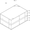
- FIG. 3 is a schematic view illustrating the electrode assembly obtained according to an embodiment of the present disclosure.
- the electrode assembly 100 is an electrode assembly 100 including a positive electrode current collector 110, a positive electrode active material layer 120, a separator 130, a negative electrode active material layer 140 and a negative electrode current collector 150 stacked successively, wherein a plurality of through-holes 160 is formed to pass through the positive electrode active material layer 120, separator 130 and the negative electrode active material layer 140, the positive electrode current collector 110 includes a first sheet-like current collector 111 and a plurality of first column-like current collectors 112 extended from the first sheet-like current collector 111 along the thickness direction of the electrode assembly 100 and passing through a part of the through-holes 160, and the negative electrode current collector 150 includes a second sheet-like current collector 151 and a plurality of second column-like current collectors 152 extended from the second sheet-like current collector 151 along the thickness direction of the electrode assembly 100 and passing through the remaining through-holes other than the part of the through-holes 160.
- an electrode assembly generally includes a positive electrode having a sheet-like positive electrode current collector and a positive electrode active material layer formed thereon, and a negative electrode including a sheet-like negative electrode current collector and a negative electrode active material layer formed thereon, stacked simply with a sheet-like separator interposed therebetween.
- the column-like current collectors 112, 152 pass through the through-holes 160 formed in the electrode active material layers 120, 140 and the separator to provide the electrode assembly. Therefore, it is possible to produce an electrode assembly in the form of a rigid block.
- the first column-like current collectors 112 may be formed in such a manner that they pass through the through-holes 160, are extended along the thickness direction of the electrode assembly 100 and reach the second sheet-like current collector 151 of the counter electrode.
- the second column-like current collectors 152 may be formed in such a manner that they pass through the through-holes 160, are extended along the thickness direction of the electrode assembly 100 and reach the first sheet-like current collector 111 of the counter electrode.
- an insulation layer may be formed at the portion where the first column-like current collectors 112 are in contact with the second sheet-like current collector 151 and at the portion where the second column-like current collectors 152 are in contact with the first sheet-like current collector 111 to interrupt electrical connection.
- first column-like current collectors 112 may pass through the through-holes 160 formed in the positive electrode active material layer 120 while being in close contact with the inner circumferential surfaces thereof.
- second column-like current collectors 152 may pass through the through-holes 160 formed in the negative electrode active material layer 140 while being in close contact with the inner circumferential surfaces thereof. Therefore, it is possible to increase the area where each electrode current collector is in contact with each electrode active material layer, and thus to reduce the internal resistance of each electrode.
- the first column-like current collectors 112 may be in close contact with the inner circumferential surfaces of the through-holes 160 formed in the positive electrode active material layer 120, but may pass through the through-holes 160 formed in the negative electrode active material layer 140 while being spaced apart from the inner circumferential surfaces thereof.
- the second column-like current collectors 152 may be in close contact with the inner circumferential surfaces of the through-holes 160 formed in the negative electrode active material layer 140, but may pass through the through-holes 160 formed in the positive electrode active material layer 120 while being spaced apart from the inner circumferential surfaces thereof.
- first column-like current collectors 112 may pass through the through-holes 160 formed in the positive electrode active material layer 120 while being in close contact with the inner circumferential surfaces thereof and may pass through the through-holes 160 formed in the negative electrode active material layer 140 while being in close contact with the inner circumferential surfaces thereof.
- second column-like current collectors 152 may pass through the through-holes 160 formed in the negative electrode active material layer 140 while being in close contact with the inner circumferential surfaces thereof and may pass through the through-holes 160 formed in the positive electrode active material layer 120 while being in close contact with the inner circumferential surfaces thereof.
- the first column-like current collectors 112 may include a first insulation layer formed on the surface of the portion where they are in contact with the negative electrode active material layer 140
- the second column-like current collectors 152 may include a second insulation layer formed on the surface of the portion where they are in contact with the positive electrode active material layer 120.
- each of the first insulation layer and the second insulation layer may independently include a varnish coating layer, insulating polymer coating layer or an insulating inorganic coating layer.
- the part of the through-holes and the remaining through-holes may be disposed with no particular limitation and may be disposed independently as a separate group at one portion.
- the part of the through-holes and the remaining through-holes may be disposed alternately with each other. In this manner, force may be applied uniformly to the first column-like current collector and to the second column-like current collectors. Thus, it is possible to assembly a more rigid electrode assembly.
- FIG. 4 is a schematic view illustrating an electrode mold configured to form an electrode active material layer according to an embodiment of the present disclosure.
- the electrode active material layer having a plurality of through-holes may be a product obtained by introducing an electrode active material slurry to an electrode mold 200 having a plurality of columns, and then heating and compressing the electrode active material slurry.
- a block-shaped electrode active material layer When a block-shaped electrode active material layer is obtained through an electrode mold, it may be stored merely by stacking without winding for storage. Thus, it is possible to fundamentally prevent separation of an electrode active material layer, which, otherwise, may occur when an electrode sheet is wound for storage according to the related art.
- the positive electrode active material slurry according to the present disclosure is prepared by mixing a positive electrode active material, a conductive material, a binder and a solvent.
- the positive electrode active material may include a lithium-containing oxide, and a lithium-containing transition metal oxide may be used preferably.
- a lithium-containing transition metal oxide may be used preferably.
- it is possible to use any one selected from the group consisting of Li x CoO 2 (0.5 ⁇ x ⁇ 1.3), Li x NiO 2 (0.5 ⁇ x ⁇ 1.3), Li x MnO 2 (0.5 ⁇ x ⁇ 1.3), Li x Mn 2 O 4 (0.5 ⁇ x ⁇ 1.3), Li x (Ni a Co b Mn c )O 2 (0.5 ⁇ x ⁇ 1.3, 0 ⁇ a ⁇ 1, 0 ⁇ b ⁇ 1, 0 ⁇ c ⁇ 1, a + b + c 1), Li x Ni 1 - y Co y O 2 (0.5 ⁇ x ⁇ 1.3, 0 ⁇ y ⁇ 1), Li x Co 1-y Mn y O 2 (0.5 ⁇ x ⁇
- the conductive material is not particularly limited, as long as it is an electroconductive material causing no chemical change in an electrochemical device.
- the conductive material that may be used includes carbon black, graphite, carbon fibers, carbon nanotubes, metal powder, conductive metal oxide, inorganic conductive material, or the like.
- Particular examples of commercially available conductive materials include acetylene black series (available from Chevron Chemical Company or Gulf Oil Company), Ketjen Black EC series (available from Armak Company), Vulcan XC-72 (available from Cabot Company) and Super P (available from MMM Company).
- acetylene black series available from Chevron Chemical Company or Gulf Oil Company
- Ketjen Black EC series available from Armak Company
- Vulcan XC-72 available from Cabot Company
- Super P available from MMM Company
- the negative electrode active material slurry according to the present disclosure is prepared by mixing a negative electrode active material, a conductive material, a binder and a solvent.
- the negative electrode active material may include lithium metal, a carbonaceous material, metal compound or a combination thereof, which is capable of lithium ion intercalation/deintercalation.
- the carbonaceous material may include low-crystalline carbon and high-crystalline carbon.
- Typical examples of low-crystalline carbon include soft carbon and hard carbon
- those of high-crystalline carbon include natural graphite, Kish graphite, pyrolytic carbon, mesophase pitch based carbon fibers, meso-carbon microbeads, mesophase pitches and high-temperature baked carbon, such as petroleum or coal tar pitch derived cokes.
- the metal compound include compounds containing at least one of metal elements, such as Si, Ge, Sn, Pb, P, Sb, Bi, Al, Ga, In, Ti, Mn, Fe, Co, Ni, Cu, Zn, Ag, Mg, Sr and Ba.
- the metal compound may be used in any form, such as simple substance, alloy, oxide (TiO 2 , SnO 2 , or the like), nitride, sulfide, boride or alloy with lithium.
- a metal compound that may contain at least one element selected from Si, Ge and Sn and includes at least one element selected from Si and Sn may provide a battery with higher capacity.
- the binder used for the positive electrode and the negative electrode functions to connect positive electrode active material particles and negative electrode active material particles among themselves. It is possible to use a conventional binder with no particular limitation.
- binders such as polyvinylidene fluoride-co-hexafluoropropylene (PVDF-co-HFP), polyvinylidene fluoride (PVDF), polyacrylonitrile, polymethyl methacrylate, styrene butadiene rubber (SBR) and carboxymethyl cellulose (CMC).
- PVDF-co-HFP polyvinylidene fluoride-co-hexafluoropropylene
- PVDF polyvinylidene fluoride
- SBR styrene butadiene rubber
- CMC carboxymethyl cellulose
- each of the positive electrode current collector and the negative electrode current collector may be any highly conductive metal that has no reactivity in the voltage range of the corresponding battery.
- the positive electrode current collector include foil made of aluminum, nickel or a combination thereof.
- the negative electrode current collector include foil made of copper, gold, nickel, copper alloy or a combination thereof.
- the current collector may include stacked substrates made of such materials.
- the separator according to the present disclosure may be any porous polymer substrate used for a conventional electrochemical device.
- the separator may include a polyolefin-based porous polymer membrane or non-woven web, but is not limited thereto.
- polystyrene-based porous polymer membrane examples include membranes formed of any one of polyolefin polymers, such as polyethylene, including high-density polyethylene, linear low-density polyethylene, low-density polyethylene and ultrahigh-molecular weight polyethylene, polypropylene, polybutylene and polypentene, or a polymer blend thereof.
- polyethylene including high-density polyethylene, linear low-density polyethylene, low-density polyethylene and ultrahigh-molecular weight polyethylene, polypropylene, polybutylene and polypentene, or a polymer blend thereof.
- the non-woven web include a non-woven web formed of any one of polyethylene terephthalate, polybutylene terephthalate, polyester, polyacetal, polyamide, polycarbonate, polyimide, polyetheretherketone, polyethersulfone, polyphenylene oxide, polyphenylene sulfide and polyethylene naphthalate, or a polymer blend thereof, in addition to a polyolefin-based non-woven web.
- the non-woven web may have a structure of a spun-bonded non-woven web including long fibers or a melt blown non-woven web.
- the porous polymer substrate may have a thickness of 5-50 ⁇ m.
- the pore size and porosity of the pores present in the porous polymer substrate are not particularly limited, the pore size and porosity may be 0.01-50 ⁇ m and 10-95%, respectively.
- the electrode assembly according to the present disclosure may be used for manufacturing an electrochemical device.
- the electrochemical device includes any device which carries out electrochemical reaction, and particular examples thereof include all types of secondary batteries, fuel cells, solar cells or capacitors such as super capacitor devices.
- the secondary batteries lithium secondary batteries, including lithium metal secondary batteries, lithium ion secondary batteries, lithium polymer secondary batteries or lithium ion polymer ion batteries, are preferred.
Landscapes
- Chemical & Material Sciences (AREA)
- Chemical Kinetics & Catalysis (AREA)
- Electrochemistry (AREA)
- General Chemical & Material Sciences (AREA)
- Engineering & Computer Science (AREA)
- Manufacturing & Machinery (AREA)
- Materials Engineering (AREA)
- Battery Electrode And Active Subsutance (AREA)
- Secondary Cells (AREA)
- Cell Electrode Carriers And Collectors (AREA)
- Electric Double-Layer Capacitors Or The Like (AREA)
- Cell Separators (AREA)
- Fuel Cell (AREA)
Abstract
Description
- The present application claims priority to Korean Patent Application No.
10-2017-0081480 filed on June 27, 2017 - The present disclosure relates to an electrode assembly and a lithium secondary battery including the same. More particularly, the present disclosure relates to an electrode assembly including a positive electrode, a separator and a negative electrode stacked in a novel shape, and a lithium secondary battery including the same.
- Recently, energy storage technology has been given increasing attentions. Efforts into research and development for electrochemical devices have been actualized more and more, as the application of energy storage technology has been extended to energy for cellular phones, camcorders and notebook PC and even to energy for electric vehicles. In this context, electrochemical devices have been most spotlighted. Particularly, electronic instruments have been downsized and lightened recently, development of secondary batteries as batteries amenable to downsizing and lightening and capable of being charged/discharged with high capacity has been focused.
- Secondary batteries having improved performance, particularly output, have been developed continuously through the use of an electrode active material. Among the commercially available secondary batteries, lithium secondary batteries developed in the early 1990's have been spotlighted, since they have a higher driving voltage and significantly higher energy density as compared to conventional batteries, such as Ni-MH batteries.
- Such a lithium secondary battery includes a positive electrode, a separator, a negative electrode and an electrolyte. Lithium ions deintercalated from a positive electrode active material upon the first charge are intercalated into a negative electrode active material, such as carbon particles, and then deintercalated again therefrom upon discharge. In this manner, lithium ions function to transfer energy, while they reciprocate between both electrodes, and thus the lithium secondary battery is rechargeable.
- As technological development and a need for mobile instruments have increased, a demand for secondary batteries as energy sources has increased rapidly. Among such secondary batteries, lithium secondary batteries having high energy density and voltage, long cycle life and a low self-discharging rate have been commercialized and used widely. In addition, as the attention to environmental problems has increased, there has been grown the market of systems using a high-capacity battery, such as electric vehicles and hybrid electric vehicles capable of substituting for vehicles using fossil fuel, including gasoline vehicles and diesel vehicles, one of the main causes of air pollution. In addition, as a power source for such systems, there is a need for designing a high-capacity electrode for manufacturing a lithium secondary battery having high energy density, high output and high discharge voltage.
- Meanwhile, there has been an attempt to provide a high-loading electrode (loading amount: about 6 mAh/cm2 or more) having a large electrode thickness by increasing the amount of an electrode active material for the purpose of designing an electrode with high capacity. However, when such a high-loading electrode is to be realized, there are problems in that cracking occurs at a coating portion due to high loading, non-uniform loading occurs due to the viscosity of an electrode active material slurry and separation of an electrode active material occurs during the winding of the electrode.
- The present disclosure is designed to solve the problems of the related art, and therefore the present disclosure is directed to providing an electrode assembly having a novel shape capable of preventing cracking and separation of an electrode active material layer and a lithium secondary battery including the same.
- In one aspect of the present disclosure, there is provided an electrode assembly including a positive electrode current collector, a positive electrode active material layer, a separator, a negative electrode active material layer and a negative electrode current collector stacked successively, wherein a plurality of through-holes is formed to pass through the positive electrode active material layer, separator and the negative electrode active material layer, the positive electrode current collector includes a first sheet-like current collector and a plurality of first column-like current collectors extended from the first sheet-like current collector along the thickness direction of the electrode assembly and passing through a part of the through-holes, and the negative electrode current collector includes a second sheet-like current collector and a plurality of second column-like current collectors extended from the second sheet-like current collector along the thickness direction of the electrode assembly and passing through the remaining through-holes other than the part of the through-holes.
- Herein, the first column-like current collectors may be formed in such a manner that they are extended along the thickness direction of the electrode assembly to reach the second sheet-like current collector.
- In addition, the second column-like current collectors may be formed in such a manner that they are extended along the thickness direction of the electrode assembly to reach the first sheet-like current collector.
- Meanwhile, the first column-like current collectors may pass through the through-holes formed in the positive electrode active material layer while being in close contact with the inner circumferential surfaces thereof, and the second column-like current collectors may pass through the through-holes formed in the negative electrode active material layer while being in close contact with the inner circumferential surfaces thereof.
- Herein, the first column-like current collectors may pass through the through-holes formed in the negative electrode active material layer while being spaced apart from the inner circumferential surfaces thereof, and the second column-like current collectors may pass through the through-holes formed in the positive electrode active material layer while being spaced apart from the inner circumferential surfaces thereof.
- In addition, the first column-like current collectors may pass through the through-holes formed in the negative electrode active material layer while being in close contact with the inner circumferential surfaces thereof, the second column-like current collectors may pass through the through-holes formed in the positive electrode active material layer while being in close contact with the inner circumferential surfaces thereof, the first column-like current collectors includes a first insulation layer formed on the surface of the portion where they are in contact with the negative electrode active material layer, and the second column-like current collectors includes a second insulation layer formed on the surface of the portion where they are in contact with the positive electrode active material layer.
- Herein, each of the first insulation layer and the second insulation layer may be independently a varnish coating layer, insulating polymer coating layer or an insulating inorganic coating layer.
- Meanwhile, the part of the through-holes through which the first column-like current collectors pass and the remaining through-holes through which the second column-like current collectors pass may be disposed alternately with each other.
- In addition, the positive electrode active material layer in which the through-holes are formed may be a product obtained by introducing a positive electrode active material slurry to an electrode mold having a plurality of columns, and then heating and compressing the positive electrode active material slurry.
- In addition, the negative electrode active material layer in which the through-holes are formed may be a product obtained by introducing a negative electrode active material slurry to an electrode mold having a plurality of columns, and then heating and compressing the negative electrode active material slurry.
- In another aspect of the present disclosure, there is also provided a lithium secondary battery including the electrode assembly according to the present disclosure.
- According to the present disclosure, column-like current collectors pass through a plurality of through-holes formed in electrode active material layers to provide an electrode assembly. Thus, it is possible to produce an electrode assembly having a rigid block shape.
- In addition, a positive electrode current collector, a positive electrode active material layer, a negative electrode active material layer and a negative electrode current collector are stacked in a block shape to produce an electrode assembly. Thus, it is possible to reduce the processing cost.
- Further, the column-like current collectors passing through the electrode active material layers are in close contact with the inner circumferential surfaces of the through-holes formed in the electrode active material layers. Thus, it is possible to reduce the internal resistance of the electrode.
- The accompanying drawings illustrate a preferred embodiment of the present disclosure and together with the foregoing disclosure, serve to provide further understanding of the technical features of the present disclosure, and thus, the present disclosure is not construed as being limited to the drawing.
-
FIG. 1 is a schematic view illustrating a positive electrode current collector and a negative electrode current collector according to an embodiment of the present disclosure. -
FIG. 2 is a schematic view illustrating a positive electrode active material layer, separator and a negative electrode active material layer having a plurality of through-holes according to an embodiment of the present disclosure. -
FIG. 3 is a schematic view illustrating the electrode assembly obtained according to an embodiment of the present disclosure. -
FIG. 4 is a schematic view illustrating an electrode mold configured to form an electrode active material layer according to an embodiment of the present disclosure. - Hereinafter, preferred embodiments of the present disclosure will be described in detail with reference to the accompanying drawings. Prior to the description, it should be understood that the terms used in the specification and the appended claims should not be construed as limited to general and dictionary meanings, but interpreted based on the meanings and concepts corresponding to technical aspects of the present disclosure on the basis of the principle that the inventor is allowed to define terms appropriately for the best explanation.
- Therefore, the description proposed herein is just a preferable example for the purpose of illustrations only, not intended to limit the scope of the disclosure, so it should be understood that other equivalents and modifications could be made thereto without departing from the scope of the disclosure.
-
FIG. 1 is a schematic view illustrating a positive electrode current collector and a negative electrode current collector according to an embodiment of the present disclosure,FIG. 2 is a schematic view illustrating a positive electrode active material layer, separator and a negative electrode active material layer having a plurality of through-holes according to an embodiment of the present disclosure, andFIG. 3 is a schematic view illustrating the electrode assembly obtained according to an embodiment of the present disclosure. - Referring to
FIG. 1 to FIG. 3 , theelectrode assembly 100 according to an embodiment of the present disclosure is anelectrode assembly 100 including a positiveelectrode current collector 110, a positive electrodeactive material layer 120, aseparator 130, a negative electrodeactive material layer 140 and a negativeelectrode current collector 150 stacked successively, wherein a plurality of through-holes 160 is formed to pass through the positive electrodeactive material layer 120,separator 130 and the negative electrodeactive material layer 140, the positive electrodecurrent collector 110 includes a first sheet-likecurrent collector 111 and a plurality of first column-likecurrent collectors 112 extended from the first sheet-likecurrent collector 111 along the thickness direction of theelectrode assembly 100 and passing through a part of the through-holes 160, and the negativeelectrode current collector 150 includes a second sheet-likecurrent collector 151 and a plurality of second column-likecurrent collectors 152 extended from the second sheet-likecurrent collector 151 along the thickness direction of theelectrode assembly 100 and passing through the remaining through-holes other than the part of the through-holes 160. - According to the related art, an electrode assembly generally includes a positive electrode having a sheet-like positive electrode current collector and a positive electrode active material layer formed thereon, and a negative electrode including a sheet-like negative electrode current collector and a negative electrode active material layer formed thereon, stacked simply with a sheet-like separator interposed therebetween.
- When a high-loading electrode having a large electrode thickness is provided from the conventional electrode assembly by increasing the amount of electrode active materials in order to design a high-capacity electrode, some problems, such as cracking at a coating portion caused by high loading, non-uniform loading caused by the viscosity of an electrode active material slurry and separation of an electrode active material layer during the winding of an electrode, occur undesirably.
- However, according to the present disclosure, the column-like
current collectors holes 160 formed in the electrodeactive material layers - In addition, it is possible to reduce the processing cost, since each of the preliminarily formed block-shaped positive electrode
current collector 110, positive electrodeactive material layer 120,separator 130, negative electrodeactive material layer 140 and negative electrodecurrent collector 150 are stacked successively to produce theelectrode assembly 100. - Herein, the first column-like
current collectors 112 may be formed in such a manner that they pass through the through-holes 160, are extended along the thickness direction of theelectrode assembly 100 and reach the second sheet-likecurrent collector 151 of the counter electrode. The second column-likecurrent collectors 152 may be formed in such a manner that they pass through the through-holes 160, are extended along the thickness direction of theelectrode assembly 100 and reach the first sheet-likecurrent collector 111 of the counter electrode. - In this case, in order to prevent a short-circuit between both electrodes, an insulation layer may be formed at the portion where the first column-like
current collectors 112 are in contact with the second sheet-likecurrent collector 151 and at the portion where the second column-likecurrent collectors 152 are in contact with the first sheet-likecurrent collector 111 to interrupt electrical connection. - Meanwhile, the first column-like
current collectors 112 may pass through the through-holes 160 formed in the positive electrodeactive material layer 120 while being in close contact with the inner circumferential surfaces thereof. In addition, the second column-likecurrent collectors 152 may pass through the through-holes 160 formed in the negative electrodeactive material layer 140 while being in close contact with the inner circumferential surfaces thereof. Therefore, it is possible to increase the area where each electrode current collector is in contact with each electrode active material layer, and thus to reduce the internal resistance of each electrode. - Herein, in order to prevent a short-circuit between both electrodes, the first column-like
current collectors 112 may be in close contact with the inner circumferential surfaces of the through-holes 160 formed in the positive electrodeactive material layer 120, but may pass through the through-holes 160 formed in the negative electrodeactive material layer 140 while being spaced apart from the inner circumferential surfaces thereof. The second column-likecurrent collectors 152 may be in close contact with the inner circumferential surfaces of the through-holes 160 formed in the negative electrodeactive material layer 140, but may pass through the through-holes 160 formed in the positive electrodeactive material layer 120 while being spaced apart from the inner circumferential surfaces thereof. - In addition, the first column-like
current collectors 112 may pass through the through-holes 160 formed in the positive electrodeactive material layer 120 while being in close contact with the inner circumferential surfaces thereof and may pass through the through-holes 160 formed in the negative electrodeactive material layer 140 while being in close contact with the inner circumferential surfaces thereof. In addition, the second column-likecurrent collectors 152 may pass through the through-holes 160 formed in the negative electrodeactive material layer 140 while being in close contact with the inner circumferential surfaces thereof and may pass through the through-holes 160 formed in the positive electrodeactive material layer 120 while being in close contact with the inner circumferential surfaces thereof. Herein, in order to prevent a short-circuit between both electrodes, the first column-likecurrent collectors 112 may include a first insulation layer formed on the surface of the portion where they are in contact with the negative electrodeactive material layer 140, and the second column-likecurrent collectors 152 may include a second insulation layer formed on the surface of the portion where they are in contact with the positive electrodeactive material layer 120. - Herein, each of the first insulation layer and the second insulation layer may independently include a varnish coating layer, insulating polymer coating layer or an insulating inorganic coating layer.
- Meanwhile, referring to the arrangement of a part of the through-holes through which the first column-like current collectors pass and the remaining through-holes through which the second column-like current collectors pass, the part of the through-holes and the remaining through-holes may be disposed with no particular limitation and may be disposed independently as a separate group at one portion. In a variant, the part of the through-holes and the remaining through-holes may be disposed alternately with each other. In this manner, force may be applied uniformly to the first column-like current collector and to the second column-like current collectors. Thus, it is possible to assembly a more rigid electrode assembly.
-
FIG. 4 is a schematic view illustrating an electrode mold configured to form an electrode active material layer according to an embodiment of the present disclosure. - Referring to
FIG. 4 , the electrode active material layer having a plurality of through-holes according to the present disclosure may be a product obtained by introducing an electrode active material slurry to anelectrode mold 200 having a plurality of columns, and then heating and compressing the electrode active material slurry. - When a block-shaped electrode active material layer is obtained through an electrode mold, it may be stored merely by stacking without winding for storage. Thus, it is possible to fundamentally prevent separation of an electrode active material layer, which, otherwise, may occur when an electrode sheet is wound for storage according to the related art.
- Herein, the positive electrode active material slurry according to the present disclosure is prepared by mixing a positive electrode active material, a conductive material, a binder and a solvent.
- The positive electrode active material may include a lithium-containing oxide, and a lithium-containing transition metal oxide may be used preferably. For examples, it is possible to use any one selected from the group consisting of LixCoO2 (0.5 < x < 1.3), LixNiO2 (0.5 < x < 1.3), LixMnO2 (0.5 < x < 1.3), LixMn2O4 (0.5 < x < 1.3), Lix(NiaCobMnc)O2 (0.5 < x < 1.3, 0 < a < 1, 0 < b < 1, 0 < c < 1, a + b + c = 1), LixNi1-yCoyO2 (0.5 < x < 1.3, 0 < y < 1), LixCo1-yMnyO2 (0.5 < x < 1.3, 0 ≤ y < 1), LixNi1-yMnyO2 (0.5 < x < 1.3, O ≤ y < 1), Lix(NiaCobMnc)O4 (0.5 < x < 1.3, 0 < a < 2, 0 < b < 2, 0 < c < 2, a + b + c = 2), LixMn2-zNizO4 (0.5 < x < 1.3, 0 < z < 2), LixMn2-zCozO4 (0.5 < x < 1.3, 0 < z < 2), LixCoPO4 (0.5 < x < 1.3) and LixFePO4 (0.5 < x < 1.3), or a combination of two or more of them. The lithium-containing transition metal oxide may be coated with a metal, such as aluminum (Al), or metal oxide. It is also possible to use a sulfide, selenide and halide, besides the lithium-containing transition metal oxide.
- The conductive material is not particularly limited, as long as it is an electroconductive material causing no chemical change in an electrochemical device. In general, the conductive material that may be used includes carbon black, graphite, carbon fibers, carbon nanotubes, metal powder, conductive metal oxide, inorganic conductive material, or the like. Particular examples of commercially available conductive materials include acetylene black series (available from Chevron Chemical Company or Gulf Oil Company), Ketjen Black EC series (available from Armak Company), Vulcan XC-72 (available from Cabot Company) and Super P (available from MMM Company). For example, it is possible to use acetylene black, carbon black, graphite, or the like.
- In addition, the negative electrode active material slurry according to the present disclosure is prepared by mixing a negative electrode active material, a conductive material, a binder and a solvent.
- In general, the negative electrode active material may include lithium metal, a carbonaceous material, metal compound or a combination thereof, which is capable of lithium ion intercalation/deintercalation.
- Particular examples of the carbonaceous material may include low-crystalline carbon and high-crystalline carbon. Typical examples of low-crystalline carbon include soft carbon and hard carbon, and those of high-crystalline carbon include natural graphite, Kish graphite, pyrolytic carbon, mesophase pitch based carbon fibers, meso-carbon microbeads, mesophase pitches and high-temperature baked carbon, such as petroleum or coal tar pitch derived cokes.
- Particular examples of the metal compound include compounds containing at least one of metal elements, such as Si, Ge, Sn, Pb, P, Sb, Bi, Al, Ga, In, Ti, Mn, Fe, Co, Ni, Cu, Zn, Ag, Mg, Sr and Ba. The metal compound may be used in any form, such as simple substance, alloy, oxide (TiO2, SnO2, or the like), nitride, sulfide, boride or alloy with lithium. However, it is possible to impart high capacity to simple substance, alloy, oxide and alloy with lithium. Among them, a metal compound that may contain at least one element selected from Si, Ge and Sn and includes at least one element selected from Si and Sn may provide a battery with higher capacity.
- The binder used for the positive electrode and the negative electrode functions to connect positive electrode active material particles and negative electrode active material particles among themselves. It is possible to use a conventional binder with no particular limitation.
- For example, it is possible to use various types of binders, such as polyvinylidene fluoride-co-hexafluoropropylene (PVDF-co-HFP), polyvinylidene fluoride (PVDF), polyacrylonitrile, polymethyl methacrylate, styrene butadiene rubber (SBR) and carboxymethyl cellulose (CMC).
- Meanwhile, each of the positive electrode current collector and the negative electrode current collector may be any highly conductive metal that has no reactivity in the voltage range of the corresponding battery. Particularly, non-limiting examples of the positive electrode current collector include foil made of aluminum, nickel or a combination thereof. Non-limiting examples of the negative electrode current collector include foil made of copper, gold, nickel, copper alloy or a combination thereof. In addition, the current collector may include stacked substrates made of such materials.
- In addition, the separator according to the present disclosure may be any porous polymer substrate used for a conventional electrochemical device. For example, the separator may include a polyolefin-based porous polymer membrane or non-woven web, but is not limited thereto.
- Particular examples of the polyolefin-based porous polymer membrane include membranes formed of any one of polyolefin polymers, such as polyethylene, including high-density polyethylene, linear low-density polyethylene, low-density polyethylene and ultrahigh-molecular weight polyethylene, polypropylene, polybutylene and polypentene, or a polymer blend thereof.
- Particular examples of the non-woven web include a non-woven web formed of any one of polyethylene terephthalate, polybutylene terephthalate, polyester, polyacetal, polyamide, polycarbonate, polyimide, polyetheretherketone, polyethersulfone, polyphenylene oxide, polyphenylene sulfide and polyethylene naphthalate, or a polymer blend thereof, in addition to a polyolefin-based non-woven web. The non-woven web may have a structure of a spun-bonded non-woven web including long fibers or a melt blown non-woven web.
- There is no particular limitation in the thickness of the porous polymer substrate, but the porous polymer substrate may have a thickness of 5-50 µm. Although the pore size and porosity of the pores present in the porous polymer substrate are not particularly limited, the pore size and porosity may be 0.01-50 µm and 10-95%, respectively.
- Meanwhile, the electrode assembly according to the present disclosure may be used for manufacturing an electrochemical device. Herein, the electrochemical device includes any device which carries out electrochemical reaction, and particular examples thereof include all types of secondary batteries, fuel cells, solar cells or capacitors such as super capacitor devices. Particularly, among the secondary batteries, lithium secondary batteries, including lithium metal secondary batteries, lithium ion secondary batteries, lithium polymer secondary batteries or lithium ion polymer ion batteries, are preferred.
- The present disclosure has been described in detail. However, it should be understood that the detailed description and specific examples, while indicating preferred embodiments of the disclosure, are given by way of illustration only, since various changes and modifications within the scope of the disclosure will become apparent to those skilled in the art from this detailed description.
-
- 100:
- Electrode assembly
- 110:
- Positive electrode current collector
- 111:
- First sheet-like current collector
- 112:
- First column-like current collector
- 120:
- Positive electrode active material layer
- 130:
- Separator
- 140:
- Negative electrode active material layer
- 150:
- Negative electrode current collector
- 151:
- Second sheet-like current collector
- 152:
- Second column-like current collector
- 160:
- Through-holes
- 200:
- Electrode mold
Claims (11)
- An electrode assembly comprising a positive electrode current collector, a positive electrode active material layer, a separator, a negative electrode active material layer and a negative electrode current collector stacked successively,
wherein a plurality of through-holes is formed to pass through the positive electrode active material layer, separator and the negative electrode active material layer,
the positive electrode current collector comprises a first sheet-like current collector and a plurality of first column-like current collectors extended from the first sheet-like current collector along the thickness direction of the electrode assembly and passing through a part of the through-holes, and
the negative electrode current collector comprises a second sheet-like current collector and a plurality of second column-like current collectors extended from the second sheet-like current collector along the thickness direction of the electrode assembly and passing through the remaining through-holes other than the part of through-holes. - The electrode assembly according to claim 1, wherein the first column-like current collectors are formed in such a manner that they are extended along the thickness direction of the electrode assembly to reach the second sheet-like current collector.
- The electrode assembly according to claim 1, wherein the second column-like current collectors are formed in such a manner that they are extended along the thickness direction of the electrode assembly to reach the first sheet-like current collector.
- The electrode assembly according to claim 1, wherein the first column-like current collectors pass through the through-holes formed in the positive electrode active material layer while being in close contact with the inner circumferential surfaces thereof, and
the second column-like current collectors pass through the through-holes formed in the negative electrode active material layer while being in close contact with the inner circumferential surfaces thereof. - The electrode assembly according to claim 4, wherein the first column-like current collectors pass through the through-holes formed in the negative electrode active material layer while being spaced apart from the inner circumferential surfaces thereof, and
the second column-like current collectors pass through the through-holes formed in the positive electrode active material layer while being spaced apart from the inner circumferential surfaces thereof. - The electrode assembly according to claim 4, wherein the first column-like current collectors pass through the through-holes formed in the negative electrode active material layer while being in close contact with the inner circumferential surfaces thereof,
the second column-like current collectors pass through the through-holes formed in the positive electrode active material layer while being in close contact with the inner circumferential surfaces thereof,
the first column-like current collectors comprises a first insulation layer formed on the surface of the portion where they are in contact with the negative electrode active material layer, and
the second column-like current collectors comprises a second insulation layer formed on the surface of the portion where they are in contact with the positive electrode active material layer. - The electrode assembly according to claim 6, wherein each of the first insulation layer and the second insulation layer is independently a varnish coating layer, insulating polymer coating layer or an insulating inorganic coating layer.
- The electrode assembly according to claim 1, wherein the part of the through-holes through which the first column-like current collectors pass and the remaining through-holes through which the second column-like current collectors pass are disposed alternately with each other.
- The electrode assembly according to claim 1, wherein the positive electrode active material layer in which the through-holes are formed is a product obtained by introducing a positive electrode active material slurry to an electrode mold having a plurality of columns, and then heating and compressing the positive electrode active material slurry.
- The electrode assembly according to claim 1, wherein the negative electrode active material layer in which the through-holes are formed is a product obtained by introducing a negative electrode active material slurry to an electrode mold having a plurality of columns, and then heating and compressing the negative electrode active material slurry.
- A lithium secondary battery comprising the electrode assembly as defined in any one of claims 1 to 10.
Priority Applications (1)
| Application Number | Priority Date | Filing Date | Title |
|---|---|---|---|
| PL18823670T PL3534450T3 (en) | 2017-06-27 | 2018-06-21 | Electrode assembly and lithium secondary battery including the same |
Applications Claiming Priority (2)
| Application Number | Priority Date | Filing Date | Title |
|---|---|---|---|
| KR1020170081480A KR102208515B1 (en) | 2017-06-27 | 2017-06-27 | Electrode assembly and lithium secondary battery including the same |
| PCT/KR2018/007033 WO2019004655A1 (en) | 2017-06-27 | 2018-06-21 | Electrode assembly and lithium secondary battery comprising same |
Publications (3)
| Publication Number | Publication Date |
|---|---|
| EP3534450A1 true EP3534450A1 (en) | 2019-09-04 |
| EP3534450A4 EP3534450A4 (en) | 2019-11-13 |
| EP3534450B1 EP3534450B1 (en) | 2020-11-25 |
Family
ID=64742386
Family Applications (1)
| Application Number | Title | Priority Date | Filing Date |
|---|---|---|---|
| EP18823670.7A Active EP3534450B1 (en) | 2017-06-27 | 2018-06-21 | Electrode assembly and lithium secondary battery including the same |
Country Status (7)
| Country | Link |
|---|---|
| US (1) | US11081762B2 (en) |
| EP (1) | EP3534450B1 (en) |
| JP (1) | JP7037015B2 (en) |
| KR (1) | KR102208515B1 (en) |
| CN (2) | CN109148797B (en) |
| PL (1) | PL3534450T3 (en) |
| WO (1) | WO2019004655A1 (en) |
Families Citing this family (8)
| Publication number | Priority date | Publication date | Assignee | Title |
|---|---|---|---|---|
| US20220320539A1 (en) * | 2014-12-03 | 2022-10-06 | Global Energy Science, Llc | Unique electrodes for electrochemical cells |
| KR102208515B1 (en) * | 2017-06-27 | 2021-01-26 | 주식회사 엘지화학 | Electrode assembly and lithium secondary battery including the same |
| JP7067019B2 (en) * | 2017-10-30 | 2022-05-16 | セイコーエプソン株式会社 | Secondary battery electrode, secondary battery, electronic device, secondary battery electrode manufacturing method, secondary battery manufacturing method |
| WO2020237015A1 (en) * | 2019-05-22 | 2020-11-26 | Sion Power Corporation | Electrically coupled electrodes, and associated articles and methods |
| FR3110774B1 (en) * | 2020-05-20 | 2022-04-15 | I Ten | Method of manufacturing a lithium ion battery |
| KR102699227B1 (en) | 2020-05-14 | 2024-08-26 | 서강대학교산학협력단 | Apparatus for counting bullet casing |
| PL3989326T3 (en) | 2020-05-14 | 2024-07-01 | Lg Energy Solution, Ltd. | Electrode assembly having enhanced safety and lithium secondary battery comprising same |
| WO2025024963A1 (en) * | 2023-07-28 | 2025-02-06 | 江苏新宜中澳环境技术有限公司 | Electrode device for a plurality of membrane capacitive deionization electrode assemblies |
Family Cites Families (19)
| Publication number | Priority date | Publication date | Assignee | Title |
|---|---|---|---|---|
| KR20070037209A (en) | 2005-09-30 | 2007-04-04 | 삼성에스디아이 주식회사 | Fuel cell using liquid fuel |
| JP5135746B2 (en) | 2006-09-21 | 2013-02-06 | トヨタ自動車株式会社 | Lithium ion secondary battery and manufacturing method thereof |
| JP2008270153A (en) * | 2006-11-15 | 2008-11-06 | Matsushita Electric Ind Co Ltd | Non-aqueous electrolyte secondary battery current collector manufacturing method, non-aqueous electrolyte secondary battery electrode manufacturing method, and non-aqueous electrolyte secondary battery |
| JP5224020B2 (en) * | 2007-06-18 | 2013-07-03 | エス・イー・アイ株式会社 | Lithium secondary battery |
| JP2009076289A (en) | 2007-09-20 | 2009-04-09 | Seiko Epson Corp | Arc tube manufacturing method, light source device and projector |
| US8927156B2 (en) | 2009-02-19 | 2015-01-06 | Semiconductor Energy Laboratory Co., Ltd. | Power storage device |
| JP2011151279A (en) | 2010-01-25 | 2011-08-04 | Sony Corp | Composite electrode, and electronic device using the same |
| JP2012059396A (en) * | 2010-09-06 | 2012-03-22 | Mitsubishi Electric Corp | Negative electrode for power storage device and power storage device, and method of manufacturing them |
| US8962190B1 (en) * | 2010-12-17 | 2015-02-24 | Hrl Laboratories, Llc | Three-dimensional electrodes with conductive foam for electron and lithium-ion transport |
| JP6050073B2 (en) | 2011-09-30 | 2016-12-21 | 株式会社半導体エネルギー研究所 | Power storage device |
| JP6050106B2 (en) | 2011-12-21 | 2016-12-21 | 株式会社半導体エネルギー研究所 | Method for producing silicon negative electrode for non-aqueous secondary battery |
| JP2013182810A (en) * | 2012-03-02 | 2013-09-12 | Tdk Corp | Collector, and lithium ion secondary battery using the same |
| US20130236781A1 (en) | 2012-03-06 | 2013-09-12 | Semiconductor Energy Laboratory Co., Ltd. | Negative electrode for secondary battery and secondary battery |
| JP2013206705A (en) * | 2012-03-28 | 2013-10-07 | Toyota Industries Corp | Power storage device, secondary battery and manufacturing method of power storage device |
| KR101562435B1 (en) | 2013-10-23 | 2015-10-22 | 전남대학교산학협력단 | Method for manufacturing solar cell with 3-dimensional absorber layer using aao template |
| JP6316066B2 (en) | 2014-03-31 | 2018-04-25 | 積水化学工業株式会社 | Method for producing lithium ion secondary battery |
| KR101686600B1 (en) | 2014-07-04 | 2016-12-14 | 주식회사 엘지화학 | Battery Cell Having Hole for Electrolyte Wetting |
| KR101741412B1 (en) * | 2014-10-29 | 2017-05-30 | 에스케이이노베이션 주식회사 | Current collector for secondary battery, electrode for secondary battery and secondary battery using the same |
| KR102208515B1 (en) * | 2017-06-27 | 2021-01-26 | 주식회사 엘지화학 | Electrode assembly and lithium secondary battery including the same |
-
2017
- 2017-06-27 KR KR1020170081480A patent/KR102208515B1/en active Active
-
2018
- 2018-06-13 CN CN201810606642.4A patent/CN109148797B/en active Active
- 2018-06-13 CN CN201820914035.XU patent/CN208400926U/en active Active
- 2018-06-21 US US16/478,764 patent/US11081762B2/en active Active
- 2018-06-21 WO PCT/KR2018/007033 patent/WO2019004655A1/en not_active Ceased
- 2018-06-21 PL PL18823670T patent/PL3534450T3/en unknown
- 2018-06-21 EP EP18823670.7A patent/EP3534450B1/en active Active
- 2018-06-21 JP JP2019526327A patent/JP7037015B2/en active Active
Also Published As
| Publication number | Publication date |
|---|---|
| CN208400926U (en) | 2019-01-18 |
| JP2019536230A (en) | 2019-12-12 |
| WO2019004655A1 (en) | 2019-01-03 |
| KR20190001461A (en) | 2019-01-04 |
| CN109148797B (en) | 2021-10-01 |
| EP3534450A4 (en) | 2019-11-13 |
| PL3534450T3 (en) | 2021-04-19 |
| CN109148797A (en) | 2019-01-04 |
| EP3534450B1 (en) | 2020-11-25 |
| US20200052276A1 (en) | 2020-02-13 |
| US11081762B2 (en) | 2021-08-03 |
| JP7037015B2 (en) | 2022-03-16 |
| KR102208515B1 (en) | 2021-01-26 |
Similar Documents
| Publication | Publication Date | Title |
|---|---|---|
| EP3534450B1 (en) | Electrode assembly and lithium secondary battery including the same | |
| US10454096B2 (en) | Negative electrode for lithium secondary battery and lithium secondary battery comprising the same | |
| KR101512251B1 (en) | Secondary battery | |
| EP3273515A2 (en) | Electrode with perforated current collector and lithium secondary battery including the same | |
| KR101647910B1 (en) | Bipolar electrode and bipolar lithium-ion secondary battery using same | |
| US11075397B2 (en) | Bipolar secondary battery | |
| EP3399582B1 (en) | Lithium secondary battery | |
| US10056604B2 (en) | Cathode material composite having improved conductivity, cathode and electrochemical device having the same | |
| EP2905837B1 (en) | Electrochemical device and battery module having improved anti-vibration- resistance | |
| JP7358632B2 (en) | Battery cell for internal short circuit evaluation and method for evaluating battery cell internal short circuit using the same | |
| EP3993091A1 (en) | Electrode with binder layer formed therein and method for manufacturing same | |
| KR101613285B1 (en) | Composite electrode comprising different electrode active material and electrode assembly | |
| KR101704759B1 (en) | Stack/folding-typed electrode assembly and electrochemical device including the same | |
| EP3993089B1 (en) | Method for manufacturing electrode on which resistance layer is formed | |
| KR101602908B1 (en) | Electrode assembly and electrochemical device including the same | |
| US11735776B2 (en) | Electrolytes for electrochemical cells | |
| KR20170111517A (en) | Positive electrode and lithium secondary battery comprising the same | |
| KR20170022465A (en) | Electrode assembly of combination structure and electrochemical device including the same | |
| KR20170061461A (en) | Lithium secondary battery | |
| JP7217358B2 (en) | Negative electrode including a plurality of current collectors arranged in parallel and secondary battery including the same | |
| EP4428991A1 (en) | Battery module comprising cooling fin | |
| KR20250126219A (en) | Negative electrode, rechargeable battery and manufacturing method of negative electrode | |
| KR20260040953A (en) | Current collector and battery | |
| KR20260033940A (en) | Polymer-metal composite foil, negative electrode currentor and lithium secondary battery comprising the same, and preparing method for polymer-metal composite foil | |
| CN121464503A (en) | Method for producing an electrode and electrode produced thereby |
Legal Events
| Date | Code | Title | Description |
|---|---|---|---|
| STAA | Information on the status of an ep patent application or granted ep patent |
Free format text: STATUS: THE INTERNATIONAL PUBLICATION HAS BEEN MADE |
|
| PUAI | Public reference made under article 153(3) epc to a published international application that has entered the european phase |
Free format text: ORIGINAL CODE: 0009012 |
|
| STAA | Information on the status of an ep patent application or granted ep patent |
Free format text: STATUS: REQUEST FOR EXAMINATION WAS MADE |
|
| 17P | Request for examination filed |
Effective date: 20190529 |
|
| AK | Designated contracting states |
Kind code of ref document: A1 Designated state(s): AL AT BE BG CH CY CZ DE DK EE ES FI FR GB GR HR HU IE IS IT LI LT LU LV MC MK MT NL NO PL PT RO RS SE SI SK SM TR |
|
| AX | Request for extension of the european patent |
Extension state: BA ME |
|
| A4 | Supplementary search report drawn up and despatched |
Effective date: 20191015 |
|
| RIC1 | Information provided on ipc code assigned before grant |
Ipc: H01M 4/139 20100101ALI20191009BHEP Ipc: H01M 4/75 20060101ALI20191009BHEP Ipc: H01M 2/18 20060101ALI20191009BHEP Ipc: H01M 10/0585 20100101AFI20191009BHEP Ipc: H01M 10/052 20100101ALI20191009BHEP Ipc: H01M 4/04 20060101ALI20191009BHEP Ipc: H01M 4/13 20100101ALI20191009BHEP |
|
| GRAP | Despatch of communication of intention to grant a patent |
Free format text: ORIGINAL CODE: EPIDOSNIGR1 |
|
| STAA | Information on the status of an ep patent application or granted ep patent |
Free format text: STATUS: GRANT OF PATENT IS INTENDED |
|
| DAV | Request for validation of the european patent (deleted) | ||
| DAX | Request for extension of the european patent (deleted) | ||
| INTG | Intention to grant announced |
Effective date: 20200903 |
|
| GRAS | Grant fee paid |
Free format text: ORIGINAL CODE: EPIDOSNIGR3 |
|
| GRAA | (expected) grant |
Free format text: ORIGINAL CODE: 0009210 |
|
| STAA | Information on the status of an ep patent application or granted ep patent |
Free format text: STATUS: THE PATENT HAS BEEN GRANTED |
|
| AK | Designated contracting states |
Kind code of ref document: B1 Designated state(s): AL AT BE BG CH CY CZ DE DK EE ES FI FR GB GR HR HU IE IS IT LI LT LU LV MC MK MT NL NO PL PT RO RS SE SI SK SM TR |
|
| REG | Reference to a national code |
Ref country code: GB Ref legal event code: FG4D |
|
| REG | Reference to a national code |
Ref country code: CH Ref legal event code: EP |
|
| REG | Reference to a national code |
Ref country code: DE Ref legal event code: R096 Ref document number: 602018010195 Country of ref document: DE |
|
| REG | Reference to a national code |
Ref country code: AT Ref legal event code: REF Ref document number: 1339331 Country of ref document: AT Kind code of ref document: T Effective date: 20201215 |
|
| REG | Reference to a national code |
Ref country code: IE Ref legal event code: FG4D |
|
| REG | Reference to a national code |
Ref country code: AT Ref legal event code: MK05 Ref document number: 1339331 Country of ref document: AT Kind code of ref document: T Effective date: 20201125 |
|
| REG | Reference to a national code |
Ref country code: NL Ref legal event code: MP Effective date: 20201125 |
|
| PG25 | Lapsed in a contracting state [announced via postgrant information from national office to epo] |
Ref country code: GR Free format text: LAPSE BECAUSE OF FAILURE TO SUBMIT A TRANSLATION OF THE DESCRIPTION OR TO PAY THE FEE WITHIN THE PRESCRIBED TIME-LIMIT Effective date: 20210226 Ref country code: NO Free format text: LAPSE BECAUSE OF FAILURE TO SUBMIT A TRANSLATION OF THE DESCRIPTION OR TO PAY THE FEE WITHIN THE PRESCRIBED TIME-LIMIT Effective date: 20210225 Ref country code: FI Free format text: LAPSE BECAUSE OF FAILURE TO SUBMIT A TRANSLATION OF THE DESCRIPTION OR TO PAY THE FEE WITHIN THE PRESCRIBED TIME-LIMIT Effective date: 20201125 Ref country code: PT Free format text: LAPSE BECAUSE OF FAILURE TO SUBMIT A TRANSLATION OF THE DESCRIPTION OR TO PAY THE FEE WITHIN THE PRESCRIBED TIME-LIMIT Effective date: 20210325 Ref country code: RS Free format text: LAPSE BECAUSE OF FAILURE TO SUBMIT A TRANSLATION OF THE DESCRIPTION OR TO PAY THE FEE WITHIN THE PRESCRIBED TIME-LIMIT Effective date: 20201125 |
|
| PG25 | Lapsed in a contracting state [announced via postgrant information from national office to epo] |
Ref country code: AT Free format text: LAPSE BECAUSE OF FAILURE TO SUBMIT A TRANSLATION OF THE DESCRIPTION OR TO PAY THE FEE WITHIN THE PRESCRIBED TIME-LIMIT Effective date: 20201125 Ref country code: SE Free format text: LAPSE BECAUSE OF FAILURE TO SUBMIT A TRANSLATION OF THE DESCRIPTION OR TO PAY THE FEE WITHIN THE PRESCRIBED TIME-LIMIT Effective date: 20201125 Ref country code: LV Free format text: LAPSE BECAUSE OF FAILURE TO SUBMIT A TRANSLATION OF THE DESCRIPTION OR TO PAY THE FEE WITHIN THE PRESCRIBED TIME-LIMIT Effective date: 20201125 Ref country code: IS Free format text: LAPSE BECAUSE OF FAILURE TO SUBMIT A TRANSLATION OF THE DESCRIPTION OR TO PAY THE FEE WITHIN THE PRESCRIBED TIME-LIMIT Effective date: 20210325 Ref country code: BG Free format text: LAPSE BECAUSE OF FAILURE TO SUBMIT A TRANSLATION OF THE DESCRIPTION OR TO PAY THE FEE WITHIN THE PRESCRIBED TIME-LIMIT Effective date: 20210225 |
|
| REG | Reference to a national code |
Ref country code: LT Ref legal event code: MG9D |
|
| PG25 | Lapsed in a contracting state [announced via postgrant information from national office to epo] |
Ref country code: HR Free format text: LAPSE BECAUSE OF FAILURE TO SUBMIT A TRANSLATION OF THE DESCRIPTION OR TO PAY THE FEE WITHIN THE PRESCRIBED TIME-LIMIT Effective date: 20201125 |
|
| PG25 | Lapsed in a contracting state [announced via postgrant information from national office to epo] |
Ref country code: EE Free format text: LAPSE BECAUSE OF FAILURE TO SUBMIT A TRANSLATION OF THE DESCRIPTION OR TO PAY THE FEE WITHIN THE PRESCRIBED TIME-LIMIT Effective date: 20201125 Ref country code: CZ Free format text: LAPSE BECAUSE OF FAILURE TO SUBMIT A TRANSLATION OF THE DESCRIPTION OR TO PAY THE FEE WITHIN THE PRESCRIBED TIME-LIMIT Effective date: 20201125 Ref country code: SM Free format text: LAPSE BECAUSE OF FAILURE TO SUBMIT A TRANSLATION OF THE DESCRIPTION OR TO PAY THE FEE WITHIN THE PRESCRIBED TIME-LIMIT Effective date: 20201125 Ref country code: SK Free format text: LAPSE BECAUSE OF FAILURE TO SUBMIT A TRANSLATION OF THE DESCRIPTION OR TO PAY THE FEE WITHIN THE PRESCRIBED TIME-LIMIT Effective date: 20201125 Ref country code: RO Free format text: LAPSE BECAUSE OF FAILURE TO SUBMIT A TRANSLATION OF THE DESCRIPTION OR TO PAY THE FEE WITHIN THE PRESCRIBED TIME-LIMIT Effective date: 20201125 Ref country code: LT Free format text: LAPSE BECAUSE OF FAILURE TO SUBMIT A TRANSLATION OF THE DESCRIPTION OR TO PAY THE FEE WITHIN THE PRESCRIBED TIME-LIMIT Effective date: 20201125 |
|
| REG | Reference to a national code |
Ref country code: DE Ref legal event code: R097 Ref document number: 602018010195 Country of ref document: DE |
|
| PG25 | Lapsed in a contracting state [announced via postgrant information from national office to epo] |
Ref country code: DK Free format text: LAPSE BECAUSE OF FAILURE TO SUBMIT A TRANSLATION OF THE DESCRIPTION OR TO PAY THE FEE WITHIN THE PRESCRIBED TIME-LIMIT Effective date: 20201125 |
|
| PLBE | No opposition filed within time limit |
Free format text: ORIGINAL CODE: 0009261 |
|
| STAA | Information on the status of an ep patent application or granted ep patent |
Free format text: STATUS: NO OPPOSITION FILED WITHIN TIME LIMIT |
|
| PG25 | Lapsed in a contracting state [announced via postgrant information from national office to epo] |
Ref country code: AL Free format text: LAPSE BECAUSE OF FAILURE TO SUBMIT A TRANSLATION OF THE DESCRIPTION OR TO PAY THE FEE WITHIN THE PRESCRIBED TIME-LIMIT Effective date: 20201125 Ref country code: NL Free format text: LAPSE BECAUSE OF FAILURE TO SUBMIT A TRANSLATION OF THE DESCRIPTION OR TO PAY THE FEE WITHIN THE PRESCRIBED TIME-LIMIT Effective date: 20201125 Ref country code: IT Free format text: LAPSE BECAUSE OF FAILURE TO SUBMIT A TRANSLATION OF THE DESCRIPTION OR TO PAY THE FEE WITHIN THE PRESCRIBED TIME-LIMIT Effective date: 20201125 |
|
| 26N | No opposition filed |
Effective date: 20210826 |
|
| PG25 | Lapsed in a contracting state [announced via postgrant information from national office to epo] |
Ref country code: SI Free format text: LAPSE BECAUSE OF FAILURE TO SUBMIT A TRANSLATION OF THE DESCRIPTION OR TO PAY THE FEE WITHIN THE PRESCRIBED TIME-LIMIT Effective date: 20201125 |
|
| PG25 | Lapsed in a contracting state [announced via postgrant information from national office to epo] |
Ref country code: ES Free format text: LAPSE BECAUSE OF FAILURE TO SUBMIT A TRANSLATION OF THE DESCRIPTION OR TO PAY THE FEE WITHIN THE PRESCRIBED TIME-LIMIT Effective date: 20201125 Ref country code: MC Free format text: LAPSE BECAUSE OF FAILURE TO SUBMIT A TRANSLATION OF THE DESCRIPTION OR TO PAY THE FEE WITHIN THE PRESCRIBED TIME-LIMIT Effective date: 20201125 |
|
| REG | Reference to a national code |
Ref country code: CH Ref legal event code: PL |
|
| REG | Reference to a national code |
Ref country code: BE Ref legal event code: MM Effective date: 20210630 |
|
| PG25 | Lapsed in a contracting state [announced via postgrant information from national office to epo] |
Ref country code: LU Free format text: LAPSE BECAUSE OF NON-PAYMENT OF DUE FEES Effective date: 20210621 |
|
| PG25 | Lapsed in a contracting state [announced via postgrant information from national office to epo] |
Ref country code: LI Free format text: LAPSE BECAUSE OF NON-PAYMENT OF DUE FEES Effective date: 20210630 Ref country code: IE Free format text: LAPSE BECAUSE OF NON-PAYMENT OF DUE FEES Effective date: 20210621 Ref country code: CH Free format text: LAPSE BECAUSE OF NON-PAYMENT OF DUE FEES Effective date: 20210630 |
|
| PG25 | Lapsed in a contracting state [announced via postgrant information from national office to epo] |
Ref country code: IS Free format text: LAPSE BECAUSE OF FAILURE TO SUBMIT A TRANSLATION OF THE DESCRIPTION OR TO PAY THE FEE WITHIN THE PRESCRIBED TIME-LIMIT Effective date: 20210325 |
|
| PG25 | Lapsed in a contracting state [announced via postgrant information from national office to epo] |
Ref country code: BE Free format text: LAPSE BECAUSE OF NON-PAYMENT OF DUE FEES Effective date: 20210630 |
|
| REG | Reference to a national code |
Ref country code: DE Ref legal event code: R081 Ref document number: 602018010195 Country of ref document: DE Owner name: LG ENERGY SOLUTION, LTD., KR Free format text: FORMER OWNER: LG CHEM, LTD., SEOUL, KR |
|
| P01 | Opt-out of the competence of the unified patent court (upc) registered |
Effective date: 20230512 |
|
| PG25 | Lapsed in a contracting state [announced via postgrant information from national office to epo] |
Ref country code: CY Free format text: LAPSE BECAUSE OF FAILURE TO SUBMIT A TRANSLATION OF THE DESCRIPTION OR TO PAY THE FEE WITHIN THE PRESCRIBED TIME-LIMIT Effective date: 20201125 |
|
| PG25 | Lapsed in a contracting state [announced via postgrant information from national office to epo] |
Ref country code: HU Free format text: LAPSE BECAUSE OF FAILURE TO SUBMIT A TRANSLATION OF THE DESCRIPTION OR TO PAY THE FEE WITHIN THE PRESCRIBED TIME-LIMIT; INVALID AB INITIO Effective date: 20180621 |
|
| REG | Reference to a national code |
Ref country code: GB Ref legal event code: 732E Free format text: REGISTERED BETWEEN 20230901 AND 20230906 |
|
| PG25 | Lapsed in a contracting state [announced via postgrant information from national office to epo] |
Ref country code: MK Free format text: LAPSE BECAUSE OF FAILURE TO SUBMIT A TRANSLATION OF THE DESCRIPTION OR TO PAY THE FEE WITHIN THE PRESCRIBED TIME-LIMIT Effective date: 20201125 |
|
| PG25 | Lapsed in a contracting state [announced via postgrant information from national office to epo] |
Ref country code: TR Free format text: LAPSE BECAUSE OF FAILURE TO SUBMIT A TRANSLATION OF THE DESCRIPTION OR TO PAY THE FEE WITHIN THE PRESCRIBED TIME-LIMIT Effective date: 20201125 |
|
| PG25 | Lapsed in a contracting state [announced via postgrant information from national office to epo] |
Ref country code: MT Free format text: LAPSE BECAUSE OF FAILURE TO SUBMIT A TRANSLATION OF THE DESCRIPTION OR TO PAY THE FEE WITHIN THE PRESCRIBED TIME-LIMIT Effective date: 20201125 |
|
| PGFP | Annual fee paid to national office [announced via postgrant information from national office to epo] |
Ref country code: PL Payment date: 20250521 Year of fee payment: 8 Ref country code: DE Payment date: 20250520 Year of fee payment: 8 |
|
| PGFP | Annual fee paid to national office [announced via postgrant information from national office to epo] |
Ref country code: GB Payment date: 20250520 Year of fee payment: 8 |
|
| PGFP | Annual fee paid to national office [announced via postgrant information from national office to epo] |
Ref country code: FR Payment date: 20250521 Year of fee payment: 8 |