EP3534054A1 - Vacuum thermal insulating material, method for producing vacuum thermal insulating material, and apparatus for producing vacuum thermal insulating material - Google Patents
Vacuum thermal insulating material, method for producing vacuum thermal insulating material, and apparatus for producing vacuum thermal insulating material Download PDFInfo
- Publication number
- EP3534054A1 EP3534054A1 EP17869281.0A EP17869281A EP3534054A1 EP 3534054 A1 EP3534054 A1 EP 3534054A1 EP 17869281 A EP17869281 A EP 17869281A EP 3534054 A1 EP3534054 A1 EP 3534054A1
- Authority
- EP
- European Patent Office
- Prior art keywords
- fibers
- fiber
- heat insulating
- manufacturing
- insulating material
- Prior art date
- Legal status (The legal status is an assumption and is not a legal conclusion. Google has not performed a legal analysis and makes no representation as to the accuracy of the status listed.)
- Granted
Links
Images




Classifications
-
- F—MECHANICAL ENGINEERING; LIGHTING; HEATING; WEAPONS; BLASTING
- F16—ENGINEERING ELEMENTS AND UNITS; GENERAL MEASURES FOR PRODUCING AND MAINTAINING EFFECTIVE FUNCTIONING OF MACHINES OR INSTALLATIONS; THERMAL INSULATION IN GENERAL
- F16L—PIPES; JOINTS OR FITTINGS FOR PIPES; SUPPORTS FOR PIPES, CABLES OR PROTECTIVE TUBING; MEANS FOR THERMAL INSULATION IN GENERAL
- F16L59/00—Thermal insulation in general
- F16L59/06—Arrangements using an air layer or vacuum
- F16L59/065—Arrangements using an air layer or vacuum using vacuum
-
- B—PERFORMING OPERATIONS; TRANSPORTING
- B29—WORKING OF PLASTICS; WORKING OF SUBSTANCES IN A PLASTIC STATE IN GENERAL
- B29C—SHAPING OR JOINING OF PLASTICS; SHAPING OF MATERIAL IN A PLASTIC STATE, NOT OTHERWISE PROVIDED FOR; AFTER-TREATMENT OF THE SHAPED PRODUCTS, e.g. REPAIRING
- B29C43/00—Compression moulding, i.e. applying external pressure to flow the moulding material; Apparatus therefor
- B29C43/003—Compression moulding, i.e. applying external pressure to flow the moulding material; Apparatus therefor characterised by the choice of material
-
- B—PERFORMING OPERATIONS; TRANSPORTING
- B29—WORKING OF PLASTICS; WORKING OF SUBSTANCES IN A PLASTIC STATE IN GENERAL
- B29C—SHAPING OR JOINING OF PLASTICS; SHAPING OF MATERIAL IN A PLASTIC STATE, NOT OTHERWISE PROVIDED FOR; AFTER-TREATMENT OF THE SHAPED PRODUCTS, e.g. REPAIRING
- B29C43/00—Compression moulding, i.e. applying external pressure to flow the moulding material; Apparatus therefor
- B29C43/32—Component parts, details or accessories; Auxiliary operations
- B29C43/44—Compression means for making articles of indefinite length
- B29C43/48—Endless belts
- B29C2043/486—Endless belts cooperating with rollers or drums
-
- B—PERFORMING OPERATIONS; TRANSPORTING
- B29—WORKING OF PLASTICS; WORKING OF SUBSTANCES IN A PLASTIC STATE IN GENERAL
- B29C—SHAPING OR JOINING OF PLASTICS; SHAPING OF MATERIAL IN A PLASTIC STATE, NOT OTHERWISE PROVIDED FOR; AFTER-TREATMENT OF THE SHAPED PRODUCTS, e.g. REPAIRING
- B29C43/00—Compression moulding, i.e. applying external pressure to flow the moulding material; Apparatus therefor
- B29C43/22—Compression moulding, i.e. applying external pressure to flow the moulding material; Apparatus therefor of articles of indefinite length
-
- B—PERFORMING OPERATIONS; TRANSPORTING
- B29—WORKING OF PLASTICS; WORKING OF SUBSTANCES IN A PLASTIC STATE IN GENERAL
- B29C—SHAPING OR JOINING OF PLASTICS; SHAPING OF MATERIAL IN A PLASTIC STATE, NOT OTHERWISE PROVIDED FOR; AFTER-TREATMENT OF THE SHAPED PRODUCTS, e.g. REPAIRING
- B29C43/00—Compression moulding, i.e. applying external pressure to flow the moulding material; Apparatus therefor
- B29C43/22—Compression moulding, i.e. applying external pressure to flow the moulding material; Apparatus therefor of articles of indefinite length
- B29C43/30—Making multilayered or multicoloured articles
- B29C43/305—Making multilayered articles
-
- B—PERFORMING OPERATIONS; TRANSPORTING
- B29—WORKING OF PLASTICS; WORKING OF SUBSTANCES IN A PLASTIC STATE IN GENERAL
- B29C—SHAPING OR JOINING OF PLASTICS; SHAPING OF MATERIAL IN A PLASTIC STATE, NOT OTHERWISE PROVIDED FOR; AFTER-TREATMENT OF THE SHAPED PRODUCTS, e.g. REPAIRING
- B29C43/00—Compression moulding, i.e. applying external pressure to flow the moulding material; Apparatus therefor
- B29C43/32—Component parts, details or accessories; Auxiliary operations
- B29C43/34—Feeding the material to the mould or the compression means
-
- B—PERFORMING OPERATIONS; TRANSPORTING
- B29—WORKING OF PLASTICS; WORKING OF SUBSTANCES IN A PLASTIC STATE IN GENERAL
- B29C—SHAPING OR JOINING OF PLASTICS; SHAPING OF MATERIAL IN A PLASTIC STATE, NOT OTHERWISE PROVIDED FOR; AFTER-TREATMENT OF THE SHAPED PRODUCTS, e.g. REPAIRING
- B29C43/00—Compression moulding, i.e. applying external pressure to flow the moulding material; Apparatus therefor
- B29C43/32—Component parts, details or accessories; Auxiliary operations
- B29C43/44—Compression means for making articles of indefinite length
- B29C43/46—Rollers
-
- B—PERFORMING OPERATIONS; TRANSPORTING
- B29—WORKING OF PLASTICS; WORKING OF SUBSTANCES IN A PLASTIC STATE IN GENERAL
- B29K—INDEXING SCHEME ASSOCIATED WITH SUBCLASSES B29B, B29C OR B29D, RELATING TO MOULDING MATERIALS OR TO MATERIALS FOR MOULDS, REINFORCEMENTS, FILLERS OR PREFORMED PARTS, e.g. INSERTS
- B29K2105/00—Condition, form or state of moulded material or of the material to be shaped
- B29K2105/06—Condition, form or state of moulded material or of the material to be shaped containing reinforcements, fillers or inserts
- B29K2105/12—Condition, form or state of moulded material or of the material to be shaped containing reinforcements, fillers or inserts of short lengths, e.g. chopped filaments, staple fibres or bristles
-
- B—PERFORMING OPERATIONS; TRANSPORTING
- B29—WORKING OF PLASTICS; WORKING OF SUBSTANCES IN A PLASTIC STATE IN GENERAL
- B29K—INDEXING SCHEME ASSOCIATED WITH SUBCLASSES B29B, B29C OR B29D, RELATING TO MOULDING MATERIALS OR TO MATERIALS FOR MOULDS, REINFORCEMENTS, FILLERS OR PREFORMED PARTS, e.g. INSERTS
- B29K2995/00—Properties of moulding materials, reinforcements, fillers, preformed parts or moulds
- B29K2995/0012—Properties of moulding materials, reinforcements, fillers, preformed parts or moulds having particular thermal properties
- B29K2995/0015—Insulating
-
- B—PERFORMING OPERATIONS; TRANSPORTING
- B29—WORKING OF PLASTICS; WORKING OF SUBSTANCES IN A PLASTIC STATE IN GENERAL
- B29L—INDEXING SCHEME ASSOCIATED WITH SUBCLASS B29C, RELATING TO PARTICULAR ARTICLES
- B29L2009/00—Layered products
Definitions
- the present invention relates to a vacuum heat insulating material including a core material and an outer covering material configured to accommodate the core material, a method of manufacturing a vacuum heat insulating material, and a manufacturing apparatus for a vacuum heat insulating material.
- a plurality of glass chopped strands are obtained by cutting strands which are manufactured by drawing molten glass from a large number of nozzles, and a core material is obtained by laminating a plurality of pieces of non-woven fabric formed of the glass chopped strands (see, for example, Patent Literature 2).
- the present invention has been made so as to solve the above-mentioned problems, and an object of the present invention is to obtain a vacuum heat insulating material capable of improving heat insulating performance, a method of manufacturing a vacuum heat insulating material, and a manufacturing apparatus for a vacuum heat insulating material.
- a vacuum heat insulating material including: a core material; and an outer covering material configured to accommodate the core material, wherein the core material includes a plurality of first fibers having linearity and a plurality of second fibers having crimpability.
- a method of manufacturing a vacuum heat insulating material including: a fiber supply step of supplying a plurality of first fibers having linearity and a plurality of second fibers having crimpability onto a conveyor; and a compression step of compressing, after the fiber supply step, the plurality of first fibers and the plurality of second fibers on the conveyor to obtain a continuous fiber body including the plurality of first fibers and the plurality of second fibers.
- a manufacturing apparatus for a vacuum heat insulating material including: a first-fiber manufacturing device configured to melt a first glass material and manufacture a plurality of first fibers having linearity from the melted first glass material; a second-fiber manufacturing device configured to melt a second glass material and manufacture a plurality of second fibers having crimpability from the melted second glass material; a conveyor configured to convey the plurality of first fibers and the plurality of second fibers; and a compression device configured to compress the plurality of first fibers and the plurality of second fibers on the conveyor to obtain a continuous fiber body including the plurality of first fibers and the plurality of second fibers.
- the second fibers can be easily pressed with the first fibers while the deformation of the plurality of first fibers is suppressed.
- the direction of the plurality of first fibers can be brought close to a direction orthogonal to a thickness direction of the vacuum heat insulating material, and the direction of the plurality of second fibers can also be brought close to the direction orthogonal to the thickness direction of the vacuum heat insulating material.
- the movement of heat through the first fibers and the second fibers can be suppressed in the thickness direction of the vacuum heat insulating material.
- the plurality of second fibers are likely to be fitted in the plurality of first fibers having linearity, with the result that the shape of the core material can be ensured without a binder. With this, the heat insulating performance of the vacuum heat insulating material can be improved.
- FIG. 1 is a vertical sectional view for illustrating a vacuum heat insulating material according to a first embodiment of the present invention.
- a vacuum heat insulating material 1 includes a core material 2 and an outer covering material 3 configured to accommodate the core material 2. Movement of heat in a thickness direction of the vacuum heat insulating material 1 is mainly largely influenced by the individual heat conduction from the core material 2.
- the core material 2 is sealed in the outer covering material 3 under vacuum. Further, the core material 2 includes a plurality of web-shaped fiber bodies 4 laminated in the thickness direction of the vacuum heat insulating material 1.
- the outer covering material 3 includes a first outer covering material sheet 31 and a second outer covering material sheet 32.
- the first outer covering material sheet 31 and the second outer covering material sheet 32 are configured to cover the core material 2 in a state of sandwiching the core material 2 from both sides in a lamination direction of the plurality of fiber bodies 4.
- the outer covering material 3 has a configuration in which respective outer peripheral portions of the first outer covering material sheet 31 and the second outer covering material sheet 32 are bonded to each other.
- each of the first outer covering material sheet 31 and the second outer covering material sheet 32 has a rectangular shape, and four sides of each of the outer peripheral portions of the first outer covering material sheet 31 and the second outer covering material sheet 32 are bonded to each other.
- the inside of the outer covering material 3 is decompressed to a vacuum.
- each of the first outer covering material sheet 31 and the second outer covering material sheet 32 is formed of a laminate film having a multilayer structure.
- the laminate film for example, an aluminum laminate sheet, in which oriented nylon (ONY), aluminum vapor-deposited polyethylene terephthalate (AL vapor-deposited PET), an aluminum foil (AL foil), and cast polypropylene (CPP) are laminated, may be used.
- the laminate film includes, for example, an ONY layer having a film thickness of 25 ⁇ m, an AL vapor-deposited PET layer having a film thickness of 12 ⁇ m, an AL foil layer having a film thickness of 7 ⁇ m, and a CPP layer having a film thickness of 30 ⁇ m.
- the configuration of the laminate film is not limited thereto, and, for example, ONY, aluminum vapor-deposited polyethylene terephthalate, an aluminum vapor-deposited ethylene vinyl alcohol copolymer, CPP, and the like may be used in the laminate film.
- ONY aluminum vapor-deposited polyethylene terephthalate
- CPP aluminum vapor-deposited ethylene vinyl alcohol copolymer
- the configuration of the laminate film is not limited thereto, and, for example, ONY, aluminum vapor-deposited polyethylene terephthalate, an aluminum vapor-deposited ethylene vinyl alcohol copolymer, CPP, and the like may be used in the laminate film.
- an AL foil is not used in the configuration of the laminate film, the movement of heat through the outer covering material 3, that is, a so-called heat bridge can be suppressed.
- FIG. 2 is a partially enlarged view for illustrating the fiber body 4 of FIG. 1 .
- the fiber body 4 includes a plurality of first fibers 5 and a plurality of second fibers 6.
- the first fibers 5 and the second fibers 6 are each formed of a glass material.
- Each of the first fibers 5 is a fiber having linearity.
- Each of the second fibers 6 is a fiber having crimpability. Specifically, each of the second fibers 6 is a curled and cotton-shaped fiber. With this, the second fiber 6 is more easily bent as compared to the first fiber 5.
- each of the first fibers 5 is a chopped glass fiber, and each of the second fibers 6 is glass wool.
- the plurality of first fibers 5 have an average fiber diameter larger than an average fiber diameter of the plurality of second fibers 6.
- the plurality of first fibers 5 have an average fiber diameter of ⁇ 5 ⁇ m or more
- the plurality of second fibers 6 have an average fiber diameter of less than ⁇ 5 ⁇ m.
- the plurality of first fibers 5 have an average fiber length larger than an average fiber length of the plurality of second fibers 6.
- the plurality of first fibers 5 have a Young's modulus higher than a Young's modulus of the plurality of second fibers 6.
- E Young's modulus
- ⁇ Young's modulus
- ⁇ strain
- the deformation of the second fibers 6 is larger than the deformation of the first fibers 5. Therefore, the straight first fibers 5 press the second fibers 6 directed in the fiber lamination direction while maintaining the shapes, and the second fibers 6 are easily directed in a direction orthogonal to the fiber lamination direction.
- the plurality of first fibers 5 and the plurality of second fibers 6 are mixed with each other. Further, in the fiber body 4, the plurality of second fibers 6 are tangled with the plurality of first fibers 5. Further, in the fiber body 4, each of the first fibers 5 is arranged at an angle close to an angle orthogonal to the thickness direction of the vacuum heat insulating material 1.
- FIG. 3 is a configuration view for illustrating a manufacturing apparatus for a vacuum heat insulating material, which is configured to manufacture the fiber body 4 of FIG. 1 .
- the manufacturing apparatus for a vacuum heat insulating material includes a first-fiber manufacturing device (not shown), a dispersion device 11, a second-fiber manufacturing device 12, a conveyor 13, a roller 14, and a dryer 15.
- the first-fiber manufacturing device is configured to manufacture the plurality of first fibers 5.
- the dispersion device 11 is configured to disperse the plurality of first fibers 5.
- the second-fiber manufacturing device 12 is configured to manufacture the plurality of second fibers 6.
- the conveyor 13 is configured to convey the plurality of first fibers 5 dispersed in the dispersion device 11 and the plurality of second fibers 16 manufactured in the first-fiber manufacturing device.
- the roller 14 is a compression device configured to compress the plurality of first fibers 5 and the plurality of second fibers 6 on the conveyor 13 to obtain a continuous fiber body 10.
- the dryer 15 is configured to dry the continuous fiber body 10 compressed with the roller 14.
- the first-fiber manufacturing device includes a first melting furnace, a spinning nozzle, and a cutting machine.
- the first melting furnace is configured to melt a first glass material.
- the spinning nozzle is configured to draw the melted first glass material by a drawing method to manufacture a continuous fiber.
- the cutting machine is configured to cut the continuous fiber to manufacture a plurality of chopped fibers so that the plurality of chopped fibers are used as the plurality of first fibers 5.
- the diameter of the continuous fiber is set to a desired diameter in advance in a range of from about ⁇ 6 ⁇ m to about ⁇ 14 ⁇ m. Further, in this example, the continuous fiber is cut to a length exceeding 8 mm, for example, a length of 50 mm with the cutting machine to manufacture the plurality of first fibers 5.
- the first melting furnace, the spinning nozzle, and the cutting machine are not illustrated.
- the dispersion device 11 is arranged above the conveyor 13. Further, the dispersion device 11 is configured to supply the plurality of first fibers 5 onto the conveyor 13 while dispersing and dropping the plurality of first fibers 5 manufactured in the first-fiber manufacturing device.
- the second-fiber manufacturing device 12 includes a second melting furnace 21 and a fiber-forming mechanism 22.
- the second melting furnace 21 is configured to melt a second glass material.
- the fiber-forming mechanism 22 is configured to manufacture the second fibers 6 from the second glass material melted in the second melting furnace 21 by a centrifugation method.
- the fiber-forming mechanism 22 is arranged above the conveyor 13. Further, the fiber-forming mechanism 22 is arranged at the same position as that of the dispersion device 11 in a conveyance direction of the conveyor 13. In this example, the fiber-forming mechanism 22 is arranged above the dispersion device 11. Further, the fiber-forming mechanism 22 includes a centrifugal spinner 23 and an air flow generation device 25. The centrifugal spinner 23 is configured to discharge the second glass material melted in the second melting furnace 21 with a centrifugal force.
- the air flow generation device 25 is configured to generate an air flow 24 for stretching, in an axial direction, the fiber-shaped second glass material discharged from the centrifugal spinner 23.
- the first melting furnace and the second melting furnace 21 may be a common melting furnace or may be different from each other. Further, the first glass material and the second glass material may be the same glass material or may be different from each other.
- a plurality of discharge ports are formed in an outer peripheral portion of the centrifugal spinner 23.
- the centrifugal spinner 23 is configured to rotate to impart a centrifugal force to the second glass material melted in the second melting furnace 21 and discharge the melted second glass material from the plurality of discharge ports.
- the air flow generation device 25 is arranged on the periphery of the centrifugal spinner 23. Further, the air flow generation device 25 is configured to jet an air flow 24 downwardly to the conveyor 13. The second glass material discharged from the centrifugal spinner 23 becomes the plurality of second fibers 6 having crimpability while being stretched with the air flow 24.
- the plurality of second fibers 6 are supplied onto the conveyor 13 while being dispersed and dropped from the centrifugal spinner 23. With this, the plurality of first fibers 5 and the plurality of second fibers 6 are dropped while being mixed above the conveyor 13, and are supplied onto the conveyor 13 in a state of being mixed and tangled with each other.
- the conveyor 13 includes a suction portion 26 configured to suck the air flow 24.
- the air flow 24 output from the air flow generation device 25 is sucked into the suction portion 26 through the conveyor 13. With this, the plurality of first fibers 5 and the plurality of second fibers 6 are held on the conveyor 13, and scattering of the first fibers 5 and the second fibers 6 from the conveyor 13 is suppressed.
- the roller 14 is arranged on a downstream side in the conveyance direction of the conveyor 13 with respect to the dispersion device 11 and the centrifugal spinner 23. Further, the roller 14 is arranged above the conveyor 13. The plurality of first fibers 5 and the plurality of second fibers 6 conveyed on the conveyor 13 are sandwiched between the conveyor 13 and the roller 14 and compressed to form the continuous fiber body 10.
- the dryer 15 is arranged on the downstream side in the conveyance direction of the conveyor 13 with respect to the roller 14.
- the conveyor 13 penetrates through the dryer 15. With this, the continuous fiber body 10 is dried in the dryer 15 while being conveyed by the conveyor 13.
- the plurality of first fibers 5 are manufactured in advance by the first-fiber manufacturing device (first-fiber manufacturing step).
- the first glass material is first melted in the first melting furnace (first melting step).
- the melted first glass material is drawn from the spinning nozzle by the drawing method to manufacture a continuous fiber (continuous fiber manufacturing step).
- a plurality of continuous fibers are temporarily wound up onto a drum in a state of being bundled.
- a bundle of the plurality of continuous fibers is cut to a length of, for example, 50 mm with the cutting machine while being unwound from the drum to manufacture chopped fibers.
- the plurality of chopped fibers are obtained as the plurality of first fibers 5.
- the bundle of the plurality of continuous fibers may be directly cut without being wound up onto the drum to manufacture the plurality of chopped fibers (cutting step).
- the plurality of second fibers 6 are first manufactured by the second-fiber manufacturing device 12 (second-fiber manufacturing step).
- the second glass material is first melted in the second melting furnace 21 (second melting step).
- the melted second glass material is supplied to the fiber-forming mechanism 22, and then, a plurality of pieces of glass wool are manufactured from the second glass material by the centrifugation method in the fiber-forming mechanism 22.
- the plurality of pieces of glass wool are used as the plurality of second fibers 6.
- the second glass material is discharged with a centrifugal force from the plurality of discharge ports formed in the outer peripheral portion of the centrifugal spinner 23 while the centrifugal spinner 23 is rotated.
- the discharged second glass material is cooled while being stretched with the air flow 24 generated in the air flow generation device 25 to form the plurality of pieces of glass wool.
- the fiber diameter of the second glass material is smaller by more than an order of magnitude as compared to that at the time of being discharged from the centrifugal spinner 23. With this, the plurality of pieces of glass wool are obtained as the plurality of second fibers 6 (centrifugation step).
- the plurality of second fibers 6 are dropped to be supplied onto the conveyor 13 while being dispersed in air from the centrifugal spinner 23. Meanwhile, the plurality of first fibers 5 manufactured in advance are supplied to the dispersion device 11, and are dropped while being dispersed in air from the dispersion device 11 to be supplied onto the conveyor 13. The plurality of first fibers 5 and the plurality of second fibers 6 are dropped at the same position in the conveyance direction of the conveyor 13.
- the plurality of first fibers 5 and the plurality of second fibers 6 are dropped onto the conveyor 13 in a mixed state of being tangled with each other in a space above the conveyor 13, and are mixed with each other on the conveyor 13. Specifically, the plurality of first fibers 5 and the plurality of second fibers 6 are mixed with each other while being supplied onto the conveyor 13. In this case, air is sucked by the suction portion 26, and scattering of the plurality of first fibers 5 and the plurality of second fibers 6 from the conveyor 13 is suppressed (fiber supply step).
- the plurality of first fibers 5 and the plurality of second fibers 6 supplied onto the conveyor 13 are conveyed by the conveyor 13, and the plurality of first fibers 5 and the plurality of second fibers 6 are compressed with the roller 14 on the conveyor 13. With this, the adhesiveness between the plurality of first fibers 5 and the plurality of second fibers 6 is enhanced, and the continuous fiber body 10 is obtained (compression step).
- the continuous fiber body 10 is caused to pass through the dryer 15 while being conveyed on the conveyor 13, to thereby remove, for example, moisture of the continuous fiber body 10 (drying step).
- the continuous fiber body 10 is cut to a predetermined dimension to manufacture the fiber body 4.
- the continuous fiber body 10 dried by the dryer 15 may be temporarily wound into a roll shape, and then, the roll-shaped continuous fiber body 10 may be unwound to be cut.
- the continuous fiber body 10 may be directly cut at the most downstream position of the conveyor 13 (cutting step).
- the core material 2 is manufactured from the plurality of fiber bodies 4. Specifically, the plurality of fiber bodies 4 are laminated, and then, the laminated plurality of fiber bodies 4 are cut in conformity with the size of the core material 2 to manufacture the core material 2.
- the size of each of the fiber bodies 4 is set in consideration of the strain of the fiber body 4 caused by a pressure difference between the atmospheric pressure and the vacuum, which is dependent on vacuum sealing at the time of manufacturing of the vacuum heat insulating material 1.
- the core material 2 may be manufactured by cutting the plurality of fiber bodies 4 in advance in conformity with the size of the core material 2 and laminating the plurality of fiber bodies 4 in conformity with the size of the core material 2. Further, the fiber body 4 that is a single body may be used as the core material 2 instead of laminating the plurality of fiber bodies 4 (core material manufacturing step).
- a method of manufacturing the vacuum heat insulating material 1 is described.
- the outer covering material 3 is manufactured, a continuous outer covering material sheet wound into a roll shape is first cut to manufacture the first outer covering material sheet 31 having a rectangular shape and the second outer covering material sheet 32 having a rectangular shape, and then, the first outer covering material sheet 31 and the second outer covering material sheet 32 are stacked on one another.
- first outer covering material sheet 31 and the second outer covering material sheet 32 are bonded to each other through heat seal joining at positions of two sides along a widthwise direction and at a position of one side along a lengthwise direction of four sides of the stacked first outer covering material sheet 31 and the second outer covering material sheet 32.
- the first outer covering material sheet 31 and the second outer covering material sheet 32 are cut together so that the dimension in the widthwise direction has a set value, to thereby manufacture the outer covering material 3 having a bag shape with an opening.
- the bag-shaped outer covering material 3 of four sides of the rectangle of the stacked first outer covering material sheet 31 and the second outer covering material sheet 32, two sides along the widthwise direction and one side along the lengthwise direction are joined to each other, and the remaining one side along the lengthwise direction is not joined.
- the core material 2 is inserted into the bag-shaped outer covering material 3 through the opening of the outer covering material 3. After that, the bag-shaped outer covering material 3 accommodating the core material 2 is placed in a vacuum chamber, and the inside of the vacuum chamber is decompressed.
- the inside of the vacuum chamber is decompressed so as to have a vacuum degree within a range of, for example, from 0.1 Pa to 3 Pa.
- the bag-shaped outer covering material 3 accommodating the core material 2 is subjected to decompression processing.
- the thickness of the core material 2 is reduced to about 1/5 to about 1/10 as compared to the thickness given before the decompression processing.
- the bag-shaped outer covering material 3 accommodating the core material 2 is subjected to the decompression processing
- the remaining one side, which is not joined, in the bag-shaped outer covering material 3 is subjected to heat seal joining.
- the outer covering material 3, in which the respective outer peripheral portions of the first outer covering material sheet 31 and the second outer covering material sheet 32 are bonded to each other is completed.
- the vacuum heat insulating material 1, in which the core material 2 is sealed in the outer covering material 3 in vacuum is completed. After that, the inside of the vacuum chamber is returned to the atmospheric pressure, and the vacuum heat insulating material 1 is taken out from the vacuum chamber.
- an adsorbent for adsorbing moisture and gas may be inserted into the outer covering material 3 as necessary.
- the adsorbent for example, a single substance or a complex of calcium oxide, zeolite, a barium lithium alloy, and the like is used. With this, the adsorbent can be caused to adsorb moisture and air in the outer covering material 3, and the vacuum state in the outer covering material 3 of the vacuum heat insulating material 1 can be improved.
- the first fibers 5 and the second fibers 6 are present in about 10 % of the core material 2 in a volume ratio, and a vacuum space is ensured in about 90 % of the core material 2 in a volume ratio.
- the vacuum space is ensured in about 90 % of the core material 2, and hence high heat insulating performance of the vacuum heat insulating material 1 is ensured.
- the second fibers 6 having crimpability are more easily deformed with respect to an external force, as compared to the first fibers 5.
- the second fibers 6 can be easily pressed with the first fibers 5 while the deformation of the plurality of first fibers 5 is suppressed, with the result that the second fibers 6 directed in the thickness direction of the vacuum heat insulating material 1 can be easily flattened.
- the direction of the plurality of first fibers 6 can be brought close to a direction orthogonal to the thickness direction of the vacuum heat insulating material 1, and the direction of the plurality of second fibers 6 can also be brought close to the direction orthogonal to the thickness direction of the vacuum heat insulating material 1.
- the movement of heat through the first fibers 5 and the second fibers 6 can be suppressed in the thickness direction of the vacuum heat insulating material 1.
- the plurality of second fibers 6 are likely to be fitted in the plurality of first fibers 5 having linearity, with the result that the shape of the core material 2 can be ensured without a binder. With this, the heat insulating performance of the vacuum heat insulating material 1 can be improved.
- the plurality of first fibers 5 having linearity and the plurality of second fibers 6 having crimpability are conveyed by the conveyor 13, and the plurality of first fibers 5 and the plurality of second fibers 6 are compressed with the roller 14 on the conveyor 13, to thereby obtain the continuous fiber body 10. Therefore, the continuous fiber body 10 serving as a raw material for the core material 2 can be easily manufactured, and the vacuum heat insulating material 1 capable of improving the heat insulating performance can be easily manufactured. Further, the continuous fiber body 10 can be manufactured without use of a paper-making method or the like. Therefore, heating energy for removing moisture from the continuous fiber body 10 can be significantly decreased, and cost can be reduced.
- the manufacturing apparatus for the vacuum heat insulating material 1 includes the fiber-forming mechanism 22 configured to manufacture the plurality of second fibers 6 from the melted second glass material by the centrifugation method, and hence the plurality of second fibers 6 having crimpability can be easily manufactured.
- the plurality of first fibers 5 having linearity and the plurality of second fibers 6 having crimpability are conveyed by the conveyor 13, and the plurality of first fibers 5 and the plurality of second fibers 6 are compressed on the conveyor 13.
- the continuous fiber body 10 serving as a raw material for the core material 2 can be easily manufactured, and the vacuum heat insulating material 1 capable of improving the heat insulating performance can be easily manufactured. Further, the continuous fiber body 10 can be manufactured without use of a paper-making method or the like. Therefore, heating energy for removing moisture from the continuous fiber body 10 can be significantly decreased, and cost can be reduced.
- the manufactured continuous fiber is cut to manufacture the chopped fibers so that the chopped fibers are used as the plurality of first fibers 5. Therefore, the plurality of first fibers 5 can be easily manufactured.
- the glass wool is manufactured from the melted second glass material by the centrifugation method so that the glass wool is used as the plurality of second fibers 6. Therefore, the plurality of second fibers 6 can be easily manufactured.
- the plurality of first fibers 5 and the plurality of second fibers 6 are mixed with each other while the plurality of first fibers 5 and the plurality of second fibers 6 are supplied onto the conveyor 13. Therefore, the plurality of second fibers 6 can be easily tangled with the plurality of first fibers 5. With this, the binding force between the plurality of first fibers 5 and the plurality of second fibers 6 can be easily increased, and the shape of the core material 2 can be more reliably ensured without use of a binder.
- the plurality of first fibers 5 and the plurality of second fibers 6 are mixed with each other in a space above the conveyor 13, and hence the plurality of second fibers 6 can be more reliably tangled with the plurality of first fibers 5.
- the binding force between the plurality of first fibers 5 and the plurality of second fibers 6 can be more reliably increased, and the shape of the core material 2 can be more reliably ensured without use of a binder.
- the plurality of first fibers 5 have an average fiber diameter larger than an average fiber diameter of the plurality of second fibers 6. Therefore, the second fibers 6 can be more easily deformed as compared to the first fibers 5, and the second fibers 6 can be more easily pressed with the first fibers 5. With this, the direction of the plurality of second fibers 6, as well as the direction of the plurality of first fibers 6 can be further brought close to the direction orthogonal to the thickness direction of the vacuum heat insulating material 1.
- the plurality of second fibers 6 have a smaller average fiber diameter, and hence the heat transfer amount of the second fibers 6 themselves can also be reduced. Because of the foregoing, the movement of heat through the first fibers 5 and the second fibers 6 can be further suppressed in the thickness direction of the vacuum heat insulating material 1, and the heat insulating performance of the vacuum heat insulating material 1 can be further improved.
- the plurality of first fibers 5 have an average fiber length larger than an average fiber length of the plurality of second fibers 6, and hence the second fibers 6 can be more easily pressed with the first fibers 5. Further, a heat transfer path through the plurality of second fibers 6 is formed into small segments. Thus, the movement of heat through the first fibers 5 and the second fibers 6 can be further suppressed in the thickness direction of the vacuum heat insulating material 1, and the heat insulating performance of the vacuum heat insulating material 1 can be further improved.
- the plurality of second fibers 6 have a Young's modulus lower than a Young's modulus of the plurality of first fibers 5, and hence the second fibers 6 are more easily deformed as compared to the first fibers 5.
- the direction of the second fibers 6 can be more easily brought close to the direction orthogonal to the thickness direction of the vacuum heat insulating material 1 while the deformation of the plurality of first fibers 5 is suppressed.
- the heat insulating performance of the vacuum heat insulating material 1 can be more easily improved.
- the magnitude of a Young's modulus E can be adjusted by changing the composition of the glass material. For example, in the case of a fiber formed of a glass material containing Al 2 O 3 , as the content of Al 2 O 3 is increased, the fiber has a higher Young's modulus E. Therefore, for example, when the content of Al 2 O 3 contained in the first glass material forming the first fibers 5 is set to be higher than the content of Al 2 O 3 contained in the second glass material forming the second fibers 6, the Young's modulus of the plurality of first fibers 5 can be set to be higher than the Young's modulus of the plurality of second fibers 6.
- the first fibers 5 have a value of ( ⁇ d 2 ⁇ E)/4 larger than a value of ( ⁇ d 2 ⁇ E)/4 of the second fibers 6 from the viewpoint of fiber stiffness.
- the vacuum heat insulating material according to the first embodiment and a vacuum heat insulating material according to Comparative Example to be compared to the first embodiment were respectively manufactured, and the heat conductivity of the vacuum heat insulating material according to the first embodiment and the heat conductivity of the vacuum heat insulating material according to Comparative Example were measured.
- a continuous fiber having an average diameter of ⁇ 6 ⁇ m was manufactured by drawing the first glass material having a composition of E glass from a spinning nozzle by the drawing method, and the manufactured continuous fiber was cut to an average fiber length of about 10 mm, to thereby manufacture the plurality of first fibers 5.
- glass wool having an average diameter of about ⁇ 4 ⁇ m was manufactured as the plurality of second fibers 6 from the second glass material having a composition of C glass by the centrifugation method.
- the plurality of first fibers 5 were mixed with the second fibers 6 in a process of supplying the manufactured second fibers 6 onto the conveyor 13, to thereby manufacture a plurality of mixed layers in which the plurality of first fibers 5 and the plurality of second fibers 6 were mixed with each other.
- a laminate in which four mixed layers were laminated was used as the core material 2. Further, in the vacuum heat insulating material according to the first embodiment, the weight ratio between the first fibers 5 and the second fibers 6 in the core material 2 was set to about 7:3. Meanwhile, in Comparative Example, the vacuum heat insulating material in which a laminate including only the plurality of second fibers was used as the core material was manufactured under the same condition as that of the first embodiment.
- the heat conductivity of the vacuum heat insulating material according to the first embodiment was 0.0013 W/(m ⁇ K)
- the heat conductivity of the vacuum heat insulating material according to Comparative Example was 0.0017 W/(m ⁇ K).
- the heat conductivity being an indicator for indicating the heat insulating performance was reduced by about 24 % in the vacuum heat insulating material according to the first embodiment as compared to the heat conductivity of the vacuum heat insulating material according to Comparative Example.
- FIG. 4 is a configuration view for illustrating a manufacturing apparatus for a vacuum heat insulating material according to a second embodiment of the present invention.
- a plurality of fiber-forming mechanisms 22a and 22b are arranged apart from each other in the conveyance direction of the conveyor 13, and a plurality of dispersion devices 11a and 11b are arranged apart from each other in the conveyance direction of the conveyor 13.
- the number of the fiber-forming mechanisms 22a and 22b is the same as that of the dispersion devices 11 a and 11b.
- the plurality of dispersion devices 11a and 11b are respectively arranged at the same positions as those of the plurality of fiber-forming mechanisms 22a and 22b in the conveyance direction of the conveyor 13.
- the first fiber-forming mechanism 22a and the second fiber-forming mechanism 22b are arranged apart from each other in the conveyance direction of the conveyor 13. Further, in this example, the first dispersion device 11a is arranged at the same position as that of the first fiber-forming mechanism 22a in the conveyance direction of the conveyor 13, and the second dispersion device 11b is arranged at the same position as that of the second fiber-forming mechanism 22b in the conveyance direction of the conveyor 13.
- the second fiber-forming mechanism 22b is arranged on a downstream side in the conveyance direction of the conveyor 13 with respect to the first fiber-forming mechanism 22a, that is, on the roller 14 side.
- Each configuration of the first fiber-forming mechanism 22a and the second fiber-forming mechanism 22b is the same as that of the fiber-forming mechanism 22 in the first embodiment.
- the melted second glass material is supplied to each of the first fiber-forming mechanism 22a and the second fiber-forming mechanism 22b from the common second melting furnace 21.
- first dispersion device 11a is arranged below the first fiber-forming mechanism 22a
- second dispersion device 11b is arranged below the second fiber-forming mechanism 22b.
- Each configuration of the first dispersion device 11a and the second dispersion device 11b is the same as that of the dispersion device 11 in the first embodiment.
- the other configurations of the manufacturing apparatus for a vacuum heat insulating material are the same as those of the first embodiment.
- the plurality of first fibers 5 are manufactured in advance in the same manner as in the first-fiber manufacturing step in the first embodiment.
- the plurality of first fibers 5 are supplied to each of the first dispersion device 11a and the second dispersion device 11b (first-fiber manufacturing step).
- the plurality of second fibers 6 are manufactured in each of the first fiber-forming mechanism 22a and the second fiber-forming mechanism 22b in the same manner as in the second-fiber manufacturing step in the first embodiment (second-fiber manufacturing step).
- the plurality of second fibers 6 manufactured in each of the first fiber-forming mechanism 22a and the second fiber-forming mechanism 22b are supplied onto the conveyor 13 at positions respectively corresponding to the first fiber-forming mechanism 22a and the second fiber-forming mechanism 22b while being dispersed in air from the centrifugal spinner 23 of the first fiber-forming mechanism 22a. Meanwhile, the plurality of first fibers 5 manufactured in advance are dropped while being dispersed in air from each of the first dispersion device 11 a and the second dispersion device 11b and supplied onto the conveyor 13 at positions respectively corresponding to the first dispersion device 11a and the second dispersion device 11b.
- the plurality of first fibers 5 and the plurality of second fibers 6 are supplied to different positions on the conveyor 13 in a state of being tangled to be mixed with each other. Specifically, in the conveyance direction of the conveyor 13, the plurality of first fibers 5 and the plurality of second fibers 6 are supplied onto the conveyor 13 at the positions of the first fiber-forming mechanism 22a and the first dispersion device 11a, and then further supplied onto the conveyor 13 at the positions of the second fiber-forming mechanism 22b and the second dispersion device 11b.
- the plurality of first fibers 5 and the plurality of second fibers 6 supplied from the second fiber-forming mechanism 22b and the second dispersion device 11b are stacked on the plurality of first fibers 5 and the plurality of second fibers 6 supplied from the first fiber-forming mechanism 22a and the first dispersion device 11a (fiber supply step).
- the manufacturing procedure after this is the same as that of the first embodiment.
- the mixed layers of the plurality of first fibers 5 and the plurality of second fibers 6 are formed in two stages.
- the plurality of first fibers 5 are supplied onto the conveyor 13 from each of the plurality of dispersion devices 11 a and 11b arranged at different positions in the conveyance direction of the conveyor 13, and the plurality of second fibers 6 are supplied onto the conveyor 13 from the plurality of fiber-forming mechanisms 22a and 22b respectively arranged at the same positions as those of the plurality of dispersion devices 11a and 11b in the conveyance direction of the conveyor 13.
- the number of the mixed layers of the plurality of first fibers 5 and the plurality of second fibers 6 in the fiber body 4 can be increased to a plurality of stages as compared to the fiber body 4 in the first embodiment.
- the plurality of first fibers 5 and the plurality of second fibers 6 can be more finely mixed with each other, and the binding force of the plurality of first fibers 5 and the plurality of second fibers 6 can be further increased. Further, the number of the mixed layers of the plurality of first fibers 5 and the plurality of second fibers 6 is increased.
- the thickness per layer of the mixed layers in the fiber body 4 can be reduced, and the direction of the first fibers 5 and the direction of the second fibers 6 can be more reliably brought close to the direction orthogonal to the thickness direction of the vacuum heat insulating material 1. With this, the heat insulating performance of the vacuum heat insulating material 1 can be more reliably improved.
- the fiber body 4 having a thickness that is twice the thickness of the fiber body 4 in the first embodiment can be manufactured.
- the number of lamination of the fiber body 4 forming the core material 2 can be halved without deteriorating the heat insulating performance of the core material 2, and the number of components and cost can be reduced.
- the number of the fiber-forming mechanisms 22a and 22b is set to two, and the number of the dispersion devices 11 a and 11b is set to two.
- the number of the fiber-forming mechanisms may be set to three or more, and the number of the dispersion devices may be set to three or more.
- the number of the fiber-forming mechanisms is set to be the same as that of the dispersion devices.
- the fiber-forming mechanisms are arranged apart from each other in the conveyance direction of the conveyor 13, and the dispersion devices are arranged at the same positions as those of the fiber-forming mechanisms in the conveyance direction of the conveyor 13.
- FIG. 5 is a configuration view for illustrating a manufacturing apparatus for a vacuum heat insulating material according to a third embodiment of the present invention.
- the plurality of fiber-forming mechanisms 22a and 22b are arranged apart from each other in the conveyance direction of the conveyor 13. Further, in the third embodiment, an intermediate dispersion device 11c is arranged at a position different from those of the fiber-forming mechanisms 22a and 22b in the conveyance direction of the conveyor 13.
- the first fiber-forming mechanism 22a and the second fiber-forming mechanism 22b are arranged apart from each other in the conveyance direction of the conveyor 13. Further, in this example, the intermediate dispersion device 11c is arranged at a position between the first fiber-forming mechanism 22a and the second fiber-forming mechanism 22b in the conveyance direction of the conveyor 13.
- the second fiber-forming mechanism 22b is arranged on the downstream side in the conveyance direction of the conveyor 13 with respect to the first fiber-forming mechanism 22a, that is, on the roller 14 side.
- Each configuration of the first fiber-forming mechanism 22a and the second fiber-forming mechanism 22b is the same as that of the fiber-forming mechanism 22 in the first embodiment.
- the melted second glass material is supplied to each of the first fiber-forming mechanism 22a and the second fiber-forming mechanism 22b from the common second melting furnace 21.
- the configuration of the intermediate dispersion device 11c is the same as that of the dispersion device 11 in the first embodiment.
- the intermediate dispersion device 11c is arranged at a position outside of respective ranges of the first fiber-forming mechanism 22a and the second fiber-forming mechanism 22b. With this, the plurality of first fibers 5 dispersed in the intermediate dispersion device 11 c are dropped onto the conveyor 13 without being mixed with the second fibers 6 in air above the conveyor 13.
- the other configurations of the manufacturing apparatus for a vacuum heat insulating material are the same as those of the first embodiment.
- the plurality of first fibers 5 are manufactured in advance in the same manner as in the first-fiber manufacturing step in the first embodiment.
- the plurality of first fibers 5 are supplied to the intermediate dispersion device 11c (first-fiber manufacturing step).
- the plurality of second fibers 6 are manufactured in each of the first fiber-forming mechanism 22a and the second fiber-forming mechanism 22b in the same manner as in the second-fiber manufacturing step in the first embodiment (second-fiber manufacturing step).
- the plurality of second fibers 6 manufactured in each of the first fiber-forming mechanism 22a and the second fiber-forming mechanism 22b are supplied onto the conveyor 13 at positions respectively corresponding to the first fiber-forming mechanism 22a and the second fiber-forming mechanism 22b while being dispersed in air from the centrifugal spinner 23 of the first fiber-forming mechanism 22a.
- the plurality of first fibers 5 manufactured in advance are dropped while being dispersed in air from the intermediate dispersion device 11c and supplied onto the conveyor 13 at positions respectively corresponding to the intermediate dispersion device 11 c.
- the plurality of second fibers 6 are supplied onto the conveyor 13 at the position of the first fiber-forming mechanism 22a, the plurality of first fibers 5 are supplied onto the conveyor 13 at the position of the intermediate dispersion device 11c, and then the plurality of second fibers 6 are further supplied onto the conveyor 13 at the position of the second fiber-forming mechanism 22b.
- a fiber layer of the first fibers 5 supplied from the intermediate dispersion device 11c is stacked on a fiber layer of the second fibers 6 supplied from the first fiber-forming mechanism 22a, and a fiber layer of the second fibers 6 supplied from the second fiber-forming mechanism 22b is stacked on a fiber layer of the first fibers 5 (fiber supply step).
- the manufacturing procedure after this is the same as that in the first embodiment.
- FIG. 6 is a vertical sectional view for illustrating the fiber body 4 manufactured by the manufacturing apparatus for a vacuum heat insulating material of FIG. 5 .
- the fiber body 4 includes a fiber layer 41 of the first fibers 5 and a pair of fiber layers 42 of the second fibers 6.
- the fiber layer 41 and the pair of fiber layers 42 are laminated.
- the fiber layer 41 is sandwiched between the pair of fiber layers 41 in the lamination direction of the fiber layers 41 and 42.
- the fiber layers 42 of the second fibers 6 in the core material 2 are brought into contact with an inner surface of the outer covering material 3.
- portions that are brought into contact with the outer covering material 3 correspond to the fiber layers 42 of the second fibers 6.
- the intermediate dispersion device 11c is arranged between the plurality of fiber-forming mechanisms 22a and 22b in the conveyance direction of the conveyor 13, and hence the fiber body 4 having a configuration in which the fiber layer 41 of the first fibers 5 is sandwiched between the pair of fiber layers 42 of the second fibers 6 can be manufactured.
- the fiber body 4 having a configuration in which the fiber layer 41 of the first fibers 5 is sandwiched between the pair of fiber layers 42 of the second fibers 6 can be manufactured.
- high heat resistance can be ensured in the fiber layer 41 of the first fibers 5 while the shape of the fiber body 4 is ensured by the fiber layers 42 of the second fibers 6.
- the heat insulating performance of the vacuum heat insulating material 1 can be improved.
- the thickness of the fiber layer 42 of the second fibers 6 be smaller because the heat resistance of the fiber layer 41 of the first fibers 5 is large.
- the thickness of the fiber layer 41 of the first fibers 5 be set to 50 % or more of the thickness of the entire fiber body 4.
- the fiber body 4 has a configuration in which the fiber layer 42 of the second fibers 6, the fiber layer 41 of the first fibers 5, and the fiber layer 42 of the second fibers 6 are successively stacked on one another.
- the fiber body 4 may have a configuration in which the fiber layer 41 of the first fibers 5, the fiber layer 42 of the second fibers 6, and the fiber layer 41 of the first fibers 5 are successively stacked on one another.
- the first dispersion device configured to manufacture the first fibers 5, the fiber-forming mechanism configured to manufacture the second fibers 6, and the second dispersion device configured to manufacture the first fibers 5 are arranged in the order of the first dispersion device, the fiber-forming mechanism, and the second dispersion device in the conveyance direction of the conveyor 13.
- the plurality of second fibers 6 are supplied onto the conveyor 13 at the position of the fiber-forming mechanism, and the plurality of first fibers 5 are further supplied onto the conveyor 13 at the position of the second dispersion device.
- the fiber body 4 has a configuration in which the fiber layer 41 of the first fibers 5 is sandwiched between the pair of fiber layers 42 of the second fibers 6.
- the present invention is not limited thereto, and the fiber body 4 may have a configuration of a fiber layer laminate of four or more layers in which the fiber layer 41 of the first fibers 5 and the fiber layer 42 of the second fibers 6 are alternately laminated.
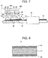
- FIG. 7 is a configuration view for illustrating a manufacturing apparatus for a vacuum heat insulating material according to a fourth embodiment of the present invention.
- the plurality of fiber-forming mechanisms 22a and 22b are arranged apart from each other in the conveyance direction of the conveyor 13. Further, in the fourth embodiment, the plurality of dispersion devices 11a, 11b, and 11c are arranged at respective positions of the fiber-forming mechanisms 22a and 22b and at a position different from those of the fiber-forming mechanisms 22a and 22b in the conveyance direction of the conveyor 13.
- the first fiber-forming mechanism 22a and the second fiber-forming mechanism 22b are arranged apart from each other in the conveyance direction of the conveyor 13. Further, in this example, the first dispersion device 11a is arranged at the same position as that of the first fiber-forming mechanism 22a in the conveyance direction of the conveyor 13. The second dispersion device 11b is arranged at the same position as that of the second fiber-forming mechanism 22b in the conveyance direction of the conveyor 13. The intermediate dispersion device 11c is arranged at the position between the first fiber-forming mechanism 22a and the second fiber-forming mechanism 22b in the conveyance direction of the conveyor 13.
- the configuration of the intermediate dispersion device 11c is the same as that of the dispersion device 11 in the first embodiment.
- the intermediate dispersion device 11c is arranged at a position outside of respective ranges of the first fiber-forming mechanism 22a and the second fiber-forming mechanism 22b. With this, the plurality of first fibers 5 dispersed in the intermediate dispersion device 11c are dropped onto the conveyor 13 without being mixed with the second fibers 6 in air above the conveyor 13.
- the other configurations of the manufacturing apparatus for a vacuum heat insulating material are the same as those of the first embodiment.
- the plurality of first fibers 5 are manufactured in advance in the same manner as in the first-fiber manufacturing step in the first embodiment.
- the plurality of first fibers 5 are supplied to each of the first dispersion device 11a, the second dispersion device 11b, and the intermediate dispersion device 11c (first-fiber manufacturing step).
- the plurality of second fibers 6 are manufactured in each of the first fiber-forming mechanism 22a and the second fiber-forming mechanism 22b in the same manner as in the second-fiber manufacturing step in the first embodiment (second-fiber manufacturing step).
- the plurality of second fibers 6 manufactured in each of the first fiber-forming mechanism 22a and the second fiber-forming mechanism 22b are supplied onto the conveyor 13 at positions respectively corresponding to the first fiber-forming mechanism 22a and the second fiber-forming mechanism 22b while being dispersed in air from the centrifugal spinner 23 of the first fiber-forming mechanism 22a. Meanwhile, the plurality of first fibers 5 are dropped while being dispersed in air from each of the first dispersion device 11a, the second dispersion device 11b, and the intermediate dispersion device 11c and supplied onto the conveyor 13 at positions respectively corresponding to the first dispersion device 11a, the second dispersion device 11b, and the intermediate dispersion device 11c.
- the first fibers 5 from each of the first dispersion device 11a and the second dispersion device 11b are tangled with the second fibers 6 to be mixed therewith, and the first fibers 5 from the intermediate dispersion device 11c are directly supplied onto the conveyor 13.
- the plurality of first fibers 5 and the plurality of second fibers 6 are mixed with each other and supplied onto the conveyor 13 at the position of the first fiber-forming mechanism 22a, only the plurality of first fibers 5 are supplied onto the conveyor 13 at the position of the intermediate dispersion device 11c, and then the plurality of first fibers 5 and the plurality of second fibers 6 are mixed with each other and further supplied onto the conveyor 13 at the position of the second fiber-forming mechanism 22b.
- the fiber layer of the first fibers 5 supplied from the intermediate dispersion device 11c is stacked on the mixed layer of the first fibers 5 and the second fibers 6 supplied from the first fiber-forming mechanism 22a and the first dispersion device 11a, and the mixed layer of the first fibers 5 and the second fibers 6 supplied from the second fiber-forming mechanism 22b and the second dispersion device 11b is stacked on the fiber layer of the first fibers 5 (fiber supply step).
- the manufacturing procedure after this is the same as that in the first embodiment.
- FIG. 8 is a vertical sectional view for illustrating the fiber body 4 manufactured by the manufacturing apparatus for a vacuum heat insulating material of FIG. 7 .
- the fiber body 4 includes the fiber layer 41 of the first fibers 5 and a pair of mixed layers 43 of the first fibers 5 and the second fibers 6.
- the fiber layer 41 and the pair of mixed layers 43 are laminated.
- the fiber layer 41 is sandwiched between the pair of mixed layers 43 in the lamination direction of the fiber layer 41 and the mixed layers 43. With this, the mixed layers 43 in the core material 2 are brought into contact with the inner surface of the outer covering material 3. Specifically, in the core material 2, portions that are brought into contact with the outer covering material 3 correspond to the mixed layers 43.
- the first dispersion device 11 a is arranged at the same position as that of the first fiber-forming mechanism 22a
- the second dispersion device 11b is arranged at the same position as that of the second fiber-forming mechanism 22b
- the intermediate dispersion device 11c is arranged between the plurality of fiber-forming mechanisms 22a and 22b. Therefore, the fiber body 4 having a configuration in which the fiber layer 41 of the first fibers 5 is sandwiched between the pair of mixed layers 43 of the first fibers 5 and the second fibers 6 can be manufactured.
- the second fibers 6 are pressed with the first fibers 5, and respective directions of the first fibers 5 and the second fibers 6 can be easily brought close to the direction orthogonal to the thickness direction of the fiber body 4 so that heat resistance can be improved.
- the heat insulating performance of the vacuum heat insulating material 1 can be further improved.
- the fiber body 4 has a configuration in which the fiber layer 41 of the first fibers 5 is sandwiched between the pair of mixed layers 43 of the first fibers 5 and the second fibers 6.
- the present invention is not limited thereto, and the fiber body 4 may have a configuration of a laminate of four or more layers in which the fiber layer 41 and the mixed layer 43 are alternately laminated.
- the fiber layer 41 of the first fibers 5 is formed of only the first fibers 5, but the second fibers 6 may be included in the fiber layer 41 of the first fibers 5.
- the content ratio of the first fibers 5 included in the fiber layer 41 of the first fibers 5 is set to be larger than the content ratio of the first fibers 5 included in the mixed layer 43.
- FIG. 9 is a configuration view for illustrating a manufacturing apparatus for a vacuum heat insulating material according to a fifth embodiment of the present invention.
- the first dispersion device 11a is removed.
- the first fiber-forming mechanism 22a and the second fiber-forming mechanism 22b are arranged apart from each other in the conveyance direction of the conveyor 13, the intermediate dispersion device 11c is arranged at a position between the first fiber-forming mechanism 22a and the second fiber-forming mechanism 22b in the conveyance direction of the conveyor 13, and the second dispersion device 11b is arranged at the same position as that of the second fiber-forming mechanism 22b in the conveyance direction of the conveyor 13.
- the other configurations of the manufacturing apparatus for a vacuum heat insulating material are the same as those of the fourth embodiment.
- the plurality of first fibers 5 are manufactured in advance in the same manner as in the first-fiber manufacturing step in the first embodiment.
- the plurality of first fibers 5 are supplied to each of the second dispersion device 11b and the intermediate dispersion device 11c (first-fiber manufacturing step).
- the plurality of second fibers 6 are manufactured in each of the first fiber-forming mechanism 22a and the second fiber-forming mechanism 22b in the same manner as in the second-fiber manufacturing step in the first embodiment (second-fiber manufacturing step).
- the plurality of second fibers 6 manufactured in each of the first fiber-forming mechanism 22a and the second fiber-forming mechanism 22b are supplied onto the conveyor 13 at positions respectively corresponding to the first fiber-forming mechanism 22a and the second fiber-forming mechanism 22b while being dispersed in air from the centrifugal spinner 23 of the first fiber-forming mechanism 22a. Meanwhile, the plurality of first fibers 5 are dropped while being dispersed in air from each of the second dispersion device 11b and the intermediate dispersion device 11c and supplied onto the conveyor 13 at positions respectively corresponding to the second dispersion device 11b and the intermediate dispersion device 11c.
- the first fibers 5 from the second dispersion device 11b are tangled with the second fibers 6 to be mixed therewith, and the second fibers 6 from the first fiber-forming mechanism 22a and the first fibers 5 from the intermediate dispersion device 11c are directly supplied onto the conveyor 13.
- the plurality of second fibers 6 are supplied onto the conveyor 13 at the position of the first fiber-forming mechanism 22a, only the plurality of first fibers 5 are supplied onto the conveyor 13 at the position of the intermediate dispersion device 11c, and then the plurality of first fibers 5 and the plurality of second fibers 6 are mixed with each other and supplied onto the conveyor 13 at the position of the second fiber-forming mechanism 22b.
- the fiber layer of the first fibers 5 supplied from the intermediate dispersion device 11c is stacked on the fiber layer of the second fibers 6 supplied from the first fiber-forming mechanism 22a, and the mixed layer of the first fibers 5 and the second fibers 6 supplied from the second fiber-forming mechanism 22b and the second dispersion device 11b is stacked on the fiber layer of the first fibers 5 (fiber supply step).
- the manufacturing procedure after this is the same as that in the first embodiment.
- FIG. 10 is a vertical sectional view for illustrating the fiber body 4 manufactured by the manufacturing apparatus for a vacuum heat insulating material of FIG. 9 .
- the fiber body 4 includes the fiber layer 41 of the first fibers 5, the fiber layer 42 of the second fibers 6, and the mixed layer 43 of the first fibers 5 and the second fibers 6.
- the fiber layer 42 of the second fibers 6, the fiber layer 41 of the first fibers 5, and the mixed layer 43 of the first fibers 5 and the second fibers 6 are successively laminated from a lower side.
- the second dispersion device 11b is arranged at the same position as that of the second fiber-forming mechanism 22b, and the intermediate dispersion device 11c is arranged between the first fiber-forming mechanism 22a and the second fiber-forming mechanism 22b. Therefore, the fiber body 4 in which the fiber layer 42 of the second fibers 6, the fiber layer 41 of the first fibers 5, and the mixed layer 43 of the first fibers 5 and the second fibers 6 are successively laminated from a lower side can be manufactured. With this, high heat resistance can be ensured in the fiber layer 41 of the first fibers 5 while the shape of the fiber body 4 is ensured by the fiber layer 42 and the mixed layer 43.
- the second fibers 6 are pressed with the first fibers 5, and respective directions of the first fibers 5 and the second fibers 6 can be easily brought close to the direction orthogonal to the thickness direction of the fiber body 4 so that heat resistance can be improved.
- the heat insulating performance of the vacuum heat insulating material 1 can be further improved.
- the fiber body 4 has a configuration of three layers in which the fiber layer 42 of the second fibers 6, the fiber layer 41 of the first fibers 5, and the mixed layer 43 of the first fibers 5 and the second fibers 6 are successively laminated.
- the present invention is not limited thereto, and the fiber body 4 may have a configuration of a laminate of four or more layers in which the fiber layer 42, the fiber layer 41, and the mixed layer 43 are successively laminated.
- the fiber layer 41 of the first fibers 5 is formed of only the first fibers 5, but the second fibers 6 may be included in the fiber layer 41 of the first fibers 5.
- the content ratio of the first fibers 5 included in the fiber layer 41 of the first fibers 5 is set to be larger than the content ratio of the first fibers 5 included in the fiber layer 42 of the second fibers 6.
- the fiber layer 42 of the second fibers 6 is formed of only the second fibers 5, but the first fibers 5 may be included in the fiber layer 42 of the second fibers 6.
- the content ratio of the second fibers 6 included in the fiber layer 42 of the second fibers 6 is set to be larger than the content ratio of the second fibers 6 included in the fiber layer 41 of the first fibers 5.
- FIG. 11 is a configuration view for illustrating a manufacturing apparatus for a vacuum heat insulating material according to a sixth embodiment of the present invention.
- the second dispersion device 11b is removed.
- the first fiber-forming mechanism 22a and the second fiber-forming mechanism 22b are arranged apart from each other in the conveyance direction of the conveyor 13, and the first dispersion device 11a is arranged at the same position as that of the first fiber-forming mechanism 22a in the conveyance direction of the conveyor 13.
- a dispersion device is not arranged at a position between the first fiber-forming mechanism 22a and the second fiber-forming mechanism 22b in the conveyance direction of the conveyor 13 and at a position of the second fiber-forming mechanism 22b in the conveyance direction of the conveyor 13.
- the other configurations of the manufacturing apparatus for a vacuum heat insulating material are the same as those of the second embodiment.
- the plurality of first fibers 5 are manufactured in advance in the same manner as in the first-fiber manufacturing step in the first embodiment.
- the plurality of first fibers 5 are supplied to the first dispersion device 11 a (first-fiber manufacturing step).
- the plurality of second fibers 6 are manufactured in each of the first fiber-forming mechanism 22a and the second fiber-forming mechanism 22b in the same manner as in the second-fiber manufacturing step in the first embodiment (second-fiber manufacturing step).
- the plurality of second fibers 6 manufactured in each of the first fiber-forming mechanism 22a and the second fiber-forming mechanism 22b are supplied onto the conveyor 13 at positions respectively corresponding to the first fiber-forming mechanism 22a and the second fiber-forming mechanism 22b while being dispersed in air from the centrifugal spinner 23 of the first fiber-forming mechanism 22a. Meanwhile, the plurality of first fibers 5 manufactured in advance are dropped while being dispersed in air from the first dispersion device 11a and supplied onto the conveyor 13 at a position corresponding to the first dispersion device 11a.
- the plurality of first fibers 5 and the plurality of second fibers 6 are supplied onto the conveyor 13 in a state of being tangled to be mixed with each other at the position corresponding to the first fiber-forming mechanism 22a, and only the plurality of second fibers 6 are supplied onto the conveyor 13 at the position corresponding to the second fiber-forming mechanism 22b.
- the plurality of second fibers 6 are further supplied onto the conveyor 13 at the position of the second fiber-forming mechanism 22b.
- the plurality of second fibers 6 supplied from the second fiber-forming mechanism 22b are stacked on the plurality of first fibers 5 and the plurality of second fibers 6 supplied from the first fiber-forming mechanism 22a and the first dispersion device 11a (fiber supply step).
- the manufacturing procedure after this is the same as that of the first embodiment.
- FIG. 12 is a vertical sectional view for illustrating the fiber body 4 manufactured by the manufacturing apparatus for a vacuum heat insulating material of FIG. 11 .
- the fiber body 4 includes the fiber layer 42 of the second fibers 6 and the mixed layer 43 of the first fibers 5 and the second fibers 6.
- the mixed layer 43 of the first fibers 5 and the second fibers 6 and the fiber layer 42 of the second fibers 6 are successively laminated from a lower side.
- the first dispersion device 11 a is arranged at the same position as that of the first fiber-forming mechanism 22a in the conveyance direction of the conveyor 13, and the second fiber-forming mechanism 22b is arranged apart from the first fiber-forming mechanism 22a in the conveyance direction of the conveyor 13. Therefore, the fiber body 4 in which the mixed layer 43 of the first fibers 5 and the second fibers 6 and the fiber layer 42 of the second fibers 6 are successively laminated from a lower side can be manufactured.
- the second fibers 6 are pressed with the first fibers 5 in the mixed layer 43 while the shape of the fiber body 4 is ensured by the fiber layer 42 and the mixed layer 43, and respective directions of the first fibers 5 and the second fibers 6 can be easily brought close to the direction orthogonal to the thickness direction of the fiber body 4.
- the heat resistance of the vacuum heat insulating material 1 can be improved, and the heat insulating performance of the vacuum heat insulating material 1 can be improved.
- the fiber body 4 has a configuration of two layers in which the mixed layer 43 of the first fibers 5 and the second fibers 6 and the fiber layer 42 of the second fibers 6 are successively laminated.
- the present invention is not limited thereto, and the fiber body 4 may have a configuration of a laminate of three or more layers in which the mixed layer 43 and the fiber layer 42 are successively laminated.
- the plurality of first fibers 5 have an average fiber diameter larger than an average fiber diameter of the plurality of second fibers 6.
- the average fiber diameter of the plurality of first fibers 5 may be the same as that of the plurality of second fibers 6.
- the average fiber diameter of the plurality of first fibers 5 may be smaller than the average fiber diameter of the plurality of second fibers 6.
- the plurality of first fibers 5 have an average fiber length larger than an average fiber length of the plurality of second fibers 6.
- the average fiber length of the plurality of first fibers 5 may be the same as that of the plurality of second fibers 6.
- the average fiber length of the plurality of first fibers 5 may be smaller than the average fiber length of the plurality of second fibers 6.
- the plurality of first fibers 5 have a Young's modulus larger than a Young's modulus of the plurality of second fibers 6.
- the Young's modulus of the plurality of first fibers 5 may be the same as that of the plurality of second fibers 6.
- the Young's modulus of the plurality of first fibers 5 may be smaller than the Young's modulus of the plurality of second fibers 6.
- the plurality of second fibers 6 having crimpability are manufactured by the centrifugation method, but the plurality of second fibers 6 may be manufactured by a flame method.
- the fiber body has a configuration in which the plurality of layers selected from the mixed layer including the first fibers 5 and the second fibers 6 mixed with each other, the fiber layer of the first fibers 5, and the fiber layer of the second fibers 6 are laminated.
- the present invention is not limited thereto, and, for example, the fiber body may have a configuration in which a plurality of kinds of mixed layers including the first fibers 5 and the second fibers 6 mixed with each other with different mixing ratios are laminated.
- the fiber body may have a configuration in which a first mixed layer including the first fibers 5 and the second fibers 6 mixed with each other at a first ratio and a second mixed layer including the first fibers 5 and the second fibers 6 mixed with each other at a second ratio different from the first ratio are laminated.
- the fiber body can be manufactured by the manufacturing apparatus illustrated in FIG. 4 .
- the fiber body may have a configuration in which a plurality of kinds of mixed layers including the first fibers 5 and the second fibers 6 mixed with each other at different mixing ratios and at least any one of the fiber layer of the first fibers 5 or the fiber layer of the second fibers 6 are laminated.
Landscapes
- Engineering & Computer Science (AREA)
- Mechanical Engineering (AREA)
- General Engineering & Computer Science (AREA)
- Thermal Insulation (AREA)
- Nonwoven Fabrics (AREA)
Abstract
Description
- The present invention relates to a vacuum heat insulating material including a core material and an outer covering material configured to accommodate the core material, a method of manufacturing a vacuum heat insulating material, and a manufacturing apparatus for a vacuum heat insulating material.
- There has hitherto been known a vacuum heat insulating material in which a core material including a plurality of laminated inorganic fiber sheets is sealed with an outer covering material under vacuum. Each of the inorganic fiber sheets is formed of curved strands and linear strands engaged with each other (see, for example, Patent Literature 1).
- Further, there has also hitherto been known the following method of manufacturing a vacuum heat insulating material. Specifically, in the method having hitherto been known, a plurality of glass chopped strands are obtained by cutting strands which are manufactured by drawing molten glass from a large number of nozzles, and a core material is obtained by laminating a plurality of pieces of non-woven fabric formed of the glass chopped strands (see, for example, Patent Literature 2).
-
- [PTL 1]
WO 2013/121992 A1 - [PTL 2]
JP 2009-162267 A - However, in the related-art vacuum heat insulating material disclosed in
Patent Literature 1, the fiber sheet in which the curved strands and the linear strands are bundled by being engaged with each other is used as the core material, and hence the curved strands cause the core material to be bulky. - With this, heat is liable to move in a thickness direction of the vacuum heat insulating material through the curved strands, and there is a risk in that the heat insulating performance of the vacuum heat insulating material may be deteriorated.
- In the related-art vacuum heat insulating material disclosed in
Patent Literature 2, it is required to bundle the plurality of glass chopped strands with a binder when non-woven fabric is manufactured. With this, the contact heat resistance between the plurality of glass chopped strands is decreased due to the binder, and there is a risk in that the heat insulating performance of the vacuum heat insulating material may be deteriorated. - The present invention has been made so as to solve the above-mentioned problems, and an object of the present invention is to obtain a vacuum heat insulating material capable of improving heat insulating performance, a method of manufacturing a vacuum heat insulating material, and a manufacturing apparatus for a vacuum heat insulating material.
- According to one embodiment of the present invention, there is provided a vacuum heat insulating material, including: a core material; and an outer covering material configured to accommodate the core material, wherein the core material includes a plurality of first fibers having linearity and a plurality of second fibers having crimpability.
- Further, according to one embodiment of the present invention, there is provided a method of manufacturing a vacuum heat insulating material, including: a fiber supply step of supplying a plurality of first fibers having linearity and a plurality of second fibers having crimpability onto a conveyor; and a compression step of compressing, after the fiber supply step, the plurality of first fibers and the plurality of second fibers on the conveyor to obtain a continuous fiber body including the plurality of first fibers and the plurality of second fibers.
- Further, according to one embodiment of the present invention, there is provided a manufacturing apparatus for a vacuum heat insulating material, including: a first-fiber manufacturing device configured to melt a first glass material and manufacture a plurality of first fibers having linearity from the melted first glass material; a second-fiber manufacturing device configured to melt a second glass material and manufacture a plurality of second fibers having crimpability from the melted second glass material; a conveyor configured to convey the plurality of first fibers and the plurality of second fibers; and a compression device configured to compress the plurality of first fibers and the plurality of second fibers on the conveyor to obtain a continuous fiber body including the plurality of first fibers and the plurality of second fibers.
- In the vacuum heat insulating material, the method of manufacturing a vacuum heat insulating material, and the manufacturing apparatus for a vacuum heat insulating material according to the present invention, the second fibers can be easily pressed with the first fibers while the deformation of the plurality of first fibers is suppressed. Thus, the direction of the plurality of first fibers can be brought close to a direction orthogonal to a thickness direction of the vacuum heat insulating material, and the direction of the plurality of second fibers can also be brought close to the direction orthogonal to the thickness direction of the vacuum heat insulating material.
- Thus, the movement of heat through the first fibers and the second fibers can be suppressed in the thickness direction of the vacuum heat insulating material. Further, when crimpability is imparted to the second fibers, the plurality of second fibers are likely to be fitted in the plurality of first fibers having linearity, with the result that the shape of the core material can be ensured without a binder. With this, the heat insulating performance of the vacuum heat insulating material can be improved.
-
- FIG. 1
- is a vertical sectional view for illustrating a vacuum heat insulating material according to a first embodiment of the present invention.
- FIG. 2
- is a partially enlarged view for illustrating a fiber body of
FIG. 1 . - FIG. 3
- is a configuration view for illustrating a manufacturing apparatus for a vacuum heat insulating material, which is configured to manufacture the fiber body of
FIG. 1 . - FIG. 4
- is a configuration view for illustrating a manufacturing apparatus for a vacuum heat insulating material according to a second embodiment of the present invention.
- FIG. 5
- is a configuration view for illustrating a manufacturing apparatus for a vacuum heat insulating material according to a third embodiment of the present invention.
- FIG. 6
- is a vertical sectional view for illustrating a fiber body manufactured by the manufacturing apparatus for a vacuum heat insulating material of
FIG. 5 . - FIG. 7
- is a configuration view for illustrating a manufacturing apparatus for a vacuum heat insulating material according to a fourth embodiment of the present invention.
- FIG. 8
- is a vertical sectional view for illustrating a fiber body manufactured by the manufacturing apparatus for a vacuum heat insulating material of
FIG. 7 . - FIG. 9
- is a configuration view for illustrating a manufacturing apparatus for a vacuum heat insulating material according to a fifth embodiment of the present invention.
- FIG. 10
- is a vertical sectional view for illustrating a fiber body manufactured by the manufacturing apparatus for a vacuum heat insulating material of
FIG. 9 . - FIG. 11
- is a configuration view for illustrating a manufacturing apparatus for a vacuum heat insulating material according to a sixth embodiment of the present invention.
- FIG. 12
- is a vertical sectional view for illustrating a fiber body manufactured by the manufacturing apparatus for a vacuum heat insulating material of
FIG. 11 . -
FIG. 1 is a vertical sectional view for illustrating a vacuum heat insulating material according to a first embodiment of the present invention. InFIG. 1 , a vacuumheat insulating material 1 includes acore material 2 and an outer coveringmaterial 3 configured to accommodate thecore material 2. Movement of heat in a thickness direction of the vacuumheat insulating material 1 is mainly largely influenced by the individual heat conduction from thecore material 2. - The
core material 2 is sealed in the outer coveringmaterial 3 under vacuum. Further, thecore material 2 includes a plurality of web-shaped fiber bodies 4 laminated in the thickness direction of the vacuumheat insulating material 1. - The outer covering
material 3 includes a first outercovering material sheet 31 and a second outer coveringmaterial sheet 32. The first outer coveringmaterial sheet 31 and the second outer coveringmaterial sheet 32 are configured to cover thecore material 2 in a state of sandwiching thecore material 2 from both sides in a lamination direction of the plurality offiber bodies 4. The outer coveringmaterial 3 has a configuration in which respective outer peripheral portions of the first outer coveringmaterial sheet 31 and the second outer coveringmaterial sheet 32 are bonded to each other. - In this example, each of the first outer
covering material sheet 31 and the second outercovering material sheet 32 has a rectangular shape, and four sides of each of the outer peripheral portions of the first outercovering material sheet 31 and the second outercovering material sheet 32 are bonded to each other. The inside of the outer coveringmaterial 3 is decompressed to a vacuum. - Further, each of the first outer covering
material sheet 31 and the second outer coveringmaterial sheet 32 is formed of a laminate film having a multilayer structure. As the laminate film, for example, an aluminum laminate sheet, in which oriented nylon (ONY), aluminum vapor-deposited polyethylene terephthalate (AL vapor-deposited PET), an aluminum foil (AL foil), and cast polypropylene (CPP) are laminated, may be used. Further, the laminate film includes, for example, an ONY layer having a film thickness of 25 µm, an AL vapor-deposited PET layer having a film thickness of 12 µm, an AL foil layer having a film thickness of 7 µm, and a CPP layer having a film thickness of 30 µm. The configuration of the laminate film is not limited thereto, and, for example, ONY, aluminum vapor-deposited polyethylene terephthalate, an aluminum vapor-deposited ethylene vinyl alcohol copolymer, CPP, and the like may be used in the laminate film. When an AL foil is not used in the configuration of the laminate film, the movement of heat through theouter covering material 3, that is, a so-called heat bridge can be suppressed. -
FIG. 2 is a partially enlarged view for illustrating thefiber body 4 ofFIG. 1 . Thefiber body 4 includes a plurality offirst fibers 5 and a plurality ofsecond fibers 6. Thefirst fibers 5 and thesecond fibers 6 are each formed of a glass material. - Each of the
first fibers 5 is a fiber having linearity. Each of thesecond fibers 6 is a fiber having crimpability. Specifically, each of thesecond fibers 6 is a curled and cotton-shaped fiber. With this, thesecond fiber 6 is more easily bent as compared to thefirst fiber 5. In this example, each of thefirst fibers 5 is a chopped glass fiber, and each of thesecond fibers 6 is glass wool. - The plurality of
first fibers 5 have an average fiber diameter larger than an average fiber diameter of the plurality ofsecond fibers 6. For example, it is desired that the plurality offirst fibers 5 have an average fiber diameter of ϕ5 µm or more, and the plurality ofsecond fibers 6 have an average fiber diameter of less than ϕ5 µm. Further, the plurality offirst fibers 5 have an average fiber length larger than an average fiber length of the plurality ofsecond fibers 6. - Further, the plurality of
first fibers 5 have a Young's modulus higher than a Young's modulus of the plurality ofsecond fibers 6. When the Young's modulus is represented by E, stress is represented by σ, and strain is represented by ε, a relationship of σ = E·ε holds. For example, when it is assumed that the fiber diameter is the same, deformation with respect to an external force is smaller as the Young's modulus is higher. - In this case, when the compression stress caused by the atmospheric pressure from outside acts on the vacuum heat insulating material, the deformation of the
second fibers 6 is larger than the deformation of thefirst fibers 5. Therefore, the straightfirst fibers 5 press thesecond fibers 6 directed in the fiber lamination direction while maintaining the shapes, and thesecond fibers 6 are easily directed in a direction orthogonal to the fiber lamination direction. - In the
fiber body 4, the plurality offirst fibers 5 and the plurality ofsecond fibers 6 are mixed with each other. Further, in thefiber body 4, the plurality ofsecond fibers 6 are tangled with the plurality offirst fibers 5. Further, in thefiber body 4, each of thefirst fibers 5 is arranged at an angle close to an angle orthogonal to the thickness direction of the vacuumheat insulating material 1. - Next, a manufacturing apparatus for the vacuum
heat insulating material 1 is described.FIG. 3 is a configuration view for illustrating a manufacturing apparatus for a vacuum heat insulating material, which is configured to manufacture thefiber body 4 ofFIG. 1 . The manufacturing apparatus for a vacuum heat insulating material includes a first-fiber manufacturing device (not shown), adispersion device 11, a second-fiber manufacturing device 12, aconveyor 13, aroller 14, and adryer 15. The first-fiber manufacturing device is configured to manufacture the plurality offirst fibers 5. - The
dispersion device 11 is configured to disperse the plurality offirst fibers 5. The second-fiber manufacturing device 12 is configured to manufacture the plurality ofsecond fibers 6. Theconveyor 13 is configured to convey the plurality offirst fibers 5 dispersed in thedispersion device 11 and the plurality of second fibers 16 manufactured in the first-fiber manufacturing device. Theroller 14 is a compression device configured to compress the plurality offirst fibers 5 and the plurality ofsecond fibers 6 on theconveyor 13 to obtain acontinuous fiber body 10. Thedryer 15 is configured to dry thecontinuous fiber body 10 compressed with theroller 14. - The first-fiber manufacturing device includes a first melting furnace, a spinning nozzle, and a cutting machine. The first melting furnace is configured to melt a first glass material. The spinning nozzle is configured to draw the melted first glass material by a drawing method to manufacture a continuous fiber. The cutting machine is configured to cut the continuous fiber to manufacture a plurality of chopped fibers so that the plurality of chopped fibers are used as the plurality of
first fibers 5. - In this example, the diameter of the continuous fiber is set to a desired diameter in advance in a range of from about ϕ6 µm to about ϕ14 µm. Further, in this example, the continuous fiber is cut to a length exceeding 8 mm, for example, a length of 50 mm with the cutting machine to manufacture the plurality of
first fibers 5. InFIG. 3 , the first melting furnace, the spinning nozzle, and the cutting machine are not illustrated. - The
dispersion device 11 is arranged above theconveyor 13. Further, thedispersion device 11 is configured to supply the plurality offirst fibers 5 onto theconveyor 13 while dispersing and dropping the plurality offirst fibers 5 manufactured in the first-fiber manufacturing device. - The second-
fiber manufacturing device 12 includes asecond melting furnace 21 and a fiber-formingmechanism 22. Thesecond melting furnace 21 is configured to melt a second glass material. The fiber-formingmechanism 22 is configured to manufacture thesecond fibers 6 from the second glass material melted in thesecond melting furnace 21 by a centrifugation method. - The fiber-forming
mechanism 22 is arranged above theconveyor 13. Further, the fiber-formingmechanism 22 is arranged at the same position as that of thedispersion device 11 in a conveyance direction of theconveyor 13. In this example, the fiber-formingmechanism 22 is arranged above thedispersion device 11. Further, the fiber-formingmechanism 22 includes acentrifugal spinner 23 and an airflow generation device 25. Thecentrifugal spinner 23 is configured to discharge the second glass material melted in thesecond melting furnace 21 with a centrifugal force. - The air
flow generation device 25 is configured to generate anair flow 24 for stretching, in an axial direction, the fiber-shaped second glass material discharged from thecentrifugal spinner 23. The first melting furnace and thesecond melting furnace 21 may be a common melting furnace or may be different from each other. Further, the first glass material and the second glass material may be the same glass material or may be different from each other. - A plurality of discharge ports are formed in an outer peripheral portion of the
centrifugal spinner 23. Thecentrifugal spinner 23 is configured to rotate to impart a centrifugal force to the second glass material melted in thesecond melting furnace 21 and discharge the melted second glass material from the plurality of discharge ports. - The air
flow generation device 25 is arranged on the periphery of thecentrifugal spinner 23. Further, the airflow generation device 25 is configured to jet anair flow 24 downwardly to theconveyor 13. The second glass material discharged from thecentrifugal spinner 23 becomes the plurality ofsecond fibers 6 having crimpability while being stretched with theair flow 24. - The plurality of
second fibers 6 are supplied onto theconveyor 13 while being dispersed and dropped from thecentrifugal spinner 23. With this, the plurality offirst fibers 5 and the plurality ofsecond fibers 6 are dropped while being mixed above theconveyor 13, and are supplied onto theconveyor 13 in a state of being mixed and tangled with each other. - The
conveyor 13 includes asuction portion 26 configured to suck theair flow 24. Theair flow 24 output from the airflow generation device 25 is sucked into thesuction portion 26 through theconveyor 13. With this, the plurality offirst fibers 5 and the plurality ofsecond fibers 6 are held on theconveyor 13, and scattering of thefirst fibers 5 and thesecond fibers 6 from theconveyor 13 is suppressed. - The
roller 14 is arranged on a downstream side in the conveyance direction of theconveyor 13 with respect to thedispersion device 11 and thecentrifugal spinner 23. Further, theroller 14 is arranged above theconveyor 13. The plurality offirst fibers 5 and the plurality ofsecond fibers 6 conveyed on theconveyor 13 are sandwiched between theconveyor 13 and theroller 14 and compressed to form thecontinuous fiber body 10. - The
dryer 15 is arranged on the downstream side in the conveyance direction of theconveyor 13 with respect to theroller 14. Theconveyor 13 penetrates through thedryer 15. With this, thecontinuous fiber body 10 is dried in thedryer 15 while being conveyed by theconveyor 13. - Next, a method of manufacturing the
core material 2 of the vacuumheat insulating material 1 is described. The plurality offirst fibers 5 are manufactured in advance by the first-fiber manufacturing device (first-fiber manufacturing step). - When the plurality of
first fibers 5 are manufactured in the first-fiber manufacturing step, the first glass material is first melted in the first melting furnace (first melting step). - After that, the melted first glass material is drawn from the spinning nozzle by the drawing method to manufacture a continuous fiber (continuous fiber manufacturing step). In this case, a plurality of continuous fibers are temporarily wound up onto a drum in a state of being bundled.
- After that, a bundle of the plurality of continuous fibers is cut to a length of, for example, 50 mm with the cutting machine while being unwound from the drum to manufacture chopped fibers. With this, the plurality of chopped fibers are obtained as the plurality of
first fibers 5. In the continuous fiber manufacturing step, the bundle of the plurality of continuous fibers may be directly cut without being wound up onto the drum to manufacture the plurality of chopped fibers (cutting step). - When the
fiber body 4 is manufactured, the plurality ofsecond fibers 6 are first manufactured by the second-fiber manufacturing device 12 (second-fiber manufacturing step). - When the plurality of
second fibers 6 are manufactured in the second-fiber manufacturing step, the second glass material is first melted in the second melting furnace 21 (second melting step). - After that, the melted second glass material is supplied to the fiber-forming
mechanism 22, and then, a plurality of pieces of glass wool are manufactured from the second glass material by the centrifugation method in the fiber-formingmechanism 22. The plurality of pieces of glass wool are used as the plurality ofsecond fibers 6. Specifically, the second glass material is discharged with a centrifugal force from the plurality of discharge ports formed in the outer peripheral portion of thecentrifugal spinner 23 while thecentrifugal spinner 23 is rotated. - The discharged second glass material is cooled while being stretched with the
air flow 24 generated in the airflow generation device 25 to form the plurality of pieces of glass wool. In this case, the fiber diameter of the second glass material is smaller by more than an order of magnitude as compared to that at the time of being discharged from thecentrifugal spinner 23. With this, the plurality of pieces of glass wool are obtained as the plurality of second fibers 6 (centrifugation step). - The plurality of
second fibers 6 are dropped to be supplied onto theconveyor 13 while being dispersed in air from thecentrifugal spinner 23. Meanwhile, the plurality offirst fibers 5 manufactured in advance are supplied to thedispersion device 11, and are dropped while being dispersed in air from thedispersion device 11 to be supplied onto theconveyor 13. The plurality offirst fibers 5 and the plurality ofsecond fibers 6 are dropped at the same position in the conveyance direction of theconveyor 13. - Therefore, the plurality of
first fibers 5 and the plurality ofsecond fibers 6 are dropped onto theconveyor 13 in a mixed state of being tangled with each other in a space above theconveyor 13, and are mixed with each other on theconveyor 13. Specifically, the plurality offirst fibers 5 and the plurality ofsecond fibers 6 are mixed with each other while being supplied onto theconveyor 13. In this case, air is sucked by thesuction portion 26, and scattering of the plurality offirst fibers 5 and the plurality ofsecond fibers 6 from theconveyor 13 is suppressed (fiber supply step). - After that, the plurality of
first fibers 5 and the plurality ofsecond fibers 6 supplied onto theconveyor 13 are conveyed by theconveyor 13, and the plurality offirst fibers 5 and the plurality ofsecond fibers 6 are compressed with theroller 14 on theconveyor 13. With this, the adhesiveness between the plurality offirst fibers 5 and the plurality ofsecond fibers 6 is enhanced, and thecontinuous fiber body 10 is obtained (compression step). - Thereafter, the
continuous fiber body 10 is caused to pass through thedryer 15 while being conveyed on theconveyor 13, to thereby remove, for example, moisture of the continuous fiber body 10 (drying step). - After that, the
continuous fiber body 10 is cut to a predetermined dimension to manufacture thefiber body 4. In this case, thecontinuous fiber body 10 dried by thedryer 15 may be temporarily wound into a roll shape, and then, the roll-shapedcontinuous fiber body 10 may be unwound to be cut. Alternatively, thecontinuous fiber body 10 may be directly cut at the most downstream position of the conveyor 13 (cutting step). - Thereafter, the
core material 2 is manufactured from the plurality offiber bodies 4. Specifically, the plurality offiber bodies 4 are laminated, and then, the laminated plurality offiber bodies 4 are cut in conformity with the size of thecore material 2 to manufacture thecore material 2. The size of each of thefiber bodies 4 is set in consideration of the strain of thefiber body 4 caused by a pressure difference between the atmospheric pressure and the vacuum, which is dependent on vacuum sealing at the time of manufacturing of the vacuumheat insulating material 1. - The
core material 2 may be manufactured by cutting the plurality offiber bodies 4 in advance in conformity with the size of thecore material 2 and laminating the plurality offiber bodies 4 in conformity with the size of thecore material 2. Further, thefiber body 4 that is a single body may be used as thecore material 2 instead of laminating the plurality of fiber bodies 4 (core material manufacturing step). - Next, a method of manufacturing the vacuum
heat insulating material 1 is described. When theouter covering material 3 is manufactured, a continuous outer covering material sheet wound into a roll shape is first cut to manufacture the first outercovering material sheet 31 having a rectangular shape and the second outer coveringmaterial sheet 32 having a rectangular shape, and then, the first outercovering material sheet 31 and the second outer coveringmaterial sheet 32 are stacked on one another. - After that, the first outer
covering material sheet 31 and the second outer coveringmaterial sheet 32 are bonded to each other through heat seal joining at positions of two sides along a widthwise direction and at a position of one side along a lengthwise direction of four sides of the stacked first outercovering material sheet 31 and the second outer coveringmaterial sheet 32. - Thereafter, the first outer
covering material sheet 31 and the second outer coveringmaterial sheet 32 are cut together so that the dimension in the widthwise direction has a set value, to thereby manufacture theouter covering material 3 having a bag shape with an opening. In the bag-shapedouter covering material 3, of four sides of the rectangle of the stacked first outercovering material sheet 31 and the second outer coveringmaterial sheet 32, two sides along the widthwise direction and one side along the lengthwise direction are joined to each other, and the remaining one side along the lengthwise direction is not joined. - After the bag-shaped
outer covering material 3 is manufactured, thecore material 2 is inserted into the bag-shapedouter covering material 3 through the opening of theouter covering material 3. After that, the bag-shapedouter covering material 3 accommodating thecore material 2 is placed in a vacuum chamber, and the inside of the vacuum chamber is decompressed. - In this case, the inside of the vacuum chamber is decompressed so as to have a vacuum degree within a range of, for example, from 0.1 Pa to 3 Pa. With this, the bag-shaped
outer covering material 3 accommodating thecore material 2 is subjected to decompression processing. In this case, the thickness of thecore material 2 is reduced to about 1/5 to about 1/10 as compared to the thickness given before the decompression processing. - After that, in a state in which the bag-shaped
outer covering material 3 accommodating thecore material 2 is subjected to the decompression processing, the remaining one side, which is not joined, in the bag-shapedouter covering material 3 is subjected to heat seal joining. With this, theouter covering material 3, in which the respective outer peripheral portions of the first outercovering material sheet 31 and the second outer coveringmaterial sheet 32 are bonded to each other, is completed. Further, with this, the vacuumheat insulating material 1, in which thecore material 2 is sealed in theouter covering material 3 in vacuum, is completed. After that, the inside of the vacuum chamber is returned to the atmospheric pressure, and the vacuumheat insulating material 1 is taken out from the vacuum chamber. - When, for example, moisture remains in the
core material 2 in a state in which thecore material 2 is sealed in theouter covering material 3 in vacuum, gas is generated from thecore material 2 in theouter covering material 3, and there is a risk in that the vacuum degree in theouter covering material 3 may decrease. Thus, it is desired that thecore material 2 be dried until immediately before the decompression processing is performed in the vacuum chamber. - Further, when the bag-shaped
outer covering material 3 accommodating thecore material 2 is placed in the vacuum chamber, an adsorbent for adsorbing moisture and gas may be inserted into theouter covering material 3 as necessary. As the adsorbent, for example, a single substance or a complex of calcium oxide, zeolite, a barium lithium alloy, and the like is used. With this, the adsorbent can be caused to adsorb moisture and air in theouter covering material 3, and the vacuum state in theouter covering material 3 of the vacuumheat insulating material 1 can be improved. - In the vacuum
heat insulating material 1 in this example, thefirst fibers 5 and thesecond fibers 6 are present in about 10 % of thecore material 2 in a volume ratio, and a vacuum space is ensured in about 90 % of thecore material 2 in a volume ratio. Thus, the vacuum space is ensured in about 90 % of thecore material 2, and hence high heat insulating performance of the vacuumheat insulating material 1 is ensured. - In the above-mentioned vacuum
heat insulating material 1, when thecore material 2 accommodated in theouter covering material 3 includes the plurality offirst fibers 5 having linearity and the plurality of cotton-shapedsecond fibers 6 having crimpability, thesecond fibers 6 having crimpability are more easily deformed with respect to an external force, as compared to thefirst fibers 5. - With this, in a compressed state in the
outer covering material 3, thesecond fibers 6 can be easily pressed with thefirst fibers 5 while the deformation of the plurality offirst fibers 5 is suppressed, with the result that thesecond fibers 6 directed in the thickness direction of the vacuumheat insulating material 1 can be easily flattened. Thus, the direction of the plurality offirst fibers 6 can be brought close to a direction orthogonal to the thickness direction of the vacuumheat insulating material 1, and the direction of the plurality ofsecond fibers 6 can also be brought close to the direction orthogonal to the thickness direction of the vacuumheat insulating material 1. - Thus, the movement of heat through the
first fibers 5 and thesecond fibers 6 can be suppressed in the thickness direction of the vacuumheat insulating material 1. Further, when crimpability is imparted to thesecond fibers 6, the plurality ofsecond fibers 6 are likely to be fitted in the plurality offirst fibers 5 having linearity, with the result that the shape of thecore material 2 can be ensured without a binder. With this, the heat insulating performance of the vacuumheat insulating material 1 can be improved. - Further, in the above-mentioned manufacturing apparatus for the vacuum
heat insulating material 1, the plurality offirst fibers 5 having linearity and the plurality ofsecond fibers 6 having crimpability are conveyed by theconveyor 13, and the plurality offirst fibers 5 and the plurality ofsecond fibers 6 are compressed with theroller 14 on theconveyor 13, to thereby obtain thecontinuous fiber body 10. Therefore, thecontinuous fiber body 10 serving as a raw material for thecore material 2 can be easily manufactured, and the vacuumheat insulating material 1 capable of improving the heat insulating performance can be easily manufactured. Further, thecontinuous fiber body 10 can be manufactured without use of a paper-making method or the like. Therefore, heating energy for removing moisture from thecontinuous fiber body 10 can be significantly decreased, and cost can be reduced. - Further, the manufacturing apparatus for the vacuum
heat insulating material 1 includes the fiber-formingmechanism 22 configured to manufacture the plurality ofsecond fibers 6 from the melted second glass material by the centrifugation method, and hence the plurality ofsecond fibers 6 having crimpability can be easily manufactured. - Further, in the above-mentioned method of manufacturing the vacuum
heat insulating material 1, the plurality offirst fibers 5 having linearity and the plurality ofsecond fibers 6 having crimpability are conveyed by theconveyor 13, and the plurality offirst fibers 5 and the plurality ofsecond fibers 6 are compressed on theconveyor 13. - Therefore, the
continuous fiber body 10 serving as a raw material for thecore material 2 can be easily manufactured, and the vacuumheat insulating material 1 capable of improving the heat insulating performance can be easily manufactured. Further, thecontinuous fiber body 10 can be manufactured without use of a paper-making method or the like. Therefore, heating energy for removing moisture from thecontinuous fiber body 10 can be significantly decreased, and cost can be reduced. - Further, in the method of manufacturing the vacuum
heat insulating material 1, after the continuous fiber is manufactured from the melted first glass material by the drawing method, the manufactured continuous fiber is cut to manufacture the chopped fibers so that the chopped fibers are used as the plurality offirst fibers 5. Therefore, the plurality offirst fibers 5 can be easily manufactured. - Moreover, in the method of manufacturing the vacuum
heat insulating material 1, the glass wool is manufactured from the melted second glass material by the centrifugation method so that the glass wool is used as the plurality ofsecond fibers 6. Therefore, the plurality ofsecond fibers 6 can be easily manufactured. - Further, in the method of manufacturing the vacuum
heat insulating material 1, the plurality offirst fibers 5 and the plurality ofsecond fibers 6 are mixed with each other while the plurality offirst fibers 5 and the plurality ofsecond fibers 6 are supplied onto theconveyor 13. Therefore, the plurality ofsecond fibers 6 can be easily tangled with the plurality offirst fibers 5. With this, the binding force between the plurality offirst fibers 5 and the plurality ofsecond fibers 6 can be easily increased, and the shape of thecore material 2 can be more reliably ensured without use of a binder. - Further, in the method of manufacturing the vacuum
heat insulating material 1, the plurality offirst fibers 5 and the plurality ofsecond fibers 6 are mixed with each other in a space above theconveyor 13, and hence the plurality ofsecond fibers 6 can be more reliably tangled with the plurality offirst fibers 5. With this, the binding force between the plurality offirst fibers 5 and the plurality ofsecond fibers 6 can be more reliably increased, and the shape of thecore material 2 can be more reliably ensured without use of a binder. - Moreover, the plurality of
first fibers 5 have an average fiber diameter larger than an average fiber diameter of the plurality ofsecond fibers 6. Therefore, thesecond fibers 6 can be more easily deformed as compared to thefirst fibers 5, and thesecond fibers 6 can be more easily pressed with thefirst fibers 5. With this, the direction of the plurality ofsecond fibers 6, as well as the direction of the plurality offirst fibers 6 can be further brought close to the direction orthogonal to the thickness direction of the vacuumheat insulating material 1. - Further, the plurality of
second fibers 6 have a smaller average fiber diameter, and hence the heat transfer amount of thesecond fibers 6 themselves can also be reduced. Because of the foregoing, the movement of heat through thefirst fibers 5 and thesecond fibers 6 can be further suppressed in the thickness direction of the vacuumheat insulating material 1, and the heat insulating performance of the vacuumheat insulating material 1 can be further improved. - Also, the plurality of
first fibers 5 have an average fiber length larger than an average fiber length of the plurality ofsecond fibers 6, and hence thesecond fibers 6 can be more easily pressed with thefirst fibers 5. Further, a heat transfer path through the plurality ofsecond fibers 6 is formed into small segments. Thus, the movement of heat through thefirst fibers 5 and thesecond fibers 6 can be further suppressed in the thickness direction of the vacuumheat insulating material 1, and the heat insulating performance of the vacuumheat insulating material 1 can be further improved. - Furthermore, the plurality of
second fibers 6 have a Young's modulus lower than a Young's modulus of the plurality offirst fibers 5, and hence thesecond fibers 6 are more easily deformed as compared to thefirst fibers 5. With this, through pressing of the plurality ofsecond fibers 6 directed in the thickness direction of the vacuumheat insulating material 1 with thefirst fibers 5, the direction of thesecond fibers 6 can be more easily brought close to the direction orthogonal to the thickness direction of the vacuumheat insulating material 1 while the deformation of the plurality offirst fibers 5 is suppressed. Thus, the heat insulating performance of the vacuumheat insulating material 1 can be more easily improved. - The magnitude of a Young's modulus E can be adjusted by changing the composition of the glass material. For example, in the case of a fiber formed of a glass material containing Al2O3, as the content of Al2O3 is increased, the fiber has a higher Young's modulus E. Therefore, for example, when the content of Al2O3 contained in the first glass material forming the
first fibers 5 is set to be higher than the content of Al2O3 contained in the second glass material forming thesecond fibers 6, the Young's modulus of the plurality offirst fibers 5 can be set to be higher than the Young's modulus of the plurality ofsecond fibers 6. - Further, when the Young's modulus is represented by E, and the average fiber diameter is represented by d, it is desired that the
first fibers 5 have a value of (π·d2·E)/4 larger than a value of (π·d2·E)/4 of thesecond fibers 6 from the viewpoint of fiber stiffness. - Next, in order to verify the effects of the vacuum heat insulating material according to the first embodiment, the vacuum heat insulating material according to the first embodiment and a vacuum heat insulating material according to Comparative Example to be compared to the first embodiment were respectively manufactured, and the heat conductivity of the vacuum heat insulating material according to the first embodiment and the heat conductivity of the vacuum heat insulating material according to Comparative Example were measured.
- In the vacuum heat insulating material according to the first embodiment, a continuous fiber having an average diameter of ϕ6 µm was manufactured by drawing the first glass material having a composition of E glass from a spinning nozzle by the drawing method, and the manufactured continuous fiber was cut to an average fiber length of about 10 mm, to thereby manufacture the plurality of
first fibers 5. - Further, in the vacuum heat insulating material according to the first embodiment, glass wool having an average diameter of about ϕ4 µm was manufactured as the plurality of
second fibers 6 from the second glass material having a composition of C glass by the centrifugation method. Further, in the vacuum heat insulating material according to the first embodiment, the plurality offirst fibers 5 were mixed with thesecond fibers 6 in a process of supplying the manufacturedsecond fibers 6 onto theconveyor 13, to thereby manufacture a plurality of mixed layers in which the plurality offirst fibers 5 and the plurality ofsecond fibers 6 were mixed with each other. - A laminate in which four mixed layers were laminated was used as the
core material 2. Further, in the vacuum heat insulating material according to the first embodiment, the weight ratio between thefirst fibers 5 and thesecond fibers 6 in thecore material 2 was set to about 7:3. Meanwhile, in Comparative Example, the vacuum heat insulating material in which a laminate including only the plurality of second fibers was used as the core material was manufactured under the same condition as that of the first embodiment. - As a result of measurement of the heat conductivity of the vacuum heat insulating material according to the first embodiment and the heat conductivity of the vacuum heat insulating material according to Comparative Example, the heat conductivity of the vacuum heat insulating material according to the first embodiment was 0.0013 W/(m·K), and the heat conductivity of the vacuum heat insulating material according to Comparative Example was 0.0017 W/(m·K).
- According to this verification, the heat conductivity being an indicator for indicating the heat insulating performance was reduced by about 24 % in the vacuum heat insulating material according to the first embodiment as compared to the heat conductivity of the vacuum heat insulating material according to Comparative Example.
-
FIG. 4 is a configuration view for illustrating a manufacturing apparatus for a vacuum heat insulating material according to a second embodiment of the present invention. In the second embodiment, a plurality of fiber-formingmechanisms conveyor 13, and a plurality ofdispersion devices conveyor 13. - The number of the fiber-forming
mechanisms dispersion devices dispersion devices mechanisms conveyor 13. - In this example, the first fiber-forming
mechanism 22a and the second fiber-formingmechanism 22b are arranged apart from each other in the conveyance direction of theconveyor 13. Further, in this example, thefirst dispersion device 11a is arranged at the same position as that of the first fiber-formingmechanism 22a in the conveyance direction of theconveyor 13, and thesecond dispersion device 11b is arranged at the same position as that of the second fiber-formingmechanism 22b in the conveyance direction of theconveyor 13. - The second fiber-forming
mechanism 22b is arranged on a downstream side in the conveyance direction of theconveyor 13 with respect to the first fiber-formingmechanism 22a, that is, on theroller 14 side. Each configuration of the first fiber-formingmechanism 22a and the second fiber-formingmechanism 22b is the same as that of the fiber-formingmechanism 22 in the first embodiment. The melted second glass material is supplied to each of the first fiber-formingmechanism 22a and the second fiber-formingmechanism 22b from the commonsecond melting furnace 21. - Further, the
first dispersion device 11a is arranged below the first fiber-formingmechanism 22a, and thesecond dispersion device 11b is arranged below the second fiber-formingmechanism 22b. Each configuration of thefirst dispersion device 11a and thesecond dispersion device 11b is the same as that of thedispersion device 11 in the first embodiment. The other configurations of the manufacturing apparatus for a vacuum heat insulating material are the same as those of the first embodiment. - Next, a method of manufacturing the
core material 2 of the vacuumheat insulating material 1 is described. First, the plurality offirst fibers 5 are manufactured in advance in the same manner as in the first-fiber manufacturing step in the first embodiment. The plurality offirst fibers 5 are supplied to each of thefirst dispersion device 11a and thesecond dispersion device 11b (first-fiber manufacturing step). - When the
fiber body 4 is manufactured, the plurality ofsecond fibers 6 are manufactured in each of the first fiber-formingmechanism 22a and the second fiber-formingmechanism 22b in the same manner as in the second-fiber manufacturing step in the first embodiment (second-fiber manufacturing step). - The plurality of
second fibers 6 manufactured in each of the first fiber-formingmechanism 22a and the second fiber-formingmechanism 22b are supplied onto theconveyor 13 at positions respectively corresponding to the first fiber-formingmechanism 22a and the second fiber-formingmechanism 22b while being dispersed in air from thecentrifugal spinner 23 of the first fiber-formingmechanism 22a. Meanwhile, the plurality offirst fibers 5 manufactured in advance are dropped while being dispersed in air from each of thefirst dispersion device 11 a and thesecond dispersion device 11b and supplied onto theconveyor 13 at positions respectively corresponding to thefirst dispersion device 11a and thesecond dispersion device 11b. - With this, the plurality of
first fibers 5 and the plurality ofsecond fibers 6 are supplied to different positions on theconveyor 13 in a state of being tangled to be mixed with each other. Specifically, in the conveyance direction of theconveyor 13, the plurality offirst fibers 5 and the plurality ofsecond fibers 6 are supplied onto theconveyor 13 at the positions of the first fiber-formingmechanism 22a and thefirst dispersion device 11a, and then further supplied onto theconveyor 13 at the positions of the second fiber-formingmechanism 22b and thesecond dispersion device 11b. - With this, on the
conveyor 13, the plurality offirst fibers 5 and the plurality ofsecond fibers 6 supplied from the second fiber-formingmechanism 22b and thesecond dispersion device 11b are stacked on the plurality offirst fibers 5 and the plurality ofsecond fibers 6 supplied from the first fiber-formingmechanism 22a and thefirst dispersion device 11a (fiber supply step). The manufacturing procedure after this is the same as that of the first embodiment. - In the
fiber body 4 manufactured by the manufacturing method in the second embodiment, the mixed layers of the plurality offirst fibers 5 and the plurality ofsecond fibers 6 are formed in two stages. - In the above-mentioned method of manufacturing a vacuum heat insulating material, the plurality of
first fibers 5 are supplied onto theconveyor 13 from each of the plurality ofdispersion devices conveyor 13, and the plurality ofsecond fibers 6 are supplied onto theconveyor 13 from the plurality of fiber-formingmechanisms dispersion devices conveyor 13. - Therefore, the number of the mixed layers of the plurality of
first fibers 5 and the plurality ofsecond fibers 6 in thefiber body 4 can be increased to a plurality of stages as compared to thefiber body 4 in the first embodiment. With this, the plurality offirst fibers 5 and the plurality ofsecond fibers 6 can be more finely mixed with each other, and the binding force of the plurality offirst fibers 5 and the plurality ofsecond fibers 6 can be further increased. Further, the number of the mixed layers of the plurality offirst fibers 5 and the plurality ofsecond fibers 6 is increased. - Therefore, the thickness per layer of the mixed layers in the
fiber body 4 can be reduced, and the direction of thefirst fibers 5 and the direction of thesecond fibers 6 can be more reliably brought close to the direction orthogonal to the thickness direction of the vacuumheat insulating material 1. With this, the heat insulating performance of the vacuumheat insulating material 1 can be more reliably improved. - Further, in the second embodiment, when the supply amount of the
first fibers 5 supplied from thefirst dispersion device 11a, the supply amount of thefirst fibers 5 supplied from thesecond dispersion device 11b, and the supply amount of thefirst fibers 5 supplied from thedispersion device 11 in the first embodiment are the same, and the supply amount of thesecond fibers 6 supplied from the first fiber-formingmechanism 22a, the supply amount of thesecond fibers 6 supplied from the second fiber-formingmechanism 22b, and the supply amount of thesecond fibers 6 supplied from the fiber-formingmechanism 22 in the first embodiment are the same, thefiber body 4 having a thickness that is twice the thickness of thefiber body 4 in the first embodiment can be manufactured. In this case, the number of lamination of thefiber body 4 forming thecore material 2 can be halved without deteriorating the heat insulating performance of thecore material 2, and the number of components and cost can be reduced. - In the above-mentioned example, the number of the fiber-forming
mechanisms dispersion devices conveyor 13, and the dispersion devices are arranged at the same positions as those of the fiber-forming mechanisms in the conveyance direction of theconveyor 13. -
FIG. 5 is a configuration view for illustrating a manufacturing apparatus for a vacuum heat insulating material according to a third embodiment of the present invention. In the third embodiment, the plurality of fiber-formingmechanisms conveyor 13. Further, in the third embodiment, anintermediate dispersion device 11c is arranged at a position different from those of the fiber-formingmechanisms conveyor 13. - In this example, the first fiber-forming
mechanism 22a and the second fiber-formingmechanism 22b are arranged apart from each other in the conveyance direction of theconveyor 13. Further, in this example, theintermediate dispersion device 11c is arranged at a position between the first fiber-formingmechanism 22a and the second fiber-formingmechanism 22b in the conveyance direction of theconveyor 13. - The second fiber-forming
mechanism 22b is arranged on the downstream side in the conveyance direction of theconveyor 13 with respect to the first fiber-formingmechanism 22a, that is, on theroller 14 side. Each configuration of the first fiber-formingmechanism 22a and the second fiber-formingmechanism 22b is the same as that of the fiber-formingmechanism 22 in the first embodiment. The melted second glass material is supplied to each of the first fiber-formingmechanism 22a and the second fiber-formingmechanism 22b from the commonsecond melting furnace 21. - The configuration of the
intermediate dispersion device 11c is the same as that of thedispersion device 11 in the first embodiment. When viewed from above, theintermediate dispersion device 11c is arranged at a position outside of respective ranges of the first fiber-formingmechanism 22a and the second fiber-formingmechanism 22b. With this, the plurality offirst fibers 5 dispersed in theintermediate dispersion device 11 c are dropped onto theconveyor 13 without being mixed with thesecond fibers 6 in air above theconveyor 13. The other configurations of the manufacturing apparatus for a vacuum heat insulating material are the same as those of the first embodiment. - Next, a method of manufacturing the
core material 2 of the vacuumheat insulating material 1 is described. First, the plurality offirst fibers 5 are manufactured in advance in the same manner as in the first-fiber manufacturing step in the first embodiment. The plurality offirst fibers 5 are supplied to theintermediate dispersion device 11c (first-fiber manufacturing step). - When the
fiber body 4 is manufactured, the plurality ofsecond fibers 6 are manufactured in each of the first fiber-formingmechanism 22a and the second fiber-formingmechanism 22b in the same manner as in the second-fiber manufacturing step in the first embodiment (second-fiber manufacturing step). - The plurality of
second fibers 6 manufactured in each of the first fiber-formingmechanism 22a and the second fiber-formingmechanism 22b are supplied onto theconveyor 13 at positions respectively corresponding to the first fiber-formingmechanism 22a and the second fiber-formingmechanism 22b while being dispersed in air from thecentrifugal spinner 23 of the first fiber-formingmechanism 22a. - Meanwhile, the plurality of
first fibers 5 manufactured in advance are dropped while being dispersed in air from theintermediate dispersion device 11c and supplied onto theconveyor 13 at positions respectively corresponding to theintermediate dispersion device 11 c. Thus, in the conveyance direction of theconveyor 13, after the plurality ofsecond fibers 6 are supplied onto theconveyor 13 at the position of the first fiber-formingmechanism 22a, the plurality offirst fibers 5 are supplied onto theconveyor 13 at the position of theintermediate dispersion device 11c, and then the plurality ofsecond fibers 6 are further supplied onto theconveyor 13 at the position of the second fiber-formingmechanism 22b. - With this, on the
conveyor 13, a fiber layer of thefirst fibers 5 supplied from theintermediate dispersion device 11c is stacked on a fiber layer of thesecond fibers 6 supplied from the first fiber-formingmechanism 22a, and a fiber layer of thesecond fibers 6 supplied from the second fiber-formingmechanism 22b is stacked on a fiber layer of the first fibers 5 (fiber supply step). The manufacturing procedure after this is the same as that in the first embodiment. -
FIG. 6 is a vertical sectional view for illustrating thefiber body 4 manufactured by the manufacturing apparatus for a vacuum heat insulating material ofFIG. 5 . Thefiber body 4 includes afiber layer 41 of thefirst fibers 5 and a pair of fiber layers 42 of thesecond fibers 6. In thefiber body 4, thefiber layer 41 and the pair of fiber layers 42 are laminated. Thefiber layer 41 is sandwiched between the pair of fiber layers 41 in the lamination direction of the fiber layers 41 and 42. With this, the fiber layers 42 of thesecond fibers 6 in thecore material 2 are brought into contact with an inner surface of theouter covering material 3. Specifically, in thecore material 2, portions that are brought into contact with theouter covering material 3 correspond to the fiber layers 42 of thesecond fibers 6. - In the above-mentioned method of manufacturing a vacuum heat insulating material, the
intermediate dispersion device 11c is arranged between the plurality of fiber-formingmechanisms conveyor 13, and hence thefiber body 4 having a configuration in which thefiber layer 41 of thefirst fibers 5 is sandwiched between the pair of fiber layers 42 of thesecond fibers 6 can be manufactured. With this, high heat resistance can be ensured in thefiber layer 41 of thefirst fibers 5 while the shape of thefiber body 4 is ensured by the fiber layers 42 of thesecond fibers 6. Thus, the heat insulating performance of the vacuumheat insulating material 1 can be improved. - From the viewpoint of the heat insulating performance of the vacuum
heat insulating material 1, it is preferred that the thickness of thefiber layer 42 of thesecond fibers 6 be smaller because the heat resistance of thefiber layer 41 of thefirst fibers 5 is large. Thus, it is preferred that the thickness of thefiber layer 41 of thefirst fibers 5 be set to 50 % or more of the thickness of theentire fiber body 4. - Further, in the above-mentioned example, the
fiber body 4 has a configuration in which thefiber layer 42 of thesecond fibers 6, thefiber layer 41 of thefirst fibers 5, and thefiber layer 42 of thesecond fibers 6 are successively stacked on one another. However, thefiber body 4 may have a configuration in which thefiber layer 41 of thefirst fibers 5, thefiber layer 42 of thesecond fibers 6, and thefiber layer 41 of thefirst fibers 5 are successively stacked on one another. In this case, the first dispersion device configured to manufacture thefirst fibers 5, the fiber-forming mechanism configured to manufacture thesecond fibers 6, and the second dispersion device configured to manufacture thefirst fibers 5 are arranged in the order of the first dispersion device, the fiber-forming mechanism, and the second dispersion device in the conveyance direction of theconveyor 13. - With this, in the conveyance direction of the
conveyor 13, after the plurality offirst fibers 5 are supplied onto theconveyor 13 at the position of the first dispersion device, the plurality ofsecond fibers 6 are supplied onto theconveyor 13 at the position of the fiber-forming mechanism, and the plurality offirst fibers 5 are further supplied onto theconveyor 13 at the position of the second dispersion device. - Further, in the above-mentioned example, the
fiber body 4 has a configuration in which thefiber layer 41 of thefirst fibers 5 is sandwiched between the pair of fiber layers 42 of thesecond fibers 6. However, the present invention is not limited thereto, and thefiber body 4 may have a configuration of a fiber layer laminate of four or more layers in which thefiber layer 41 of thefirst fibers 5 and thefiber layer 42 of thesecond fibers 6 are alternately laminated. -
FIG. 7 is a configuration view for illustrating a manufacturing apparatus for a vacuum heat insulating material according to a fourth embodiment of the present invention. In the fourth embodiment, the plurality of fiber-formingmechanisms conveyor 13. Further, in the fourth embodiment, the plurality ofdispersion devices mechanisms mechanisms conveyor 13. - In this example, the first fiber-forming
mechanism 22a and the second fiber-formingmechanism 22b are arranged apart from each other in the conveyance direction of theconveyor 13. Further, in this example, thefirst dispersion device 11a is arranged at the same position as that of the first fiber-formingmechanism 22a in the conveyance direction of theconveyor 13. Thesecond dispersion device 11b is arranged at the same position as that of the second fiber-formingmechanism 22b in the conveyance direction of theconveyor 13. Theintermediate dispersion device 11c is arranged at the position between the first fiber-formingmechanism 22a and the second fiber-formingmechanism 22b in the conveyance direction of theconveyor 13. - The configuration of the
intermediate dispersion device 11c is the same as that of thedispersion device 11 in the first embodiment. When viewed from above, theintermediate dispersion device 11c is arranged at a position outside of respective ranges of the first fiber-formingmechanism 22a and the second fiber-formingmechanism 22b. With this, the plurality offirst fibers 5 dispersed in theintermediate dispersion device 11c are dropped onto theconveyor 13 without being mixed with thesecond fibers 6 in air above theconveyor 13. The other configurations of the manufacturing apparatus for a vacuum heat insulating material are the same as those of the first embodiment. - Next, a method of manufacturing the
core material 2 of the vacuumheat insulating material 1 is described. First, the plurality offirst fibers 5 are manufactured in advance in the same manner as in the first-fiber manufacturing step in the first embodiment. The plurality offirst fibers 5 are supplied to each of thefirst dispersion device 11a, thesecond dispersion device 11b, and theintermediate dispersion device 11c (first-fiber manufacturing step). - When the
fiber body 4 is manufactured, the plurality ofsecond fibers 6 are manufactured in each of the first fiber-formingmechanism 22a and the second fiber-formingmechanism 22b in the same manner as in the second-fiber manufacturing step in the first embodiment (second-fiber manufacturing step). - The plurality of
second fibers 6 manufactured in each of the first fiber-formingmechanism 22a and the second fiber-formingmechanism 22b are supplied onto theconveyor 13 at positions respectively corresponding to the first fiber-formingmechanism 22a and the second fiber-formingmechanism 22b while being dispersed in air from thecentrifugal spinner 23 of the first fiber-formingmechanism 22a. Meanwhile, the plurality offirst fibers 5 are dropped while being dispersed in air from each of thefirst dispersion device 11a, thesecond dispersion device 11b, and theintermediate dispersion device 11c and supplied onto theconveyor 13 at positions respectively corresponding to thefirst dispersion device 11a, thesecond dispersion device 11b, and theintermediate dispersion device 11c. - Thus, the
first fibers 5 from each of thefirst dispersion device 11a and thesecond dispersion device 11b are tangled with thesecond fibers 6 to be mixed therewith, and thefirst fibers 5 from theintermediate dispersion device 11c are directly supplied onto theconveyor 13. Specifically, in the conveyance direction of theconveyor 13, after the plurality offirst fibers 5 and the plurality ofsecond fibers 6 are mixed with each other and supplied onto theconveyor 13 at the position of the first fiber-formingmechanism 22a, only the plurality offirst fibers 5 are supplied onto theconveyor 13 at the position of theintermediate dispersion device 11c, and then the plurality offirst fibers 5 and the plurality ofsecond fibers 6 are mixed with each other and further supplied onto theconveyor 13 at the position of the second fiber-formingmechanism 22b. - With this, on the
conveyor 13, the fiber layer of thefirst fibers 5 supplied from theintermediate dispersion device 11c is stacked on the mixed layer of thefirst fibers 5 and thesecond fibers 6 supplied from the first fiber-formingmechanism 22a and thefirst dispersion device 11a, and the mixed layer of thefirst fibers 5 and thesecond fibers 6 supplied from the second fiber-formingmechanism 22b and thesecond dispersion device 11b is stacked on the fiber layer of the first fibers 5 (fiber supply step). The manufacturing procedure after this is the same as that in the first embodiment. -
FIG. 8 is a vertical sectional view for illustrating thefiber body 4 manufactured by the manufacturing apparatus for a vacuum heat insulating material ofFIG. 7 . Thefiber body 4 includes thefiber layer 41 of thefirst fibers 5 and a pair ofmixed layers 43 of thefirst fibers 5 and thesecond fibers 6. In thefiber body 4, thefiber layer 41 and the pair ofmixed layers 43 are laminated. - The
fiber layer 41 is sandwiched between the pair ofmixed layers 43 in the lamination direction of thefiber layer 41 and the mixed layers 43. With this, themixed layers 43 in thecore material 2 are brought into contact with the inner surface of theouter covering material 3. Specifically, in thecore material 2, portions that are brought into contact with theouter covering material 3 correspond to the mixed layers 43. - In the above-mentioned method of manufacturing a vacuum heat insulating material, in the conveyance direction of the
conveyor 13, thefirst dispersion device 11 a is arranged at the same position as that of the first fiber-formingmechanism 22a, thesecond dispersion device 11b is arranged at the same position as that of the second fiber-formingmechanism 22b, and theintermediate dispersion device 11c is arranged between the plurality of fiber-formingmechanisms fiber body 4 having a configuration in which thefiber layer 41 of thefirst fibers 5 is sandwiched between the pair ofmixed layers 43 of thefirst fibers 5 and thesecond fibers 6 can be manufactured. - With this, high heat resistance can be ensured in the
fiber layer 41 of thefirst fibers 5 while the shape of thefiber body 4 is ensured by the mixed layers 43. Further, also in themixed layer 43, thesecond fibers 6 are pressed with thefirst fibers 5, and respective directions of thefirst fibers 5 and thesecond fibers 6 can be easily brought close to the direction orthogonal to the thickness direction of thefiber body 4 so that heat resistance can be improved. Thus, the heat insulating performance of the vacuumheat insulating material 1 can be further improved. - In the above-mentioned example, the
fiber body 4 has a configuration in which thefiber layer 41 of thefirst fibers 5 is sandwiched between the pair ofmixed layers 43 of thefirst fibers 5 and thesecond fibers 6. However, the present invention is not limited thereto, and thefiber body 4 may have a configuration of a laminate of four or more layers in which thefiber layer 41 and themixed layer 43 are alternately laminated. - Further, in the above-mentioned example, the
fiber layer 41 of thefirst fibers 5 is formed of only thefirst fibers 5, but thesecond fibers 6 may be included in thefiber layer 41 of thefirst fibers 5. In this case, the content ratio of thefirst fibers 5 included in thefiber layer 41 of thefirst fibers 5 is set to be larger than the content ratio of thefirst fibers 5 included in themixed layer 43. -
FIG. 9 is a configuration view for illustrating a manufacturing apparatus for a vacuum heat insulating material according to a fifth embodiment of the present invention. In the fifth embodiment, in the configuration of the manufacturing apparatus for a vacuum heat insulating material according to the fourth embodiment, thefirst dispersion device 11a is removed. - Specifically, in the fifth embodiment, the first fiber-forming
mechanism 22a and the second fiber-formingmechanism 22b are arranged apart from each other in the conveyance direction of theconveyor 13, theintermediate dispersion device 11c is arranged at a position between the first fiber-formingmechanism 22a and the second fiber-formingmechanism 22b in the conveyance direction of theconveyor 13, and thesecond dispersion device 11b is arranged at the same position as that of the second fiber-formingmechanism 22b in the conveyance direction of theconveyor 13. The other configurations of the manufacturing apparatus for a vacuum heat insulating material are the same as those of the fourth embodiment. - Next, a method of manufacturing the
core material 2 of the vacuumheat insulating material 1 is described. First, the plurality offirst fibers 5 are manufactured in advance in the same manner as in the first-fiber manufacturing step in the first embodiment. The plurality offirst fibers 5 are supplied to each of thesecond dispersion device 11b and theintermediate dispersion device 11c (first-fiber manufacturing step). - When the
fiber body 4 is manufactured, the plurality ofsecond fibers 6 are manufactured in each of the first fiber-formingmechanism 22a and the second fiber-formingmechanism 22b in the same manner as in the second-fiber manufacturing step in the first embodiment (second-fiber manufacturing step). - The plurality of
second fibers 6 manufactured in each of the first fiber-formingmechanism 22a and the second fiber-formingmechanism 22b are supplied onto theconveyor 13 at positions respectively corresponding to the first fiber-formingmechanism 22a and the second fiber-formingmechanism 22b while being dispersed in air from thecentrifugal spinner 23 of the first fiber-formingmechanism 22a. Meanwhile, the plurality offirst fibers 5 are dropped while being dispersed in air from each of thesecond dispersion device 11b and theintermediate dispersion device 11c and supplied onto theconveyor 13 at positions respectively corresponding to thesecond dispersion device 11b and theintermediate dispersion device 11c. - Thus, the
first fibers 5 from thesecond dispersion device 11b are tangled with thesecond fibers 6 to be mixed therewith, and thesecond fibers 6 from the first fiber-formingmechanism 22a and thefirst fibers 5 from theintermediate dispersion device 11c are directly supplied onto theconveyor 13. Specifically, in the conveyance direction of theconveyor 13, after only the plurality ofsecond fibers 6 are supplied onto theconveyor 13 at the position of the first fiber-formingmechanism 22a, only the plurality offirst fibers 5 are supplied onto theconveyor 13 at the position of theintermediate dispersion device 11c, and then the plurality offirst fibers 5 and the plurality ofsecond fibers 6 are mixed with each other and supplied onto theconveyor 13 at the position of the second fiber-formingmechanism 22b. - With this, on the
conveyor 13, the fiber layer of thefirst fibers 5 supplied from theintermediate dispersion device 11c is stacked on the fiber layer of thesecond fibers 6 supplied from the first fiber-formingmechanism 22a, and the mixed layer of thefirst fibers 5 and thesecond fibers 6 supplied from the second fiber-formingmechanism 22b and thesecond dispersion device 11b is stacked on the fiber layer of the first fibers 5 (fiber supply step). The manufacturing procedure after this is the same as that in the first embodiment. -
FIG. 10 is a vertical sectional view for illustrating thefiber body 4 manufactured by the manufacturing apparatus for a vacuum heat insulating material ofFIG. 9 . Thefiber body 4 includes thefiber layer 41 of thefirst fibers 5, thefiber layer 42 of thesecond fibers 6, and themixed layer 43 of thefirst fibers 5 and thesecond fibers 6. In thefiber body 4, thefiber layer 42 of thesecond fibers 6, thefiber layer 41 of thefirst fibers 5, and themixed layer 43 of thefirst fibers 5 and thesecond fibers 6 are successively laminated from a lower side. - In the above-mentioned method of manufacturing a vacuum heat insulating material, in the conveyance direction of the
conveyor 13, thesecond dispersion device 11b is arranged at the same position as that of the second fiber-formingmechanism 22b, and theintermediate dispersion device 11c is arranged between the first fiber-formingmechanism 22a and the second fiber-formingmechanism 22b. Therefore, thefiber body 4 in which thefiber layer 42 of thesecond fibers 6, thefiber layer 41 of thefirst fibers 5, and themixed layer 43 of thefirst fibers 5 and thesecond fibers 6 are successively laminated from a lower side can be manufactured. With this, high heat resistance can be ensured in thefiber layer 41 of thefirst fibers 5 while the shape of thefiber body 4 is ensured by thefiber layer 42 and themixed layer 43. Further, also in themixed layer 43, thesecond fibers 6 are pressed with thefirst fibers 5, and respective directions of thefirst fibers 5 and thesecond fibers 6 can be easily brought close to the direction orthogonal to the thickness direction of thefiber body 4 so that heat resistance can be improved. Thus, the heat insulating performance of the vacuumheat insulating material 1 can be further improved. - In the above-mentioned example, the
fiber body 4 has a configuration of three layers in which thefiber layer 42 of thesecond fibers 6, thefiber layer 41 of thefirst fibers 5, and themixed layer 43 of thefirst fibers 5 and thesecond fibers 6 are successively laminated. However, the present invention is not limited thereto, and thefiber body 4 may have a configuration of a laminate of four or more layers in which thefiber layer 42, thefiber layer 41, and themixed layer 43 are successively laminated. - Further, in the third and fifth embodiments, the
fiber layer 41 of thefirst fibers 5 is formed of only thefirst fibers 5, but thesecond fibers 6 may be included in thefiber layer 41 of thefirst fibers 5. In this case, the content ratio of thefirst fibers 5 included in thefiber layer 41 of thefirst fibers 5 is set to be larger than the content ratio of thefirst fibers 5 included in thefiber layer 42 of thesecond fibers 6. Further, in the third and fifth embodiments, thefiber layer 42 of thesecond fibers 6 is formed of only thesecond fibers 5, but thefirst fibers 5 may be included in thefiber layer 42 of thesecond fibers 6. In this case, the content ratio of thesecond fibers 6 included in thefiber layer 42 of thesecond fibers 6 is set to be larger than the content ratio of thesecond fibers 6 included in thefiber layer 41 of thefirst fibers 5. -
FIG. 11 is a configuration view for illustrating a manufacturing apparatus for a vacuum heat insulating material according to a sixth embodiment of the present invention. In the sixth embodiment, in the configuration of the manufacturing apparatus for a vacuum heat insulating material according to the second embodiment, thesecond dispersion device 11b is removed. Specifically, in the sixth embodiment, the first fiber-formingmechanism 22a and the second fiber-formingmechanism 22b are arranged apart from each other in the conveyance direction of theconveyor 13, and thefirst dispersion device 11a is arranged at the same position as that of the first fiber-formingmechanism 22a in the conveyance direction of theconveyor 13. - A dispersion device is not arranged at a position between the first fiber-forming
mechanism 22a and the second fiber-formingmechanism 22b in the conveyance direction of theconveyor 13 and at a position of the second fiber-formingmechanism 22b in the conveyance direction of theconveyor 13. The other configurations of the manufacturing apparatus for a vacuum heat insulating material are the same as those of the second embodiment. - Next, a method of manufacturing the
core material 2 of the vacuumheat insulating material 1 is described. First, the plurality offirst fibers 5 are manufactured in advance in the same manner as in the first-fiber manufacturing step in the first embodiment. The plurality offirst fibers 5 are supplied to thefirst dispersion device 11 a (first-fiber manufacturing step). - When the
fiber body 4 is manufactured, the plurality ofsecond fibers 6 are manufactured in each of the first fiber-formingmechanism 22a and the second fiber-formingmechanism 22b in the same manner as in the second-fiber manufacturing step in the first embodiment (second-fiber manufacturing step). - The plurality of
second fibers 6 manufactured in each of the first fiber-formingmechanism 22a and the second fiber-formingmechanism 22b are supplied onto theconveyor 13 at positions respectively corresponding to the first fiber-formingmechanism 22a and the second fiber-formingmechanism 22b while being dispersed in air from thecentrifugal spinner 23 of the first fiber-formingmechanism 22a. Meanwhile, the plurality offirst fibers 5 manufactured in advance are dropped while being dispersed in air from thefirst dispersion device 11a and supplied onto theconveyor 13 at a position corresponding to thefirst dispersion device 11a. - With this, the plurality of
first fibers 5 and the plurality ofsecond fibers 6 are supplied onto theconveyor 13 in a state of being tangled to be mixed with each other at the position corresponding to the first fiber-formingmechanism 22a, and only the plurality ofsecond fibers 6 are supplied onto theconveyor 13 at the position corresponding to the second fiber-formingmechanism 22b. - Specifically, in the conveyance direction of the
conveyor 13, after the plurality offirst fibers 5 and the plurality ofsecond fibers 6 are supplied onto theconveyor 13 at the position of the first fiber-formingmechanism 22a, the plurality ofsecond fibers 6 are further supplied onto theconveyor 13 at the position of the second fiber-formingmechanism 22b. With this, on theconveyor 13, the plurality ofsecond fibers 6 supplied from the second fiber-formingmechanism 22b are stacked on the plurality offirst fibers 5 and the plurality ofsecond fibers 6 supplied from the first fiber-formingmechanism 22a and thefirst dispersion device 11a (fiber supply step). The manufacturing procedure after this is the same as that of the first embodiment. -
FIG. 12 is a vertical sectional view for illustrating thefiber body 4 manufactured by the manufacturing apparatus for a vacuum heat insulating material ofFIG. 11 . Thefiber body 4 includes thefiber layer 42 of thesecond fibers 6 and themixed layer 43 of thefirst fibers 5 and thesecond fibers 6. In thefiber body 4, themixed layer 43 of thefirst fibers 5 and thesecond fibers 6 and thefiber layer 42 of thesecond fibers 6 are successively laminated from a lower side. - In the above-mentioned method of manufacturing a vacuum heat insulating material, the
first dispersion device 11 a is arranged at the same position as that of the first fiber-formingmechanism 22a in the conveyance direction of theconveyor 13, and the second fiber-formingmechanism 22b is arranged apart from the first fiber-formingmechanism 22a in the conveyance direction of theconveyor 13. Therefore, thefiber body 4 in which themixed layer 43 of thefirst fibers 5 and thesecond fibers 6 and thefiber layer 42 of thesecond fibers 6 are successively laminated from a lower side can be manufactured. - With this, the
second fibers 6 are pressed with thefirst fibers 5 in themixed layer 43 while the shape of thefiber body 4 is ensured by thefiber layer 42 and themixed layer 43, and respective directions of thefirst fibers 5 and thesecond fibers 6 can be easily brought close to the direction orthogonal to the thickness direction of thefiber body 4. Thus, the heat resistance of the vacuumheat insulating material 1 can be improved, and the heat insulating performance of the vacuumheat insulating material 1 can be improved. - In the above-mentioned example, the
fiber body 4 has a configuration of two layers in which themixed layer 43 of thefirst fibers 5 and thesecond fibers 6 and thefiber layer 42 of thesecond fibers 6 are successively laminated. However, the present invention is not limited thereto, and thefiber body 4 may have a configuration of a laminate of three or more layers in which themixed layer 43 and thefiber layer 42 are successively laminated. - Further, in each of the above-mentioned embodiments, the plurality of
first fibers 5 have an average fiber diameter larger than an average fiber diameter of the plurality ofsecond fibers 6. However, the average fiber diameter of the plurality offirst fibers 5 may be the same as that of the plurality ofsecond fibers 6. Alternatively, the average fiber diameter of the plurality offirst fibers 5 may be smaller than the average fiber diameter of the plurality ofsecond fibers 6. - Further, in each of the above-mentioned embodiments, the plurality of
first fibers 5 have an average fiber length larger than an average fiber length of the plurality ofsecond fibers 6. However, the average fiber length of the plurality offirst fibers 5 may be the same as that of the plurality ofsecond fibers 6. Alternatively, the average fiber length of the plurality offirst fibers 5 may be smaller than the average fiber length of the plurality ofsecond fibers 6. - Moreover, in each of the above-mentioned embodiments, the plurality of
first fibers 5 have a Young's modulus larger than a Young's modulus of the plurality ofsecond fibers 6. However, the Young's modulus of the plurality offirst fibers 5 may be the same as that of the plurality ofsecond fibers 6. Alternatively, the Young's modulus of the plurality offirst fibers 5 may be smaller than the Young's modulus of the plurality ofsecond fibers 6. - Further, in each of the above-mentioned embodiments, the plurality of
second fibers 6 having crimpability are manufactured by the centrifugation method, but the plurality ofsecond fibers 6 may be manufactured by a flame method. - Further, in each of the above-mentioned embodiments, the fiber body has a configuration in which the plurality of layers selected from the mixed layer including the
first fibers 5 and thesecond fibers 6 mixed with each other, the fiber layer of thefirst fibers 5, and the fiber layer of thesecond fibers 6 are laminated. However, the present invention is not limited thereto, and, for example, the fiber body may have a configuration in which a plurality of kinds of mixed layers including thefirst fibers 5 and thesecond fibers 6 mixed with each other with different mixing ratios are laminated. - Specifically, the fiber body may have a configuration in which a first mixed layer including the
first fibers 5 and thesecond fibers 6 mixed with each other at a first ratio and a second mixed layer including thefirst fibers 5 and thesecond fibers 6 mixed with each other at a second ratio different from the first ratio are laminated. In this case, for example, the fiber body can be manufactured by the manufacturing apparatus illustrated inFIG. 4 . - Further, the fiber body may have a configuration in which a plurality of kinds of mixed layers including the
first fibers 5 and thesecond fibers 6 mixed with each other at different mixing ratios and at least any one of the fiber layer of thefirst fibers 5 or the fiber layer of thesecond fibers 6 are laminated. - Although the details of the present invention are specifically described above with reference to the preferred embodiments, it is apparent that persons skilled in the art may adopt various modifications based on the basic technical concepts and teachings of the present invention.
-
- 1
- vacuum heat insulating material
- 2
- core material
- 3
- outer covering material
- 4
- fiber body
- 5
- first fiber
- 6
- second fiber
- 10
- continuous fiber body
- 11, 11a, 11b, 11c
- dispersion device
- 12
- second-fiber manufacturing device
- 13
- conveyor
- 14
- roller (compression device)
- 22, 22a, 22b
- fiber-forming mechanism
- 42
- fiber layer
- 43
- mixed layer
Claims (16)
- A method of manufacturing a vacuum heat insulating material, comprising:- a fiber supply step of supplying a plurality of first fibers having linearity and a plurality of second fibers having crimpability onto a conveyor; and- a compression step of compressing, after the fiber supply step, the plurality of first fibers and the plurality of second fibers on the conveyor to obtain a continuous fiber body including the plurality of first fibers and the plurality of second fibers.
- The method of manufacturing a vacuum heat insulating material according to claim 1,
further comprising:- a core material manufacturing step of manufacturing a core material through use of the continuous fiber body; and- a manufacturing step of manufacturing a vacuum heat insulating material through use of the core material. - The method of manufacturing a vacuum heat insulating material according to claim 1 or 2,
further comprising:a first-fiber manufacturing step of manufacturing the plurality of first fibers; anda second-fiber manufacturing step of manufacturing the plurality of second fibers, wherein the fiber supply step includes supplying the plurality of first fibers manufactured in the first-fiber manufacturing step and the plurality of second fibers manufactured in the second-fiber manufacturing step onto the conveyor. - The method of manufacturing a vacuum heat insulating material according to claim 3,
wherein the first-fiber manufacturing step includes:- a first melting step of melting a first glass material;- a continuous fiber manufacturing step of manufacturing a continuous fiber from the first glass material melted in the first melting step by a drawing method; and- a cutting step of cutting the continuous fiber to manufacture a plurality of chopped fibers so that the plurality of chopped fibers are to be used as the plurality of first fibers. - The method of manufacturing a vacuum heat insulating material according to claim 3 or 4,
wherein the second-fiber manufacturing step includes:- a second melting step of melting a second glass material; and- a centrifugation step of manufacturing glass wool from the second glass material melted in the second melting step by a centrifugation method so that the glass wool is to be used as the plurality of second fibers. - The method of manufacturing a vacuum heat insulating material according to any one of claims 1 to 5,
wherein the fiber supply step includes mixing the plurality of first fibers and the plurality of second fibers with each other while supplying the plurality of first fibers and the plurality of second fibers onto the conveyor. - The method of manufacturing a vacuum heat insulating material according to claim 6,
wherein the fiber supply step includes mixing the plurality of first fibers and the plurality of second fibers with each other in a space above the conveyor. - The method of manufacturing a vacuum heat insulating material according to any one of claims 1 to 5,
wherein the fiber supply step includes supplying one of the plurality of first fibers and the plurality of second fibers onto the conveyor, supplying another of the plurality of first fibers and the plurality of second fibers onto the one of the plurality of first fibers and the plurality of second fibers, and supplying the one of the plurality of first fibers and the plurality of second fibers onto the another of the plurality of first fibers and the plurality of second fibers. - The method of manufacturing a vacuum heat insulating material according to any one of claims 1 to 8,
wherein the plurality of first fibers have a Young's modulus higher than a Young's modulus of the plurality of second fibers. - The method of manufacturing a vacuum heat insulating material according to any one of claims 1 to 9,
wherein the plurality of first fibers have an average fiber diameter larger than an average fiber diameter of the plurality of second fibers. - The method of manufacturing a vacuum heat insulating material according to any one of claims 1 to 9,
wherein the plurality of first fibers have an average fiber length larger than an average fiber length of the plurality of second fibers. - A manufacturing apparatus for a vacuum heat insulating material, comprising:- a first-fiber manufacturing device configured to melt a first glass material and manufacture a plurality of first fibers having linearity from the melted first glass material;- a second-fiber manufacturing device configured to melt a second glass material and manufacture a plurality of second fibers having crimpability from the melted second glass material;- a conveyor configured to convey the plurality of first fibers and the plurality of second fibers; and- a compression device configured to compress the plurality of first fibers and the plurality of second fibers on the conveyor to obtain a continuous fiber body including the plurality of first fibers and the plurality of second fibers.
- The manufacturing apparatus for a vacuum heat insulating material according to claim 12,
wherein the second-fiber manufacturing device includes a fiber-forming mechanism configured to manufacture the plurality of second fibers from the second glass material by a centrifugation method. - A vacuum heat insulating material, comprising:- a core material; and- an outer covering material configured to accommodate the core material,wherein the core material includes a plurality of first fibers having linearity and a plurality of second fibers having crimpability.
- The vacuum heat insulating material according to claim 14,
wherein the plurality of first fibers have a Young's modulus higher than a Young's modulus of the plurality of second fibers. - The vacuum heat insulating material according to claim 14 or 15,
wherein a portion of the core material, which is brought into contact with the outer covering material, comprises a fiber layer formed of the plurality of second fibers or a mixed layer in which the plurality of first fibers and the plurality of second fibers are mixed with each other.
Applications Claiming Priority (2)
| Application Number | Priority Date | Filing Date | Title |
|---|---|---|---|
| JP2016219471 | 2016-11-10 | ||
| PCT/JP2017/029955 WO2018087983A1 (en) | 2016-11-10 | 2017-08-22 | Vacuum thermal insulating material, method for producing vacuum thermal insulating material, and apparatus for producing vacuum thermal insulating material |
Publications (3)
| Publication Number | Publication Date |
|---|---|
| EP3534054A1 true EP3534054A1 (en) | 2019-09-04 |
| EP3534054A4 EP3534054A4 (en) | 2019-10-23 |
| EP3534054B1 EP3534054B1 (en) | 2021-11-03 |
Family
ID=62110516
Family Applications (1)
| Application Number | Title | Priority Date | Filing Date |
|---|---|---|---|
| EP17869281.0A Active EP3534054B1 (en) | 2016-11-10 | 2017-08-22 | Vacuum thermal insulating material, method for producing vacuum thermal insulating material, and apparatus for producing vacuum thermal insulating material |
Country Status (4)
| Country | Link |
|---|---|
| EP (1) | EP3534054B1 (en) |
| JP (1) | JP6359206B1 (en) |
| CN (1) | CN109891143B (en) |
| WO (1) | WO2018087983A1 (en) |
Cited By (1)
| Publication number | Priority date | Publication date | Assignee | Title |
|---|---|---|---|---|
| DE102019201461A1 (en) * | 2019-02-05 | 2020-08-06 | Technische Universität Bergakademie Freiberg | Support core material for vacuum insulation panels |
Families Citing this family (2)
| Publication number | Priority date | Publication date | Assignee | Title |
|---|---|---|---|---|
| WO2020152854A1 (en) * | 2019-01-25 | 2020-07-30 | 三菱電機株式会社 | Vacuum heat insulation material and heat insulation box |
| CN110512356B (en) * | 2019-09-06 | 2021-08-24 | 天津工业大学 | A continuous fiber flow laying and forming system |
Family Cites Families (10)
| Publication number | Priority date | Publication date | Assignee | Title |
|---|---|---|---|---|
| JPH0911374A (en) * | 1995-06-27 | 1997-01-14 | Asahi Fiber Glass Co Ltd | Fiber assembly and heat insulating sound absorbing material |
| JPH11170385A (en) * | 1997-12-17 | 1999-06-29 | Asahi Fiber Glass Co Ltd | Manufacturing method of lightweight composite material |
| JP4713566B2 (en) | 2007-12-28 | 2011-06-29 | シャープ株式会社 | Core material for vacuum heat insulating material, vacuum heat insulating material, and manufacturing method thereof |
| KR101130184B1 (en) * | 2009-12-01 | 2012-03-29 | 오씨아이 주식회사 | Continuous Manufacturing Process for the Core of Vacuum Heat Insulator |
| JP6068369B2 (en) * | 2012-02-14 | 2017-01-25 | 井前工業株式会社 | Vacuum heat insulating material and manufacturing method thereof |
| WO2013153813A1 (en) * | 2012-04-11 | 2013-10-17 | パナソニック株式会社 | Vacuum heat insulator, and refrigerator-freezer and home wall provided with same |
| KR101657989B1 (en) * | 2012-07-12 | 2016-09-21 | 주식회사 케이씨씨 | Vacuum insulation panel including annealed binderless glass fiber |
| US9574701B2 (en) * | 2013-04-05 | 2017-02-21 | Mitsubishi Electric Corporation | Vacuum heat insulator, heat retaining tank including same, heat retaining structure, and heat pump water heater |
| CN104373767A (en) * | 2013-08-12 | 2015-02-25 | 苏州维艾普新材料股份有限公司 | Superfine centrifugal glass fiber dry-method core material of super-layer structure |
| US10883647B2 (en) * | 2016-05-12 | 2021-01-05 | Mitsubishi Electric Corporation | Vacuum heat insulator and method of manufacturing the same |
-
2017
- 2017-08-22 CN CN201780067609.2A patent/CN109891143B/en active Active
- 2017-08-22 EP EP17869281.0A patent/EP3534054B1/en active Active
- 2017-08-22 JP JP2017559628A patent/JP6359206B1/en not_active Expired - Fee Related
- 2017-08-22 WO PCT/JP2017/029955 patent/WO2018087983A1/en not_active Ceased
Cited By (1)
| Publication number | Priority date | Publication date | Assignee | Title |
|---|---|---|---|---|
| DE102019201461A1 (en) * | 2019-02-05 | 2020-08-06 | Technische Universität Bergakademie Freiberg | Support core material for vacuum insulation panels |
Also Published As
| Publication number | Publication date |
|---|---|
| WO2018087983A1 (en) | 2018-05-17 |
| JP6359206B1 (en) | 2018-07-18 |
| CN109891143B (en) | 2020-09-01 |
| EP3534054A4 (en) | 2019-10-23 |
| JPWO2018087983A1 (en) | 2018-11-08 |
| EP3534054B1 (en) | 2021-11-03 |
| CN109891143A (en) | 2019-06-14 |
Similar Documents
| Publication | Publication Date | Title |
|---|---|---|
| EP3534054B1 (en) | Vacuum thermal insulating material, method for producing vacuum thermal insulating material, and apparatus for producing vacuum thermal insulating material | |
| EP3225603B1 (en) | Glass panel unit | |
| JP5169531B2 (en) | Vacuum insulation | |
| EP2679386B1 (en) | Vacuum insulation material including an inner bag, and method for manufacturing same | |
| US7323079B2 (en) | Production process of core material for vacuum insulation material | |
| US8911847B2 (en) | Vacuum insulation material and manufacturing method thereof | |
| US20160010249A1 (en) | Core for insulation material, manufacturing method therefor, and slim insulating material using same | |
| JP2005256849A (en) | Vacuum heat insulation material | |
| EP3225601A1 (en) | Glass panel unit | |
| CN102362115B (en) | Core material for vacuum insulation material, vacuum insulation material, and processes for producing these | |
| US10883647B2 (en) | Vacuum heat insulator and method of manufacturing the same | |
| JP2006125631A (en) | Vacuum insulation material and manufacturing method thereof | |
| JP5664297B2 (en) | Vacuum insulation and insulation box | |
| CN101545572B (en) | Vacuum heat insulating material and heat insulating box using the same | |
| CN103562613A (en) | Vacuum heat insulator and heat-insulating box using same | |
| WO2022055046A1 (en) | Core for vacuum insulating material, and method for manufacturing same | |
| JP2013087843A (en) | Vacuum heat insulation material, method for manufacturing vacuum heat insulation material and heat insulating box for refrigerator | |
| JP2014025494A (en) | Heat insulation material, method for manufacturing heat insulation material, and heat insulation box using heat insulation material | |
| CN106164560B (en) | Vacuum heat insulation materials and the thermal insulator for possessing the vacuum heat insulation materials | |
| WO2014168351A1 (en) | Core material for vacuum insulator, comprising organic synthetic fiber, and vacuum insulator containing same | |
| JP7154316B2 (en) | Vacuum insulation material and insulation box | |
| EP3144049B1 (en) | Vacuum insulation panel comprising a gas adsorption pack and manufacturing method therefor | |
| HK1191084A (en) | Vacuum heat insulator and heat-insulating box formed using same |
Legal Events
| Date | Code | Title | Description |
|---|---|---|---|
| STAA | Information on the status of an ep patent application or granted ep patent |
Free format text: STATUS: THE INTERNATIONAL PUBLICATION HAS BEEN MADE |
|
| PUAI | Public reference made under article 153(3) epc to a published international application that has entered the european phase |
Free format text: ORIGINAL CODE: 0009012 |
|
| STAA | Information on the status of an ep patent application or granted ep patent |
Free format text: STATUS: REQUEST FOR EXAMINATION WAS MADE |
|
| 17P | Request for examination filed |
Effective date: 20190502 |
|
| AK | Designated contracting states |
Kind code of ref document: A1 Designated state(s): AL AT BE BG CH CY CZ DE DK EE ES FI FR GB GR HR HU IE IS IT LI LT LU LV MC MK MT NL NO PL PT RO RS SE SI SK SM TR |
|
| AX | Request for extension of the european patent |
Extension state: BA ME |
|
| A4 | Supplementary search report drawn up and despatched |
Effective date: 20190920 |
|
| RIC1 | Information provided on ipc code assigned before grant |
Ipc: F16L 59/065 20060101AFI20190916BHEP |
|
| DAV | Request for validation of the european patent (deleted) | ||
| DAX | Request for extension of the european patent (deleted) | ||
| STAA | Information on the status of an ep patent application or granted ep patent |
Free format text: STATUS: EXAMINATION IS IN PROGRESS |
|
| 17Q | First examination report despatched |
Effective date: 20200910 |
|
| GRAP | Despatch of communication of intention to grant a patent |
Free format text: ORIGINAL CODE: EPIDOSNIGR1 |
|
| STAA | Information on the status of an ep patent application or granted ep patent |
Free format text: STATUS: GRANT OF PATENT IS INTENDED |
|
| INTG | Intention to grant announced |
Effective date: 20210514 |
|
| GRAS | Grant fee paid |
Free format text: ORIGINAL CODE: EPIDOSNIGR3 |
|
| GRAA | (expected) grant |
Free format text: ORIGINAL CODE: 0009210 |
|
| STAA | Information on the status of an ep patent application or granted ep patent |
Free format text: STATUS: THE PATENT HAS BEEN GRANTED |
|
| AK | Designated contracting states |
Kind code of ref document: B1 Designated state(s): AL AT BE BG CH CY CZ DE DK EE ES FI FR GB GR HR HU IE IS IT LI LT LU LV MC MK MT NL NO PL PT RO RS SE SI SK SM TR |
|
| REG | Reference to a national code |
Ref country code: GB Ref legal event code: FG4D |
|
| REG | Reference to a national code |
Ref country code: AT Ref legal event code: REF Ref document number: 1444254 Country of ref document: AT Kind code of ref document: T Effective date: 20211115 Ref country code: CH Ref legal event code: EP |
|
| REG | Reference to a national code |
Ref country code: IE Ref legal event code: FG4D |
|
| REG | Reference to a national code |
Ref country code: DE Ref legal event code: R096 Ref document number: 602017048894 Country of ref document: DE |
|
| REG | Reference to a national code |
Ref country code: LT Ref legal event code: MG9D |
|
| REG | Reference to a national code |
Ref country code: NL Ref legal event code: MP Effective date: 20211103 |
|
| REG | Reference to a national code |
Ref country code: AT Ref legal event code: MK05 Ref document number: 1444254 Country of ref document: AT Kind code of ref document: T Effective date: 20211103 |
|
| PG25 | Lapsed in a contracting state [announced via postgrant information from national office to epo] |
Ref country code: RS Free format text: LAPSE BECAUSE OF FAILURE TO SUBMIT A TRANSLATION OF THE DESCRIPTION OR TO PAY THE FEE WITHIN THE PRESCRIBED TIME-LIMIT Effective date: 20211103 Ref country code: LT Free format text: LAPSE BECAUSE OF FAILURE TO SUBMIT A TRANSLATION OF THE DESCRIPTION OR TO PAY THE FEE WITHIN THE PRESCRIBED TIME-LIMIT Effective date: 20211103 Ref country code: FI Free format text: LAPSE BECAUSE OF FAILURE TO SUBMIT A TRANSLATION OF THE DESCRIPTION OR TO PAY THE FEE WITHIN THE PRESCRIBED TIME-LIMIT Effective date: 20211103 Ref country code: BG Free format text: LAPSE BECAUSE OF FAILURE TO SUBMIT A TRANSLATION OF THE DESCRIPTION OR TO PAY THE FEE WITHIN THE PRESCRIBED TIME-LIMIT Effective date: 20220203 Ref country code: AT Free format text: LAPSE BECAUSE OF FAILURE TO SUBMIT A TRANSLATION OF THE DESCRIPTION OR TO PAY THE FEE WITHIN THE PRESCRIBED TIME-LIMIT Effective date: 20211103 |
|
| PG25 | Lapsed in a contracting state [announced via postgrant information from national office to epo] |
Ref country code: IS Free format text: LAPSE BECAUSE OF FAILURE TO SUBMIT A TRANSLATION OF THE DESCRIPTION OR TO PAY THE FEE WITHIN THE PRESCRIBED TIME-LIMIT Effective date: 20220303 Ref country code: SE Free format text: LAPSE BECAUSE OF FAILURE TO SUBMIT A TRANSLATION OF THE DESCRIPTION OR TO PAY THE FEE WITHIN THE PRESCRIBED TIME-LIMIT Effective date: 20211103 Ref country code: PT Free format text: LAPSE BECAUSE OF FAILURE TO SUBMIT A TRANSLATION OF THE DESCRIPTION OR TO PAY THE FEE WITHIN THE PRESCRIBED TIME-LIMIT Effective date: 20220303 Ref country code: PL Free format text: LAPSE BECAUSE OF FAILURE TO SUBMIT A TRANSLATION OF THE DESCRIPTION OR TO PAY THE FEE WITHIN THE PRESCRIBED TIME-LIMIT Effective date: 20211103 Ref country code: NO Free format text: LAPSE BECAUSE OF FAILURE TO SUBMIT A TRANSLATION OF THE DESCRIPTION OR TO PAY THE FEE WITHIN THE PRESCRIBED TIME-LIMIT Effective date: 20220203 Ref country code: NL Free format text: LAPSE BECAUSE OF FAILURE TO SUBMIT A TRANSLATION OF THE DESCRIPTION OR TO PAY THE FEE WITHIN THE PRESCRIBED TIME-LIMIT Effective date: 20211103 Ref country code: LV Free format text: LAPSE BECAUSE OF FAILURE TO SUBMIT A TRANSLATION OF THE DESCRIPTION OR TO PAY THE FEE WITHIN THE PRESCRIBED TIME-LIMIT Effective date: 20211103 Ref country code: HR Free format text: LAPSE BECAUSE OF FAILURE TO SUBMIT A TRANSLATION OF THE DESCRIPTION OR TO PAY THE FEE WITHIN THE PRESCRIBED TIME-LIMIT Effective date: 20211103 Ref country code: GR Free format text: LAPSE BECAUSE OF FAILURE TO SUBMIT A TRANSLATION OF THE DESCRIPTION OR TO PAY THE FEE WITHIN THE PRESCRIBED TIME-LIMIT Effective date: 20220204 Ref country code: ES Free format text: LAPSE BECAUSE OF FAILURE TO SUBMIT A TRANSLATION OF THE DESCRIPTION OR TO PAY THE FEE WITHIN THE PRESCRIBED TIME-LIMIT Effective date: 20211103 |
|
| PG25 | Lapsed in a contracting state [announced via postgrant information from national office to epo] |
Ref country code: SM Free format text: LAPSE BECAUSE OF FAILURE TO SUBMIT A TRANSLATION OF THE DESCRIPTION OR TO PAY THE FEE WITHIN THE PRESCRIBED TIME-LIMIT Effective date: 20211103 Ref country code: SK Free format text: LAPSE BECAUSE OF FAILURE TO SUBMIT A TRANSLATION OF THE DESCRIPTION OR TO PAY THE FEE WITHIN THE PRESCRIBED TIME-LIMIT Effective date: 20211103 Ref country code: RO Free format text: LAPSE BECAUSE OF FAILURE TO SUBMIT A TRANSLATION OF THE DESCRIPTION OR TO PAY THE FEE WITHIN THE PRESCRIBED TIME-LIMIT Effective date: 20211103 Ref country code: EE Free format text: LAPSE BECAUSE OF FAILURE TO SUBMIT A TRANSLATION OF THE DESCRIPTION OR TO PAY THE FEE WITHIN THE PRESCRIBED TIME-LIMIT Effective date: 20211103 Ref country code: DK Free format text: LAPSE BECAUSE OF FAILURE TO SUBMIT A TRANSLATION OF THE DESCRIPTION OR TO PAY THE FEE WITHIN THE PRESCRIBED TIME-LIMIT Effective date: 20211103 Ref country code: CZ Free format text: LAPSE BECAUSE OF FAILURE TO SUBMIT A TRANSLATION OF THE DESCRIPTION OR TO PAY THE FEE WITHIN THE PRESCRIBED TIME-LIMIT Effective date: 20211103 |
|
| REG | Reference to a national code |
Ref country code: DE Ref legal event code: R097 Ref document number: 602017048894 Country of ref document: DE |
|
| PLBE | No opposition filed within time limit |
Free format text: ORIGINAL CODE: 0009261 |
|
| STAA | Information on the status of an ep patent application or granted ep patent |
Free format text: STATUS: NO OPPOSITION FILED WITHIN TIME LIMIT |
|
| 26N | No opposition filed |
Effective date: 20220804 |
|
| PG25 | Lapsed in a contracting state [announced via postgrant information from national office to epo] |
Ref country code: AL Free format text: LAPSE BECAUSE OF FAILURE TO SUBMIT A TRANSLATION OF THE DESCRIPTION OR TO PAY THE FEE WITHIN THE PRESCRIBED TIME-LIMIT Effective date: 20211103 |
|
| PG25 | Lapsed in a contracting state [announced via postgrant information from national office to epo] |
Ref country code: SI Free format text: LAPSE BECAUSE OF FAILURE TO SUBMIT A TRANSLATION OF THE DESCRIPTION OR TO PAY THE FEE WITHIN THE PRESCRIBED TIME-LIMIT Effective date: 20211103 |
|
| PG25 | Lapsed in a contracting state [announced via postgrant information from national office to epo] |
Ref country code: MC Free format text: LAPSE BECAUSE OF FAILURE TO SUBMIT A TRANSLATION OF THE DESCRIPTION OR TO PAY THE FEE WITHIN THE PRESCRIBED TIME-LIMIT Effective date: 20211103 |
|
| REG | Reference to a national code |
Ref country code: CH Ref legal event code: PL |
|
| PG25 | Lapsed in a contracting state [announced via postgrant information from national office to epo] |
Ref country code: LU Free format text: LAPSE BECAUSE OF NON-PAYMENT OF DUE FEES Effective date: 20220822 Ref country code: LI Free format text: LAPSE BECAUSE OF NON-PAYMENT OF DUE FEES Effective date: 20220831 Ref country code: CH Free format text: LAPSE BECAUSE OF NON-PAYMENT OF DUE FEES Effective date: 20220831 |
|
| REG | Reference to a national code |
Ref country code: BE Ref legal event code: MM Effective date: 20220831 |
|
| PG25 | Lapsed in a contracting state [announced via postgrant information from national office to epo] |
Ref country code: IT Free format text: LAPSE BECAUSE OF FAILURE TO SUBMIT A TRANSLATION OF THE DESCRIPTION OR TO PAY THE FEE WITHIN THE PRESCRIBED TIME-LIMIT Effective date: 20211103 |
|
| P01 | Opt-out of the competence of the unified patent court (upc) registered |
Effective date: 20230512 |
|
| PG25 | Lapsed in a contracting state [announced via postgrant information from national office to epo] |
Ref country code: IE Free format text: LAPSE BECAUSE OF NON-PAYMENT OF DUE FEES Effective date: 20220822 Ref country code: FR Free format text: LAPSE BECAUSE OF NON-PAYMENT OF DUE FEES Effective date: 20220831 |
|
| PG25 | Lapsed in a contracting state [announced via postgrant information from national office to epo] |
Ref country code: BE Free format text: LAPSE BECAUSE OF NON-PAYMENT OF DUE FEES Effective date: 20220831 |
|
| REG | Reference to a national code |
Ref country code: DE Ref legal event code: R084 Ref document number: 602017048894 Country of ref document: DE |
|
| PG25 | Lapsed in a contracting state [announced via postgrant information from national office to epo] |
Ref country code: HU Free format text: LAPSE BECAUSE OF FAILURE TO SUBMIT A TRANSLATION OF THE DESCRIPTION OR TO PAY THE FEE WITHIN THE PRESCRIBED TIME-LIMIT; INVALID AB INITIO Effective date: 20170822 |
|
| PG25 | Lapsed in a contracting state [announced via postgrant information from national office to epo] |
Ref country code: CY Free format text: LAPSE BECAUSE OF FAILURE TO SUBMIT A TRANSLATION OF THE DESCRIPTION OR TO PAY THE FEE WITHIN THE PRESCRIBED TIME-LIMIT Effective date: 20211103 |
|
| PG25 | Lapsed in a contracting state [announced via postgrant information from national office to epo] |
Ref country code: MK Free format text: LAPSE BECAUSE OF FAILURE TO SUBMIT A TRANSLATION OF THE DESCRIPTION OR TO PAY THE FEE WITHIN THE PRESCRIBED TIME-LIMIT Effective date: 20211103 |
|
| PG25 | Lapsed in a contracting state [announced via postgrant information from national office to epo] |
Ref country code: TR Free format text: LAPSE BECAUSE OF FAILURE TO SUBMIT A TRANSLATION OF THE DESCRIPTION OR TO PAY THE FEE WITHIN THE PRESCRIBED TIME-LIMIT Effective date: 20211103 |
|
| PG25 | Lapsed in a contracting state [announced via postgrant information from national office to epo] |
Ref country code: MT Free format text: LAPSE BECAUSE OF FAILURE TO SUBMIT A TRANSLATION OF THE DESCRIPTION OR TO PAY THE FEE WITHIN THE PRESCRIBED TIME-LIMIT Effective date: 20211103 |
|
| PGFP | Annual fee paid to national office [announced via postgrant information from national office to epo] |
Ref country code: DE Payment date: 20240702 Year of fee payment: 8 |
|
| PGFP | Annual fee paid to national office [announced via postgrant information from national office to epo] |
Ref country code: GB Payment date: 20240701 Year of fee payment: 8 |
|
| REG | Reference to a national code |
Ref country code: DE Ref legal event code: R119 Ref document number: 602017048894 Country of ref document: DE |