EP3533917A1 - Dissolution device and drum washing machine having same - Google Patents
Dissolution device and drum washing machine having same Download PDFInfo
- Publication number
- EP3533917A1 EP3533917A1 EP17893379.2A EP17893379A EP3533917A1 EP 3533917 A1 EP3533917 A1 EP 3533917A1 EP 17893379 A EP17893379 A EP 17893379A EP 3533917 A1 EP3533917 A1 EP 3533917A1
- Authority
- EP
- European Patent Office
- Prior art keywords
- dissolution
- water
- chamber
- box
- dissolution chamber
- Prior art date
- Legal status (The legal status is an assumption and is not a legal conclusion. Google has not performed a legal analysis and makes no representation as to the accuracy of the status listed.)
- Granted
Links
Images


Classifications
-
- D—TEXTILES; PAPER
- D06—TREATMENT OF TEXTILES OR THE LIKE; LAUNDERING; FLEXIBLE MATERIALS NOT OTHERWISE PROVIDED FOR
- D06F—LAUNDERING, DRYING, IRONING, PRESSING OR FOLDING TEXTILE ARTICLES
- D06F39/00—Details of washing machines not specific to a single type of machines covered by groups D06F9/00 - D06F27/00
- D06F39/02—Devices for adding soap or other washing agents
- D06F39/028—Arrangements for selectively supplying water to detergent compartments
Definitions
- the present disclosure relates to a technical field of washing machines, and more particularly to a dissolution device and a drum washing machine having the same.
- An existing drum washing machine mainly employs such a detergent delivery method that washing powder or washing liquid is put in a detergent box and brought into the washing machine by an influent water flow.
- the detergent is not completely dissolved, and especially the washing powder is prone to agglomeration, forming residue in the detergent box, in which active ingredients of the detergent are not fully utilized to wash clothes, thereby degrading a cleaning effect on the clothes.
- the present disclosure seeks to solve at least one of the problems existing in the related art to at least some extent. Therefore, the present disclosure provides a dissolution device for a drum washing machine, which can improve dissolution efficiency of a detergent to dissolve the detergent completely.
- the present disclosure further provides a drum washing machine that has the above dissolution device.
- the dissolution device includes: a water input box provided with a water inlet, a first drain port in communication with the water inlet, and a flushing port in communication with a dissolution box; the dissolution box located below the water input box, and defining a first dissolution chamber in communication with the first drain port, the first dissolution chamber having a bottom wall that is formed as an inverted cone and is provided with a first water outlet to discharge water; and an impeller rotatably disposed to a side wall of the dissolution box and located at the flushing port, through which water in the water input box rushes towards the impeller to drive the impeller to rotate.
- the bottom wall of the first dissolution chamber is formed as the inverted cone, and the water flows along the bottom wall of the first dissolution chamber, whereby a swirling water flow can be formed in the first dissolution chamber to enable the detergent in the first dissolution chamber to be sufficiently dissolved, thereby improving the dissolution efficiency of the detergent and making the clothes sufficiently cleaned, so as to improve a cleaning effect of the washing machine.
- the impeller is disposed in the first dissolution chamber, and the water input box is provided with the flushing port arranged corresponding to the impeller, such that the water in the water input box can be directed towards the impeller through the flushing port to drive the impeller to rotate, so as to agitate the detergent in the first dissolution chamber, thereby further improving the dissolution efficiency of the detergent and achieve the sufficient dissolution of the detergent, so as to further upgrade the cleaning effect of the washing machine.
- dissolution device according to embodiments of the present disclosure may have the following additional technical features.
- the first water outlet is disposed at a bottom end of the bottom wall of the first dissolution chamber.
- the dissolution box defines a second dissolution chamber spaced apart from the first dissolution chamber and communicated with the first water outlet, the water input box is provided with the first water outlet in communication with the second dissolution chamber, and a second water outlet is provided in a wall of the second dissolution chamber to discharge water into a drum of the washing machine.
- the first water outlet is disposed between the second drain port and the second water outlet.
- the second dissolution chamber includes a first cavity and a second cavity in communication with each other, the first cavity is disposed at a side of the first dissolution chamber, the second cavity is disposed at a bottom of the first dissolution chamber, and a part of the second cavity located between the first cavity and the second drain port has a gradually decreased flow area in a direction from the first cavity to the second drain port.
- the dissolution box includes: an upper dissolution box defining the first dissolution chamber therein; and a lower dissolution box, the second dissolution chamber being defined between the lower dissolution box and the upper dissolution box.
- the upper dissolution box has an upper end spaced apart from the water input box to form a water circulation gap, through which the first dissolution chamber is communicated with the second dissolution chamber.
- a plurality of the first drain ports are provided, and the plurality of the first drain ports are disposed in a bottom wall of the water input box and located above the first dissolution chamber.
- the water input box is provided with a water retaining rib therein to guide the water from the water inlet to the first drain port and the second drain port.
- the drum washing machine according to embodiments of a second aspect of the present disclosure has the dissolution device according to the above embodiments.
- the drum washing machine according to embodiments of the present disclosure also has the above technical effects, that is, the washing machine according to embodiments of the present disclosure can facilitate the sufficient dissolution of the detergent and raise the dissolution efficiency by means of the dissolution device according to the above embodiments, thereby improving the cleaning effect of the drum washing machine.
- first and second are used herein for purposes of description and are not intended to indicate or imply relative importance or significance or to imply the number of indicated technical features.
- the feature defined with “first” and “second” may include one or more of this feature.
- the term “a plurality of' means at least two, for example, two, three or etc., unless specified otherwise.
- the terms “mounted,” “connected,” “coupled,” “fixed” and the like are used broadly, and may be, for example, fixed connections, detachable connections, or integral connections; may also be mechanical connection, electrical connections, or mutual communication; may also be direct connections or indirect connections via intervening structures; may also be inner communications or mutual interaction of two elements, which can be understood by those skilled in the art according to specific situations.
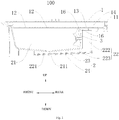
- a dissolution device 100 for a drum washing machine will be described with reference to Figs. 1-6 .
- the dissolution device 100 includes a water input box 1, a dissolution box 2, and an impeller 3.
- the water input box 1 is provided with a water inlet 11, a first drain port 12 in communication with the water inlet 11, and a flushing port 16 in communication with the dissolution box 2.
- the dissolution box 2 is disposed below the water input box 1 and defines a first dissolution chamber 21 in communication with the first drain port 12.
- a bottom wall of the first dissolution chamber 21 is formed as an inverted cone and provided with a first water outlet 211 to discharge water.
- the impeller 3 is rotatably disposed to a side wall of the dissolution box 2 and located at the flushing port 16, such that water in the water input box 1 rushes towards the impeller 3 through the flushing port 16 to drive the impeller 3 to rotate.
- the dissolution device 100 is adapted to be installed to the drum washing machine to receive washing powder, washing liquid or other detergents.
- the water input box 1 is provided with the water inlet 11, the first drain port 12, and the flushing port 16, in which the water inlet 11 is connected with a water source, and for example, the water inlet 11 may be connected with a faucet.
- the dissolution box 2 defines the first dissolution chamber 21 into which the washing powder, washing liquid or other detergents may be put.
- the first dissolution chamber 21 is in communication with the first drain port 12, and water flows from the water inlet 11 into the water input box 1, and flows towards the first dissolution chamber 21 through the first drain port 12, to dissolve the detergent in the first dissolution chamber 21.
- the bottom wall of the first dissolution chamber 21 is formed as the inverted cone, and the water flows along the bottom wall of the first dissolution chamber 21, such that a swirling water flow can be formed in the first dissolution chamber 21, thereby promoting the flowing of water, so as to achieve sufficient dissolution of the detergent in the first dissolution chamber 21 and improve dissolution efficiency of the detergent, thereby making the clothes sufficiently cleaned and improving a cleaning effect of the washing machine.
- the first water outlet 211 is disposed in the bottom wall of the first dissolution chamber 21, and the water in the first dissolution chamber 21 flows out from the first water outlet 211.
- the first water outlet 211 may be disposed at a bottom end of the bottom wall of the first dissolution chamber 21.
- the first water outlet 211 may be disposed at the lowest point of the bottom wall of the first dissolution chamber 21, such that the water in the first dissolution chamber 21 flows to the first water outlet 211 and forms a vortex at the first water outlet 211, which can not only facilitate the dissolution of the detergent in the first dissolution chamber 21, but also ensure that the detergent and water in the first dissolution chamber 21 are completely discharged to avoid residues in the first dissolution chamber 21.
- the impeller 3 is rotatably disposed in the first dissolution chamber 21 and disposed to a side wall of the first dissolution chamber 21, and the impeller 3 is arranged corresponding to the flushing port 16 in an up-and-down direction, such that the water in the water input box 1 flows downwards through the flushing port 16 and is directed towards the impeller 3 to drive the impeller 3 to rotate, so as to agitate the detergent in the first dissolution chamber 21, thereby promoting the dissolution of the detergent and dissolving the detergent completely. In such a way, the dissolution rate of the detergent is raised, and thus the cleaning effect of the washing machine is improved.
- the impeller 3 can be rotated by itself under the action of the water flow, and no external force is required to drive the impeller 3 to rotate.
- the impeller 2 may be disposed to a rear side wall of the first dissolution chamber 21; as illustrated in Figs. 4 and 6 , the impeller 3 may be disposed to a left side wall of the first dissolution chamber 21.
- the flushing port 16 is located above the impeller 3 to allow the water to rush towards the impeller 3 directly from the flushing port 16.
- the impeller 3 has an axis extendable along a horizontal direction and located below the flushing port 16, that is, the impeller 3 is horizontally arranged.
- the axis of the impeller 3 may be perpendicular to the side wall of the first dissolution chamber 21, to facilitate the installation and assembly of the impeller 3, and moreover, the water rushes from the flushing port 16 to the impeller 3, which is also conductive to driving the impeller 3 to rotate. Meanwhile, under the action of gravity, the water rushes vertically downwards from the flushing port 16 towards blades of the impeller 3, thereby further enhancing the impact of the water flow on the blades to ensure a rotation effect of the impeller 3.
- the bottom wall of the first dissolution chamber 21 is formed as the inverted cone, and the water flows along the bottom wall of the first dissolution chamber 21, whereby the swirling water flow can be formed in the first dissolution chamber 21, and hence the detergent in the first dissolution chamber 21 is sufficiently dissolved, thereby improving the dissolution efficiency of the detergent and making the clothes sufficiently cleaned, so as to improve the cleaning effect of the washing machine.
- the first dissolution chamber 21 is provided with the impeller 3 therein, the water input box 1 is provided with the flushing port 16, and the flushing port 16 is arranged corresponding to the impeller 3, such that the water in the water input box 1 can be directed towards the impeller 3 through the flushing port 16 to drive the impeller 3 to rotate, so as to agitate the detergent in the first dissolution chamber 21 to rotate.
- the dissolution efficiency of the detergent is improved to realize the sufficient dissolution of the detergent and hence upgrade the cleaning effect of the washing machine.
- the dissolution box 2 defines a second dissolution chamber 22 spaced apart from the first dissolution chamber 21 and communicated with the first water outlet 211.
- the water input box 1 is provided with a second drain port 13 in communication with the second dissolution chamber 22.
- a second water outlet 221 is provided in a wall of the second dissolution chamber 22 to discharge water into a drum of the washing machine.
- the dissolution box 2 defines the second dissolution chamber 22 therein, the second dissolution chamber 22 is spaced apart from the first dissolution chamber 21 and is in communication with the first water outlet 211, and the water input box 1 is provided with the second drain port 13, such that the water in the water input box 1 flows through the first drain port 12 to the first dissolution chamber 21, to impinge on the detergent of the first dissolution chamber 21 and meanwhile flows to the second dissolution chamber 22 through the second drain port 13. That is, the water in the water input box 1 may flow to the dissolution box 2 through the first drain port 12 and the second drain port 13 to improve water input efficiency.
- a relatively large water flow exists in the second dissolution chamber 22, and may pour into the first dissolution chamber 21 through the first water outlet 211 under pressure to impinge on the detergent in the first dissolution chamber 21 from the bottom of the first dissolution chamber 21, so as to further improve the dissolution efficiency of the detergent.
- a mixed liquid as a result of dissolution of the detergent may form a swirling water flow in the first dissolution chamber 21 to promote the dissolution of the detergent, and may flow from the first water outlet 211 to the second dissolution chamber 22. Since the second dissolution chamber 22 is provided with the second water outlet 221, the mixed liquid after the detergent is dissolved may flow into the drum of the washing machine.
- the second drain port 13 is located upstream of the first drain port 12, that is, the water may first pass through the second drain port 13 and then flow to the first drain port 12 when flowing in the water input box 1. Therefore, when the washing machine performs washing, water enters the water input box 1 from the water inlet 11, flows through the first drain port 12 to the first dissolution chamber 21 to impinge on the detergent in the first dissolution chamber 21, and flows through the second drain port 13 to the second dissolution chamber 22. The water in the second dissolution chamber 22 pours into the first dissolution chamber 21 through the first water outlet 211 to impinge on the detergent in the first dissolution chamber 21 from the bottom of the first dissolution chamber 21.
- the mixed liquid may form a swirling water flow in the first dissolution chamber 21, and flow from the first water outlet 211 to the second dissolution chamber 22, and finally to the drum of the washing machine to finish the dissolution process of the detergent, thereby further increasing the dissolution rate of the detergent and simplifying the structure.
- the first water outlet 211 may be disposed between the second drain port 13 and the second water outlet 221. As illustrated in Fig. 1 , in a water flowing direction, the first water outlet 211 is located between the second drain port 13 and the second water outlet 221, such that the water in the water input box 1 flows from the second drain port 13 to the second dissolution chamber 22.
- the water When flowing in the second dissolution chamber 22, the water may first pass through the first water outlet 211, pour into the first dissolution chamber 21 through the first water outlet to impinge on the detergent in the first dissolution chamber 21 from the bottom of the first dissolution chamber 21, and then flow to the second water outlet 221 to flow into the drum of the washing machine through the second water outlet 221, which can ensure that the water in the second dissolution chamber 22 can rush towards the first dissolution chamber 21 through the first water outlet 211 to impinge on the detergent.
- the second dissolution chamber 22 can include a first cavity 222 and a second cavity 223 in communication with each other.
- the first cavity 222 is disposed at a side of the first dissolution chamber 21, and the second cavity 223 is disposed below the first dissolution chamber 21.
- a part of the second cavity 223 located between the first cavity 222 and the first water outlet 211 has a gradually decreased flow area in a direction from the first cavity 222 to the first water outlet 211.
- the first cavity 222 is defined at a rear side of the first dissolution chamber 21 and extends along a vertical direction.
- the second cavity 223 is in communication with the first cavity 222 and located below the first dissolution chamber 21.
- the first water outlet 211 is in communication with the second cavity 223 and located above the second cavity 223.
- a part of the second cavity 223 located between the first cavity 222 and the first water outlet 211 has a gradually decreased flow area to ensure that the water can smoothly pour into the first dissolution chamber 21 through the first water outlet 211 when passing through the first water outlet 211.
- the dissolution box 2 can include an upper dissolution box 23 and a lower dissolution box 24.
- the upper dissolution box 23 defines the first dissolution chamber 21 therein, and the second dissolution chamber 22 is defined between the lower dissolution box 24 and the upper dissolution box 23.
- the upper dissolution box defines the first dissolution chamber 21 therein and is located below the water input box 1;
- the lower dissolution box 24 is disposed outside the upper dissolution box 23 and defines, together with the first dissolution box 2, the second dissolution chamber 22, such that the dissolution box 2 has a simple structure.
- the upper dissolution box 23 has an upper end spaced apart from the water input box 1 to form a water circulation gap 15, through which the first dissolution chamber 21 and the second dissolution chamber 22 are communicated.
- a water circulation gap 15 As illustrated in Fig. 1 , an upper end face of a side wall of the upper dissolution box 23 adjacent to the second dissolution chamber 22 can be at least partially spaced apart from a lower end face of the water input box 1, and the water circulation gap 15 is thus formed, so as to communicate the first dissolution chamber 21 with the second dissolution chamber 22.
- the water in the first dissolution chamber 21 can flow to the second dissolution chamber 22 through the water circulation gap 15, which can facilitate the flow of water in the dissolution box 2 and alleviate the pressure in the first dissolution chamber 21 to prevent the water from flowing back to the first dissolution chamber 21.
- a plurality of first drain ports 12 may be provided, and the plurality of first drain ports 12 are disposed in a bottom wall of the water input box 1 and located above the first dissolution chamber 21.
- the water in the water input box 1 can flow into the first dissolution chamber 21 through the plurality of first drain ports 12, so as to facilitate water input from the water input box 1 to the first dissolution chamber 21.
- the plurality of first drain ports 12 may be arranged in a distributed manner, such that the water flows from the plurality of first drain ports 12 to the first dissolution chamber 21 in a distributed manner, thereby facilitating the formation of the swirling water flow in the first dissolution chamber 21.
- the water input box 1 is provided with a water retaining rib to guide the water from the water inlet 11 to the first drain port 12 and the second drain port 13.
- a water dividing rib 14 to facilitate the flow of water in the water input box 1.
- the dissolution box 2 can further define a third dissolution chamber 25 and a fourth dissolution chamber 26, and the third dissolution chamber 25 and the fourth dissolution chamber 26 are both communicated with the drum of the washing machine and spaced apart from the first dissolution chamber 21.
- the first dissolution chamber 21 may be formed as a main detergent chamber, that is, the washing liquid or washing powder is put in the first dissolution chamber 21; the third dissolution chamber 25 and the fourth dissolution chamber 26 can be separately used to receive a garment care agent, such as a softener, a fluffing agent or the like.
- the water in the water input box 1 can be divided and guided by the water dividing rib 14 to flow to the first dissolution chamber 21 and the second dissolution chamber 22.
- the water inlet 11 may include a first inlet 111 and a second inlet 112.
- the water input box 1 is divided into a plurality of water input chambers, namely a first water input chamber 17 in communication with the first dissolution chamber 21, a second water input chamber 18 in communication with the third dissolution chamber 25, and a third water input chamber 19 in communication with the fourth dissolution chamber 26, as illustrated in Figs. 2 and 5 .
- the first inlet 111 and the second inlet 112 can be used to generate water input in a crossed form, and the first inlet 111 and the second inlet 112 can be used for water input simultaneously or separately. Under the action of the water dividing rib, the water from the water inlet 11 can flow to the first water input chamber 17, the second water input chamber 18, and the third water input chamber 19 separately.
- the water when the water enters from the first inlet 111, the water is guided to the first water input chamber 17 and flows to the first dissolution chamber 21; when the water enters only from the second inlet 112, the water flows to the third water input chamber 19 and flows to the fourth dissolution chamber 26; when the water enters the water input box 1 from the first inlet 111 and the second inlet 112 simultaneously, the water input from the first inlet 111 and the water input from the second inlet 112 impact against each other to allow the water to flow towards the second water input chamber 18 and towards the third dissolution chamber 25.
- the dissolution device 100 may include a water input box 1, a dissolution box 2, and an impeller 3.
- the dissolution box 2 can define a first dissolution chamber 21, a second dissolution chamber 22, a third dissolution chamber 25, and a fourth dissolution chamber 26 therein, and the first dissolution chamber 21, the third dissolution chamber 25, and the fourth dissolution chamber 26 are spaced apart from one another and juxtaposed.
- the third dissolution chamber 25 and the fourth dissolution chamber 26 are in communication with the drum of the washing machine, and the third dissolution chamber 25 and the fourth dissolution chamber 26 are used to receive a garment care agent, such as a softener, a fluffing agent or the like.
- the water input box 1 is provided with a water dividing rib 14 therein, and water entering from a water inlet 11 can be divided and guided by means of the water dividing rib 14 to guide the water entering from the water inlet 11 into the first dissolution chamber 21, the second dissolution chamber 22, the third dissolution chamber 25, and the fourth dissolution chamber 26.
- the first dissolution chamber 21 can be used to receive the detergent, such as the washing powder or the washing liquid.
- the water input box 1 is provided with the water inlet 11, a first drain port 12, a second drain port 13, and a flushing port 16.
- the dissolution box 2 is disposed below the water input box 1, and includes an upper dissolution box 23 and a lower dissolution box 24.
- the upper dissolution box 23 defines the first dissolution chamber 21 therein, and the lower dissolution box 24 is disposed outside the upper dissolution box 23 and defines the second dissolution chamber 22 together with the upper dissolution box 23.
- the first drain port 12 is in communication with the first dissolution chamber 21, and the second drain port 13 is in communication with the second dissolution chamber 22.
- the first dissolution chamber 21 has a bottom wall formed as an inverted cone, and a first water outlet 211 is provided at the lowest point of the first dissolution chamber 21, by which the water in the first dissolution chamber 21 flows outwards, such that the water in the first dissolution chamber 21 may form the swirling water flow to facilitate mixture with the detergent and dissolution of the detergent.
- the impeller 3 is rotatably disposed to a side wall of the first dissolution chamber 21, and the impeller 3 has an axis extendable along a horizontal direction and located below the flushing port 16, such that the water in the water inlet 11 is directed from the flushing port 16 towards the impeller 3 to drive the impeller 3 to rotate, so as to agitate the detergent in the first dissolution chamber 21, thereby promoting the dissolution of the detergent and dissolving the detergent completely. In such a way, the dissolution rate of the detergent is raised, and thus the cleaning effect of the washing machine is improved. Moreover, the impeller 3 can be rotated by itself, and no external force is required to drive the impeller 3 to rotate.
- the first water outlet 211 is in communication with the second dissolution chamber 22, and when the water in the second dissolution chamber 22 flows through the first water outlet 211, under the action of water pressure, the water may pour into the first dissolution chamber 21 through the first water outlet to impinge on the detergent from the bottom of the first dissolution chamber 21, and then flow towards the second water outlet 221 to flow into the drum of the washing machine through the second water outlet 221, which can further improve the dissolution efficiency of the detergent.
- the water in the second dissolution chamber 22 flows through the first water outlet 211, the water pours into the first dissolution chamber 21 through the first water outlet 211 to impinge on the detergent in the first dissolution chamber 21 from the bottom of the first dissolution chamber 21, which can realize the sufficient dissolution of the detergent and improve the dissolution efficiency thereof.
- the mixed liquid after the detergent is dissolved may form the swirling water flow in the first dissolution chamber 21, flow to the second dissolution chamber 22 from the first water outlet 211, and finally flow to the drum of the washing machine from the second water outlet 221 so as to finish the dissolution process of the detergent, which can further improve the dissolution rate of the detergent and simplify the structure of the dissolution box 2.
- the bottom wall of the first dissolution chamber 21 is formed as the inverted cone, whereby the swirling water flow can be formed in the first dissolution chamber 21.
- the impeller 3 is disposed in the first dissolution chamber 21 and the water in the water input box 1 is directed towards the impeller 3 through the flushing port 16 to drive the impeller 3 to rotate, so as to agitate the detergent in the first dissolution chamber 21, thereby promoting the dissolution of the detergent and enabling the detergent to be completely dissolved.
- the water in the second dissolution chamber 22 flows to the first dissolution chamber 21 through the first water outlet 211 to impinge on the detergent in the first dissolution chamber 21 from the bottom of the first dissolution chamber 21, thereby further improving the dissolution efficiency of the detergent and making the clothes sufficiently cleaned, so as to improve the cleaning effect of the washing machine and simplifying the structure.
- the present disclosure provides a washing machine including the above dissolution device 100 according to the above embodiments.
- the drum washing machine according to embodiments of the present disclosure also has the above technical effects, that is, the washing machine according to embodiments of the present disclosure can facilitate the sufficient dissolution of the detergent and raise the dissolution efficiency by means of the dissolution device 100 according to the above embodiments, thereby improving the cleaning effect of the drum washing machine.
- a structure in which a first feature is "on" or “below” a second feature may include an embodiment in which the first feature is in direct contact with the second feature, and may also include an embodiment in which the first feature and the second feature are not in direct contact with each other, but are contacted via an additional feature formed therebetween.
- a first feature "on,” “above,” or “on top of' a second feature may include an embodiment in which the first feature is right or obliquely “on,” “above,” or “on top of' the second feature, or just means that the first feature is at a height higher than that of the second feature; while a first feature "below,” “under,” or “on bottom of' a second feature may include an embodiment in which the first feature is right or obliquely “below,” “under,” or “on bottom of' the second feature, or just means that the first feature is at a height lower than that of the second feature.
Landscapes
- Engineering & Computer Science (AREA)
- Textile Engineering (AREA)
- Detail Structures Of Washing Machines And Dryers (AREA)
Abstract
Description
- The present disclosure relates to a technical field of washing machines, and more particularly to a dissolution device and a drum washing machine having the same.
- With the continuous improvement of people's living standards, consumers are paying more attention to the health attributes of household appliances while pursuing convenient life, in order to provide safer and more comfortable experience for their families. As far as washing machine products are concerned, numerous synthetic chemical detergents are commercially available. If these detergents are not completely dissolved, they often remain on the clothes and damage the clothes, and worse still, they may be very irritating to human skin and be harmful to human health after long-term contact with human skin. Meanwhile, these insufficiently dissolved detergents not only fail to clean the clothes completely, but also have a serious impact on the natural environment.
- An existing drum washing machine mainly employs such a detergent delivery method that washing powder or washing liquid is put in a detergent box and brought into the washing machine by an influent water flow. In this process, the detergent is not completely dissolved, and especially the washing powder is prone to agglomeration, forming residue in the detergent box, in which active ingredients of the detergent are not fully utilized to wash clothes, thereby degrading a cleaning effect on the clothes.
- The present disclosure seeks to solve at least one of the problems existing in the related art to at least some extent. Therefore, the present disclosure provides a dissolution device for a drum washing machine, which can improve dissolution efficiency of a detergent to dissolve the detergent completely.
- The present disclosure further provides a drum washing machine that has the above dissolution device.
- The dissolution device according to embodiments of a first aspect of the present disclosure includes: a water input box provided with a water inlet, a first drain port in communication with the water inlet, and a flushing port in communication with a dissolution box; the dissolution box located below the water input box, and defining a first dissolution chamber in communication with the first drain port, the first dissolution chamber having a bottom wall that is formed as an inverted cone and is provided with a first water outlet to discharge water; and an impeller rotatably disposed to a side wall of the dissolution box and located at the flushing port, through which water in the water input box rushes towards the impeller to drive the impeller to rotate.
- For the dissolution device according to embodiments of the present disclosure, the bottom wall of the first dissolution chamber is formed as the inverted cone, and the water flows along the bottom wall of the first dissolution chamber, whereby a swirling water flow can be formed in the first dissolution chamber to enable the detergent in the first dissolution chamber to be sufficiently dissolved, thereby improving the dissolution efficiency of the detergent and making the clothes sufficiently cleaned, so as to improve a cleaning effect of the washing machine.
- Moreover, the impeller is disposed in the first dissolution chamber, and the water input box is provided with the flushing port arranged corresponding to the impeller, such that the water in the water input box can be directed towards the impeller through the flushing port to drive the impeller to rotate, so as to agitate the detergent in the first dissolution chamber, thereby further improving the dissolution efficiency of the detergent and achieve the sufficient dissolution of the detergent, so as to further upgrade the cleaning effect of the washing machine.
- In addition, the dissolution device according to embodiments of the present disclosure may have the following additional technical features.
- According to some embodiments of the present disclosure, the first water outlet is disposed at a bottom end of the bottom wall of the first dissolution chamber.
- According to some embodiments of the present disclosure, the dissolution box defines a second dissolution chamber spaced apart from the first dissolution chamber and communicated with the first water outlet, the water input box is provided with the first water outlet in communication with the second dissolution chamber, and a second water outlet is provided in a wall of the second dissolution chamber to discharge water into a drum of the washing machine.
- Optionally, the first water outlet is disposed between the second drain port and the second water outlet.
- Further, the second dissolution chamber includes a first cavity and a second cavity in communication with each other, the first cavity is disposed at a side of the first dissolution chamber, the second cavity is disposed at a bottom of the first dissolution chamber, and a part of the second cavity located between the first cavity and the second drain port has a gradually decreased flow area in a direction from the first cavity to the second drain port.
- Optionally, the dissolution box includes: an upper dissolution box defining the first dissolution chamber therein; and a lower dissolution box, the second dissolution chamber being defined between the lower dissolution box and the upper dissolution box.
- Further, the upper dissolution box has an upper end spaced apart from the water input box to form a water circulation gap, through which the first dissolution chamber is communicated with the second dissolution chamber.
- According to some embodiments of the present disclosure, a plurality of the first drain ports are provided, and the plurality of the first drain ports are disposed in a bottom wall of the water input box and located above the first dissolution chamber.
- According to some embodiments of the present disclosure, the water input box is provided with a water retaining rib therein to guide the water from the water inlet to the first drain port and the second drain port.
- The drum washing machine according to embodiments of a second aspect of the present disclosure has the dissolution device according to the above embodiments.
- Since the washing machine with the dissolution device according to the above embodiments has the above technical effects, the drum washing machine according to embodiments of the present disclosure also has the above technical effects, that is, the washing machine according to embodiments of the present disclosure can facilitate the sufficient dissolution of the detergent and raise the dissolution efficiency by means of the dissolution device according to the above embodiments, thereby improving the cleaning effect of the drum washing machine.
- Additional aspects and advantages of embodiments of the present disclosure will be given in part in the following description, become apparent in part from the following description, or be learned from the practice of the embodiments of the present disclosure.
-
-
Fig. 1 illustrates a schematic view of a dissolution device for a drum washing machine according to an embodiment of the present disclosure. -
Fig. 2 illustrates a schematic view of a water input box of a dissolution device for a drum washing machine according to an embodiment of the present disclosure. -
Fig. 3 illustrates a schematic view of a dissolution box of a dissolution device for a drum washing machine according to an embodiment of the present disclosure. -
Fig. 4 illustrates a schematic view of a dissolution device for a drum washing machine according to another embodiment of the present disclosure. -
Fig. 5 illustrates a schematic view of a water input box of a dissolution device for a drum washing machine according to another embodiment of the present disclosure. -
Fig. 6 illustrates a schematic view of a dissolution box of a dissolution device for a drum washing machine according to another embodiment of the present disclosure. -
- 100 dissolution device for drum washing machine,
- 1 water input box, 11 water inlet, 111 first inlet, 112 second inlet, 12 first drain port, 13 second drain port, 14 water dividing rib, 15 water circulation gap, 16 flushing port, 17 first water input chamber, 18 second water input chamber, 19 third water input chamber;
- 2 dissolution box, 21 first dissolution chamber, 211 first water outlet, 22 second dissolution chamber, 221 second water outlet, 222 first cavity, 223 second cavity, 23 upper dissolution box, 24 lower dissolution box, 25 third dissolution chamber, 26 fourth dissolution chamber;
- 3 impeller.
- Embodiments of the present disclosure will be described in detail and examples of the embodiments will be illustrated in the drawings. The embodiments described herein with reference to drawings are explanatory, which are merely used to illustrate the present disclosure, but shall not be construed to limit the present disclosure.
- In the specification, it is to be understood that terms such as "central," "longitudinal," "lateral," "length," "width," "thickness," "upper," "lower," "front," "rear," "left," "right," "vertical," "horizontal," "top," "bottom," "inner," "outer," "clockwise," "counterclockwise," "axial," "radial," and "circumferential" should be construed to refer to the orientation or position relationship as described or as shown in the drawings under discussion. These relative terms are for convenience and simplification of description, and do not indicate or imply that the present disclosure must have a particular orientation or be constructed and operated in a particular orientation. Thus, these relative terms should not be constructed to limit the present disclosure.
- In addition, terms such as "first" and "second" are used herein for purposes of description and are not intended to indicate or imply relative importance or significance or to imply the number of indicated technical features. Thus, the feature defined with "first" and "second" may include one or more of this feature. In the description of the present disclosure, the term "a plurality of' means at least two, for example, two, three or etc., unless specified otherwise.
- In the present disclosure, unless specified or limited otherwise, the terms "mounted," "connected," "coupled," "fixed" and the like are used broadly, and may be, for example, fixed connections, detachable connections, or integral connections; may also be mechanical connection, electrical connections, or mutual communication; may also be direct connections or indirect connections via intervening structures; may also be inner communications or mutual interaction of two elements, which can be understood by those skilled in the art according to specific situations.
- A
dissolution device 100 for a drum washing machine according to embodiments of the present disclosure will be described with reference toFigs. 1-6 . - As illustrated in
Figs. 1-6 , thedissolution device 100 according to embodiments of the present disclosure includes awater input box 1, adissolution box 2, and animpeller 3. - Specifically, the
water input box 1 is provided with awater inlet 11, afirst drain port 12 in communication with thewater inlet 11, and aflushing port 16 in communication with thedissolution box 2. Thedissolution box 2 is disposed below thewater input box 1 and defines afirst dissolution chamber 21 in communication with thefirst drain port 12. A bottom wall of thefirst dissolution chamber 21 is formed as an inverted cone and provided with afirst water outlet 211 to discharge water. Theimpeller 3 is rotatably disposed to a side wall of thedissolution box 2 and located at the flushingport 16, such that water in thewater input box 1 rushes towards theimpeller 3 through theflushing port 16 to drive theimpeller 3 to rotate. - In other words, the
dissolution device 100 according to embodiments of the present disclosure is adapted to be installed to the drum washing machine to receive washing powder, washing liquid or other detergents. - The
water input box 1 is provided with thewater inlet 11, thefirst drain port 12, and theflushing port 16, in which thewater inlet 11 is connected with a water source, and for example, thewater inlet 11 may be connected with a faucet. Thedissolution box 2 defines thefirst dissolution chamber 21 into which the washing powder, washing liquid or other detergents may be put. Thefirst dissolution chamber 21 is in communication with thefirst drain port 12, and water flows from thewater inlet 11 into thewater input box 1, and flows towards thefirst dissolution chamber 21 through thefirst drain port 12, to dissolve the detergent in thefirst dissolution chamber 21. - The bottom wall of the
first dissolution chamber 21 is formed as the inverted cone, and the water flows along the bottom wall of thefirst dissolution chamber 21, such that a swirling water flow can be formed in thefirst dissolution chamber 21, thereby promoting the flowing of water, so as to achieve sufficient dissolution of the detergent in thefirst dissolution chamber 21 and improve dissolution efficiency of the detergent, thereby making the clothes sufficiently cleaned and improving a cleaning effect of the washing machine. Thefirst water outlet 211 is disposed in the bottom wall of thefirst dissolution chamber 21, and the water in thefirst dissolution chamber 21 flows out from thefirst water outlet 211. Preferably, thefirst water outlet 211 may be disposed at a bottom end of the bottom wall of thefirst dissolution chamber 21. That is, thefirst water outlet 211 may be disposed at the lowest point of the bottom wall of thefirst dissolution chamber 21, such that the water in thefirst dissolution chamber 21 flows to thefirst water outlet 211 and forms a vortex at thefirst water outlet 211, which can not only facilitate the dissolution of the detergent in thefirst dissolution chamber 21, but also ensure that the detergent and water in thefirst dissolution chamber 21 are completely discharged to avoid residues in thefirst dissolution chamber 21. - As illustrated in
Figs. 1 ,3 ,4 and6 , theimpeller 3 is rotatably disposed in thefirst dissolution chamber 21 and disposed to a side wall of thefirst dissolution chamber 21, and theimpeller 3 is arranged corresponding to theflushing port 16 in an up-and-down direction, such that the water in thewater input box 1 flows downwards through theflushing port 16 and is directed towards theimpeller 3 to drive theimpeller 3 to rotate, so as to agitate the detergent in thefirst dissolution chamber 21, thereby promoting the dissolution of the detergent and dissolving the detergent completely. In such a way, the dissolution rate of the detergent is raised, and thus the cleaning effect of the washing machine is improved. Moreover, theimpeller 3 can be rotated by itself under the action of the water flow, and no external force is required to drive theimpeller 3 to rotate. For example, as illustrated inFigs. 1 and3 , theimpeller 2 may be disposed to a rear side wall of thefirst dissolution chamber 21; as illustrated inFigs. 4 and6 , theimpeller 3 may be disposed to a left side wall of thefirst dissolution chamber 21. The flushingport 16 is located above theimpeller 3 to allow the water to rush towards theimpeller 3 directly from the flushingport 16. - Optionally, the
impeller 3 has an axis extendable along a horizontal direction and located below the flushingport 16, that is, theimpeller 3 is horizontally arranged. The axis of theimpeller 3 may be perpendicular to the side wall of thefirst dissolution chamber 21, to facilitate the installation and assembly of theimpeller 3, and moreover, the water rushes from the flushingport 16 to theimpeller 3, which is also conductive to driving theimpeller 3 to rotate. Meanwhile, under the action of gravity, the water rushes vertically downwards from the flushingport 16 towards blades of theimpeller 3, thereby further enhancing the impact of the water flow on the blades to ensure a rotation effect of theimpeller 3. - Therefore, for the
dissolution device 100 according to embodiments of the present disclosure, the bottom wall of thefirst dissolution chamber 21 is formed as the inverted cone, and the water flows along the bottom wall of thefirst dissolution chamber 21, whereby the swirling water flow can be formed in thefirst dissolution chamber 21, and hence the detergent in thefirst dissolution chamber 21 is sufficiently dissolved, thereby improving the dissolution efficiency of the detergent and making the clothes sufficiently cleaned, so as to improve the cleaning effect of the washing machine. - Further, the
first dissolution chamber 21 is provided with theimpeller 3 therein, thewater input box 1 is provided with the flushingport 16, and the flushingport 16 is arranged corresponding to theimpeller 3, such that the water in thewater input box 1 can be directed towards theimpeller 3 through the flushingport 16 to drive theimpeller 3 to rotate, so as to agitate the detergent in thefirst dissolution chamber 21 to rotate. In such a way, the dissolution efficiency of the detergent is improved to realize the sufficient dissolution of the detergent and hence upgrade the cleaning effect of the washing machine. - In some embodiments of the present disclosure, the
dissolution box 2 defines asecond dissolution chamber 22 spaced apart from thefirst dissolution chamber 21 and communicated with thefirst water outlet 211. Thewater input box 1 is provided with asecond drain port 13 in communication with thesecond dissolution chamber 22. Asecond water outlet 221 is provided in a wall of thesecond dissolution chamber 22 to discharge water into a drum of the washing machine. - In other words, the
dissolution box 2 defines thesecond dissolution chamber 22 therein, thesecond dissolution chamber 22 is spaced apart from thefirst dissolution chamber 21 and is in communication with thefirst water outlet 211, and thewater input box 1 is provided with thesecond drain port 13, such that the water in thewater input box 1 flows through thefirst drain port 12 to thefirst dissolution chamber 21, to impinge on the detergent of thefirst dissolution chamber 21 and meanwhile flows to thesecond dissolution chamber 22 through thesecond drain port 13. That is, the water in thewater input box 1 may flow to thedissolution box 2 through thefirst drain port 12 and thesecond drain port 13 to improve water input efficiency. Moreover, a relatively large water flow exists in thesecond dissolution chamber 22, and may pour into thefirst dissolution chamber 21 through thefirst water outlet 211 under pressure to impinge on the detergent in thefirst dissolution chamber 21 from the bottom of thefirst dissolution chamber 21, so as to further improve the dissolution efficiency of the detergent. A mixed liquid as a result of dissolution of the detergent may form a swirling water flow in thefirst dissolution chamber 21 to promote the dissolution of the detergent, and may flow from thefirst water outlet 211 to thesecond dissolution chamber 22. Since thesecond dissolution chamber 22 is provided with thesecond water outlet 221, the mixed liquid after the detergent is dissolved may flow into the drum of the washing machine. - In an example illustrated in
Figs. 1 and2 , thesecond drain port 13 is located upstream of thefirst drain port 12, that is, the water may first pass through thesecond drain port 13 and then flow to thefirst drain port 12 when flowing in thewater input box 1. Therefore, when the washing machine performs washing, water enters thewater input box 1 from thewater inlet 11, flows through thefirst drain port 12 to thefirst dissolution chamber 21 to impinge on the detergent in thefirst dissolution chamber 21, and flows through thesecond drain port 13 to thesecond dissolution chamber 22. The water in thesecond dissolution chamber 22 pours into thefirst dissolution chamber 21 through thefirst water outlet 211 to impinge on the detergent in thefirst dissolution chamber 21 from the bottom of thefirst dissolution chamber 21. After the detergent is dissolved, the mixed liquid may form a swirling water flow in thefirst dissolution chamber 21, and flow from thefirst water outlet 211 to thesecond dissolution chamber 22, and finally to the drum of the washing machine to finish the dissolution process of the detergent, thereby further increasing the dissolution rate of the detergent and simplifying the structure. - Optionally, the
first water outlet 211 may be disposed between thesecond drain port 13 and thesecond water outlet 221. As illustrated inFig. 1 , in a water flowing direction, thefirst water outlet 211 is located between thesecond drain port 13 and thesecond water outlet 221, such that the water in thewater input box 1 flows from thesecond drain port 13 to thesecond dissolution chamber 22. When flowing in thesecond dissolution chamber 22, the water may first pass through thefirst water outlet 211, pour into thefirst dissolution chamber 21 through the first water outlet to impinge on the detergent in thefirst dissolution chamber 21 from the bottom of thefirst dissolution chamber 21, and then flow to thesecond water outlet 221 to flow into the drum of the washing machine through thesecond water outlet 221, which can ensure that the water in thesecond dissolution chamber 22 can rush towards thefirst dissolution chamber 21 through thefirst water outlet 211 to impinge on the detergent. - In some examples of the present disclosure, the
second dissolution chamber 22 can include afirst cavity 222 and asecond cavity 223 in communication with each other. Thefirst cavity 222 is disposed at a side of thefirst dissolution chamber 21, and thesecond cavity 223 is disposed below thefirst dissolution chamber 21. A part of thesecond cavity 223 located between thefirst cavity 222 and thefirst water outlet 211 has a gradually decreased flow area in a direction from thefirst cavity 222 to thefirst water outlet 211. Thus, it is advantageous to the following process that the water in thesecond dissolution chamber 22 pours into thefirst dissolution chamber 21 through thefirst water outlet 211 to impinge on the detergent in thefirst dissolution chamber 21 from the bottom of thefirst dissolution chamber 21. - As illustrated in
Fig. 1 , thefirst cavity 222 is defined at a rear side of thefirst dissolution chamber 21 and extends along a vertical direction. Thesecond cavity 223 is in communication with thefirst cavity 222 and located below thefirst dissolution chamber 21. Thefirst water outlet 211 is in communication with thesecond cavity 223 and located above thesecond cavity 223. In a rear-to-front direction, a part of thesecond cavity 223 located between thefirst cavity 222 and thefirst water outlet 211 has a gradually decreased flow area to ensure that the water can smoothly pour into thefirst dissolution chamber 21 through thefirst water outlet 211 when passing through thefirst water outlet 211. - In some examples of the present disclosure, the
dissolution box 2 can include anupper dissolution box 23 and alower dissolution box 24. Theupper dissolution box 23 defines thefirst dissolution chamber 21 therein, and thesecond dissolution chamber 22 is defined between thelower dissolution box 24 and theupper dissolution box 23. Specifically, the upper dissolution box defines thefirst dissolution chamber 21 therein and is located below thewater input box 1; thelower dissolution box 24 is disposed outside theupper dissolution box 23 and defines, together with thefirst dissolution box 2, thesecond dissolution chamber 22, such that thedissolution box 2 has a simple structure. - Further, the
upper dissolution box 23 has an upper end spaced apart from thewater input box 1 to form a water circulation gap 15, through which thefirst dissolution chamber 21 and thesecond dissolution chamber 22 are communicated. As illustrated inFig. 1 , an upper end face of a side wall of theupper dissolution box 23 adjacent to thesecond dissolution chamber 22 can be at least partially spaced apart from a lower end face of thewater input box 1, and the water circulation gap 15 is thus formed, so as to communicate thefirst dissolution chamber 21 with thesecond dissolution chamber 22. In such a case, when thefirst dissolution chamber 21 is full of water, the water in thefirst dissolution chamber 21 can flow to thesecond dissolution chamber 22 through the water circulation gap 15, which can facilitate the flow of water in thedissolution box 2 and alleviate the pressure in thefirst dissolution chamber 21 to prevent the water from flowing back to thefirst dissolution chamber 21. - In some embodiments of the present disclosure, a plurality of
first drain ports 12 may be provided, and the plurality offirst drain ports 12 are disposed in a bottom wall of thewater input box 1 and located above thefirst dissolution chamber 21. Thus, the water in thewater input box 1 can flow into thefirst dissolution chamber 21 through the plurality offirst drain ports 12, so as to facilitate water input from thewater input box 1 to thefirst dissolution chamber 21. In an example shown inFigs. 2 and5 , the plurality offirst drain ports 12 may be arranged in a distributed manner, such that the water flows from the plurality offirst drain ports 12 to thefirst dissolution chamber 21 in a distributed manner, thereby facilitating the formation of the swirling water flow in thefirst dissolution chamber 21. - Advantageously, the
water input box 1 is provided with a water retaining rib to guide the water from thewater inlet 11 to thefirst drain port 12 and thesecond drain port 13. Thus, the water flowing from thewater inlet 11 can be divided and guided by means of awater dividing rib 14 to facilitate the flow of water in thewater input box 1. - For example, as illustrated in
Figs. 3 and6 , thedissolution box 2 can further define athird dissolution chamber 25 and afourth dissolution chamber 26, and thethird dissolution chamber 25 and thefourth dissolution chamber 26 are both communicated with the drum of the washing machine and spaced apart from thefirst dissolution chamber 21. Thefirst dissolution chamber 21 may be formed as a main detergent chamber, that is, the washing liquid or washing powder is put in thefirst dissolution chamber 21; thethird dissolution chamber 25 and thefourth dissolution chamber 26 can be separately used to receive a garment care agent, such as a softener, a fluffing agent or the like. The water in thewater input box 1 can be divided and guided by thewater dividing rib 14 to flow to thefirst dissolution chamber 21 and thesecond dissolution chamber 22. - As illustrated in
Figs. 2 and5 , thewater inlet 11 may include afirst inlet 111 and asecond inlet 112. Thewater input box 1 is divided into a plurality of water input chambers, namely a firstwater input chamber 17 in communication with thefirst dissolution chamber 21, a secondwater input chamber 18 in communication with thethird dissolution chamber 25, and a thirdwater input chamber 19 in communication with thefourth dissolution chamber 26, as illustrated inFigs. 2 and5 . Thefirst inlet 111 and thesecond inlet 112 can be used to generate water input in a crossed form, and thefirst inlet 111 and thesecond inlet 112 can be used for water input simultaneously or separately. Under the action of the water dividing rib, the water from thewater inlet 11 can flow to the firstwater input chamber 17, the secondwater input chamber 18, and the thirdwater input chamber 19 separately. - Specifically, when the water enters from the
first inlet 111, the water is guided to the firstwater input chamber 17 and flows to thefirst dissolution chamber 21; when the water enters only from thesecond inlet 112, the water flows to the thirdwater input chamber 19 and flows to thefourth dissolution chamber 26; when the water enters thewater input box 1 from thefirst inlet 111 and thesecond inlet 112 simultaneously, the water input from thefirst inlet 111 and the water input from thesecond inlet 112 impact against each other to allow the water to flow towards the secondwater input chamber 18 and towards thethird dissolution chamber 25. - A specific example of the
dissolution device 100 according to embodiments of the present disclosure will be described with reference to the drawings. It could be understood that the following description is only illustrative and should not be constructed to limit the embodiments of the present disclosure. - As illustrated in
Figs. 1-6 , thedissolution device 100 according to the embodiment of the present disclosure may include awater input box 1, adissolution box 2, and animpeller 3. - As illustrated in
Figs. 1 ,3 ,4 and6 , thedissolution box 2 can define afirst dissolution chamber 21, asecond dissolution chamber 22, athird dissolution chamber 25, and afourth dissolution chamber 26 therein, and thefirst dissolution chamber 21, thethird dissolution chamber 25, and thefourth dissolution chamber 26 are spaced apart from one another and juxtaposed. Thethird dissolution chamber 25 and thefourth dissolution chamber 26 are in communication with the drum of the washing machine, and thethird dissolution chamber 25 and thefourth dissolution chamber 26 are used to receive a garment care agent, such as a softener, a fluffing agent or the like. Thewater input box 1 is provided with awater dividing rib 14 therein, and water entering from awater inlet 11 can be divided and guided by means of thewater dividing rib 14 to guide the water entering from thewater inlet 11 into thefirst dissolution chamber 21, thesecond dissolution chamber 22, thethird dissolution chamber 25, and thefourth dissolution chamber 26. Thefirst dissolution chamber 21 can be used to receive the detergent, such as the washing powder or the washing liquid. - The
water input box 1 is provided with thewater inlet 11, afirst drain port 12, asecond drain port 13, and a flushingport 16. Thedissolution box 2 is disposed below thewater input box 1, and includes anupper dissolution box 23 and alower dissolution box 24. Theupper dissolution box 23 defines thefirst dissolution chamber 21 therein, and thelower dissolution box 24 is disposed outside theupper dissolution box 23 and defines thesecond dissolution chamber 22 together with theupper dissolution box 23. Thefirst drain port 12 is in communication with thefirst dissolution chamber 21, and thesecond drain port 13 is in communication with thesecond dissolution chamber 22. - The
first dissolution chamber 21 has a bottom wall formed as an inverted cone, and afirst water outlet 211 is provided at the lowest point of thefirst dissolution chamber 21, by which the water in thefirst dissolution chamber 21 flows outwards, such that the water in thefirst dissolution chamber 21 may form the swirling water flow to facilitate mixture with the detergent and dissolution of the detergent. - The
impeller 3 is rotatably disposed to a side wall of thefirst dissolution chamber 21, and theimpeller 3 has an axis extendable along a horizontal direction and located below the flushingport 16, such that the water in thewater inlet 11 is directed from the flushingport 16 towards theimpeller 3 to drive theimpeller 3 to rotate, so as to agitate the detergent in thefirst dissolution chamber 21, thereby promoting the dissolution of the detergent and dissolving the detergent completely. In such a way, the dissolution rate of the detergent is raised, and thus the cleaning effect of the washing machine is improved. Moreover, theimpeller 3 can be rotated by itself, and no external force is required to drive theimpeller 3 to rotate. - The
first water outlet 211 is in communication with thesecond dissolution chamber 22, and when the water in thesecond dissolution chamber 22 flows through thefirst water outlet 211, under the action of water pressure, the water may pour into thefirst dissolution chamber 21 through the first water outlet to impinge on the detergent from the bottom of thefirst dissolution chamber 21, and then flow towards thesecond water outlet 221 to flow into the drum of the washing machine through thesecond water outlet 221, which can further improve the dissolution efficiency of the detergent. - When the washing machine performs washing, water enters the
water input box 1 from thewater inlet 11; under the diversion and guidance of thewater dividing rib 14, the water in thewater input box 1 flows to thefirst dissolution chamber 21 through thefirst drain port 12 to impinge on the detergent in thefirst dissolution chamber 21, and flows to thesecond dissolution chamber 22 through thesecond drain port 13; under the water pressure, the water in thesecond dissolution chamber 22 is directed from the flushingport 16 to theimpeller 3 to drive theimpeller 3 to rotate, so as to agitate the detergent in thefirst dissolution chamber 21, thereby promoting the dissolution of the detergent and enabling the detergent to be completely dissolved. In such a way, the dissolution rate of the detergent is raised, and no external force is required to drive theimpeller 3 to rotate. - When the water in the
second dissolution chamber 22 flows through thefirst water outlet 211, the water pours into thefirst dissolution chamber 21 through thefirst water outlet 211 to impinge on the detergent in thefirst dissolution chamber 21 from the bottom of thefirst dissolution chamber 21, which can realize the sufficient dissolution of the detergent and improve the dissolution efficiency thereof. - The mixed liquid after the detergent is dissolved may form the swirling water flow in the
first dissolution chamber 21, flow to thesecond dissolution chamber 22 from thefirst water outlet 211, and finally flow to the drum of the washing machine from thesecond water outlet 221 so as to finish the dissolution process of the detergent, which can further improve the dissolution rate of the detergent and simplify the structure of thedissolution box 2. - Therefore, for the
dissolution device 100 according to the embodiments of the present disclosure, the bottom wall of thefirst dissolution chamber 21 is formed as the inverted cone, whereby the swirling water flow can be formed in thefirst dissolution chamber 21. Theimpeller 3 is disposed in thefirst dissolution chamber 21 and the water in thewater input box 1 is directed towards theimpeller 3 through the flushingport 16 to drive theimpeller 3 to rotate, so as to agitate the detergent in thefirst dissolution chamber 21, thereby promoting the dissolution of the detergent and enabling the detergent to be completely dissolved. Meanwhile, the water in thesecond dissolution chamber 22 flows to thefirst dissolution chamber 21 through thefirst water outlet 211 to impinge on the detergent in thefirst dissolution chamber 21 from the bottom of thefirst dissolution chamber 21, thereby further improving the dissolution efficiency of the detergent and making the clothes sufficiently cleaned, so as to improve the cleaning effect of the washing machine and simplifying the structure. - Also, the present disclosure provides a washing machine including the
above dissolution device 100 according to the above embodiments. - Since the washing machine with the
dissolution device 100 according to the above embodiments has the above technical effects, the drum washing machine according to embodiments of the present disclosure also has the above technical effects, that is, the washing machine according to embodiments of the present disclosure can facilitate the sufficient dissolution of the detergent and raise the dissolution efficiency by means of thedissolution device 100 according to the above embodiments, thereby improving the cleaning effect of the drum washing machine. - In the present disclosure, unless specified or limited otherwise, a structure in which a first feature is "on" or "below" a second feature may include an embodiment in which the first feature is in direct contact with the second feature, and may also include an embodiment in which the first feature and the second feature are not in direct contact with each other, but are contacted via an additional feature formed therebetween. Furthermore, a first feature "on," "above," or "on top of' a second feature may include an embodiment in which the first feature is right or obliquely "on," "above," or "on top of' the second feature, or just means that the first feature is at a height higher than that of the second feature; while a first feature "below," "under," or "on bottom of' a second feature may include an embodiment in which the first feature is right or obliquely "below," "under," or "on bottom of' the second feature, or just means that the first feature is at a height lower than that of the second feature.
- Reference throughout this specification to "an embodiment," "some embodiments," "an example," "a specific example," or "some examples," means that a particular feature, structure, material, or characteristic described in connection with the embodiment or example is included in at least one embodiment or example of the present disclosure. Thus, the above terms throughout this specification are not necessarily referring to the same embodiment or example of the present disclosure. Furthermore, the particular features, structures, materials, or characteristics may be combined in any suitable manner in one or more embodiments or examples. Additionally, different embodiments or examples described in the specification as well as features of the various embodiments or examples may be combined by those skilled in the art without any contradiction.
- Although embodiments have been shown and described, it would be appreciated by those skilled in the art that the above embodiments are explanatory, and any changes, modifications, alternatives, and variants can be made in the embodiments within the scope of the present disclosure.
Claims (10)
- A dissolution device for a drum washing machine, comprising:a water input box provided with a water inlet, a first drain port in communication with the water inlet, and a flushing port;a dissolution box arranged below the water input box, communicated with the flushing port and defining a first dissolution chamber in communication with the first drain port, the first dissolution chamber having a bottom wall configured as an inverted cone and provided with a first water outlet to discharge water; andan impeller rotatably disposed to a side wall of the dissolution box and arranged at the flushing port, water in the water input box rushing through the flushing port towards the impeller to drive the impeller to rotate.
- The dissolution device according to claim 1, wherein the first water outlet is provided in a bottom end of the bottom wall of the first dissolution chamber.
- The dissolution device according to claim 1, wherein the dissolution box defines a second dissolution chamber spaced apart from the first dissolution chamber and communicated with the first water outlet, the water input box is provided with the first water outlet in communication with the second dissolution chamber, and a second water outlet is provided in a wall of the second dissolution chamber to discharge water into a drum of the washing machine.
- The dissolution device according to claim 3, wherein the first water outlet is disposed between a second drain port and the second water outlet.
- The dissolution device according to claim 4, wherein the second dissolution chamber comprises a first cavity and a second cavity in communication with each other, the first cavity is provided in a side portion of the first dissolution chamber, the second cavity is provided in a bottom portion of the first dissolution chamber, and a part of the second cavity located between the first cavity and the second drain port has a gradually decreased flow area in a direction from the first cavity to the second drain port.
- The dissolution device according to claim 3, wherein the dissolution box comprises:an upper dissolution box defining the first dissolution chamber therein; anda lower dissolution box, the second dissolution chamber being defined between the lower dissolution box and the upper dissolution box.
- The dissolution device according to claim 6, wherein the upper dissolution box has an upper end spaced apart from the water input box to form a water circulation gap, and the first dissolution chamber is communicated with the second dissolution chamber through the water circulation gap.
- The dissolution device according to claim 1, wherein a plurality of the first drain ports are provided, and disposed in a bottom wall of the water input box and located above the first dissolution chamber.
- The dissolution device according to claim 1, wherein the water input box is provided with a water retaining rib therein to guide the water from the water inlet to the first drain port and the second drain port.
- A drum washing machine, comprising a dissolution device according to any one of claims 1-9.
Applications Claiming Priority (3)
| Application Number | Priority Date | Filing Date | Title |
|---|---|---|---|
| CN201710047544.7A CN106637833B (en) | 2017-01-22 | 2017-01-22 | Dissolving device for drum washing machine and drum washing machine with same |
| CN201720083967.XU CN213476375U (en) | 2017-01-22 | 2017-01-22 | Dissolving device for drum washing machine and drum washing machine with dissolving device |
| PCT/CN2017/093558 WO2018133351A1 (en) | 2017-01-22 | 2017-07-19 | Dissolution device and drum washing machine having same |
Publications (3)
| Publication Number | Publication Date |
|---|---|
| EP3533917A1 true EP3533917A1 (en) | 2019-09-04 |
| EP3533917A4 EP3533917A4 (en) | 2019-12-25 |
| EP3533917B1 EP3533917B1 (en) | 2021-06-16 |
Family
ID=62907729
Family Applications (1)
| Application Number | Title | Priority Date | Filing Date |
|---|---|---|---|
| EP17893379.2A Active EP3533917B1 (en) | 2017-01-22 | 2017-07-19 | Dissolution device and drum washing machine having same |
Country Status (2)
| Country | Link |
|---|---|
| EP (1) | EP3533917B1 (en) |
| WO (1) | WO2018133351A1 (en) |
Family Cites Families (11)
| Publication number | Priority date | Publication date | Assignee | Title |
|---|---|---|---|---|
| DE19857647A1 (en) * | 1998-12-14 | 2000-06-15 | Bsh Bosch Siemens Hausgeraete | Detergent flusher for washing machine has water distributor wheel located on the fresh water supply path |
| JP3906650B2 (en) * | 2001-06-11 | 2007-04-18 | 株式会社日立製作所 | Washing machine |
| JP2004008282A (en) * | 2002-06-04 | 2004-01-15 | Hitachi Home & Life Solutions Inc | Washing machine |
| JP4171320B2 (en) * | 2003-02-13 | 2008-10-22 | 三洋電機株式会社 | Washing machine |
| KR20070074207A (en) * | 2006-01-07 | 2007-07-12 | 삼성전자주식회사 | Drum Washing Machine |
| CN202023090U (en) * | 2011-04-07 | 2011-11-02 | 合肥荣事达三洋电器股份有限公司 | Water inlet device of instant washing powder box |
| CN202543650U (en) * | 2012-04-27 | 2012-11-21 | 无锡小天鹅股份有限公司 | Device for speeding laundry detergent dissolution |
| WO2015178657A1 (en) * | 2014-05-22 | 2015-11-26 | Samsung Electronics Co., Ltd. | Washing machine |
| CN204059006U (en) * | 2014-06-25 | 2014-12-31 | 中山东菱威力电器有限公司 | A kind of washing powder box with frothing function |
| CN205893712U (en) * | 2016-04-28 | 2017-01-18 | 无锡小天鹅股份有限公司 | Detergent dissolving device and washing machine who has it |
| CN106637833B (en) * | 2017-01-22 | 2023-10-31 | 无锡小天鹅电器有限公司 | Dissolving device for drum washing machine and drum washing machine with same |
-
2017
- 2017-07-19 WO PCT/CN2017/093558 patent/WO2018133351A1/en not_active Ceased
- 2017-07-19 EP EP17893379.2A patent/EP3533917B1/en active Active
Also Published As
| Publication number | Publication date |
|---|---|
| WO2018133351A1 (en) | 2018-07-26 |
| EP3533917B1 (en) | 2021-06-16 |
| EP3533917A4 (en) | 2019-12-25 |
Similar Documents
| Publication | Publication Date | Title |
|---|---|---|
| CN106637833B (en) | Dissolving device for drum washing machine and drum washing machine with same | |
| CA2949780C (en) | Washing machine | |
| ITTO20070753A1 (en) | RINSING AND / OR WASHING DEVICE WITH REDUCED WATER CONSUMPTION AND DISHWASHER MACHINE INCLUDING THIS DEVICE | |
| CN111648098A (en) | A detergent dispenser | |
| CN205557107U (en) | Detergent is put in device and is had its washing machine | |
| EP4092177B1 (en) | Dispensing assembly, dispensing device, washing machine, and detergent dispensing method | |
| CN105200725A (en) | Detergent box for washing machine and washing machine provided with detergent box | |
| CN107119421B (en) | Feeding device and cleaning device | |
| CN106854816B (en) | Dissolving device for drum washing machine and drum washing machine with same | |
| CN106637834B (en) | Dissolving device for drum washing machine and drum washing machine with dissolving device | |
| CN221740675U (en) | Spray head assembly for clothing processing equipment and clothing processing equipment having the same | |
| EP3533917B1 (en) | Dissolution device and drum washing machine having same | |
| WO2018121260A1 (en) | Laundry detergent supplying device and washing machine | |
| CN108396517B (en) | Quick dissolving device and washing machine with same | |
| CN109137408A (en) | Table assembly and washing machine | |
| CN106436190A (en) | Automatic put-in system of washing machine and washing machine with automatic put-in system | |
| CN215561338U (en) | Drum type washing machine's structure and drum type washing machine of intaking | |
| CN205012057U (en) | A washing machine that is used for washing machine's detergent box and has it | |
| CN104963158A (en) | Rotary drum washing machine | |
| CN213476375U (en) | Dissolving device for drum washing machine and drum washing machine with dissolving device | |
| CN206784019U (en) | For roller washing machine dissolver and there is its roller washing machine | |
| CN109667114B (en) | Detergent drawer assembly for washing machine | |
| CN205999650U (en) | Device for dissolving detergent and there is its washing machine | |
| CN117107493A (en) | Put in box and have its assembly of putting in, clothing treatment facility | |
| CN106222960A (en) | For the spray equipment of washing machine and the washing machine with it |
Legal Events
| Date | Code | Title | Description |
|---|---|---|---|
| STAA | Information on the status of an ep patent application or granted ep patent |
Free format text: STATUS: THE INTERNATIONAL PUBLICATION HAS BEEN MADE |
|
| PUAI | Public reference made under article 153(3) epc to a published international application that has entered the european phase |
Free format text: ORIGINAL CODE: 0009012 |
|
| STAA | Information on the status of an ep patent application or granted ep patent |
Free format text: STATUS: REQUEST FOR EXAMINATION WAS MADE |
|
| 17P | Request for examination filed |
Effective date: 20190530 |
|
| AK | Designated contracting states |
Kind code of ref document: A1 Designated state(s): AL AT BE BG CH CY CZ DE DK EE ES FI FR GB GR HR HU IE IS IT LI LT LU LV MC MK MT NL NO PL PT RO RS SE SI SK SM TR |
|
| AX | Request for extension of the european patent |
Extension state: BA ME |
|
| RAP1 | Party data changed (applicant data changed or rights of an application transferred) |
Owner name: WUXI LITTLE SWAN ELECTRIC CO., LTD. |
|
| A4 | Supplementary search report drawn up and despatched |
Effective date: 20191122 |
|
| RIC1 | Information provided on ipc code assigned before grant |
Ipc: D06F 39/02 20060101AFI20191118BHEP |
|
| DAV | Request for validation of the european patent (deleted) | ||
| DAX | Request for extension of the european patent (deleted) | ||
| GRAP | Despatch of communication of intention to grant a patent |
Free format text: ORIGINAL CODE: EPIDOSNIGR1 |
|
| STAA | Information on the status of an ep patent application or granted ep patent |
Free format text: STATUS: GRANT OF PATENT IS INTENDED |
|
| INTG | Intention to grant announced |
Effective date: 20210326 |
|
| GRAS | Grant fee paid |
Free format text: ORIGINAL CODE: EPIDOSNIGR3 |
|
| GRAA | (expected) grant |
Free format text: ORIGINAL CODE: 0009210 |
|
| STAA | Information on the status of an ep patent application or granted ep patent |
Free format text: STATUS: THE PATENT HAS BEEN GRANTED |
|
| AK | Designated contracting states |
Kind code of ref document: B1 Designated state(s): AL AT BE BG CH CY CZ DE DK EE ES FI FR GB GR HR HU IE IS IT LI LT LU LV MC MK MT NL NO PL PT RO RS SE SI SK SM TR |
|
| REG | Reference to a national code |
Ref country code: GB Ref legal event code: FG4D |
|
| REG | Reference to a national code |
Ref country code: CH Ref legal event code: EP |
|
| REG | Reference to a national code |
Ref country code: DE Ref legal event code: R096 Ref document number: 602017040598 Country of ref document: DE |
|
| REG | Reference to a national code |
Ref country code: AT Ref legal event code: REF Ref document number: 1402424 Country of ref document: AT Kind code of ref document: T Effective date: 20210715 |
|
| REG | Reference to a national code |
Ref country code: IE Ref legal event code: FG4D |
|
| REG | Reference to a national code |
Ref country code: LT Ref legal event code: MG9D |
|
| PG25 | Lapsed in a contracting state [announced via postgrant information from national office to epo] |
Ref country code: BG Free format text: LAPSE BECAUSE OF FAILURE TO SUBMIT A TRANSLATION OF THE DESCRIPTION OR TO PAY THE FEE WITHIN THE PRESCRIBED TIME-LIMIT Effective date: 20210916 Ref country code: HR Free format text: LAPSE BECAUSE OF FAILURE TO SUBMIT A TRANSLATION OF THE DESCRIPTION OR TO PAY THE FEE WITHIN THE PRESCRIBED TIME-LIMIT Effective date: 20210616 Ref country code: LT Free format text: LAPSE BECAUSE OF FAILURE TO SUBMIT A TRANSLATION OF THE DESCRIPTION OR TO PAY THE FEE WITHIN THE PRESCRIBED TIME-LIMIT Effective date: 20210616 Ref country code: FI Free format text: LAPSE BECAUSE OF FAILURE TO SUBMIT A TRANSLATION OF THE DESCRIPTION OR TO PAY THE FEE WITHIN THE PRESCRIBED TIME-LIMIT Effective date: 20210616 |
|
| REG | Reference to a national code |
Ref country code: AT Ref legal event code: MK05 Ref document number: 1402424 Country of ref document: AT Kind code of ref document: T Effective date: 20210616 |
|
| REG | Reference to a national code |
Ref country code: NL Ref legal event code: MP Effective date: 20210616 |
|
| PG25 | Lapsed in a contracting state [announced via postgrant information from national office to epo] |
Ref country code: GR Free format text: LAPSE BECAUSE OF FAILURE TO SUBMIT A TRANSLATION OF THE DESCRIPTION OR TO PAY THE FEE WITHIN THE PRESCRIBED TIME-LIMIT Effective date: 20210917 Ref country code: NO Free format text: LAPSE BECAUSE OF FAILURE TO SUBMIT A TRANSLATION OF THE DESCRIPTION OR TO PAY THE FEE WITHIN THE PRESCRIBED TIME-LIMIT Effective date: 20210916 Ref country code: LV Free format text: LAPSE BECAUSE OF FAILURE TO SUBMIT A TRANSLATION OF THE DESCRIPTION OR TO PAY THE FEE WITHIN THE PRESCRIBED TIME-LIMIT Effective date: 20210616 Ref country code: SE Free format text: LAPSE BECAUSE OF FAILURE TO SUBMIT A TRANSLATION OF THE DESCRIPTION OR TO PAY THE FEE WITHIN THE PRESCRIBED TIME-LIMIT Effective date: 20210616 Ref country code: RS Free format text: LAPSE BECAUSE OF FAILURE TO SUBMIT A TRANSLATION OF THE DESCRIPTION OR TO PAY THE FEE WITHIN THE PRESCRIBED TIME-LIMIT Effective date: 20210616 |
|
| PG25 | Lapsed in a contracting state [announced via postgrant information from national office to epo] |
Ref country code: AT Free format text: LAPSE BECAUSE OF FAILURE TO SUBMIT A TRANSLATION OF THE DESCRIPTION OR TO PAY THE FEE WITHIN THE PRESCRIBED TIME-LIMIT Effective date: 20210616 Ref country code: CZ Free format text: LAPSE BECAUSE OF FAILURE TO SUBMIT A TRANSLATION OF THE DESCRIPTION OR TO PAY THE FEE WITHIN THE PRESCRIBED TIME-LIMIT Effective date: 20210616 Ref country code: RO Free format text: LAPSE BECAUSE OF FAILURE TO SUBMIT A TRANSLATION OF THE DESCRIPTION OR TO PAY THE FEE WITHIN THE PRESCRIBED TIME-LIMIT Effective date: 20210616 Ref country code: NL Free format text: LAPSE BECAUSE OF FAILURE TO SUBMIT A TRANSLATION OF THE DESCRIPTION OR TO PAY THE FEE WITHIN THE PRESCRIBED TIME-LIMIT Effective date: 20210616 Ref country code: PT Free format text: LAPSE BECAUSE OF FAILURE TO SUBMIT A TRANSLATION OF THE DESCRIPTION OR TO PAY THE FEE WITHIN THE PRESCRIBED TIME-LIMIT Effective date: 20211018 Ref country code: SM Free format text: LAPSE BECAUSE OF FAILURE TO SUBMIT A TRANSLATION OF THE DESCRIPTION OR TO PAY THE FEE WITHIN THE PRESCRIBED TIME-LIMIT Effective date: 20210616 Ref country code: SK Free format text: LAPSE BECAUSE OF FAILURE TO SUBMIT A TRANSLATION OF THE DESCRIPTION OR TO PAY THE FEE WITHIN THE PRESCRIBED TIME-LIMIT Effective date: 20210616 Ref country code: ES Free format text: LAPSE BECAUSE OF FAILURE TO SUBMIT A TRANSLATION OF THE DESCRIPTION OR TO PAY THE FEE WITHIN THE PRESCRIBED TIME-LIMIT Effective date: 20210616 Ref country code: EE Free format text: LAPSE BECAUSE OF FAILURE TO SUBMIT A TRANSLATION OF THE DESCRIPTION OR TO PAY THE FEE WITHIN THE PRESCRIBED TIME-LIMIT Effective date: 20210616 |
|
| REG | Reference to a national code |
Ref country code: DE Ref legal event code: R119 Ref document number: 602017040598 Country of ref document: DE |
|
| PG25 | Lapsed in a contracting state [announced via postgrant information from national office to epo] |
Ref country code: PL Free format text: LAPSE BECAUSE OF FAILURE TO SUBMIT A TRANSLATION OF THE DESCRIPTION OR TO PAY THE FEE WITHIN THE PRESCRIBED TIME-LIMIT Effective date: 20210616 |
|
| REG | Reference to a national code |
Ref country code: CH Ref legal event code: PL |
|
| PG25 | Lapsed in a contracting state [announced via postgrant information from national office to epo] |
Ref country code: MC Free format text: LAPSE BECAUSE OF FAILURE TO SUBMIT A TRANSLATION OF THE DESCRIPTION OR TO PAY THE FEE WITHIN THE PRESCRIBED TIME-LIMIT Effective date: 20210616 |
|
| REG | Reference to a national code |
Ref country code: BE Ref legal event code: MM Effective date: 20210731 |
|
| PLBE | No opposition filed within time limit |
Free format text: ORIGINAL CODE: 0009261 |
|
| STAA | Information on the status of an ep patent application or granted ep patent |
Free format text: STATUS: NO OPPOSITION FILED WITHIN TIME LIMIT |
|
| PG25 | Lapsed in a contracting state [announced via postgrant information from national office to epo] |
Ref country code: LI Free format text: LAPSE BECAUSE OF NON-PAYMENT OF DUE FEES Effective date: 20210731 Ref country code: DK Free format text: LAPSE BECAUSE OF FAILURE TO SUBMIT A TRANSLATION OF THE DESCRIPTION OR TO PAY THE FEE WITHIN THE PRESCRIBED TIME-LIMIT Effective date: 20210616 Ref country code: DE Free format text: LAPSE BECAUSE OF NON-PAYMENT OF DUE FEES Effective date: 20220201 Ref country code: CH Free format text: LAPSE BECAUSE OF NON-PAYMENT OF DUE FEES Effective date: 20210731 |
|
| 26N | No opposition filed |
Effective date: 20220317 |
|
| PG25 | Lapsed in a contracting state [announced via postgrant information from national office to epo] |
Ref country code: LU Free format text: LAPSE BECAUSE OF NON-PAYMENT OF DUE FEES Effective date: 20210719 Ref country code: AL Free format text: LAPSE BECAUSE OF FAILURE TO SUBMIT A TRANSLATION OF THE DESCRIPTION OR TO PAY THE FEE WITHIN THE PRESCRIBED TIME-LIMIT Effective date: 20210616 |
|
| PG25 | Lapsed in a contracting state [announced via postgrant information from national office to epo] |
Ref country code: IT Free format text: LAPSE BECAUSE OF FAILURE TO SUBMIT A TRANSLATION OF THE DESCRIPTION OR TO PAY THE FEE WITHIN THE PRESCRIBED TIME-LIMIT Effective date: 20210616 Ref country code: FR Free format text: LAPSE BECAUSE OF NON-PAYMENT OF DUE FEES Effective date: 20210816 Ref country code: BE Free format text: LAPSE BECAUSE OF NON-PAYMENT OF DUE FEES Effective date: 20210731 Ref country code: IE Free format text: LAPSE BECAUSE OF NON-PAYMENT OF DUE FEES Effective date: 20210719 |
|
| PG25 | Lapsed in a contracting state [announced via postgrant information from national office to epo] |
Ref country code: CY Free format text: LAPSE BECAUSE OF FAILURE TO SUBMIT A TRANSLATION OF THE DESCRIPTION OR TO PAY THE FEE WITHIN THE PRESCRIBED TIME-LIMIT Effective date: 20210616 |
|
| PG25 | Lapsed in a contracting state [announced via postgrant information from national office to epo] |
Ref country code: HU Free format text: LAPSE BECAUSE OF FAILURE TO SUBMIT A TRANSLATION OF THE DESCRIPTION OR TO PAY THE FEE WITHIN THE PRESCRIBED TIME-LIMIT; INVALID AB INITIO Effective date: 20170719 |
|
| PG25 | Lapsed in a contracting state [announced via postgrant information from national office to epo] |
Ref country code: MK Free format text: LAPSE BECAUSE OF FAILURE TO SUBMIT A TRANSLATION OF THE DESCRIPTION OR TO PAY THE FEE WITHIN THE PRESCRIBED TIME-LIMIT Effective date: 20210616 |
|
| PG25 | Lapsed in a contracting state [announced via postgrant information from national office to epo] |
Ref country code: MT Free format text: LAPSE BECAUSE OF FAILURE TO SUBMIT A TRANSLATION OF THE DESCRIPTION OR TO PAY THE FEE WITHIN THE PRESCRIBED TIME-LIMIT Effective date: 20210616 |
|
| PGFP | Annual fee paid to national office [announced via postgrant information from national office to epo] |
Ref country code: TR Payment date: 20250701 Year of fee payment: 9 |
|
| PGFP | Annual fee paid to national office [announced via postgrant information from national office to epo] |
Ref country code: GB Payment date: 20250722 Year of fee payment: 9 |