EP3533671A1 - Vehicle lower structure and jacking method - Google Patents
Vehicle lower structure and jacking method Download PDFInfo
- Publication number
- EP3533671A1 EP3533671A1 EP19158326.9A EP19158326A EP3533671A1 EP 3533671 A1 EP3533671 A1 EP 3533671A1 EP 19158326 A EP19158326 A EP 19158326A EP 3533671 A1 EP3533671 A1 EP 3533671A1
- Authority
- EP
- European Patent Office
- Prior art keywords
- jacking
- vehicle
- force
- projection
- plate material
- Prior art date
- Legal status (The legal status is an assumption and is not a legal conclusion. Google has not performed a legal analysis and makes no representation as to the accuracy of the status listed.)
- Granted
Links
- 238000000034 method Methods 0.000 title claims description 9
- 239000000725 suspension Substances 0.000 claims abstract description 39
- 239000000463 material Substances 0.000 claims description 49
- 230000002093 peripheral effect Effects 0.000 claims description 4
- 238000006243 chemical reaction Methods 0.000 description 8
- 230000008719 thickening Effects 0.000 description 6
- 238000005452 bending Methods 0.000 description 4
- 229910052751 metal Inorganic materials 0.000 description 4
- 239000002184 metal Substances 0.000 description 4
- 229910052782 aluminium Inorganic materials 0.000 description 2
- XAGFODPZIPBFFR-UHFFFAOYSA-N aluminium Chemical compound [Al] XAGFODPZIPBFFR-UHFFFAOYSA-N 0.000 description 2
- 238000006073 displacement reaction Methods 0.000 description 1
- 239000000446 fuel Substances 0.000 description 1
- 230000002401 inhibitory effect Effects 0.000 description 1
- 230000002265 prevention Effects 0.000 description 1
- 230000009467 reduction Effects 0.000 description 1
- 230000000087 stabilizing effect Effects 0.000 description 1
Images


Classifications
-
- B—PERFORMING OPERATIONS; TRANSPORTING
- B60—VEHICLES IN GENERAL
- B60S—SERVICING, CLEANING, REPAIRING, SUPPORTING, LIFTING, OR MANOEUVRING OF VEHICLES, NOT OTHERWISE PROVIDED FOR
- B60S9/00—Ground-engaging vehicle fittings for supporting, lifting, or manoeuvring the vehicle, wholly or in part, e.g. built-in jacks
- B60S9/02—Ground-engaging vehicle fittings for supporting, lifting, or manoeuvring the vehicle, wholly or in part, e.g. built-in jacks for only lifting or supporting
- B60S9/04—Ground-engaging vehicle fittings for supporting, lifting, or manoeuvring the vehicle, wholly or in part, e.g. built-in jacks for only lifting or supporting mechanically
-
- B—PERFORMING OPERATIONS; TRANSPORTING
- B60—VEHICLES IN GENERAL
- B60S—SERVICING, CLEANING, REPAIRING, SUPPORTING, LIFTING, OR MANOEUVRING OF VEHICLES, NOT OTHERWISE PROVIDED FOR
- B60S11/00—Vehicle modifications for receiving separate lifting, supporting, or manoeuvring devices
-
- B—PERFORMING OPERATIONS; TRANSPORTING
- B62—LAND VEHICLES FOR TRAVELLING OTHERWISE THAN ON RAILS
- B62D—MOTOR VEHICLES; TRAILERS
- B62D25/00—Superstructure or monocoque structure sub-units; Parts or details thereof not otherwise provided for
- B62D25/20—Floors or bottom sub-units
- B62D25/2081—Jack receiving devices
-
- B—PERFORMING OPERATIONS; TRANSPORTING
- B66—HOISTING; LIFTING; HAULING
- B66F—HOISTING, LIFTING, HAULING OR PUSHING, NOT OTHERWISE PROVIDED FOR, e.g. DEVICES WHICH APPLY A LIFTING OR PUSHING FORCE DIRECTLY TO THE SURFACE OF A LOAD
- B66F13/00—Common constructional features or accessories
Definitions
- the present specification relates to a vehicle lower structure in which a front-side jacking point where a garage jack is received is set in a front portion of a vehicle, and to a jacking method for a vehicle.
- a jacking point is set for a vehicle.
- a tray of a jack (specifically, a garage jack) abuts the jacking point at the time of jacking.
- a front-side jacking point and a rear-side jacking point are available.
- the front-side jacking point is used when a front portion of the vehicle is lifted.
- the rear-side jacking point is used when a rear portion of the vehicle is lifted.
- Each of the front-side jacking point and the rear-side jacking point is set at a position where the vehicle can be lifted stably.
- the jacking point has strength to endure a reaction force from the jack.
- a vehicle body structure for jacking In the vehicle body structure, a jack receiving member that receives the jack is arranged at a bottom of a rear-end cross member as a frame member of the vehicle.
- the jack receiving member In PATENT LITERATURE 1, the jack receiving member has a box structure whose transverse cross section has a substantially square shape, and a bottom surface of the jack receiving member has the rear-side jacking point that the jack abuts.
- the present specification discloses a vehicle lower structure capable of further inhibiting plastic deformation and damage of a plate material on which a jacking point is set while reducing thickness of the plate material, and a jacking method.
- a vehicle lower structure disclosed in the present specification includes: a plate material that is arranged on a bottom surface in a front portion of a vehicle and is formed with a jacking projection jutting downward at a position where a front-side jacking point is set; and a frame member that is arranged above the plate material.
- the plate material has a force-bearing area that continues from the rear of the jacking projection and vertically opposes a part of a lower end surface of the frame member.
- a tray of a garage jack abuts the force-bearing area, which continues from the rear of the jacking projection. Since this force-bearing area vertically opposes the part of the lower end surface of the frame member, deformation of the force-bearing area is inhibited by the frame member. Thus, it is possible to effectively prevent excessive bending of the plate material and therefore plastic deformation and damage of the plate material. As a result, while thickening of the plate material is minimized, the plastic deformation and the damage of the plate material can be further inhibited.
- the frame member may at least have a vertical wall that extends in a vehicle height direction, and the vertical wall may be located substantially right above the force-bearing area.
- a periphery of the vertical wall is especially high in strength and is thereby unlikely to be deformed. Since such a vertical wall is located substantially right above the force-bearing area, deformation of the force-bearing area can be further effectively inhibited, and the plastic deformation and the damage of the plate material can be further inhibited.
- the plate material may further be formed with a force-bearing projection that continues from the rear of the jacking projection and juts downward by a smaller jutting amount than that of the jacking projection.
- the force-bearing area may be located within the force-bearing projection.
- the projections and recesses such as the jacking projection and the force-bearing projection are formed around the force-bearing area, strength of the plate material itself can be improved, and the plastic deformation and the damage of the plate material can be further effectively inhibited.
- the frame member may be a suspension member
- the plate material may be a shear plate, a front end of which is coupled to the suspension member and a rear end of which is coupled to another frame member or a body.
- a jacking method for a vehicle disclosed in the present specification is a jacking method for jacking a vehicle using a garage jack, and the vehicle has: a plate material that is arranged at a bottom surface in a front portion of the vehicle; and a frame member that is arranged above the plate material.
- the plate material is formed with a jacking projection jutting downward at a position where a front-side jacking point is set.
- the plate material has a force-bearing area that continues from the rear of the jacking projection and vertically opposes a part of a lower end surface of the frame member.
- the vehicle is jacked up by causing a tray of the garage jack to abut the plate material such that the jacking projection is fitted into the tray and a peripheral edge of the tray abuts the force-bearing area.
- the tray of the garage jack abuts the force-bearing area, which continues from the rear of the jacking projection. Since this force-bearing area vertically opposes the part of the lower end surface of the frame member, deformation of the force-bearing area is inhibited by the frame member. Thus, it is possible to effectively prevent excessive bending of the plate material and therefore plastic deformation and damage of the plate material. As a result, while thickening of the plate material is minimized, the plastic deformation and the damage of the plate material can be further inhibited.
- the tray of the garage jack abuts the force-bearing area, which continues from the rear of the jacking projection. Since this force-bearing area vertically opposes the part of the lower end surface of the frame member, the deformation of the force-bearing area is inhibited by the frame member. Thus, it is possible to effectively prevent excessive bending of the plate material and therefore the plastic deformation and the damage of the plate material. As a result, while thickening of the plate material is minimized, the plastic deformation and the damage of the plate material can be further inhibited.
- FIG. 1 is a view illustrating a jacking point of the vehicle 10 and is a schematic view in which the vehicle 10 is seen from below.
- FIG. 2 is a view of a situation where a front portion of the vehicle 10 is jacked up. Note that FIG. 1 only illustrates members that are particularly related to a front-side jacking point JPf, and the other members are not illustrated.
- Fr, R, and Up respectively mean a front direction of the vehicle 10, a right direction of the vehicle 10, and an upward direction of the vehicle 10.
- all of front, rear, left, and right of the vehicle 10 represent front, rear, left, and right that are seen from a driver.
- the garage jack 100 has: an arm 102 that can be raised or lowered by a hydraulic pressure or the like; and a jack tray 104 that is attached to a tip of the arm 102.
- the jack tray 104 is a portion that abuts a bottom of the vehicle 10 at the time of jacking.
- This jack tray 104 usually has a substantially dish shape whose peripheral edge is raised upward.
- the front-side jacking point JPf and a rear-side jacking point JPr are set on a bottom surface of the vehicle 10.
- Each of the front-side jacking point JPf and a rear-side jacking point JPr is a point that the jack tray 104 of the garage jack 100 abuts. That is, when the front portion of the vehicle 10 is jacked up, the jack tray 104 of the garage jack 100 abuts the front-side jacking point JPf. When a rear portion of the vehicle 10 is jacked up, the jack tray 104 of the garage jack 100 abuts the rear-side jacking point JPr.
- a description will particularly be given of a configuration around the front-side jacking point JPf.
- the front-side jacking point JPf is located in the front portion of the vehicle 10 and substantially at a center in a vehicle width direction.
- This front-side jacking point JPf is set on a plate material referred to as a shear plate 12. That is, when the front portion of the vehicle 10 is jacked up, the jack tray 104 of the garage jack 100 abuts the shear plate 12.
- the shear plate 12 is a plate material that is made of metal (for example, aluminum-based metal or the like). As illustrated in FIG. 1 , the shear plate 12 has a substantially trapezoidal shape, a vehicle width dimension of which is increased toward the rear. A part of this shear plate 12 is fastened to a suspension member 14, and the other part thereof is fastened to another frame member or a body (not illustrated). With provision of such a shear plate 12, torsional rigidity of a vehicle body is improved, and maneuvering stability of the vehicle 10 is improved.
- the front-side jacking point JPf is set at a center of this shear plate 12 in the vehicle width direction and near a front end thereof.
- the suspension member 14 is a frame member that supports suspension links and is also referred to as a cross member.
- the suspension member 14 in this Example has a substantially square shape and has: a front cross section 30 that extends in the vehicle width direction; a rear cross section 32 that extends in the vehicle width direction behind the front cross section 30; and paired side sections 34 that couple both ends of the front cross section 30 and the rear cross section 32.
- the rear cross section 32 traverses the shear plate 12 in the vehicle width direction at a position near the front end of the shear plate 12.
- FIG. 3 is an enlarged view of section A in FIG. 1 .
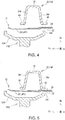
- FIG. 4 is a cross-sectional view taken along B-B in FIG. 3 .
- a jacking projection 20 that is a circular projection jutting downward is formed at a position where the front-side jacking point JPf is set.
- This jacking projection 20 serves as a mark that indicates the front-side jacking point JPf.
- a diameter of this jacking projection 20 is smaller than an inner diameter of the jack tray 104 of the garage jack 100. Thus, the jacking projection 20 is completely fitted into the jack tray 104.
- a force-bearing area 22 continues from the rear of the jacking projection 20.
- the force-bearing area 22 is an area that continues from the rear of the jacking projection 20 and opposes a lower end surface of the suspension member 14.
- a rear end edge of the jack tray 104 abuts this force-bearing area 22.
- a reaction force from the jack tray 104 is primarily applied to this force-bearing area 22. That is, when the vehicle 10 is being jacked up, as illustrated in FIG. 2 , the entire vehicle 10 including the shear plate 12 is tilted downward to the rear.
- This force-bearing area 22 is located within a force-bearing projection 24.
- the force-bearing projection 24 is a substantially rectangular projection that continues from the rear of the jacking projection 20.
- This force-bearing projection 24 is a projection that juts downward, and a jutting amount thereof is smaller than a jutting amount of the jacking projection 20. Accordingly, a step is formed between the jacking projection 20 and the force-bearing projection 24. Due to this step, the jack tray 104 is prevented from being displaced, and thus the jack tray 104 can easily abut the appropriate position.
- the shear plate 12 in order to prevent plastic deformation and damage of the shear plate 12 that are associated with jacking, it is necessary to sufficiently increase strength of the force-bearing area 22.
- thickening of the shear plate 12 is considered.
- thickening of the shear plate 12 results in an increased amount of a material and increased weight of the vehicle 10, and further leads to other problems such as increased cost and degraded fuel economy.
- the shear plate 12 is primarily arranged for the purpose of improving maneuvering stability. However, in the case where the shear plate 12 is excessively thickened, the maneuvering stability is possibly degraded.
- the shear plate 12 and the suspension member 14 are arranged at specified positions. More specifically, in this Example, as illustrated in FIG. 4 , the shear plate 12 and the suspension member 14 are arranged such that the force-bearing area 22, which opposes a part of a lower end surface of the rear cross section 32 in the suspension member 14, is arranged at the rear of the jacking projection 20.
- the rear cross section 32 has a substantially U-shaped cross section and has: paired vertical walls 36 (a front vertical wall 36f and a rear vertical wall 36r), each of which extends in a vehicle height direction; and a roof wall 38 that connects upper ends of these paired vertical walls 36.
- the rear cross section 32 further has bottom walls 40, each of which bulges outward from a lower end of the vertical wall 36.
- the force-bearing area 22 is an area that vertically opposes the lower end surface of this rear cross section 32 and continues from the rear of the jacking projection 20.
- the suspension member 14 and the shear plate 12 are arranged such that the rear vertical wall 36r is located substantially right above the force-bearing area 22.
- FIG. 4 is a cross-sectional view taken along B-B in FIG. 3 .
- FIG. 5 is a cross-sectional view at the time of jacking.
- the suspension member 14 is made of metal (for example, aluminum-based metal or the like), and thickness thereof is sufficiently greater than thickness of the shear plate 12.
- the thickness of the suspension member 14 is 5 to 20 times the thickness of the shear plate 12. Accordingly, compared to the shear plate 12, the suspension member 14 has extremely high strength and is less likely to be deformed. Since the force-bearing area 22 of the shear plate 12 contacts the lower end surface of the suspension member 14, which is unlikely to be deformed, further deformation of the force-bearing area 22 is inhibited. As a result, the shear plate 12 is inhibited from being excessively bent, and thus plastic deformation and damage of the shear plate 12 can be effectively prevented.
- the rear end edge of the jack tray 104 has to reliably abut the force-bearing area 22 (that is, the area that opposes the lower end surface of the suspension member 14).
- the jacking projection 20, which juts downward is provided at the position where the front-side jacking point JPf is set, and the step is formed around the jacking projection 20. Due to this step, significant displacement of the jack tray 104 is effectively prevented, and the position of the jack tray 104 is approximately defined.
- a rear end edge 106 of the jack tray 104 can further reliably abut the force-bearing area 22 (the area that opposes the lower end surface of the suspension member 14), and therefore plastic deformation and damage of the shear plate 12 can be more reliably inhibited.
- the vertical wall 36 of the suspension member 14 is located substantially right above the force-bearing area 22.
- deformation of the suspension member 14 and therefore plastic deformation and damage of the shear plate 12 can be more reliably inhibited. That is, of a bottom surface of the suspension member 14, a portion around each of the vertical walls 36 has particularly high strength and is thereby unlikely to be bent. Since such a vertical wall 36 is located substantially right above the force-bearing area 22, deformation of the force-bearing area 22 can also be reliably inhibited.
- the plural projections and recesses such as the jacking projection 20 and the force-bearing projection 24, are formed in the shear plate 12.
- the strength of the shear plate 12 itself is improved, and plastic deformation and damage of the shear plate 12 are further reliably prevented.
- FIG. 6 is a schematic view of the suspension member 14, the shear plate 12, and the jack tray 104.
- a diameter ⁇ p of the jacking projection 20 naturally has to be smaller than an inner diameter ⁇ i of the jack tray 104.
- the rear end edge 106 of the jack tray 104 has to abut the force-bearing area 22.
- the force-bearing area 22 is the area that continues from the rear of the jacking projection 20 and opposes the lower end surface of the suspension member 14. Accordingly, the force-bearing area 22 ranges from a rear end edge of the jacking projection 20 to a rear end of the bottom wall 40 of the suspension member 14. A longitudinal distance of this force-bearing area 22 is set as L2.
- D represents thickness of the peripheral edge of the jack tray 104. That is, in order to effectively inhibit deformation of the shear plate 12, the dimension of each of the sections is preferably set to satisfy L2 > ( ⁇ i - ⁇ p) + D.
- a user slides the garage jack 100 under the front portion of the vehicle 10 and positions the jack tray 104 substantially right under the jacking projection 20.
- the arm 102 is raised until the jack tray 104 abuts the shear plate 12.
- the position of the jack tray 104 is adjusted such that the jacking projection 20 is fitted into the jack tray 104.
- the jacking projection 20 is brought into a fitted state into the jack tray 104, the rear end edge 106 of the jack tray 104 naturally abuts the force-bearing area 22.
- the arm 102 is further raised to lift the front portion of the vehicle 10.
- a load of the vehicle 10 is applied to the rear end edge 106 of the jack tray 104, and the reaction force from the jack tray 104 is applied to the force-bearing area 22.
- the shear plate 12 is bent with the force-bearing area 22 being the center, and the force-bearing area 22 comes in contact with the bottom wall 40 of the suspension member 14. In this state, further deformation of the shear plate 12 is inhibited, and plastic deformation and damage of the shear plate 12 are effectively prevented.
- the jack tray 104 is positioned such that the jacking projection 20 is fitted into the jack tray 104, and the vehicle 10 is then jacked up.
- the area of the shear plate 12 that receives the reaction force from the jack tray 104 reliably contacts the lower end surface of the suspension member 14.
- the description so far merely constitutes one example.
- the plate material, which is formed with the jacking projection 20 has the force-bearing area 22, which continues from the rear of the jacking projection 20 and opposes the lower end surface of the frame member, other configurations may be appropriately changed.
- the rear cross section 32 (the suspension member 14) has a substantially U-shaped cross section.
- the rear cross section 32 may have a substantially square-shaped cross section that has the bottom wall 40 connecting the lower ends of the paired vertical walls 36.
- the lower end of the vertical wall 36 with high strength is desirably positioned within the area that the rear end edge 106 of the jack tray 104 abuts (the area having L1 from the rear end edge of the jacking projection 20).
- the suspension member 14 is exemplified as the frame member that the shear plate 12 contacts.
- the frame member that the shear plate 12 contacts is not limited to the suspension member 14 and may be another frame member.
- the plate material, which is formed with the jacking projection 20, may be another plate material instead of the shear plate 12.
Landscapes
- Engineering & Computer Science (AREA)
- Mechanical Engineering (AREA)
- Chemical & Material Sciences (AREA)
- Combustion & Propulsion (AREA)
- Transportation (AREA)
- Body Structure For Vehicles (AREA)
Abstract
Description
- This application claims priority to Japanese Patent Application No.
2018-035848 filed on February 28, 2018 - The present specification relates to a vehicle lower structure in which a front-side jacking point where a garage jack is received is set in a front portion of a vehicle, and to a jacking method for a vehicle.
- Normally, a jacking point is set for a vehicle. A tray of a jack (specifically, a garage jack) abuts the jacking point at the time of jacking. As such a jacking point, a front-side jacking point and a rear-side jacking point are available. The front-side jacking point is used when a front portion of the vehicle is lifted. The rear-side jacking point is used when a rear portion of the vehicle is lifted. Each of the front-side jacking point and the rear-side jacking point is set at a position where the vehicle can be lifted stably. In addition, it is designed that the jacking point has strength to endure a reaction force from the jack.
- In PATENT LITERATURE 1, a vehicle body structure for jacking is disclosed. In the vehicle body structure, a jack receiving member that receives the jack is arranged at a bottom of a rear-end cross member as a frame member of the vehicle. In PATENT LITERATURE 1, the jack receiving member has a box structure whose transverse cross section has a substantially square shape, and a bottom surface of the jack receiving member has the rear-side jacking point that the jack abuts.
- PATENT LITERATURE 1:
JP 2006-219069 A - In a technique disclosed in PATENT LITERATURE 1, it is necessary to provide a dedicated member for the jack (the jack receiving member) at the jacking point, which results in increased cost and an increased number of components. Thus, it has conventionally been proposed to set the jacking point on an existing plate material provided in the vehicle. For example, there is a case where a plate material referred to as a shear plate is arranged on a bottom surface in the front portion of the vehicle for the purpose of stabilizing maneuverability of the vehicle. Some have proposed to set the jacking point on the shear plate. With such a configuration, the dedicated member for the jack does not have to be provided, and thus the cost and the number of components can be reduced.
- In recent years, there has been a request to reduce thickness of such a plate material for the purpose of further reductions in weight and the cost of the vehicle. However, when the thickness of the plate material is reduced, there is been a case where the plate material cannot endure the reaction force from the jack at the time of jacking and is plastically deformed or damaged.
- In view of the above, the present specification discloses a vehicle lower structure capable of further inhibiting plastic deformation and damage of a plate material on which a jacking point is set while reducing thickness of the plate material, and a jacking method.
- A vehicle lower structure disclosed in the present specification includes: a plate material that is arranged on a bottom surface in a front portion of a vehicle and is formed with a jacking projection jutting downward at a position where a front-side jacking point is set; and a frame member that is arranged above the plate material. The plate material has a force-bearing area that continues from the rear of the jacking projection and vertically opposes a part of a lower end surface of the frame member.
- With such a configuration, a tray of a garage jack abuts the force-bearing area, which continues from the rear of the jacking projection. Since this force-bearing area vertically opposes the part of the lower end surface of the frame member, deformation of the force-bearing area is inhibited by the frame member. Thus, it is possible to effectively prevent excessive bending of the plate material and therefore plastic deformation and damage of the plate material. As a result, while thickening of the plate material is minimized, the plastic deformation and the damage of the plate material can be further inhibited.
- In this case, the frame member may at least have a vertical wall that extends in a vehicle height direction, and the vertical wall may be located substantially right above the force-bearing area.
- A periphery of the vertical wall is especially high in strength and is thereby unlikely to be deformed. Since such a vertical wall is located substantially right above the force-bearing area, deformation of the force-bearing area can be further effectively inhibited, and the plastic deformation and the damage of the plate material can be further inhibited.
- In addition, the plate material may further be formed with a force-bearing projection that continues from the rear of the jacking projection and juts downward by a smaller jutting amount than that of the jacking projection. The force-bearing area may be located within the force-bearing projection.
- Since the projections and recesses such as the jacking projection and the force-bearing projection are formed around the force-bearing area, strength of the plate material itself can be improved, and the plastic deformation and the damage of the plate material can be further effectively inhibited.
- The frame member may be a suspension member, and the plate material may be a shear plate, a front end of which is coupled to the suspension member and a rear end of which is coupled to another frame member or a body.
- In a configuration that members such as the suspension member and the shear plate provided in an existing vehicle receive a reaction force from the tray of the garage jack, a dedicated member does not have to be provided. Thus, cost for the vehicle can be further reduced.
- A jacking method for a vehicle disclosed in the present specification is a jacking method for jacking a vehicle using a garage jack, and the vehicle has: a plate material that is arranged at a bottom surface in a front portion of the vehicle; and a frame member that is arranged above the plate material. The plate material is formed with a jacking projection jutting downward at a position where a front-side jacking point is set. The plate material has a force-bearing area that continues from the rear of the jacking projection and vertically opposes a part of a lower end surface of the frame member. The vehicle is jacked up by causing a tray of the garage jack to abut the plate material such that the jacking projection is fitted into the tray and a peripheral edge of the tray abuts the force-bearing area.
- With such a configuration, the tray of the garage jack abuts the force-bearing area, which continues from the rear of the jacking projection. Since this force-bearing area vertically opposes the part of the lower end surface of the frame member, deformation of the force-bearing area is inhibited by the frame member. Thus, it is possible to effectively prevent excessive bending of the plate material and therefore plastic deformation and damage of the plate material. As a result, while thickening of the plate material is minimized, the plastic deformation and the damage of the plate material can be further inhibited.
- According to the vehicle lower structure and the jacking method disclosed in the present specification, the tray of the garage jack abuts the force-bearing area, which continues from the rear of the jacking projection. Since this force-bearing area vertically opposes the part of the lower end surface of the frame member, the deformation of the force-bearing area is inhibited by the frame member. Thus, it is possible to effectively prevent excessive bending of the plate material and therefore the plastic deformation and the damage of the plate material. As a result, while thickening of the plate material is minimized, the plastic deformation and the damage of the plate material can be further inhibited.
- Embodiment(s) of the present disclosure will be described based on the following figures, wherein:
-
FIG. 1 is a schematic view in which a vehicle is seen from below; -
FIG. 2 is a view of a situation where a front portion of the vehicle is jacked up; -
FIG. 3 is an enlarged view of section A inFIG. 1 ; -
FIG. 4 is a cross-sectional view taken along B-B inFIG. 3 ; -
FIG. 5 is a cross-sectional view taken along B-B at the time of jacking; -
FIG. 6 is a view illustrating a dimension of each section; and -
FIG. 7 is a view of another configuration of a suspension member. - A description will hereinafter be given of a lower structure of a
vehicle 10 with reference to the drawings.FIG. 1 is a view illustrating a jacking point of thevehicle 10 and is a schematic view in which thevehicle 10 is seen from below.FIG. 2 is a view of a situation where a front portion of thevehicle 10 is jacked up. Note thatFIG. 1 only illustrates members that are particularly related to a front-side jacking point JPf, and the other members are not illustrated. In the following drawings, Fr, R, and Up respectively mean a front direction of thevehicle 10, a right direction of thevehicle 10, and an upward direction of thevehicle 10. In the present specification, all of front, rear, left, and right of thevehicle 10 represent front, rear, left, and right that are seen from a driver. - There is a case where the
vehicle 10 is jacked up when thevehicle 10 is repaired or inspected. In the case where only one of left and right wheels is lifted, a pantograph jack is frequently used. In the case where both of the left and right wheels are lifted at the same time, agarage jack 100 is frequently used. As illustrated inFIG. 2 , thegarage jack 100 has: anarm 102 that can be raised or lowered by a hydraulic pressure or the like; and ajack tray 104 that is attached to a tip of thearm 102. Thejack tray 104 is a portion that abuts a bottom of thevehicle 10 at the time of jacking. Thisjack tray 104 usually has a substantially dish shape whose peripheral edge is raised upward. - The front-side jacking point JPf and a rear-side jacking point JPr are set on a bottom surface of the
vehicle 10. Each of the front-side jacking point JPf and a rear-side jacking point JPr is a point that thejack tray 104 of thegarage jack 100 abuts. That is, when the front portion of thevehicle 10 is jacked up, thejack tray 104 of thegarage jack 100 abuts the front-side jacking point JPf. When a rear portion of thevehicle 10 is jacked up, thejack tray 104 of thegarage jack 100 abuts the rear-side jacking point JPr. Hereinafter, a description will particularly be given of a configuration around the front-side jacking point JPf. - As is apparent from
FIG. 1 , the front-side jacking point JPf is located in the front portion of thevehicle 10 and substantially at a center in a vehicle width direction. This front-side jacking point JPf is set on a plate material referred to as ashear plate 12. That is, when the front portion of thevehicle 10 is jacked up, thejack tray 104 of thegarage jack 100 abuts theshear plate 12. - The
shear plate 12 is a plate material that is made of metal (for example, aluminum-based metal or the like). As illustrated inFIG. 1 , theshear plate 12 has a substantially trapezoidal shape, a vehicle width dimension of which is increased toward the rear. A part of thisshear plate 12 is fastened to asuspension member 14, and the other part thereof is fastened to another frame member or a body (not illustrated). With provision of such ashear plate 12, torsional rigidity of a vehicle body is improved, and maneuvering stability of thevehicle 10 is improved. The front-side jacking point JPf is set at a center of thisshear plate 12 in the vehicle width direction and near a front end thereof. - The
suspension member 14 is a frame member that supports suspension links and is also referred to as a cross member. Thesuspension member 14 in this Example has a substantially square shape and has: afront cross section 30 that extends in the vehicle width direction; arear cross section 32 that extends in the vehicle width direction behind thefront cross section 30; and pairedside sections 34 that couple both ends of thefront cross section 30 and therear cross section 32. Of these sections, therear cross section 32 traverses theshear plate 12 in the vehicle width direction at a position near the front end of theshear plate 12. - Next, a further detailed description will be given of a structure around the front-side jacking point JPf with reference to
FIG. 3 andFIG. 4 .FIG. 3 is an enlarged view of section A inFIG. 1 .FIG. 4 is a cross-sectional view taken along B-B inFIG. 3 . - In the
shear plate 12, a jackingprojection 20 that is a circular projection jutting downward is formed at a position where the front-side jacking point JPf is set. This jackingprojection 20 serves as a mark that indicates the front-side jacking point JPf. A diameter of this jackingprojection 20 is smaller than an inner diameter of thejack tray 104 of thegarage jack 100. Thus, the jackingprojection 20 is completely fitted into thejack tray 104. - A force-bearing
area 22 continues from the rear of the jackingprojection 20. The force-bearingarea 22 is an area that continues from the rear of the jackingprojection 20 and opposes a lower end surface of thesuspension member 14. When thejack tray 104 abuts theshear plate 12, a rear end edge of thejack tray 104 abuts this force-bearingarea 22. When thevehicle 10 is jacked up, a reaction force from thejack tray 104 is primarily applied to this force-bearingarea 22. That is, when thevehicle 10 is being jacked up, as illustrated inFIG. 2 , theentire vehicle 10 including theshear plate 12 is tilted downward to the rear. As a result, only the rear end edge of thejack tray 104 abuts theshear plate 12. Thus, the force-bearingarea 22, which abuts the rear end edge of thejack tray 104, receives the reaction force from thejack tray 104. - This force-bearing
area 22 is located within a force-bearingprojection 24. The force-bearingprojection 24 is a substantially rectangular projection that continues from the rear of the jackingprojection 20. This force-bearingprojection 24 is a projection that juts downward, and a jutting amount thereof is smaller than a jutting amount of the jackingprojection 20. Accordingly, a step is formed between the jackingprojection 20 and the force-bearingprojection 24. Due to this step, thejack tray 104 is prevented from being displaced, and thus thejack tray 104 can easily abut the appropriate position. - Here, in order to prevent plastic deformation and damage of the
shear plate 12 that are associated with jacking, it is necessary to sufficiently increase strength of the force-bearingarea 22. As a method of improving the strength, thickening of theshear plate 12 is considered. However, thickening of theshear plate 12 results in an increased amount of a material and increased weight of thevehicle 10, and further leads to other problems such as increased cost and degraded fuel economy. In addition, as described above, theshear plate 12 is primarily arranged for the purpose of improving maneuvering stability. However, in the case where theshear plate 12 is excessively thickened, the maneuvering stability is possibly degraded. - In view of the above, in this Example, in order to inhibit plastic deformation and damage of the
shear plate 12 associated with jacking while minimizing thickening of theshear plate 12, theshear plate 12 and thesuspension member 14 are arranged at specified positions. More specifically, in this Example, as illustrated inFIG. 4 , theshear plate 12 and thesuspension member 14 are arranged such that the force-bearingarea 22, which opposes a part of a lower end surface of therear cross section 32 in thesuspension member 14, is arranged at the rear of the jackingprojection 20. - More specifically, in this Example, the
rear cross section 32 has a substantially U-shaped cross section and has: paired vertical walls 36 (a frontvertical wall 36f and a rearvertical wall 36r), each of which extends in a vehicle height direction; and aroof wall 38 that connects upper ends of these paired vertical walls 36. Therear cross section 32 further hasbottom walls 40, each of which bulges outward from a lower end of the vertical wall 36. The force-bearingarea 22 is an area that vertically opposes the lower end surface of thisrear cross section 32 and continues from the rear of the jackingprojection 20. In addition, in this Example, thesuspension member 14 and theshear plate 12 are arranged such that the rearvertical wall 36r is located substantially right above the force-bearingarea 22. - With such a configuration, the force-bearing
area 22 is supported by the lower end surface of thesuspension member 14. Thus, the plastic deformation and the damage around the force-bearingarea 22 are effectively prevented. A description will be given of the effective prevention of plastic deformation and damage around the force-bearingarea 22 with reference toFIG. 4 and FIG. 5 . As described above,FIG. 4 is a cross-sectional view taken along B-B inFIG. 3 .FIG. 5 is a cross-sectional view at the time of jacking. - As illustrated in
FIG. 4 , before jacking, that is, in a state before thejack tray 104 abuts theshear plate 12, a slight clearance exists between theshear plate 12 and the lower end surface of thesuspension member 14, and theshear plate 12 and the lower end surface of thesuspension member 14 separate from each other. When thejack tray 104 pushes the force-bearingarea 22 from below in this state, theshear plate 12 is bent (elastically deformed) with the force-bearingarea 22 being the center and comes in contact with the lower end surface (the bottom wall 40) of thesuspension member 14. That is, a state illustrated inFIG. 5 occurs. Then, due to the contact with the lower end surface of thesuspension member 14, further deformation of the force-bearingarea 22 is inhibited. - The
suspension member 14 is made of metal (for example, aluminum-based metal or the like), and thickness thereof is sufficiently greater than thickness of theshear plate 12. For example, the thickness of thesuspension member 14 is 5 to 20 times the thickness of theshear plate 12. Accordingly, compared to theshear plate 12, thesuspension member 14 has extremely high strength and is less likely to be deformed. Since the force-bearingarea 22 of theshear plate 12 contacts the lower end surface of thesuspension member 14, which is unlikely to be deformed, further deformation of the force-bearingarea 22 is inhibited. As a result, theshear plate 12 is inhibited from being excessively bent, and thus plastic deformation and damage of theshear plate 12 can be effectively prevented. - Here, in order to prevent the plastic deformation and the damage of the
shear plate 12, the rear end edge of thejack tray 104 has to reliably abut the force-bearing area 22 (that is, the area that opposes the lower end surface of the suspension member 14). In this Example, the jackingprojection 20, which juts downward, is provided at the position where the front-side jacking point JPf is set, and the step is formed around the jackingprojection 20. Due to this step, significant displacement of thejack tray 104 is effectively prevented, and the position of thejack tray 104 is approximately defined. As a result, arear end edge 106 of thejack tray 104 can further reliably abut the force-bearing area 22 (the area that opposes the lower end surface of the suspension member 14), and therefore plastic deformation and damage of theshear plate 12 can be more reliably inhibited. - In addition, in this Example, the vertical wall 36 of the
suspension member 14 is located substantially right above the force-bearingarea 22. In this way, deformation of thesuspension member 14 and therefore plastic deformation and damage of theshear plate 12 can be more reliably inhibited. That is, of a bottom surface of thesuspension member 14, a portion around each of the vertical walls 36 has particularly high strength and is thereby unlikely to be bent. Since such a vertical wall 36 is located substantially right above the force-bearingarea 22, deformation of the force-bearingarea 22 can also be reliably inhibited. - Furthermore, in this Example, the plural projections and recesses, such as the jacking
projection 20 and the force-bearingprojection 24, are formed in theshear plate 12. By forming such projections and recesses, the strength of theshear plate 12 itself is improved, and plastic deformation and damage of theshear plate 12 are further reliably prevented. - Here, a description will be given of a dimension of each of the sections with reference to
FIG. 6. FIG. 6 is a schematic view of thesuspension member 14, theshear plate 12, and thejack tray 104. First, in order to position the jackingprojection 20 in the inside of thejack tray 104, a diameter φp of the jackingprojection 20 naturally has to be smaller than an inner diameter φi of thejack tray 104. - In addition, in order to effectively inhibit deformation of the
shear plate 12, therear end edge 106 of thejack tray 104 has to abut the force-bearingarea 22. In theshear plate 12, the force-bearingarea 22 is the area that continues from the rear of the jackingprojection 20 and opposes the lower end surface of thesuspension member 14. Accordingly, the force-bearingarea 22 ranges from a rear end edge of the jackingprojection 20 to a rear end of thebottom wall 40 of thesuspension member 14. A longitudinal distance of this force-bearingarea 22 is set as L2. Meanwhile, a range that therear end edge 106 of thejack tray 104 possibly abuts is a range having a distance L1 = (φi - φp) + D from the rear end edge of the jackingprojection 20. Note that D represents thickness of the peripheral edge of thejack tray 104. That is, in order to effectively inhibit deformation of theshear plate 12, the dimension of each of the sections is preferably set to satisfy L2 > (φi - φp) + D. - Next, a description will be given of a flow of jacking of such a
vehicle 10. In the case where it is desired to jack up the front portion of thevehicle 10, a user slides thegarage jack 100 under the front portion of thevehicle 10 and positions thejack tray 104 substantially right under the jackingprojection 20. In this state, thearm 102 is raised until thejack tray 104 abuts theshear plate 12. In the case where thejack tray 104 is displaced with respect to the jackingprojection 20 at a time point at which thejack tray 104 abuts theshear plate 12, the position of thejack tray 104 is adjusted such that the jackingprojection 20 is fitted into thejack tray 104. - Once the jacking
projection 20 is brought into a fitted state into thejack tray 104, therear end edge 106 of thejack tray 104 naturally abuts the force-bearingarea 22. In this state, thearm 102 is further raised to lift the front portion of thevehicle 10. At this time, a load of thevehicle 10 is applied to therear end edge 106 of thejack tray 104, and the reaction force from thejack tray 104 is applied to the force-bearingarea 22. When receiving this reaction force, theshear plate 12 is bent with the force-bearingarea 22 being the center, and the force-bearingarea 22 comes in contact with thebottom wall 40 of thesuspension member 14. In this state, further deformation of theshear plate 12 is inhibited, and plastic deformation and damage of theshear plate 12 are effectively prevented. - Then, when the
vehicle 10 is jacked up to desired height, a rigid rack is arranged under the lifted vehicle body. Thereafter, thearm 102 of thegarage jack 100 is gradually lowered, and the vehicle body is placed on the rigid rack. In this state, desired work (for example, tire replacement or the like) is performed. Once the required work is completed, thevehicle 10 is jacked down, and the rigid rack and thegarage jack 100 are removed from the vehicle body in reverse order from the above-described order. - As is apparent from the description so far, according to this Example, the
jack tray 104 is positioned such that the jackingprojection 20 is fitted into thejack tray 104, and thevehicle 10 is then jacked up. In this way, the area of theshear plate 12 that receives the reaction force from thejack tray 104 reliably contacts the lower end surface of thesuspension member 14. As a result, it is possible to further reliably prevent excessive bending of theshear plate 12 and therefore plastic deformation and damage of theshear plate 12. - Note that the description so far merely constitutes one example. As long as the plate material, which is formed with the jacking
projection 20, has the force-bearingarea 22, which continues from the rear of the jackingprojection 20 and opposes the lower end surface of the frame member, other configurations may be appropriately changed. For example, in the description so far, the rear cross section 32 (the suspension member 14) has a substantially U-shaped cross section. However, as illustrated inFIG. 7 , therear cross section 32 may have a substantially square-shaped cross section that has thebottom wall 40 connecting the lower ends of the paired vertical walls 36. Also, in this case, the lower end of the vertical wall 36 with high strength is desirably positioned within the area that therear end edge 106 of thejack tray 104 abuts (the area having L1 from the rear end edge of the jacking projection 20). - In addition, in the description so far, the
suspension member 14 is exemplified as the frame member that theshear plate 12 contacts. However, the frame member that theshear plate 12 contacts is not limited to thesuspension member 14 and may be another frame member. Furthermore, the plate material, which is formed with the jackingprojection 20, may be another plate material instead of theshear plate 12.
Claims (6)
- A vehicle lower structure comprising:a plate material (12) that is arranged on a bottom surface in a front portion of a vehicle and is formed with a jacking projection (20) jutting downward at a position where a front-side jacking point (JPf) is set; anda frame member (14) that is arranged above the plate material (12), whereinthe plate material (12) has a force-bearing area (22) that continues from the rear of the jacking projection (20) and vertically opposes a part of a lower end surface of the frame member (14).
- The vehicle lower structure according to claim 1, wherein
the frame member (14) at least has a vertical wall (36r) that extends in a vehicle height direction, and
the vertical wall (36r) is located substantially right above the force-bearing area (22). - The vehicle lower structure according to claim 1, wherein
the plate material (12) is further formed with a force-bearing projection (24) that continues from the rear of the jacking projection (20) and juts downward by a smaller jutting amount than that of the jacking projection (20), and
the force-bearing area (22) is located within the force-bearing projection (24). - The vehicle lower structure according to claim 2, wherein
the plate material (12) is further formed with a force-bearing projection (24) that continues from the rear of the jacking projection (20) and juts downward by a smaller jutting amount than that of the jacking projection (20), and
the force-bearing area (22) is located within the force-bearing projection (24). - The vehicle lower structure according to any one of claims 1 to 4, wherein
the frame member (14) is a suspension member (14), and
the plate material (12) is a shear plate (12), a front end of which is coupled to the suspension member (14) and a rear end of which is coupled to another frame member or a body. - A jacking method for jacking a vehicle using a garage jack (100), the vehicle having: a plate material (12) that is arranged on a bottom surface in a front portion of the vehicle; and a frame member that is arranged above the plate material (12), wherein
the plate material (12) is formed with a jacking projection (20) jutting downward at a position where a front-side jacking point (JPf) is set,
the plate material (12) has a force-bearing area (22) that continues from the rear of the jacking projection (20) and vertically opposes a part of a lower end surface of the frame member (14), and
the vehicle is jacked up by causing a tray (104) of the garage jack (100) to abut the plate material (12) such that the jacking projection (20) is fitted into the tray (104) and a peripheral edge of the tray (104) abuts the force-bearing area (22).
Applications Claiming Priority (1)
| Application Number | Priority Date | Filing Date | Title |
|---|---|---|---|
| JP2018035848A JP2019151143A (en) | 2018-02-28 | 2018-02-28 | Vehicle lower part structure and jack-up method |
Publications (3)
| Publication Number | Publication Date |
|---|---|
| EP3533671A1 true EP3533671A1 (en) | 2019-09-04 |
| EP3533671A8 EP3533671A8 (en) | 2019-10-30 |
| EP3533671B1 EP3533671B1 (en) | 2020-07-08 |
Family
ID=65529407
Family Applications (1)
| Application Number | Title | Priority Date | Filing Date |
|---|---|---|---|
| EP19158326.9A Active EP3533671B1 (en) | 2018-02-28 | 2019-02-20 | Vehicle lower structure and jacking method |
Country Status (4)
| Country | Link |
|---|---|
| US (1) | US20190263364A1 (en) |
| EP (1) | EP3533671B1 (en) |
| JP (1) | JP2019151143A (en) |
| CN (1) | CN110203177A (en) |
Families Citing this family (2)
| Publication number | Priority date | Publication date | Assignee | Title |
|---|---|---|---|---|
| EP3960722B1 (en) | 2019-08-21 | 2023-03-22 | Mitsubishi Materials Corporation | Copper/ceramic joined body, insulating circuit substrate, copper/ceramic joined body production method, and insulating circuit substrate production method |
| JP2022172544A (en) * | 2021-05-06 | 2022-11-17 | 株式会社明電舎 | Structure of jack-up point |
Citations (5)
| Publication number | Priority date | Publication date | Assignee | Title |
|---|---|---|---|---|
| US4431212A (en) * | 1980-05-29 | 1984-02-14 | Nissan Motor Company, Limited | Jacking point structure |
| JP2006219069A (en) * | 2005-02-14 | 2006-08-24 | Honda Motor Co Ltd | Vehicle body structure for jacking up |
| JP2008247120A (en) * | 2007-03-29 | 2008-10-16 | Mazda Motor Corp | Lower bodywork of vehicle |
| JP5751149B2 (en) * | 2011-11-30 | 2015-07-22 | トヨタ自動車株式会社 | Jack up structure |
| DE102015218792A1 (en) * | 2015-09-29 | 2017-03-30 | Volkswagen Aktiengesellschaft | Subframe for a motor vehicle |
Family Cites Families (6)
| Publication number | Priority date | Publication date | Assignee | Title |
|---|---|---|---|---|
| JPS63101287U (en) * | 1986-12-23 | 1988-07-01 | ||
| JPH11301522A (en) * | 1998-04-17 | 1999-11-02 | Daihatsu Motor Co Ltd | Jack support structure of vehicle |
| JP2005153798A (en) * | 2003-11-27 | 2005-06-16 | Fuji Heavy Ind Ltd | Fastening hook structure for vehicle |
| JP4771677B2 (en) * | 2004-09-21 | 2011-09-14 | スズキ株式会社 | Car body rear structure |
| US20100207428A1 (en) * | 2009-02-16 | 2010-08-19 | Mazda Motor Corporation | Side vehicle-body structure of automotive vehicle |
| WO2012093528A1 (en) * | 2011-01-07 | 2012-07-12 | 本田技研工業株式会社 | Lid-fastening structure |
-
2018
- 2018-02-28 JP JP2018035848A patent/JP2019151143A/en not_active Ceased
-
2019
- 2019-02-19 US US16/279,146 patent/US20190263364A1/en not_active Abandoned
- 2019-02-20 EP EP19158326.9A patent/EP3533671B1/en active Active
- 2019-02-22 CN CN201910131419.3A patent/CN110203177A/en active Pending
Patent Citations (5)
| Publication number | Priority date | Publication date | Assignee | Title |
|---|---|---|---|---|
| US4431212A (en) * | 1980-05-29 | 1984-02-14 | Nissan Motor Company, Limited | Jacking point structure |
| JP2006219069A (en) * | 2005-02-14 | 2006-08-24 | Honda Motor Co Ltd | Vehicle body structure for jacking up |
| JP2008247120A (en) * | 2007-03-29 | 2008-10-16 | Mazda Motor Corp | Lower bodywork of vehicle |
| JP5751149B2 (en) * | 2011-11-30 | 2015-07-22 | トヨタ自動車株式会社 | Jack up structure |
| DE102015218792A1 (en) * | 2015-09-29 | 2017-03-30 | Volkswagen Aktiengesellschaft | Subframe for a motor vehicle |
Also Published As
| Publication number | Publication date |
|---|---|
| JP2019151143A (en) | 2019-09-12 |
| CN110203177A (en) | 2019-09-06 |
| EP3533671A8 (en) | 2019-10-30 |
| US20190263364A1 (en) | 2019-08-29 |
| EP3533671B1 (en) | 2020-07-08 |
Similar Documents
| Publication | Publication Date | Title |
|---|---|---|
| EP1580099B1 (en) | Front end module assembly structure | |
| EP3533671B1 (en) | Vehicle lower structure and jacking method | |
| EP2957483B1 (en) | Suspension tower and vehicle front portion structure | |
| EP1972506A1 (en) | Underrun protector mounting structure of vehicle | |
| CN101300166A (en) | Bottom structure of vehicle body | |
| US8870261B2 (en) | Crash reinforcing member for vehicle | |
| CN103648849A (en) | Vehicle bumper reinforcement | |
| RU2362704C2 (en) | Location part for positioning of underframe in car frame, according underframe and car frame | |
| KR100907350B1 (en) | Seat for vehicle and method for releasing engagement of vehicle body and seat | |
| CN109952268B (en) | Vehicle lifting device | |
| CN104691627A (en) | Vehicle body side structure | |
| EP2653351A1 (en) | Under-run protector for vehicle | |
| CN211252807U (en) | Vehicle sub vehicle frame linking bridge | |
| EP3251770B1 (en) | Press-formed product, and production method and production equipment line for producing the press-formed product | |
| US8308215B2 (en) | Lower structure of vehicle body rear part | |
| CN115610524A (en) | Vehicle body rear structure | |
| CN104627250A (en) | Vehicle floor structure | |
| CN213262294U (en) | Mounting bracket of radar and vehicle that has it | |
| EP4360920A1 (en) | Structure component | |
| CN104228959B (en) | The structure in crossbeam portion before roof | |
| CN212555736U (en) | Automobile torsion beam | |
| JP7081717B2 (en) | In-vehicle component support structure | |
| CN114670932B (en) | Front structure of vehicle body | |
| JP6989230B2 (en) | Cargo handling equipment for forklifts | |
| CN116691842A (en) | Vehicle body rear structure |
Legal Events
| Date | Code | Title | Description |
|---|---|---|---|
| PUAI | Public reference made under article 153(3) epc to a published international application that has entered the european phase |
Free format text: ORIGINAL CODE: 0009012 |
|
| STAA | Information on the status of an ep patent application or granted ep patent |
Free format text: STATUS: REQUEST FOR EXAMINATION WAS MADE |
|
| 17P | Request for examination filed |
Effective date: 20190220 |
|
| AK | Designated contracting states |
Kind code of ref document: A1 Designated state(s): AL AT BE BG CH CY CZ DE DK EE ES FI FR GB GR HR HU IE IS IT LI LT LU LV MC MK MT NL NO PL PT RO RS SE SI SK SM TR |
|
| AX | Request for extension of the european patent |
Extension state: BA ME |
|
| RAP1 | Party data changed (applicant data changed or rights of an application transferred) |
Owner name: TOYOTA JIDOSHA KABUSHIKI KAISHA |
|
| GRAP | Despatch of communication of intention to grant a patent |
Free format text: ORIGINAL CODE: EPIDOSNIGR1 |
|
| STAA | Information on the status of an ep patent application or granted ep patent |
Free format text: STATUS: GRANT OF PATENT IS INTENDED |
|
| RIC1 | Information provided on ipc code assigned before grant |
Ipc: B62D 25/20 20060101ALI20200214BHEP Ipc: B60S 11/00 20060101AFI20200214BHEP |
|
| INTG | Intention to grant announced |
Effective date: 20200319 |
|
| GRAS | Grant fee paid |
Free format text: ORIGINAL CODE: EPIDOSNIGR3 |
|
| GRAA | (expected) grant |
Free format text: ORIGINAL CODE: 0009210 |
|
| STAA | Information on the status of an ep patent application or granted ep patent |
Free format text: STATUS: THE PATENT HAS BEEN GRANTED |
|
| RAP1 | Party data changed (applicant data changed or rights of an application transferred) |
Owner name: TOYOTA JIDOSHA KABUSHIKI KAISHA |
|
| RIN1 | Information on inventor provided before grant (corrected) |
Inventor name: YAMAMOTO, YOHEI |
|
| AK | Designated contracting states |
Kind code of ref document: B1 Designated state(s): AL AT BE BG CH CY CZ DE DK EE ES FI FR GB GR HR HU IE IS IT LI LT LU LV MC MK MT NL NO PL PT RO RS SE SI SK SM TR |
|
| REG | Reference to a national code |
Ref country code: CH Ref legal event code: EP Ref country code: AT Ref legal event code: REF Ref document number: 1288118 Country of ref document: AT Kind code of ref document: T Effective date: 20200715 |
|
| REG | Reference to a national code |
Ref country code: DE Ref legal event code: R096 Ref document number: 602019000233 Country of ref document: DE |
|
| REG | Reference to a national code |
Ref country code: IE Ref legal event code: FG4D |
|
| REG | Reference to a national code |
Ref country code: LT Ref legal event code: MG4D |
|
| REG | Reference to a national code |
Ref country code: AT Ref legal event code: MK05 Ref document number: 1288118 Country of ref document: AT Kind code of ref document: T Effective date: 20200708 |
|
| REG | Reference to a national code |
Ref country code: NL Ref legal event code: MP Effective date: 20200708 |
|
| PG25 | Lapsed in a contracting state [announced via postgrant information from national office to epo] |
Ref country code: ES Free format text: LAPSE BECAUSE OF FAILURE TO SUBMIT A TRANSLATION OF THE DESCRIPTION OR TO PAY THE FEE WITHIN THE PRESCRIBED TIME-LIMIT Effective date: 20200708 Ref country code: NO Free format text: LAPSE BECAUSE OF FAILURE TO SUBMIT A TRANSLATION OF THE DESCRIPTION OR TO PAY THE FEE WITHIN THE PRESCRIBED TIME-LIMIT Effective date: 20201008 Ref country code: BG Free format text: LAPSE BECAUSE OF FAILURE TO SUBMIT A TRANSLATION OF THE DESCRIPTION OR TO PAY THE FEE WITHIN THE PRESCRIBED TIME-LIMIT Effective date: 20201008 Ref country code: LT Free format text: LAPSE BECAUSE OF FAILURE TO SUBMIT A TRANSLATION OF THE DESCRIPTION OR TO PAY THE FEE WITHIN THE PRESCRIBED TIME-LIMIT Effective date: 20200708 Ref country code: PT Free format text: LAPSE BECAUSE OF FAILURE TO SUBMIT A TRANSLATION OF THE DESCRIPTION OR TO PAY THE FEE WITHIN THE PRESCRIBED TIME-LIMIT Effective date: 20201109 Ref country code: HR Free format text: LAPSE BECAUSE OF FAILURE TO SUBMIT A TRANSLATION OF THE DESCRIPTION OR TO PAY THE FEE WITHIN THE PRESCRIBED TIME-LIMIT Effective date: 20200708 Ref country code: AT Free format text: LAPSE BECAUSE OF FAILURE TO SUBMIT A TRANSLATION OF THE DESCRIPTION OR TO PAY THE FEE WITHIN THE PRESCRIBED TIME-LIMIT Effective date: 20200708 Ref country code: GR Free format text: LAPSE BECAUSE OF FAILURE TO SUBMIT A TRANSLATION OF THE DESCRIPTION OR TO PAY THE FEE WITHIN THE PRESCRIBED TIME-LIMIT Effective date: 20201009 Ref country code: FI Free format text: LAPSE BECAUSE OF FAILURE TO SUBMIT A TRANSLATION OF THE DESCRIPTION OR TO PAY THE FEE WITHIN THE PRESCRIBED TIME-LIMIT Effective date: 20200708 Ref country code: SE Free format text: LAPSE BECAUSE OF FAILURE TO SUBMIT A TRANSLATION OF THE DESCRIPTION OR TO PAY THE FEE WITHIN THE PRESCRIBED TIME-LIMIT Effective date: 20200708 |
|
| PG25 | Lapsed in a contracting state [announced via postgrant information from national office to epo] |
Ref country code: RS Free format text: LAPSE BECAUSE OF FAILURE TO SUBMIT A TRANSLATION OF THE DESCRIPTION OR TO PAY THE FEE WITHIN THE PRESCRIBED TIME-LIMIT Effective date: 20200708 Ref country code: LV Free format text: LAPSE BECAUSE OF FAILURE TO SUBMIT A TRANSLATION OF THE DESCRIPTION OR TO PAY THE FEE WITHIN THE PRESCRIBED TIME-LIMIT Effective date: 20200708 Ref country code: PL Free format text: LAPSE BECAUSE OF FAILURE TO SUBMIT A TRANSLATION OF THE DESCRIPTION OR TO PAY THE FEE WITHIN THE PRESCRIBED TIME-LIMIT Effective date: 20200708 Ref country code: IS Free format text: LAPSE BECAUSE OF FAILURE TO SUBMIT A TRANSLATION OF THE DESCRIPTION OR TO PAY THE FEE WITHIN THE PRESCRIBED TIME-LIMIT Effective date: 20201108 |
|
| PG25 | Lapsed in a contracting state [announced via postgrant information from national office to epo] |
Ref country code: NL Free format text: LAPSE BECAUSE OF FAILURE TO SUBMIT A TRANSLATION OF THE DESCRIPTION OR TO PAY THE FEE WITHIN THE PRESCRIBED TIME-LIMIT Effective date: 20200708 |
|
| REG | Reference to a national code |
Ref country code: DE Ref legal event code: R097 Ref document number: 602019000233 Country of ref document: DE |
|
| PG25 | Lapsed in a contracting state [announced via postgrant information from national office to epo] |
Ref country code: IT Free format text: LAPSE BECAUSE OF FAILURE TO SUBMIT A TRANSLATION OF THE DESCRIPTION OR TO PAY THE FEE WITHIN THE PRESCRIBED TIME-LIMIT Effective date: 20200708 Ref country code: SM Free format text: LAPSE BECAUSE OF FAILURE TO SUBMIT A TRANSLATION OF THE DESCRIPTION OR TO PAY THE FEE WITHIN THE PRESCRIBED TIME-LIMIT Effective date: 20200708 Ref country code: RO Free format text: LAPSE BECAUSE OF FAILURE TO SUBMIT A TRANSLATION OF THE DESCRIPTION OR TO PAY THE FEE WITHIN THE PRESCRIBED TIME-LIMIT Effective date: 20200708 Ref country code: DK Free format text: LAPSE BECAUSE OF FAILURE TO SUBMIT A TRANSLATION OF THE DESCRIPTION OR TO PAY THE FEE WITHIN THE PRESCRIBED TIME-LIMIT Effective date: 20200708 Ref country code: CZ Free format text: LAPSE BECAUSE OF FAILURE TO SUBMIT A TRANSLATION OF THE DESCRIPTION OR TO PAY THE FEE WITHIN THE PRESCRIBED TIME-LIMIT Effective date: 20200708 Ref country code: EE Free format text: LAPSE BECAUSE OF FAILURE TO SUBMIT A TRANSLATION OF THE DESCRIPTION OR TO PAY THE FEE WITHIN THE PRESCRIBED TIME-LIMIT Effective date: 20200708 |
|
| PGFP | Annual fee paid to national office [announced via postgrant information from national office to epo] |
Ref country code: FR Payment date: 20210113 Year of fee payment: 3 |
|
| PLBE | No opposition filed within time limit |
Free format text: ORIGINAL CODE: 0009261 |
|
| STAA | Information on the status of an ep patent application or granted ep patent |
Free format text: STATUS: NO OPPOSITION FILED WITHIN TIME LIMIT |
|
| PG25 | Lapsed in a contracting state [announced via postgrant information from national office to epo] |
Ref country code: AL Free format text: LAPSE BECAUSE OF FAILURE TO SUBMIT A TRANSLATION OF THE DESCRIPTION OR TO PAY THE FEE WITHIN THE PRESCRIBED TIME-LIMIT Effective date: 20200708 |
|
| PGFP | Annual fee paid to national office [announced via postgrant information from national office to epo] |
Ref country code: DE Payment date: 20210209 Year of fee payment: 3 |
|
| 26N | No opposition filed |
Effective date: 20210409 |
|
| PG25 | Lapsed in a contracting state [announced via postgrant information from national office to epo] |
Ref country code: SK Free format text: LAPSE BECAUSE OF FAILURE TO SUBMIT A TRANSLATION OF THE DESCRIPTION OR TO PAY THE FEE WITHIN THE PRESCRIBED TIME-LIMIT Effective date: 20200708 |
|
| PG25 | Lapsed in a contracting state [announced via postgrant information from national office to epo] |
Ref country code: SI Free format text: LAPSE BECAUSE OF FAILURE TO SUBMIT A TRANSLATION OF THE DESCRIPTION OR TO PAY THE FEE WITHIN THE PRESCRIBED TIME-LIMIT Effective date: 20200708 |
|
| PG25 | Lapsed in a contracting state [announced via postgrant information from national office to epo] |
Ref country code: MC Free format text: LAPSE BECAUSE OF FAILURE TO SUBMIT A TRANSLATION OF THE DESCRIPTION OR TO PAY THE FEE WITHIN THE PRESCRIBED TIME-LIMIT Effective date: 20200708 |
|
| REG | Reference to a national code |
Ref country code: BE Ref legal event code: MM Effective date: 20210228 |
|
| PG25 | Lapsed in a contracting state [announced via postgrant information from national office to epo] |
Ref country code: LU Free format text: LAPSE BECAUSE OF NON-PAYMENT OF DUE FEES Effective date: 20210220 |
|
| PG25 | Lapsed in a contracting state [announced via postgrant information from national office to epo] |
Ref country code: IE Free format text: LAPSE BECAUSE OF NON-PAYMENT OF DUE FEES Effective date: 20210220 |
|
| PG25 | Lapsed in a contracting state [announced via postgrant information from national office to epo] |
Ref country code: BE Free format text: LAPSE BECAUSE OF NON-PAYMENT OF DUE FEES Effective date: 20210228 |
|
| REG | Reference to a national code |
Ref country code: DE Ref legal event code: R119 Ref document number: 602019000233 Country of ref document: DE |
|
| REG | Reference to a national code |
Ref country code: CH Ref legal event code: PL |
|
| PG25 | Lapsed in a contracting state [announced via postgrant information from national office to epo] |
Ref country code: FR Free format text: LAPSE BECAUSE OF NON-PAYMENT OF DUE FEES Effective date: 20220228 |
|
| PG25 | Lapsed in a contracting state [announced via postgrant information from national office to epo] |
Ref country code: LI Free format text: LAPSE BECAUSE OF NON-PAYMENT OF DUE FEES Effective date: 20220228 Ref country code: DE Free format text: LAPSE BECAUSE OF NON-PAYMENT OF DUE FEES Effective date: 20220901 Ref country code: CH Free format text: LAPSE BECAUSE OF NON-PAYMENT OF DUE FEES Effective date: 20220228 |
|
| PG25 | Lapsed in a contracting state [announced via postgrant information from national office to epo] |
Ref country code: CY Free format text: LAPSE BECAUSE OF FAILURE TO SUBMIT A TRANSLATION OF THE DESCRIPTION OR TO PAY THE FEE WITHIN THE PRESCRIBED TIME-LIMIT Effective date: 20200708 |
|
| PG25 | Lapsed in a contracting state [announced via postgrant information from national office to epo] |
Ref country code: HU Free format text: LAPSE BECAUSE OF FAILURE TO SUBMIT A TRANSLATION OF THE DESCRIPTION OR TO PAY THE FEE WITHIN THE PRESCRIBED TIME-LIMIT; INVALID AB INITIO Effective date: 20190220 |
|
| GBPC | Gb: european patent ceased through non-payment of renewal fee |
Effective date: 20230220 |
|
| PG25 | Lapsed in a contracting state [announced via postgrant information from national office to epo] |
Ref country code: GB Free format text: LAPSE BECAUSE OF NON-PAYMENT OF DUE FEES Effective date: 20230220 |
|
| PG25 | Lapsed in a contracting state [announced via postgrant information from national office to epo] |
Ref country code: GB Free format text: LAPSE BECAUSE OF NON-PAYMENT OF DUE FEES Effective date: 20230220 |
|
| PG25 | Lapsed in a contracting state [announced via postgrant information from national office to epo] |
Ref country code: MK Free format text: LAPSE BECAUSE OF FAILURE TO SUBMIT A TRANSLATION OF THE DESCRIPTION OR TO PAY THE FEE WITHIN THE PRESCRIBED TIME-LIMIT Effective date: 20200708 |