EP3533509A1 - Wet abatement system - Google Patents
Wet abatement system Download PDFInfo
- Publication number
- EP3533509A1 EP3533509A1 EP19159187.4A EP19159187A EP3533509A1 EP 3533509 A1 EP3533509 A1 EP 3533509A1 EP 19159187 A EP19159187 A EP 19159187A EP 3533509 A1 EP3533509 A1 EP 3533509A1
- Authority
- EP
- European Patent Office
- Prior art keywords
- liquid
- liquid tank
- abatement system
- casing
- eductor
- Prior art date
- Legal status (The legal status is an assumption and is not a legal conclusion. Google has not performed a legal analysis and makes no representation as to the accuracy of the status listed.)
- Granted
Links
Images







Classifications
-
- B—PERFORMING OPERATIONS; TRANSPORTING
- B01—PHYSICAL OR CHEMICAL PROCESSES OR APPARATUS IN GENERAL
- B01D—SEPARATION
- B01D47/00—Separating dispersed particles from gases, air or vapours by liquid as separating agent
- B01D47/02—Separating dispersed particles from gases, air or vapours by liquid as separating agent by passing the gas or air or vapour over or through a liquid bath
- B01D47/022—Separating dispersed particles from gases, air or vapours by liquid as separating agent by passing the gas or air or vapour over or through a liquid bath by using a liquid curtain
-
- B—PERFORMING OPERATIONS; TRANSPORTING
- B01—PHYSICAL OR CHEMICAL PROCESSES OR APPARATUS IN GENERAL
- B01D—SEPARATION
- B01D53/00—Separation of gases or vapours; Recovering vapours of volatile solvents from gases; Chemical or biological purification of waste gases, e.g. engine exhaust gases, smoke, fumes, flue gases, aerosols
- B01D53/34—Chemical or biological purification of waste gases
- B01D53/74—General processes for purification of waste gases; Apparatus or devices specially adapted therefor
- B01D53/77—Liquid phase processes
- B01D53/78—Liquid phase processes with gas-liquid contact
-
- B—PERFORMING OPERATIONS; TRANSPORTING
- B01—PHYSICAL OR CHEMICAL PROCESSES OR APPARATUS IN GENERAL
- B01D—SEPARATION
- B01D47/00—Separating dispersed particles from gases, air or vapours by liquid as separating agent
- B01D47/02—Separating dispersed particles from gases, air or vapours by liquid as separating agent by passing the gas or air or vapour over or through a liquid bath
- B01D47/027—Separating dispersed particles from gases, air or vapours by liquid as separating agent by passing the gas or air or vapour over or through a liquid bath by directing the gas to be cleaned essentially tangential to the liquid surface
-
- B—PERFORMING OPERATIONS; TRANSPORTING
- B01—PHYSICAL OR CHEMICAL PROCESSES OR APPARATUS IN GENERAL
- B01D—SEPARATION
- B01D35/00—Filtering devices having features not specifically covered by groups B01D24/00 - B01D33/00, or for applications not specifically covered by groups B01D24/00 - B01D33/00; Auxiliary devices for filtration; Filter housing constructions
- B01D35/02—Filters adapted for location in special places, e.g. pipe-lines, pumps, stop-cocks
-
- B—PERFORMING OPERATIONS; TRANSPORTING
- B01—PHYSICAL OR CHEMICAL PROCESSES OR APPARATUS IN GENERAL
- B01D—SEPARATION
- B01D47/00—Separating dispersed particles from gases, air or vapours by liquid as separating agent
- B01D47/06—Spray cleaning
-
- B—PERFORMING OPERATIONS; TRANSPORTING
- B01—PHYSICAL OR CHEMICAL PROCESSES OR APPARATUS IN GENERAL
- B01D—SEPARATION
- B01D53/00—Separation of gases or vapours; Recovering vapours of volatile solvents from gases; Chemical or biological purification of waste gases, e.g. engine exhaust gases, smoke, fumes, flue gases, aerosols
- B01D53/14—Separation of gases or vapours; Recovering vapours of volatile solvents from gases; Chemical or biological purification of waste gases, e.g. engine exhaust gases, smoke, fumes, flue gases, aerosols by absorption
- B01D53/18—Absorbing units; Liquid distributors therefor
-
- B—PERFORMING OPERATIONS; TRANSPORTING
- B01—PHYSICAL OR CHEMICAL PROCESSES OR APPARATUS IN GENERAL
- B01D—SEPARATION
- B01D53/00—Separation of gases or vapours; Recovering vapours of volatile solvents from gases; Chemical or biological purification of waste gases, e.g. engine exhaust gases, smoke, fumes, flue gases, aerosols
- B01D53/34—Chemical or biological purification of waste gases
- B01D53/46—Removing components of defined structure
-
- B—PERFORMING OPERATIONS; TRANSPORTING
- B01—PHYSICAL OR CHEMICAL PROCESSES OR APPARATUS IN GENERAL
- B01D—SEPARATION
- B01D53/00—Separation of gases or vapours; Recovering vapours of volatile solvents from gases; Chemical or biological purification of waste gases, e.g. engine exhaust gases, smoke, fumes, flue gases, aerosols
- B01D53/34—Chemical or biological purification of waste gases
- B01D53/46—Removing components of defined structure
- B01D53/54—Nitrogen compounds
- B01D53/58—Ammonia
-
- B—PERFORMING OPERATIONS; TRANSPORTING
- B01—PHYSICAL OR CHEMICAL PROCESSES OR APPARATUS IN GENERAL
- B01D—SEPARATION
- B01D53/00—Separation of gases or vapours; Recovering vapours of volatile solvents from gases; Chemical or biological purification of waste gases, e.g. engine exhaust gases, smoke, fumes, flue gases, aerosols
- B01D53/34—Chemical or biological purification of waste gases
- B01D53/46—Removing components of defined structure
- B01D53/68—Halogens or halogen compounds
-
- F—MECHANICAL ENGINEERING; LIGHTING; HEATING; WEAPONS; BLASTING
- F04—POSITIVE - DISPLACEMENT MACHINES FOR LIQUIDS; PUMPS FOR LIQUIDS OR ELASTIC FLUIDS
- F04B—POSITIVE-DISPLACEMENT MACHINES FOR LIQUIDS; PUMPS
- F04B37/00—Pumps having pertinent characteristics not provided for in, or of interest apart from, groups F04B25/00 - F04B35/00
- F04B37/10—Pumps having pertinent characteristics not provided for in, or of interest apart from, groups F04B25/00 - F04B35/00 for special use
- F04B37/14—Pumps having pertinent characteristics not provided for in, or of interest apart from, groups F04B25/00 - F04B35/00 for special use to obtain high vacuum
-
- F—MECHANICAL ENGINEERING; LIGHTING; HEATING; WEAPONS; BLASTING
- F04—POSITIVE - DISPLACEMENT MACHINES FOR LIQUIDS; PUMPS FOR LIQUIDS OR ELASTIC FLUIDS
- F04B—POSITIVE-DISPLACEMENT MACHINES FOR LIQUIDS; PUMPS
- F04B39/00—Component parts, details, or accessories, of pumps or pumping systems specially adapted for elastic fluids, not otherwise provided for in, or of interest apart from, groups F04B25/00 - F04B37/00
- F04B39/06—Cooling; Heating; Prevention of freezing
-
- F—MECHANICAL ENGINEERING; LIGHTING; HEATING; WEAPONS; BLASTING
- F04—POSITIVE - DISPLACEMENT MACHINES FOR LIQUIDS; PUMPS FOR LIQUIDS OR ELASTIC FLUIDS
- F04B—POSITIVE-DISPLACEMENT MACHINES FOR LIQUIDS; PUMPS
- F04B39/00—Component parts, details, or accessories, of pumps or pumping systems specially adapted for elastic fluids, not otherwise provided for in, or of interest apart from, groups F04B25/00 - F04B37/00
- F04B39/16—Filtration; Moisture separation
-
- F—MECHANICAL ENGINEERING; LIGHTING; HEATING; WEAPONS; BLASTING
- F23—COMBUSTION APPARATUS; COMBUSTION PROCESSES
- F23G—CREMATION FURNACES; CONSUMING WASTE PRODUCTS BY COMBUSTION
- F23G7/00—Incinerators or other apparatus for consuming industrial waste, e.g. chemicals
- F23G7/06—Incinerators or other apparatus for consuming industrial waste, e.g. chemicals of waste gases or noxious gases, e.g. exhaust gases
-
- F—MECHANICAL ENGINEERING; LIGHTING; HEATING; WEAPONS; BLASTING
- F23—COMBUSTION APPARATUS; COMBUSTION PROCESSES
- F23J—REMOVAL OR TREATMENT OF COMBUSTION PRODUCTS OR COMBUSTION RESIDUES; FLUES
- F23J15/00—Arrangements of devices for treating smoke or fumes
- F23J15/02—Arrangements of devices for treating smoke or fumes of purifiers, e.g. for removing noxious material
-
- F—MECHANICAL ENGINEERING; LIGHTING; HEATING; WEAPONS; BLASTING
- F23—COMBUSTION APPARATUS; COMBUSTION PROCESSES
- F23J—REMOVAL OR TREATMENT OF COMBUSTION PRODUCTS OR COMBUSTION RESIDUES; FLUES
- F23J15/00—Arrangements of devices for treating smoke or fumes
- F23J15/02—Arrangements of devices for treating smoke or fumes of purifiers, e.g. for removing noxious material
- F23J15/022—Arrangements of devices for treating smoke or fumes of purifiers, e.g. for removing noxious material for removing solid particulate material from the gasflow
- F23J15/025—Arrangements of devices for treating smoke or fumes of purifiers, e.g. for removing noxious material for removing solid particulate material from the gasflow using filters
-
- B—PERFORMING OPERATIONS; TRANSPORTING
- B01—PHYSICAL OR CHEMICAL PROCESSES OR APPARATUS IN GENERAL
- B01D—SEPARATION
- B01D2257/00—Components to be removed
- B01D2257/20—Halogens or halogen compounds
- B01D2257/204—Inorganic halogen compounds
-
- B—PERFORMING OPERATIONS; TRANSPORTING
- B01—PHYSICAL OR CHEMICAL PROCESSES OR APPARATUS IN GENERAL
- B01D—SEPARATION
- B01D2257/00—Components to be removed
- B01D2257/40—Nitrogen compounds
- B01D2257/406—Ammonia
-
- B—PERFORMING OPERATIONS; TRANSPORTING
- B01—PHYSICAL OR CHEMICAL PROCESSES OR APPARATUS IN GENERAL
- B01D—SEPARATION
- B01D2257/00—Components to be removed
- B01D2257/55—Compounds of silicon, phosphorus, germanium or arsenic
- B01D2257/553—Compounds comprising hydrogen, e.g. silanes
-
- F—MECHANICAL ENGINEERING; LIGHTING; HEATING; WEAPONS; BLASTING
- F23—COMBUSTION APPARATUS; COMBUSTION PROCESSES
- F23G—CREMATION FURNACES; CONSUMING WASTE PRODUCTS BY COMBUSTION
- F23G2209/00—Specific waste
- F23G2209/14—Gaseous waste or fumes
- F23G2209/142—Halogen gases, e.g. silane
-
- F—MECHANICAL ENGINEERING; LIGHTING; HEATING; WEAPONS; BLASTING
- F23—COMBUSTION APPARATUS; COMBUSTION PROCESSES
- F23J—REMOVAL OR TREATMENT OF COMBUSTION PRODUCTS OR COMBUSTION RESIDUES; FLUES
- F23J2217/00—Intercepting solids
- F23J2217/50—Intercepting solids by cleaning fluids (washers or scrubbers)
-
- F—MECHANICAL ENGINEERING; LIGHTING; HEATING; WEAPONS; BLASTING
- F23—COMBUSTION APPARATUS; COMBUSTION PROCESSES
- F23J—REMOVAL OR TREATMENT OF COMBUSTION PRODUCTS OR COMBUSTION RESIDUES; FLUES
- F23J2219/00—Treatment devices
- F23J2219/40—Sorption with wet devices, e.g. scrubbers
Definitions
- the present invention relates to a wet abatement system and more particularly to a wet abatement system for detoxifying treatment gas by bringing the treatment gas into contact with liquid.
- a vacuum pump system is widely used as a piece of equipment for producing semiconductors, liquid crystals, solar panels, LEDs, or the like.
- a vacuum pump is connected to a vacuum chamber, and treatment gas introduced into the vacuum chamber is drawn out under vacuum by the vacuum pump.
- the gas drawn out under vacuum by the vacuum pump may contain toxic combustible gas such as silane gas (SiH 4 ), dichlorosilane gas (SiH 2 Cl 2 ), or ammonium gas (NH 3 ), or halogen-based non-decomposable gas such as NF 3 , ClF 3 , SF 6 , CHF 3 , C 2 F 6 , or CF 4 , which cannot be released into the atmosphere as it is.
- toxic combustible gas such as silane gas (SiH 4 ), dichlorosilane gas (SiH 2 Cl 2 ), or ammonium gas (NH 3 )
- halogen-based non-decomposable gas such as NF 3 , ClF 3 ,
- an abasement system for detoxifying toxic gas drawn out under vacuum is provided at a stage posterior to the vacuum pump.
- a detoxifying treatment of toxic gas there are known a wet detoxifying treatment in which treatment gas is brought into contact with liquid to remove foreign matters and water-soluble constituents and a combustion detoxifying treatment in which treatment gas is burnt.
- Treatment gas discharged from the vacuum pump may contain a substance solidified or a substance easy to be solidified by a reaction inside the vacuum chamber as a reaction side product.
- a reaction side product enters the abasement system, there are fears that a clogging of piping or the abasement system or a reduction in treatment efficiency of the abasement system is caused.
- a foreign matter removing mechanism for removing foreign matters is provided between the vacuum pump system and the abasement system.
- a filter or a trap can be used as such a foreign matter removing mechanism.
- the filter or the trap can remove foreign matters by its simple configuration, periodical maintenance such as a replacement of filters is necessary.
- a fan scrubber which includes a fan for stirring gas, a motor for driving the fan, and a nozzle for jetting liquid. In the fan scrubber, foreign matters are captured by the liquid jetted from the nozzle.
- the fan scrubber functions not only as the foreign matter removing mechanism but also as a wet abasement system.
- the present invention has been made in view of these problems, and an object of the present invention is to provide a wet abatement system which can suppress the accumulation of foreign matters in a treatment gas line.
- a wet abatement system for detoxifying treatment gas by bringing the treatment gas into contact with liquid.
- This wet abatement system includes an inlet casing having an inlet port from which the treatment gas is let in and an outlet port provided below the inlet port and through which the treatment gas flows, a liquid film forming device provided between the inlet port and the outlet port and configured to form a liquid film on an inner wall surface of the inlet casing, and a heater configured to heat the inlet casing and embedded in an interior of a wall portion of the inlet casing, the wall portion constituting a portion situated above the liquid film forming device.
- the liquid film is formed on the inner wall surface of the inlet casing, and the heater is embedded in the interior of the wall portion of the inlet casing which is situated above the liquid film. This allows the inlet casing to be heated to the vicinity of the inner wall surface where the liquid film is formed, thereby making it possible to prevent the accumulation of foreign matters in the treatment gas line.
- a wet abatement system of the embodiment detoxifies treatment gas by bringing the treatment gas into contact with liquid and can be made use of as a piece of equipment for producing, for example, semiconductors, liquid crystals, solar panels or LEDs.
- Fig. 1 is a drawing illustrating a schematic configuration of a wet abatement system according to an embodiment of the present invention.
- This wet abatement system 10 is provided to detoxify gas from a vacuum pump, and a vacuum pump, not shown, is connected to a primary side (upstream side) of the wet abatement system.
- the wet abatement system of the embodiment may be provided singly or may be used together with another combustion abatement system to detoxify gas from the vacuum pump.
- the wet abatement system 10 may be used singly.
- the other abatement system is preferably connected to a posterior stage to the wet abatement system 10.
- the wet abatement system 10 of the embodiment includes an inlet casing 20 into which treatment gas from the vacuum pump, not shown, is let, a liquid tank casing 40 connected to the inlet casing 20, and a treatment casing 50 connected to the liquid tank casing 40.
- Treatment gas let into the inlet casing 20 flows through the liquid tank casing 40 and the treatment casing 50 and is then discharged to an exterior of the system or is continuously introduced into another abatement system.
- the inlet casing 20 of this embodiment has a circular cylindrical shape as a whole, which is closed at an upper end while being opened at a lower end.
- the opening at the lower end of the inlet casing 20 constitutes an outlet port 24, through which treatment gas flows, and is disposed inside the liquid tank casing 40.
- An inlet port 22, which is connected to the vacuum pump, not shown, is formed in the vicinity of the upper end of the inlet casing 20. Treatment gas let into the inlet casing 20 from the inlet port 22 flows through the outlet port 24 to be guided into the liquid tank casing 40.
- a piping heater 23a is provided on an inlet piping 23 extending from the inlet port 22 towards the vacuum pump.
- the piping heater 23a heats the inlet piping 23 to a predetermined temperature (for example, 180°C) when treatment gas flows through the inlet piping 23, and various types of heaters including a jacket heater can be adopted for the piping heater 23a. Foreign matters are restrained from accumulating in the inlet piping 23 and the inlet port 22 by the piping heater 23a configured in that way.
- a predetermined temperature for example, 180°C
- a liquid film forming device 26 configured to form a liquid film (a wet wall, water fall) Lf on an inner wall surface of the inlet casing 20, is provided between the inlet port 22 and the outlet port 24 of the inlet casing 20.
- the liquid film forming device 26 is provided to extend circumferentially along a full circumference of the inlet casing 20 having an annular shape. That is, the inlet casing 20 is divided into a wall portion 31 defined above the liquid film forming device 26 and a wall portion 21 defined below the liquid film forming device 26.
- Figs. 2 to 9 illustrate configuration examples of various types of mechanisms for forming a liquid film on the inner wall surface of the wall portion 21.
- Fig. 2 is an enlarged side view of a liquid film forming device 26 illustrating a configuration as viewed from a side thereof.
- the liquid film forming device 26 of this example includes an annular liquid reservoir 28 situated adjacent to the inner wall surface of the wall portion 21, a weir 29a which continues to the wall portion 21 while projecting upwards above the liquid reservoir 28, and a liquid supply portion 27 configured to supply liquid to the liquid reservoir 28.
- a top portion of the weir 29a By leveling a top portion of the weir 29a at a uniform height, liquid overflowing from the liquid reservoir 28 flows down along the inner wall surface of the wall portion 21 to thereby form a liquid film of a uniform thickness.
- the top portion of the weir 29a has a rectangular shape; however, the top portion of the weir 29a may be rounded into a curved surface. By doing so, liquid is allowed to flow over the weir 29a more smoothly.
- Fig. 3 is a top view of the liquid film forming device 26 illustrating the configuration as viewed from a top thereof.
- liquid is preferably supplied into the liquid reservoir 28 from a tangent direction to the liquid reservoir 28. This forms a swirling flow in the liquid reservoir 28, whereby liquid flowing over the weir 29a is allowed to flow spirally.
- the level of liquid in the liquid reservoir 28 can be raised uniformly around a full circumference thereof to thereby allow liquid to flow over the weir 29a, whereby a uniform liquid film can be formed on the inner wall surface of the wall portion 21.
- the configuration is not limited thereto, and hence, one or more liquid supply portions 27 should be provided.
- Fig. 4 illustrates a modified example made to the liquid film forming device 26 illustrated in Fig. 2 .
- a top portion of a weir 29b has an L-shape in which an outer circumferential side of the top portion projects radially outwards.
- a uniform liquid film can be formed on an inner wall surface of a wall portion 21.
- the top portion of the weir 29b may be rounded into a curved surface.
- a liquid supply portion 27b preferably supplies liquid directly on to an inner wall surface of a wall portion 21.
- the liquid supply portion 27b supplies liquid in a tangent direction to the inner wall surface of the wall portion 21 so that the liquid spirally flows down along the inner wall surface.
- a uniform liquid film can be formed on the inner wall surface of the wall portion 21.
- the configuration is not limited thereto, and hence, one or more liquid supply portions 27b should be provided.
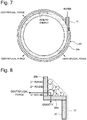
- Figs. 7 and 8 illustrate an example of a liquid film forming device including a liquid reservoir having no weir.
- liquid is supplied from a liquid supply portion 27c placed along a tangent direction to an inner surface of a side wall 28b of a liquid reservoir 28.
- Liquid supplied from the liquid supply portion 27c flows along the side wall 28b of the liquid reservoir 28 by virtue of the kinetic energy thereof. As this occurs, a centrifugal force is exerted on the liquid, and the liquid attempts to continue to flow circumferentially along a side surface of the side wall 28b as illustrated in Fig. 8 .
- purge gas is preferably supplied to an upper end portion of the liquid film formed by the liquid film forming device 26 and a circumference of the upper end portion. Air or nitrogen can be used as purge gas. Additionally, purge gas is preferably supplied after it is heated to a predetermined temperature (for example, 180°C).
- Figs. 9 and 10 illustrate an example of a purge gas supply device 25 configured to blow in purge gas.
- the purge gas supply device 25 has a short circular cylindrical shape and includes a circular groove 25g in an interior thereof.
- the purge gas supply device 25 is provided on the liquid reservoir 28 and supplies purge gas into the circular groove 25g from a plurality of nozzles 25n provided at intervals in a circumferential direction.
- Purge gas is blown into the circular groove 25g in a tangent direction to an outer circumferential surface of the circular groove 25g from the nozzles 25n, whereby the purge gas is loaded fully in the circular groove 25g along a full circumference thereof and is then blown out downwards from a full circumference of an opening 25s at a lower end of the circular groove 25g.
- the opening 25s of the purge gas supply device 25 may slope downwards towards an inner circumferential side as illustrated in Fig. 10 , or may be opened simply downwards or towards an inner circumference.
- the peripheral atmosphere of the upper end portion of the liquid film Lf and its periphery (that is, an upper end portion of a swirling flow of water formed in the liquid reservoir 28 and its vicinity) can be replaced with purge gas (air or nitrogen).
- purge gas air or nitrogen
- the number of nozzles may be the same as that of liquid supply portions 27 and can be changed as required according to the dimensions of the inlet casing 20.
- liquid can preferably be restrained from scattering.
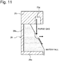
- Fig. 11 illustrates an example where the purge gas supply device 25 is used together with the liquid film forming device 26 illustrated in Figs. 7 and 8 .
- the liquid film forming device 26 includes the liquid reservoir 28 having no weir.
- the usage of the purge gas supply device 25 is not limited to the case where the purge gas supply device 25 is used together with the liquid film forming device 26 including the liquid reservoir 28 having no weir, and hence, the purge gas supply device 25 may be used together with the liquid film forming devices 26 having the other configurations illustrated in Figs. 2 to 6 .
- FIG. 1 is referred to again.
- a cartridge heater 34 is embedded in the wall portion 31 of the inlet casing 20 which is defined above the liquid film forming device 26 to heat the wall portion 31 to a predetermined temperature (for example, 180°C).
- Fig. 12 is an enlarged perspective view of the wall portion 31, and Fig. 13 illustrates an example of a cartridge heater.
- the vicinity of an upper surface portion (refer to Fig. 1 ) 32 which closes an upper end of the wall portion 31 is omitted from illustration.
- the wall portion 31 of the inlet casing 20 is formed so thick as to have a thickness of the order of 10 mm, for example.
- the wall portion 31 may be formed of the same material as or a different material from that of the wall portion 21, and a stainless steel piping can be made use of for the wall portion 31, for example. Additionally, the wall portion 31 may be thicker than the wall portion 21. Then, a vertical long hole 31a opened upwards is formed in the wall portion 31, and the cartridge heater 34 is inserted in this hole 31a.
- the cartridge heater 34 is a long heater.
- the cartridge heater 34 has a heater portion 34a inserted in the hole 31a and a wiring portion 34b connected to an external power supply.
- the wiring portion 34b is covered by an insulator 34c at a portion lying near the heater portion 34a.
- a heater having such dimensions as to be embedded in the wall portion 31 should be used as the cartridge heater 34, and hence, a known cartridge heater should be used.
- the shape of the hole 31a should be designed to match the dimensions of the cartridge heater 34.
- the number of cartridge heaters 34 can be changed as required according to the dimensions and material of the inlet casing 20, as well as the performance of the cartridge heater 34.
- the number of cartridge heaters 34 may be the same as the number of liquid supply portions 27 on the liquid film forming device 26 or the number of nozzles 25n on the purge gas supply device 25.
- the purge gas supply device 25 and the liquid film forming device 26 are located near a lower end of the wall portion 31 on an outer circumferential side thereof, and this makes it difficult to heat directly the wall portion 31 using a jacket heater. Due to this, in the inlet casing 20 of this embodiment, the wall portion 31 is formed so thick that the holes 31a are formed therein, so that the cartridge heaters 34 are inserted in the holes 31a.
- the wall portion 31 can preferably be heated to the vicinity of the liquid film forming device 26 by embedding the cartridge heaters 34 in the wall portion 31 in the way described above, whereby foreign matters can be prevented from accumulating near the liquid film forming device 26. Additionally, since the wall portion 31 is heated directly by the cartridge heaters 34 embedded in the wall portion 31, the temperature of the wall portion 31 can be increased more efficiently than using a jacket heater, whereby energy can be conserved. Further, a cartridge heater is generally less expensive than a jacket heater, whereby the cost can be reduced. Moreover, in this embodiment, since the cartridge heaters 34 are inserted into the holes 31a formed in the wall portion 31, the cartridge heaters 34 can detachably mounted in the inlet casing 20, whereby the maintenance and replacement of cartridge heaters 34 can be facilitated.
- Fig. 1 is referred to again.
- the upper end of the wall portion 31 is closed by the upper surface portion 32.
- the upper surface portion 32 may be integral with the wall portion 31 or may be fastened to the wall portion 31 with a fastening tool such as a machine screw. Additionally, holes may be formed in the upper surface portion 32 in such a manner as to communicate with the corresponding holes 31a in the wall portion 31 so that the wiring portions 34b of the cartridge heaters 34 are passed therethrough.
- the outlet port 24 of the inlet casing 20 is connected to the liquid tank casing 40.
- the liquid tank casing 40 has a liquid tank 42, and liquid flowing to form a liquid film Lf, for example, flows down into this liquid tank 42.
- the liquid tank 42 has a weir 44 located closer to the treatment casing 50 than the outlet port 24 of the inlet casing 20 and a filter 45 located closer to the treatment casing 50 than the weir 44.
- first liquid tank 42a an area held between the weir 44 and the filter 45 is referred to as a second liquid tank 42b, and an area located to the right of the filter 45 in Fig. 1 is referred to as a third liquid tank 42c.
- Liquid flowing downwards from the outlet port 24 of the inlet casing 20 temporarily enters the first liquid tank 42a. Then, the liquid reserved in the first liquid tank 42a flows over the weir 44 to flow into the second liquid tank 42b and then passes through the filter 45 to eventually flow into the third liquid tank 42c.
- a liquid outlet port 43 is provided in the third liquid tank 42c, so that the liquid within the liquid tank 42 is let out from the liquid outlet port 43.
- the liquid tank casing 40 also has a communication port 49 in an upper surface thereof, and this communication port 49 communicates with the treatment casing 50.
- the communication port 49 is preferably provided above the second liquid tank 42b.
- the outlet port 24 of the inlet casing 20 is positioned further downwards (for example, on the order of 10 mm downwards) than an upper end of the weir 44. That is, the outlet port 24 is submerged in liquid reserved in the first liquid tank 42a. Treatment gas let out from the outlet port 24 passes through the first liquid tank 42a to flow through the liquid tank casing 40 and then passes through the communication port 49 to flow into the treatment casing 50. Since the outlet port 24 of the inlet casing 20 is positioned further downwards than the upper end of the weir 44, treatment gas let out from the outlet port 24 is allowed to be brought into contact with liquid reserved in the first liquid tank 42a, thereby making it possible to remove foreign matters and water-soluble constituents contained in the treatment gas.
- the liquid tank casing 40 of this embodiment further includes an eductor 48 disposed inside the liquid tank 42.
- the eductor 48 includes a first eductor 48a provided in the first liquid tank 42a, a second eductor 48b provided in the second liquid tank 42b, and a third eductor 48c provided in the third liquid tank 42c.
- the first eductor 48a, the second eductor 48b and the third eductor 48c jet liquid downwards.
- These eductors 48a to 48c should be arranged so that liquid staying near a liquid surface of the liquid tank 42 is let therein.
- the eductor 48 also includes a fourth eductor (an outlet port eductor) 48d provided in the third liquid tank 42c and configured to jet liquid towards an interior of the liquid tank 42 from the liquid outlet port 43.
- the eductors 48a to 48d (48) are the same eductor.
- Figs. 14 and 15 are a perspective view and a sectional view, respectively, which illustrate the configuration of the eductor 48 of this embodiment.
- the eductor 48 includes a substantially circularly cylindrical main body portion 481 and a water supply portion 482 which is a circularly cylindrical portion of a smaller diameter than the main body portion 481 and into which drive water is supplied. As illustrated in Fig.
- the main body portion 481 includes a nozzle 484 made up of a small diameter hole configured to jet drive water supplied from the water supply portion 482 at a high speed, a diffusion chamber 485, an opening area of which gradually becomes wider from a lower end of the nozzle 484 towards an end thereof, and two inlet ports 483, 483 formed to face each other in a position located directly below the diffusion chamber 485.
- the eductors 48a to 48c are disposed vertically in such a manner that an inlet port 48IN formed in the water supply portion 482 is positioned upwards and an outlet port 48OUT formed in a main body portion 3a is positioned downwards.
- the fourth eductor 48d is disposed in such a manner that the outlet port 48OUT is positioned in a direction in which the outlet port 48OUT lies away from the liquid outlet port 43.
- the inside diameter d1 is 19.6 mm
- the diameter d2 of the inlet port 483 is 17 mm
- the bore diameter d3 of the nozzle 484 is 4.2 mm
- an outside diameter of the main body portion 481 is 24 mm
- the length 1b of the main body portion 481 is 59 mm.
- An overall length of the eductor 48 including the main body portion 481 and the water supply portion 482 is 72 mm, and a resin material such as PVC is used as a material for the eductor 48.
- the structure of the eductor 48 is extremely simple, and the eductor 48 is a unit which is small in size, light in weight, and inexpensive in cost.
- Fig. 16 is a schematic drawing explaining the function of the eductor 48 of this embodiment.
- Drive water supplied from the inlet port 48IN of the water supply portion 482 is throttled by the nozzle 484 as indicated by white arrows and is jetted into the diffusion chamber 485 at high speeds.
- the pressure inside the diffusion chamber 485 is reduced by a flow of drive water jetted into the diffusion chamber 485 at high speeds, whereby liquid in the liquid tank 42 is let into the diffusion chamber 485 from the two inlet ports 483, 483 as indicated by black arrows.
- Water let into the diffusion chamber 485 from the inlet ports 483, 483 is let out from the outlet port 48OUT together with drive water which flows in from the water supply portion 482.
- a quantity of water supplied from the water supply portion 482 is referred to as Q
- a quantity of water let in from the two inlet ports 483, 483 is approximately 4Q, and hence, in total, a quantity of liquid corresponding to 5Q is jetted from the eductor 48.
- Liquid in the liquid tank 42 can be stirred by the eductor 48 configured in the way described above. This can prevent foreign matters from accumulating at a liquid surface of the liquid tank 42.
- constituents contained in treatment gas stay in the liquid tank 42 without being oxidized sufficiently. These insufficiently oxidized constituents can be oxidized completely by stirring the liquid in the liquid tank 42 by the eductor 48, whereby an unintended environment can be restrained from being generated in the liquid tank casing 40.
- the fourth eductor 48d jets liquid in a direction in which the liquid moves away from the liquid outlet port 43. This prevents the liquid outlet port 43 being clogged.
- the liquid tank casing 40 has a nozzle 46 configured to jet liquid against treatment gas flowing inside the liquid tank casing 40. While liquid is preferably dispersed everywhere inside the liquid tank casing 40 by the nozzle 46, the number and arrangement of nozzles 46 should be determined as required based on the dimensions of the liquid tank casing 40. Treatment gas is brought into contact with liquid by jetting liquid against the treatment gas from the nozzle 46, whereby foreign matters and water-soluble constituents contained in the treatment gas can be removed.
- the wet abatement system 10 of this embodiment includes a pump 60 configured to send liquid let out from the liquid outlet port 43 of the liquid tank 42 under pressure.
- a removing mechanism (not shown) for removing foreign matters contained in liquid may be provided on a liquid flow path 61 connected to the pump 60.
- the pump 60 supplies liquid let out from the liquid outlet port 43 to at least one of the liquid supply portion 27 of the inlet casing 20, the nozzle 46 of the liquid tank casing 40, the water supply portion 482 of the eductor 48, and fan scrubber 56 of the treatment casing 50. Since liquid reserved in the liquid tank 42 is reused, not only can the running cost of the wet abatement system 10 be reduced, but also the wet abatement system 10 can contribute to preservation of the environment.
- the pump 60 should be able to discharge part of liquid let out from the liquid outlet port 43 to an exterior of the system.
- the pump 60 should be controlled to keep the level of liquid in the liquid tank 42 (for example, the second liquid tank 42b) within a predetermined range (a range from a predetermined first threshold or higher to lower than a predetermined second threshold) based on a level meter (not shown) provided in the liquid tank 42 (for example, the second liquid tank 42b).
- the treatment casing 50 has a flow path 52 extending upwards from the communication port 49 of the liquid tank casing 40 and a treatment chamber 54 accommodating the fan scrubber 56.
- the treatment chamber 54 has a gas outlet port 57 through which detoxified treatment gas flows and a liquid outlet port 58 from which liquid is let out.
- the treatment casing 50 has a nozzle 56a configured to supply liquid to the fan scrubber 56 and a nozzle 59 configured to supply liquid to the flow path 52 and the gas outlet port 57.
- liquid (recirculation liquid) reserved in the liquid tank 42 is supplied to the nozzle 56a through the pump 60, and fresh water (industrial water or the like) is supplied to the nozzle 59 from a supply portion, not shown.
- circulation water may be used for all the various types of liquid used in the wet abatement system 10, or fresh water may be used instead.
- the fan scrubber 56 removes foreign matters and water-soluble constituents contained in treatment gas by rotating a fan to stir the treatment gas and liquid. Since a known device can be used for the fan scrubber 56 and the fan scrubber 56 does not constitute the gist of the present invention, a detailed description of the fan scrubber 56 is omitted herein.
- Treatment gas having passed through the treatment chamber 54 passes through the gas outlet port 57 to be let out to an exterior of the system or to be guided to another abatement system.
- Liquid inside the treatment chamber 54 passes through the liquid outlet port 58 and is then let out from the treatment chamber 54.
- the liquid outlet port 58 is connected to the liquid tank casing 40, and the liquid let out from the treatment chamber 54 flows downwards into the liquid tank 42.
- the liquid outlet port 58 is connected to the liquid tank casing 40 above the third liquid tank 42c in Fig. 1 , the liquid outlet port 58 may be connected to the liquid tank casing 40 above the second liquid tank 42b or the first liquid tank 42a.
- This wet abatement system includes an inlet casing having an inlet port from which the treatment gas is let in and an outlet port provided below the inlet port and through which the treatment gas flows, a liquid film forming device provided between the inlet port and the outlet port and configured to form a liquid film on an inner wall surface of the inlet casing, and a heater configured to heat the inlet casing and embedded in an interior of a wall portion of the inlet casing, the wall portion constituting a portion situated above the liquid film forming device.
- the liquid film is formed on the inner wall surface of the inlet casing, and the heater is embedded in the interior of the wall portion of the inlet casing which is situated above the liquid film. This allows the inlet casing to be heated to the vicinity of the inner wall surface where the liquid film is formed, thereby making it possible to prevent the accumulation of foreign matters in the treatment gas line.
- a vertical hole is formed in the wall portion of the inlet casing, and the heater is a cartridge heater inserted in the hole.
- the wet abatement system can be configured simple, and the replacement and maintenance of heaters can be facilitated.
- the heater is positioned on an inner circumferential side of at least part of the liquid film forming device.
- the vicinity of the liquid film forming device can be heated by the heater, whereby foreign matters can be restrained from accumulating in the inlet casing.
- the liquid film forming device has an annular liquid reservoir lying adjacent to an inner wall surface of the inlet casing.
- the wet abatement system of any one of the first to fourth modes further includes a purge gas supply device configured to blow purge gas towards an upper end portion of the liquid film and a circumference of the upper end portion.
- the wet abatement system of any one of the first to sixth modes includes a liquid tank casing connected to the outlet port of the inlet casing and having a liquid tank where to reserve liquid supplied by the liquid film forming device, a treatment casing connected to the liquid tank casing, and a fan scrubber provided inside the treatment casing.
- the liquid tank has a weir configured to allow overflowing liquid to flow to a downstream side, and the outlet port of the inlet casing is positioned below an upper end of the weir.
- treatment gas flowing out of the outlet port of the inlet casing can be brought into contact with liquid reserved in the liquid tank, thereby making it possible to remove foreign matters and water-soluble constituents contained in the treatment gas.
- the wet abatement system of the seventh or eighth mode further includes an eductor provided inside the liquid tank and configured to stir liquid reserved in the liquid tank.
- the wet abatement system of any one of the seventh to ninth modes further includes an eductor provided inside the liquid tank and configured to stir liquid reserved in the liquid tank, and the liquid tank has a weir configured to allow overflowing liquid to flow to a downstream side, and a filter provided at the downstream side of the weir, and the eductor has a first eductor provided in a first liquid tank defined further upstream than the weir in the liquid tank, a second eductor provided in a second liquid tank defined between the weir and the filter, and a third eductor provided in a third liquid tank defined further downstream than the filter, the first eductor, the second eductor and the third eductor jetting liquid downwards.
- the liquid tank has a liquid outlet port configured to let liquid reserved in the liquid tank out, and an outlet port eductor configured to jet liquid from the liquid outlet port towards an interior of the liquid tank is provided in the liquid tank.
- the liquid outlet port can be restrained from clogging.
- the wet abatement system of any one of the seventh to eleventh modes further includes a pump configured to send liquid reserved in the liquid tank to at least one of the liquid film forming device and the fan scrubber.
- the wet abatement system of the twelfth mode further includes a nozzle configured to jet liquid against treatment gas passing through the liquid tank casing, and the pump supplies liquid to the nozzle.
- the treatment gas passing through the liquid tank casing and the liquid can be brought into contact with each other, thereby making it possible to remove foreign matters and water-soluble constituents contained in the treatment gas.
Landscapes
- Engineering & Computer Science (AREA)
- Chemical & Material Sciences (AREA)
- Chemical Kinetics & Catalysis (AREA)
- Environmental & Geological Engineering (AREA)
- Oil, Petroleum & Natural Gas (AREA)
- General Chemical & Material Sciences (AREA)
- Analytical Chemistry (AREA)
- Biomedical Technology (AREA)
- Health & Medical Sciences (AREA)
- General Engineering & Computer Science (AREA)
- Mechanical Engineering (AREA)
- Treating Waste Gases (AREA)
- Separation Of Particles Using Liquids (AREA)
- Compressors, Vaccum Pumps And Other Relevant Systems (AREA)
- Gas Separation By Absorption (AREA)
Abstract
Description
- The present invention relates to a wet abatement system and more particularly to a wet abatement system for detoxifying treatment gas by bringing the treatment gas into contact with liquid.
- A vacuum pump system is widely used as a piece of equipment for producing semiconductors, liquid crystals, solar panels, LEDs, or the like. In a fabrication process of such products, a vacuum pump is connected to a vacuum chamber, and treatment gas introduced into the vacuum chamber is drawn out under vacuum by the vacuum pump. The gas drawn out under vacuum by the vacuum pump may contain toxic combustible gas such as silane gas (SiH4), dichlorosilane gas (SiH2Cl2), or ammonium gas (NH3), or halogen-based non-decomposable gas such as NF3, ClF3, SF6, CHF3, C2F6, or CF4, which cannot be released into the atmosphere as it is. To cope with this, in the vacuum pump system, conventionally, an abasement system for detoxifying toxic gas drawn out under vacuum is provided at a stage posterior to the vacuum pump. As a detoxifying treatment of toxic gas, there are known a wet detoxifying treatment in which treatment gas is brought into contact with liquid to remove foreign matters and water-soluble constituents and a combustion detoxifying treatment in which treatment gas is burnt.
- Treatment gas discharged from the vacuum pump may contain a substance solidified or a substance easy to be solidified by a reaction inside the vacuum chamber as a reaction side product. When such a reaction side product enters the abasement system, there are fears that a clogging of piping or the abasement system or a reduction in treatment efficiency of the abasement system is caused. To cope with this, there is a case a foreign matter removing mechanism for removing foreign matters is provided between the vacuum pump system and the abasement system.
- For example, a filter or a trap can be used as such a foreign matter removing mechanism. Although the filter or the trap can remove foreign matters by its simple configuration, periodical maintenance such as a replacement of filters is necessary. Additionally, as a foreign matter removing mechanism, there is also known a fan scrubber, which includes a fan for stirring gas, a motor for driving the fan, and a nozzle for jetting liquid. In the fan scrubber, foreign matters are captured by the liquid jetted from the nozzle. The fan scrubber functions not only as the foreign matter removing mechanism but also as a wet abasement system.
- PTL 1: Japanese Patent Laid-Open No.
2003-251130 - In the conventional foreign matter removing mechanism or abasement system, there may be situations where foreign matters such as a condensable product accumulate in piping situated upstream of a section where the removal or abatement function is exhibited. To prevent the accumulation of foreign matters in the piping, the piping is heated, a wet wall (a liquid surface) is formed on the piping, or a scraper is used to mechanically scrape the accumulated foreign matters. Here, when the piping is heated, it is desirable that the piping is heated to a high temperature of 150°C or higher, for example. In the wet abatement system, however, the temperature of the piping is decreased by the liquid in the vicinity of the area where the liquid is supplied, whereby foreign matters accumulate near the area from time to time. Additionally, in the case of the wet wall being formed, too, foreign matters such as a condensable product accumulate on an upstream side of the wet wall, or a reaction product of water-soluble gas such as dichlorosilane gas (SiH2Cl2) with water accumulates at the liquid supply portion for forming the wet wall. Some reaction products produced from the reaction of such a water-soluble gas with water produce an unstable reaction product where the reaction has not yet been completed, for example, a highly reactive siloxane mixture that produces hydrogen from time to time. When foreign matters are removed by the scraper near the area where the liquid is supplied, there occurs a known risk of hydrogen being ignited by static electricity generated by friction.
- The present invention has been made in view of these problems, and an object of the present invention is to provide a wet abatement system which can suppress the accumulation of foreign matters in a treatment gas line.
- According an embodiment of the present invention, there is proposed a wet abatement system for detoxifying treatment gas by bringing the treatment gas into contact with liquid. This wet abatement system includes an inlet casing having an inlet port from which the treatment gas is let in and an outlet port provided below the inlet port and through which the treatment gas flows, a liquid film forming device provided between the inlet port and the outlet port and configured to form a liquid film on an inner wall surface of the inlet casing, and a heater configured to heat the inlet casing and embedded in an interior of a wall portion of the inlet casing, the wall portion constituting a portion situated above the liquid film forming device.
- According to the wet abatement system described above, the liquid film is formed on the inner wall surface of the inlet casing, and the heater is embedded in the interior of the wall portion of the inlet casing which is situated above the liquid film. This allows the inlet casing to be heated to the vicinity of the inner wall surface where the liquid film is formed, thereby making it possible to prevent the accumulation of foreign matters in the treatment gas line.
-
Fig. 1 is a drawing illustrating a schematic configuration of a wet abatement system according to an embodiment; -
Fig. 2 is an enlarged side view of a liquid film forming device illustrating a configuration thereof as viewed from a side thereof; -
Fig. 3 is a top view of the liquid film forming device illustrating the configuration as viewed from a top thereof; -
Fig. 4 is a drawing illustrating a modified example made to the liquid film forming device illustrated inFig. 2 ; -
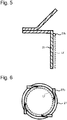
Fig. 5 is a side view of an example of a liquid film forming device having no liquid reservoir as viewed from a side thereof; -
Fig. 6 is a top view of the example of the liquid film forming device having no liquid reservoir as viewed from a top thereof; -
Fig. 7 is a top view of an example of a liquid film forming device including a liquid reservoir having no weir as viewed from a top thereof; -
Fig. 8 is an enlarged side view of the example of the liquid film forming device including the liquid reservoir having no weir as viewed from a side thereof; -
Fig. 9 is a top view of an example of a purge gas supply device for blowing in purge gas as viewed from a top thereof; -
Fig. 10 is a side view of the example of the purge gas supply device for blowing in purge gas as viewed from a side thereof; -
Fig. 11 is a drawing illustrating an example in which the purge gas supply device is used together with the liquid film forming device illustrated inFigs. 7 and 8 ; -
Fig. 12 is an enlarged perspective view of a wall portion of the inlet casing situated above the liquid film forming device; -
Fig. 13 is a drawing illustrating an example of a cartridge heater; -
Fig. 14 is a perspective view illustrating the configuration of an eductor of the embodiment; -
Fig. 15 is a sectional view showing the configuration of the eductor of the embodiment; and -
Fig. 16 is a schematic drawing explaining the function of the eductor of the embodiment. - Hereinafter, referring to drawings, an embodiment of the present invention will be described. In the following description, in the drawings, like reference signs will be given to like or corresponding configuration elements, so that similar descriptions are not made repeatedly. A wet abatement system of the embodiment detoxifies treatment gas by bringing the treatment gas into contact with liquid and can be made use of as a piece of equipment for producing, for example, semiconductors, liquid crystals, solar panels or LEDs.
-
Fig. 1 is a drawing illustrating a schematic configuration of a wet abatement system according to an embodiment of the present invention. Thiswet abatement system 10 is provided to detoxify gas from a vacuum pump, and a vacuum pump, not shown, is connected to a primary side (upstream side) of the wet abatement system. The wet abatement system of the embodiment may be provided singly or may be used together with another combustion abatement system to detoxify gas from the vacuum pump. For example, in the case where all removal target gas that is contained in gas drawn out under vacuum by the vacuum pump is made up of water-soluble constituents, thewet abatement system 10 may be used singly. When thewet abatement system 10 is used together with another abatement system, the other abatement system is preferably connected to a posterior stage to thewet abatement system 10. - As illustrated in
Fig. 1 , thewet abatement system 10 of the embodiment includes aninlet casing 20 into which treatment gas from the vacuum pump, not shown, is let, aliquid tank casing 40 connected to theinlet casing 20, and atreatment casing 50 connected to theliquid tank casing 40. Treatment gas let into theinlet casing 20 flows through theliquid tank casing 40 and thetreatment casing 50 and is then discharged to an exterior of the system or is continuously introduced into another abatement system. - The
inlet casing 20 of this embodiment has a circular cylindrical shape as a whole, which is closed at an upper end while being opened at a lower end. The opening at the lower end of theinlet casing 20 constitutes an outlet port 24, through which treatment gas flows, and is disposed inside theliquid tank casing 40. Aninlet port 22, which is connected to the vacuum pump, not shown, is formed in the vicinity of the upper end of theinlet casing 20. Treatment gas let into theinlet casing 20 from theinlet port 22 flows through the outlet port 24 to be guided into theliquid tank casing 40. Apiping heater 23a is provided on aninlet piping 23 extending from theinlet port 22 towards the vacuum pump. Thepiping heater 23a heats theinlet piping 23 to a predetermined temperature (for example, 180°C) when treatment gas flows through theinlet piping 23, and various types of heaters including a jacket heater can be adopted for thepiping heater 23a. Foreign matters are restrained from accumulating in theinlet piping 23 and theinlet port 22 by thepiping heater 23a configured in that way. - A liquid
film forming device 26, configured to form a liquid film (a wet wall, water fall) Lf on an inner wall surface of theinlet casing 20, is provided between theinlet port 22 and the outlet port 24 of theinlet casing 20. In this embodiment, the liquidfilm forming device 26 is provided to extend circumferentially along a full circumference of theinlet casing 20 having an annular shape. That is, theinlet casing 20 is divided into awall portion 31 defined above the liquidfilm forming device 26 and awall portion 21 defined below the liquidfilm forming device 26. By forming a liquid film Lf on the inner wall surface using the liquidfilm forming device 26, foreign matters are caused to flow down near the inner wall surface of thewall portion 21 by the liquid film so formed, whereby foreign matters are restrained from accumulating on thewall portion 21. -
Figs. 2 to 9 illustrate configuration examples of various types of mechanisms for forming a liquid film on the inner wall surface of thewall portion 21. -
Fig. 2 is an enlarged side view of a liquidfilm forming device 26 illustrating a configuration as viewed from a side thereof. The liquidfilm forming device 26 of this example includes anannular liquid reservoir 28 situated adjacent to the inner wall surface of thewall portion 21, aweir 29a which continues to thewall portion 21 while projecting upwards above theliquid reservoir 28, and aliquid supply portion 27 configured to supply liquid to theliquid reservoir 28. By leveling a top portion of theweir 29a at a uniform height, liquid overflowing from theliquid reservoir 28 flows down along the inner wall surface of thewall portion 21 to thereby form a liquid film of a uniform thickness. In the example illustrated inFig. 2 , the top portion of theweir 29a has a rectangular shape; however, the top portion of theweir 29a may be rounded into a curved surface. By doing so, liquid is allowed to flow over theweir 29a more smoothly. -
Fig. 3 is a top view of the liquidfilm forming device 26 illustrating the configuration as viewed from a top thereof. As illustrated inFig. 3 , liquid is preferably supplied into theliquid reservoir 28 from a tangent direction to theliquid reservoir 28. This forms a swirling flow in theliquid reservoir 28, whereby liquid flowing over theweir 29a is allowed to flow spirally. By generating a swirling flow in theliquid reservoir 28, the level of liquid in theliquid reservoir 28 can be raised uniformly around a full circumference thereof to thereby allow liquid to flow over theweir 29a, whereby a uniform liquid film can be formed on the inner wall surface of thewall portion 21. In the example illustrated inFig. 3 , although fourliquid supply portions 27 are provided, the configuration is not limited thereto, and hence, one or moreliquid supply portions 27 should be provided. -
Fig. 4 illustrates a modified example made to the liquidfilm forming device 26 illustrated inFig. 2 . A top portion of a weir 29b has an L-shape in which an outer circumferential side of the top portion projects radially outwards. In this example, too, it is considered that a uniform liquid film can be formed on an inner wall surface of awall portion 21. In this case, too, the top portion of the weir 29b may be rounded into a curved surface. - In the examples illustrated in
Figs. 2 to 4 , although the liquidfilm forming device 26 is described as having theliquid reservoir 28, the liquidfilm forming device 26 may not have theliquid reservoir 28.Figs. 5 and 6 illustrate an example of a liquidfilm forming device 26 having no liquid reservoir. In the example illustrated inFigs. 5 and 6 , aliquid supply portion 27b preferably supplies liquid directly on to an inner wall surface of awall portion 21. Here, as illustrated inFig. 6 , theliquid supply portion 27b supplies liquid in a tangent direction to the inner wall surface of thewall portion 21 so that the liquid spirally flows down along the inner wall surface. In this example, too, it is considered that a uniform liquid film can be formed on the inner wall surface of thewall portion 21. In the example illustrated inFig. 6 , although fourliquid supply portions 27b are provided, the configuration is not limited thereto, and hence, one or moreliquid supply portions 27b should be provided. - In addition, the
weirs 29a, 29b may not be provided in theliquid reservoir 28 of the liquidfilm forming device 26.Figs. 7 and 8 illustrate an example of a liquid film forming device including a liquid reservoir having no weir. As illustrated inFig. 7 , liquid is supplied from a liquid supply portion 27c placed along a tangent direction to an inner surface of aside wall 28b of aliquid reservoir 28. Liquid supplied from the liquid supply portion 27c flows along theside wall 28b of theliquid reservoir 28 by virtue of the kinetic energy thereof. As this occurs, a centrifugal force is exerted on the liquid, and the liquid attempts to continue to flow circumferentially along a side surface of theside wall 28b as illustrated inFig. 8 . On the other hand, since liquid continues to be supplied from the liquid supply portion 27c, in the liquid flowing circumferentially on theside wall 28b, a circumferential flow of liquid that has flowed a full circumference of theside wall 28b three times is raised upwards by a circumferential flow of liquid that has flowed a full circumference of theside wall 28b twice, which is raised upwards by a circumferential flow of liquid that has flowed a full circumference of theside wall 28b once. In this way, a circumferential flow of liquid that continues to flow circumferentially more times is raised upwards by a circumferential flow of liquid that continues to flow circumferentially fewer times. However, as the number of times the liquid flows a full circumference of theside wall 28b increases, the kinetic energy of the liquid is reduced due to friction, and at the same time, the centrifugal force exerted on the liquid is weakened, whereby the liquid raised upwards flows downwards circumferentially inwards by gravity. This forms a liquid film having a liquid plane sloping downwards from a circumferentially outer side towards a circumferentially inner side. Then, the liquid flows falling down along an inner wall surface of awall portion 21 from an inner edge of abottom plate 28a of theliquid reservoir 28, whereby a liquid film (a wet wall) Lf is formed on the inner wall surface of thewall portion 21. - Further, purge gas is preferably supplied to an upper end portion of the liquid film formed by the liquid
film forming device 26 and a circumference of the upper end portion. Air or nitrogen can be used as purge gas. Additionally, purge gas is preferably supplied after it is heated to a predetermined temperature (for example, 180°C). -
Figs. 9 and 10 illustrate an example of a purgegas supply device 25 configured to blow in purge gas. In the example illustrated inFigs. 9 and 10 , the purgegas supply device 25 has a short circular cylindrical shape and includes acircular groove 25g in an interior thereof. The purgegas supply device 25 is provided on theliquid reservoir 28 and supplies purge gas into thecircular groove 25g from a plurality ofnozzles 25n provided at intervals in a circumferential direction. Purge gas is blown into thecircular groove 25g in a tangent direction to an outer circumferential surface of thecircular groove 25g from thenozzles 25n, whereby the purge gas is loaded fully in thecircular groove 25g along a full circumference thereof and is then blown out downwards from a full circumference of anopening 25s at a lower end of thecircular groove 25g. Theopening 25s of the purgegas supply device 25 may slope downwards towards an inner circumferential side as illustrated inFig. 10 , or may be opened simply downwards or towards an inner circumference. By blowing out purge gas into an annular shape from thecircular groove 25g in the way described above, the peripheral atmosphere of the upper end portion of the liquid film Lf and its periphery (that is, an upper end portion of a swirling flow of water formed in theliquid reservoir 28 and its vicinity) can be replaced with purge gas (air or nitrogen). In the example illustrated inFig. 9 , while twonozzles 25n are provided, the number of nozzles may be the same as that ofliquid supply portions 27 and can be changed as required according to the dimensions of theinlet casing 20. - When providing the purge
gas supply device 25, by configuring the liquidfilm forming device 26 as illustrated inFigs. 7 and 8 , liquid can preferably be restrained from scattering.Fig. 11 illustrates an example where the purgegas supply device 25 is used together with the liquidfilm forming device 26 illustrated inFigs. 7 and 8 . As described above, the liquidfilm forming device 26 includes theliquid reservoir 28 having no weir. When purge gas is blown against a liquid film Lf formed by the liquidfilm forming device 26 configured in that way, part of the liquid film Lf is only dented, and the flow of liquid is not interrupted, whereby the scattering of liquid can preferably be restrained. However, the usage of the purgegas supply device 25 is not limited to the case where the purgegas supply device 25 is used together with the liquidfilm forming device 26 including theliquid reservoir 28 having no weir, and hence, the purgegas supply device 25 may be used together with the liquidfilm forming devices 26 having the other configurations illustrated inFigs. 2 to 6 . -
Fig. 1 is referred to again. Acartridge heater 34 is embedded in thewall portion 31 of theinlet casing 20 which is defined above the liquidfilm forming device 26 to heat thewall portion 31 to a predetermined temperature (for example, 180°C).Fig. 12 is an enlarged perspective view of thewall portion 31, andFig. 13 illustrates an example of a cartridge heater. InFig. 12 , the vicinity of an upper surface portion (refer toFig. 1 ) 32 which closes an upper end of thewall portion 31 is omitted from illustration. As illustrated inFig. 12 , thewall portion 31 of theinlet casing 20 is formed so thick as to have a thickness of the order of 10 mm, for example. Thewall portion 31 may be formed of the same material as or a different material from that of thewall portion 21, and a stainless steel piping can be made use of for thewall portion 31, for example. Additionally, thewall portion 31 may be thicker than thewall portion 21. Then, a verticallong hole 31a opened upwards is formed in thewall portion 31, and thecartridge heater 34 is inserted in thishole 31a. Thecartridge heater 34 is a long heater. Thecartridge heater 34 has aheater portion 34a inserted in thehole 31a and awiring portion 34b connected to an external power supply. Thewiring portion 34b is covered by aninsulator 34c at a portion lying near theheater portion 34a. A heater having such dimensions as to be embedded in thewall portion 31 should be used as thecartridge heater 34, and hence, a known cartridge heater should be used. The shape of thehole 31a should be designed to match the dimensions of thecartridge heater 34. In the example illustrated inFig. 12 , while sixcartridge heaters 34 are provided at certain intervals in a circumferential direction of thewall portion 31, the number ofcartridge heaters 34 can be changed as required according to the dimensions and material of theinlet casing 20, as well as the performance of thecartridge heater 34. For example, the number ofcartridge heaters 34 may be the same as the number ofliquid supply portions 27 on the liquidfilm forming device 26 or the number ofnozzles 25n on the purgegas supply device 25. - To increase an interior surface temperature of the piping, it is general practice to use a jacket heater on an outer side of the piping. In this embodiment, however, the purge
gas supply device 25 and the liquidfilm forming device 26 are located near a lower end of thewall portion 31 on an outer circumferential side thereof, and this makes it difficult to heat directly thewall portion 31 using a jacket heater. Due to this, in the inlet casing 20 of this embodiment, thewall portion 31 is formed so thick that theholes 31a are formed therein, so that thecartridge heaters 34 are inserted in theholes 31a. Thewall portion 31 can preferably be heated to the vicinity of the liquidfilm forming device 26 by embedding thecartridge heaters 34 in thewall portion 31 in the way described above, whereby foreign matters can be prevented from accumulating near the liquidfilm forming device 26. Additionally, since thewall portion 31 is heated directly by thecartridge heaters 34 embedded in thewall portion 31, the temperature of thewall portion 31 can be increased more efficiently than using a jacket heater, whereby energy can be conserved. Further, a cartridge heater is generally less expensive than a jacket heater, whereby the cost can be reduced. Moreover, in this embodiment, since thecartridge heaters 34 are inserted into theholes 31a formed in thewall portion 31, thecartridge heaters 34 can detachably mounted in theinlet casing 20, whereby the maintenance and replacement ofcartridge heaters 34 can be facilitated. -
Fig. 1 is referred to again. In this embodiment, the upper end of thewall portion 31 is closed by theupper surface portion 32. Theupper surface portion 32 may be integral with thewall portion 31 or may be fastened to thewall portion 31 with a fastening tool such as a machine screw. Additionally, holes may be formed in theupper surface portion 32 in such a manner as to communicate with the correspondingholes 31a in thewall portion 31 so that thewiring portions 34b of thecartridge heaters 34 are passed therethrough. - As illustrated in
Fig. 1 , the outlet port 24 of theinlet casing 20 is connected to theliquid tank casing 40. Theliquid tank casing 40 has aliquid tank 42, and liquid flowing to form a liquid film Lf, for example, flows down into thisliquid tank 42. Theliquid tank 42 has aweir 44 located closer to thetreatment casing 50 than the outlet port 24 of theinlet casing 20 and afilter 45 located closer to thetreatment casing 50 than theweir 44. Hereinafter, in theliquid tank 42, an area located to the left of theweir 44 inFig. 1 and including a portion directly below the outlet port 24 is referred to as afirst liquid tank 42a, an area held between theweir 44 and thefilter 45 is referred to as asecond liquid tank 42b, and an area located to the right of thefilter 45 inFig. 1 is referred to as athird liquid tank 42c. Liquid flowing downwards from the outlet port 24 of theinlet casing 20 temporarily enters thefirst liquid tank 42a. Then, the liquid reserved in thefirst liquid tank 42a flows over theweir 44 to flow into thesecond liquid tank 42b and then passes through thefilter 45 to eventually flow into thethird liquid tank 42c. Aliquid outlet port 43 is provided in thethird liquid tank 42c, so that the liquid within theliquid tank 42 is let out from theliquid outlet port 43. Theliquid tank casing 40 also has acommunication port 49 in an upper surface thereof, and thiscommunication port 49 communicates with thetreatment casing 50. Thecommunication port 49 is preferably provided above thesecond liquid tank 42b. - In this embodiment, the outlet port 24 of the
inlet casing 20 is positioned further downwards (for example, on the order of 10 mm downwards) than an upper end of theweir 44. That is, the outlet port 24 is submerged in liquid reserved in thefirst liquid tank 42a. Treatment gas let out from the outlet port 24 passes through thefirst liquid tank 42a to flow through theliquid tank casing 40 and then passes through thecommunication port 49 to flow into thetreatment casing 50. Since the outlet port 24 of theinlet casing 20 is positioned further downwards than the upper end of theweir 44, treatment gas let out from the outlet port 24 is allowed to be brought into contact with liquid reserved in thefirst liquid tank 42a, thereby making it possible to remove foreign matters and water-soluble constituents contained in the treatment gas. - The
liquid tank casing 40 of this embodiment further includes an eductor 48 disposed inside theliquid tank 42. Theeductor 48 includes afirst eductor 48a provided in thefirst liquid tank 42a, asecond eductor 48b provided in thesecond liquid tank 42b, and athird eductor 48c provided in thethird liquid tank 42c. Thefirst eductor 48a, thesecond eductor 48b and thethird eductor 48c jet liquid downwards. Theseeductors 48a to 48c should be arranged so that liquid staying near a liquid surface of theliquid tank 42 is let therein. The eductor 48 also includes a fourth eductor (an outlet port eductor) 48d provided in thethird liquid tank 42c and configured to jet liquid towards an interior of theliquid tank 42 from theliquid outlet port 43. - In this embodiment, the
eductors 48a to 48d (48) are the same eductor.Figs. 14 and15 are a perspective view and a sectional view, respectively, which illustrate the configuration of theeductor 48 of this embodiment. Theeductor 48 includes a substantially circularly cylindricalmain body portion 481 and awater supply portion 482 which is a circularly cylindrical portion of a smaller diameter than themain body portion 481 and into which drive water is supplied. As illustrated inFig. 15 , themain body portion 481 includes anozzle 484 made up of a small diameter hole configured to jet drive water supplied from thewater supply portion 482 at a high speed, adiffusion chamber 485, an opening area of which gradually becomes wider from a lower end of thenozzle 484 towards an end thereof, and twoinlet ports diffusion chamber 485. In theliquid tank casing 40, theeductors 48a to 48c are disposed vertically in such a manner that an inlet port 48IN formed in thewater supply portion 482 is positioned upwards and an outlet port 48OUT formed in a main body portion 3a is positioned downwards. Thefourth eductor 48d is disposed in such a manner that the outlet port 48OUT is positioned in a direction in which the outlet port 48OUT lies away from theliquid outlet port 43. - Next, an example of a dimensional relationship among the constituent portions of the eductor 48 will be described. As illustrated in
Fig. 15 , when an inside diameter of themain body portion 481 is d1 (mm), a bore diameter d3 of thenozzle 484 is set as d3 = (0.16 to 0.26) d1, a diameter d2 of theinlet port 483 is set as d2 = (0.8 to 0.95) d1, and a length 1b of themain body portion 481 is set as 1b = (2.5 to 3.5) d1. A lower end e of thediffusion chamber 485, the opening area of which gradually becomes wider from the lower end of thenozzle 484 towards the end thereof, is set at the inside diameter d1. Specific dimensions of the constituent portions of the eductor 48 used in this embodiment are as follows: the inside diameter d1 is 19.6 mm; the diameter d2 of theinlet port 483 is 17 mm; the bore diameter d3 of thenozzle 484 is 4.2 mm, an outside diameter of themain body portion 481 is 24 mm; and the length 1b of themain body portion 481 is 59 mm. An overall length of the eductor 48 including themain body portion 481 and thewater supply portion 482 is 72 mm, and a resin material such as PVC is used as a material for theeductor 48. As illustrated in the figures, the structure of theeductor 48 is extremely simple, and theeductor 48 is a unit which is small in size, light in weight, and inexpensive in cost. -
Fig. 16 is a schematic drawing explaining the function of theeductor 48 of this embodiment. Drive water supplied from the inlet port 48IN of thewater supply portion 482 is throttled by thenozzle 484 as indicated by white arrows and is jetted into thediffusion chamber 485 at high speeds. As this occurs, the pressure inside thediffusion chamber 485 is reduced by a flow of drive water jetted into thediffusion chamber 485 at high speeds, whereby liquid in theliquid tank 42 is let into thediffusion chamber 485 from the twoinlet ports diffusion chamber 485 from theinlet ports water supply portion 482. In this case, assuming that a quantity of water supplied from thewater supply portion 482 is referred to as Q, a quantity of water let in from the twoinlet ports eductor 48. - Liquid in the
liquid tank 42 can be stirred by the eductor 48 configured in the way described above. This can prevent foreign matters from accumulating at a liquid surface of theliquid tank 42. In addition, depending on situations, constituents contained in treatment gas stay in theliquid tank 42 without being oxidized sufficiently. These insufficiently oxidized constituents can be oxidized completely by stirring the liquid in theliquid tank 42 by theeductor 48, whereby an unintended environment can be restrained from being generated in theliquid tank casing 40. Additionally, thefourth eductor 48d jets liquid in a direction in which the liquid moves away from theliquid outlet port 43. This prevents theliquid outlet port 43 being clogged. -
Fig. 1 is referred to again. Theliquid tank casing 40 has anozzle 46 configured to jet liquid against treatment gas flowing inside theliquid tank casing 40. While liquid is preferably dispersed everywhere inside theliquid tank casing 40 by thenozzle 46, the number and arrangement ofnozzles 46 should be determined as required based on the dimensions of theliquid tank casing 40. Treatment gas is brought into contact with liquid by jetting liquid against the treatment gas from thenozzle 46, whereby foreign matters and water-soluble constituents contained in the treatment gas can be removed. - The
wet abatement system 10 of this embodiment includes apump 60 configured to send liquid let out from theliquid outlet port 43 of theliquid tank 42 under pressure. A removing mechanism (not shown) for removing foreign matters contained in liquid may be provided on aliquid flow path 61 connected to thepump 60. Thepump 60 supplies liquid let out from theliquid outlet port 43 to at least one of theliquid supply portion 27 of theinlet casing 20, thenozzle 46 of theliquid tank casing 40, thewater supply portion 482 of theeductor 48, andfan scrubber 56 of thetreatment casing 50. Since liquid reserved in theliquid tank 42 is reused, not only can the running cost of thewet abatement system 10 be reduced, but also thewet abatement system 10 can contribute to preservation of the environment. Thepump 60 should be able to discharge part of liquid let out from theliquid outlet port 43 to an exterior of the system. Thepump 60 should be controlled to keep the level of liquid in the liquid tank 42 (for example, thesecond liquid tank 42b) within a predetermined range (a range from a predetermined first threshold or higher to lower than a predetermined second threshold) based on a level meter (not shown) provided in the liquid tank 42 (for example, thesecond liquid tank 42b). - The
treatment casing 50 has a flow path 52 extending upwards from thecommunication port 49 of theliquid tank casing 40 and atreatment chamber 54 accommodating thefan scrubber 56. Thetreatment chamber 54 has agas outlet port 57 through which detoxified treatment gas flows and aliquid outlet port 58 from which liquid is let out. Thetreatment casing 50 has a nozzle 56a configured to supply liquid to thefan scrubber 56 and anozzle 59 configured to supply liquid to the flow path 52 and thegas outlet port 57. In this embodiment, liquid (recirculation liquid) reserved in theliquid tank 42 is supplied to the nozzle 56a through thepump 60, and fresh water (industrial water or the like) is supplied to thenozzle 59 from a supply portion, not shown. However, the present invention is not limited to these examples, and hence, circulation water may be used for all the various types of liquid used in thewet abatement system 10, or fresh water may be used instead. - The
fan scrubber 56 removes foreign matters and water-soluble constituents contained in treatment gas by rotating a fan to stir the treatment gas and liquid. Since a known device can be used for thefan scrubber 56 and thefan scrubber 56 does not constitute the gist of the present invention, a detailed description of thefan scrubber 56 is omitted herein. Treatment gas having passed through thetreatment chamber 54 passes through thegas outlet port 57 to be let out to an exterior of the system or to be guided to another abatement system. Liquid inside thetreatment chamber 54 passes through theliquid outlet port 58 and is then let out from thetreatment chamber 54. In this embodiment, theliquid outlet port 58 is connected to theliquid tank casing 40, and the liquid let out from thetreatment chamber 54 flows downwards into theliquid tank 42. Although theliquid outlet port 58 is connected to theliquid tank casing 40 above thethird liquid tank 42c inFig. 1 , theliquid outlet port 58 may be connected to theliquid tank casing 40 above thesecond liquid tank 42b or thefirst liquid tank 42a. - The embodiment that has been described heretofore can also be described in the following modes.
- (First Mode) According to a first mode, there is proposed a wet abatement system for detoxifying treatment gas by bringing the treatment gas into contact with liquid. This wet abatement system includes an inlet casing having an inlet port from which the treatment gas is let in and an outlet port provided below the inlet port and through which the treatment gas flows, a liquid film forming device provided between the inlet port and the outlet port and configured to form a liquid film on an inner wall surface of the inlet casing, and a heater configured to heat the inlet casing and embedded in an interior of a wall portion of the inlet casing, the wall portion constituting a portion situated above the liquid film forming device.
- According to the first mode, the liquid film is formed on the inner wall surface of the inlet casing, and the heater is embedded in the interior of the wall portion of the inlet casing which is situated above the liquid film. This allows the inlet casing to be heated to the vicinity of the inner wall surface where the liquid film is formed, thereby making it possible to prevent the accumulation of foreign matters in the treatment gas line.
- (Second Mode) According to a second mode, in the wet abatement system of the first mode, a vertical hole is formed in the wall portion of the inlet casing, and the heater is a cartridge heater inserted in the hole.
- According to the second mode, the wet abatement system can be configured simple, and the replacement and maintenance of heaters can be facilitated.
- (Third Mode) According to a third mode, in the wet abatement system of the first mode or the second mode, the heater is positioned on an inner circumferential side of at least part of the liquid film forming device.
- According to the third mode, the vicinity of the liquid film forming device can be heated by the heater, whereby foreign matters can be restrained from accumulating in the inlet casing.
- (Fourth Mode) According to a fourth mode, in the wet abatement system of any one of the first to third modes, the liquid film forming device has an annular liquid reservoir lying adjacent to an inner wall surface of the inlet casing.
- (Fifth Mode) According to a fifth mode, the wet abatement system of any one of the first to fourth modes further includes a purge gas supply device configured to blow purge gas towards an upper end portion of the liquid film and a circumference of the upper end portion.
- According to the fifth mode, accumulation of foreign matters near the liquid film forming device can be suppressed further.
- (Sixth Mode) According to a sixth mode, in the wet abatement system of the fifth mode, the heater is positioned on an inner circumferential side of the purge gas supply device.
- According to the sixth mode, accumulation of foreign matters near the liquid film forming device can be suppressed further.
- (Seventh Mode) According to a seventh mode, the wet abatement system of any one of the first to sixth modes includes a liquid tank casing connected to the outlet port of the inlet casing and having a liquid tank where to reserve liquid supplied by the liquid film forming device, a treatment casing connected to the liquid tank casing, and a fan scrubber provided inside the treatment casing.
- According to the seventh mode, foreign matters and water-soluble constituents contained in treatment gas can be removed by the fan scrubber.
- (Eighth Mode) According to an eighth mode, in the wet abatement system of the seventh mode, the liquid tank has a weir configured to allow overflowing liquid to flow to a downstream side, and the outlet port of the inlet casing is positioned below an upper end of the weir.
- According to the eighth mode, treatment gas flowing out of the outlet port of the inlet casing can be brought into contact with liquid reserved in the liquid tank, thereby making it possible to remove foreign matters and water-soluble constituents contained in the treatment gas.
- (Ninth Mode) According to a ninth mode, the wet abatement system of the seventh or eighth mode further includes an eductor provided inside the liquid tank and configured to stir liquid reserved in the liquid tank.
- According to the ninth mode, accumulation of foreign matters at a surface of liquid reserved in the liquid tank can be suppressed.
- (Tenth Mode) According to a tenth mode, the wet abatement system of any one of the seventh to ninth modes further includes an eductor provided inside the liquid tank and configured to stir liquid reserved in the liquid tank, and the liquid tank has a weir configured to allow overflowing liquid to flow to a downstream side, and a filter provided at the downstream side of the weir, and the eductor has a first eductor provided in a first liquid tank defined further upstream than the weir in the liquid tank, a second eductor provided in a second liquid tank defined between the weir and the filter, and a third eductor provided in a third liquid tank defined further downstream than the filter, the first eductor, the second eductor and the third eductor jetting liquid downwards.
- (Eleventh Mode) According to an eleventh mode, in the wet abatement system of any one of the seventh to tenth modes, the liquid tank has a liquid outlet port configured to let liquid reserved in the liquid tank out, and an outlet port eductor configured to jet liquid from the liquid outlet port towards an interior of the liquid tank is provided in the liquid tank.
- According to the eleventh mode, the liquid outlet port can be restrained from clogging.
- (Twelfth Mode) According to a twelfth mode, the wet abatement system of any one of the seventh to eleventh modes further includes a pump configured to send liquid reserved in the liquid tank to at least one of the liquid film forming device and the fan scrubber.
- (Thirteenth Mode) According to a thirteenth mode, the wet abatement system of the twelfth mode further includes a nozzle configured to jet liquid against treatment gas passing through the liquid tank casing, and the pump supplies liquid to the nozzle.
- According to the thirteenth mode, the treatment gas passing through the liquid tank casing and the liquid can be brought into contact with each other, thereby making it possible to remove foreign matters and water-soluble constituents contained in the treatment gas.
- Thus, while the embodiment of the present invention has been described heretofore, the embodiment of the invention is so described to facilitate the understanding of the present invention and is not intended to limit the present invention. The present invention can be modified and improved without departing from the spirit and scope thereof, and the present invention, of course, includes their equivalents. The embodiment and the resulting modified examples can be combined arbitrarily, and claims and the constituent elements described in the specification can be combined together or omitted, provided that at least part of the problem described above can be solved, or provided that at least part of the advantageous effect can be attained.
- This patent application claims the benefit of priority from Japanese Patent Application No.
2018-031823 filed on February 26, 2018 2018-031823 2003-251130 -
- Inlet casing: 20
- Wall portion: 21
- Inlet port: 22
- Outlet port: 24
- Liquid film forming device: 26
- Liquid reservoir: 28
- Wall portion: 31
- Hole: 31a
- Cartridge heater (Heater): 34
- Liquid tank casing: 40
- Liquid tank: 42
- First liquid tank: 42a
- Second liquid tank: 42b
- Third liquid tank: 42c
- Liquid outlet port: 43
- Eductor: 48
- First eductor: 48a
- Second eductor: 48b
- Third eductor: 48c
- Fourth eductor (Outlet port eductor): 48d
- Treatment casing: 50
- Fan scrubber: 56
- Pump: 60
Claims (13)
- A wet abatement system for detoxifying treatment gas by bringing the treatment gas into contact with liquid, the wet abatement system comprising:an inlet casing having an inlet port from which the treatment gas is let in and an outlet port provided below the inlet port and through which the treatment gas flows;a liquid film forming device provided between the inlet port and the outlet port and configured to form a liquid film on an inner wall surface of the inlet casing; anda heater configured to heat the inlet casing and embedded in an interior of a wall portion of the inlet casing, the wall portion constituting a portion situated above the liquid film forming device.
- The wet abatement system according to claim 1,
wherein a vertical hole is formed in the wall portion of the inlet casing, and
wherein the heater is a cartridge heater inserted in the hole. - The wet abatement system according to claim 1 or 2,
wherein the heater is positioned on an inner circumferential side of at least part of the liquid film forming device. - The wet abatement system according to any one of claims 1 to 3,
wherein the liquid film forming device has an annular liquid reservoir lying adjacent to an inner wall surface of the inlet casing. - The wet abatement system according to any one of claims 1 to 4, further comprising:
a purge gas supply device configured to blow purge gas towards an upper end portion of the liquid film and a circumference of the upper end portion. - The wet abatement system according to claim 5,
wherein the heater is positioned on an inner circumferential side of the purge gas supply device. - The wet abatement system according to any one of claims 1 to 6, comprising:a liquid tank casing connected to the outlet port of the inlet casing and having a liquid tank where to reserve liquid supplied by the liquid film forming device;a treatment casing connected to the liquid tank casing; anda fan scrubber provided inside the treatment casing.
- The wet abatement system according to claim 7,
wherein the liquid tank comprises a weir configured to allow overflowing liquid to flow to a downstream side, and
wherein the outlet port of the inlet casing is positioned below an upper end of the weir. - The wet abatement system according to claim 7 or 8, further comprising:
an eductor provided inside the liquid tank and configured to stir liquid reserved in the liquid tank. - The wet abatement system according to any one of claims 7 to 9, further comprising:an eductor provided inside the liquid tank and configured to stir liquid reserved in the liquid tank,wherein the liquid tank comprises:a weir configured to allow overflowing liquid to flow to a downstream side; anda filter provided at the downstream side of the weir,wherein the eductor comprises:a first eductor provided in a first liquid tank defined further upstream than the weir in the liquid tank;a second eductor provided in a second liquid tank defined between the weir and the filter; anda third eductor provided in a third liquid tank defined further downstream than the filter, andwherein the first eductor, the second eductor and the third eductor jet liquid downwards.
- The wet abatement system according to any one of claims 7 to 10,
wherein the liquid tank comprises:a liquid outlet port configured to let liquid reserved in the liquid tank out, andwherein an outlet port eductor configured to jet liquid from the liquid outlet port towards an interior of the liquid tank is provided in the liquid tank. - The wet abatement system according to any one of claims 7 to 11, further comprising:
a pump configured to send liquid reserved in the liquid tank to at least one of the liquid film forming device and the fan scrubber. - The wet abatement system according to claim 12, further comprising:a nozzle configured to jet liquid against treatment gas passing through the liquid tank casing,wherein the pump supplies liquid to the nozzle.
Applications Claiming Priority (1)
| Application Number | Priority Date | Filing Date | Title |
|---|---|---|---|
| JP2018031823A JP7076223B2 (en) | 2018-02-26 | 2018-02-26 | Wet abatement device |
Publications (2)
| Publication Number | Publication Date |
|---|---|
| EP3533509A1 true EP3533509A1 (en) | 2019-09-04 |
| EP3533509B1 EP3533509B1 (en) | 2026-04-01 |
Family
ID=65576254
Family Applications (1)
| Application Number | Title | Priority Date | Filing Date |
|---|---|---|---|
| EP19159187.4A Active EP3533509B1 (en) | 2018-02-26 | 2019-02-25 | Wet abatement system |
Country Status (7)
| Country | Link |
|---|---|
| US (1) | US11400406B2 (en) |
| EP (1) | EP3533509B1 (en) |
| JP (1) | JP7076223B2 (en) |
| KR (1) | KR102546909B1 (en) |
| CN (1) | CN110195694A (en) |
| SG (1) | SG10201901709TA (en) |
| TW (1) | TWI793266B (en) |
Families Citing this family (4)
| Publication number | Priority date | Publication date | Assignee | Title |
|---|---|---|---|---|
| JP7285167B2 (en) * | 2019-08-22 | 2023-06-01 | 株式会社荏原製作所 | Exhaust gas treatment device |
| TWI807334B (en) * | 2020-06-24 | 2023-07-01 | 新加坡商益科斯有限公司 | Equipment for handling gaseous pollutants |
| JP7545317B2 (en) * | 2020-12-21 | 2024-09-04 | 株式会社荏原製作所 | Treated gas intake structure and exhaust gas treatment device |
| JP7836561B2 (en) * | 2022-03-25 | 2026-03-27 | Hkテクノロジー株式会社 | Wet dust collector, wet dust collection method, and dust removal device |
Citations (6)
| Publication number | Priority date | Publication date | Assignee | Title |
|---|---|---|---|---|
| JPS54160564A (en) * | 1978-06-09 | 1979-12-19 | Hitachi Ltd | Thin film evaporation |
| JP2003251130A (en) | 2002-03-01 | 2003-09-09 | Ebara Corp | Fan scrubber and exhaust has treatment apparatus |
| EP1933088A2 (en) * | 2006-12-05 | 2008-06-18 | Ebara Corporation | Combustion-type exhaust gas treatment apparatus |
| WO2012153523A1 (en) * | 2011-05-09 | 2012-11-15 | 日曹エンジニアリング株式会社 | Falling liquid film evaporator |
| WO2018034331A1 (en) * | 2016-08-19 | 2018-02-22 | 株式会社荏原製作所 | Burner head for exhaust gas treatment device and method for manufacturing same, and combustion chamber for exhaust gas treatment device, and manufacturing method and maintenance method for same |
| JP2018031823A (en) | 2016-08-22 | 2018-03-01 | 株式会社リコー | Illumination device and image projection device |
Family Cites Families (17)
| Publication number | Priority date | Publication date | Assignee | Title |
|---|---|---|---|---|
| US3748835A (en) * | 1972-02-07 | 1973-07-31 | Peabody Engineering Corp | Liquid filter for gas washing apparatus |
| JPS5079970A (en) * | 1973-11-16 | 1975-06-28 | ||
| US6638343B1 (en) * | 1998-12-01 | 2003-10-28 | Ebara Corporation | Exhaust gas treating device |
| JP2002166126A (en) * | 2000-12-04 | 2002-06-11 | Sumitomo Seika Chem Co Ltd | Combustion exhaust gas treatment apparatus |
| JP2003144826A (en) * | 2001-11-09 | 2003-05-20 | Ebara Corp | Fan scrubber |
| DE10342692B4 (en) * | 2003-09-09 | 2006-01-12 | DAS-Dünnschicht Anlagen Systeme GmbH Dresden | Device for the thermal treatment of pollutants containing process gases |
| JP4174396B2 (en) | 2003-09-19 | 2008-10-29 | カンケンテクノ株式会社 | Exhaust gas introduction structure and exhaust gas treatment apparatus using the structure |
| JP5004453B2 (en) | 2005-09-29 | 2012-08-22 | 株式会社荏原製作所 | Exhaust gas treatment method and treatment apparatus |
| JP4937886B2 (en) | 2006-12-05 | 2012-05-23 | 株式会社荏原製作所 | Combustion exhaust gas treatment equipment |
| JP2009018290A (en) * | 2007-07-13 | 2009-01-29 | Ebara Corp | Exhaust gas washing device |
| JP6151980B2 (en) * | 2013-06-17 | 2017-06-21 | 株式会社荏原製作所 | Powder discharge system |
| JP6196481B2 (en) | 2013-06-24 | 2017-09-13 | 株式会社荏原製作所 | Exhaust gas treatment equipment |
| JP2016020801A (en) * | 2014-06-20 | 2016-02-04 | 株式会社荏原製作所 | Exhaust gas treatment device |
| JP5977419B1 (en) * | 2015-03-12 | 2016-08-24 | 株式会社荏原製作所 | Exhaust gas treatment equipment |
| JP6433872B2 (en) * | 2015-09-14 | 2018-12-05 | 東芝メモリ株式会社 | Dust collector and dust collection system |
| CN105736943B (en) * | 2016-03-16 | 2018-01-30 | 山东康宝生化科技有限公司 | A kind of tail gas of vacuum gas pump antistatic, fire prevention, explosion-proof conveying device |
| CN205925400U (en) * | 2016-07-29 | 2017-02-08 | 宝虹(新加坡)私人有限公司 | Waste gas processing system |
-
2018
- 2018-02-26 JP JP2018031823A patent/JP7076223B2/en active Active
-
2019
- 2019-02-20 US US16/280,538 patent/US11400406B2/en active Active
- 2019-02-22 TW TW108106052A patent/TWI793266B/en active
- 2019-02-25 EP EP19159187.4A patent/EP3533509B1/en active Active
- 2019-02-25 CN CN201910136961.8A patent/CN110195694A/en active Pending
- 2019-02-25 KR KR1020190021743A patent/KR102546909B1/en active Active
- 2019-02-26 SG SG10201901709TA patent/SG10201901709TA/en unknown
Patent Citations (6)
| Publication number | Priority date | Publication date | Assignee | Title |
|---|---|---|---|---|
| JPS54160564A (en) * | 1978-06-09 | 1979-12-19 | Hitachi Ltd | Thin film evaporation |
| JP2003251130A (en) | 2002-03-01 | 2003-09-09 | Ebara Corp | Fan scrubber and exhaust has treatment apparatus |
| EP1933088A2 (en) * | 2006-12-05 | 2008-06-18 | Ebara Corporation | Combustion-type exhaust gas treatment apparatus |
| WO2012153523A1 (en) * | 2011-05-09 | 2012-11-15 | 日曹エンジニアリング株式会社 | Falling liquid film evaporator |
| WO2018034331A1 (en) * | 2016-08-19 | 2018-02-22 | 株式会社荏原製作所 | Burner head for exhaust gas treatment device and method for manufacturing same, and combustion chamber for exhaust gas treatment device, and manufacturing method and maintenance method for same |
| JP2018031823A (en) | 2016-08-22 | 2018-03-01 | 株式会社リコー | Illumination device and image projection device |
Also Published As
| Publication number | Publication date |
|---|---|
| JP2019147074A (en) | 2019-09-05 |
| JP7076223B2 (en) | 2022-05-27 |
| SG10201901709TA (en) | 2019-09-27 |
| KR102546909B1 (en) | 2023-06-22 |
| US11400406B2 (en) | 2022-08-02 |
| TW201936250A (en) | 2019-09-16 |
| US20190262760A1 (en) | 2019-08-29 |
| KR20190103030A (en) | 2019-09-04 |
| CN110195694A (en) | 2019-09-03 |
| TWI793266B (en) | 2023-02-21 |
| EP3533509B1 (en) | 2026-04-01 |
Similar Documents
| Publication | Publication Date | Title |
|---|---|---|
| US11400406B2 (en) | Wet abatement system | |
| TWI680792B (en) | Exhaust gas treating device | |
| US7727317B2 (en) | Scrubber and exhaust gas treatment apparatus | |
| JP6151980B2 (en) | Powder discharge system | |
| US8591819B2 (en) | Combustion-type exhaust gas treatment apparatus | |
| CN112403247B (en) | Exhaust gas treatment device | |
| CN101326128B (en) | Aeration device | |
| KR101182805B1 (en) | Absorption tower having multi-absorption chamber | |
| KR101018462B1 (en) | Gas-Slurry Contact Tray Energy-Saving Sulfur Oxide Remover | |
| KR101782786B1 (en) | A wet desulfurization unit | |
| JP5812289B2 (en) | Water sealing device and dust discharging method | |
| JP4734537B2 (en) | Absorption tower of flue gas desulfurization equipment | |
| KR100596049B1 (en) | A remove apparatus of scrubber formula for harmfulness materials contains high denstity gas | |
| JP7545317B2 (en) | Treated gas intake structure and exhaust gas treatment device | |
| KR101629636B1 (en) | Jatrato In Water for Organic waste Treating Apparatus | |
| KR100917908B1 (en) | Mixed Gas Treatment Equipment | |
| KR101986814B1 (en) | Seperator for cog pipe line | |
| KR102735716B1 (en) | Combustion gas purification system generated in the pyrolysis process of waste synthetic resin | |
| JP6391350B2 (en) | Scum removing device and scum removing method | |
| JP2011194296A (en) | Flue gas desulfurization equipment |
Legal Events
| Date | Code | Title | Description |
|---|---|---|---|
| PUAI | Public reference made under article 153(3) epc to a published international application that has entered the european phase |
Free format text: ORIGINAL CODE: 0009012 |
|
| STAA | Information on the status of an ep patent application or granted ep patent |
Free format text: STATUS: THE APPLICATION HAS BEEN PUBLISHED |
|
| AK | Designated contracting states |
Kind code of ref document: A1 Designated state(s): AL AT BE BG CH CY CZ DE DK EE ES FI FR GB GR HR HU IE IS IT LI LT LU LV MC MK MT NL NO PL PT RO RS SE SI SK SM TR |
|
| AX | Request for extension of the european patent |
Extension state: BA ME |
|
| STAA | Information on the status of an ep patent application or granted ep patent |
Free format text: STATUS: REQUEST FOR EXAMINATION WAS MADE |
|
| 17P | Request for examination filed |
Effective date: 20200303 |
|
| RBV | Designated contracting states (corrected) |
Designated state(s): AL AT BE BG CH CY CZ DE DK EE ES FI FR GB GR HR HU IE IS IT LI LT LU LV MC MK MT NL NO PL PT RO RS SE SI SK SM TR |
|
| STAA | Information on the status of an ep patent application or granted ep patent |
Free format text: STATUS: EXAMINATION IS IN PROGRESS |
|
| 17Q | First examination report despatched |
Effective date: 20210426 |
|
| RAP3 | Party data changed (applicant data changed or rights of an application transferred) |
Owner name: EBARA CORPORATION |
|
| GRAP | Despatch of communication of intention to grant a patent |
Free format text: ORIGINAL CODE: EPIDOSNIGR1 |
|
| STAA | Information on the status of an ep patent application or granted ep patent |
Free format text: STATUS: GRANT OF PATENT IS INTENDED |
|
| RIC1 | Information provided on ipc code assigned before grant |
Ipc: B01D 53/46 20060101AFI20250924BHEP Ipc: B01D 53/78 20060101ALI20250924BHEP Ipc: B01D 53/18 20060101ALI20250924BHEP Ipc: B01D 53/58 20060101ALI20250924BHEP Ipc: B01D 53/68 20060101ALI20250924BHEP Ipc: F23M 5/00 20060101ALI20250924BHEP Ipc: F23G 7/06 20060101ALI20250924BHEP Ipc: F23J 15/02 20060101ALI20250924BHEP |
|
| INTG | Intention to grant announced |
Effective date: 20251014 |
|
| GRAS | Grant fee paid |
Free format text: ORIGINAL CODE: EPIDOSNIGR3 |
|
| GRAA | (expected) grant |
Free format text: ORIGINAL CODE: 0009210 |
|
| STAA | Information on the status of an ep patent application or granted ep patent |
Free format text: STATUS: THE PATENT HAS BEEN GRANTED |
|
| P01 | Opt-out of the competence of the unified patent court (upc) registered |
Free format text: CASE NUMBER: UPC_APP_0005407_3533509/2026 Effective date: 20260213 |
|
| AK | Designated contracting states |
Kind code of ref document: B1 Designated state(s): AL AT BE BG CH CY CZ DE DK EE ES FI FR GB GR HR HU IE IS IT LI LT LU LV MC MK MT NL NO PL PT RO RS SE SI SK SM TR |
|
| REG | Reference to a national code |
Ref country code: CH Ref legal event code: F10 Free format text: ST27 STATUS EVENT CODE: U-0-0-F10-F00 (AS PROVIDED BY THE NATIONAL OFFICE) Effective date: 20260401 Ref country code: GB Ref legal event code: FG4D |
|
| REG | Reference to a national code |
Ref country code: IE Ref legal event code: FG4D |
|
| REG | Reference to a national code |
Ref country code: DE Ref legal event code: R096 Ref document number: 602019083038 Country of ref document: DE |