EP3533249B1 - Netzwerkinfrastruktur und schaltung durch strassenlichter - Google Patents
Netzwerkinfrastruktur und schaltung durch strassenlichter Download PDFInfo
- Publication number
- EP3533249B1 EP3533249B1 EP17826288.7A EP17826288A EP3533249B1 EP 3533249 B1 EP3533249 B1 EP 3533249B1 EP 17826288 A EP17826288 A EP 17826288A EP 3533249 B1 EP3533249 B1 EP 3533249B1
- Authority
- EP
- European Patent Office
- Prior art keywords
- vehicle
- road
- data
- speed
- vehicles
- Prior art date
- Legal status (The legal status is an assumption and is not a legal conclusion. Google has not performed a legal analysis and makes no representation as to the accuracy of the status listed.)
- Active
Links
Images


Classifications
-
- H—ELECTRICITY
- H04—ELECTRIC COMMUNICATION TECHNIQUE
- H04W—WIRELESS COMMUNICATION NETWORKS
- H04W16/00—Network planning, e.g. coverage or traffic planning tools; Network deployment, e.g. resource partitioning or cells structures
- H04W16/02—Resource partitioning among network components, e.g. reuse partitioning
- H04W16/04—Traffic adaptive resource partitioning
-
- G—PHYSICS
- G08—SIGNALLING
- G08G—TRAFFIC CONTROL SYSTEMS
- G08G1/00—Traffic control systems for road vehicles
- G08G1/01—Detecting movement of traffic to be counted or controlled
- G08G1/052—Detecting movement of traffic to be counted or controlled with provision for determining speed or overspeed
-
- G—PHYSICS
- G08—SIGNALLING
- G08G—TRAFFIC CONTROL SYSTEMS
- G08G1/00—Traffic control systems for road vehicles
- G08G1/09—Arrangements for giving variable traffic instructions
- G08G1/095—Traffic lights
-
- F—MECHANICAL ENGINEERING; LIGHTING; HEATING; WEAPONS; BLASTING
- F21—LIGHTING
- F21S—NON-PORTABLE LIGHTING DEVICES; SYSTEMS THEREOF; VEHICLE LIGHTING DEVICES SPECIALLY ADAPTED FOR VEHICLE EXTERIORS
- F21S8/00—Lighting devices intended for fixed installation
- F21S8/08—Lighting devices intended for fixed installation with a standard
- F21S8/085—Lighting devices intended for fixed installation with a standard of high-built type, e.g. street light
- F21S8/086—Lighting devices intended for fixed installation with a standard of high-built type, e.g. street light with lighting device attached sideways of the standard, e.g. for roads and highways
-
- F—MECHANICAL ENGINEERING; LIGHTING; HEATING; WEAPONS; BLASTING
- F21—LIGHTING
- F21V—FUNCTIONAL FEATURES OR DETAILS OF LIGHTING DEVICES OR SYSTEMS THEREOF; STRUCTURAL COMBINATIONS OF LIGHTING DEVICES WITH OTHER ARTICLES, NOT OTHERWISE PROVIDED FOR
- F21V23/00—Arrangement of electric circuit elements in or on lighting devices
- F21V23/04—Arrangement of electric circuit elements in or on lighting devices the elements being switches
- F21V23/0442—Arrangement of electric circuit elements in or on lighting devices the elements being switches activated by means of a sensor, e.g. motion or photodetectors
- F21V23/045—Arrangement of electric circuit elements in or on lighting devices the elements being switches activated by means of a sensor, e.g. motion or photodetectors the sensor receiving a signal from a remote controller
-
- F—MECHANICAL ENGINEERING; LIGHTING; HEATING; WEAPONS; BLASTING
- F21—LIGHTING
- F21V—FUNCTIONAL FEATURES OR DETAILS OF LIGHTING DEVICES OR SYSTEMS THEREOF; STRUCTURAL COMBINATIONS OF LIGHTING DEVICES WITH OTHER ARTICLES, NOT OTHERWISE PROVIDED FOR
- F21V23/00—Arrangement of electric circuit elements in or on lighting devices
- F21V23/04—Arrangement of electric circuit elements in or on lighting devices the elements being switches
- F21V23/0442—Arrangement of electric circuit elements in or on lighting devices the elements being switches activated by means of a sensor, e.g. motion or photodetectors
- F21V23/0464—Arrangement of electric circuit elements in or on lighting devices the elements being switches activated by means of a sensor, e.g. motion or photodetectors the sensor sensing the level of ambient illumination, e.g. dawn or dusk sensors
-
- F—MECHANICAL ENGINEERING; LIGHTING; HEATING; WEAPONS; BLASTING
- F21—LIGHTING
- F21V—FUNCTIONAL FEATURES OR DETAILS OF LIGHTING DEVICES OR SYSTEMS THEREOF; STRUCTURAL COMBINATIONS OF LIGHTING DEVICES WITH OTHER ARTICLES, NOT OTHERWISE PROVIDED FOR
- F21V23/00—Arrangement of electric circuit elements in or on lighting devices
- F21V23/04—Arrangement of electric circuit elements in or on lighting devices the elements being switches
- F21V23/0442—Arrangement of electric circuit elements in or on lighting devices the elements being switches activated by means of a sensor, e.g. motion or photodetectors
- F21V23/0471—Arrangement of electric circuit elements in or on lighting devices the elements being switches activated by means of a sensor, e.g. motion or photodetectors the sensor detecting the proximity, the presence or the movement of an object or a person
-
- F—MECHANICAL ENGINEERING; LIGHTING; HEATING; WEAPONS; BLASTING
- F21—LIGHTING
- F21W—INDEXING SCHEME ASSOCIATED WITH SUBCLASSES F21K, F21L, F21S and F21V, RELATING TO USES OR APPLICATIONS OF LIGHTING DEVICES OR SYSTEMS
- F21W2131/00—Use or application of lighting devices or systems not provided for in codes F21W2102/00-F21W2121/00
- F21W2131/10—Outdoor lighting
- F21W2131/103—Outdoor lighting of streets or roads
-
- F—MECHANICAL ENGINEERING; LIGHTING; HEATING; WEAPONS; BLASTING
- F21—LIGHTING
- F21Y—INDEXING SCHEME ASSOCIATED WITH SUBCLASSES F21K, F21L, F21S and F21V, RELATING TO THE FORM OR THE KIND OF THE LIGHT SOURCES OR OF THE COLOUR OF THE LIGHT EMITTED
- F21Y2105/00—Planar light sources
- F21Y2105/10—Planar light sources comprising a two-dimensional array of point-like light-generating elements
- F21Y2105/14—Planar light sources comprising a two-dimensional array of point-like light-generating elements characterised by the overall shape of the two-dimensional array
- F21Y2105/16—Planar light sources comprising a two-dimensional array of point-like light-generating elements characterised by the overall shape of the two-dimensional array square or rectangular, e.g. for light panels
Definitions
- the present invention relates to 2-way wireless data transmission with a series of host 5G cells (or other high speed, wireless transceivers) mounted within lighting enclosures on lampposts located along a roadway, and a method of streaming data along the series of host cells.
- the invention is particularly well suited to provide high speed data streaming to autonomous vehicles travelling at high speeds through existing or new streetlight infrastructure.
- first generation cell networks came online (first and second generation GSM, NMT and CDMA (U.S. only)), only a few cellular towers needed to be placed near or in the city to cover large areas.
- bandwidth and data speed demands increased with 3G and later 4G/LTE networks, much denser networks were needed and were implemented by placing cellular host transceivers almost everywhere possible inside the city.
- fifth and sixth generation networks the capacity needs will likely be so high that the transition frequency is projected to be over 150 GHz, meaning that the range of the host transceivers will be even shorter.
- For large capacity areas like shopping malls and sports stadiums there will need to be cell towers on premise to cover the needs of high bandwidth devices at the venue.
- the Wi-Fi standard 802.11p has been developed for vehicle-to-vehicle and vehicle-to-infrastructure applications. Although the 802.11p standard offers a dynamic mesh between vehicle-to-vehicle and vehicle-to-infrastructure, it was not developed to be a high throughput network for data streaming. Rather it focuses on the transmission of metadata and traffic information for the broadcasting of near real-time information through the vehicle mesh to inform about traffic accidents or sudden stops and changes in traffic conditions, which in turn allows navigation systems in vehicles to make appropriate adjustments.
- the Wi-Fi 802.11P system can in theory transmit up to 27 Mbps which would be almost enough data for a single high quality data stream, but the standard applies across the mesh of all nearby vehicles that share this bandwidth, so systems using the Wi-Fi standard 802.11p will not be adequate to meet the streaming needs of, e.g., multiple autonomous vehicles travelling along a roadway.
- the existing lighting infrastructure along many roadways is being converted to so-called SMART LED lighting systems.
- an array of LED lights receives DC power from an LED driver.
- Line power is typically supplied to the LED driver through a control module which also controls the general operation of the driver and the lights.
- These components are mounted within a lighting enclosure on a lamppost located along the road. It is known to use a high-speed inter luminaire bus to connect the control module to the LED driver and to environmental sensors.
- the lighting apparatus can have a light sensor for matching lumen output to the relevant ambient light conditions or a motion sensor to respond to a nearby object. In the case of very tall lampposts or in heavily segmented terrain, it may not be desirable to locate the sensors at or near the luminaire head.
- an additional box containing the sensor system can be mounted on the post at a predetermined height, usually about 3-5 meters above the ground, yet still electrically and/or wirelessly connected to the control module within the lighting enclosure.
- the control module is connected to the internet often with fiber optic cable or some other medium capable of transmitting high speed, high bandwidth data
- Prior-art document US2010/0070167 A1 discloses a system and method for data communication between a vehicle and an infrastructure.
- the method provides the transfer of a data unit between a vehicle and an infrastructure communication network.
- the inter-vehicle communication network includes a plurality of roadside communication devices for relaying data to and from a vehicle traveling along a navigation route. At least a portion of the navigation route the vehicle is traversing is determined.
- the expected roadside communication devices disposed along the navigation route are identified. A respective time period that the vehicle will be within a transmitting range of each respective roadside communication device along the navigation route is estimated.
- the invention is defined in the independent claims. Advantageous embodiments are subject to the dependent claims.
- One aspect of the invention not covered by the claims is directed to a system and method of transmitting data wirelessly at a high bit rate and a high bandwidth for streaming to vehicles moving on a roadway.
- the invention involves the placement of a communications module, a high speed inter luminaire bus and a host 5G cell within a series of lighting enclosures mounted on lampposts located along the road.
- Alternative host transceivers other than 5G cells can also be used, such as devices using a high speed RF communication protocol or devices using a high speed Visual Light Communication (VLC) protocol.
- the communications module receives mains power and is also connected to the internet.
- the inter luminaire bus transfers data and electric power to and from the communications module to components located within the lighting enclosure, and possibly other components as well.
- the lighting system is an LED lighting system so an LED module and an LED driver are also located within the lighting enclosure, with the LED driver attached to the high speed inters luminaire bus and being controlled by the communications module.
- Miscellaneous environmental sensors can also optionally be connected to the high speed inter luminaire bus.
- a 5G cell is connected to the high speed inter luminaire bus and communicates with the communications module within the lighting enclosure.
- the internet connection is a wired high speed communication medium such as fiber optic cable or even Ethernet.
- the high speed internet connection can take other forms such as a power over Ethernet (PoE) connection.
- PoE power over Ethernet
- the result is a series of host 5G cells mounted within respective lighting enclosures on lampposts located along a road, each communicating via a high speed inter luminaire bus and a communication module to a wired high speed communications medium and the internet.
- the series of 5G cells transmits or streams data bi-directionally between data consuming devices travelling with vehicles on the roadway.
- a router or caching service allocates data needs among the respective 5G cells in the series.
- Each 5G cell has a range covering a section of the roadway near the lamppost on which it is mounted.
- the 5G cells are capable of transmitting wireless data to data consuming devices travelling with the vehicles on the road within the range of the host 5G cell and are also capable of receiving wireless data from data consuming devices travelling with the vehicles on the road within the range of the host 5G cell.
- the 5G cell can take the form of cell used in a generic cellular tower, or a microcell or a femtocell. Not all of the 5G cells need to be identical to one another.
- the vehicle speed is determined as well as its direction of travel and its high speed data stream requirements for a selected amount of time.
- the vehicle's speed and direction of travel are determined via triangulation, although speed and direction can also be determined using radar or camera sensors, or an autonomous vehicle may directly communicate its speed and direction without the use of sensors.
- the data consuming devices travelling with the vehicle negotiate with the nearest host 5G cell in order to establish the connection to the internet as the vehicle is travelling down the road.
- a router or caching service is used to calculate the relay buffer that needs to be queued up at subsequent host 5G cells extending in the direction of travel of the vehicle in order to provide uninterrupted service to the data consuming devices traveling with the vehicle.
- the communications protocol is negotiated with the nearest of said host 5G cells. Then, data is streamed in sections or relay buffers through respective 5G cells at the time predicted that the vehicle will be driving through the range of the respective 5G cell. Once a selected time period, e.g. ten seconds, has elapsed or the number of lampposts calculated to have passed during the previous selected time period has been passed, the data consuming devices travelling in the vehicle must renegotiate with the 5G cell which is then closest to the vehicle.
- a selected time period e.g. ten seconds
- the algorithm for calculating the relay buffers that need to be queued up at the series of host 5G cells is accomplished by first determining the number of additional lampposts that the vehicle will pass as it travels at the determined speed during a selected period of time. The algorithm also determines time intervals at which the vehicle will pass the respective lampposts. Then, it calculates the amount of data that is needed in the respective relay buffers to stream from the host 5G cells on the respective lamppost at the determined time intervals. If there is an unexpected stop in service, then the data consuming devices must then again negotiate with the nearest host 5G cell to start streaming data.
- the vehicle may have a 5G transceiver and infrastructure that provides a Wi-Fi network within the vehicle or Bluetooth connectivity so that data consuming devices within the vehicle can access the internet without being 5G compatible.
- the vehicle 5G transceiver needs to negotiate with the nearest host 5G cell and stream data from the series of host 5G cells, and it is not necessary for all the data consuming devices to separately negotiate with and stream data directly from the series of host 5G cells.
- FIG. 1 shows a roadway lighting unit 10 constructed in accordance with the invention.
- the lighting unit 10 includes a lamppost 20 with a lighting enclosure 22 mounted on its top end.
- An LED module 24, an LED driver 26, a communications module 28, one or more environmental sensors 30 and a 5G cell 32 (or 5G RF transceiver 32) are mounted within the lighting enclosure 22.
- a high speed inter luminaire bus 34 is connected to the communication module 28.
- the LED driver 26 and 5G cell 32 are also connected to the high speed inter luminaire bus, as well as the environmental sensors 30.
- the control module 28 is designed to control the LED driver 26 and the LED module 24, desirably, on the basis of input signals consisting of data signals transmitted to the communications module 28.
- Data signals are transmitted to the communications module 28 in Figure 1 over wired high speed communication media 36, which desirably takes the form of a fiber optic cable or an Ethernet connection. It is also conceivable for data and information to be transmitted to the communications module 28 by visible light source communication or other wireless high speed data transmission methods.
- the communications module 28 desirably has a processing unit, such as an ARM Cortex based microcontroller with an applicable size of Flash and RAM memory.
- Various sensors 30 can be employed, e.g., a light sensor, temperature sensor, motion sensor, smoke sensor or the like.
- the communications module 28 is preferably designed to actuate the light source on the basis of the ambient light condition sensed by the sensor 30, and possibly also on the basis of the temperature sensed by a temperature sensor, on the basis of sensing the motion of nearby objects and/or on the basis of smoke density, etc. It is also possible to remotely program and control the lighting unit 10 as a result of communication over the internet with the communications module 28.
- a host 5G cell 32 could be connected to the high speed inter luminaire bus 34 based on USB or other short distance network medium and communications module 28 through which the host 5G cell 32 transmits data to and receives data from the internet through the wired high speed communications medium 36.
- Power can be supplied to the other components from the LED driver 26, or from a power regulator in the communications module 28, as necessary via the high speed inter luminaire bus 34.
- the 5G cell 32 can take the form of a generic 5G cell, a microcell or a femtocell. In any event, the 5G cell must be capable of transmitting wirelessly at at least 5Gbps.
- the communications modules 28 each have an internet protocol address (e.g. IPv6) for identification and location of the respective communications module 28.
- IPv6 internet protocol address
- data is routed from the internet to the communications module 28 and streamed from the 5G cell 32 via unicast.
- Content may be delivered using edgecasting techniques.
- FIG 2 shows a lighting unit 10A similar to the lighting unit 10 shown in Figure 1 except that the communications module 28 is connected to a power over Ethernet (PoE) cable 40 instead of connecting to a separate wired high speed communication medium 36 and mains power line 38.
- PoE power over Ethernet
- the PoE cable is powered by a nearby PoE switch.
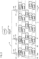
- Figure 3 illustrates many vehicles 50 travelling along a multi-lane roadway 52.
- the roadway 52 has five lanes moving in the direction of the arrow 54.
- a series of street light host 5G transceivers 32A, 32B ... and 32Z are located next to the road 52.
- the lighting enclosures 22A, 22B and 22Z would typically be mounted about 12 feet above the ground on lampposts 20A, 20B and 20Z.
- host 5G cell 32A is the nearest cell for vehicles 50A and 50AA
- host 5G cell 32B is the nearest cell for vehicle 50B
- Each host 5G cell 32A, 32B...32Z in the series has a physical coverage range and the coverage ranges overlap. Desirably, the overlapping ranges provide complete coverage for all the lanes on the roadway 52.
- FIG. 5 depicts an exemplary algorithm for streaming data from a series of lamppost 5G cells 32A, 32B, 32Z travelling with the vehicle 50 on the roadway 52.
- Block 60 illustrates a first step in which the vehicle's speed, direction of travel and the high speed data requirements are determined.
- the vehicle speed and direction of travel are most likely determined via triangulation of the signals from the host 5G cell transceivers 32A, 32B...32Z, although speed and direction can also be determined using radar or camera sensors, or even communicated from the vehicle 50 to the lamppost 5G cells 32.
- the next step shown in block 62, is for the 5G data consuming device to negotiate with the nearest host 5G cell 32A, 32B... 32A. It is possible for the initial negotiation to occur via the established 5G cellular connection or through 802.11p using a nearby or in luminaire access point or through a mesh of vehicles connected to the traffic infrastructure.
- the next step is for the router 58 or caching service on the internet 56 to calculate the relay buffers.
- This step is illustrated in block 64 in Figure 5 .
- the relay buffers are calculated to determine the necessary amount of data that needs to be queued up at the series of host 5G cells 32 down the roadway for calculated time intervals which are determined to coincide with the time interval that the respective vehicle 50 is within coverage range of the respective 5G cell 32.
- block 66 indicates that data is streamed from the relay buffers as the vehicle 50 passes the respective lamppost during the calculated time intervals.
- the process in Figure 5 repeats as indicated by arrow 68.
- the process as described requires a negotiation or renegotiation of credentials only between the nearest lamppost 5G cell in the series, and then the router 58 streams data via relay buffers delivered to the series of lamppost 5G cells 32B...32Z downstream of the nearest 5G cell 32A.
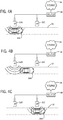
- FIGs 4A-4C these drawings illustrate vehicle 50A, initially shown in Figure 3 , as it is travelling along the road 52.
- Figure 3 depicts the 5G data consuming device(s) in vehicle 5A negotiating credentials with the nearest host 5G cell 32A.
- the vehicle 50A has moved down the roadway 52 and is now within range of the next 5G cell 32B in the series. Data is streamed from the relay buffer sent to the host 5G cell 32B by router 58 without having to renegotiate credentials.
- Figure 4B shows the vehicle 50A travelling along the road between host 5G cells 32B and 32C.
- 5G cells serve as the host transceivers for the purpose of this example, other transmission methods could also be used including various high speed RF protocol transceivers or transceivers using high speed Visual Light Communication (VLC) like Li-Fi.
- VLC Visual Light Communication
- the distance between light poles is a constant 100 feet, the vehicle will pass 52 light poles in a minute travelling at 60 mph.
- the 125MB of data is segmented into 2.4MB relay buffers and distributed to the next 52 lampposts with a broadcasting interval of TX x 1.15 seconds.
- the primary benefit being that the system allows continuous uninterrupted unicast of data transfer of large amounts of data without the overhead of roaming or switching between cell towers.
Landscapes
- Physics & Mathematics (AREA)
- General Physics & Mathematics (AREA)
- Engineering & Computer Science (AREA)
- Computer Networks & Wireless Communication (AREA)
- Signal Processing (AREA)
- Circuit Arrangement For Electric Light Sources In General (AREA)
- Traffic Control Systems (AREA)
- Mobile Radio Communication Systems (AREA)
Claims (15)
- Verfahren zum Bereitstellen einer drahtlosen Datenübertragung mit hoher Datengeschwindigkeit und hoher Bandbreite für Fahrzeuge (50, 50A, 50AA, 50B), die sich auf einer Straße (52) bewegen, das Verfahren umfassend die Schritte:a) Bereitstellen einer Vielzahl von Kommunikationsmodulen (28), Hochgeschwindigkeitsbussen zwischen Leuchten (34) und Hostzellen (32, 32A, 32B, 32Z);b) Bereitstellen eines drahtgebundenen Hochgeschwindigkeitskommunikationsmediums (36), das mit dem Internet (56) mit einer Vielzahl von Beleuchtungsgehäusen (22, 22A, 22B, 22Z) verbunden ist, die auf Lampenmasten (20, 20A, 20B, 20Z) montiert sind, die sich entlang der Straße (52) befinden;c) Platzieren mindestens eines Kommunikationsmoduls (28), eines Hochgeschwindigkeitsbusses zwischen Leuchten (34) und einer Hostzelle (32, 32A, 32 B, 32Z) in einem jeweiligen Beleuchtungsgehäuse (22, 22A, 22B, 22Z), das an den Lampenmasten (20, 20A, 20B, 20Z) montiert ist, die sich entlang der Straße (52) befinden, wobei jedes Kommunikationsmodul (28) mit einem drahtgebundenen Hochgeschwindigkeitskommunikationsmedium (36) und mit einem Hochgeschwindigkeitsbus zwischen Leuchten (34) verbunden ist und die jeweilige Hostzelle (32, 32A, 32B, 32Z) auch mit dem Hochgeschwindigkeitsbus zwischen Leuchten (34) verbunden ist; und wobei ferner jede Hostzelle (32, 32A, 32B, 32Z) eine Reichweite aufweist, die einen Abschnitt der Straße (52) nahe dem Lampenmast (20, 20A, 20B, 20Z), auf dem sie montiert ist, abdeckt und in der Lage ist, drahtlos Daten an datenverbrauchende Vorrichtungen zu übertragen, die mit Fahrzeugen (50, 50A, 50AA, 50B) auf der Straße (52) innerhalb der Reichweite der Hostzelle (32, 32A, 32B, 32Z) mitfahren und drahtlos Daten von datenverbrauchenden Vorrichtungen zu empfangen, die mit Fahrzeugen (50, 50A, 50AA, 50B) auf der Straße (52) innerhalb der Reichweite der Hostzelle (32, 32A, 32B, 32Z) mitfahren;d) während ein Fahrzeug (50, 50A, 50AA, 50B) auf der Straße (52) fährt, Bestimmen (60) der Geschwindigkeit des Fahrzeugs, der Fahrtrichtung und der Anforderungen an den Hochgeschwindigkeitsdatenstrom für eine ausgewählte Zeitspanne für datenverbrauchende Vorrichtungen, die in dem Fahrzeug (50, 50A, 50AA, 50B) mitfahren;e) Verhandeln (62) zwischen den datenverbrauchenden Vorrichtungen, die in dem Fahrzeug (50, 50A, 50AA, 50B) mitfahren, und der nächsten der Hostzellen (32, 32A, 32B, 32Z), während das Fahrzeug (50, 50A, 50AA, 50B) auf der Straße (52) fährt;f) Berechnen (64) eines Relaispuffers, der zu einer Reihe von Hostzellen (32, 32A, 32B, 32Z) in die Warteschlange eingereiht werden muss, die sich in Fahrtrichtung des Fahrzeugs (50, 50A, 50AA, 50B) erstrecken, für einen ununterbrochenen Dienst für die datenverbrauchenden Vorrichtungen, die in dem Fahrzeug (50, 50A, 50AA, 50B) mitfahren;g) Übertragen (66) einer jeweiligen Menge berechneter Relaispuffer von den jeweiligen Hostzellen (32, 32A, 32B, 32Z) während bestimmter Zeitintervalle ohne Neuverhandlung zwischen den datenverbrauchenden Vorrichtungen und den jeweiligen Hostzellen (32, 32A, 32B, 32Z), um eine ununterbrochene Übertragung von Daten an datenverbrauchende Vorrichtungen bereitzustellen, die in dem Fahrzeug (50, 50A, 50AA, 50B) mitfahren, während das Fahrzeug (50, 50A, 50AA, 50B) auf der Straße (52) fährt; undh) Wiederholen (68) der Schritte d) bis g), während das Fahrzeug (50, 50A, 50AA, 50B) weiter die Straße entlangfährt.
- Verfahren zum Bereitstellen einer drahtlosen Datenübertragung mit hoher Datengeschwindigkeit und hoher Bandbreite für Fahrzeuge (50, 50A, 50AA, 50B), die auf einer Straße (52) fahren, nach Anspruch 1, wobei der Schritt zum Berechnen von Relaispuffern, die zu einer Reihe von Hostzellen (32, 32A, 32B, 32Z) in die Warteschlange eingereiht werden müssen, die sich in Fahrtrichtung des Fahrzeugs (50, 50A, 50AA, 50B) erstrecken, für einen ununterbrochenen Dienst für die datenverbrauchenden Vorrichtungen, die in dem Fahrzeug (50, 50A, 50AA, 50B) mitfahren, durchgeführt wird durch:
Bestimmen der Anzahl zusätzlicher Lampenmasten (20, 20A, 20B, 20Z), die das Fahrzeug (50, 50A, 50AA, 50B) mit der für das Fahrzeug (50, 50A, 50AA, 50B) bestimmten Geschwindigkeit und Richtung während der ausgewählten Zeitspanne passieren wird, Bestimmen von Zeitintervallen, in denen das Fahrzeug (50, 50A, 50AA, 50B) die jeweiligen Lampenmasten (20, 20A, 20B, 20Z) passieren wird, und Berechnen einer Datenmenge, die in den jeweiligen Relaispuffern benötigt wird, um von der Hostzelle (32, 32A, 32B, 32Z) an den jeweiligen Lampenmasten (20, 20A, 20B, 20Z) in den bestimmten Zeitintervallen zu strömen. - Verfahren zum Bereitstellen einer drahtlosen Datenübertragung mit hoher Datengeschwindigkeit und hoher Bandbreite für Fahrzeuge (50, 50A, 50AA, 50B), die sich auf einer Straße (52) bewegen, nach Anspruch 1, wobei der Relaispuffer durch einen Router berechnet wird.
- Verfahren zum Bereitstellen einer drahtlosen Datenübertragung mit hoher Datengeschwindigkeit und hoher Bandbreite für Fahrzeuge (50, 50A, 50AA, 50B), die sich auf einer Straße (52) bewegen, nach Anspruch 1, wobei der Relaispuffer durch einen Cache-Dienst berechnet wird.
- Verfahren zum Bereitstellen einer drahtlosen Datenübertragung mit hoher Datengeschwindigkeit und hoher Bandbreite für Fahrzeuge (50, 50A, 50AA, 50B), die sich auf einer Straße (52) bewegen, nach Anspruch 1, ferner umfassend die Schritte: Bereitstellen eines Fahrzeug-Sender-Empfängers und einer Infrastruktur, die eine WiFi-Netzwerk- und/oder Bluetooth-Konnektivität zu datenverbrauchenden Vorrichtungen in dem Fahrzeug (50, 50A, 50AA, 50B) bereitstellt; und Übertragen eines Signals von dem Fahrzeug-Sender-Empfänger an die nächste Hostzelle (32, 32A, 32B, 32Z), das die Geschwindigkeit, Fahrtrichtung und Anforderungen an den Hochgeschwindigkeitsdatenstrom des Fahrzeugs (50, 50A, 50AA, 50B) für die ausgewählte Zeitspanne darstellt.
- Verfahren zum Bereitstellen einer drahtlosen Datenübertragung mit hoher Datengeschwindigkeit und hoher Bandbreite für Fahrzeuge (50, 50A, 50AA, 50B), die sich auf einer Straße (52) bewegen, nach Anspruch 1, wobei das drahtgebundene Hochgeschwindigkeitskommunikationsmedium (36), das mit dem Internet (56) mit einer Vielzahl von Beleuchtungsgehäusen (22, 22A, 22B, 22Z) verbunden ist, die auf Lampenmasten (20, 20A, 20B, 20Z) montiert sind, die sich entlang der Straße (52) befinden, ein faseroptisches Medium ist und jedes jeweilige Kommunikationsmodul (28) einen Anschluss zum Verbinden mit dem faseroptischen Medium umfasst.
- Verfahren zum Bereitstellen einer drahtlosen Datenübertragung mit hoher Datengeschwindigkeit und hoher Bandbreite für Fahrzeuge (50, 50A, 50AA, 50B), die sich auf einer Straße (52) bewegen, nach Anspruch 1, wobei mindestens einige der Hostzellen (32, 32A, 32B, 32Z) Mikrozellen sind oder wobei mindestens einige der Hostzellen (32, 32A, 32B, 32Z) Femtozellen sind.
- Verfahren zum Bereitstellen einer drahtlosen Datenübertragung mit hoher Datengeschwindigkeit und hoher Bandbreite für Fahrzeuge (50, 50A, 50AA, 50B), die sich auf einer Straße (52) bewegen, nach Anspruch 1, wobei das Bestimmen der Geschwindigkeit und Fahrtrichtung des Fahrzeugs durch Triangulieren von Signalen von einer oder mehreren datenverbrauchenden Vorrichtungen, die in dem Fahrzeug (50, 50A, 50AA, 50B) mitfahren, durchgeführt wird.
- Verfahren zum Bereitstellen einer drahtlosen Datenübertragung mit hoher Datengeschwindigkeit und hoher Bandbreite für Fahrzeuge (50, 50A, 50AA, 50B), die sich auf einer Straße (52) bewegen, nach Anspruch 1, wobei der Schritt e) des Verhandelns zwischen datenverbrauchenden Vorrichtungen, die in dem Fahrzeug (50, 50A, 50AA, 50B) mitfahren, und der nächsten der Hostzellen (32, 32A, 32B, 32Z), während das Fahrzeug (50, 50A, 50AA, 50B) auf der Straße (52) fährt, wiederholt in festen Zeitintervallen durchgeführt wird.
- Verfahren zum Bereitstellen einer drahtlosen Datenübertragung mit hoher Datengeschwindigkeit und hoher Bandbreite für Fahrzeuge (50, 50A, 50AA, 50B), die sich auf einer Straße (52) bewegen, nach Anspruch 1, wobei der Schritt e) des Verhandelns zwischen datenverbrauchenden Vorrichtungen, die in dem Fahrzeug (50, 50A, 50AA, 50B) mitfahren, und der nächsten der Hostzellen (32, 32A, 32B, 32Z), während das Fahrzeug (50, 50A, 50AA, 50B) auf der Straße (52) fährt, wiederholt nach einer berechneten Anzahl von Lampenmasten (20, 20A, 20B, 20Z) durchgeführt wird.
- Verfahren zum Bereitstellen einer drahtlosen Datenübertragung mit hoher Datengeschwindigkeit und hoher Bandbreite für Fahrzeuge (50, 50A, 50AA, 50B), die sich auf einer Straße (52) bewegen, nach Anspruch 1, wobei der Schritt e) des Verhandelns zwischen datenverbrauchenden Vorrichtungen, die in dem Fahrzeug (50, 50A, 50AA, 50B) mitfahren, und der nächsten der Hostzellen (32, 32A, 32B, 32Z), während das Fahrzeug (50, 50A, 50AA, 50B) auf der Straße (52) fährt, ebenso wie Schritt f) ferner implementiert werden, wenn eine unerwartete Unterbrechung des Diensts auftritt.
- Verfahren zum Bereitstellen einer drahtlosen Datenübertragung mit hoher Datengeschwindigkeit und hoher Bandbreite für Fahrzeuge (50, 50A, 50AA, 50B), die sich auf einer Straße (52) bewegen, nach Anspruch 1, wobei ein LED-Modul (24) und ein LED-Treiber (26) in jedem der jeweiligen Beleuchtungsgehäuse (22, 22A, 22B, 22Z), die an den Lampenmasten (20, 20A, 20B, 20Z) montiert sind, die sich entlang der Straße (52) befinden, platziert ist, und das Kommunikationsmodul (28) in dem jeweiligen Beleuchtungsgehäuse (22, 22A, 22B, 22Z) mit dem LED-Treiber (26) über den jeweiligen Hochgeschwindigkeitsbus zwischen Leuchten (34) verbunden ist.
- Verfahren zum Bereitstellen einer drahtlosen Datenübertragung mit hoher Datengeschwindigkeit und hoher Bandbreite für Fahrzeuge (50, 50A, 50AA, 50B), die sich auf einer Straße (52) bewegen, nach Anspruch 12, wobei das Kommunikationsmodul (28) ferner Netzstrom empfängt, oder
wobei Strom und Internetkonnektivität mindestens einem der Kommunikationsmodule (28) über ein Power-over-Ethernet-Kabel bereitgestellt werden, das von einer PoE-Schaltung mit Strom versorgt wird. - Verfahren zum Bereitstellen einer drahtlosen Datenübertragung mit hoher Datengeschwindigkeit und hoher Bandbreite für Fahrzeuge (50, 50A, 50AA, 50B), die sich auf einer Straße (52) bewegen, nach Anspruch 12, wobei ein Umgebungssensor (30) in mindestens einem der Beleuchtungsgehäuse (22, 22A, 22B, 22Z), die an den Lampenmasten (20, 20A, 20B, 20Z) montiert sind, die sich entlang der Straße (52) befinden, platziert ist und der Sensor (30) mit dem Kommunikationsmodul (28) in dem jeweiligen Beleuchtungsgehäuse (22, 22A, 22B, 22Z) über den jeweiligen Hochgeschwindigkeitsbus zwischen Leuchten (34) verbunden ist.
- Verfahren zum Bereitstellen einer drahtlosen Datenübertragung mit hoher Datengeschwindigkeit und hoher Bandbreite für Fahrzeuge (50, 50A, 50AA, 50B), die sich auf einer Straße (52) bewegen, das Verfahren umfassend die Schritte:
Bereitstellen einer Vielzahl von Kommunikationsmodulen (28), Hochgeschwindigkeitsbussen zwischen Leuchten (34) und Host-Sender-Empfängern (32, 32A, 32B, 32Z), wobei jeder Host-Sender-Empfänger (32, 32A, 32B, 32Z) entweder eine Zelle, eine Vorrichtung, die ein Hochgeschwindigkeits-HF-Kommunikationsprotokoll verwendet, oder eine Vorrichtung, die ein Hochgeschwindigkeits-Visual-Light-Kommunikationsprotokoll (VLC-Protokoll) verwendet, ist;a) Bereitstellen eines drahtgebundenen Hochgeschwindigkeitskommunikationsmediums (36), das mit dem Internet (56) mit einer Vielzahl von Beleuchtungsgehäusen (22, 22A, 22B, 22Z) verbunden ist, die auf Lampenmasten (20, 20A, 20B, 20Z) montiert sind, die sich entlang der Straße (52) befinden;b) Platzieren mindestens eines Kommunikationsmoduls (28), eines Hochgeschwindigkeitsbusses zwischen Leuchten (34) und eines Host-Empfänger-Senders (32, 32A, 32 B, 32Z) in einem jeweiligen Beleuchtungsgehäuse (22, 22A, 22B, 22Z), das an den Lampenmasten (20, 20A, 20B, 20Z) montiert ist, die sich entlang der Straße (52) befinden, wobei jedes Kommunikationsmodul (28) mit einem drahtgebundenen Hochgeschwindigkeitskommunikationsmedium (36) und mit einem Hochgeschwindigkeitsbus zwischen Leuchten (34) verbunden ist und der jeweilige Host-Sender-Empfänger (32, 32A, 32B, 32Z) auch mit dem Hochgeschwindigkeitsbus zwischen Leuchten (34) verbunden ist; und wobei ferner jeder Host-Sender-Empfänger (32, 32A, 32B, 32Z) eine Reichweite aufweist, die einen Abschnitt der Straße (52) nahe dem Lampenmast (20, 20A, 20B, 20Z), auf dem sie montiert ist, abdeckt und in der Lage ist, drahtlos Daten an datenverbrauchende Vorrichtungen zu übertragen, die mit Fahrzeugen (50, 50A, 50AA, 50B) auf der Straße (52) innerhalb der Reichweite des Host-Sender-Empfängers (32, 32A, 32B, 32Z) mitfahren und drahtlos Daten von datenverbrauchenden Vorrichtungen zu empfangen, die mit Fahrzeugen (50, 50A, 50AA, 50B) auf der Straße (52) innerhalb der Reichweite des Host-Sender-Empfängers (32, 32A, 32B, 32Z) mitfahren;c) während ein Fahrzeug (50, 50A, 50AA, 50B) auf der Straße (52) fährt, Bestimmen der Geschwindigkeit des Fahrzeugs, der Fahrtrichtung und der Anforderungen an den Hochgeschwindigkeitsdatenstrom für eine ausgewählte Zeitspanne für datenverbrauchende Vorrichtungen, die in dem Fahrzeug (50, 50A, 50AA, 50B) mitfahren;d) Verhandeln zwischen den datenverbrauchenden Vorrichtungen, die in dem Fahrzeug (50, 50A, 50AA, 50B) mitfahren, und dem nächsten der Host-Sender-Empfänger (32, 32A, 32B, 32Z), während das Fahrzeug (50, 50A, 50AA, 50B) auf der Straße (52) fährt;e) Berechnen eines Relaispuffers, der zu einer Reihe von Host-Sender-Empfängern (32, 32A, 32B, 32Z) in die Warteschlange eingereiht werden muss, die sich in Fahrtrichtung des Fahrzeugs (50, 50A, 50AA, 50B) erstrecken, für einen ununterbrochenen Dienst für die datenverbrauchenden Vorrichtungen, die in dem Fahrzeug (50, 50A, 50AA, 50B) mitfahren;f) Übertragen einer jeweiligen Menge berechneter Relaispuffer von den jeweiligen Host-Sender-Empfängern (32, 32A, 32B, 32Z) während bestimmter Zeitintervalle ohne Neuverhandlung zwischen den datenverbrauchenden Vorrichtungen und den jeweiligen Host-Sender-Empfängern (32, 32A, 32B, 32Z), um eine ununterbrochene Übertragung von Daten an datenverbrauchende Vorrichtungen bereitzustellen, die in dem Fahrzeug (50, 50A, 50AA, 50B) mitfahren, während das Fahrzeug (50, 50A, 50AA, 50B) auf der Straße (52) fährt; undg) Wiederholen der Schritte c) bis f), während das Fahrzeug (50, 50A, 50AA, 50B) weiter die Straße entlangfährt.
Applications Claiming Priority (2)
| Application Number | Priority Date | Filing Date | Title |
|---|---|---|---|
| US201662432197P | 2016-12-09 | 2016-12-09 | |
| PCT/IB2017/057767 WO2018104924A1 (en) | 2016-12-09 | 2017-12-10 | Network infrastructure and switching through streetlights |
Publications (3)
| Publication Number | Publication Date |
|---|---|
| EP3533249A1 EP3533249A1 (de) | 2019-09-04 |
| EP3533249B1 true EP3533249B1 (de) | 2021-03-17 |
| EP3533249B8 EP3533249B8 (de) | 2021-09-08 |
Family
ID=60943057
Family Applications (1)
| Application Number | Title | Priority Date | Filing Date |
|---|---|---|---|
| EP17826288.7A Active EP3533249B8 (de) | 2016-12-09 | 2017-12-10 | Netzwerkinfrastruktur und schaltung durch strassenlichter |
Country Status (3)
| Country | Link |
|---|---|
| EP (1) | EP3533249B8 (de) |
| CN (1) | CN110050476B (de) |
| WO (1) | WO2018104924A1 (de) |
Families Citing this family (2)
| Publication number | Priority date | Publication date | Assignee | Title |
|---|---|---|---|---|
| DE102020124557A1 (de) | 2020-09-21 | 2022-03-24 | Siteco Gmbh | Straßenleuchte mit Edge-Computing-Einrichtung |
| DE102020124560A1 (de) | 2020-09-21 | 2022-03-24 | Siteco Gmbh | Straßenleuchte mit Mobilfunkbasisstation |
Citations (2)
| Publication number | Priority date | Publication date | Assignee | Title |
|---|---|---|---|---|
| US20100070167A1 (en) * | 2008-09-12 | 2010-03-18 | Gm Global Technology Operations, Inc. | System and method for data communication between a vehicle and an infrastructure |
| CN204392313U (zh) * | 2015-03-11 | 2015-06-10 | 李铁军 | 车辆专用无线数据通信系统 |
Family Cites Families (6)
| Publication number | Priority date | Publication date | Assignee | Title |
|---|---|---|---|---|
| KR100404392B1 (ko) * | 2001-06-28 | 2003-11-03 | 엘지전자 주식회사 | 지능형 교통망 시스템의 대용량 데이터 전송방법 |
| US7813843B2 (en) * | 2007-01-04 | 2010-10-12 | Cisco Technology, Inc | Ad-hoc mobile IP network for intelligent transportation system |
| CN102595651A (zh) * | 2011-01-18 | 2012-07-18 | 张东 | 一种可工作于五吉赫以上频谱的蜂窝无线网络 |
| CN103167569B (zh) * | 2013-03-01 | 2016-06-08 | 北京邮电大学 | 一种基于接力切换的td-lte通信系统的快速切换方法 |
| CN103475409B (zh) * | 2013-09-05 | 2016-05-25 | 江苏大学 | 移动车辆可见光无线通信接收切换方法和装置 |
| CN105554120A (zh) * | 2015-12-18 | 2016-05-04 | 宇龙计算机通信科技(深圳)有限公司 | 用于车辆通信的数据传输方法及数据传输装置、路侧单元 |
-
2017
- 2017-12-10 CN CN201780075709.XA patent/CN110050476B/zh active Active
- 2017-12-10 EP EP17826288.7A patent/EP3533249B8/de active Active
- 2017-12-10 WO PCT/IB2017/057767 patent/WO2018104924A1/en not_active Ceased
Patent Citations (2)
| Publication number | Priority date | Publication date | Assignee | Title |
|---|---|---|---|---|
| US20100070167A1 (en) * | 2008-09-12 | 2010-03-18 | Gm Global Technology Operations, Inc. | System and method for data communication between a vehicle and an infrastructure |
| CN204392313U (zh) * | 2015-03-11 | 2015-06-10 | 李铁军 | 车辆专用无线数据通信系统 |
Also Published As
| Publication number | Publication date |
|---|---|
| CN110050476B (zh) | 2023-06-06 |
| WO2018104924A1 (en) | 2018-06-14 |
| CN110050476A (zh) | 2019-07-23 |
| EP3533249A1 (de) | 2019-09-04 |
| EP3533249B8 (de) | 2021-09-08 |
Similar Documents
| Publication | Publication Date | Title |
|---|---|---|
| CN104300646B (zh) | 一种支持车联网的多频段智能充电桩系统 | |
| CN106373398B (zh) | 基于蓝牙通信的交通传感器组网方法 | |
| CN110383101A (zh) | Hd地图的生成和使用 | |
| JP7347748B2 (ja) | 磁気誘導通信ベースの車両制御装置および方法 | |
| KR102914997B1 (ko) | 사이드링크를 지원하는 무선통신시스템에서 vru가 이동 경로를 예측하는 방법 및 이를 위한 장치 | |
| CN107507444A (zh) | 用于无人驾驶的智能公路系统及其控制方法 | |
| CN110291569A (zh) | 一种用于停车管理及控制的相关的视频和照明系统 | |
| CN110213716A (zh) | 一种基于雾无线接入网络的车联组网方法 | |
| CN109450536B (zh) | 一种基于可见光通信的车辆物联网系统及通信方法 | |
| EP3533249B1 (de) | Netzwerkinfrastruktur und schaltung durch strassenlichter | |
| CN105844925B (zh) | 基于手机无线网的城市交通控制装置、系统及方法 | |
| KR20210000491A (ko) | 스마트 가로등 및 이를 포함하는 스마트 가로등 시스템 | |
| CN206147948U (zh) | 一种城市交通控制系统 | |
| CN103117000B (zh) | 一种路况监测装置 | |
| CN120475348A (zh) | 一种面向网联协同驾驶的混合式网络通信系统 | |
| CN104504932A (zh) | 一种结合公交平台的车载自组网停车位发布系统 | |
| KR20220153030A (ko) | 사이드링크를 지원하는 무선통신시스템에서 vru 장치가 진입 경로를 예측하는 방법 및 이를 위한 장치 | |
| GB2560706A (en) | Network infrastructure and switching through streetlights | |
| JP2010170241A (ja) | 通信制御装置とこれを備えた路側通信機 | |
| US11038638B2 (en) | Dual connectivity support for V2X communication | |
| CN119521165A (zh) | 面向协作式换道的c-v2x集中式通信方法 | |
| JP5773030B2 (ja) | 通信制御装置、路側通信機、移動通信機、及び、通信システム | |
| CN104680801A (zh) | Suats物联网智能交通控制系统 | |
| JP2011114647A (ja) | 通信制御装置、路側通信機、移動通信機、及び、通信システム | |
| CN107123278A (zh) | 一种双无线通道交互式红绿灯控制基站 |
Legal Events
| Date | Code | Title | Description |
|---|---|---|---|
| STAA | Information on the status of an ep patent application or granted ep patent |
Free format text: STATUS: UNKNOWN |
|
| STAA | Information on the status of an ep patent application or granted ep patent |
Free format text: STATUS: THE INTERNATIONAL PUBLICATION HAS BEEN MADE |
|
| PUAI | Public reference made under article 153(3) epc to a published international application that has entered the european phase |
Free format text: ORIGINAL CODE: 0009012 |
|
| STAA | Information on the status of an ep patent application or granted ep patent |
Free format text: STATUS: REQUEST FOR EXAMINATION WAS MADE |
|
| 17P | Request for examination filed |
Effective date: 20190527 |
|
| AK | Designated contracting states |
Kind code of ref document: A1 Designated state(s): AL AT BE BG CH CY CZ DE DK EE ES FI FR GB GR HR HU IE IS IT LI LT LU LV MC MK MT NL NO PL PT RO RS SE SI SK SM TR |
|
| AX | Request for extension of the european patent |
Extension state: BA ME |
|
| DAV | Request for validation of the european patent (deleted) | ||
| DAX | Request for extension of the european patent (deleted) | ||
| GRAP | Despatch of communication of intention to grant a patent |
Free format text: ORIGINAL CODE: EPIDOSNIGR1 |
|
| STAA | Information on the status of an ep patent application or granted ep patent |
Free format text: STATUS: GRANT OF PATENT IS INTENDED |
|
| RIC1 | Information provided on ipc code assigned before grant |
Ipc: G08G 1/052 20060101ALI20201116BHEP Ipc: G08G 1/095 20060101ALI20201116BHEP Ipc: H04W 28/08 20090101ALN20201116BHEP Ipc: F21S 8/08 20060101ALN20201116BHEP Ipc: H04W 16/04 20090101AFI20201116BHEP Ipc: F21V 23/04 20060101ALN20201116BHEP |
|
| INTG | Intention to grant announced |
Effective date: 20201130 |
|
| GRAS | Grant fee paid |
Free format text: ORIGINAL CODE: EPIDOSNIGR3 |
|
| GRAA | (expected) grant |
Free format text: ORIGINAL CODE: 0009210 |
|
| STAA | Information on the status of an ep patent application or granted ep patent |
Free format text: STATUS: THE PATENT HAS BEEN GRANTED |
|
| AK | Designated contracting states |
Kind code of ref document: B1 Designated state(s): AL AT BE BG CH CY CZ DE DK EE ES FI FR GB GR HR HU IE IS IT LI LT LU LV MC MK MT NL NO PL PT RO RS SE SI SK SM TR |
|
| REG | Reference to a national code |
Ref country code: GB Ref legal event code: FG4D |
|
| REG | Reference to a national code |
Ref country code: CH Ref legal event code: EP |
|
| REG | Reference to a national code |
Ref country code: DE Ref legal event code: R096 Ref document number: 602017034926 Country of ref document: DE |
|
| REG | Reference to a national code |
Ref country code: IE Ref legal event code: FG4D |
|
| REG | Reference to a national code |
Ref country code: AT Ref legal event code: REF Ref document number: 1373417 Country of ref document: AT Kind code of ref document: T Effective date: 20210415 |
|
| REG | Reference to a national code |
Ref country code: LT Ref legal event code: MG9D |
|
| PG25 | Lapsed in a contracting state [announced via postgrant information from national office to epo] |
Ref country code: NO Free format text: LAPSE BECAUSE OF FAILURE TO SUBMIT A TRANSLATION OF THE DESCRIPTION OR TO PAY THE FEE WITHIN THE PRESCRIBED TIME-LIMIT Effective date: 20210617 Ref country code: GR Free format text: LAPSE BECAUSE OF FAILURE TO SUBMIT A TRANSLATION OF THE DESCRIPTION OR TO PAY THE FEE WITHIN THE PRESCRIBED TIME-LIMIT Effective date: 20210618 Ref country code: HR Free format text: LAPSE BECAUSE OF FAILURE TO SUBMIT A TRANSLATION OF THE DESCRIPTION OR TO PAY THE FEE WITHIN THE PRESCRIBED TIME-LIMIT Effective date: 20210317 Ref country code: FI Free format text: LAPSE BECAUSE OF FAILURE TO SUBMIT A TRANSLATION OF THE DESCRIPTION OR TO PAY THE FEE WITHIN THE PRESCRIBED TIME-LIMIT Effective date: 20210317 Ref country code: BG Free format text: LAPSE BECAUSE OF FAILURE TO SUBMIT A TRANSLATION OF THE DESCRIPTION OR TO PAY THE FEE WITHIN THE PRESCRIBED TIME-LIMIT Effective date: 20210617 |
|
| GRAT | Correction requested after decision to grant or after decision to maintain patent in amended form |
Free format text: ORIGINAL CODE: EPIDOSNCDEC |
|
| REG | Reference to a national code |
Ref country code: CH Ref legal event code: PK Free format text: BERICHTIGUNG B8 |
|
| REG | Reference to a national code |
Ref country code: DE Ref legal event code: R081 Ref document number: 602017034926 Country of ref document: DE Owner name: TRIDONIC INC., HIGHLAND, US Free format text: FORMER OWNER: TRIDONIC INC., DORNBIRN, NY, US |
|
| REG | Reference to a national code |
Ref country code: NL Ref legal event code: MP Effective date: 20210317 |
|
| PG25 | Lapsed in a contracting state [announced via postgrant information from national office to epo] |
Ref country code: LV Free format text: LAPSE BECAUSE OF FAILURE TO SUBMIT A TRANSLATION OF THE DESCRIPTION OR TO PAY THE FEE WITHIN THE PRESCRIBED TIME-LIMIT Effective date: 20210317 Ref country code: RS Free format text: LAPSE BECAUSE OF FAILURE TO SUBMIT A TRANSLATION OF THE DESCRIPTION OR TO PAY THE FEE WITHIN THE PRESCRIBED TIME-LIMIT Effective date: 20210317 Ref country code: SE Free format text: LAPSE BECAUSE OF FAILURE TO SUBMIT A TRANSLATION OF THE DESCRIPTION OR TO PAY THE FEE WITHIN THE PRESCRIBED TIME-LIMIT Effective date: 20210317 |
|
| RAP4 | Party data changed (patent owner data changed or rights of a patent transferred) |
Owner name: TRIDONIC INC. |
|
| PG25 | Lapsed in a contracting state [announced via postgrant information from national office to epo] |
Ref country code: NL Free format text: LAPSE BECAUSE OF FAILURE TO SUBMIT A TRANSLATION OF THE DESCRIPTION OR TO PAY THE FEE WITHIN THE PRESCRIBED TIME-LIMIT Effective date: 20210317 |
|
| PG25 | Lapsed in a contracting state [announced via postgrant information from national office to epo] |
Ref country code: SM Free format text: LAPSE BECAUSE OF FAILURE TO SUBMIT A TRANSLATION OF THE DESCRIPTION OR TO PAY THE FEE WITHIN THE PRESCRIBED TIME-LIMIT Effective date: 20210317 Ref country code: LT Free format text: LAPSE BECAUSE OF FAILURE TO SUBMIT A TRANSLATION OF THE DESCRIPTION OR TO PAY THE FEE WITHIN THE PRESCRIBED TIME-LIMIT Effective date: 20210317 Ref country code: CZ Free format text: LAPSE BECAUSE OF FAILURE TO SUBMIT A TRANSLATION OF THE DESCRIPTION OR TO PAY THE FEE WITHIN THE PRESCRIBED TIME-LIMIT Effective date: 20210317 Ref country code: EE Free format text: LAPSE BECAUSE OF FAILURE TO SUBMIT A TRANSLATION OF THE DESCRIPTION OR TO PAY THE FEE WITHIN THE PRESCRIBED TIME-LIMIT Effective date: 20210317 |
|
| REG | Reference to a national code |
Ref country code: DE Ref legal event code: R084 Ref document number: 602017034926 Country of ref document: DE |
|
| PG25 | Lapsed in a contracting state [announced via postgrant information from national office to epo] |
Ref country code: PL Free format text: LAPSE BECAUSE OF FAILURE TO SUBMIT A TRANSLATION OF THE DESCRIPTION OR TO PAY THE FEE WITHIN THE PRESCRIBED TIME-LIMIT Effective date: 20210317 Ref country code: PT Free format text: LAPSE BECAUSE OF FAILURE TO SUBMIT A TRANSLATION OF THE DESCRIPTION OR TO PAY THE FEE WITHIN THE PRESCRIBED TIME-LIMIT Effective date: 20210719 Ref country code: SK Free format text: LAPSE BECAUSE OF FAILURE TO SUBMIT A TRANSLATION OF THE DESCRIPTION OR TO PAY THE FEE WITHIN THE PRESCRIBED TIME-LIMIT Effective date: 20210317 Ref country code: RO Free format text: LAPSE BECAUSE OF FAILURE TO SUBMIT A TRANSLATION OF THE DESCRIPTION OR TO PAY THE FEE WITHIN THE PRESCRIBED TIME-LIMIT Effective date: 20210317 Ref country code: IS Free format text: LAPSE BECAUSE OF FAILURE TO SUBMIT A TRANSLATION OF THE DESCRIPTION OR TO PAY THE FEE WITHIN THE PRESCRIBED TIME-LIMIT Effective date: 20210717 |
|
| REG | Reference to a national code |
Ref country code: DE Ref legal event code: R097 Ref document number: 602017034926 Country of ref document: DE |
|
| PLBE | No opposition filed within time limit |
Free format text: ORIGINAL CODE: 0009261 |
|
| STAA | Information on the status of an ep patent application or granted ep patent |
Free format text: STATUS: NO OPPOSITION FILED WITHIN TIME LIMIT |
|
| PG25 | Lapsed in a contracting state [announced via postgrant information from national office to epo] |
Ref country code: ES Free format text: LAPSE BECAUSE OF FAILURE TO SUBMIT A TRANSLATION OF THE DESCRIPTION OR TO PAY THE FEE WITHIN THE PRESCRIBED TIME-LIMIT Effective date: 20210317 Ref country code: DK Free format text: LAPSE BECAUSE OF FAILURE TO SUBMIT A TRANSLATION OF THE DESCRIPTION OR TO PAY THE FEE WITHIN THE PRESCRIBED TIME-LIMIT Effective date: 20210317 Ref country code: AL Free format text: LAPSE BECAUSE OF FAILURE TO SUBMIT A TRANSLATION OF THE DESCRIPTION OR TO PAY THE FEE WITHIN THE PRESCRIBED TIME-LIMIT Effective date: 20210317 |
|
| 26N | No opposition filed |
Effective date: 20211220 |
|
| PG25 | Lapsed in a contracting state [announced via postgrant information from national office to epo] |
Ref country code: SI Free format text: LAPSE BECAUSE OF FAILURE TO SUBMIT A TRANSLATION OF THE DESCRIPTION OR TO PAY THE FEE WITHIN THE PRESCRIBED TIME-LIMIT Effective date: 20210317 |
|
| PG25 | Lapsed in a contracting state [announced via postgrant information from national office to epo] |
Ref country code: IT Free format text: LAPSE BECAUSE OF FAILURE TO SUBMIT A TRANSLATION OF THE DESCRIPTION OR TO PAY THE FEE WITHIN THE PRESCRIBED TIME-LIMIT Effective date: 20210317 |
|
| PG25 | Lapsed in a contracting state [announced via postgrant information from national office to epo] |
Ref country code: IS Free format text: LAPSE BECAUSE OF FAILURE TO SUBMIT A TRANSLATION OF THE DESCRIPTION OR TO PAY THE FEE WITHIN THE PRESCRIBED TIME-LIMIT Effective date: 20210717 |
|
| PG25 | Lapsed in a contracting state [announced via postgrant information from national office to epo] |
Ref country code: MC Free format text: LAPSE BECAUSE OF FAILURE TO SUBMIT A TRANSLATION OF THE DESCRIPTION OR TO PAY THE FEE WITHIN THE PRESCRIBED TIME-LIMIT Effective date: 20210317 |
|
| REG | Reference to a national code |
Ref country code: CH Ref legal event code: PL |
|
| REG | Reference to a national code |
Ref country code: BE Ref legal event code: MM Effective date: 20211231 |
|
| PG25 | Lapsed in a contracting state [announced via postgrant information from national office to epo] |
Ref country code: LU Free format text: LAPSE BECAUSE OF NON-PAYMENT OF DUE FEES Effective date: 20211210 Ref country code: IE Free format text: LAPSE BECAUSE OF NON-PAYMENT OF DUE FEES Effective date: 20211210 |
|
| PG25 | Lapsed in a contracting state [announced via postgrant information from national office to epo] |
Ref country code: BE Free format text: LAPSE BECAUSE OF NON-PAYMENT OF DUE FEES Effective date: 20211231 |
|
| PG25 | Lapsed in a contracting state [announced via postgrant information from national office to epo] |
Ref country code: LI Free format text: LAPSE BECAUSE OF NON-PAYMENT OF DUE FEES Effective date: 20211231 Ref country code: CH Free format text: LAPSE BECAUSE OF NON-PAYMENT OF DUE FEES Effective date: 20211231 |
|
| PG25 | Lapsed in a contracting state [announced via postgrant information from national office to epo] |
Ref country code: CY Free format text: LAPSE BECAUSE OF FAILURE TO SUBMIT A TRANSLATION OF THE DESCRIPTION OR TO PAY THE FEE WITHIN THE PRESCRIBED TIME-LIMIT Effective date: 20210317 |
|
| P01 | Opt-out of the competence of the unified patent court (upc) registered |
Effective date: 20230530 |
|
| PG25 | Lapsed in a contracting state [announced via postgrant information from national office to epo] |
Ref country code: HU Free format text: LAPSE BECAUSE OF FAILURE TO SUBMIT A TRANSLATION OF THE DESCRIPTION OR TO PAY THE FEE WITHIN THE PRESCRIBED TIME-LIMIT; INVALID AB INITIO Effective date: 20171210 |
|
| REG | Reference to a national code |
Ref country code: AT Ref legal event code: MM01 Ref document number: 1373417 Country of ref document: AT Kind code of ref document: T Effective date: 20221210 |
|
| PG25 | Lapsed in a contracting state [announced via postgrant information from national office to epo] |
Ref country code: AT Free format text: LAPSE BECAUSE OF NON-PAYMENT OF DUE FEES Effective date: 20221210 |
|
| PG25 | Lapsed in a contracting state [announced via postgrant information from national office to epo] |
Ref country code: MK Free format text: LAPSE BECAUSE OF FAILURE TO SUBMIT A TRANSLATION OF THE DESCRIPTION OR TO PAY THE FEE WITHIN THE PRESCRIBED TIME-LIMIT Effective date: 20210317 Ref country code: AT Free format text: LAPSE BECAUSE OF NON-PAYMENT OF DUE FEES Effective date: 20221210 |
|
| PG25 | Lapsed in a contracting state [announced via postgrant information from national office to epo] |
Ref country code: TR Free format text: LAPSE BECAUSE OF FAILURE TO SUBMIT A TRANSLATION OF THE DESCRIPTION OR TO PAY THE FEE WITHIN THE PRESCRIBED TIME-LIMIT Effective date: 20210317 |
|
| PG25 | Lapsed in a contracting state [announced via postgrant information from national office to epo] |
Ref country code: MT Free format text: LAPSE BECAUSE OF FAILURE TO SUBMIT A TRANSLATION OF THE DESCRIPTION OR TO PAY THE FEE WITHIN THE PRESCRIBED TIME-LIMIT Effective date: 20210317 |
|
| PGFP | Annual fee paid to national office [announced via postgrant information from national office to epo] |
Ref country code: FR Payment date: 20241227 Year of fee payment: 8 |
|
| PGFP | Annual fee paid to national office [announced via postgrant information from national office to epo] |
Ref country code: DE Payment date: 20241227 Year of fee payment: 8 |
|
| REG | Reference to a national code |
Ref country code: AT Ref legal event code: UEP Ref document number: 1373417 Country of ref document: AT Kind code of ref document: T Effective date: 20210317 |
|
| PGFP | Annual fee paid to national office [announced via postgrant information from national office to epo] |
Ref country code: GB Payment date: 20251223 Year of fee payment: 9 |