EP3532776B1 - Filter system for filtering a flow, extractor hood comprising such filter, and method for filtering air - Google Patents
Filter system for filtering a flow, extractor hood comprising such filter, and method for filtering air Download PDFInfo
- Publication number
- EP3532776B1 EP3532776B1 EP16798294.1A EP16798294A EP3532776B1 EP 3532776 B1 EP3532776 B1 EP 3532776B1 EP 16798294 A EP16798294 A EP 16798294A EP 3532776 B1 EP3532776 B1 EP 3532776B1
- Authority
- EP
- European Patent Office
- Prior art keywords
- filter
- filter system
- air
- housing
- foregoing
- Prior art date
- Legal status (The legal status is an assumption and is not a legal conclusion. Google has not performed a legal analysis and makes no representation as to the accuracy of the status listed.)
- Active
Links
Images


Classifications
-
- F—MECHANICAL ENGINEERING; LIGHTING; HEATING; WEAPONS; BLASTING
- F24—HEATING; RANGES; VENTILATING
- F24C—DOMESTIC STOVES OR RANGES ; DETAILS OF DOMESTIC STOVES OR RANGES, OF GENERAL APPLICATION
- F24C15/00—Details
- F24C15/20—Removing cooking fumes
- F24C15/2035—Arrangement or mounting of filters
-
- B—PERFORMING OPERATIONS; TRANSPORTING
- B03—SEPARATION OF SOLID MATERIALS USING LIQUIDS OR USING PNEUMATIC TABLES OR JIGS; MAGNETIC OR ELECTROSTATIC SEPARATION OF SOLID MATERIALS FROM SOLID MATERIALS OR FLUIDS; SEPARATION BY HIGH-VOLTAGE ELECTRIC FIELDS
- B03C—MAGNETIC OR ELECTROSTATIC SEPARATION OF SOLID MATERIALS FROM SOLID MATERIALS OR FLUIDS; SEPARATION BY HIGH-VOLTAGE ELECTRIC FIELDS
- B03C3/00—Separating dispersed particles from gases or vapour, e.g. air, by electrostatic effect
- B03C3/017—Combinations of electrostatic separation with other processes, not otherwise provided for
-
- B—PERFORMING OPERATIONS; TRANSPORTING
- B03—SEPARATION OF SOLID MATERIALS USING LIQUIDS OR USING PNEUMATIC TABLES OR JIGS; MAGNETIC OR ELECTROSTATIC SEPARATION OF SOLID MATERIALS FROM SOLID MATERIALS OR FLUIDS; SEPARATION BY HIGH-VOLTAGE ELECTRIC FIELDS
- B03C—MAGNETIC OR ELECTROSTATIC SEPARATION OF SOLID MATERIALS FROM SOLID MATERIALS OR FLUIDS; SEPARATION BY HIGH-VOLTAGE ELECTRIC FIELDS
- B03C3/00—Separating dispersed particles from gases or vapour, e.g. air, by electrostatic effect
- B03C3/02—Plant or installations having external electricity supply
- B03C3/04—Plant or installations having external electricity supply dry type
- B03C3/06—Plant or installations having external electricity supply dry type characterised by presence of stationary tube electrodes
-
- B—PERFORMING OPERATIONS; TRANSPORTING
- B03—SEPARATION OF SOLID MATERIALS USING LIQUIDS OR USING PNEUMATIC TABLES OR JIGS; MAGNETIC OR ELECTROSTATIC SEPARATION OF SOLID MATERIALS FROM SOLID MATERIALS OR FLUIDS; SEPARATION BY HIGH-VOLTAGE ELECTRIC FIELDS
- B03C—MAGNETIC OR ELECTROSTATIC SEPARATION OF SOLID MATERIALS FROM SOLID MATERIALS OR FLUIDS; SEPARATION BY HIGH-VOLTAGE ELECTRIC FIELDS
- B03C3/00—Separating dispersed particles from gases or vapour, e.g. air, by electrostatic effect
- B03C3/02—Plant or installations having external electricity supply
- B03C3/04—Plant or installations having external electricity supply dry type
- B03C3/14—Plant or installations having external electricity supply dry type characterised by the additional use of mechanical effects, e.g. gravity
- B03C3/155—Filtration
-
- B—PERFORMING OPERATIONS; TRANSPORTING
- B03—SEPARATION OF SOLID MATERIALS USING LIQUIDS OR USING PNEUMATIC TABLES OR JIGS; MAGNETIC OR ELECTROSTATIC SEPARATION OF SOLID MATERIALS FROM SOLID MATERIALS OR FLUIDS; SEPARATION BY HIGH-VOLTAGE ELECTRIC FIELDS
- B03C—MAGNETIC OR ELECTROSTATIC SEPARATION OF SOLID MATERIALS FROM SOLID MATERIALS OR FLUIDS; SEPARATION BY HIGH-VOLTAGE ELECTRIC FIELDS
- B03C3/00—Separating dispersed particles from gases or vapour, e.g. air, by electrostatic effect
- B03C3/34—Constructional details or accessories or operation thereof
- B03C3/36—Controlling flow of gases or vapour
- B03C3/368—Controlling flow of gases or vapour by other than static mechanical means, e.g. internal ventilator or recycler
-
- B—PERFORMING OPERATIONS; TRANSPORTING
- B03—SEPARATION OF SOLID MATERIALS USING LIQUIDS OR USING PNEUMATIC TABLES OR JIGS; MAGNETIC OR ELECTROSTATIC SEPARATION OF SOLID MATERIALS FROM SOLID MATERIALS OR FLUIDS; SEPARATION BY HIGH-VOLTAGE ELECTRIC FIELDS
- B03C—MAGNETIC OR ELECTROSTATIC SEPARATION OF SOLID MATERIALS FROM SOLID MATERIALS OR FLUIDS; SEPARATION BY HIGH-VOLTAGE ELECTRIC FIELDS
- B03C3/00—Separating dispersed particles from gases or vapour, e.g. air, by electrostatic effect
- B03C3/34—Constructional details or accessories or operation thereof
- B03C3/40—Electrode constructions
- B03C3/41—Ionising-electrodes
-
- B—PERFORMING OPERATIONS; TRANSPORTING
- B03—SEPARATION OF SOLID MATERIALS USING LIQUIDS OR USING PNEUMATIC TABLES OR JIGS; MAGNETIC OR ELECTROSTATIC SEPARATION OF SOLID MATERIALS FROM SOLID MATERIALS OR FLUIDS; SEPARATION BY HIGH-VOLTAGE ELECTRIC FIELDS
- B03C—MAGNETIC OR ELECTROSTATIC SEPARATION OF SOLID MATERIALS FROM SOLID MATERIALS OR FLUIDS; SEPARATION BY HIGH-VOLTAGE ELECTRIC FIELDS
- B03C3/00—Separating dispersed particles from gases or vapour, e.g. air, by electrostatic effect
- B03C3/34—Constructional details or accessories or operation thereof
- B03C3/40—Electrode constructions
- B03C3/45—Collecting-electrodes
- B03C3/49—Collecting-electrodes tubular
-
- F—MECHANICAL ENGINEERING; LIGHTING; HEATING; WEAPONS; BLASTING
- F24—HEATING; RANGES; VENTILATING
- F24C—DOMESTIC STOVES OR RANGES ; DETAILS OF DOMESTIC STOVES OR RANGES, OF GENERAL APPLICATION
- F24C15/00—Details
- F24C15/20—Removing cooking fumes
- F24C15/2021—Arrangement or mounting of control or safety systems
-
- F—MECHANICAL ENGINEERING; LIGHTING; HEATING; WEAPONS; BLASTING
- F24—HEATING; RANGES; VENTILATING
- F24F—AIR-CONDITIONING; AIR-HUMIDIFICATION; VENTILATION; USE OF AIR CURRENTS FOR SCREENING
- F24F11/00—Control or safety arrangements
- F24F11/30—Control or safety arrangements for purposes related to the operation of the system, e.g. for safety or monitoring
-
- F—MECHANICAL ENGINEERING; LIGHTING; HEATING; WEAPONS; BLASTING
- F24—HEATING; RANGES; VENTILATING
- F24F—AIR-CONDITIONING; AIR-HUMIDIFICATION; VENTILATION; USE OF AIR CURRENTS FOR SCREENING
- F24F8/00—Treatment, e.g. purification, of air supplied to human living or working spaces otherwise than by heating, cooling, humidifying or drying
- F24F8/10—Treatment, e.g. purification, of air supplied to human living or working spaces otherwise than by heating, cooling, humidifying or drying by separation, e.g. by filtering
- F24F8/192—Treatment, e.g. purification, of air supplied to human living or working spaces otherwise than by heating, cooling, humidifying or drying by separation, e.g. by filtering by electrical means, e.g. by applying electrostatic fields or high voltages
- F24F8/194—Treatment, e.g. purification, of air supplied to human living or working spaces otherwise than by heating, cooling, humidifying or drying by separation, e.g. by filtering by electrical means, e.g. by applying electrostatic fields or high voltages by filtering using high voltage
-
- F—MECHANICAL ENGINEERING; LIGHTING; HEATING; WEAPONS; BLASTING
- F24—HEATING; RANGES; VENTILATING
- F24F—AIR-CONDITIONING; AIR-HUMIDIFICATION; VENTILATION; USE OF AIR CURRENTS FOR SCREENING
- F24F8/00—Treatment, e.g. purification, of air supplied to human living or working spaces otherwise than by heating, cooling, humidifying or drying
- F24F8/20—Treatment, e.g. purification, of air supplied to human living or working spaces otherwise than by heating, cooling, humidifying or drying by sterilisation
- F24F8/24—Treatment, e.g. purification, of air supplied to human living or working spaces otherwise than by heating, cooling, humidifying or drying by sterilisation using sterilising media
- F24F8/26—Treatment, e.g. purification, of air supplied to human living or working spaces otherwise than by heating, cooling, humidifying or drying by sterilisation using sterilising media using ozone
-
- F—MECHANICAL ENGINEERING; LIGHTING; HEATING; WEAPONS; BLASTING
- F24—HEATING; RANGES; VENTILATING
- F24F—AIR-CONDITIONING; AIR-HUMIDIFICATION; VENTILATION; USE OF AIR CURRENTS FOR SCREENING
- F24F8/00—Treatment, e.g. purification, of air supplied to human living or working spaces otherwise than by heating, cooling, humidifying or drying
- F24F8/40—Treatment, e.g. purification, of air supplied to human living or working spaces otherwise than by heating, cooling, humidifying or drying by ozonisation
-
- F—MECHANICAL ENGINEERING; LIGHTING; HEATING; WEAPONS; BLASTING
- F24—HEATING; RANGES; VENTILATING
- F24F—AIR-CONDITIONING; AIR-HUMIDIFICATION; VENTILATION; USE OF AIR CURRENTS FOR SCREENING
- F24F8/00—Treatment, e.g. purification, of air supplied to human living or working spaces otherwise than by heating, cooling, humidifying or drying
- F24F8/95—Treatment, e.g. purification, of air supplied to human living or working spaces otherwise than by heating, cooling, humidifying or drying specially adapted for specific purposes
- F24F8/98—Treatment, e.g. purification, of air supplied to human living or working spaces otherwise than by heating, cooling, humidifying or drying specially adapted for specific purposes for removing ozone
-
- B—PERFORMING OPERATIONS; TRANSPORTING
- B03—SEPARATION OF SOLID MATERIALS USING LIQUIDS OR USING PNEUMATIC TABLES OR JIGS; MAGNETIC OR ELECTROSTATIC SEPARATION OF SOLID MATERIALS FROM SOLID MATERIALS OR FLUIDS; SEPARATION BY HIGH-VOLTAGE ELECTRIC FIELDS
- B03C—MAGNETIC OR ELECTROSTATIC SEPARATION OF SOLID MATERIALS FROM SOLID MATERIALS OR FLUIDS; SEPARATION BY HIGH-VOLTAGE ELECTRIC FIELDS
- B03C2201/00—Details of magnetic or electrostatic separation
- B03C2201/24—Details of magnetic or electrostatic separation for measuring or calculating of parameters, e.g. efficiency
-
- F—MECHANICAL ENGINEERING; LIGHTING; HEATING; WEAPONS; BLASTING
- F24—HEATING; RANGES; VENTILATING
- F24F—AIR-CONDITIONING; AIR-HUMIDIFICATION; VENTILATION; USE OF AIR CURRENTS FOR SCREENING
- F24F2110/00—Control inputs relating to air properties
-
- Y—GENERAL TAGGING OF NEW TECHNOLOGICAL DEVELOPMENTS; GENERAL TAGGING OF CROSS-SECTIONAL TECHNOLOGIES SPANNING OVER SEVERAL SECTIONS OF THE IPC; TECHNICAL SUBJECTS COVERED BY FORMER USPC CROSS-REFERENCE ART COLLECTIONS [XRACs] AND DIGESTS
- Y02—TECHNOLOGIES OR APPLICATIONS FOR MITIGATION OR ADAPTATION AGAINST CLIMATE CHANGE
- Y02A—TECHNOLOGIES FOR ADAPTATION TO CLIMATE CHANGE
- Y02A50/00—TECHNOLOGIES FOR ADAPTATION TO CLIMATE CHANGE in human health protection, e.g. against extreme weather
- Y02A50/20—Air quality improvement or preservation, e.g. vehicle emission control or emission reduction by using catalytic converters
Definitions
- the present invention relates to a filter system for filtering a flow, more specifically for filtering an air flow.
- Such filter systems can be used in kitchens for cooking facilities, production environments and hospitals, for example.
- Known filter systems use a fan to draw in air through an inlet opening or a suction opening.
- the air is forced through one or more filters including a grid and/or carbon filters.
- the air is discharged to the environment or is recirculated.
- These filter systems are also referred to as passive filters.
- active filters including an electrostatic filter and/or a plasma filter generating ozone.
- Such filter system is described in NL 2009138 and WO03/061717 , for example.
- Document WO 03/061717 discloses a method and an apparatus for regulating an amount of ozone incident to an air stream of an air purifier.
- the air purifier has a number of UV lamps, a catalyst, a first sensor, a second sensor, a ventilating duct, an array of baffles and a fan.
- the array of baffles is designed to increase or decrease the travel path of the air stream for exposure by the UV light.
- the UV lamps and catalyst move with respect to each other for varying the amount of exposure of the UV lamps to the contaminated air stream to regulate the ozone incident on the air stream.
- the UV-lights are kept switched on constantly to prolong lifetime and reduce maintenance cost. This means that there is a continuous production of ozone, which only varies in amount of ozone produced.
- the present invention has for its object to obviate or at least reduce one or more of the aforementioned problems and to provide an effective and efficient filter system.
- the present invention provides for this purpose a filter system for filtering a flow according to claim 1.
- the filter system comprises a filter housing with an inlet opening or suction opening for the indrawn flow, such as an airflow in a kitchen facility.
- a filter housing with an inlet opening or suction opening for the indrawn flow, such as an airflow in a kitchen facility.
- an electrostatic filter and a plasma filter are provided in the housing.
- the electrostatic filter preferably realizes a direct voltage of for instance 5 kV which is transmitted to a screen/gaze.
- Gaze includes screens, grids and similar elements.
- a first gaze or screen acts as a first electrode and a second gaze or screen acts as a second electrode.
- the electrodes are separated, preferably using a filling material to fill the gap between the two electrodes.
- the filling material comprises glass fibre material.
- the gazes or screens extend in a direction that is substantially perpendicular to the (average) air flow.
- a type of potential filter is hereby realized with which an electrostatic field is created. Contaminations, including particles such as smoke particles, fungi, odour particles, pollen, bacteria, moisture, viruses, fungi and so on, can be captured by means of such a filter and thereby removed from the indrawn air.
- the plasma filter generates ozone and/or radicals that react with contaminations, such as odours, in the indrawn air.
- the ozone generator of the plasma filter is operatively connected to an ozone sensor.
- ozone is also referred to as plasma.
- ozone relates to ozone/plasma.
- an electrostatic filter and a plasma filter achieves an effective cleaning due to the production and effective use of radical particles. These particles act on the cell walls and other parts of undesired particles/contaminations in the indrawn air.
- the plasma filter is positioned in the air flow before the electrostatic filter. Contaminations are first subjected to the plasma filter and thereafter to the electrostatic filter. It was shown that this provided an effective filtering of the indrawn air.
- the filter system according to the invention further comprises a controller that is proactively connected to a sensor.
- the sensor is configured for measuring the indrawn airflow, more specifically for measuring specific characteristics of the indrawn airflow including one or more of: air quantity, air speed, contamination including odours, etc.
- the sensor comprises an Ozone detector that is configured to measure the Ozone level in the indrawn air.
- the sensor or sensors provide the measurement information to the controller that may decide to active or deactivate the filter system and/or to adjust the parameters or settings of the filter system. This improves the overall safety of the filter system and its environment. Furthermore, it enables the use of a filter system having a higher maximum capacity that can be controlled at the desired capacity taking into account the actual conditions.
- the controller typically activates the filters of the filter system in presence of an airflow. Therefore, the filters are activated only in case of an airflow. This reduces the energy requirements for the filter system.
- the controller adjusts frequencies and/or voltage levels of the electrostatic filter and/or plasma filter. This renders the climate system more effective and efficient as compared to conventional filter systems.
- the one or more sensors can be provided in combination with the housing of the filter system.
- the sensor can be attached to a grid, gaze, screen, finishing/covering element or rosette, for example.
- one or more of the sensors can be provided in a room and/or building provided with the filter system according to the invention. This provides further information to the controller.
- the sensors may transmit and/or receive information to and/or from the controller with a wireless and/or wired protocol. This enables automatic control.
- the sensor may relate to a flow sensor configured for measuring quantity of air, a particle detector for detection of undesired particles, for example. It will be understood that the use of other sensor types can also be envisaged.
- the filter system comprises a fan, and, optionally, the fan acts as a flow sensor providing information about the air flow to the controller.
- the filter system according the invention prevents unnecessary energy usage that is caused by over-treating the indrawn air. Furthermore, this reduces the amount of ozone that is produced by the filter system. This provides an efficient and effective filter system.
- the outlet is provided with an insulating material, for example glass fibre material or any other suitable material.
- This insulating material preferably extends over the entire outlet in a direction substantially perpendicular to the (average) outgoing airflow through the outlet.
- This insulating material has sound reducing properties, thereby reducing the effects of the filter system of the invention on its surroundings.
- the inlet of the filter system is provided in an inlet housing.
- the filter system is more flexible in relation to its dimensions.
- the inlet housing is integrated in or with the filter housing.
- the inlet housing is provided separately from the filter housing and connected by a hinge or rotation axis, such that the inlet housing is movable relative to the filter housing.
- This enhances the flexibility of installing the filter system according to the invention. For example, when installing the filter system in an extractor hood of a kitchen, the available space is often limited.
- Providing the inlet in a separate inlet housing enables placing the filter system in a wide variety of extractor hoods and kitchen designs.
- providing the inlet in a separate inlet housing provides the possibility to design the inlet and inlet housing, such that transfer of the noise produced by the filter system to its environment or surroundings is significantly reduced.
- the filter system comprises a motor configured to withdraw air from the environment or surroundings to provide the air to the suction opening of the filter system.
- the motor is placed in the inlet housing of the filter system.
- the motor may use a fan to withdraw air from the surroundings.
- this fan acts as flow sensor and is operatively connected to the controller of the filter system. This provides an effective and efficient filter system.
- the filter housing is provided with an outlet surface extending over substantially the outer surface of the filter housing and having a width and height, wherein the height is smaller than the width.
- the filter system has an inlet that is directed downwards and an outlet that is provided at the circumference of the filter housing, directing the airflow substantially horizontal.
- the filter housing extends in a vertical lengthwise direction. In the horizontal plane the filter housing has a height and a width. For circular housings, these heights and widths are substantially equal. In one of the preferred embodiments, the height is smaller than the width, thereby leading to an oval or rectangular shaped filter housing. This provides additional freedom to the design of the filter housing, thereby improving possibilities for installing the filter system in a wide variety of situations.
- the filter housing further comprises a fan configured to generate energy for driving one or more of the filters of the filter system.
- the fan acts as a turbine and provides a stand-alone filter system.
- Such stand-alone filter system can be applied when the filter system is provided in a naturally or artificially generated airflow that drives the fan.
- the fan acts as a sensor for the controller to activate and/or adjust settings of the filter system.
- the controller comprises user inputs enabling separate activation of the electrostatic and plasma filters. This provides additional flexibility of the filter system of the invention with its characteristics being adaptive to the specific conditions wherein the filter system is being used.
- the controller further comprises a user interface.
- the user interface can be wireless and/or wired.
- the user interface renders the climate system flexible and adjustable to the specific conditions in which it is used.
- the user interface comprises a touch screen, a tablet, mobile phone or other electronic device.
- a user has easy access to the operating parameters of the climate system. This enables the user to control and/or adjust the filtering operation in an effective manner.
- a so-called app can be downloaded to enable control via the electronic device of a specific climate system.
- this enable remote access for installing a software update, maintenance and the like.
- the system can optionally send a warning signal to the user thereby achieving an interactive system.
- a conical body is provided in or close to the suction opening.
- the air drawn in using the fan is guided as optimally as possible through the electric filter.
- the surface area of the whole filter is hereby also utilized as fully as possible.
- the conical body preferably provided with a shape such that a substantially uniform air distribution through the filter is realized during use. This further increases the effectiveness of the system.
- the conical body is preferably provided with a number of ribs for better guiding of the airflow thereby. It has been found here that it is advantageous to provide the ribs in a spiral shape so as to thereby further improve the guiding of the airflow.
- air with contamination enters a pre-chamber along with the indrawn contaminated air.
- the conical body preferably guides the air to the filter parts.
- Formed in a second chamber are radical particles with which the cleaning reactions take place substantially in a third chamber between the electrodes, preferably at the position of a glass fibre (nano)mat, which holds the particles.
- discharge preferably takes place via an active carbon mat with which excess ozone is also captured.
- the outer casing of the system is shaped such that a further sound reduction is thereby realized.
- the housing comprises a plastic housing.
- a safer system is realized by providing a plastic housing when compared to a metal housing due to the insulating character of the housing.
- the overall weight of the filter system according to the invention is also reduced. This makes it easier to handle the system and assemble it on site.
- the invention further relates to an extractor hood comprising a filter system in one of the aforementioned embodiments.
- Such extractor hood provides the same effects and advantages as stated for the filter system.
- Such extractor hood is typically included in a kitchen or kitchen facility.
- the invention further also relates to a method for filtering air, the method comprising the steps of:
- the method provides the same effects and advantages as those stated for the filter system and/or extractor hood.
- the method further comprises the step of providing user input with a user interface.
- a user interface preferably comprises a touch screen, tablet, mobile phone or other electronic device. This enables user friendly adjustments of controller settings.
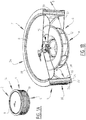
- Filter system 2 ( Figures 1A -B ) comprises a circumferential surface 4, bottom inlet 6, upper part or cover part 8.
- outlet surface 4 is provided with inclined openings 10. Airflow enters inlet 6 in direction A and leaves through outlet 4 in direction B.
- Fan 12 is driven by motor 14 that is activated and controlled by controller 16. Fan 12 directs air towards outlet surface 4.
- Electrostatic filter 18 comprises inner gaze, grid or screen 20 acting as first electrode and outer gaze, grid or screen 22 acting as second electrode.
- first electrode 20 is positively charged and second electrode 22 is negatively charged.
- First and second electrodes 20, 22 are provided at a distance relative to each other and a glass fibre filling material 24 is provided between electrodes 20, 22.
- filter housing 34 comprises bottom plate 36, top plate cover 8, ring 38 and outer surface grid 28. It will be understood that other configurations can also be envisaged in accordance with the invention.
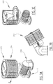
- Second embodiment 102 illustrates a filter system with filter housing 104 and inlet housing 106 that are integrated into a single housing.
- filter housing 104 and inlet housing 106 are rotatable around axis or shaft 108.
- a motor and/or fan 110 are provided in inlet housing 106.
- Supports 112 define inlet ports 114 that draw in air in direction A.
- Inside inlet housing 106 air is directed towards the inlet of filter housing 104 of filter system 102.
- Filter system 102 has a similar construction for electrode filter 116 and the optional plasma filter 118.
- Filter housing 104 is further provided with conical body 120, optionally provided with additional ribs. Air flow A is directed towards the outer surface in direction B with the use of conical body 120.
- outlet openings 122 extend in a horizontal direction relative to filter housing 104 and substantially parallel to top or cover plate 124.
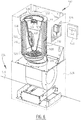
- a third embodiment of filter system 202 ( Figures 3A -C ) is similar to filter system 102 with the exception that filter housing 204 and inlet housing 206 are provided separately. In the illustrated embodiment this requires external connecting cable 208.
- the operation of filter system 202 is similar to the illustrated second embodiment 102.
- filter housing 304 has a rectangular or oval shape having width w and height h, wherein height h is smaller that width w.
- inlet housing 306 has an oval inlet opening and is provided with support 308. Inlet housing 306 can be slid into support 308. It will be understood that other embodiments are also possible.
- the oval or rectangular shape enables installing filter system 302 in relatively small spaces.
- a fifth embodiment filter system 402 ( Figures 5A -B ) is provided with filter housing 404 and inlet 406. Air flows in direction A and leaves direction B through outlet 408. Flow A is generated externally. Inside filter housing 404 there is provided fan 410 that starts rotating in the presence of flow A. therefore, fan 410 acts a a energy generating turbine capable of generating electricity to supply filters of filter system 402 operate in a similar manner as described earlier for other embodiments.
- a sixth embodiment filter system 502 comprises a filter housing 504 with an inlet 506, conical body 508, outlet surface 510 ( Figure 6 ).
- Conical body 508 is in the illustrated embodiment provided with ribs 512. It will be understood that ribs 512 can be omitted from conical body 508 and can also be provided with the other embodiments of filter system 2, 102, 202, 302, 402.
- Ozone generator 515 is connected to conical body 512.
- Cone 508 is provided with printed circuit board 514 which is operatively connected to connector 516.
- plasma generator 515 Arranged on cone 508 is plasma generator 515 provided with ozone plate 518 which is arranged with a clamping part in or on generator 515.
- Printed circuit board 514 is provided with sensors 520 on the side directed downward during use.
- Outer casing 510 is provided with bracket 522 for mounting on for instance an extractor hood.
- the filter inlet is provided with grate 506.
- Cover 530 is provided with connector 532, buttons 534 and a connection 536 for plug/adapter 538 which is connected to connector 516.
- Filter system 502 is connected to extractor hood 524 with extractor hood module 526 and air extraction module 528.
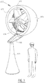
- ring shaped filter housing 604 is provided on pedestal 606 with arm 608.
- Filter system 602 acts as turbine with fan 610.
- the inside 612 of filter housing 604 is provided with ozone outlet 614 that are activated by fan 610.
- Filter system 602 can be used to filter outside air and/or outlet air of factories, for example.
- Operation of filter systems 2, 102, 202, 302, 402, 502, 602 preferably involves the use of control panel 540 with display 542.
- a filter system When a filter system is activated, for example with control 540 in several of the embodiments a fan and/or motor will draw in air via the inlets.
- sensors are arranged, optionally on the conical body, that will detect the presence, and type and/or level of contamination of the airflow. This signal is transmitted to the controller that can be cooperated into the encapsulated electronic space.
- the controller activates the ozone generator and/or electrostatic filter.
- the voltage used preferably lies in the range of 0.05 Volt-10 kV, more preferably in the range of 0.5-2 kV in normal ambient conditions.
- a voltage of 2-4 kV is employed for the optionally provided ozone generator.
- a standby mode is provided which can if desired be continuously "active".
- Filter system 2 can also be utilized in applications other than in extractor hood or building.
- the filter system can be applied to kitchen facility, more specifically an extractor hood, an exhaust pipe, in the outside air etc.
- the filter system is provided in open room such as in a vehicle, airplane, building, etc.
- Assembly of the filter system begins with a grating or mesh or grid, following which a second grating or mesh is provided at a short distance, for instance 40 mm, such that an inner and an outer annular cross-section are provided.
- This is the core of electrostatic filter 18, for example.
- the grids are connected.
- a glass fibre mat is preferably arranged in the intermediate space.
- Isolation mat 26 is arranged on the outer side.
- An ozone element 30 is subsequently arranged in a housing which is then optionally placed on conical element 508, for example.
- the conical element can then be placed in the interior, where after the wiring can be connected.
- An end plate can be arranged following placing. In a currently preferred embodiment a printed circuit board is then adhered fixedly in the filter housing.
- the end plate with sensor can subsequently be arranged so that filter system is mounted and can be applied.
- a filter system has been tested in an experiment in a kitchen. Recirculation was started at about 200 m 3 /hour for about 10 minutes prior to the cooking process in order to bring about a good circulation. In the applied situation the ozone binds the undesired particles with an efficiency of about 95%. The noise reduction realized was about 25% compared to the conventional extraction.
- the conical body can be applied to different embodiments or be omitted therefrom.
- the conical body can be provided with ribs or grooves optionally.
- the turbine operation or a fan can be provided in different embodiments of the filter system.
- different types of sensors can be applied and combined in the different embodiments.
- other features can be applied to the different embodiments.
- the filter according to the invention complies with the required standards, including the Dutch NEN 7120.
- the filter is quickly mountable, also when applied in existing and conventional extractor hoods.
- settings are preferably provided in adjustable and re-adjustable manner, preferably on a printed circuit board of the filter.
Landscapes
- Engineering & Computer Science (AREA)
- Chemical & Material Sciences (AREA)
- Combustion & Propulsion (AREA)
- Mechanical Engineering (AREA)
- General Engineering & Computer Science (AREA)
- Filtering Of Dispersed Particles In Gases (AREA)
- Electrostatic Separation (AREA)
Priority Applications (1)
| Application Number | Priority Date | Filing Date | Title |
|---|---|---|---|
| PL16798294T PL3532776T3 (pl) | 2016-10-25 | 2016-10-25 | Układ filtracyjny do filtrowania przepływu, okap wyciągowy zawierającego taki filtr i sposób filtrowania powietrza |
Applications Claiming Priority (1)
| Application Number | Priority Date | Filing Date | Title |
|---|---|---|---|
| PCT/NL2016/050736 WO2018080302A1 (en) | 2016-10-25 | 2016-10-25 | Filter system for filtering a flow, extractor hood comprising such filter, and method for filtering air |
Publications (2)
| Publication Number | Publication Date |
|---|---|
| EP3532776A1 EP3532776A1 (en) | 2019-09-04 |
| EP3532776B1 true EP3532776B1 (en) | 2020-12-23 |
Family
ID=57349104
Family Applications (1)
| Application Number | Title | Priority Date | Filing Date |
|---|---|---|---|
| EP16798294.1A Active EP3532776B1 (en) | 2016-10-25 | 2016-10-25 | Filter system for filtering a flow, extractor hood comprising such filter, and method for filtering air |
Country Status (4)
| Country | Link |
|---|---|
| EP (1) | EP3532776B1 (pl) |
| ES (1) | ES2850079T3 (pl) |
| PL (1) | PL3532776T3 (pl) |
| WO (1) | WO2018080302A1 (pl) |
Families Citing this family (9)
| Publication number | Priority date | Publication date | Assignee | Title |
|---|---|---|---|---|
| NL2021907B1 (en) * | 2018-10-31 | 2020-05-14 | Plasmamade B V | Modular climate unit and method for filtering a flow |
| IT201900006901A1 (it) * | 2019-05-16 | 2020-11-16 | Elica Spa | Metodo per determinare un grado di cottura di una pietanza ed elettrodomestico impiegante detto metodo |
| CN112082181B (zh) * | 2019-06-12 | 2021-08-31 | 广东合捷电器股份有限公司 | 净化器及抽油烟机 |
| CN110454839B (zh) * | 2019-09-04 | 2025-04-11 | 陈光辉 | 一种油烟净化装置 |
| WO2021109055A1 (zh) * | 2019-12-05 | 2021-06-10 | 深圳市迪尔安科技有限公司 | 一种厨房抽油烟机除油器 |
| EP3951276A1 (en) * | 2020-08-07 | 2022-02-09 | Investech Asia Limited | Purifier device and related purification method |
| NL2026940B1 (en) * | 2020-11-20 | 2022-07-01 | Plasmamade B V | Improved filter unit and method for filtering air |
| IT202100007526A1 (it) * | 2021-03-26 | 2022-09-26 | Elica Spa | Dispositivo per il trattamento dell’aria |
| TR2021020390A1 (tr) * | 2021-12-20 | 2023-06-21 | Bsh Ev Aletleri Sanayi Ve Ticaret Anonim Sirketi | Bi̇r bacaya sahi̇p bi̇r pi̇şi̇ri̇ci̇ ci̇haz |
Family Cites Families (5)
| Publication number | Priority date | Publication date | Assignee | Title |
|---|---|---|---|---|
| US5647890A (en) * | 1991-12-11 | 1997-07-15 | Yamamoto; Yujiro | Filter apparatus with induced voltage electrode and method |
| KR0164757B1 (ko) * | 1995-06-13 | 1999-01-15 | 김광호 | 공조장치의 살균집진장치와 그 방법 |
| CA2473540C (en) * | 2002-01-16 | 2008-12-02 | Vent Master (Europe) Limited | Ultraviolet lamp ventilation apparatus and method |
| WO2008057262A2 (en) * | 2006-10-26 | 2008-05-15 | Krichtafovitch Igor A | Range hood with electrostatically assisted air flow and filtering |
| NL2009138C2 (nl) | 2012-07-06 | 2014-01-07 | Martin Johan Sluis | Afzuigsysteem, afzuigkap en keuken voorzien daarvan, en werkwijze voor het afzuigen van lucht. |
-
2016
- 2016-10-25 PL PL16798294T patent/PL3532776T3/pl unknown
- 2016-10-25 ES ES16798294T patent/ES2850079T3/es active Active
- 2016-10-25 WO PCT/NL2016/050736 patent/WO2018080302A1/en not_active Ceased
- 2016-10-25 EP EP16798294.1A patent/EP3532776B1/en active Active
Non-Patent Citations (1)
| Title |
|---|
| None * |
Also Published As
| Publication number | Publication date |
|---|---|
| WO2018080302A1 (en) | 2018-05-03 |
| EP3532776A1 (en) | 2019-09-04 |
| ES2850079T3 (es) | 2021-08-25 |
| PL3532776T3 (pl) | 2021-06-28 |
Similar Documents
| Publication | Publication Date | Title |
|---|---|---|
| EP3532776B1 (en) | Filter system for filtering a flow, extractor hood comprising such filter, and method for filtering air | |
| EP2870413B1 (en) | Filter system, extractor hood and kitchen provided therewith, and method for extracting air | |
| EP3088808B1 (en) | Climate system, and building, vehicle or cooking facility provided therewith, and method for filtering air | |
| CN107435964B (zh) | 一种防止油烟逃逸的风幕系统 | |
| EP3385625B1 (en) | Air purifier | |
| US10900665B2 (en) | Combination appliance having a cooktop and steam extraction device | |
| CN109073250A (zh) | 风道和空气处理设备 | |
| KR102549299B1 (ko) | 유지 여과용 공기 필터 | |
| US20100051011A1 (en) | Vent hood for a cooking appliance | |
| CN107435962B (zh) | 一种开放式厨房空气环境的控制系统及其控制方法 | |
| WO2020156906A1 (en) | Air purifier | |
| KR101513538B1 (ko) | 자체 공기 정화 흡연부스 | |
| JP2013196869A (ja) | 空気清浄機能付き照明装置 | |
| NL2020193B1 (en) | Filter system for filtering a flow, extractor hood comprising such filter, and method for filtering air | |
| NL2017668B1 (en) | Filter system for filtering a flow, extractor hood comprising such filter, and method for filtering air | |
| WO2018233442A1 (zh) | 带有净化功能的空调器室内机及其控制方法 | |
| NL2014750B1 (en) | Climate system, and building, vehicle or cooking facility provided therewith, and method for filtering air. | |
| CN107435960B (zh) | 厨房空气净化系统 | |
| KR200480333Y1 (ko) | 청정온풍기 | |
| CN109340982B (zh) | 新风设备及其系统 | |
| US20220412586A1 (en) | Diffuser air purification unit | |
| CA2987679C (en) | Air filter for grease filtering | |
| CN204438384U (zh) | 除湿机 | |
| KR20220014261A (ko) | 휴대용 공기정화기 | |
| CN117553380A (zh) | 一种多功能室内空气净化处理控制系统 |
Legal Events
| Date | Code | Title | Description |
|---|---|---|---|
| STAA | Information on the status of an ep patent application or granted ep patent |
Free format text: STATUS: UNKNOWN |
|
| STAA | Information on the status of an ep patent application or granted ep patent |
Free format text: STATUS: THE INTERNATIONAL PUBLICATION HAS BEEN MADE |
|
| PUAI | Public reference made under article 153(3) epc to a published international application that has entered the european phase |
Free format text: ORIGINAL CODE: 0009012 |
|
| STAA | Information on the status of an ep patent application or granted ep patent |
Free format text: STATUS: REQUEST FOR EXAMINATION WAS MADE |
|
| 17P | Request for examination filed |
Effective date: 20190404 |
|
| AK | Designated contracting states |
Kind code of ref document: A1 Designated state(s): AL AT BE BG CH CY CZ DE DK EE ES FI FR GB GR HR HU IE IS IT LI LT LU LV MC MK MT NL NO PL PT RO RS SE SI SK SM TR |
|
| AX | Request for extension of the european patent |
Extension state: BA ME |
|
| DAV | Request for validation of the european patent (deleted) | ||
| DAX | Request for extension of the european patent (deleted) | ||
| RIC1 | Information provided on ipc code assigned before grant |
Ipc: F24F 11/00 20180101ALI20200630BHEP Ipc: B03C 3/017 20060101ALI20200630BHEP Ipc: B03C 3/49 20060101ALI20200630BHEP Ipc: B03C 3/36 20060101ALI20200630BHEP Ipc: F24F 110/00 20180101ALI20200630BHEP Ipc: F24F 11/30 20180101ALI20200630BHEP Ipc: B03C 3/06 20060101ALI20200630BHEP Ipc: F24C 15/20 20060101ALI20200630BHEP Ipc: B03C 3/41 20060101ALI20200630BHEP Ipc: F24F 3/16 20060101AFI20200630BHEP Ipc: B03C 3/155 20060101ALI20200630BHEP |
|
| GRAP | Despatch of communication of intention to grant a patent |
Free format text: ORIGINAL CODE: EPIDOSNIGR1 |
|
| STAA | Information on the status of an ep patent application or granted ep patent |
Free format text: STATUS: GRANT OF PATENT IS INTENDED |
|
| INTG | Intention to grant announced |
Effective date: 20200812 |
|
| GRAS | Grant fee paid |
Free format text: ORIGINAL CODE: EPIDOSNIGR3 |
|
| GRAA | (expected) grant |
Free format text: ORIGINAL CODE: 0009210 |
|
| STAA | Information on the status of an ep patent application or granted ep patent |
Free format text: STATUS: THE PATENT HAS BEEN GRANTED |
|
| AK | Designated contracting states |
Kind code of ref document: B1 Designated state(s): AL AT BE BG CH CY CZ DE DK EE ES FI FR GB GR HR HU IE IS IT LI LT LU LV MC MK MT NL NO PL PT RO RS SE SI SK SM TR |
|
| REG | Reference to a national code |
Ref country code: GB Ref legal event code: FG4D |
|
| REG | Reference to a national code |
Ref country code: DE Ref legal event code: R096 Ref document number: 602016050293 Country of ref document: DE |
|
| REG | Reference to a national code |
Ref country code: AT Ref legal event code: REF Ref document number: 1348110 Country of ref document: AT Kind code of ref document: T Effective date: 20210115 Ref country code: CH Ref legal event code: NV Representative=s name: NOVAGRAAF INTERNATIONAL SA, CH |
|
| REG | Reference to a national code |
Ref country code: IE Ref legal event code: FG4D |
|
| REG | Reference to a national code |
Ref country code: NL Ref legal event code: FP |
|
| REG | Reference to a national code |
Ref country code: SE Ref legal event code: TRGR |
|
| REG | Reference to a national code |
Ref country code: NL Ref legal event code: RC Free format text: DETAILS LICENCE OR PLEDGE: RIGHT OF PLEDGE, ESTABLISHED Name of requester: COOEPERATIEVE RABOBANK U.A. Effective date: 20210316 |
|
| REG | Reference to a national code |
Ref country code: NO Ref legal event code: T2 Effective date: 20201223 |
|
| PG25 | Lapsed in a contracting state [announced via postgrant information from national office to epo] |
Ref country code: FI Free format text: LAPSE BECAUSE OF FAILURE TO SUBMIT A TRANSLATION OF THE DESCRIPTION OR TO PAY THE FEE WITHIN THE PRESCRIBED TIME-LIMIT Effective date: 20201223 Ref country code: GR Free format text: LAPSE BECAUSE OF FAILURE TO SUBMIT A TRANSLATION OF THE DESCRIPTION OR TO PAY THE FEE WITHIN THE PRESCRIBED TIME-LIMIT Effective date: 20210324 Ref country code: RS Free format text: LAPSE BECAUSE OF FAILURE TO SUBMIT A TRANSLATION OF THE DESCRIPTION OR TO PAY THE FEE WITHIN THE PRESCRIBED TIME-LIMIT Effective date: 20201223 |
|
| PG25 | Lapsed in a contracting state [announced via postgrant information from national office to epo] |
Ref country code: BG Free format text: LAPSE BECAUSE OF FAILURE TO SUBMIT A TRANSLATION OF THE DESCRIPTION OR TO PAY THE FEE WITHIN THE PRESCRIBED TIME-LIMIT Effective date: 20210323 Ref country code: LV Free format text: LAPSE BECAUSE OF FAILURE TO SUBMIT A TRANSLATION OF THE DESCRIPTION OR TO PAY THE FEE WITHIN THE PRESCRIBED TIME-LIMIT Effective date: 20201223 |
|
| PG25 | Lapsed in a contracting state [announced via postgrant information from national office to epo] |
Ref country code: HR Free format text: LAPSE BECAUSE OF FAILURE TO SUBMIT A TRANSLATION OF THE DESCRIPTION OR TO PAY THE FEE WITHIN THE PRESCRIBED TIME-LIMIT Effective date: 20201223 |
|
| REG | Reference to a national code |
Ref country code: LT Ref legal event code: MG9D |
|
| PG25 | Lapsed in a contracting state [announced via postgrant information from national office to epo] |
Ref country code: RO Free format text: LAPSE BECAUSE OF FAILURE TO SUBMIT A TRANSLATION OF THE DESCRIPTION OR TO PAY THE FEE WITHIN THE PRESCRIBED TIME-LIMIT Effective date: 20201223 Ref country code: SK Free format text: LAPSE BECAUSE OF FAILURE TO SUBMIT A TRANSLATION OF THE DESCRIPTION OR TO PAY THE FEE WITHIN THE PRESCRIBED TIME-LIMIT Effective date: 20201223 Ref country code: PT Free format text: LAPSE BECAUSE OF FAILURE TO SUBMIT A TRANSLATION OF THE DESCRIPTION OR TO PAY THE FEE WITHIN THE PRESCRIBED TIME-LIMIT Effective date: 20210423 Ref country code: CZ Free format text: LAPSE BECAUSE OF FAILURE TO SUBMIT A TRANSLATION OF THE DESCRIPTION OR TO PAY THE FEE WITHIN THE PRESCRIBED TIME-LIMIT Effective date: 20201223 Ref country code: EE Free format text: LAPSE BECAUSE OF FAILURE TO SUBMIT A TRANSLATION OF THE DESCRIPTION OR TO PAY THE FEE WITHIN THE PRESCRIBED TIME-LIMIT Effective date: 20201223 Ref country code: SM Free format text: LAPSE BECAUSE OF FAILURE TO SUBMIT A TRANSLATION OF THE DESCRIPTION OR TO PAY THE FEE WITHIN THE PRESCRIBED TIME-LIMIT Effective date: 20201223 Ref country code: LT Free format text: LAPSE BECAUSE OF FAILURE TO SUBMIT A TRANSLATION OF THE DESCRIPTION OR TO PAY THE FEE WITHIN THE PRESCRIBED TIME-LIMIT Effective date: 20201223 |
|
| REG | Reference to a national code |
Ref country code: ES Ref legal event code: FG2A Ref document number: 2850079 Country of ref document: ES Kind code of ref document: T3 Effective date: 20210825 |
|
| REG | Reference to a national code |
Ref country code: DE Ref legal event code: R097 Ref document number: 602016050293 Country of ref document: DE |
|
| PG25 | Lapsed in a contracting state [announced via postgrant information from national office to epo] |
Ref country code: IS Free format text: LAPSE BECAUSE OF FAILURE TO SUBMIT A TRANSLATION OF THE DESCRIPTION OR TO PAY THE FEE WITHIN THE PRESCRIBED TIME-LIMIT Effective date: 20210423 |
|
| PG25 | Lapsed in a contracting state [announced via postgrant information from national office to epo] |
Ref country code: AL Free format text: LAPSE BECAUSE OF FAILURE TO SUBMIT A TRANSLATION OF THE DESCRIPTION OR TO PAY THE FEE WITHIN THE PRESCRIBED TIME-LIMIT Effective date: 20201223 |
|
| PLBE | No opposition filed within time limit |
Free format text: ORIGINAL CODE: 0009261 |
|
| STAA | Information on the status of an ep patent application or granted ep patent |
Free format text: STATUS: NO OPPOSITION FILED WITHIN TIME LIMIT |
|
| PG25 | Lapsed in a contracting state [announced via postgrant information from national office to epo] |
Ref country code: DK Free format text: LAPSE BECAUSE OF FAILURE TO SUBMIT A TRANSLATION OF THE DESCRIPTION OR TO PAY THE FEE WITHIN THE PRESCRIBED TIME-LIMIT Effective date: 20201223 |
|
| 26N | No opposition filed |
Effective date: 20210924 |
|
| PG25 | Lapsed in a contracting state [announced via postgrant information from national office to epo] |
Ref country code: SI Free format text: LAPSE BECAUSE OF FAILURE TO SUBMIT A TRANSLATION OF THE DESCRIPTION OR TO PAY THE FEE WITHIN THE PRESCRIBED TIME-LIMIT Effective date: 20201223 |
|
| PG25 | Lapsed in a contracting state [announced via postgrant information from national office to epo] |
Ref country code: IS Free format text: LAPSE BECAUSE OF FAILURE TO SUBMIT A TRANSLATION OF THE DESCRIPTION OR TO PAY THE FEE WITHIN THE PRESCRIBED TIME-LIMIT Effective date: 20210423 |
|
| PG25 | Lapsed in a contracting state [announced via postgrant information from national office to epo] |
Ref country code: MC Free format text: LAPSE BECAUSE OF FAILURE TO SUBMIT A TRANSLATION OF THE DESCRIPTION OR TO PAY THE FEE WITHIN THE PRESCRIBED TIME-LIMIT Effective date: 20201223 |
|
| PG25 | Lapsed in a contracting state [announced via postgrant information from national office to epo] |
Ref country code: IE Free format text: LAPSE BECAUSE OF NON-PAYMENT OF DUE FEES Effective date: 20211025 |
|
| REG | Reference to a national code |
Ref country code: AT Ref legal event code: UEP Ref document number: 1348110 Country of ref document: AT Kind code of ref document: T Effective date: 20201223 |
|
| P01 | Opt-out of the competence of the unified patent court (upc) registered |
Effective date: 20230516 |
|
| PG25 | Lapsed in a contracting state [announced via postgrant information from national office to epo] |
Ref country code: CY Free format text: LAPSE BECAUSE OF FAILURE TO SUBMIT A TRANSLATION OF THE DESCRIPTION OR TO PAY THE FEE WITHIN THE PRESCRIBED TIME-LIMIT Effective date: 20201223 |
|
| PG25 | Lapsed in a contracting state [announced via postgrant information from national office to epo] |
Ref country code: HU Free format text: LAPSE BECAUSE OF FAILURE TO SUBMIT A TRANSLATION OF THE DESCRIPTION OR TO PAY THE FEE WITHIN THE PRESCRIBED TIME-LIMIT; INVALID AB INITIO Effective date: 20161025 |
|
| PG25 | Lapsed in a contracting state [announced via postgrant information from national office to epo] |
Ref country code: MK Free format text: LAPSE BECAUSE OF FAILURE TO SUBMIT A TRANSLATION OF THE DESCRIPTION OR TO PAY THE FEE WITHIN THE PRESCRIBED TIME-LIMIT Effective date: 20201223 |
|
| PG25 | Lapsed in a contracting state [announced via postgrant information from national office to epo] |
Ref country code: MT Free format text: LAPSE BECAUSE OF FAILURE TO SUBMIT A TRANSLATION OF THE DESCRIPTION OR TO PAY THE FEE WITHIN THE PRESCRIBED TIME-LIMIT Effective date: 20201223 |
|
| REG | Reference to a national code |
Ref country code: CH Ref legal event code: U11 Free format text: ST27 STATUS EVENT CODE: U-0-0-U10-U11 (AS PROVIDED BY THE NATIONAL OFFICE) Effective date: 20251101 |
|
| PGFP | Annual fee paid to national office [announced via postgrant information from national office to epo] |
Ref country code: LU Payment date: 20251027 Year of fee payment: 10 Ref country code: NL Payment date: 20251026 Year of fee payment: 10 |
|
| PGFP | Annual fee paid to national office [announced via postgrant information from national office to epo] |
Ref country code: DE Payment date: 20251029 Year of fee payment: 10 |
|
| PGFP | Annual fee paid to national office [announced via postgrant information from national office to epo] |
Ref country code: GB Payment date: 20251027 Year of fee payment: 10 |
|
| PGFP | Annual fee paid to national office [announced via postgrant information from national office to epo] |
Ref country code: NO Payment date: 20251029 Year of fee payment: 10 |
|
| PGFP | Annual fee paid to national office [announced via postgrant information from national office to epo] |
Ref country code: AT Payment date: 20251029 Year of fee payment: 10 |
|
| PGFP | Annual fee paid to national office [announced via postgrant information from national office to epo] |
Ref country code: IT Payment date: 20251021 Year of fee payment: 10 |
|
| PGFP | Annual fee paid to national office [announced via postgrant information from national office to epo] |
Ref country code: FR Payment date: 20251027 Year of fee payment: 10 |
|
| PGFP | Annual fee paid to national office [announced via postgrant information from national office to epo] |
Ref country code: TR Payment date: 20251007 Year of fee payment: 10 Ref country code: BE Payment date: 20251027 Year of fee payment: 10 |
|
| PGFP | Annual fee paid to national office [announced via postgrant information from national office to epo] |
Ref country code: SE Payment date: 20251027 Year of fee payment: 10 Ref country code: CH Payment date: 20251101 Year of fee payment: 10 |
|
| PGFP | Annual fee paid to national office [announced via postgrant information from national office to epo] |
Ref country code: PL Payment date: 20251003 Year of fee payment: 10 |
|
| PGFP | Annual fee paid to national office [announced via postgrant information from national office to epo] |
Ref country code: ES Payment date: 20251103 Year of fee payment: 10 |