EP3532723B1 - Magnetventil für eine verbrennungskraftmaschine - Google Patents
Magnetventil für eine verbrennungskraftmaschine Download PDFInfo
- Publication number
- EP3532723B1 EP3532723B1 EP17772719.5A EP17772719A EP3532723B1 EP 3532723 B1 EP3532723 B1 EP 3532723B1 EP 17772719 A EP17772719 A EP 17772719A EP 3532723 B1 EP3532723 B1 EP 3532723B1
- Authority
- EP
- European Patent Office
- Prior art keywords
- solenoid valve
- combustion engine
- internal combustion
- cap
- plunger
- Prior art date
- Legal status (The legal status is an assumption and is not a legal conclusion. Google has not performed a legal analysis and makes no representation as to the accuracy of the status listed.)
- Active
Links
Images
Classifications
-
- F—MECHANICAL ENGINEERING; LIGHTING; HEATING; WEAPONS; BLASTING
- F02—COMBUSTION ENGINES; HOT-GAS OR COMBUSTION-PRODUCT ENGINE PLANTS
- F02M—SUPPLYING COMBUSTION ENGINES IN GENERAL WITH COMBUSTIBLE MIXTURES OR CONSTITUENTS THEREOF
- F02M61/00—Fuel-injectors not provided for in groups F02M39/00 - F02M57/00 or F02M67/00
- F02M61/16—Details not provided for in, or of interest apart from, the apparatus of groups F02M61/02 - F02M61/14
- F02M61/168—Assembling; Disassembling; Manufacturing; Adjusting
-
- F—MECHANICAL ENGINEERING; LIGHTING; HEATING; WEAPONS; BLASTING
- F16—ENGINEERING ELEMENTS AND UNITS; GENERAL MEASURES FOR PRODUCING AND MAINTAINING EFFECTIVE FUNCTIONING OF MACHINES OR INSTALLATIONS; THERMAL INSULATION IN GENERAL
- F16K—VALVES; TAPS; COCKS; ACTUATING-FLOATS; DEVICES FOR VENTING OR AERATING
- F16K1/00—Lift valves or globe valves, i.e. cut-off apparatus with closure members having at least a component of their opening and closing motion perpendicular to the closing faces
- F16K1/32—Details
- F16K1/34—Cutting-off parts, e.g. valve members, seats
- F16K1/36—Valve members
-
- F—MECHANICAL ENGINEERING; LIGHTING; HEATING; WEAPONS; BLASTING
- F16—ENGINEERING ELEMENTS AND UNITS; GENERAL MEASURES FOR PRODUCING AND MAINTAINING EFFECTIVE FUNCTIONING OF MACHINES OR INSTALLATIONS; THERMAL INSULATION IN GENERAL
- F16K—VALVES; TAPS; COCKS; ACTUATING-FLOATS; DEVICES FOR VENTING OR AERATING
- F16K31/00—Actuating devices; Operating means; Releasing devices
- F16K31/02—Actuating devices; Operating means; Releasing devices electric; magnetic
- F16K31/06—Actuating devices; Operating means; Releasing devices electric; magnetic using a magnet, e.g. diaphragm valves, cutting off by means of a liquid
- F16K31/0644—One-way valve
- F16K31/0655—Lift valves
-
- F—MECHANICAL ENGINEERING; LIGHTING; HEATING; WEAPONS; BLASTING
- F02—COMBUSTION ENGINES; HOT-GAS OR COMBUSTION-PRODUCT ENGINE PLANTS
- F02M—SUPPLYING COMBUSTION ENGINES IN GENERAL WITH COMBUSTIBLE MIXTURES OR CONSTITUENTS THEREOF
- F02M2200/00—Details of fuel-injection apparatus, not otherwise provided for
- F02M2200/80—Fuel injection apparatus manufacture, repair or assembly
- F02M2200/8053—Fuel injection apparatus manufacture, repair or assembly involving mechanical deformation of the apparatus or parts thereof
-
- F—MECHANICAL ENGINEERING; LIGHTING; HEATING; WEAPONS; BLASTING
- F02—COMBUSTION ENGINES; HOT-GAS OR COMBUSTION-PRODUCT ENGINE PLANTS
- F02M—SUPPLYING COMBUSTION ENGINES IN GENERAL WITH COMBUSTIBLE MIXTURES OR CONSTITUENTS THEREOF
- F02M2200/00—Details of fuel-injection apparatus, not otherwise provided for
- F02M2200/80—Fuel injection apparatus manufacture, repair or assembly
- F02M2200/8061—Fuel injection apparatus manufacture, repair or assembly involving press-fit, i.e. interference or friction fit
Definitions
- the present invention relates to a solenoid valve for an internal combustion engine with a housing, a coil, an armature which can be moved axially by energizing the coil, and a tappet which is formed on the valve body and can be moved with the armature.
- Such solenoid valves are often used to supply the piston heads of an internal combustion engine with cooling medium by opening or closing the valve.
- the JP 2013-29147 A discloses a solenoid valve having a housing in which a coil wound on a bobbin is disposed.
- the coil carrier has a sleeve opening in which a sliding bush is arranged.
- a magnet armature can be moved axially inside the sliding bush by energizing the coil.
- the magnet armature is connected via a connecting rod to a tappet, which opens or closes a valve passage through axial movement.
- the ram is surrounded by a compression spring which is prestressed against a radial widening formed by the ram. When the coil is energized, the compression spring applies a compressive force to the plunger, counter to the force of the magnet armature, so that when the magnet armature is not energized, it and the plunger are moved into a rest position.
- an electromagnetic directional control valve which has a two-part tappet.
- the two parts of the ram are essentially tubular and are pushed over one another.
- the DE 10 2008 002 562 A1 discloses an electric spool valve, the spool of which has a conical opening into which a stem protrudes with its opposite end against the anchor. Like a valve rod, this stem serves to transmit movement.
- a similar structure is also in the DE 10 2014 214 362 A1 disclosed in which a cup stem is connected to the armature and abuts axially against a spool of the valve.
- the object of the present invention is therefore to create a solenoid valve for an internal combustion engine which can be produced economically.
- the plunger is designed in two parts, with a first part of the plunger being a tube and a second part of the plunger being a cap.
- the cap and the tube are thus independent of each other.
- a cap within the meaning of the present invention is to be understood as a component with which something can be covered.
- one end of the tube is covered with the cap.
- the two-part design of the ram allows the cap and the tube to be manufactured independently of one another. This allows the manufacturing process and material to be optimized for each part. As a result, the tappet and thus the solenoid valve can be manufactured more economically.
- the cap of the plunger is thus cup-shaped and has a radially widening edge that rests on the tube and rests with a lateral surface of the cup-shaped cap on an inner wall of the tube.
- the cap is thus retained on the tube in an axial direction of the tube by the radially expanding rim.
- a force can thus be transmitted to the tube via the cap in this axial direction, so that the plunger with the armature can be moved axially in a sliding bush via a connecting rod which is in contact with the cup-shaped cap.
- the lateral surface is understood to mean the surface that radially delimits the cup-shaped cap.
- the arrangement of the lateral surface to the inner wall according to the invention achieves maximum surface contact, as a result of which a connection between the tube and the cap is improved.
- a centric arrangement of the cap in the tube is achieved through the contact of the lateral surface with the inner wall of the tube.
- the tube is a turned part.
- a turned part is understood to mean that the tube is manufactured by means of a machining manufacturing process in which the part rotates around its own axis. By means of such a method, the tube can be produced easily and economically.
- the cap is preferably a deep-drawn stamped part.
- the cap is thus produced by the process steps of stamping and deep-drawing. In mass production, these process steps require little time, so that the output of caps is very high. This reduces the production cost of the solenoid valve.
- the tube and the cap are connected to one another by means of a press fit.
- a press fit By means of a press fit, a non-positive connection between the tube and the cap can be produced in a simple and economical manner. As a result, production costs can be reduced.
- At least one pressure compensation bore is advantageously formed in a base of the cup-shaped cap.
- the pressure compensation hole penetrates the bottom of the cup-shaped cap in a preferably axial direction.
- An underside of the bottom of the cup-shaped cap is thereby fluidly connected to a top of the cup-shaped cap.
- a pressure difference on the underside of the bottom of the cup-shaped cap to the top of the cup-shaped cap is compensated via the pressure equalization hole.
- the ram is preferably guided in a sliding bush and can be moved.
- the slide bushing improves the sliding properties of the tappet in the housing.
- the solenoid valve has a compression spring that rests against the radially expanding edge of the cup-shaped cap, the compression spring exerting a force against the direction of movement of the armature when the coil is energized. raises.
- the radially widening edge protrudes radially beyond the tube to such an extent that a bearing surface for the compression spring is formed.
- the compression spring thus ensures that the plunger can also be moved between two axial end positions counter to the force of the electromagnet, so that the valve can be opened and closed.
- the cap is preferably made of sheet metal.
- Sheet metal is a cheap material, which is also easy to process. This allows the solenoid valve to be manufactured more economically.
- the housing is designed in two parts, with a first housing part having the sliding bush and the plunger and the coil carrier and the armature being arranged in a second housing part, and the first housing part being mechanically connected to the second housing part.
- the electromagnet can thus be used for different connections.
- each part can be replaced individually, so that the entire solenoid valve does not have to be replaced.
- a solenoid valve for an internal combustion engine is thus created which can be produced economically.
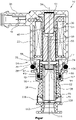
- the figure shows a sectional view of a solenoid valve 10 according to the invention for an internal combustion engine.
- the solenoid valve 10 comprises a housing 14 which is formed in two parts from a first housing part 18 which serves as a valve housing and a second housing part 22 . Both housing parts 18, 22 are non-positively connected at a connection point 26 via a laser welded connection, for example.
- a first O-ring 28 is arranged, which seals the solenoid valve 10 to the outside.
- a coil 30 is arranged inside the second housing part 22 and is formed from a coil wire which is wound onto a coil carrier 34 .
- the second housing part 22 forms a plug 38 with plug contacts 42, via which the coil 30 can be energized.
- the coil 30 has a coil carrier bore 46 in which a guide sleeve 47 is arranged, which extends into the first housing part 18 .
- a second O-ring 49 is arranged between a housing outer wall 48 of the first housing part 18 and the guide sleeve 47, so that a housing interior 50 is sealed off from the outside is.
- An armature 51 is arranged in the guide sleeve 47 and can be moved axially to a core 56 by energizing the coil 30 in the direction of a central axis 54 of the second housing part 22 .
- a metal slide bushing 58 is arranged in a bore 62 of the first housing part 18 in the first housing part 18 .
- the slide bushing 58 receives a two-part plunger 66 forming a valve body, a first part of the plunger 66 being a tube 70 and a second part being a cup-shaped cap 74 .
- the pot-shaped cap 74 which is a deep-drawn stamped part, forms a radially widening edge 78, which rests on the tube 70, which is designed as a turned part.
- the cup-shaped cap 74 is connected to the tube 70 via a press fit, with a lateral surface 82 of the cup-shaped cap 74 bearing against an inner wall 86 of the tube 70 .
- several pressure equalization bores 94 are formed, via which a pressure difference between the bottom of the cap and the top of the cap is prevented, so that the valve can be switched with little force.
- the plunger 66 can be moved axially in the sliding bush 58 with the armature 51 via a connecting rod 98 which is in contact with the cup-shaped cap 74 .
- a compression spring 106 is arranged under tension, which applies a force to the plunger 66 in the direction of the armature 51, so that the plunger 66 is constantly pressed against the connecting rod 98.
- the manufacturability of the tappet is simplified by a two-part design of the tappet. As a result, the manufacturing cost of the solenoid valve can be reduced.
- the scope of protection is not limited to the exemplary embodiments of a solenoid valve described, but that various modifications and design changes are conceivable.
- the cap can also be connected to the tube via a welded connection.
Landscapes
- Engineering & Computer Science (AREA)
- General Engineering & Computer Science (AREA)
- Mechanical Engineering (AREA)
- Manufacturing & Machinery (AREA)
- Chemical & Material Sciences (AREA)
- Combustion & Propulsion (AREA)
- Magnetically Actuated Valves (AREA)
Description
- Die vorliegende Erfindung betrifft ein Magnetventil für eine Verbrennungskraftmaschine mit einem Gehäuse, einer Spule, einem Anker, welcher durch Bestromung der Spule axial bewegbar ist, und einem am Ventilkörper ausbildenden Stößel, welcher mit dem Anker bewegbar ist.
- Solche Magnetventile werden häufig dazu eingesetzt, durch Öffnen oder Schließen des Ventils die Kolbenböden einer Verbrennungskraftmaschine mit Kühlmedium zu versorgen.
- Die
JP 2013-29147 A - Des Weiteren ist aus der
DE 10 2009 006 353 A1 ein elektromagnetisches Wegeventil bekannt, welches einen zweiteiligen Stößel aufweist. Die beiden Teile des Stößels sind im Wesentlichen rohrförmig ausgeführt und werden übereinander geschoben. - Die
DE 10 2008 002 562 A1 offenbart ein elektrisches Schieberventil, dessen Schieber eine konische Öffnung aufweist, in die ein Schaft ragt, der mit seinem entgegengesetzten Ende gegen den Anker anliegt. Dieser Schaft dient wie eine Ventilstange zur Bewegungsübertragung. - Ein ähnlicher Aufbau wird auch in der
DE 10 2014 214 362 A1 offenbart, in der ein Tassenschaft mit dem Anker verbunden ist und axial gegen einen Schieber des Ventils anliegt. - Zusätzlich wird in der
US 2012/0186547 A1 ein Elektromagnetventil beschrieben, an dessen Schieber ein ringförmiger Stopper befestigt ist. - Obwohl der Stand der Technik viele verschiedene Lösungen für ein Magnetventil vorschlägt, besteht ständig der Bedarf an noch preiswerteren Magnetventilen. Ein Magnetventil wird regelmäßig dann preiswerter, wenn es wirtschaftlicher herstellbar ist.
- Die Aufgabe der vorliegenden Erfindung liegt somit darin, ein Magnetventil für eine Verbrennungskraftmaschine zu schaffen, welches wirtschaftlich herstellbar ist.
- Diese Aufgabe wird durch ein Magnetventil für eine Verbrennungskraftmaschine mit den Merkmalen des Anspruchs 1 gelöst.
- Bei dem erfindungsgemäßen Magnetventil ist der Stößel zweiteilig ausgebildet, wobei ein erstes Teil des Stößels ein Rohr und ein zweites Teil des Stößels eine Kappe ist. Die Kappe und das Rohr sind somit unabhängig voneinander. Unter einer Kappe im Sinne der vorliegenden Erfindung ist ein Bauteil zu verstehen, mit welchem etwas abgedeckt werden kann. Erfindungsgemäß wird ein Ende des Rohres mit Hilfe der Kappe abgedeckt. Durch die Zweiteiligkeit des Stößels können die Kappe und das Rohr unabhängig voneinander hergestellt werden. Dadurch können das Herstellungsverfahren und das Material für das jeweilige Teil optimiert werden. Dadurch kann der Stößel und damit das Magnetventil wirtschaftlicher hergestellt werden. Die Kappe des Stößels ist somit topfförmig ausgebildet und weist einen sich radial erweiternden Rand, der auf dem Rohr aufliegt, auf und liegt mit einer Mantelfläche der topfförmigen Kappe an einer Innenwand des Rohres an. Die Kappe wird somit in einer axialen Richtung des Rohres durch den radial erweiternden Rand auf dem Rohr gehalten. In dieser axialen Richtung kann somit über die Kappe eine Kraft auf das Rohr übertragen werden, so dass der Stößel mit dem Anker über eine Verbindungsstange, welche mit der topfförmigen Kappe in Kontakt ist, in einer Gleitbuchse axial bewegbar ist. Als Mantelfläche wird dabei die die topfförmige Kappe radial begrenzende Fläche verstanden. Durch die erfindungsgemäße Anordnung von Mantelfläche zu Innenwand wird ein maximaler flächenmäßiger Kontakt erzielt, wodurch eine Verbindung zwischen Rohr und Kappe verbessert ist. Zusätzlich wird durch den Kontakt der Mantelfläche mit der Innenwand des Rohres eine zentrische Anordnung von der Kappe in dem Rohr erzielt.
- In einer bevorzugten Ausführung der Erfindung ist das Rohr ein Drehteil. Unter einem Drehteil wird verstanden, dass das Rohr mittels eines zerspannenden Fertigungsverfahrens hergestellt wird, bei dem sich das Teil um die eigene Achse dreht. Mittels eines solchen Verfahrens, ist das Rohr einfach und wirtschaftlich herstellbar.
- Vorzugsweise ist die Kappe ein Tiefzieh-Stanzteil. Die Kappe wird somit durch die Verfahrensschritte des Stanzens und des Tiefziehens hergestellt. Diese Verfahrensschritte benötigen bei einer Massenfertigung wenig Zeit, so dass der Ausstoß an Kappen sehr hoch ist. Dadurch werden die Produktionskosten des Magnetventils gesenkt.
- In einer bevorzugten Weiterbildung der Erfindung sind das Rohr und die Kappe über eine Presspassung miteinander verbunden. Mittels einer Presspassung, kann auf einfache und wirtschaftliche Weise eine kraftschlüssige Verbindung zwischen Rohr und Kappe hergestellt werden. Dadurch können die Produktionskosten gesenkt werden.
- Vorteilhafterweise ist in einem Boden der topfförmigen Kappe wenigstens eine Druckausgleichsbohrung ausgebildet. Die Druckausgleichsbohrung durchdringt dabei den Boden der topfförmigen Kappe in vorzugsweise axialer Richtung. Eine Unterseite des Bodens der topfförmigen Kappe wird dadurch mit einer Oberseite der topfförmigen Kappe fluidisch verbunden. Dadurch wird ein Druckunterschied an der Unterseite des Bodens der topfförmigen Kappe zu der Oberseite der topfförmigen Kappe über die Druckausgleichsbohrung ausgeglichen.
- Der Stößel ist vorzugsweise in einer Gleitbuchse geführt bewegbar. Durch die Gleitbuchse werden die Gleiteigenschaften des Stößels im Gehäuse verbessert.
- In einer vorteilhaften Ausgestaltung weist das Magnetventil eine Druckfeder auf, die gegen den radial erweiternden Rand der topfförmigen Kappe vorgespannt anliegt, wobei die Druckfeder eine Kraft entgegen einer Bewegungsrichtung des Ankers bei Bestromung der Spule auf den Stöße! aufbringt. Der radial erweiternde Rand überragt dabei das Rohr radial so weit, dass eine Auflagefläche für die Druckfeder gebildet wird. Durch die Druckfeder wird somit sichergestellt, dass der Stößel auch entgegen der Kraft des Elektromagneten zwischen zwei axialen Endpositionen bewegbar ist, so dass das Ventil zu öffnen und zu schließen ist.
- Die Kappe besteht vorzugsweise aus Blech. Blech ist ein günstiges Material, welches zudem leicht zu verarbeiten ist. Dadurch kann das Magnetventil wirtschaftlicher hergestellt werden.
- Besonders vorteilhaft ist es, dass das Gehäuse zweiteilig ausgebildet ist, wobei ein erstes Gehäuseteil die Gleitbuchse und den Stößel aufweist und in einem zweiten Gehäuseteil der Spulenträger und der Anker angeordnet sind, und dass das erste Gehäuseteil mit dem zweiten Gehäuseteil mechanisch verbunden ist. Der Elektromagnet ist dadurch für unterschiedliche Anschlüsse nutzbar. Darüber hinaus ist bei einem Schadensfall jedes Teil einzeln austauschbar, so dass nicht das ganze Magnetventil ausgetauscht werden muss.
- Es wird somit ein Magnetventil für eine Verbrennungskraftmaschine geschaffen, welches wirtschaftlich herstellbar ist.
- Weitere Einzelheiten und Vorteile der vorliegenden Erfindung ergeben sich aus der nachfolgenden Beschreibung des Ausführungsbeispiels in Verbindung mit der Zeichnung. In dieser zeigt:
- Figur:
- Schnittdarstellung eines erfindungsgemäßen Magnetventils für eine Verbrennungskraftmaschine.
- Die Figur zeigt eine Schnittdarstellung eines erfindungsgemäßen Magnetventils 10 für eine Verbrennungskraftmaschine. Das Magnetventil 10 umfasst ein Gehäuse 14, welches zweiteilig aus einem ersten Gehäuseteil 18, welches als Ventilgehäuse dient, und einem zweiten Gehäuseteil 22 gebildet ist. Beide Gehäuseteile 18, 22 sind an einer Verbindungsstelle 26 kraftschlüssig über beispielsweise eine Laserschweißverbindung verbunden. In dem Bereich der Verbindungsstelle 26 ist ein erster O-Ring 28 angeordnet, welcher das Magnetventil 10 nach außen hin abdichtet.
- Innerhalb des zweiten Gehäuseteils 22 ist eine Spule 30 angeordnet, welche aus einem Spulendraht gebildet ist, der auf einen Spulenträger 34 gewickelt ist. Das zweite Gehäuseteil 22 bildet einen Stecker 38 mit Steckkontakten 42 aus, über welchen die Spule 30 bestrombar ist. Die Spule 30 weist eine Spulenträgerbohrung 46 auf, in weicher eine Führungshülse 47 angeordnet ist, welche sich bis in das erste Gehäuseteil 18 erstreckt. Zwischen einer Gehäuseaußenwand 48 des ersten Gehäuseteils 18 und der Führungshülse 47 ist ein zweiter O-Ring 49 angeordnet, so dass ein Gehäuseinnenraum 50 nach außen abgedichtet ist. In der Führungshülse 47 ist ein Anker 51 angeordnet, der durch Bestromung der Spule 30 in Richtung einer Mittelachse 54 des zweiten Gehäuseteils 22 axial zu einem Kern 56 bewegbar ist.
- In dem ersten Gehäuseteil 18 ist eine metallische Gleitbuchse 58 in einer Bohrung 62 des ersten Gehäuseteils 18 angeordnet. Die Gleitbuchse 58 nimmt einen, einen Ventilkörper ausbildenden, zweiteiligen Stößel 66 auf, wobei ein erstes Teil des Stößels 66 ein Rohr 70 und ein zweites Teil eine topfförmige Kappe 74 ist. Die topfförmige Kappe 74, welche ein Tiefzieh-Stanzteil ist, bildet einen radial erweiternden Rand 78 aus, welcher auf dem als Drehteil ausgeführten Rohr 70 aufliegt. Die topfförmige Kappe 74 ist über eine Presspassung mit dem Rohr 70 verbunden, wobei eine Mantelfläche 82 der topfförmigen Kappe 74 an einer Innenwand 86 des Rohres 70 anliegt. In einem Boden 90 der topfförmigen Kappe 74 sind mehrere Druckausgleichsbohrungen 94 ausgebildet, über welche ein Druckunterschied zwischen der Unterseite der Kappe und der Oberseite der Kappe verhindert wird, so dass das Ventil mit geringer Kraft geschaltet werden kann.
- Der Stößel 66 ist mit dem Anker 51 über eine Verbindungsstange 98, welche mit der topfförmigen Kappe 74 in Kontakt ist, in der Gleitbuchse 58 axial bewegbar. Zwischen dem radial erweiternden Rand 78 der topfförmigen Kappe 74, welcher das Rohr 70 radial überragt, und einem Absatz 102 im ersten Gehäuseteil 18, ist eine Druckfeder 106 vorgespannt angeordnet, welche auf den Stößel 66 eine Kraft in Richtung des Ankers 51 aufbringt, so dass der Stößel 66 ständig gegen die Verbindungsstange 98 gedrückt wird. Ein zu dem Anker 51 entgegengesetztes axiales Ende des Stößels 66 wirkt mit einem abgerundeten Ventilsitz 110 zusammen, wobei das Rohr 70 mit einer dünnen Kante 112 auf dem Ventilsitz 110 aufliegt, so dass beim Öffnen eine durch die Strömung auf den Stößel 66 wirkende Schließkraft geringer ist. Im nicht bestromten Zustand ist eine Verbindung zwischen einem in axialer Richtung am Ende des Gehäuses 18 angeordneten Ventileingang 114 und einem in radialer Richtung am Ende des Gehäuses 18 angeordneten Ventilausgang 118 freigegeben. Im bestromten Zustand ist der Stößel 66 mit dem Ventilsitz 110 in Kontakt und verschließt die Verbindung zwischen Ventileingang 114 und Ventilausgang 118.
- Bei dem beschriebenen erfindungsgemäßen Magnetventil wird durch einen zweiteiligen Aufbau des Stößels die Herstellbarkeit von diesem vereinfacht. Dadurch können die Herstellungskosten des Magnetventils gesenkt werden.
- Es sollte deutlich sein, dass der Schutzbereich nicht auf die beschriebenen Ausführungsbeispiele eines Magnetventils beschränkt ist, sondern verschiedene Modifikationen und konstruktive Änderungen denkbar sind. Beispielsweise kann die Kappe auch über eine Schweißverbindung mit dem Rohr verbunden sein.
-
- 10
- Magnetventil
- 14
- Gehäuse
- 18
- erstes Gehäuseteil
- 22
- zweites Gehäuseteil
- 26
- Verbindungsstelle
- 28
- erster O-Ring
- 30
- Spule
- 34
- Spulenträger
- 38
- Stecker
- 42
- Steckkontakte
- 46
- Spulenträgerbohrung
- 47
- Führungshülse
- 48
- Gehäuseaußenwand
- 49
- zweiter O-Ring
- 50
- Gehäuseinnenraum
- 51
- Anker
- 54
- Mittelachse
- 56
- Kern
- 58
- Gleitbuchse
- 62
- Bohrung
- 66
- Stößel
- 70
- Rohr
- 74
- Kappe
- 78
- radial erweiternden Rand
- 82
- Mantelfläche
- 86
- Innenwand
- 90
- Boden
- 94
- Druckausgleichsbohrung
- 98
- Verbindungsstange
- 102
- Absatz
- 106
- Druckfeder
- 110
- Ventilsitz
- 112
- dünne Kante
- 114
- Ventileingang
- 118
- Ventilausgang
Claims (8)
Applications Claiming Priority (2)
| Application Number | Priority Date | Filing Date | Title |
|---|---|---|---|
| DE102016120551.6A DE102016120551B4 (de) | 2016-10-27 | 2016-10-27 | Magnetventil für eine Verbrennungskraftmaschine |
| PCT/EP2017/074494 WO2018077561A1 (de) | 2016-10-27 | 2017-09-27 | Magnetventil für eine verbrennungskraftmaschine |
Publications (2)
| Publication Number | Publication Date |
|---|---|
| EP3532723A1 EP3532723A1 (de) | 2019-09-04 |
| EP3532723B1 true EP3532723B1 (de) | 2022-04-13 |
Family
ID=59969178
Family Applications (1)
| Application Number | Title | Priority Date | Filing Date |
|---|---|---|---|
| EP17772719.5A Active EP3532723B1 (de) | 2016-10-27 | 2017-09-27 | Magnetventil für eine verbrennungskraftmaschine |
Country Status (3)
| Country | Link |
|---|---|
| EP (1) | EP3532723B1 (de) |
| DE (1) | DE102016120551B4 (de) |
| WO (1) | WO2018077561A1 (de) |
Families Citing this family (2)
| Publication number | Priority date | Publication date | Assignee | Title |
|---|---|---|---|---|
| DE102019107268A1 (de) * | 2019-03-21 | 2020-09-24 | Pierburg Gmbh | Ventilvorrichtung |
| US11287050B2 (en) | 2019-05-02 | 2022-03-29 | Automatic Switch Company | Solenoid valve with crimp fitting |
Family Cites Families (8)
| Publication number | Priority date | Publication date | Assignee | Title |
|---|---|---|---|---|
| DE3149306A1 (de) * | 1981-12-12 | 1983-06-23 | Wabco Steuerungstechnik GmbH & Co, 3000 Hannover | Wegeventil |
| US7581302B2 (en) * | 2005-01-13 | 2009-09-01 | G. W. Lisk Company, Inc. | Solenoid valve combining a core and cartridge in a single piece |
| US8006718B2 (en) * | 2007-06-21 | 2011-08-30 | Denso Corporation | Electric spool valve |
| DE102009006353A1 (de) * | 2009-01-28 | 2010-07-29 | Schaeffler Technologies Gmbh & Co. Kg | Hydraulisches Wegeventil |
| KR101279833B1 (ko) * | 2009-07-24 | 2013-06-28 | 쯔지앙 산화 클라이메이트 앤드 어플라이언스 컨트롤스 그룹 컴퍼니 리미티드 | 엔드 커버 및 그것을 사용하는 4-방향 리버싱 밸브와 그것의 조립 방법 |
| JP5360080B2 (ja) * | 2011-01-20 | 2013-12-04 | 株式会社デンソー | バルブタイミング調整装置 |
| JP5711628B2 (ja) | 2011-07-28 | 2015-05-07 | 日立オートモティブシステムズステアリング株式会社 | ソレノイドバルブ、ソレノイドおよび可変容量ポンプ |
| JP5870971B2 (ja) * | 2013-07-24 | 2016-03-01 | 株式会社デンソー | 電磁弁 |
-
2016
- 2016-10-27 DE DE102016120551.6A patent/DE102016120551B4/de not_active Expired - Fee Related
-
2017
- 2017-09-27 EP EP17772719.5A patent/EP3532723B1/de active Active
- 2017-09-27 WO PCT/EP2017/074494 patent/WO2018077561A1/de not_active Ceased
Non-Patent Citations (1)
| Title |
|---|
| None * |
Also Published As
| Publication number | Publication date |
|---|---|
| WO2018077561A1 (de) | 2018-05-03 |
| DE102016120551A1 (de) | 2018-05-03 |
| EP3532723A1 (de) | 2019-09-04 |
| DE102016120551B4 (de) | 2019-01-24 |
Similar Documents
| Publication | Publication Date | Title |
|---|---|---|
| DE19504185B4 (de) | Elektromagnetisch betätigbares Ventil | |
| EP2246601B1 (de) | Elektromagnetisches Hydraulikventil | |
| EP1910724B1 (de) | Elektromagnetische stelleinheit | |
| EP2362125B1 (de) | Betätigungselement einer elektromagnetischen Stelleinheit eines Hydraulikventils | |
| DE102011013702B4 (de) | Elektromagnetischer Aktor | |
| DE102005014100B4 (de) | Elektromagnetventil, insbesondere für schlupfgeregelte Kraftfahrzeugbremsanlagen | |
| DE10321413B4 (de) | Elektromagnetisch betätigbares Ventil | |
| EP1544525A1 (de) | Elektromagnetisches Hydraulikventil | |
| DE102005030957B4 (de) | Einrichtung zur Dämpfung des Ankerhubs in Magnetventilen | |
| WO2015117707A1 (de) | Elektromagnetventil sowie verbrennungsmotorkühlsystem mit elektromagnetventilromagnetventil | |
| EP3532723B1 (de) | Magnetventil für eine verbrennungskraftmaschine | |
| DE102010025171A1 (de) | Fluiddruckumschaltventil | |
| EP3353408B1 (de) | Elektrischer aktor einer ventileinrichtung | |
| DE102013101038B3 (de) | Ventilvorrichtung für einen Hydraulikkreislauf sowie Ölpumpenregelanordnung | |
| DE102006042214A1 (de) | Elektromagnetische Stelleinheit | |
| DE102006042215B4 (de) | Elektromagnetische Stelleinheit | |
| DE4039324C2 (de) | Elektromagnetventil | |
| EP3359851B1 (de) | Elektromagnetisches schaltventil | |
| EP3374678B1 (de) | Elektromagnetischer aktor für eine ventileinrichtung | |
| DE102004057573B4 (de) | Elektromagnetisch ansteuerbares Wegeventil | |
| WO2007025631A1 (de) | Hydraulisches wegeventil | |
| EP2299458A2 (de) | Elektromagnet | |
| DE4311347A1 (de) | Insbesondere elektromagnetisch betätigbares Wegeventil | |
| DE102008047364B4 (de) | Hubmagnet mit Lagerung des Hubankerkolbens im Magnetgehäuse | |
| EP2600360B1 (de) | Elektromagnet |
Legal Events
| Date | Code | Title | Description |
|---|---|---|---|
| STAA | Information on the status of an ep patent application or granted ep patent |
Free format text: STATUS: UNKNOWN |
|
| STAA | Information on the status of an ep patent application or granted ep patent |
Free format text: STATUS: THE INTERNATIONAL PUBLICATION HAS BEEN MADE |
|
| PUAI | Public reference made under article 153(3) epc to a published international application that has entered the european phase |
Free format text: ORIGINAL CODE: 0009012 |
|
| STAA | Information on the status of an ep patent application or granted ep patent |
Free format text: STATUS: REQUEST FOR EXAMINATION WAS MADE |
|
| 17P | Request for examination filed |
Effective date: 20190517 |
|
| AK | Designated contracting states |
Kind code of ref document: A1 Designated state(s): AL AT BE BG CH CY CZ DE DK EE ES FI FR GB GR HR HU IE IS IT LI LT LU LV MC MK MT NL NO PL PT RO RS SE SI SK SM TR |
|
| RIN1 | Information on inventor provided before grant (corrected) |
Inventor name: LAPPAN, ROLF Inventor name: YILMAZ, TURGUT Inventor name: SCHWARZ, MARKUS Inventor name: GRUENHAGEN, THOMAS Inventor name: HENZE, NIKOLAUS Inventor name: ROMANOWSKI, LUKAS |
|
| STAA | Information on the status of an ep patent application or granted ep patent |
Free format text: STATUS: EXAMINATION IS IN PROGRESS |
|
| 17Q | First examination report despatched |
Effective date: 20201119 |
|
| GRAP | Despatch of communication of intention to grant a patent |
Free format text: ORIGINAL CODE: EPIDOSNIGR1 |
|
| STAA | Information on the status of an ep patent application or granted ep patent |
Free format text: STATUS: GRANT OF PATENT IS INTENDED |
|
| INTG | Intention to grant announced |
Effective date: 20211221 |
|
| GRAS | Grant fee paid |
Free format text: ORIGINAL CODE: EPIDOSNIGR3 |
|
| GRAA | (expected) grant |
Free format text: ORIGINAL CODE: 0009210 |
|
| STAA | Information on the status of an ep patent application or granted ep patent |
Free format text: STATUS: THE PATENT HAS BEEN GRANTED |
|
| AK | Designated contracting states |
Kind code of ref document: B1 Designated state(s): AL AT BE BG CH CY CZ DE DK EE ES FI FR GB GR HR HU IE IS IT LI LT LU LV MC MK MT NL NO PL PT RO RS SE SI SK SM TR |
|
| REG | Reference to a national code |
Ref country code: GB Ref legal event code: FG4D Free format text: NOT ENGLISH |
|
| REG | Reference to a national code |
Ref country code: CH Ref legal event code: EP |
|
| REG | Reference to a national code |
Ref country code: DE Ref legal event code: R096 Ref document number: 502017012989 Country of ref document: DE |
|
| REG | Reference to a national code |
Ref country code: IE Ref legal event code: FG4D Free format text: LANGUAGE OF EP DOCUMENT: GERMAN |
|
| REG | Reference to a national code |
Ref country code: AT Ref legal event code: REF Ref document number: 1483598 Country of ref document: AT Kind code of ref document: T Effective date: 20220515 |
|
| REG | Reference to a national code |
Ref country code: LT Ref legal event code: MG9D |
|
| REG | Reference to a national code |
Ref country code: NL Ref legal event code: MP Effective date: 20220413 |
|
| PG25 | Lapsed in a contracting state [announced via postgrant information from national office to epo] |
Ref country code: NL Free format text: LAPSE BECAUSE OF FAILURE TO SUBMIT A TRANSLATION OF THE DESCRIPTION OR TO PAY THE FEE WITHIN THE PRESCRIBED TIME-LIMIT Effective date: 20220413 |
|
| PG25 | Lapsed in a contracting state [announced via postgrant information from national office to epo] |
Ref country code: SE Free format text: LAPSE BECAUSE OF FAILURE TO SUBMIT A TRANSLATION OF THE DESCRIPTION OR TO PAY THE FEE WITHIN THE PRESCRIBED TIME-LIMIT Effective date: 20220413 Ref country code: PT Free format text: LAPSE BECAUSE OF FAILURE TO SUBMIT A TRANSLATION OF THE DESCRIPTION OR TO PAY THE FEE WITHIN THE PRESCRIBED TIME-LIMIT Effective date: 20220816 Ref country code: NO Free format text: LAPSE BECAUSE OF FAILURE TO SUBMIT A TRANSLATION OF THE DESCRIPTION OR TO PAY THE FEE WITHIN THE PRESCRIBED TIME-LIMIT Effective date: 20220713 Ref country code: LT Free format text: LAPSE BECAUSE OF FAILURE TO SUBMIT A TRANSLATION OF THE DESCRIPTION OR TO PAY THE FEE WITHIN THE PRESCRIBED TIME-LIMIT Effective date: 20220413 Ref country code: HR Free format text: LAPSE BECAUSE OF FAILURE TO SUBMIT A TRANSLATION OF THE DESCRIPTION OR TO PAY THE FEE WITHIN THE PRESCRIBED TIME-LIMIT Effective date: 20220413 Ref country code: GR Free format text: LAPSE BECAUSE OF FAILURE TO SUBMIT A TRANSLATION OF THE DESCRIPTION OR TO PAY THE FEE WITHIN THE PRESCRIBED TIME-LIMIT Effective date: 20220714 Ref country code: FI Free format text: LAPSE BECAUSE OF FAILURE TO SUBMIT A TRANSLATION OF THE DESCRIPTION OR TO PAY THE FEE WITHIN THE PRESCRIBED TIME-LIMIT Effective date: 20220413 Ref country code: ES Free format text: LAPSE BECAUSE OF FAILURE TO SUBMIT A TRANSLATION OF THE DESCRIPTION OR TO PAY THE FEE WITHIN THE PRESCRIBED TIME-LIMIT Effective date: 20220413 Ref country code: BG Free format text: LAPSE BECAUSE OF FAILURE TO SUBMIT A TRANSLATION OF THE DESCRIPTION OR TO PAY THE FEE WITHIN THE PRESCRIBED TIME-LIMIT Effective date: 20220713 |
|
| PG25 | Lapsed in a contracting state [announced via postgrant information from national office to epo] |
Ref country code: RS Free format text: LAPSE BECAUSE OF FAILURE TO SUBMIT A TRANSLATION OF THE DESCRIPTION OR TO PAY THE FEE WITHIN THE PRESCRIBED TIME-LIMIT Effective date: 20220413 Ref country code: PL Free format text: LAPSE BECAUSE OF FAILURE TO SUBMIT A TRANSLATION OF THE DESCRIPTION OR TO PAY THE FEE WITHIN THE PRESCRIBED TIME-LIMIT Effective date: 20220413 Ref country code: LV Free format text: LAPSE BECAUSE OF FAILURE TO SUBMIT A TRANSLATION OF THE DESCRIPTION OR TO PAY THE FEE WITHIN THE PRESCRIBED TIME-LIMIT Effective date: 20220413 Ref country code: IS Free format text: LAPSE BECAUSE OF FAILURE TO SUBMIT A TRANSLATION OF THE DESCRIPTION OR TO PAY THE FEE WITHIN THE PRESCRIBED TIME-LIMIT Effective date: 20220813 |
|
| REG | Reference to a national code |
Ref country code: DE Ref legal event code: R097 Ref document number: 502017012989 Country of ref document: DE |
|
| PG25 | Lapsed in a contracting state [announced via postgrant information from national office to epo] |
Ref country code: SM Free format text: LAPSE BECAUSE OF FAILURE TO SUBMIT A TRANSLATION OF THE DESCRIPTION OR TO PAY THE FEE WITHIN THE PRESCRIBED TIME-LIMIT Effective date: 20220413 Ref country code: SK Free format text: LAPSE BECAUSE OF FAILURE TO SUBMIT A TRANSLATION OF THE DESCRIPTION OR TO PAY THE FEE WITHIN THE PRESCRIBED TIME-LIMIT Effective date: 20220413 Ref country code: RO Free format text: LAPSE BECAUSE OF FAILURE TO SUBMIT A TRANSLATION OF THE DESCRIPTION OR TO PAY THE FEE WITHIN THE PRESCRIBED TIME-LIMIT Effective date: 20220413 Ref country code: EE Free format text: LAPSE BECAUSE OF FAILURE TO SUBMIT A TRANSLATION OF THE DESCRIPTION OR TO PAY THE FEE WITHIN THE PRESCRIBED TIME-LIMIT Effective date: 20220413 Ref country code: DK Free format text: LAPSE BECAUSE OF FAILURE TO SUBMIT A TRANSLATION OF THE DESCRIPTION OR TO PAY THE FEE WITHIN THE PRESCRIBED TIME-LIMIT Effective date: 20220413 Ref country code: CZ Free format text: LAPSE BECAUSE OF FAILURE TO SUBMIT A TRANSLATION OF THE DESCRIPTION OR TO PAY THE FEE WITHIN THE PRESCRIBED TIME-LIMIT Effective date: 20220413 |
|
| PLBE | No opposition filed within time limit |
Free format text: ORIGINAL CODE: 0009261 |
|
| STAA | Information on the status of an ep patent application or granted ep patent |
Free format text: STATUS: NO OPPOSITION FILED WITHIN TIME LIMIT |
|
| 26N | No opposition filed |
Effective date: 20230116 |
|
| PG25 | Lapsed in a contracting state [announced via postgrant information from national office to epo] |
Ref country code: AL Free format text: LAPSE BECAUSE OF FAILURE TO SUBMIT A TRANSLATION OF THE DESCRIPTION OR TO PAY THE FEE WITHIN THE PRESCRIBED TIME-LIMIT Effective date: 20220413 |
|
| PG25 | Lapsed in a contracting state [announced via postgrant information from national office to epo] |
Ref country code: MC Free format text: LAPSE BECAUSE OF FAILURE TO SUBMIT A TRANSLATION OF THE DESCRIPTION OR TO PAY THE FEE WITHIN THE PRESCRIBED TIME-LIMIT Effective date: 20220413 |
|
| REG | Reference to a national code |
Ref country code: CH Ref legal event code: PL |
|
| REG | Reference to a national code |
Ref country code: BE Ref legal event code: MM Effective date: 20220930 |
|
| PG25 | Lapsed in a contracting state [announced via postgrant information from national office to epo] |
Ref country code: SI Free format text: LAPSE BECAUSE OF FAILURE TO SUBMIT A TRANSLATION OF THE DESCRIPTION OR TO PAY THE FEE WITHIN THE PRESCRIBED TIME-LIMIT Effective date: 20220413 |
|
| PG25 | Lapsed in a contracting state [announced via postgrant information from national office to epo] |
Ref country code: LU Free format text: LAPSE BECAUSE OF NON-PAYMENT OF DUE FEES Effective date: 20220927 |
|
| PG25 | Lapsed in a contracting state [announced via postgrant information from national office to epo] |
Ref country code: LI Free format text: LAPSE BECAUSE OF NON-PAYMENT OF DUE FEES Effective date: 20220930 Ref country code: CH Free format text: LAPSE BECAUSE OF NON-PAYMENT OF DUE FEES Effective date: 20220930 Ref country code: IE Free format text: LAPSE BECAUSE OF NON-PAYMENT OF DUE FEES Effective date: 20220927 |
|
| PG25 | Lapsed in a contracting state [announced via postgrant information from national office to epo] |
Ref country code: BE Free format text: LAPSE BECAUSE OF NON-PAYMENT OF DUE FEES Effective date: 20220930 |
|
| REG | Reference to a national code |
Ref country code: AT Ref legal event code: MM01 Ref document number: 1483598 Country of ref document: AT Kind code of ref document: T Effective date: 20220927 |
|
| PG25 | Lapsed in a contracting state [announced via postgrant information from national office to epo] |
Ref country code: IT Free format text: LAPSE BECAUSE OF FAILURE TO SUBMIT A TRANSLATION OF THE DESCRIPTION OR TO PAY THE FEE WITHIN THE PRESCRIBED TIME-LIMIT Effective date: 20220413 Ref country code: AT Free format text: LAPSE BECAUSE OF NON-PAYMENT OF DUE FEES Effective date: 20220927 |
|
| PG25 | Lapsed in a contracting state [announced via postgrant information from national office to epo] |
Ref country code: HU Free format text: LAPSE BECAUSE OF FAILURE TO SUBMIT A TRANSLATION OF THE DESCRIPTION OR TO PAY THE FEE WITHIN THE PRESCRIBED TIME-LIMIT; INVALID AB INITIO Effective date: 20170927 |
|
| PG25 | Lapsed in a contracting state [announced via postgrant information from national office to epo] |
Ref country code: CY Free format text: LAPSE BECAUSE OF FAILURE TO SUBMIT A TRANSLATION OF THE DESCRIPTION OR TO PAY THE FEE WITHIN THE PRESCRIBED TIME-LIMIT Effective date: 20220413 |
|
| PG25 | Lapsed in a contracting state [announced via postgrant information from national office to epo] |
Ref country code: MK Free format text: LAPSE BECAUSE OF FAILURE TO SUBMIT A TRANSLATION OF THE DESCRIPTION OR TO PAY THE FEE WITHIN THE PRESCRIBED TIME-LIMIT Effective date: 20220413 |
|
| PG25 | Lapsed in a contracting state [announced via postgrant information from national office to epo] |
Ref country code: MT Free format text: LAPSE BECAUSE OF FAILURE TO SUBMIT A TRANSLATION OF THE DESCRIPTION OR TO PAY THE FEE WITHIN THE PRESCRIBED TIME-LIMIT Effective date: 20220413 |
|
| PG25 | Lapsed in a contracting state [announced via postgrant information from national office to epo] |
Ref country code: BG Free format text: LAPSE BECAUSE OF FAILURE TO SUBMIT A TRANSLATION OF THE DESCRIPTION OR TO PAY THE FEE WITHIN THE PRESCRIBED TIME-LIMIT Effective date: 20220413 |
|
| PG25 | Lapsed in a contracting state [announced via postgrant information from national office to epo] |
Ref country code: BG Free format text: LAPSE BECAUSE OF FAILURE TO SUBMIT A TRANSLATION OF THE DESCRIPTION OR TO PAY THE FEE WITHIN THE PRESCRIBED TIME-LIMIT Effective date: 20220413 |
|
| PGFP | Annual fee paid to national office [announced via postgrant information from national office to epo] |
Ref country code: DE Payment date: 20250919 Year of fee payment: 9 |
|
| PGFP | Annual fee paid to national office [announced via postgrant information from national office to epo] |
Ref country code: GB Payment date: 20250919 Year of fee payment: 9 |
|
| PGFP | Annual fee paid to national office [announced via postgrant information from national office to epo] |
Ref country code: FR Payment date: 20250922 Year of fee payment: 9 |
|
| PG25 | Lapsed in a contracting state [announced via postgrant information from national office to epo] |
Ref country code: TR Free format text: LAPSE BECAUSE OF FAILURE TO SUBMIT A TRANSLATION OF THE DESCRIPTION OR TO PAY THE FEE WITHIN THE PRESCRIBED TIME-LIMIT Effective date: 20220413 |
|
| REG | Reference to a national code |
Ref country code: DE Ref legal event code: R082 Ref document number: 502017012989 Country of ref document: DE |