EP3532162B1 - Apparatus for predicting therapy outcome - Google Patents
Apparatus for predicting therapy outcome Download PDFInfo
- Publication number
- EP3532162B1 EP3532162B1 EP17794429.5A EP17794429A EP3532162B1 EP 3532162 B1 EP3532162 B1 EP 3532162B1 EP 17794429 A EP17794429 A EP 17794429A EP 3532162 B1 EP3532162 B1 EP 3532162B1
- Authority
- EP
- European Patent Office
- Prior art keywords
- subject
- network activity
- brain network
- computer processor
- activity pattern
- Prior art date
- Legal status (The legal status is an assumption and is not a legal conclusion. Google has not performed a legal analysis and makes no representation as to the accuracy of the status listed.)
- Active
Links
Images


Classifications
-
- G—PHYSICS
- G16—INFORMATION AND COMMUNICATION TECHNOLOGY [ICT] SPECIALLY ADAPTED FOR SPECIFIC APPLICATION FIELDS
- G16H—HEALTHCARE INFORMATICS, i.e. INFORMATION AND COMMUNICATION TECHNOLOGY [ICT] SPECIALLY ADAPTED FOR THE HANDLING OR PROCESSING OF MEDICAL OR HEALTHCARE DATA
- G16H50/00—ICT specially adapted for medical diagnosis, medical simulation or medical data mining; ICT specially adapted for detecting, monitoring or modelling epidemics or pandemics
- G16H50/30—ICT specially adapted for medical diagnosis, medical simulation or medical data mining; ICT specially adapted for detecting, monitoring or modelling epidemics or pandemics for calculating health indices; for individual health risk assessment
-
- A—HUMAN NECESSITIES
- A61—MEDICAL OR VETERINARY SCIENCE; HYGIENE
- A61N—ELECTROTHERAPY; MAGNETOTHERAPY; RADIATION THERAPY; ULTRASOUND THERAPY
- A61N1/00—Electrotherapy; Circuits therefor
- A61N1/18—Applying electric currents by contact electrodes
- A61N1/32—Applying electric currents by contact electrodes alternating or intermittent currents
- A61N1/36—Applying electric currents by contact electrodes alternating or intermittent currents for stimulation
- A61N1/36014—External stimulators, e.g. with patch electrodes
- A61N1/36025—External stimulators, e.g. with patch electrodes for treating a mental or cerebral condition
-
- A—HUMAN NECESSITIES
- A61—MEDICAL OR VETERINARY SCIENCE; HYGIENE
- A61B—DIAGNOSIS; SURGERY; IDENTIFICATION
- A61B5/00—Measuring for diagnostic purposes; Identification of persons
- A61B5/0002—Remote monitoring of patients using telemetry, e.g. transmission of vital signals via a communication network
- A61B5/0004—Remote monitoring of patients using telemetry, e.g. transmission of vital signals via a communication network characterised by the type of physiological signal transmitted
- A61B5/0006—ECG or EEG signals
-
- A—HUMAN NECESSITIES
- A61—MEDICAL OR VETERINARY SCIENCE; HYGIENE
- A61B—DIAGNOSIS; SURGERY; IDENTIFICATION
- A61B5/00—Measuring for diagnostic purposes; Identification of persons
- A61B5/16—Devices for psychotechnics; Testing reaction times ; Devices for evaluating the psychological state
- A61B5/165—Evaluating the state of mind, e.g. depression, anxiety
-
- A—HUMAN NECESSITIES
- A61—MEDICAL OR VETERINARY SCIENCE; HYGIENE
- A61B—DIAGNOSIS; SURGERY; IDENTIFICATION
- A61B5/00—Measuring for diagnostic purposes; Identification of persons
- A61B5/16—Devices for psychotechnics; Testing reaction times ; Devices for evaluating the psychological state
- A61B5/168—Evaluating attention deficit, hyperactivity
-
- A—HUMAN NECESSITIES
- A61—MEDICAL OR VETERINARY SCIENCE; HYGIENE
- A61B—DIAGNOSIS; SURGERY; IDENTIFICATION
- A61B5/00—Measuring for diagnostic purposes; Identification of persons
- A61B5/24—Detecting, measuring or recording bioelectric or biomagnetic signals of the body or parts thereof
- A61B5/316—Modalities, i.e. specific diagnostic methods
- A61B5/369—Electroencephalography [EEG]
- A61B5/377—Electroencephalography [EEG] using evoked responses
-
- A—HUMAN NECESSITIES
- A61—MEDICAL OR VETERINARY SCIENCE; HYGIENE
- A61B—DIAGNOSIS; SURGERY; IDENTIFICATION
- A61B5/00—Measuring for diagnostic purposes; Identification of persons
- A61B5/40—Detecting, measuring or recording for evaluating the nervous system
- A61B5/4076—Diagnosing or monitoring particular conditions of the nervous system
-
- A—HUMAN NECESSITIES
- A61—MEDICAL OR VETERINARY SCIENCE; HYGIENE
- A61B—DIAGNOSIS; SURGERY; IDENTIFICATION
- A61B5/00—Measuring for diagnostic purposes; Identification of persons
- A61B5/72—Signal processing specially adapted for physiological signals or for diagnostic purposes
- A61B5/7271—Specific aspects of physiological measurement analysis
- A61B5/7275—Determining trends in physiological measurement data; Predicting development of a medical condition based on physiological measurements, e.g. determining a risk factor
-
- A—HUMAN NECESSITIES
- A61—MEDICAL OR VETERINARY SCIENCE; HYGIENE
- A61N—ELECTROTHERAPY; MAGNETOTHERAPY; RADIATION THERAPY; ULTRASOUND THERAPY
- A61N2/00—Magnetotherapy
- A61N2/004—Magnetotherapy specially adapted for a specific therapy
- A61N2/006—Magnetotherapy specially adapted for a specific therapy for magnetic stimulation of nerve tissue
-
- A—HUMAN NECESSITIES
- A61—MEDICAL OR VETERINARY SCIENCE; HYGIENE
- A61N—ELECTROTHERAPY; MAGNETOTHERAPY; RADIATION THERAPY; ULTRASOUND THERAPY
- A61N2/00—Magnetotherapy
- A61N2/02—Magnetotherapy using magnetic fields produced by coils, including single turn loops or electromagnets
Definitions
- Some applications of the present invention relate to apparatus and methods for use with transcranial magnetic stimulation, and more particularly, to apparatus and methods for predicting the outcome of treatment of a condition using transcranial magnetic stimulation.
- Transcranial magnetic stimulation is widely used as a research tool to study aspects of the human brain and has recently been used as a tool in therapeutic neuropsychiatry.
- Biological tissue is stimulated using magnetic fields produced by passing electrical currents through electrically conductive materials positioned adjacent to the tissue. The magnetic fields cause electric conduction in brain cells, and, as a consequence, generation of action potentials.
- the magnetic stimulation is delivered or generated by a coil, positioned on the patient's scalp, inducing nerve stimulation within the brain.
- Deep transcranial magnetic stimulation is described as being used in the treatment of depression and other neuropsychiatric disorders such as autism, post-traumatic stress disorder (PTSD), addictive behaviors (including smoking, eating disorders and drug addiction), schizophrenia, Parkinson's disease, and others.
- a device for performing deep transcranial magnetic stimulation is described in International Publication Number WO 02/32504 .
- the device described therein includes a base and an extension portion, the base having individual windings for individual paths of current flow, and the extension portion designed so as to minimize unwanted stimulation of other regions of the brain.
- the presently claimed invention pertains to an apparatus for use with electrophysiological signal detecting electrodes, and a transcranial magnetic stimulation device, the apparatus comprising: an output device; and a computer processor configured to:
- an electroencephalography (EEG) signal of the subject is detected.
- the power of a given frequency band within the detected EEG signal is calculated.
- the power of a low gamma frequency band e.g., a band from approximately 30 Hz to approximately 40 Hz
- the low gamma frequency band is normalized by being divided by the power of a different frequency band, such as an alpha frequency band (e.g., a band from approximately 8 Hz to approximately 15 Hz).
- an alpha frequency band e.g., a band from approximately 8 Hz to approximately 15 Hz.
- activity-related features are identified in the EEG signal, and a brain network activity (BNA) pattern is constructed based on those features.
- the brain network activity pattern typically includes a plurality of nodes, each representing a feature of the activity-related features, and a connectivity weight assigned to each pair of nodes.
- the pulses of transcranial magnetic stimulation are transmitted to the EEG system (or to a processor that receives and processes the EEG signal), and are used for identifying evoke responses in the brain.
- the evoke responses are used for identifying activity-related features, and for constructing a brain network activity pattern.
- the nodes of the brain network activity pattern represent clusters of vectors of data characteristics.
- each vector of data characteristics of each cluster corresponds to data obtained from a different subject.
- all vectors of data characteristics correspond to data obtained from the same subject but in response to a separate transcranial magnetic stimulation stimulus.
- a connectivity weight comprises a weight index calculated based on at least one cluster property selected from the group consisting of: (i) a number of vectors in a corresponding pair of clusters; (ii) a variability among numbers of vectors in the corresponding pair of clusters; (iii) a width of time windows associated with each cluster of the corresponding pair of clusters; (iv) a latency difference separating the corresponding pair of clusters, wherein the latency is with respect to time at which the transcranial magnetic stimulation pulse was applied; (v) amplitude of a signal associated with the corresponding pair of clusters; (vi) frequency of a signal associated with the corresponding pair of clusters; and (vii) the width of a spatial window defining the clusters.
- cluster property selected from the group consisting of: (i) a number of vectors in a corresponding pair of clusters; (ii) a variability among numbers of vectors in the corresponding pair of clusters; (iii) a width of time windows associated with each cluster of
- the computer processor is configured to predict the outcome of treating the subject for the neuropsychiatric condition, using the given therapy, by predicting an outcome of treating the subject for depression using transcranial magnetic stimulation.
- the computer processor is configured to predict the outcome of treating the subject for the neuropsychiatric condition, using the given therapy, by predicting an outcome of treating the subject for major depressive disorder using transcranial magnetic stimulation.
- the computer processor is configured to predict the outcome of treating the subject for the neuropsychiatric condition, using the given therapy, by predicting an outcome of treating the subject for ADHD using transcranial magnetic stimulation.
- the computer processor is configured to detect the electrophysiological signal of the subject by detecting an electroencephalography signal of the subject within the given time period of applying one of the one or more pulses of transcranial magnetic stimulation to the subject.
- the computer processor is configured to predict the outcome of treating the subject for the neuropsychiatric condition using the given therapy by predicting a response time of the subject to being treated with the given therapy.
- the computer processor is configured to predict the outcome of treating the subject for the neuropsychiatric condition using the given therapy by predicting a rate of improvement in the subject's neuropsychiatric condition, in response to being treated with the given therapy.
- the computer processor is configured to drive the transcranial stimulation device to apply the one or more pulses of transcranial magnetic stimulation to the subject by driving the transcranial stimulation device to apply one or more trains of transcranial magnetic stimulation to the subject.
- the computer processor is configured to detect the electrophysiological signal of the subject by detecting the electrophysiological signal of the subject, while one of the one or more trains of transcranial magnetic stimulation is being applied to the subject.
- the computer processor is configured to detect the electrophysiological signal of the subject by detecting the electrophysiological signal of the subject, between trains of transcranial magnetic stimulation being applied to the subject.
- the computer processor is further configured to construct a brain network activity pattern based on the electrophysiological signal, and the computer processor is configured to predict the outcome of treating the subject for the neuropsychiatric condition using the given therapy based on the brain network activity pattern.
- the computer processor is further configured to calculate a brain network activity pattern similarity score, by comparing the brain network activity pattern to a group brain network activity pattern that is based upon electrophysiological signals acquired from a group of subjects, and the computer processor is configured to predict the outcome of treating the subject for the neuropsychiatric condition using the given therapy based on the brain network activity pattern similarity score.
- the computer processor is configured to construct the brain network activity pattern by constructing a brain network activity pattern that includes:
- the computer processor is configured to construct the brain network activity pattern by constructing a brain network activity pattern using electrophysiological signals acquired from a group of subjects as the reference neurophysiological data.
- the computer processor is configured to construct the brain network activity pattern by constructing a brain network activity pattern using, as the reference neurophysiological data, electrophysiological signals acquired from a group of subjects, each applied with an initial pulse of transcranial magnetic stimulation.
- the computer processor is configured to construct the brain network activity pattern by constructing a brain network activity pattern in which each node represents a cluster of vectors of data characteristics, and the connectivity weights of each one of the respective nodes represents at least one cluster property describing a pair of clusters represented by said the respective pair of nodes.
- the computer processor is configured to construct the brain network activity pattern by constructing a brain network activity pattern in which the at least one cluster property includes a latency difference separating the pair of clusters.
- the computer processor is further configured to calculate a power of a given frequency band within the detected electrophysiological signal, and the computer processor is configured to predict the outcome of treating the subject for the neuropsychiatric condition using the given therapy at least partially in response to the power of the given frequency band.
- the computer processor is configured to predict the outcome of treating the subject for the neuropsychiatric condition using the given therapy, based upon a ratio of the power of the given frequency band and the power of one of the one or more additional frequency bands.
- the computer processor is configured to detect the electrophysiological signal of the subject by detecting an electroencephalography signal of the subject within the given time period of applying one of the one or more pulses of transcranial magnetic stimulation to the subject.
- the computer processor is configured to calculate the power of the given frequency band within the detected electrophysiological signal by calculating a power of a low gamma band within the detected electroencephalography signal.
- the computer processor is configured to predict the outcome of treating the subject for the neuropsychiatric condition using the given therapy, based upon a ratio of the power of the low gamma band within the detected electroencephalography signal and the power of the alpha band within the detected electroencephalography signal.
- the presently claimed invention pertains to a computer software product, for use with an output device, electrophysiological signal detecting electrodes, and a transcranial magnetic stimulation device, the computer software product comprising a non-transitory computer-readable medium in which program instructions are stored, which instructions, when read by a computer cause the computer to perform the steps of: driving the transcranial stimulation device to apply a plurality of pulses of transcranial magnetic stimulation to a subject by driving the transcranial stimulation device to apply a plurality of trains of transcranial magnetic stimulation to the subject; detecting an electrophysiological signal of the subject, using the electrophysiological signal detecting electrodes; in response to a portion of the electrophysiological signal detected within a given time period of applying one of the one or more pulses of transcranial magnetic stimulation to the subject, within a given train, in between successive pulses of transcranial magnetic stimulation, predicting an outcome of treating the subject for a neuropsychiatric condition, using a given therapy; and generating an output on the output device in response to the predicted outcome.
- Fig. 1 is a schematic illustration of a transcranial magnetic stimulation (TMS) device 10 applying TMS to a subject 12, while an electrophysiological signal of the subject, e.g., an electroencephalography (EEG) signal of the subject, is detected using electrodes 14, in accordance with some applications of the present invention.
- TMS transcranial magnetic stimulation
- EEG electroencephalography
- the TMS device and the electrodes are operatively coupled to one or more computer processors 16.
- a user inputs data into the computer processor, and/or receives data from computer processor via one or more user interface devices.
- the computer processor may generate an output to the user via an output device, such as monitor 18.
- one or more pulses of transcranial magnetic stimulation are applied to a subject.
- the subject may be a subject suffering from attention deficit hyperactivity disorder (ADHD).
- ADHD attention deficit hyperactivity disorder
- an electrophysiological signal typically, an electroencephalography (EEG) signal
- EEG electroencephalography
- the transcranial magnetic stimulation (TMS) pulses may be applied according to any protocol known in the art, including, without limitation, one or more of the protocols known as repetitive TMS, Long Interval Cortical Inhibition (LICI), Short Interval Cortical Inhibition (SICI), contralateral Cortical Silent Period (CSP), paired pulse TMS, and repetitive paired-pulse TMS. Any commercially available TMS device known in the art may be utilized.
- the subject's EEG signal is detected.
- the power of a given frequency band within the detected EEG signal is calculated.
- a low gamma frequency band e.g., a band from approximately 30 Hz (e.g., 30 Hz plus/minus 5 Hz) to approximately 40 Hz (e.g., 40 Hz plus/minus 5 Hz)
- the low gamma frequency band is normalized by being divided by the power of a different frequency band, such as an alpha frequency band (e.g., a band from approximately 8 Hz (e.g., 8 Hz plus/minus 2 Hz) to approximately 15 Hz (e.g. 15 Hz plus/minus 3 Hz)).
- an alpha frequency band e.g., a band from approximately 8 Hz (e.g., 8 Hz plus/minus 2 Hz) to approximately 15 Hz (e.g. 15 Hz plus/minus 3 Hz)
- the pulses of TMS can be transmitted to the EEG system (or to a computer processor that receives and processes the EEG signal, e.g., computer processor 16).
- the EEG signal is analyzed to extract event-related measures, such as event related potentials (ERPs) or event related fields (ERFs). These measures can define evoked responses in the brain, and the evoked responses can be used for identifying activity-related features and for constructing a brain network activity pattern.
- time stamps in the EEG signal are synchronized with the stimulus provided by the TMS pulses to establish a timeline of the response and extract data features responsively to this timeline.
- the collection of the EEG signal is ongoing, such that the signal is collected continuously, before, during and/or after the TMS stimulus.
- the EEG signal is analyzed immediately after acquisition ("online analysis”), and/or it is recorded and stored, and, thereafter, analyzed (“offline analysis”).
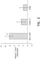
- Fig. 2 is a bar chart indicating the responses of ADHD patients to stimulation of the right prefrontal cortex using, respectively, (a) a deep transcranial magnetic stimulation (dTMS) coil, (b) a figure-eight transcranial magnetic stimulation (TMS) coil, and (c) a sham TMS coil.
- the ADHD patients were identified as suffering from ADHD using standard tests, such as Conners' Adult ADHD Rating Scales.
- the left-most bar of the bar chart of Fig. 2 shows the results of treating a group of 15 ADHD patients using a dTMS coil.
- the patients were stimulated using a coil configured to apply dTMS, for example, as described in US 7,407,478 to Zangen, US 8,608,634 to Zangen, and/or US 2014/0235928 to Zangen.
- 15 daily treatment sessions were applied to each of the patients over a period of three weeks, the treatment being applied over five daily sessions each week.
- 40 stimulation trains were applied to the right prefrontal cortex. Each of the trains had a duration of 2 seconds, and there was a 20 second inter-train interval, between each of the trains.
- the stimulation was applied at a frequency of 18 Hz.
- the dTMS stimulation resulted in an improvement of 8 to the T-score of the patients, the T-scores being measured in accordance with Conners' Adult ADHD Rating Scales.
- the above results had a p-value of less than 0.05.
- the middle bar of the bar chart of Fig. 2 shows the results of treating a group of 11 ADHD patients using a figure-eight stimulation coil.
- the patients were treated using a generally similar treatment protocol to the above-described protocol.
- the stimulation using the figure-eight coil resulted in a lower average improvement to the patients' T-scores than that measured on the patients who were stimulated using a dTMS coil.
- the right-most bar of the bar chart of Fig. 2 shows the results of treating a group of 12 ADHD patients using a sham TMS coil.
- the patients were treated using a generally similar treatment protocol to the above-described protocol.
- the stimulation using the sham coil resulted in a lower average improvement to the patients' T-scores than that measured on the patients who were stimulated using a dTMS coil.
- Fig. 2 The results shown in Fig. 2 indicate that applying dTMS to the pre-frontal cortex may be a suitable treatment for at least some ADHD patients.
- EEG recordings were taken from the patients, before, during and after the first and the last days of treatment.
- EEG recordings were taken (a) during a stop signal task (SST), and (b) following a single TMS pulse applied to the right pre-frontal cortex, using a figure-eight coil.
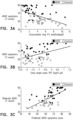
- Figs. 3A-C are graphs showing the correlation between T-scores of ADHD patients and of healthy subjects and respective indicators, in accordance with some applications of the present invention.
- event-related potentials of the ADHD patients were recorded during stop signal tasks.
- event-related potentials of healthy subjects were also recorded during similar stop signal tasks. It was found that both for successful stops and unsuccessful stops, there was a difference between the amplitudes of components of the event-related potentials of the ADHD patients compared to those of the healthy subjects. For example, substantially lower amplitudes of the N200 and P300 components recorded during the stop signal tasks, were evident in the ADHD patients compared to the healthy subjects.
- Fig. 3A is a graph indicating the relationship between the T-scores of both the ADHD patients and the healthy subjects and the P300 amplitude recorded during unsuccessful stop signal tasks performed by the patients/subjects.
- the P300 amplitude was recorded using frontal central and parietal electrodes. As shown, there is a correlation between the T-scores and the P300 amplitudes, the correlation coefficient being - 0.51.
- Fig. 3B is a graph indicating the relationship between the T-scores of both the ADHD patients and the healthy subjects and the TMS-evoked potentials ("TEP"). As shown, there is a correlation between the T-scores and the TMS-evoked potentials, the correlation coefficient being - 0.39. (It is noted that in Fig. 3B , the correlation between the T-scores of both the ADHD patients and the healthy subjects and the TMS-evoked potentials appears to be positive, but this is because the TMS-evoked potentials were negative, and a logarithmic scale was used to measure the TMS-evoked potentials.)
- Fig. 3C is a graph indicating the correlation between the T-scores of both the ADHD patients and the healthy subjects and a predicted ADHD symptoms score, the predicted score being based upon (a) the P300 amplitudes recorded during unsuccessful stop signal tasks performed by the patients/subjects (indicated in Fig. 3A ), and (b) the TMS-evoked potentials of the patients/subjects (indicated in Fig. 3B ), in a multiple regression model. As shown, there is substantial correlation between the T-scores and the ADHD-indicator, the correlation coefficient being 0.61.
- TMS is applied to a subject who is suspected of suffering from ADHD.
- the TMS is applied at least to the subject's right pre-frontal cortex.
- the subject's EEG is detected at a given time interval following the TMS stimulation.
- At least partially in response to a characteristic of the TMS-evoked EEG signal it is determined whether or not the subject suffers from ADHD, and/or an ADHD score of the subject is calculated.
- event-related potentials are measured during stop signal tasks that are performed by the subject.
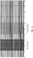
- Fig. 4 shows an intra-treatment EEG recording of a subject, in accordance with some applications of the present invention.
- the recording is from a subject who has ADHD and was recorded while the subject was receiving dTMS in accordance with the stimulation protocol described hereinabove, with reference to Fig. 2 .
- 40 stimulation trains were applied to the subject's right prefrontal cortex.
- Each of the trains had a duration of 2 seconds, and there was a 20 second inter-train interval, between each of the trains.
- EEG measurements were recorded from the subject.
- the EEG recordings from inter-train intervals were sampled over two-second segments.
- the two-second segments were sampled after at least one second had passed from the end of the previous TMS train, in order to reduce the effects of direct artifacts of the dTMS stimulation on the EEG signal.
- Fig. 4 shows an example of such a sampling, a two second segment being shown to be sampled approximately one second after the end of the previous TMS train. (Although the two-second interval shown in Fig.
- TMS using a dTMS coil, a figure-eight coil, or a sham coil
- the patients' intra-treatment EEG signals were recorded on the first, eighth and fifteenth days of the days on which the TMS was applied.
- Two-second interval sections of the inter-treatment EEG signals were sampled, as shown in Fig. 4 , and the samples were spectrally analyzed, such that the powers of respective frequency components within the samples were calculated.
- the patients' T-scores were measured in order to measure the responsiveness of the patients to the TMS treatments.
- the responsiveness of the patients to the treatment was then compared to the power of the respective frequency components of the two-second interval EEG samples as recorded at the first treatment session (i.e., as recorded during the TMS that was applied on the first day of the treatment).
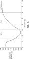
- Fig. 5 is a graph indicating, for the ADHD patients to whom dTMS was applied, the degree of correlation between (a) improvements to patients' T-scores, and (b) the power of respective frequency components of the two-second interval EEG samples as recorded at the FC4 EEG electrode at the first treatment session. As shown, there is a correlation between many frequency components of the two-second interval EEG samples as recorded at the first treatment session and the improvements to the patients' T-scores. It is noted that although the EEG signals from which the samples were taken and spectrally analyzed were recorded at the first treatment session of a three-week course of treatment, the graph shown in Fig. 5 indicates that there is a correlation between the power of certain frequency components of the sample and the responsiveness of the patients to the treatment, as measured after the three-week course of treatment.
- the graph shown in Fig. 5 indicates that an electrophysiological signal of a subject recorded within a given time period after applying TMS to the subject may serve as an indicator of the responsiveness of the subject to treating the subject for a given neuropsychiatric condition using a given therapy. Therefore, for some applications of the present invention computer processor 16 ( Fig. 1 ) drives transcranial magnetic stimulation device 10 to apply one or more pulses (e.g., one or more trains) of transcranial magnetic stimulation to a subject. Within a given time period of applying one of the pulses of transcranial magnetic stimulation to the subject, the computer processor detects an electrophysiological signal of the subject, using the electrophysiological signal detecting electrodes 14.
- pulses e.g., one or more trains
- the computer processor predicts an outcome of treating the subject for a neuropsychiatric condition, using a given therapy. For some applications, the computer processor generates an output on an output device (such as monitor 18) in response to the predicted outcome.
- the EEG signal of a patient suffering from ADHD may be recorded a given time period after applying a TMS or dTMS train to the subject, or during the application of a TMS or dTMS train to the subject. In response thereto, the responsiveness of the patient to using TMS or dTMS to treat the patient for ADHD is predicted.
- the frequency range of approximately 8 Hz (e.g., 8 Hz plus/minus 2 Hz) to approximately 15 Hz (e.g., 15 Hz plus/minus 3 Hz) is described as the alpha band
- the range of approximately 15 Hz (e.g., 15 Hz plus/minus 3 Hz) to approximately 30 Hz (e.g., 30 Hz plus/minus 5 Hz) is described as the beta band
- the frequency range of approximately 30 Hz (e.g., 30 Hz plus/minus 5 Hz) to approximately 100 Hz (e.g., 100 Hz plus/minus 10 Hz) is described as the gamma band.
- These categorizations are indicated upon the graph shown in Fig. 5 .
- the frequency range of approximately 30 Hz (e.g., 30 Hz plus/minus 5 Hz) to approximately 40 Hz (e.g., 40 Hz plus/minus 5 Hz) is further categorized as the low-gamma band.
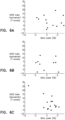
- Figs. 6A-C are graphs showing the relationship between improvements to T-scores of ADHD patients, and the power of the alpha frequency band of an intra-treatment EEG that was recorded at the FC4 EEG electrode on the first day of a treatment, sampled as described hereinabove, for patients that were treated using, respectively, a sham coil ( Fig. 6A ), a figure-eight coil ( Fig. 6B ), and a dTMS coil ( Fig. 6C ).
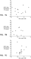
- Figs. 7A-C are graphs showing the relationship between improvements to T-scores of ADHD patients, and the power of the beta frequency band of an intra-treatment EEG that was recorded at the FC4 EEG electrode on the first day of a treatment, sampled as described hereinabove, for patients that were treated using, respectively, a sham coil ( Fig. 7A ), a figure-eight coil ( Fig. 7B ), and a dTMS coil ( Fig. 7C ).
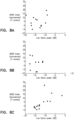
- Figs. 8A-C are graphs showing the relationship between improvements to T-scores of ADHD patients, and the power of the low gamma frequency band of an intra-treatment EEG that was recorded at the FC4 EEG electrode on the first day of a treatment, sampled as described hereinabove, for patients that were treated using, respectively, a sham coil ( Fig. 8A ), a figure-eight coil ( Fig. 8B ), and a dTMS coil ( Fig. 8C ).
- Figs. 9A-C are graphs showing the relationship between (a) improvements to T-scores of ADHD patients, and (b) the power of the low gamma frequency band of an intra-treatment EEG that was recorded at the FC4 EEG electrode on the first day of a treatment, sampled as described hereinabove, and normalized by the power of the alpha frequency band using a decibel scale, for patients that were treated using, respectively, a sham coil ( Fig. 9A ), a figure-eight coil ( Fig. 9B ), and a dTMS coil ( Fig. 9C ).
- computer processor 16 detects an EEG signal of the subject, using EEG electrodes.
- the computer processor calculates the power of a given frequency band within the detected EEG signal.
- the computer processor predicts an outcome of treating the subject for a neuropsychiatric condition, using a given therapy.
- the computer processor generates an output on an output device (such as monitor 18) in response to the predicted outcome.
- the EEG signal of a patient suffering from ADHD may be recorded (e.g., after applying dTMS to the subject).
- the power of a given frequency band (e.g., the alpha band, or the low gamma band) is calculated, and in response thereto, the responsiveness of the patient to using dTMS to treat the patient for ADHD is predicted.
- the powers of two or more frequency bands are combined and/or manipulated using a mathematical operation.
- the power of the given frequency band is normalized by dividing the power of the given frequency band by that of a different frequency band.
- the low gamma frequency band may be normalized by being divided by the power of a different frequency band, such as an alpha frequency band.
- the powers of two or more frequency bands may be combined and/or manipulated using a different mathematical operation.
- computer processor 16 detects an electrophysiological signal (typically, an electroencephalography (EEG) signal) of the subject, using electrodes 14.
- EEG electroencephalography
- activity-related features are identified in the EEG signal, and a brain network activity (BNA) pattern is constructed based on those features.
- BNA brain network activity
- the computer processor predicts an outcome of treating the subject for a neuropsychiatric condition, using a given therapy.
- the computer processor generates an output on an output device (such as a display) in response to the predicted outcome.
- Brain network activity pattern 20 has a plurality of nodes 22, each representing an activity-related feature.
- a node can represent a particular frequency band (optionally two or more particular frequency bands) at a particular location and within a particular time-window or latency range, optionally with a particular range of amplitudes.
- the brain network activity pattern is a represented as a graph having nodes and edges.
- the brain network activity pattern includes a plurality of discrete nodes, wherein information pertaining to features of the data is represented only by the nodes and information pertaining to relationships between the features is represented only by the edges.
- Fig. 10A illustrates brain network activity pattern 20 within a template 26 of a scalp, demonstrating the relationship between the locations of the nodes and lobes of the brain (frontal 28, central 30, parietal 32, occipital 34 and temporal 36).
- the nodes in the brain network activity pattern can be labeled by their various characteristics.
- a color coding or shape coding visualization technique can also be employed, if desired. For example, nodes corresponding to a particular frequency band can be displayed using one color or shape and nodes corresponding to another frequency band can be displayed using another color or shape.
- red nodes may be used to correspond to Delta waves and green nodes to correspond to Theta waves.
- "red" nodes are illustrated with solid black circles, and "green” nodes are illustrated with a solid black circle surrounded by an outer circle (of which there are three in Fig. 10A ).
- Brain network activity pattern 20 can describe brain activity of a single subject or a group or sub-group of subjects.
- a brain network activity pattern that describes the brain activity of a single subject is referred to herein as a subject-specific brain network activity pattern, and a brain network activity pattern that describes the brain activity of a group or sub-group of subjects is referred to herein as a group brain network activity pattern.
- brain network activity pattern 20 is a subject-specific brain network activity pattern, only vectors extracted from data of a given subject are used to construct the brain network activity pattern for that subject.
- each node corresponds to a point in the multidimensional space and therefore represents an activity event in the brain.
- brain network activity pattern 20 is a group brain network activity pattern, some nodes can correspond to a cluster of points in the multidimensional space, and the pattern therefore represents an activity event which is prevalent in the group or sub-group of subjects.
- the number of nodes (referred to herein as the "order") and/or edges (referred to herein as the "size") in a group brain network activity pattern is typically, but not necessarily, larger than the order and/or size of a subject-specific brain network activity pattern.
- each of the clusters referred to herein as clusters A and B, is represented by a node in the group brain network activity pattern.
- the two clusters A and B are identified as activity-related features since there are some individual points within these clusters that pass the criteria for such a relationship (the pairs of Subject Nos. 4 and 5, in the present example, as will be explained in further detail below).
- the nodes corresponding to clusters A and B are connected by an edge.
- a simplified illustration of the resulting group brain network activity pattern is illustrated in Fig. 10C .
- a subject-specific brain network activity pattern is typically constructed by comparing the features and relations among features of the EEG signal collected from the subject to the features and relations among features of reference data, which, for some applications, correspond to EEG signals of the group. For such applications, points and relationships among points associated with the subject's signal are compared to clusters and relationships among clusters associated with the group's data.
- a "segment" corresponds to a different subject in a group or sub-group of subjects.
- Cluster A does not include a contribution from Subject No. 3
- cluster B does not include a contribution from Subject No. 6, since for these subjects the respective points fail to pass the time-window criterion.
- both locations A and B are represented as nodes in the subject-specific brain network activity patterns constructed for any of Subject Nos. 1, 2, 4 and 5.
- the corresponding nodes are connected by an edge.
- a simplified illustration of a subject-specific brain network activity pattern for such a case is shown in Fig. 10D .
- the subject-specific brain network activity pattern of Fig. 10D is similar to the group brain network activity pattern of Fig. 10C .
- the order and/or size of the group brain network activity pattern is, as stated, typically larger than the order and/or size of the subject-specific brain network activity pattern.
- An additional difference between the subject-specific and group brain network activity patterns can be manifested by the degree of relation between the activity-related features represented by the edges, as further detailed hereinbelow.
- Fig. 10E A simplified illustration of a subject-specific brain network activity pattern for such cases is shown in Fig. 10E .
- a subject-specific brain network activity pattern can be constructed only from the EEG signals obtained from a single subject.
- vectors of waveform characteristics are extracted separately for time-separated TMS stimuli, to define clusters of points where each point within the cluster corresponds to a response to a stimulus applied at a different time, as further detailed hereinabove.
- the procedure for constructing subject-specific brain network activity patterns in such applications is typically generally similar to the procedure for constructing a group brain network activity pattern described above. However, since all signals are collected from a single subject, the brain network activity pattern is subject-specific.
- a subject-specific brain network activity pattern is generated that is of one of two types: a first type that describes the association of the particular subject to a group or sub-group of subjects, which is a manifestation of a group brain network activity pattern for the specific subject, and a second type that describes the data of the particular subject without associating the subject to a group or sub-group of subjects.
- the former type of brain network activity pattern is referred to herein as an associated subject-specific brain network activity pattern
- the latter type of brain network activity pattern is referred to herein as an unassociated subject-specific brain network activity pattern.
- the analysis is typically performed on a set of evoked responses. Typically, the data is then averaged and a single vector of the data is generated.
- the data of each subject of the group is typically averaged and thereafter turned into vectors of the data.
- an unassociated subject-specific brain network activity pattern is typically unique for a particular subject (at the time the subject-specific brain network activity pattern is constructed)
- the same subject may be characterized by more than one associated subject-specific brain network activity patterns, since a subject may have different associations to different groups.
- a subject may have different associations to different groups.
- a group of healthy subjects and a group of non-healthy subjects all suffering from the same brain disorder For example a subject Y, who may or may not belong to one of those groups.
- One or more of several subject-specific brain network activity patterns for subject Y may be generated, in accordance with respective applications of the present invention.
- a first brain network activity pattern is an unassociated subject-specific brain network activity pattern, which, as stated, is generally unique for this subject, since it is constructed from data collected only from subject Y.
- a second brain network activity pattern is an associated subject-specific brain network activity pattern constructed in terms of the relationship between the data of subject Y to the data of the healthy group.
- a third brain network activity pattern is an associated subject-specific brain network activity pattern constructed in terms of the relation between the data of subject Y to the data of the non-healthy group. Each of these brain network activity patterns is useful for assessing the condition of subject Y.
- the first brain network activity pattern can be useful, for example, for monitoring changes in the brain function of the subject over time (e.g., monitoring brain plasticity or the like) since it allows comparing the brain network activity pattern to a previously constructed unassociated subject-specific brain network activity pattern.
- the second and third brain network activity patterns can be useful for determining the level of association between subject Y and the respective groups, thereby determining the likelihood of brain disorder for the subject.
- the reference data used for constructing the subject-specific brain network activity pattern correspond to historic data previously acquired from the same subject. Such applications are performed in a generally similar manner to the applications described above regarding the generation of an associated subject-specific brain network activity pattern, except that the brain network activity pattern is associated with the history of the same subject instead of being associated with a group of subjects.
- reference data corresponding to data acquired from the same subject at some later time are used. Such applications allow investigating whether data acquired at an early time evolve into the data acquired at the later time.
- a particular and non-limiting example is the case of several treatment sessions, e.g., N sessions, for the same subject.
- Data acquired in the first several treatment sessions can be used as reference data for constructing a first associated subject-specific brain network activity pattern corresponding to mid sessions (e.g., from session k2> k1 to session k3>k2), and data acquired in the last several treatment sessions (e.g., from session k4 to session N) can be used as reference data for constructing a second associated subject-specific brain network activity pattern corresponding to the aforementioned mid sessions, where 1 ⁇ k1 ⁇ k2 ⁇ k3 ⁇ k4.
- Two such associated subject-specific brain network activity patterns for the same subject can be used for determining data evolution from the early stages of the treatment to the late stages of the treatment.
- TMS pulses are applied to each of a group of subjects over a multi-session treatment period.
- a reference group brain network activity pattern is constructed from EEG signals obtained from the subjects of the group on the first session (e.g., the first day, when each session occurs on a different day), and typically based on a single pulse TEP.
- the inventors of the present applications have found that a single pulse TEP during the first session has a marginal effect on the brain, so that an EEG signal obtained after such pulse can be considered as corresponding to an untreated subject.
- the reference group brain network activity pattern can be used as a basis for constructing, for one or more of the subjects in the group, an associated subject-specific brain network activity pattern describing the association or lack of association of the particular subject to the group.
- Such an associated subject-specific brain network activity pattern can be constructed for the particular subject also in one or more subsequent sessions, thereby showing the effect of the treatment relative to the effect of the single pulse TEP during the first session.
- a connectivity weight is assigned to each pair of nodes in the brain network activity pattern (or, equivalently, to each edge in the brain network activity) pattern, thereby providing a weighted brain network activity pattern.
- the connectivity weight is represented in Figs.10A , 10C and 10D by the thickness of the edges connecting two nodes. For example, thicker edges can correspond to higher weights and thinner edges can correspond to lower weights.
- the connectivity weight includes a weight index calculated based on at least one of the following cluster properties: (i) the number of subjects participating in the corresponding cluster pair, wherein greater weights are assigned for larger number of subjects; (ii) the difference between the number of subjects in each cluster of the pair (referred to as the "differentiation level" of the pair), wherein greater weights are assigned for lower differentiation levels; (iii) the width of the time windows associated with each of the corresponding clusters (see, e.g., ⁇ t A and ⁇ t B in FIG. 10B ), wherein greater weights are assigned for narrower windows; (iv) the latency difference between the two clusters (see, e.g., ⁇ t AB in FIG.
- the connectivity weight typically equals the weight index as calculated based on the cluster properties.
- the connectivity weight of a pair of nodes is preferably assigned based on the weight index (denoted WI ), as well as one or more subject-specific and pair-specific quantities (denoted SI ). Representative examples of such quantities are provided below.
- a pair of nodes of the associated subject-specific brain network activity pattern is assigned with a connectivity weight which is calculated by combining WI with SI.
- the connectivity weight of a pair in the associated subject-specific brain network activity pattern can be given by WI ⁇ SI.
- the pair when a plurality of quantities (e.g., N quantities) are calculated for a given pair of nodes, the pair can be assigned with more than one connectivity weights, e.g., WI ⁇ SI 1 , WI ⁇ SI 2 , ..., WI ⁇ SI N , wherein SI 1 , SI 2 , ..., SI N , are N calculated quantities.
- all connectivity weights of a given pair are combined, e.g., by averaging, multiplying and the like.
- the quantity SI can be, for example, a statistical score characterizing the relationship between the subject-specific pair and the corresponding clusters.
- the statistical score can be of any type, including, without limitation, deviation from average, absolute deviation, standard-score and the like.
- the relationship for which the statistical score is calculated can pertain to one or more properties used for calculating the weight index, including, without limitation, latency, latency difference, amplitude, frequency and the like.
- a statistical score pertaining to latency or latency difference is referred to herein as a synchronization score and denoted SIs.
- a synchronization score according to some applications of the present invention is obtained by calculating a statistical score for (i) the latency of the point as obtained for the subject (e.g., t(i) A and t (i) B , in the above example) relative to the group-average latency of the corresponding cluster, and/or (ii) the latency difference between two points as obtained for the subject (e.g., ⁇ t ( i ) AB ), relative to the group-average latency difference between the two corresponding clusters.
- an amplitude score is obtained by calculating a statistical score for the amplitude, as obtained for the subject, relative to the group-average amplitude of the corresponding cluster.
- a statistical score pertaining to frequency is referred to herein as a frequency score and denoted SIf.
- a frequency score according to some applications of the present invention is obtained by calculating a statistical score for the frequency, as obtained for the subject, relative to the group-average frequency of the corresponding cluster.
- a statistical score pertaining to the location is referred to herein as a location score and denoted SIl. Using such a score is typically useful for applications in which a continuous coordinate system is employed, as further detailed hereinabove.
- a location score according to some applications of the present invention is obtained by calculating a statistical score for the location, as obtained for the subject, relative to the group-average location of the corresponding cluster.
- SIs a synchronization score
- the calculation is typically based on the discrete time points matching the spatiotemporal constraints set by the electrode pair ( Time subj ), if such exist.
- the times of these points are compared to the mean and standard deviation of the times of the discrete points participating in the group pattern ( Time pat ), for each region to provide a regional synchronization score SIs r .
- the synchronization score SIs can then be calculated, for example, by averaging the regional synchronization scores of the two regions in the pair.
- the quantity SI includes a correlation value between recorded activities.
- the correlation value describes correlation between the activities recorded for the specific subject at the two locations associated with the pair, and, for some applications, the correlation value describes correlation between the activities recorded for the specific subject at any of the locations associated with the pair and the group activities as recorded at the same location.
- the correlation value describes causality relations between activities.
- the connectivity weights assigned over the brain network activity pattern is calculated as a continuous variable (e.g., using a function having a continuous range), or as a discrete variable (e.g., using a function having a discrete range, or using a lookup table).
- connectivity weights can have more than two possible values.
- the weighted brain network activity pattern has at least three, or at least four, or at least five, or at least six edges, each of which being assigned with a different connectivity weight.
- the brain network activity pattern is constructed it is transmitted to a display device such as monitor 18, or a printer (not shown). Alternatively or additionally, the brain network activity pattern is transmitted to a computer-readable medium.
- the subject-specific brain network activity pattern of a particular subject is compared to a previously constructed brain network activity pattern, e.g., the reference group brain network activity pattern constructed from EEG signals obtained from the subjects of the group on the first session based on a single pulse TMS-evoked potential (TEP).
- a score is assigned to the subject-specific brain network activity pattern.
- a score can be, for example, a brain network activity pattern similarity score S.
- the brain network activity pattern similarity S between the two brain network activity patterns is typically calculated based on the values of the connectivity weights of the subject-specific brain network activity pattern.
- the brain network activity pattern similarity may be obtained by averaging the connectivity weights over the subject-specific brain network activity pattern.
- the averaging is typically performed over the brain network activity pattern separately for each type of connectivity weight.
- one or more of the averages are combined (e.g., summed, multiplied, averaged, etc.) to provide a combined brain network activity pattern similarity.
- a representative of the averages e.g., the largest is defined as the brain network activity pattern similarity.
- the brain network activity pattern similarity is used as a score, which describes, quantitatively, the membership level of the subject to the group.
- a score is referred to as a brain network activity score.
- a group brain network activity pattern constructed from EEG signals obtained on the first session based on a single pulse TEP it describes the membership level (or lack of membership) of the subject to a group that is generally considered as a group of untreated subjects.
- Such applications are typically useful for determining the evolved effect of the TMS over the sessions for the subject.
- the brain network activity score is expressed as a continuous or discrete variable.
- the similarity is a non-binary number.
- the degree by which the two brain network activity patterns are similar or dissimilar is calculated.
- the similarity can be expressed as percentage, as a non-integer number between 0 and 1 (e.g., 0 corresponding to complete dissimilarity and 1 corresponding to comparison between a brain network activity pattern and itself), and the like.
- At least one brain network activity pattern similarity is calculated, the similarity describing the similarity between the brain network activity pattern and a previously annotated brain network activity pattern.
- dTMS treatment was administered in 20 stimulation sessions over a period of 4 weeks.
- the stimulation was performed over the left prefrontal cortex, at 10 Hz, and over the right prefrontal cortex, at 1 Hz.
- the 10 Hz stimulation was delivered using 2 second trains of 20 pulses with an inter train interval of 15 seconds, during which the 1 Hz stimulation was applied, EEG was recorded prior to start of treatment, then every 5 sessions (i.e., sessions 1, 6, and 11), and then on one of the days during the week after the last session.
- Each dTMS treatment included stimulation of 25.5 minutes of dual channel dTMS treatment.
- results described in this example were obtained from thirty healthy subjects and 24 major depressive disorder patients.
- Fig. 11A is a graph indicating, for major depressive disorder patients to whom dTMS was applied, the degree of correlation between (a) improvements to patients' Hamilton depression rating scale (“HDRS") after four weeks of TMS treatment versus (b) Long Interval Cortical Inhibition TMS-evoked potentials (LICI-TEP) deflection values corresponding to the difference between the single pulse and the second pulse in a pair that was recorded on the first day of a treatment prior to initiation of treatment, in accordance with some applications of the present invention.
- FIG. 11A are negativity deflection values of the difference waveform between the single pulse TEP and TEP of the second pulse in a pair (DIFF) recorded 60-140 after the TMS pulse at electrode F3, at the first treatment session prior to initiation of treatment.
- DIFF difference waveform between the single pulse TEP and TEP of the second pulse in a pair
- a 21-item questionnaire (HDRS-21) was used. The correlation coefficient is 0.473, the corresponding probability is 0.03.
- Fig. 11B is a graph indicating, for major depressive disorder patients to whom dTMS was applied, the degree of correlation between (a) improvements to patients' HDRS after four weeks of dTMS treatment versus (b) LICI-TEP deflection values generated by a single pulse that was recorded on the first day of a treatment prior to initiation of treatment, in accordance with some applications of the present invention.
- the deflection values that are plotted on the x-axis of Fig. 11B are single pulse TEP deflection values (area) recorded 140-300 ms after the TMS pulse at electrode FC6, at the first treatment session prior to initiation of treatment.
- a 21-item questionnaire (HDRS-21) was used.
- the correlation coefficient is 0.402, and the corresponding probability is 0.07.
- FIGs. 12A and 12B are graphs indicating, for major depressive disorder patients to whom dTMS was applied, the degree of correlation between (a) improvements to patients' HDRS measure after four weeks of TMS treatment, versus (b) the power of respective frequency components of thirteen-second interval EEG samples, as recorded at electrode location F7, at the first treatment session prior to initiation of treatment, FIG. 12A corresponding to a high-frequency wave (20-40 Hz) at electrode location F7, and FIG. 12B corresponding to a Low Gamma wave (30-40 Hz) at electrode location F7, in accordance with some applications of the present invention.
- Respective group brain network activity patterns were constructed from EEG signals acquired after TMS pulses (single, paired) were applied to both the healthy subjects and the major depressive disorder patients.
- subject-specific brain network activity patterns were constructed, and brain network activity similarity scores of the subject-specific brain network activity patterns were calculated.
- Fig. 13A is a graph showing the relationship between (a) the percentage improvement to major depressive disorder patients' HDRS after three weeks of treatment versus (b) the patients' brain network activity similarity scores generated by single pulse TEP as recorded prior to treatment commencing, and as compared to the brain network activity of healthy subjects, in accordance with some applications of the present invention
- the correlation coefficient is 0.775268, the corresponding probability is 0.0051 and the number of subjects is 11.
- a 21-item questionnaire (HDRS-21) was used.
- the graph demonstrates that patients that obtained high brain network activity similarity scores with respect to the healthy subjects, showed the greatest benefit from the dTMS treatment, and that the brain network activity score successfully predicts the responsiveness of major depressive disorder patients to dTMS treatment. Similar correlations were obtained using a reference group brain network activity pattern constructed from EEG signals obtained after the second pulse in a paired-pulse TMS stimulation, demonstrating that predicting TMS treatment responsiveness based brain network activity is not limited to just one type of TMS pulse.
- Fig. 13B is a graph showing the relationship between (a) similarity scores of the brain network activity of major depressive disorder patients generated by single pulse TEP, as compared to the brain network activity of major depressive disorder patients, and (b) the patients' HDRS, in accordance with some applications of the present invention.
- the correlation coefficient of the data shown in Fig. 13B is 0.853554, the corresponding probability is 0.0017.
- a 17-item questionnaire (HDRS-17) was used.
- the similarity scores were generated based upon brain network activity patterns of the patients that were generated after three weeks of treatment, and the HDRS of the patients were also measured at the same point in time.
- the relationship shown in Fig. 13B at a given moment in time, there is a correlation between the similarity scores of the brain network activity of the patients, as compared to the brain network activity of major depressive disorder patients, and the patients' HDRS.
- the data shown in Fig. 13B indicate that the brain network activity of patients suffering from a given neuropsychiatric condition can be used to measure the severity of their condition as an alternative to, or in addition to, their condition being graded by used of standard models. For example, based on the data shown in Fig.
- the patients' brain network activity can be measured and the patients can be graded based upon their brain network activity (e.g., by comparing their brain network activity to that of a group of healthy subjects, or to that of a group of unhealthy subjects).
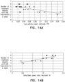
- Figs. 14A and 14B are graphs showing the relationship between (a) the time after initiating dTMS treatment of major depressive disorder patients to respective percentage improvements from pre-treatment baseline in the patients' HDRS, and (b) the power of respective frequency components of the thirteen-second interval EEG samples as recorded at respective EEG electrodes prior to treatment commencing, in accordance with some applications of the present invention.
- Fig. 14A plots the number of EEG visits until the patients reached a 40 percent improvement in their HDRS relative to their pre-treatment HDRS, against the low gamma power (30-40 Hz) recorded at electrode FT8 in response to a TMS pulse that was applied on the first day of treatment, prior to commencement of treatment.
- Fig. 14B plots the number of EEG until the patients reached a 50 percent improvement in their HDRS relative to their pre-treatment HDRS, against the delta (1-4 Hz) to beta (12-30 Hz) power ratio as recorded at electrode T8 in response to a TMS pulse that was applied on the first day of treatment, prior to commencement of treatment.
- the correlation between the time taken to the 50 percent HDRS improvement relative to the delta-to-beta power ratio was positive, with a correlation value of 0.83, indicating that patients with lower right lateral delta-to-beta power ratio at the prior to TMS treatment showed faster response to the treatment.
- the correlations demonstrated in both Fig. 14A and Fig. 14B are statistically significant (p ⁇ 0.001).
- the EEG power spectral density function obtained prior to treatment commencing is highly correlated with the time to response to treatment, as measured using HDRS. Therefore, in accordance with some applications of the present invention, even prior to treatment of a subject commencing, one or more pulses of transcranial magnetic stimulation are applied to the subject. Within a given time period of applying one of the one or more pulses of transcranial magnetic stimulation to the subject, an electrophysiological signal of the subject (e.g., the subject's EEG) is detected.
- EEG electrophysiological signal of the subject
- the time that it will take to treat (or at least partially treat) the subject for a neuropsychiatric condition, using a given therapy is predicted.
- a rate of the improvement in the subject's condition, in response to the treatment is predicted.
- the power density of specific frequency bands is measured, and the prediction is made responsively thereto.
- a relationship e.g., a ratio between the power densities of two or more frequency bands is detected, and the prediction is made responsively thereto.
- FIGs 15A, 15B, and 15C are flowcharts showing steps that are performed by a computer processor, in accordance with some applications of the present invention.
- the computer processor drives TMS device 10 ( Fig. 1 ) to apply one or more TMS pulses to a subject suffering from a given neuropsychiatric condition.
- the computer processor detects an electrophysiological signal of the subject signal subsequent to the one or more pulses being applied.
- the subject's EEG may be detected using electrodes 14 (shown in Fig. 1 ).
- the EEG recorded at one or more given electrodes is detected.
- the computer processor predicts the outcome of treating the subject using a given treatment, responsively to the detected electrophysiological signal. In accordance with the data shown in Fig.
- the computer processor predicts the time that it will take until the subject's condition improves by a given amount, and/or predicts a rate of the improvement in the subject's condition, in response to the given treatment being applied to the subject.
- the flowchart shown in Fig. 15B is generally similar to that of Fig. 15A . However, the flowchart shown in 15B, includes additional steps 46 and 48, in accordance with some applications of the present invention.
- the power density of one or more given frequency bands within the detected electrophysiological signal is measured, as indicated in step 46.
- step 48 (which is optional, as indicated by the dashed box)
- the power densities of two or more frequency bands are combined.
- a relationship e.g., a ratio
- step 44 in which the subject's response to treatment using a given therapy is predicted
- step 48 is performed in response to step 46, and/or step 48.
- step 50 the subject's brain network activity pattern is constructed based on the detected electrophysiological signal, e.g., using techniques described hereinabove.
- step 52 which is optional, as indicated by the dashed box
- a similarity score is calculated for the subject's brain network activity patter, e.g., by comparing the subject's brain network activity pattern to a group pattern, such as a healthy subject group pattern, or the pattern of a group suffering from a given neuropsychiatric condition.
- step 44 in which the subject's response to treatment using a given therapy is predicted is performed in response to step 50, and/or step 52.
- the scope of the present invention includes using an electrophysiological response to a single pulse of TMS for predicting a subject's response to a treatment, in accordance with the general techniques described herein, mutatis mutandis.
- the scope of the present invention includes using an electrophysiological response that is measured at various time points following a given transcranial magnetic stimulation pulse for predicting a subject's response to a treatment, in accordance with the general techniques described herein, mutatis mutandis.
- EEG recordings may be measured at any of the following times:
- a plurality of electrophysiological measurements that were recorded at respective times with respect to application of TMS are averaged (or otherwise combined) over several minutes or over a full TMS session, and the subject's response to a treatment is predicted responsively thereto, in accordance with the general techniques described herein, mutatis mutandis.
- the scope of the present invention includes using any form of TMS configuration (e.g., using dTMS coils, or TMS using figure-eight coils) and any form of stimulation protocol (e.g. including single pulses, paired pulses, single trains and multiple trains), and predicting the responsiveness of the patient to various kinds of treatment, including TMS treatment, dTMS treatment, pharmacological treatment, behavioral or psychotherapy treatment, deep brain stimulation (DBS) treatment, electroconvulsive therapy (ECT) treatment and other treatments, based upon a component of an electrophysiological signal of the patient (e.g., the patient's EEG) recorded during or subsequent to TMS being applied to the patient.
- TMS e.g., using dTMS coils, or TMS using figure-eight coils
- stimulation protocol e.g. including single pulses, paired pulses, single trains and multiple trains
- ECT electroconvulsive therapy
- the analysis of a component of the patient's electrophysiological signal recorded subsequent to the application of a TMS pulse (or train, or trains of pulses) is combined with the patient's electrophysiological signal during a certain task, and the combined neuromarker (e.g. a ratio or any other mathematical combination) is used as a predictor for response to treatment.
- electrophysiological recordings as described in the present invention may be used for diagnosis, for disease characterization, for assessment of disease severity and/or for discrimination between healthy subjects and subjects suffering from a neuropsychiatric disorder.
- the inventors of the present application hypothesize that similar effects to the above-described effects which were observed for ADHD patients and major depressive disorder patients would be evident for patients suffering from other conditions, such as depression and other neuropsychiatric disorders such as bipolar disorder, autism, post-traumatic stress disorder (PTSD), addictive behaviors (including smoking, overeating and drug addiction), schizophrenia, Parkinson's disease, Alzheimer's disease, obsessive compulsive disorder (OCD), epilepsy, and others.
- the disclosed device can be applied to patients suffering from any one of the aforementioned conditions, mutatis mutandis.
- a computer-usable or computer-readable medium can be any apparatus that can comprise, store, communicate, propagate, or transport the program for use by or in connection with the instruction execution system, apparatus, or device.
- the medium can be an electronic, magnetic, optical, electromagnetic, infrared, or semiconductor system (or apparatus or device) or a propagation medium.
- the computer-usable or computer readable medium is a non-transitory computer-usable or computer readable medium.
- Examples of a computer-readable medium include a semiconductor or solid-state memory, magnetic tape, a removable computer diskette, a random-access memory (RAM), a read-only memory (ROM), a rigid magnetic disk and an optical disk.
- Current examples of optical disks include compact disk-read only memory (CD-ROM), compact disk-read/write (CD-R/W) and DVD. For some applications, cloud storage is used.
- a data processing system suitable for storing and/or executing program code will include at least one processor coupled directly or indirectly to memory elements through a system bus.
- the memory elements can include local memory employed during actual execution of the program code, bulk storage, and cache memories which provide temporary storage of at least some program code in order to reduce the number of times code must be retrieved from bulk storage during execution.
- the system can read the inventive instructions on the program storage devices and follow these instructions to execute the methodology of the embodiments of the invention.
- Network adapters may be coupled to the processor to enable the processor to become coupled to other processors or remote printers or storage devices through intervening private or public networks.
- Modems, cable modem and Ethernet cards are just a few of the currently available types of network adapters.
- Computer program code for carrying out operations of the present invention may be written in any combination of one or more programming languages, including an object-oriented programming language such as Java, Smalltalk, C++ or the like and conventional procedural programming languages, such as the C programming language or similar programming languages.
- object-oriented programming language such as Java, Smalltalk, C++ or the like
- conventional procedural programming languages such as the C programming language or similar programming languages.
- the computer program instructions may also be loaded onto a computer or other programmable data processing apparatus to cause a series of operational steps to be performed on the computer or other programmable apparatus to produce a computer implemented process such that the instructions which execute on the computer or other programmable apparatus provide processes for implementing the functions/acts specified in the algorithms described in the present application.
- Computer processors described herein are typically hardware devices programmed with computer program instructions to produce a special purpose computer. For example, when programmed to perform the algorithms described herein, the computer processor typically acts as a special purpose treatment-outcome-prediction computer processor. Typically, the operations described herein that are performed by computer processors transform the physical state of a memory, which is a real physical article, to have a different magnetic polarity, electrical charge, or the like depending on the technology of the memory that is used.
Landscapes
- Health & Medical Sciences (AREA)
- Life Sciences & Earth Sciences (AREA)
- Engineering & Computer Science (AREA)
- Biomedical Technology (AREA)
- Public Health (AREA)
- General Health & Medical Sciences (AREA)
- Veterinary Medicine (AREA)
- Animal Behavior & Ethology (AREA)
- Medical Informatics (AREA)
- Heart & Thoracic Surgery (AREA)
- Biophysics (AREA)
- Pathology (AREA)
- Molecular Biology (AREA)
- Surgery (AREA)
- Physics & Mathematics (AREA)
- Psychiatry (AREA)
- Neurology (AREA)
- Psychology (AREA)
- Developmental Disabilities (AREA)
- Radiology & Medical Imaging (AREA)
- Nuclear Medicine, Radiotherapy & Molecular Imaging (AREA)
- Hospice & Palliative Care (AREA)
- Physiology (AREA)
- Child & Adolescent Psychology (AREA)
- Social Psychology (AREA)
- Educational Technology (AREA)
- Signal Processing (AREA)
- Computer Vision & Pattern Recognition (AREA)
- Artificial Intelligence (AREA)
- Neurosurgery (AREA)
- Computer Networks & Wireless Communication (AREA)
- Databases & Information Systems (AREA)
- Epidemiology (AREA)
- Primary Health Care (AREA)
- Data Mining & Analysis (AREA)
- Magnetic Treatment Devices (AREA)
- Measurement And Recording Of Electrical Phenomena And Electrical Characteristics Of The Living Body (AREA)
- Medicines Containing Material From Animals Or Micro-Organisms (AREA)
Applications Claiming Priority (2)
| Application Number | Priority Date | Filing Date | Title |
|---|---|---|---|
| US201662412598P | 2016-10-25 | 2016-10-25 | |
| PCT/IL2017/051163 WO2018078619A1 (en) | 2016-10-25 | 2017-10-25 | Apparatus and methods for predicting therapy outcome |
Publications (2)
| Publication Number | Publication Date |
|---|---|
| EP3532162A1 EP3532162A1 (en) | 2019-09-04 |
| EP3532162B1 true EP3532162B1 (en) | 2024-07-24 |
Family
ID=60262966
Family Applications (1)
| Application Number | Title | Priority Date | Filing Date |
|---|---|---|---|
| EP17794429.5A Active EP3532162B1 (en) | 2016-10-25 | 2017-10-25 | Apparatus for predicting therapy outcome |
Country Status (8)
| Country | Link |
|---|---|
| US (1) | US11400289B2 (enExample) |
| EP (1) | EP3532162B1 (enExample) |
| JP (1) | JP7048598B2 (enExample) |
| CN (1) | CN110114115B (enExample) |
| AU (1) | AU2017349924B2 (enExample) |
| CA (1) | CA3041605A1 (enExample) |
| IL (1) | IL266176B (enExample) |
| WO (1) | WO2018078619A1 (enExample) |
Families Citing this family (47)
| Publication number | Priority date | Publication date | Assignee | Title |
|---|---|---|---|---|
| EP2670299A4 (en) | 2011-02-03 | 2017-08-09 | The Medical Research, Infrastructure, And Health Services Fund Of The Tel Aviv Medical Center | Method and system for use in monitoring neural activity in a subject's brain |
| US9782585B2 (en) | 2013-08-27 | 2017-10-10 | Halo Neuro, Inc. | Method and system for providing electrical stimulation to a user |
| EP3038700B1 (en) | 2013-08-27 | 2020-03-11 | Halo Neuro, Inc. | Method and system for providing electrical stimulation to a user |
| US10695575B1 (en) | 2016-05-10 | 2020-06-30 | Btl Medical Technologies S.R.O. | Aesthetic method of biological structure treatment by magnetic field |
| US20180001107A1 (en) | 2016-07-01 | 2018-01-04 | Btl Holdings Limited | Aesthetic method of biological structure treatment by magnetic field |
| US11464993B2 (en) | 2016-05-03 | 2022-10-11 | Btl Healthcare Technologies A.S. | Device including RF source of energy and vacuum system |
| US11247039B2 (en) | 2016-05-03 | 2022-02-15 | Btl Healthcare Technologies A.S. | Device including RF source of energy and vacuum system |
| US11534619B2 (en) | 2016-05-10 | 2022-12-27 | Btl Medical Solutions A.S. | Aesthetic method of biological structure treatment by magnetic field |
| US10583287B2 (en) | 2016-05-23 | 2020-03-10 | Btl Medical Technologies S.R.O. | Systems and methods for tissue treatment |
| US10556122B1 (en) | 2016-07-01 | 2020-02-11 | Btl Medical Technologies S.R.O. | Aesthetic method of biological structure treatment by magnetic field |
| US11141219B1 (en) | 2016-08-16 | 2021-10-12 | BTL Healthcare Technologies, a.s. | Self-operating belt |
| CN117462844A (zh) | 2017-02-02 | 2024-01-30 | 福禄神经学公司 | 用于经颅直流电刺激tdcs的头戴设备和包括头戴设备的系统 |
| WO2018182534A1 (en) * | 2017-03-31 | 2018-10-04 | Agency For Science, Technology And Research | A computer system for acquiring a control command |
| US10507324B2 (en) | 2017-11-17 | 2019-12-17 | Halo Neuro, Inc. | System and method for individualizing modulation |
| CN108742607A (zh) * | 2018-06-29 | 2018-11-06 | 南阳市中心医院 | 一种神经内科介入治疗装置 |
| EP3952984B1 (en) | 2019-04-11 | 2024-09-04 | BTL Medical Solutions a.s. | Devices for aesthetic treatment of biological structures by radiofrequency and magnetic energy |
| US12558146B2 (en) | 2019-04-11 | 2026-02-24 | Btl Medical Solutions A.S. | Methods and devices for aesthetic treatment of biological structures by radiofrequency and magnetic energy |
| US12156689B2 (en) | 2019-04-11 | 2024-12-03 | Btl Medical Solutions A.S. | Methods and devices for aesthetic treatment of biological structures by radiofrequency and magnetic energy |
| CN110537929B (zh) * | 2019-08-23 | 2022-11-04 | 杭州曼安智能科技有限公司 | 一种基于ssvep的注意力测评方法、训练方法以及脑机接口 |
| CN110840411B (zh) * | 2019-12-06 | 2022-03-11 | 深圳市德力凯医疗设备股份有限公司 | 一种麻醉深度的测量装置、存储介质及电子设备 |
| US12343157B2 (en) | 2020-04-14 | 2025-07-01 | Neurotype Inc. | Assessing motivated attention with cue reactivity |
| US11878167B2 (en) | 2020-05-04 | 2024-01-23 | Btl Healthcare Technologies A.S. | Device and method for unattended treatment of a patient |
| JP2023515722A (ja) | 2020-05-04 | 2023-04-13 | ビーティーエル ヘルスケア テクノロジーズ エー.エス. | 患者の非アテンド式治療のためのデバイスおよび方法 |
| US12611545B2 (en) | 2020-05-04 | 2026-04-28 | Btl Healthcare Technologies A.S. | Device and method for unattended treatment of a patient |
| CN113545790B (zh) * | 2020-07-21 | 2022-04-26 | 浙江大学 | 一种磁兼容神经探针的制备方法 |
| WO2022056652A1 (zh) * | 2020-09-15 | 2022-03-24 | 洪硕宏 | 评估跨颅磁刺激对忧郁症患者是否有效的辅助判断装置 |
| CN114259239A (zh) * | 2020-09-15 | 2022-04-01 | 洪硕宏 | 评估跨颅磁刺激对忧郁症患者是否有效的辅助判断装置 |
| US11571541B2 (en) | 2020-10-27 | 2023-02-07 | David Richardson Hubbard, JR. | Apparatus and methods of transcranial stimulation to adjust sensory cortical dendritic spine neck membrane potentials for altering consciousness |
| EP4292540A4 (en) * | 2021-02-12 | 2025-01-22 | Keio University | SYMPTOM ASSESSMENT DEVICE AND SYMPTOM ASSESSMENT PROGRAM |
| AU2022306382A1 (en) * | 2021-07-06 | 2024-02-08 | Sinaptica Therapeutics, Inc. | Systems and methods for providing personalized targeted non-invasive stimulation to a brain network |
| CN117940188A (zh) * | 2021-07-06 | 2024-04-26 | 西纳蒂卡治疗股份有限公司 | 用于向脑网络提供个性化靶向非侵入性刺激的系统和方法 |
| CN113545792B (zh) * | 2021-07-20 | 2024-06-18 | 深圳市人民医院 | 一种基于tms-eeg的神经生物标记物的检测方法 |
| CN113694374B (zh) * | 2021-08-31 | 2026-04-21 | 上海市精神卫生中心(上海市心理咨询培训中心) | 基于EEG预测tDCS治疗强迫症疗效的预测系统、方法、装置、处理器及其存储介质 |
| CA3260012A1 (en) | 2021-10-13 | 2023-04-20 | Btl Medical Solutions A.S. | AESTHETIC TREATMENT DEVICES FOR BIOLOGICAL STRUCTURES USING RADIOFREQUENCY AND MAGNETIC ENERGY |
| US11896816B2 (en) | 2021-11-03 | 2024-02-13 | Btl Healthcare Technologies A.S. | Device and method for unattended treatment of a patient |
| CN114081493B (zh) * | 2021-12-07 | 2024-02-27 | 杭州睿笛生物科技有限公司 | 一种抑郁症的辅助检测评估方法 |
| CN115644890A (zh) * | 2022-11-15 | 2023-01-31 | 南京左右脑医疗科技集团有限公司 | 大脑状态识别方法、装置和存储介质 |
| TWI819919B (zh) * | 2022-12-08 | 2023-10-21 | 國立陽明交通大學 | 過動症早期輔助診斷系統 |
| WO2024127404A1 (en) * | 2022-12-16 | 2024-06-20 | Graymatters Health Ltd. | Prognosis prediction |
| US11980476B1 (en) * | 2023-02-16 | 2024-05-14 | Neuralytix, Llc | Intraoperative neural monitoring method |
| CN116510183B (zh) * | 2023-06-28 | 2023-09-19 | 南昌大学第一附属医院 | 经颅磁刺激设备、电子设备及存储介质 |
| CN116764106A (zh) * | 2023-06-29 | 2023-09-19 | 中国医学科学院生物医学工程研究所 | 一种用于治疗多动症的头戴式治疗仪及治疗方法 |
| CN117898744B (zh) * | 2024-02-06 | 2024-07-16 | 中国科学院心理研究所 | 脑电数据分析装置、第二设备、数据采集及处理系统 |
| US12279881B1 (en) | 2024-08-09 | 2025-04-22 | Neuralytix, Llc | System and method for assessing nerve health during a spinal decompression procedure using a calculated nerve function index |
| US12279879B1 (en) | 2024-08-09 | 2025-04-22 | Neuralytix, Llc | System and method for empirical assessment of nerve health during a spinal decompression procedure |
| US12279880B1 (en) | 2024-08-09 | 2025-04-22 | Neuralytix, Llc | System and method for assessing nerve health during a spinal decompression procedure |
| US20260097226A1 (en) | 2024-10-08 | 2026-04-09 | Btl Medical Solutions A.S. | Devices and methods for application of a magnetic field to the nervous system |
Citations (1)
| Publication number | Priority date | Publication date | Assignee | Title |
|---|---|---|---|---|
| US20130338424A1 (en) * | 2006-12-01 | 2013-12-19 | Children's Medical Center Corporation | Transcranial magnetic stimulation (tms) methods and apparatus |
Family Cites Families (25)
| Publication number | Priority date | Publication date | Assignee | Title |
|---|---|---|---|---|
| AU2002229129B9 (en) | 2000-10-20 | 2006-12-14 | The Government Of The United States Of America, As Represented By The Secretary Of The Department Of Health And Human Services | Coil for magnetic stimulation |
| US7418290B2 (en) * | 2003-05-06 | 2008-08-26 | Aspect Medical Systems, Inc. | System and method of assessment of the efficacy of treatment of neurological disorders using the electroencephalogram |
| US7706871B2 (en) * | 2003-05-06 | 2010-04-27 | Nellcor Puritan Bennett Llc | System and method of prediction of response to neurological treatment using the electroencephalogram |
| US7976451B2 (en) | 2005-06-16 | 2011-07-12 | The United States Of America As Represented By The Department Of Health And Human Services | Transcranial magnetic stimulation system and methods |
| US8320649B2 (en) | 2006-05-25 | 2012-11-27 | Elminda Ltd. | Neuropsychological spatiotemporal pattern recognition |
| EP2227138A4 (en) | 2007-11-29 | 2015-10-14 | Elminda Ltd | FUNCTIONAL EVALUATION OF NEUROPHYSIOLOGICAL DATA |
| EP2227725A4 (en) | 2007-11-29 | 2013-12-18 | Elminda Ltd | CLINICAL APPLICATION OF NEUROPSYCHOLOGICAL PATTERN ANALYSIS AND MODELING |
| EP2456350A1 (de) | 2009-07-22 | 2012-05-30 | Armin Bernhard | Tinnitus-therapievorrichtung |
| US20110224571A1 (en) * | 2009-11-16 | 2011-09-15 | Alvaro Pascual-Leone | Non-invasive methods for evaluating cortical plasticity impairments |
| EP3579246A1 (en) | 2010-01-18 | 2019-12-11 | Elminda Ltd. | Method and system for weighted analysis of neurophysiological data |
| JP6130789B2 (ja) * | 2010-12-14 | 2017-05-17 | ザ リージェンツ オブ ザ ユニバーシティ オブ カリフォルニア | 医学的障害の治療のためのデバイス |
| RU2678364C2 (ru) * | 2011-07-20 | 2019-01-28 | Элминда Лтд. | Способ и система оценки сотрясения головного мозга |
| US10335606B2 (en) | 2012-02-13 | 2019-07-02 | Brainsway, Ltd. | Use of transcranial magnetic stimulation to modulate permeability of the blood-brain barrier |
| AU2013220050B2 (en) | 2012-02-13 | 2017-07-20 | Brainsway, Ltd. | Transcranial magnetic stimulation to modulate the blood brain barrier |
| WO2013152354A2 (en) | 2012-04-06 | 2013-10-10 | Newport Brain Research Laboratory Inc. | rTMS AT HARMONICS OF BIOLOGICAL SIGNALS |
| KR20150085007A (ko) | 2012-11-13 | 2015-07-22 | 엘마인다 리미티드 | 시공간 분할을 이용한 신경 생리학적 데이터 분석 |
| US9248308B2 (en) | 2013-02-21 | 2016-02-02 | Brainsway, Ltd. | Circular coils for deep transcranial magnetic stimulation |
| US9533168B2 (en) | 2013-02-21 | 2017-01-03 | Brainsway, Ltd. | Unilateral coils for deep transcranial magnetic stimulation |
| US9254394B2 (en) | 2013-02-21 | 2016-02-09 | Brainsway, Ltd. | Central base coils for deep transcranial magnetic stimulation |
| US9808642B2 (en) | 2013-02-21 | 2017-11-07 | Brainsway, Ltd. | Circular coils for deep transcranial magnetic stimulation |
| US9802058B2 (en) | 2013-02-21 | 2017-10-31 | Brainsway, Ltd. | Central base coils for deep transcranial magnetic stimulation |
| CN104394931A (zh) | 2013-03-15 | 2015-03-04 | 奈科斯迪姆公司 | 用于tms剂量评估和突发病检测的方法及系统 |
| EP3068295A4 (en) | 2013-11-13 | 2017-07-19 | Elminda Ltd. | Method and system for managing pain |
| EP3197350B1 (en) | 2014-09-28 | 2019-11-06 | Elminda Ltd. | Brain stimulation tool configuration |
| WO2017072777A1 (en) | 2015-11-01 | 2017-05-04 | Elminda Ltd. | Method and system for estimating potential distribution on cortical surface |
-
2017
- 2017-10-25 WO PCT/IL2017/051163 patent/WO2018078619A1/en not_active Ceased
- 2017-10-25 CN CN201780080419.4A patent/CN110114115B/zh not_active Expired - Fee Related
- 2017-10-25 CA CA3041605A patent/CA3041605A1/en active Pending
- 2017-10-25 AU AU2017349924A patent/AU2017349924B2/en active Active
- 2017-10-25 US US16/344,499 patent/US11400289B2/en active Active
- 2017-10-25 IL IL266176A patent/IL266176B/en unknown
- 2017-10-25 EP EP17794429.5A patent/EP3532162B1/en active Active
- 2017-10-25 JP JP2019523608A patent/JP7048598B2/ja active Active
Patent Citations (1)
| Publication number | Priority date | Publication date | Assignee | Title |
|---|---|---|---|---|
| US20130338424A1 (en) * | 2006-12-01 | 2013-12-19 | Children's Medical Center Corporation | Transcranial magnetic stimulation (tms) methods and apparatus |
Also Published As
| Publication number | Publication date |
|---|---|
| CA3041605A1 (en) | 2018-05-03 |
| IL266176B (en) | 2022-08-01 |
| EP3532162A1 (en) | 2019-09-04 |
| JP2020503084A (ja) | 2020-01-30 |
| US11400289B2 (en) | 2022-08-02 |
| AU2017349924A1 (en) | 2019-05-23 |
| CN110114115B (zh) | 2023-06-06 |
| CN110114115A (zh) | 2019-08-09 |
| IL266176A (en) | 2019-06-30 |
| JP7048598B2 (ja) | 2022-04-05 |
| AU2017349924B2 (en) | 2024-09-12 |
| WO2018078619A1 (en) | 2018-05-03 |
| US20190247654A1 (en) | 2019-08-15 |
Similar Documents
| Publication | Publication Date | Title |
|---|---|---|
| EP3532162B1 (en) | Apparatus for predicting therapy outcome | |
| Shirinpour et al. | Experimental evaluation of methods for real-time EEG phase-specific transcranial magnetic stimulation | |
| EP2734107B1 (en) | Method and system for estimating brain concussion | |
| Preisig et al. | Selective modulation of interhemispheric connectivity by transcranial alternating current stimulation influences binaural integration | |
| US11198018B2 (en) | EEG microstates for controlling neurological treatment | |
| US12440695B2 (en) | Systems and methods to enhance memory using non-invasive brain stimulation | |
| JP2021502165A (ja) | 個別患者データ及び治療脳ネットワークマップを用いた有効性及び/または治療パラメータ推薦 | |
| CN104903897A (zh) | 癫痫和癫痫发作的易发性的评定 | |
| US20160106331A1 (en) | Fractal index analysis of human electroencephalogram signals | |
| US20190321638A1 (en) | Method and apparatus for preventing or terminating epileptic seizures | |
| WO2017191290A1 (en) | Predictive neuromarkers of alzheimer's disease | |
| Johari et al. | Event-related desynchronization of alpha and beta band neural oscillations predicts speech and limb motor timing deficits in normal aging | |
| Schubert et al. | The role of alpha oscillations in a premotor-cerebellar loop in modulation of motor learning: insights from transcranial alternating current stimulation | |
| Wang | Closed-loop brain-computer interfaces for memory restoration using deep brain stimulation | |
| Tu et al. | Prediction of pain perception using multivariate pattern analysis of laser-evoked EEG oscillations | |
| Castillo Dutor | Evaluation of artifact reduction methodologies in TMS-EEG signals | |
| Finotelli et al. | A statistical proposal for selecting a data-depending threshold in neurobiology | |
| Abedi et al. | A New Protocol to Improve Effect of Repetitive Transcranial Magnetic Stimulation in Treatment of Alzheimer's Disease | |
| WO2025057081A1 (en) | Classifying instances of parkinson's disease | |
| Soares et al. | EEG-fMRI reveals biological motion network disruptions as early markers of Multiple Sclerosis progression | |
| McGill et al. | Auditory Perception Induces Cortical and Thalamic Event-Related Desynchronization in the Mouse | |
| Lu et al. | Awareness-and Arousal-specific Brain Analysis Predicts Spinal Cord Stimulation Effectiveness in Disorders of Consciousness | |
| Tsipourakis et al. | The Effect of Multi-Channel tDCS on the Directed Connectivity Patterns of a Case with Focal Epilepsy Using a Multi-Feature Machine Learning Evaluation | |
| Zubrzycki et al. | Application of IT Methods for the Identification and Analysis of EEG Signals | |
| Cimbálník | BRNO UNIVERSITY DF TECHNOLOGY |
Legal Events
| Date | Code | Title | Description |
|---|---|---|---|
| STAA | Information on the status of an ep patent application or granted ep patent |
Free format text: STATUS: UNKNOWN |
|
| STAA | Information on the status of an ep patent application or granted ep patent |
Free format text: STATUS: THE INTERNATIONAL PUBLICATION HAS BEEN MADE |
|
| PUAI | Public reference made under article 153(3) epc to a published international application that has entered the european phase |
Free format text: ORIGINAL CODE: 0009012 |
|
| STAA | Information on the status of an ep patent application or granted ep patent |
Free format text: STATUS: REQUEST FOR EXAMINATION WAS MADE |
|
| 17P | Request for examination filed |
Effective date: 20190517 |
|
| AK | Designated contracting states |
Kind code of ref document: A1 Designated state(s): AL AT BE BG CH CY CZ DE DK EE ES FI FR GB GR HR HU IE IS IT LI LT LU LV MC MK MT NL NO PL PT RO RS SE SI SK SM TR |
|
| AX | Request for extension of the european patent |
Extension state: BA ME |
|
| RIN1 | Information on inventor provided before grant (corrected) |
Inventor name: ALYAGON, URI Inventor name: GEVA, AMIR Inventor name: SEGAL, RONEN Inventor name: SHANI-HERSHKOVICH, REVITAL Inventor name: HAOR, DROR Inventor name: SADEH, BOAZ Inventor name: ZANGEN, ABRAHAM Inventor name: PELL, GABY S. Inventor name: ROTH, YIFTACH Inventor name: PEREMEN, ZIV |
|
| DAV | Request for validation of the european patent (deleted) | ||
| DAX | Request for extension of the european patent (deleted) | ||
| STAA | Information on the status of an ep patent application or granted ep patent |
Free format text: STATUS: EXAMINATION IS IN PROGRESS |
|
| 17Q | First examination report despatched |
Effective date: 20200518 |
|
| RAP3 | Party data changed (applicant data changed or rights of an application transferred) |
Owner name: B.G. NEGEV TECHNOLOGIES AND APPLICATIONS LTD. Owner name: ELMINDA LTD. Owner name: BRAINSWAY LTD |
|
| RAP3 | Party data changed (applicant data changed or rights of an application transferred) |
Owner name: B.G. NEGEV TECHNOLOGIES AND APPLICATIONS LTD. Owner name: ELMINDA LTD. Owner name: BRAINSWAY LTD |
|
| REG | Reference to a national code |
Ref country code: DE Ref legal event code: R079 Free format text: PREVIOUS MAIN CLASS: A61N0002000000 Ipc: A61N0002020000 Ref country code: DE Ref legal event code: R079 Ref document number: 602017083547 Country of ref document: DE Free format text: PREVIOUS MAIN CLASS: A61N0002000000 Ipc: A61N0002020000 |
|
| RIC1 | Information provided on ipc code assigned before grant |
Ipc: A61B 5/00 20060101ALN20230719BHEP Ipc: A61B 5/16 20060101ALI20230719BHEP Ipc: G16H 50/30 20180101ALI20230719BHEP Ipc: A61B 5/369 20210101ALI20230719BHEP Ipc: A61B 5/377 20210101ALI20230719BHEP Ipc: A61B 5/30 20210101ALI20230719BHEP Ipc: A61N 2/00 20060101ALI20230719BHEP Ipc: A61N 2/02 20060101AFI20230719BHEP |
|
| GRAP | Despatch of communication of intention to grant a patent |
Free format text: ORIGINAL CODE: EPIDOSNIGR1 |
|
| STAA | Information on the status of an ep patent application or granted ep patent |
Free format text: STATUS: GRANT OF PATENT IS INTENDED |
|
| INTG | Intention to grant announced |
Effective date: 20230914 |
|
| RIC1 | Information provided on ipc code assigned before grant |
Ipc: A61B 5/00 20060101ALN20230904BHEP Ipc: A61B 5/16 20060101ALI20230904BHEP Ipc: G16H 50/30 20180101ALI20230904BHEP Ipc: A61B 5/369 20210101ALI20230904BHEP Ipc: A61B 5/377 20210101ALI20230904BHEP Ipc: A61B 5/30 20210101ALI20230904BHEP Ipc: A61N 2/00 20060101ALI20230904BHEP Ipc: A61N 2/02 20060101AFI20230904BHEP |
|
| GRAJ | Information related to disapproval of communication of intention to grant by the applicant or resumption of examination proceedings by the epo deleted |
Free format text: ORIGINAL CODE: EPIDOSDIGR1 |
|
| STAA | Information on the status of an ep patent application or granted ep patent |
Free format text: STATUS: EXAMINATION IS IN PROGRESS |
|
| GRAP | Despatch of communication of intention to grant a patent |
Free format text: ORIGINAL CODE: EPIDOSNIGR1 |
|
| STAA | Information on the status of an ep patent application or granted ep patent |
Free format text: STATUS: GRANT OF PATENT IS INTENDED |
|
| INTC | Intention to grant announced (deleted) | ||
| RIC1 | Information provided on ipc code assigned before grant |
Ipc: A61B 5/00 20060101ALN20240130BHEP Ipc: A61B 5/16 20060101ALI20240130BHEP Ipc: G16H 50/30 20180101ALI20240130BHEP Ipc: A61B 5/369 20210101ALI20240130BHEP Ipc: A61B 5/377 20210101ALI20240130BHEP Ipc: A61B 5/30 20210101ALI20240130BHEP Ipc: A61N 2/00 20060101ALI20240130BHEP Ipc: A61N 2/02 20060101AFI20240130BHEP |
|
| INTG | Intention to grant announced |
Effective date: 20240219 |
|
| INTG | Intention to grant announced |
Effective date: 20240301 |
|
| GRAS | Grant fee paid |
Free format text: ORIGINAL CODE: EPIDOSNIGR3 |
|
| GRAA | (expected) grant |
Free format text: ORIGINAL CODE: 0009210 |
|
| STAA | Information on the status of an ep patent application or granted ep patent |
Free format text: STATUS: THE PATENT HAS BEEN GRANTED |
|
| AK | Designated contracting states |
Kind code of ref document: B1 Designated state(s): AL AT BE BG CH CY CZ DE DK EE ES FI FR GB GR HR HU IE IS IT LI LT LU LV MC MK MT NL NO PL PT RO RS SE SI SK SM TR |
|
| REG | Reference to a national code |
Ref country code: GB Ref legal event code: FG4D |
|
| REG | Reference to a national code |
Ref country code: CH Ref legal event code: EP |
|
| REG | Reference to a national code |
Ref country code: DE Ref legal event code: R096 Ref document number: 602017083547 Country of ref document: DE |
|
| REG | Reference to a national code |
Ref country code: IE Ref legal event code: FG4D |
|
| REG | Reference to a national code |
Ref country code: LT Ref legal event code: MG9D |
|
| REG | Reference to a national code |
Ref country code: NL Ref legal event code: MP Effective date: 20240724 |
|
| PG25 | Lapsed in a contracting state [announced via postgrant information from national office to epo] |
Ref country code: PT Free format text: LAPSE BECAUSE OF FAILURE TO SUBMIT A TRANSLATION OF THE DESCRIPTION OR TO PAY THE FEE WITHIN THE PRESCRIBED TIME-LIMIT Effective date: 20241125 |
|
| REG | Reference to a national code |
Ref country code: AT Ref legal event code: MK05 Ref document number: 1705753 Country of ref document: AT Kind code of ref document: T Effective date: 20240724 |
|
| PG25 | Lapsed in a contracting state [announced via postgrant information from national office to epo] |
Ref country code: NL Free format text: LAPSE BECAUSE OF FAILURE TO SUBMIT A TRANSLATION OF THE DESCRIPTION OR TO PAY THE FEE WITHIN THE PRESCRIBED TIME-LIMIT Effective date: 20240724 |
|
| PG25 | Lapsed in a contracting state [announced via postgrant information from national office to epo] |
Ref country code: PT Free format text: LAPSE BECAUSE OF FAILURE TO SUBMIT A TRANSLATION OF THE DESCRIPTION OR TO PAY THE FEE WITHIN THE PRESCRIBED TIME-LIMIT Effective date: 20241125 Ref country code: NL Free format text: LAPSE BECAUSE OF FAILURE TO SUBMIT A TRANSLATION OF THE DESCRIPTION OR TO PAY THE FEE WITHIN THE PRESCRIBED TIME-LIMIT Effective date: 20240724 |
|
| PG25 | Lapsed in a contracting state [announced via postgrant information from national office to epo] |
Ref country code: NO Free format text: LAPSE BECAUSE OF FAILURE TO SUBMIT A TRANSLATION OF THE DESCRIPTION OR TO PAY THE FEE WITHIN THE PRESCRIBED TIME-LIMIT Effective date: 20241024 |
|
| PG25 | Lapsed in a contracting state [announced via postgrant information from national office to epo] |
Ref country code: FI Free format text: LAPSE BECAUSE OF FAILURE TO SUBMIT A TRANSLATION OF THE DESCRIPTION OR TO PAY THE FEE WITHIN THE PRESCRIBED TIME-LIMIT Effective date: 20240724 Ref country code: GR Free format text: LAPSE BECAUSE OF FAILURE TO SUBMIT A TRANSLATION OF THE DESCRIPTION OR TO PAY THE FEE WITHIN THE PRESCRIBED TIME-LIMIT Effective date: 20241025 Ref country code: PL Free format text: LAPSE BECAUSE OF FAILURE TO SUBMIT A TRANSLATION OF THE DESCRIPTION OR TO PAY THE FEE WITHIN THE PRESCRIBED TIME-LIMIT Effective date: 20240724 |
|
| PG25 | Lapsed in a contracting state [announced via postgrant information from national office to epo] |
Ref country code: BG Free format text: LAPSE BECAUSE OF FAILURE TO SUBMIT A TRANSLATION OF THE DESCRIPTION OR TO PAY THE FEE WITHIN THE PRESCRIBED TIME-LIMIT Effective date: 20240724 |
|
| PG25 | Lapsed in a contracting state [announced via postgrant information from national office to epo] |
Ref country code: LV Free format text: LAPSE BECAUSE OF FAILURE TO SUBMIT A TRANSLATION OF THE DESCRIPTION OR TO PAY THE FEE WITHIN THE PRESCRIBED TIME-LIMIT Effective date: 20240724 |
|
| PG25 | Lapsed in a contracting state [announced via postgrant information from national office to epo] |
Ref country code: IS Free format text: LAPSE BECAUSE OF FAILURE TO SUBMIT A TRANSLATION OF THE DESCRIPTION OR TO PAY THE FEE WITHIN THE PRESCRIBED TIME-LIMIT Effective date: 20241124 Ref country code: AT Free format text: LAPSE BECAUSE OF FAILURE TO SUBMIT A TRANSLATION OF THE DESCRIPTION OR TO PAY THE FEE WITHIN THE PRESCRIBED TIME-LIMIT Effective date: 20240724 |
|
| PG25 | Lapsed in a contracting state [announced via postgrant information from national office to epo] |
Ref country code: HR Free format text: LAPSE BECAUSE OF FAILURE TO SUBMIT A TRANSLATION OF THE DESCRIPTION OR TO PAY THE FEE WITHIN THE PRESCRIBED TIME-LIMIT Effective date: 20240724 |
|
| PG25 | Lapsed in a contracting state [announced via postgrant information from national office to epo] |
Ref country code: ES Free format text: LAPSE BECAUSE OF FAILURE TO SUBMIT A TRANSLATION OF THE DESCRIPTION OR TO PAY THE FEE WITHIN THE PRESCRIBED TIME-LIMIT Effective date: 20240724 Ref country code: RS Free format text: LAPSE BECAUSE OF FAILURE TO SUBMIT A TRANSLATION OF THE DESCRIPTION OR TO PAY THE FEE WITHIN THE PRESCRIBED TIME-LIMIT Effective date: 20241024 |
|
| PG25 | Lapsed in a contracting state [announced via postgrant information from national office to epo] |
Ref country code: RS Free format text: LAPSE BECAUSE OF FAILURE TO SUBMIT A TRANSLATION OF THE DESCRIPTION OR TO PAY THE FEE WITHIN THE PRESCRIBED TIME-LIMIT Effective date: 20241024 Ref country code: PL Free format text: LAPSE BECAUSE OF FAILURE TO SUBMIT A TRANSLATION OF THE DESCRIPTION OR TO PAY THE FEE WITHIN THE PRESCRIBED TIME-LIMIT Effective date: 20240724 Ref country code: NO Free format text: LAPSE BECAUSE OF FAILURE TO SUBMIT A TRANSLATION OF THE DESCRIPTION OR TO PAY THE FEE WITHIN THE PRESCRIBED TIME-LIMIT Effective date: 20241024 Ref country code: LV Free format text: LAPSE BECAUSE OF FAILURE TO SUBMIT A TRANSLATION OF THE DESCRIPTION OR TO PAY THE FEE WITHIN THE PRESCRIBED TIME-LIMIT Effective date: 20240724 Ref country code: IS Free format text: LAPSE BECAUSE OF FAILURE TO SUBMIT A TRANSLATION OF THE DESCRIPTION OR TO PAY THE FEE WITHIN THE PRESCRIBED TIME-LIMIT Effective date: 20241124 Ref country code: HR Free format text: LAPSE BECAUSE OF FAILURE TO SUBMIT A TRANSLATION OF THE DESCRIPTION OR TO PAY THE FEE WITHIN THE PRESCRIBED TIME-LIMIT Effective date: 20240724 Ref country code: GR Free format text: LAPSE BECAUSE OF FAILURE TO SUBMIT A TRANSLATION OF THE DESCRIPTION OR TO PAY THE FEE WITHIN THE PRESCRIBED TIME-LIMIT Effective date: 20241025 Ref country code: FI Free format text: LAPSE BECAUSE OF FAILURE TO SUBMIT A TRANSLATION OF THE DESCRIPTION OR TO PAY THE FEE WITHIN THE PRESCRIBED TIME-LIMIT Effective date: 20240724 Ref country code: ES Free format text: LAPSE BECAUSE OF FAILURE TO SUBMIT A TRANSLATION OF THE DESCRIPTION OR TO PAY THE FEE WITHIN THE PRESCRIBED TIME-LIMIT Effective date: 20240724 Ref country code: BG Free format text: LAPSE BECAUSE OF FAILURE TO SUBMIT A TRANSLATION OF THE DESCRIPTION OR TO PAY THE FEE WITHIN THE PRESCRIBED TIME-LIMIT Effective date: 20240724 Ref country code: AT Free format text: LAPSE BECAUSE OF FAILURE TO SUBMIT A TRANSLATION OF THE DESCRIPTION OR TO PAY THE FEE WITHIN THE PRESCRIBED TIME-LIMIT Effective date: 20240724 |
|
| PG25 | Lapsed in a contracting state [announced via postgrant information from national office to epo] |
Ref country code: DK Free format text: LAPSE BECAUSE OF FAILURE TO SUBMIT A TRANSLATION OF THE DESCRIPTION OR TO PAY THE FEE WITHIN THE PRESCRIBED TIME-LIMIT Effective date: 20240724 Ref country code: RO Free format text: LAPSE BECAUSE OF FAILURE TO SUBMIT A TRANSLATION OF THE DESCRIPTION OR TO PAY THE FEE WITHIN THE PRESCRIBED TIME-LIMIT Effective date: 20240724 Ref country code: SM Free format text: LAPSE BECAUSE OF FAILURE TO SUBMIT A TRANSLATION OF THE DESCRIPTION OR TO PAY THE FEE WITHIN THE PRESCRIBED TIME-LIMIT Effective date: 20240724 |
|
| PG25 | Lapsed in a contracting state [announced via postgrant information from national office to epo] |
Ref country code: EE Free format text: LAPSE BECAUSE OF FAILURE TO SUBMIT A TRANSLATION OF THE DESCRIPTION OR TO PAY THE FEE WITHIN THE PRESCRIBED TIME-LIMIT Effective date: 20240724 |
|
| PG25 | Lapsed in a contracting state [announced via postgrant information from national office to epo] |
Ref country code: CZ Free format text: LAPSE BECAUSE OF FAILURE TO SUBMIT A TRANSLATION OF THE DESCRIPTION OR TO PAY THE FEE WITHIN THE PRESCRIBED TIME-LIMIT Effective date: 20240724 |
|
| REG | Reference to a national code |
Ref country code: DE Ref legal event code: R097 Ref document number: 602017083547 Country of ref document: DE |
|
| PG25 | Lapsed in a contracting state [announced via postgrant information from national office to epo] |
Ref country code: SK Free format text: LAPSE BECAUSE OF FAILURE TO SUBMIT A TRANSLATION OF THE DESCRIPTION OR TO PAY THE FEE WITHIN THE PRESCRIBED TIME-LIMIT Effective date: 20240724 Ref country code: IT Free format text: LAPSE BECAUSE OF FAILURE TO SUBMIT A TRANSLATION OF THE DESCRIPTION OR TO PAY THE FEE WITHIN THE PRESCRIBED TIME-LIMIT Effective date: 20240724 |
|
| PLBE | No opposition filed within time limit |
Free format text: ORIGINAL CODE: 0009261 |
|
| STAA | Information on the status of an ep patent application or granted ep patent |
Free format text: STATUS: NO OPPOSITION FILED WITHIN TIME LIMIT |
|
| REG | Reference to a national code |
Ref country code: CH Ref legal event code: PL |
|
| 26N | No opposition filed |
Effective date: 20250425 |
|
| PG25 | Lapsed in a contracting state [announced via postgrant information from national office to epo] |
Ref country code: MC Free format text: LAPSE BECAUSE OF FAILURE TO SUBMIT A TRANSLATION OF THE DESCRIPTION OR TO PAY THE FEE WITHIN THE PRESCRIBED TIME-LIMIT Effective date: 20240724 |
|
| PG25 | Lapsed in a contracting state [announced via postgrant information from national office to epo] |
Ref country code: LU Free format text: LAPSE BECAUSE OF NON-PAYMENT OF DUE FEES Effective date: 20241025 Ref country code: BE Free format text: LAPSE BECAUSE OF NON-PAYMENT OF DUE FEES Effective date: 20241031 |
|
| PG25 | Lapsed in a contracting state [announced via postgrant information from national office to epo] |
Ref country code: CH Free format text: LAPSE BECAUSE OF NON-PAYMENT OF DUE FEES Effective date: 20241031 |
|
| REG | Reference to a national code |
Ref country code: BE Ref legal event code: MM Effective date: 20241031 |
|
| PG25 | Lapsed in a contracting state [announced via postgrant information from national office to epo] |
Ref country code: SE Free format text: LAPSE BECAUSE OF FAILURE TO SUBMIT A TRANSLATION OF THE DESCRIPTION OR TO PAY THE FEE WITHIN THE PRESCRIBED TIME-LIMIT Effective date: 20240724 |
|
| PG25 | Lapsed in a contracting state [announced via postgrant information from national office to epo] |
Ref country code: IE Free format text: LAPSE BECAUSE OF NON-PAYMENT OF DUE FEES Effective date: 20241025 |
|
| PGFP | Annual fee paid to national office [announced via postgrant information from national office to epo] |
Ref country code: DE Payment date: 20251021 Year of fee payment: 9 |
|
| PGFP | Annual fee paid to national office [announced via postgrant information from national office to epo] |
Ref country code: GB Payment date: 20251022 Year of fee payment: 9 |
|
| PGFP | Annual fee paid to national office [announced via postgrant information from national office to epo] |
Ref country code: FR Payment date: 20251030 Year of fee payment: 9 |
|
| PG25 | Lapsed in a contracting state [announced via postgrant information from national office to epo] |
Ref country code: CY Free format text: LAPSE BECAUSE OF FAILURE TO SUBMIT A TRANSLATION OF THE DESCRIPTION OR TO PAY THE FEE WITHIN THE PRESCRIBED TIME-LIMIT; INVALID AB INITIO Effective date: 20171025 |
|
| PG25 | Lapsed in a contracting state [announced via postgrant information from national office to epo] |
Ref country code: HU Free format text: LAPSE BECAUSE OF FAILURE TO SUBMIT A TRANSLATION OF THE DESCRIPTION OR TO PAY THE FEE WITHIN THE PRESCRIBED TIME-LIMIT; INVALID AB INITIO Effective date: 20171025 |