EP3531682B1 - Kombinierte kamera - Google Patents
Kombinierte kamera Download PDFInfo
- Publication number
- EP3531682B1 EP3531682B1 EP17866187.2A EP17866187A EP3531682B1 EP 3531682 B1 EP3531682 B1 EP 3531682B1 EP 17866187 A EP17866187 A EP 17866187A EP 3531682 B1 EP3531682 B1 EP 3531682B1
- Authority
- EP
- European Patent Office
- Prior art keywords
- camera
- camera housing
- housing
- combined
- motor
- Prior art date
- Legal status (The legal status is an assumption and is not a legal conclusion. Google has not performed a legal analysis and makes no representation as to the accuracy of the status listed.)
- Active
Links
Images


Classifications
-
- G—PHYSICS
- G03—PHOTOGRAPHY; CINEMATOGRAPHY; ANALOGOUS TECHNIQUES USING WAVES OTHER THAN OPTICAL WAVES; ELECTROGRAPHY; HOLOGRAPHY
- G03B—APPARATUS OR ARRANGEMENTS FOR TAKING PHOTOGRAPHS OR FOR PROJECTING OR VIEWING THEM; APPARATUS OR ARRANGEMENTS EMPLOYING ANALOGOUS TECHNIQUES USING WAVES OTHER THAN OPTICAL WAVES; ACCESSORIES THEREFOR
- G03B17/00—Details of cameras or camera bodies; Accessories therefor
- G03B17/56—Accessories
- G03B17/561—Support related camera accessories
-
- H—ELECTRICITY
- H04—ELECTRIC COMMUNICATION TECHNIQUE
- H04N—PICTORIAL COMMUNICATION, e.g. TELEVISION
- H04N23/00—Cameras or camera modules comprising electronic image sensors; Control thereof
- H04N23/50—Constructional details
- H04N23/55—Optical parts specially adapted for electronic image sensors; Mounting thereof
-
- G—PHYSICS
- G03—PHOTOGRAPHY; CINEMATOGRAPHY; ANALOGOUS TECHNIQUES USING WAVES OTHER THAN OPTICAL WAVES; ELECTROGRAPHY; HOLOGRAPHY
- G03B—APPARATUS OR ARRANGEMENTS FOR TAKING PHOTOGRAPHS OR FOR PROJECTING OR VIEWING THEM; APPARATUS OR ARRANGEMENTS EMPLOYING ANALOGOUS TECHNIQUES USING WAVES OTHER THAN OPTICAL WAVES; ACCESSORIES THEREFOR
- G03B17/00—Details of cameras or camera bodies; Accessories therefor
- G03B17/56—Accessories
-
- G—PHYSICS
- G03—PHOTOGRAPHY; CINEMATOGRAPHY; ANALOGOUS TECHNIQUES USING WAVES OTHER THAN OPTICAL WAVES; ELECTROGRAPHY; HOLOGRAPHY
- G03B—APPARATUS OR ARRANGEMENTS FOR TAKING PHOTOGRAPHS OR FOR PROJECTING OR VIEWING THEM; APPARATUS OR ARRANGEMENTS EMPLOYING ANALOGOUS TECHNIQUES USING WAVES OTHER THAN OPTICAL WAVES; ACCESSORIES THEREFOR
- G03B19/00—Cameras
- G03B19/18—Motion-picture cameras
- G03B19/22—Double cameras
-
- H—ELECTRICITY
- H04—ELECTRIC COMMUNICATION TECHNIQUE
- H04N—PICTORIAL COMMUNICATION, e.g. TELEVISION
- H04N23/00—Cameras or camera modules comprising electronic image sensors; Control thereof
-
- H—ELECTRICITY
- H04—ELECTRIC COMMUNICATION TECHNIQUE
- H04N—PICTORIAL COMMUNICATION, e.g. TELEVISION
- H04N23/00—Cameras or camera modules comprising electronic image sensors; Control thereof
- H04N23/45—Cameras or camera modules comprising electronic image sensors; Control thereof for generating image signals from two or more image sensors being of different type or operating in different modes, e.g. with a CMOS sensor for moving images in combination with a charge-coupled device [CCD] for still images
-
- H—ELECTRICITY
- H04—ELECTRIC COMMUNICATION TECHNIQUE
- H04N—PICTORIAL COMMUNICATION, e.g. TELEVISION
- H04N23/00—Cameras or camera modules comprising electronic image sensors; Control thereof
- H04N23/50—Constructional details
- H04N23/51—Housings
-
- H—ELECTRICITY
- H04—ELECTRIC COMMUNICATION TECHNIQUE
- H04N—PICTORIAL COMMUNICATION, e.g. TELEVISION
- H04N23/00—Cameras or camera modules comprising electronic image sensors; Control thereof
- H04N23/60—Control of cameras or camera modules
- H04N23/695—Control of camera direction for changing a field of view, e.g. pan, tilt or based on tracking of objects
-
- H—ELECTRICITY
- H04—ELECTRIC COMMUNICATION TECHNIQUE
- H04N—PICTORIAL COMMUNICATION, e.g. TELEVISION
- H04N23/00—Cameras or camera modules comprising electronic image sensors; Control thereof
- H04N23/90—Arrangement of cameras or camera modules, e.g. multiple cameras in TV studios or sports stadiums
Definitions
- the present application relates to the field of monitoring devices, and in particular, to a combined camera.
- FIG. 1 is a schematic view showing the structure of a conventional combined camera of a gun-ball linkage structure.
- the combined camera of a gun-ball linkage structure actually is integrated with a first camera 1 and a second camera 2 which are independent of each other through a mounting bracket 3.
- the second camera 2 rotates in a horizontal plane and a vertical plane with respect to the first camera 1 under the action of the horizontal transmission structure and the vertical transmission structure.
- US2012/257064A1 discloses a camera apparatus including a wide area monitoring camera and an intensive monitoring camera as one body.
- the camera apparatus includes a main frame, a first camera unit and a second camera unit.
- the main frame has a lens installation surface where a normal line is directed to the lower outside.
- the first camera unit is installed in the main frame, has a wide angle lens disposed on the lens installation surface so as to direct an optical axis to lower outside and a first image sensor for converting light entering through the wide angle lens into an electrical signal, and photographs images of neighboring areas including an area directly below the camera apparatus.
- the second camera unit has a second image sensor and is installed so as to rotate horizontally and vertically with respect to the main frame.
- CN204733286U discloses an intelligence monitoring device, which mainly includes a protection ring cover, an upper monitoring device and a lower monitoring device.
- the protective ring cover is provided at an upper end of the upper monitoring device.
- the lower monitoring device is connected to the upper monitoring device through a rotating ring.
- the rotating ring can drive the lower monitoring device to rotate through 360 degrees.
- An upper camera is provided in the middle of the upper monitoring device, and a lower camera is provided in the middle of the lower monitoring device.
- An infrared sensor is provided on the lower monitoring device.
- WO2014/043974A1 discloses a monitoring device for a multidirectional monitoring area.
- the device comprises a video acquisition component, a vertical adjustment component, a horizontal sliding component and an auxiliary lighting component, wherein the video acquisition component is composed of a lens and a camera; the vertical adjustment component is composed of a camera stand and a camera stand mounting plate; and the horizontal sliding component is composed of a sliding protective cover, an upper support plate and a lower support plate.
- the video acquisition component is arranged on the camera stand in the vertical adjustment component, and adjusts a vertical rotation angle of the video acquisition component through a rotary connection of the camera stand with the camera stand mounting plate.
- the camera stand mounting plate in the vertical adjustment component is fixedly placed in the sliding protective cover of the horizontal sliding component, and adjusts a horizontal rotation angle of the video acquisition component through a sliding connection of the sliding protective cover with the upper support plate and the lower support plate.
- the embodiments provide a combined camera that is simple in structure and small in height.
- the combined camera includes a first camera housing inside which a first camera is provided, and one side of the first camera housing is provided with a rotating disc that is rotatable relative to the first camera housing; a rotating bracket is fixed on the rotating disc, a second camera housing that is rotatable relative to the rotating bracket is provided on the rotating bracket, and a second camera is provided within the second camera housing.
- it further includes a first motor and a second motor; the first motor is fixed within the first camera housing and is configured to drive the rotating disc to rotate relative to the first camera housing, the second motor is fixed within the second camera housing and is configured to drive the second camera housing to rotate relative to the rotating bracket.
- it further includes a main board, which is integrated with a power supply module, a pan/tilt head module and a core switching module, and is fixedly mounted within the first camera housing.
- it further includes a connecting wire, which is electrically connected to the main board at one end, and is extended, at the other end, through the first camera housing, the first rotating disc and into the second camera housing, and electrically connected to the second camera and the second motor.
- the first camera housing is a cylindrical housing extending in a first direction; the first camera, the first rotating disc and the first motor are sequentially arranged along a length direction of the first camera housing, and the main board is arranged along a length direction of the first camera housing.
- the first camera housing has a first waterproof sealing cavity, a first image collecting hole and a first transparent cover; the first camera, the main board and the first motor are all located within the first waterproof sealing cavity, the first image collecting hole is communicated with the first waterproof sealing cavity and is blocked by the first transparent cover, enabling the first camera to collect an image of an external object through the first transparent cover.
- the first camera housing comprises a first bottom shell and a first shell cover; the first bottom shell and the first shell cover are sealingly connected to form a first waterproof sealing cavity, the first image collecting hole is opened in the first bottom shell or the first shell cover.
- the second camera housing has a second waterproof sealing cavity, a second image collecting hole and a second transparent cover; the second camera and the second motor are both located within the second waterproof sealing cavity; the second image collecting hole is communicated with the second waterproof sealing cavity and is blocked by the second transparent cover, enabling the second camera to collect an image of an external object through the second transparent cover.
- the first camera housing has a concave rotating disc insertion hole, the rotating disc is completely inserted into the rotating disc insertion hole and is rotatably connected to the first camera housing.
- the first camera housing is gun-shaped, and the second camera housing is spherical.
- the axes of rotation of the rotating disc and the second camera housing are perpendicular to each other.
- the combined camera includes a first camera housing inside which a first camera is provided.
- One side of the first camera housing is provided with a rotating disc that is rotatable relative to the first camera housing; a rotating bracket is fixed on the rotating disc, a second camera housing that is rotatable relative to the rotating bracket is provided on the rotating bracket, and a second camera is provided within the second camera housing.
- the second camera housing of the combined camera directly is rotated with the first camera housing through both the rotating disc and the rotating bracket, thereby eliminating the mounting bracket and the base in the existing combined camera of a gun-ball linkage structure, thus simplifying the overall structure and reducing its height dimension.
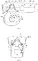
- FIG. 2 is a schematic front view showing the structure of a combined camera provided by the present application
- FIG. 3 is a schematic right view showing the structure of the combined camera as shown in FIG.2
- FIG.4 is a schematic cross-sectional structural view taken along line A-A of FIG. 2
- FIG. 5 is a schematic cross-sectional structural view taken along line B-B of FIG. 3 .
- the combined camera provided by a specific embodiment of the application includes a first camera housing 10 inside which a first camera 11 is provided.
- One side of the first camera housing 10 is provided with a rotating disc 30 that is rotatable relative to the first camera housing 10.
- a rotating bracket is fixed on the rotating disc 30, a second camera housing 20 that is rotatable relative to the rotating bracket is provided on the rotating bracket, and a second camera 21 is provided within the second camera housing 20.
- the rotation axes of the rotating disc 30 and the second camera housing 20 are perpendicular to each other in different planes, and are distinguished here by horizontal and vertical. That is, the rotating disc 30 rotates in a horizontal plane with respect to the first camera housing 10, and the second camera housing 20 rotates in a vertical plane with respect to the rotating bracket.
- rotation axes of both the rotating disc 30 and the second camera housing 20 may intersect, as long as monitoring requirements on the combined camera can be satisfied.
- the specific angle is set by those skilled in the art according to the actual structure.
- the first camera housing 10 has a concave rotating disc insertion hole 10a.
- the rotating disc 30 is completely inserted into the rotating disc insertion hole 10a and directly connected to the first camera housing 10 through a bearing.
- the first drive mechanism drives the rotating disc 30 to rotate in a horizontal plane relative to the first camera housing 10.
- the first drive mechanism comprises a first motor 12 and a first synchronous belt transmission mechanism.
- the first motor 12 is fixedly mounted within the first camera housing 10
- the first synchronous belt transmission mechanism includes a first driving synchronous pulley 13, a first driven synchronous pulley 14, and a first synchronous belt 15.
- the first driven synchronous pulley 14 is coaxially and fixedly connected to the rotating disc 30.
- the first driving synchronous pulley 13 is coaxially and fixedly connected to the electrical pivot of the first motor 12, and the first synchronous belt 15 is engaged with the first driving synchronous pulley 13 and the first driven synchronous pulley 14 to tension the internal teeth.
- the first motor 12 drives the rotating disc 30 to rotate in a horizontal plane with respect to the first camera housing 10 by the first synchronous belt transmission mechanism.
- the rotating disc 30 is fixedly connected to the rotating bracket, to which the second camera housing 20 is directly rotatably connected, and the second camera 21 is fixed to the second camera housing 20. Therefore, the rotation of the rotating disc 30 relative to the first camera housing 10 in the horizontal plane can drive the second camera 21 to rotate simultaneously to adjust the monitoring angle of the second camera 21 in the horizontal plane.
- the two rotating brackets are distinguished here by orientation words.
- the orientation words, left and right are defined on the basis of the second camera housing 21 in FIG. 4 . That is to say, of the two rotating brackets, the left rotating bracket 40 is located on the left side of the second camera housing 21, and the right rotating bracket 41 is located on the right side of the second camera housing 21.
- the second camera housing 20 is rotatably connected to the left rotating bracket 40 and right rotating bracket 41 by bearings.
- the left rotating bracket 40 has a bracket bearing hole
- the right rotating bracket has a bracket rotating shaft.
- the second camera housing 20 has a second camera housing bearing hole and a second camera housing rotating shaft.
- the bracket bearing hole, the bracket rotating shaft, the second camera housing bearing hole and the second camera housing rotating shaft are concentrically arranged.
- the left rotating bracket 40 and the second camera housing 20 are rotatably connected by a bearing mounted between the bracket bearing hole and the second camera housing rotating shaft.
- the right rotating bracket 41 and the second camera housing 20 are rotatably connected by a bearing mounted between the second camera housing bearing hole and the bracket rotating shaft.
- the second drive mechanism drives the second camera housing 20 to rotate in a horizontal plane with respect to the left and right rotating brackets 40, 41.
- the second drive mechanism comprises a second motor 22 and a second synchronous belt transmission mechanism.
- the second motor 22 is fixedly mounted within the second camera housing 20, and the second synchronous belt transmission mechanism includes a second driving synchronous pulley (not shown in the figures), a second driven synchronous pulley 24, and a second synchronous belt 25.
- the second driven synchronous pulley 24 is coaxially and fixedly connected to the bracket rotating shaft.
- the second driving synchronous pulley is coaxially and fixedly connected to the electrical pivot of the second motor 22.
- the second synchronous belt 25 is engaged with the second driving synchronous pulley and the second driven synchronous pulley 24 to tension the internal teeth.
- the second motor 22 drives the second camera housing 20 to rotate in a vertical plane by the second synchronous belt transmission mechanism.
- the second camera 21 is fixed to the second camera housing 20. Therefore, the rotation of the rotating disc 30 relative to the first camera housing 10 in the vertical plane can drive the second camera 21 to rotate to adjust the monitoring angle of the second camera 21 in the vertical plane.
- the second camera housing 20 of the combined camera is received at the recess of the concave hole 10a and is directly rotatably connected to the first camera housing 10 through both the rotating disc 30 and the rotating bracket, thereby eliminating the mounting bracket and the base in the existing combined camera of a gun-ball linkage structure, thus simplifying the overall structure and reducing its height dimension in the vertical direction.
- the first motor 12 and the second motor 22 are respectively provided within the first camera housing 10 and the second camera housing 20, so that the overall structure is simplified to a certain extent and the vertical dimension is reduced.
- synchronous belt transmission mechanisms are used as the first transmission mechanism and the second transmission mechanism, so that the combined camera has a compact overall structure and a stable transmission.
- the second transmission mechanism and the first transmission mechanism may also be a gear transmission mechanism, a sprocket transmission mechanism, or the like, as long as the requirements of the deceleration function and the assembly process are satisfied.
- the main board 60 of the combined camera is integrated with a power supply module, a core switching module, and a pan/tilt head module.
- the power supply module is used to supply power to the first camera 11, the second camera 21, the first motor 12, and the second motor 22.
- the pan/tilt head module is used to control the first motor 12 and the second motor 22, and the core switching module is used for signal switching between the first camera 11, the second camera 21 and a console (specifically including network, BNC, 485, uart, etc.).
- the combined camera further includes a connecting wire 50, which is electrically connected to the main board 60 at one end, and is extended, at the other end, through the first camera housing 10, the rotating disc 30 and into the second camera housing 20, and electrically connected to the second camera 21 and the second motor 22.
- the combined camera in this embodiment adopts a main board 60, which is integrated with a plurality of functional modules and supplies and controls both the first camera 11 and the second camera 21, greatly simplifying the structure thereof.
- the first camera housing 10 is a cylindrical housing.
- the first camera 11, the rotating disc 30 and the first motor 12 are sequentially arranged along the length direction of the first camera housing 10, and the main board 60 is arranged along the length direction of the first camera housing 10.
- the structure of the combined camera is compact and reasonable, which can further define the height dimension of the combined camera in the vertical direction.
- first cameras 11 there are three first cameras 11, which are sequentially distributed along an arc to acquire a first image of a monitoring area. It can be understood that the setting of the number of the first cameras 11 as three is illustrative only, and a person skilled in the art can determine an appropriate number of first cameras 11 according to actual monitoring requirements. That is, any number of the first cameras 11 are included within the protection scope of the present application.
- the first camera housing 10 and the second camera housing 20 are both waterproof sealing housings, such that the functional components such as the first camera 11, the second camera 21 and the main board 60 are sealingly mounted, so that the combined camera has a certain waterproof function, and then the scope of application thereof is expanded.
- the first camera housing 10 has a first waterproof sealing cavity 1a, a first image collecting hole and a first transparent cover 103.
- the first camera 11, the main board 60 and the first motor 12 are all located within the first waterproof sealing cavity 1a.
- the first image collecting hole is communicated with the first waterproof sealing cavity 1a and is blocked by the first transparent cover 103, enabling the first camera 11 to collect an image of an external object through the first transparent cover 103.
- the first camera housing 10 includes a first bottom shell 101 and a first shell cover 102. Wherein, the first bottom shell 101 and the first shell cover 102 are sealingly connected to form the first waterproof sealing cavity 1a.
- the first camera 11 is fixed within the first waterproof sealing cavity 1a, and the first image collecting hole is opened in the first bottom shell 101 or the first shell cover 102.
- the second camera housing 20 has a second waterproof sealing cavity 2a, a second image collecting hole and a second transparent cover 203.
- the second camera 21 and the second motor 22 are both located within the second waterproof sealing cavity 2a.
- the second image collecting hole is communicated with the second waterproof sealing cavity 2a and is blocked by the second transparent cover 203, enabling the second camera 21 to collect an image of an external object through the second transparent cover 203.
- the second camera housing 20 includes a second bottom shell 201 and a second shell cover 202.
- the second bottom shell 201 and the second shell cover 202 are sealingly connected to form the second waterproof sealing cavity 2a, and the second image collecting hole is opened in the second bottom shell 201 or the second shell cover 202.
- the first camera housing 10 is gun-shaped, and the second camera housing 20 is spherical.
Landscapes
- Engineering & Computer Science (AREA)
- Multimedia (AREA)
- Signal Processing (AREA)
- Physics & Mathematics (AREA)
- General Physics & Mathematics (AREA)
- Human Computer Interaction (AREA)
- Accessories Of Cameras (AREA)
- Studio Devices (AREA)
Claims (11)
- Kombinierte Kamera, umfassend ein erstes Kameragehäuse (10), in dem eine erste Kamera (11) vorgesehen ist, wobei eine Seite des ersten Kameragehäuses (10) mit einer Drehscheibe (30) versehen ist, die relativ zum ersten Kameragehäuse (10) um eine erste Achse drehbar ist; eine Drehhalterung, der an der Drehscheibe (30) befestigt ist; und ein zweites Kameragehäuse (20), das an der Drehhalterung vorgesehen ist und relativ zu der Drehhalterung um eine zweite Achse drehbar ist, wobei eine zweite Kamera (21) innerhalb des zweiten Kameragehäuses (20) vorgesehen ist; dadurch gekennzeichnet, dass das erste Kameragehäuse (10) ein konkaves Loch (10a) aufweist, in das die Drehscheibe (30) vollständig eingesetzt ist; und dass das zweite Kameragehäuse (20) an dem konkaven Loch (10a) aufgenommen und drehbar mit dem ersten Kameragehäuse (10) verbunden ist.
- Kombinierte Kamera nach Anspruch 1, die ferner einen ersten Motor (12) und einen zweiten Motor (22) aufweist, wobei der erste Motor (12) innerhalb des ersten Kameragehäuses (10) befestigt und so konfiguriert ist, dass er die Drehscheibe (30) antreibt, um sich relativ zum ersten Kameragehäuse (10) zu drehen, wobei der zweite Motor (22) innerhalb des zweiten Kameragehäuses (20) befestigt und so konfiguriert ist, dass er das zweite Kameragehäuse (20) antreibt, um sich relativ zur Drehhalterung zu drehen.
- Kombinierte Kamera nach Anspruch 2, die ferner eine Hauptplatine (60) aufweist, die mit einem Stromversorgungsmodul, einem Schwenk-/Neigekopfmodul und einem Kernschaltmodul integriert ist und die fest innerhalb des ersten Kameragehäuses (10) montiert ist.
- Kombinierte Kamera nach Anspruch 3, die ferner einen Verbindungsdraht (50) aufweist, der an einem Ende elektrisch mit der Hauptplatine (60) verbunden ist und am anderen Ende sich durch das erste Kameragehäuse (10), die Drehscheibe (30) und in das zweite Kameragehäuse (20) erstreckt und elektrisch mit der zweiten Kamera (21) und dem zweiten Motor (22) verbunden ist.
- Kombinierte Kamera nach Anspruch 3, wobei das erste Kameragehäuse (10) ein zylindrisches Gehäuse ist, die erste Kamera (11), die Drehscheibe (30) und der erste Motor (12) sequentiell entlang einer Längsrichtung des ersten Kameragehäuses (10) angeordnet sind, und die Hauptplatine (60) entlang einer Längsrichtung des ersten Kameragehäuses (10) angeordnet ist.
- Kombinierte Kamera nach Anspruch 3, wobei das erste Kameragehäuse (10) einen ersten wasserdichten Dichtungshohlraum (1a), eine erste Bildaufnahmeöffnung und eine erste transparente Abdeckung (103) aufweist; wobei die erste Kamera (11), die Hauptplatine (60) und der erste Motor (12) alle innerhalb des ersten wasserdichten Dichtungshohlraums (1a) angeordnet sind, wobei die erste Bildaufnahmeöffnung mit dem ersten wasserdichten Dichtungshohlraum (1a) in Verbindung steht und durch die erste transparente Abdeckung (103) blockiert ist, wodurch die erste Kamera (11) in die Lage versetzt wird, ein Bild eines externen Objekts durch die erste transparente Abdeckung (103) zu erfassen.
- Kombinierte Kamera nach Anspruch 6, wobei das erste Kameragehäuse (10) eine erste Bodenschale (101) und eine erste Schalenabdeckung (102) umfasst; wobei die erste Bodenschale (101) und die erste Schalenabdeckung (102) abdichtend miteinander verbunden sind, um den ersten wasserdichten Dichtungshohlraum (1a) zu bilden, und wobei die erste Bildaufnahmeöffnung in der ersten Bodenschale (101) oder in der ersten Schalenabdeckung (102) geöffnet ist.
- Kombinierte Kamera nach Anspruch 6, wobei es eine Vielzahl von ersten Kameras (11) gibt, die nacheinander entlang eines Bogens verteilt und innerhalb des ersten Kameragehäuses (10) installiert sind.
- Kombinierte Kamera nach Anspruch 3, wobei das zweite Kameragehäuse (20) einen zweiten wasserdichten Dichtungshohlraum (2a), eine zweite Bildaufnahmeöffnung und eine zweite transparente Abdeckung (203) aufweist; wobei die zweite Kamera (21) und der zweite Motor (22) beide innerhalb des zweiten wasserdichten Dichtungshohlraums (2a) angeordnet sind, wobei die zweite Bildaufnahmeöffnung mit dem zweiten wasserdichten Dichtungshohlraum (2a) in Verbindung steht und durch die zweite transparente Abdeckung (203) blockiert ist, wodurch die zweite Kamera (21) in die Lage versetzt wird, ein Bild eines externen Objekts durch die zweite transparente Abdeckung (203) aufzunehmen.
- Kombinierte Kamera nach irgendeinem der Ansprüche 1 bis 9, wobei das erste Kameragehäuse (10) pistolenförmig und das zweite Kameragehäuse (20) kugelförmig ist.
- Kombinierte Kamera nach einem der Ansprüche 1 bis 9, bei der zwei Drehhalterungen vorhanden sind, die jeweils an zwei Seiten des zweiten Kameragehäuses (20) vorgesehen und beide drehbar mit dem zweiten Kameragehäuse (20) verbunden sind, wobei die Drehachsen der Drehscheibe (30) und des zweiten Kameragehäuses (20) senkrecht zueinander stehen.
Applications Claiming Priority (2)
| Application Number | Priority Date | Filing Date | Title |
|---|---|---|---|
| CN201621156894.4U CN206117837U (zh) | 2016-10-24 | 2016-10-24 | 一种组合摄像机 |
| PCT/CN2017/085478 WO2018076674A1 (zh) | 2016-10-24 | 2017-05-23 | 一种组合摄像机 |
Publications (3)
| Publication Number | Publication Date |
|---|---|
| EP3531682A1 EP3531682A1 (de) | 2019-08-28 |
| EP3531682A4 EP3531682A4 (de) | 2019-08-28 |
| EP3531682B1 true EP3531682B1 (de) | 2020-11-04 |
Family
ID=58527914
Family Applications (1)
| Application Number | Title | Priority Date | Filing Date |
|---|---|---|---|
| EP17866187.2A Active EP3531682B1 (de) | 2016-10-24 | 2017-05-23 | Kombinierte kamera |
Country Status (4)
| Country | Link |
|---|---|
| US (1) | US10893179B2 (de) |
| EP (1) | EP3531682B1 (de) |
| CN (1) | CN206117837U (de) |
| WO (1) | WO2018076674A1 (de) |
Families Citing this family (16)
| Publication number | Priority date | Publication date | Assignee | Title |
|---|---|---|---|---|
| US10396201B2 (en) | 2013-09-26 | 2019-08-27 | Intel Corporation | Methods of forming dislocation enhanced strain in NMOS structures |
| CN206117837U (zh) * | 2016-10-24 | 2017-04-19 | 杭州海康威视数字技术股份有限公司 | 一种组合摄像机 |
| EP4235618A3 (de) | 2017-09-27 | 2023-09-06 | Zhejiang Dahua Technology Co., Ltd. | Überwachungsvorrichtung |
| WO2019184578A1 (zh) * | 2018-03-30 | 2019-10-03 | 杭州海康威视数字技术股份有限公司 | 一种双目摄像机 |
| USD892895S1 (en) * | 2018-03-30 | 2020-08-11 | Hangzhou Hikvision Digital Technology Co., Ltd. | Camera |
| US10909823B2 (en) * | 2018-12-27 | 2021-02-02 | Heidi Bear Enterprises, Llc | Home security light bulb adapter |
| US11741802B2 (en) * | 2018-12-27 | 2023-08-29 | John Otis Farneman | Home security light bulb adapter |
| CN110519510B (zh) * | 2019-08-08 | 2021-02-02 | 浙江大华技术股份有限公司 | 一种抓拍方法、装置、球机及存储介质 |
| CN113135151B (zh) * | 2020-01-19 | 2022-10-04 | 杭州海康汽车技术有限公司 | 摄像装置 |
| CN113630524B (zh) * | 2020-05-07 | 2023-01-31 | 杭州海康威视数字技术股份有限公司 | 摄像机 |
| CN113726986B (zh) * | 2020-05-25 | 2022-11-08 | 华为技术有限公司 | 具有无线通信功能的摄像机 |
| CN112013798A (zh) | 2020-08-13 | 2020-12-01 | 深圳市道通科技股份有限公司 | 一种轮图像采集组件、轮定位设备及车轮定位系统 |
| CN112776715A (zh) * | 2021-01-13 | 2021-05-11 | 广州驰享汽车用品有限公司 | 一种房车监控系统 |
| US20230023407A1 (en) * | 2021-07-23 | 2023-01-26 | Robert Bosch Gmbh | Camera assembly and method for assemblying |
| CN114935083B (zh) * | 2022-04-22 | 2023-05-05 | 滨州学院 | 基于计算机视觉的低空监视设备及其监测方法 |
| CN119957652A (zh) * | 2023-11-09 | 2025-05-09 | 杭州海康威视数字技术股份有限公司 | 具有减振机构的摄像机系统 |
Family Cites Families (14)
| Publication number | Priority date | Publication date | Assignee | Title |
|---|---|---|---|---|
| US6268882B1 (en) * | 1998-12-31 | 2001-07-31 | Elbex Video Ltd. | Dome shaped camera with simplified construction and positioning |
| US7629995B2 (en) * | 2004-08-06 | 2009-12-08 | Sony Corporation | System and method for correlating camera views |
| US7636105B2 (en) * | 2006-04-05 | 2009-12-22 | Etreppid Technologies Llc | Method and apparatus for providing motion control signals between a fixed camera and a PTZ camera |
| JP2009284452A (ja) | 2008-05-23 | 2009-12-03 | Advas Co Ltd | ハイブリッドビデオカメラ撮像装置及びシステム |
| WO2010137860A2 (ko) * | 2009-05-29 | 2010-12-02 | 주식회사 영국전자 | 지능형 감시 카메라 장치 및 이를 채용하는 영상 감시 시스템 |
| CN102714711A (zh) * | 2010-02-01 | 2012-10-03 | (株)荣国电子 | 追踪监视用摄像装置及采用此装置的远程监视系统 |
| CN201846413U (zh) * | 2010-11-04 | 2011-05-25 | 东莞市台骏电子有限公司 | 两头全方位监控摄像机 |
| WO2014043974A1 (zh) | 2012-09-24 | 2014-03-27 | 天津市亚安科技股份有限公司 | 多方向监控区域的监控装置 |
| CN202931456U (zh) * | 2012-11-09 | 2013-05-08 | 深圳市九天信息技术有限公司 | 红外摄像装置 |
| US9635224B2 (en) | 2014-04-18 | 2017-04-25 | Alarm.Com Incorporated | Pan and tilt camera with robotic movement |
| CN204305176U (zh) * | 2014-12-30 | 2015-04-29 | 杭州士兰微电子股份有限公司 | 组合摄像机 |
| CN204733286U (zh) * | 2015-07-13 | 2015-10-28 | 厦门优数科技有限公司 | 一种智能监控装置 |
| CN206117836U (zh) * | 2016-10-24 | 2017-04-19 | 杭州海康威视数字技术股份有限公司 | 一种组合摄像机 |
| CN206117837U (zh) * | 2016-10-24 | 2017-04-19 | 杭州海康威视数字技术股份有限公司 | 一种组合摄像机 |
-
2016
- 2016-10-24 CN CN201621156894.4U patent/CN206117837U/zh active Active
-
2017
- 2017-05-23 EP EP17866187.2A patent/EP3531682B1/de active Active
- 2017-05-23 WO PCT/CN2017/085478 patent/WO2018076674A1/zh not_active Ceased
- 2017-05-23 US US16/343,174 patent/US10893179B2/en active Active
Non-Patent Citations (1)
| Title |
|---|
| None * |
Also Published As
| Publication number | Publication date |
|---|---|
| CN206117837U (zh) | 2017-04-19 |
| EP3531682A1 (de) | 2019-08-28 |
| US10893179B2 (en) | 2021-01-12 |
| WO2018076674A1 (zh) | 2018-05-03 |
| EP3531682A4 (de) | 2019-08-28 |
| US20190246019A1 (en) | 2019-08-08 |
Similar Documents
| Publication | Publication Date | Title |
|---|---|---|
| US10893179B2 (en) | Combined camera | |
| CN208094669U (zh) | 一种双目摄像机 | |
| CN208094668U (zh) | 一种摄像机 | |
| ES2936115T3 (es) | Módulo de cámara, terminal móvil y método de control para el mismo | |
| EP4082183B1 (de) | Zweikammer-kamera | |
| WO2019184578A1 (zh) | 一种双目摄像机 | |
| CN214751536U (zh) | 一种轨道式智能巡检机器人的云台 | |
| CN208094671U (zh) | 一种双目摄像机 | |
| CN114756062A (zh) | 一种轨道式智能巡检机器人的云台 | |
| CN218825105U (zh) | 摄像机 | |
| CN110320730B (zh) | 一种双目摄像机 | |
| JP4401558B2 (ja) | 人型ロボット | |
| CN208190773U (zh) | 一种双目摄像机 | |
| CN216692883U (zh) | 一种具有二自由度云台的半球形监控摄像头装置 | |
| CN114838259A (zh) | 一种三维调节的摄像机云台及摄像机系统 | |
| CN211525958U (zh) | 云台、手持云台相机、头戴式云台相机及执法仪相机 | |
| CN217653603U (zh) | 巡检云台 | |
| CN115633230B (zh) | 摄像机 | |
| CN208754441U (zh) | 监控用一体式雷达云台 | |
| CN115623308B (zh) | 摄像机 | |
| CN216751874U (zh) | 一种镜头多光谱全景转台总成 | |
| CN106254746B (zh) | 一种能实现全角度覆盖的眼球型摄像头结构 | |
| CN112145916B (zh) | 云台摄像机 | |
| CN215300793U (zh) | 一种无线网覆盖工程监理视频监控设备 | |
| CN213751235U (zh) | 一种利用彩色和红外摄像头实现活体人脸识别门禁 |
Legal Events
| Date | Code | Title | Description |
|---|---|---|---|
| STAA | Information on the status of an ep patent application or granted ep patent |
Free format text: STATUS: THE INTERNATIONAL PUBLICATION HAS BEEN MADE |
|
| PUAI | Public reference made under article 153(3) epc to a published international application that has entered the european phase |
Free format text: ORIGINAL CODE: 0009012 |
|
| STAA | Information on the status of an ep patent application or granted ep patent |
Free format text: STATUS: REQUEST FOR EXAMINATION WAS MADE |
|
| 17P | Request for examination filed |
Effective date: 20190507 |
|
| A4 | Supplementary search report drawn up and despatched |
Effective date: 20190710 |
|
| AK | Designated contracting states |
Kind code of ref document: A1 Designated state(s): AL AT BE BG CH CY CZ DE DK EE ES FI FR GB GR HR HU IE IS IT LI LT LU LV MC MK MT NL NO PL PT RO RS SE SI SK SM TR |
|
| AX | Request for extension of the european patent |
Extension state: BA ME |
|
| DAV | Request for validation of the european patent (deleted) | ||
| DAX | Request for extension of the european patent (deleted) | ||
| GRAP | Despatch of communication of intention to grant a patent |
Free format text: ORIGINAL CODE: EPIDOSNIGR1 |
|
| STAA | Information on the status of an ep patent application or granted ep patent |
Free format text: STATUS: GRANT OF PATENT IS INTENDED |
|
| INTG | Intention to grant announced |
Effective date: 20200625 |
|
| GRAS | Grant fee paid |
Free format text: ORIGINAL CODE: EPIDOSNIGR3 |
|
| GRAA | (expected) grant |
Free format text: ORIGINAL CODE: 0009210 |
|
| STAA | Information on the status of an ep patent application or granted ep patent |
Free format text: STATUS: THE PATENT HAS BEEN GRANTED |
|
| AK | Designated contracting states |
Kind code of ref document: B1 Designated state(s): AL AT BE BG CH CY CZ DE DK EE ES FI FR GB GR HR HU IE IS IT LI LT LU LV MC MK MT NL NO PL PT RO RS SE SI SK SM TR |
|
| REG | Reference to a national code |
Ref country code: GB Ref legal event code: FG4D |
|
| REG | Reference to a national code |
Ref country code: CH Ref legal event code: EP |
|
| REG | Reference to a national code |
Ref country code: AT Ref legal event code: REF Ref document number: 1332321 Country of ref document: AT Kind code of ref document: T Effective date: 20201115 |
|
| REG | Reference to a national code |
Ref country code: IE Ref legal event code: FG4D |
|
| REG | Reference to a national code |
Ref country code: DE Ref legal event code: R096 Ref document number: 602017027159 Country of ref document: DE |
|
| REG | Reference to a national code |
Ref country code: NL Ref legal event code: MP Effective date: 20201104 |
|
| REG | Reference to a national code |
Ref country code: AT Ref legal event code: MK05 Ref document number: 1332321 Country of ref document: AT Kind code of ref document: T Effective date: 20201104 |
|
| PG25 | Lapsed in a contracting state [announced via postgrant information from national office to epo] |
Ref country code: FI Free format text: LAPSE BECAUSE OF FAILURE TO SUBMIT A TRANSLATION OF THE DESCRIPTION OR TO PAY THE FEE WITHIN THE PRESCRIBED TIME-LIMIT Effective date: 20201104 Ref country code: PT Free format text: LAPSE BECAUSE OF FAILURE TO SUBMIT A TRANSLATION OF THE DESCRIPTION OR TO PAY THE FEE WITHIN THE PRESCRIBED TIME-LIMIT Effective date: 20210304 Ref country code: RS Free format text: LAPSE BECAUSE OF FAILURE TO SUBMIT A TRANSLATION OF THE DESCRIPTION OR TO PAY THE FEE WITHIN THE PRESCRIBED TIME-LIMIT Effective date: 20201104 Ref country code: GR Free format text: LAPSE BECAUSE OF FAILURE TO SUBMIT A TRANSLATION OF THE DESCRIPTION OR TO PAY THE FEE WITHIN THE PRESCRIBED TIME-LIMIT Effective date: 20210205 Ref country code: NO Free format text: LAPSE BECAUSE OF FAILURE TO SUBMIT A TRANSLATION OF THE DESCRIPTION OR TO PAY THE FEE WITHIN THE PRESCRIBED TIME-LIMIT Effective date: 20210204 |
|
| PG25 | Lapsed in a contracting state [announced via postgrant information from national office to epo] |
Ref country code: AT Free format text: LAPSE BECAUSE OF FAILURE TO SUBMIT A TRANSLATION OF THE DESCRIPTION OR TO PAY THE FEE WITHIN THE PRESCRIBED TIME-LIMIT Effective date: 20201104 Ref country code: ES Free format text: LAPSE BECAUSE OF FAILURE TO SUBMIT A TRANSLATION OF THE DESCRIPTION OR TO PAY THE FEE WITHIN THE PRESCRIBED TIME-LIMIT Effective date: 20201104 Ref country code: BG Free format text: LAPSE BECAUSE OF FAILURE TO SUBMIT A TRANSLATION OF THE DESCRIPTION OR TO PAY THE FEE WITHIN THE PRESCRIBED TIME-LIMIT Effective date: 20210204 Ref country code: SE Free format text: LAPSE BECAUSE OF FAILURE TO SUBMIT A TRANSLATION OF THE DESCRIPTION OR TO PAY THE FEE WITHIN THE PRESCRIBED TIME-LIMIT Effective date: 20201104 Ref country code: IS Free format text: LAPSE BECAUSE OF FAILURE TO SUBMIT A TRANSLATION OF THE DESCRIPTION OR TO PAY THE FEE WITHIN THE PRESCRIBED TIME-LIMIT Effective date: 20210304 Ref country code: PL Free format text: LAPSE BECAUSE OF FAILURE TO SUBMIT A TRANSLATION OF THE DESCRIPTION OR TO PAY THE FEE WITHIN THE PRESCRIBED TIME-LIMIT Effective date: 20201104 Ref country code: LV Free format text: LAPSE BECAUSE OF FAILURE TO SUBMIT A TRANSLATION OF THE DESCRIPTION OR TO PAY THE FEE WITHIN THE PRESCRIBED TIME-LIMIT Effective date: 20201104 |
|
| REG | Reference to a national code |
Ref country code: LT Ref legal event code: MG9D |
|
| PG25 | Lapsed in a contracting state [announced via postgrant information from national office to epo] |
Ref country code: HR Free format text: LAPSE BECAUSE OF FAILURE TO SUBMIT A TRANSLATION OF THE DESCRIPTION OR TO PAY THE FEE WITHIN THE PRESCRIBED TIME-LIMIT Effective date: 20201104 |
|
| PG25 | Lapsed in a contracting state [announced via postgrant information from national office to epo] |
Ref country code: CZ Free format text: LAPSE BECAUSE OF FAILURE TO SUBMIT A TRANSLATION OF THE DESCRIPTION OR TO PAY THE FEE WITHIN THE PRESCRIBED TIME-LIMIT Effective date: 20201104 Ref country code: EE Free format text: LAPSE BECAUSE OF FAILURE TO SUBMIT A TRANSLATION OF THE DESCRIPTION OR TO PAY THE FEE WITHIN THE PRESCRIBED TIME-LIMIT Effective date: 20201104 Ref country code: LT Free format text: LAPSE BECAUSE OF FAILURE TO SUBMIT A TRANSLATION OF THE DESCRIPTION OR TO PAY THE FEE WITHIN THE PRESCRIBED TIME-LIMIT Effective date: 20201104 Ref country code: SM Free format text: LAPSE BECAUSE OF FAILURE TO SUBMIT A TRANSLATION OF THE DESCRIPTION OR TO PAY THE FEE WITHIN THE PRESCRIBED TIME-LIMIT Effective date: 20201104 Ref country code: RO Free format text: LAPSE BECAUSE OF FAILURE TO SUBMIT A TRANSLATION OF THE DESCRIPTION OR TO PAY THE FEE WITHIN THE PRESCRIBED TIME-LIMIT Effective date: 20201104 Ref country code: SK Free format text: LAPSE BECAUSE OF FAILURE TO SUBMIT A TRANSLATION OF THE DESCRIPTION OR TO PAY THE FEE WITHIN THE PRESCRIBED TIME-LIMIT Effective date: 20201104 |
|
| REG | Reference to a national code |
Ref country code: DE Ref legal event code: R097 Ref document number: 602017027159 Country of ref document: DE |
|
| PG25 | Lapsed in a contracting state [announced via postgrant information from national office to epo] |
Ref country code: DK Free format text: LAPSE BECAUSE OF FAILURE TO SUBMIT A TRANSLATION OF THE DESCRIPTION OR TO PAY THE FEE WITHIN THE PRESCRIBED TIME-LIMIT Effective date: 20201104 |
|
| PLBE | No opposition filed within time limit |
Free format text: ORIGINAL CODE: 0009261 |
|
| STAA | Information on the status of an ep patent application or granted ep patent |
Free format text: STATUS: NO OPPOSITION FILED WITHIN TIME LIMIT |
|
| 26N | No opposition filed |
Effective date: 20210805 |
|
| PG25 | Lapsed in a contracting state [announced via postgrant information from national office to epo] |
Ref country code: IT Free format text: LAPSE BECAUSE OF FAILURE TO SUBMIT A TRANSLATION OF THE DESCRIPTION OR TO PAY THE FEE WITHIN THE PRESCRIBED TIME-LIMIT Effective date: 20201104 Ref country code: NL Free format text: LAPSE BECAUSE OF FAILURE TO SUBMIT A TRANSLATION OF THE DESCRIPTION OR TO PAY THE FEE WITHIN THE PRESCRIBED TIME-LIMIT Effective date: 20201104 Ref country code: AL Free format text: LAPSE BECAUSE OF FAILURE TO SUBMIT A TRANSLATION OF THE DESCRIPTION OR TO PAY THE FEE WITHIN THE PRESCRIBED TIME-LIMIT Effective date: 20201104 |
|
| PG25 | Lapsed in a contracting state [announced via postgrant information from national office to epo] |
Ref country code: SI Free format text: LAPSE BECAUSE OF FAILURE TO SUBMIT A TRANSLATION OF THE DESCRIPTION OR TO PAY THE FEE WITHIN THE PRESCRIBED TIME-LIMIT Effective date: 20201104 |
|
| REG | Reference to a national code |
Ref country code: CH Ref legal event code: PL |
|
| PG25 | Lapsed in a contracting state [announced via postgrant information from national office to epo] |
Ref country code: LU Free format text: LAPSE BECAUSE OF NON-PAYMENT OF DUE FEES Effective date: 20210523 Ref country code: LI Free format text: LAPSE BECAUSE OF NON-PAYMENT OF DUE FEES Effective date: 20210531 Ref country code: MC Free format text: LAPSE BECAUSE OF FAILURE TO SUBMIT A TRANSLATION OF THE DESCRIPTION OR TO PAY THE FEE WITHIN THE PRESCRIBED TIME-LIMIT Effective date: 20201104 Ref country code: CH Free format text: LAPSE BECAUSE OF NON-PAYMENT OF DUE FEES Effective date: 20210531 |
|
| REG | Reference to a national code |
Ref country code: BE Ref legal event code: MM Effective date: 20210531 |
|
| PG25 | Lapsed in a contracting state [announced via postgrant information from national office to epo] |
Ref country code: IE Free format text: LAPSE BECAUSE OF NON-PAYMENT OF DUE FEES Effective date: 20210523 |
|
| PG25 | Lapsed in a contracting state [announced via postgrant information from national office to epo] |
Ref country code: IS Free format text: LAPSE BECAUSE OF FAILURE TO SUBMIT A TRANSLATION OF THE DESCRIPTION OR TO PAY THE FEE WITHIN THE PRESCRIBED TIME-LIMIT Effective date: 20210304 |
|
| PG25 | Lapsed in a contracting state [announced via postgrant information from national office to epo] |
Ref country code: BE Free format text: LAPSE BECAUSE OF NON-PAYMENT OF DUE FEES Effective date: 20210531 |
|
| REG | Reference to a national code |
Ref country code: DE Ref legal event code: R079 Ref document number: 602017027159 Country of ref document: DE Free format text: PREVIOUS MAIN CLASS: H04N0005225000 Ipc: H04N0023000000 |
|
| P01 | Opt-out of the competence of the unified patent court (upc) registered |
Effective date: 20230424 |
|
| PG25 | Lapsed in a contracting state [announced via postgrant information from national office to epo] |
Ref country code: CY Free format text: LAPSE BECAUSE OF FAILURE TO SUBMIT A TRANSLATION OF THE DESCRIPTION OR TO PAY THE FEE WITHIN THE PRESCRIBED TIME-LIMIT Effective date: 20201104 |
|
| PG25 | Lapsed in a contracting state [announced via postgrant information from national office to epo] |
Ref country code: HU Free format text: LAPSE BECAUSE OF FAILURE TO SUBMIT A TRANSLATION OF THE DESCRIPTION OR TO PAY THE FEE WITHIN THE PRESCRIBED TIME-LIMIT; INVALID AB INITIO Effective date: 20170523 |
|
| PG25 | Lapsed in a contracting state [announced via postgrant information from national office to epo] |
Ref country code: MK Free format text: LAPSE BECAUSE OF FAILURE TO SUBMIT A TRANSLATION OF THE DESCRIPTION OR TO PAY THE FEE WITHIN THE PRESCRIBED TIME-LIMIT Effective date: 20201104 |
|
| PG25 | Lapsed in a contracting state [announced via postgrant information from national office to epo] |
Ref country code: TR Free format text: LAPSE BECAUSE OF FAILURE TO SUBMIT A TRANSLATION OF THE DESCRIPTION OR TO PAY THE FEE WITHIN THE PRESCRIBED TIME-LIMIT Effective date: 20201104 |
|
| PG25 | Lapsed in a contracting state [announced via postgrant information from national office to epo] |
Ref country code: MT Free format text: LAPSE BECAUSE OF FAILURE TO SUBMIT A TRANSLATION OF THE DESCRIPTION OR TO PAY THE FEE WITHIN THE PRESCRIBED TIME-LIMIT Effective date: 20201104 |
|
| PGFP | Annual fee paid to national office [announced via postgrant information from national office to epo] |
Ref country code: DE Payment date: 20250513 Year of fee payment: 9 |
|
| PGFP | Annual fee paid to national office [announced via postgrant information from national office to epo] |
Ref country code: GB Payment date: 20250521 Year of fee payment: 9 |
|
| PGFP | Annual fee paid to national office [announced via postgrant information from national office to epo] |
Ref country code: FR Payment date: 20250530 Year of fee payment: 9 |
|
| REG | Reference to a national code |
Ref country code: DE Ref legal event code: R082 Ref document number: 602017027159 Country of ref document: DE Representative=s name: TERGAU & WALKENHORST INTELLECTUAL PROPERTY GMB, DE |