EP3530924A1 - Waste heat recovery system and turbine expander for the same - Google Patents
Waste heat recovery system and turbine expander for the same Download PDFInfo
- Publication number
- EP3530924A1 EP3530924A1 EP19159512.3A EP19159512A EP3530924A1 EP 3530924 A1 EP3530924 A1 EP 3530924A1 EP 19159512 A EP19159512 A EP 19159512A EP 3530924 A1 EP3530924 A1 EP 3530924A1
- Authority
- EP
- European Patent Office
- Prior art keywords
- nozzle
- working fluid
- turbine
- waste heat
- turbine expander
- Prior art date
- Legal status (The legal status is an assumption and is not a legal conclusion. Google has not performed a legal analysis and makes no representation as to the accuracy of the status listed.)
- Granted
Links
- 239000002918 waste heat Substances 0.000 title claims abstract description 85
- 238000011084 recovery Methods 0.000 title claims abstract description 77
- 239000012530 fluid Substances 0.000 claims abstract description 241
- 238000004891 communication Methods 0.000 claims abstract description 18
- 238000002485 combustion reaction Methods 0.000 claims abstract description 8
- 238000011144 upstream manufacturing Methods 0.000 claims description 9
- 230000008859 change Effects 0.000 description 10
- 238000004519 manufacturing process Methods 0.000 description 8
- CSCPPACGZOOCGX-UHFFFAOYSA-N Acetone Chemical compound CC(C)=O CSCPPACGZOOCGX-UHFFFAOYSA-N 0.000 description 6
- UHOVQNZJYSORNB-UHFFFAOYSA-N Benzene Chemical compound C1=CC=CC=C1 UHOVQNZJYSORNB-UHFFFAOYSA-N 0.000 description 6
- OKKJLVBELUTLKV-UHFFFAOYSA-N Methanol Chemical compound OC OKKJLVBELUTLKV-UHFFFAOYSA-N 0.000 description 6
- YXFVVABEGXRONW-UHFFFAOYSA-N Toluene Chemical compound CC1=CC=CC=C1 YXFVVABEGXRONW-UHFFFAOYSA-N 0.000 description 6
- 239000007788 liquid Substances 0.000 description 6
- LFQSCWFLJHTTHZ-UHFFFAOYSA-N Ethanol Chemical compound CCO LFQSCWFLJHTTHZ-UHFFFAOYSA-N 0.000 description 4
- LRHPLDYGYMQRHN-UHFFFAOYSA-N N-Butanol Chemical compound CCCCO LRHPLDYGYMQRHN-UHFFFAOYSA-N 0.000 description 4
- ATUOYWHBWRKTHZ-UHFFFAOYSA-N Propane Chemical compound CCC ATUOYWHBWRKTHZ-UHFFFAOYSA-N 0.000 description 4
- VNWKTOKETHGBQD-UHFFFAOYSA-N methane Chemical compound C VNWKTOKETHGBQD-UHFFFAOYSA-N 0.000 description 4
- 230000007704 transition Effects 0.000 description 4
- 239000012808 vapor phase Substances 0.000 description 4
- 238000003466 welding Methods 0.000 description 4
- 230000006870 function Effects 0.000 description 3
- 239000012071 phase Substances 0.000 description 3
- OTMSDBZUPAUEDD-UHFFFAOYSA-N Ethane Chemical compound CC OTMSDBZUPAUEDD-UHFFFAOYSA-N 0.000 description 2
- UFHFLCQGNIYNRP-UHFFFAOYSA-N Hydrogen Chemical compound [H][H] UFHFLCQGNIYNRP-UHFFFAOYSA-N 0.000 description 2
- 230000001133 acceleration Effects 0.000 description 2
- 230000000712 assembly Effects 0.000 description 2
- 238000000429 assembly Methods 0.000 description 2
- 239000001273 butane Substances 0.000 description 2
- -1 diesel Chemical compound 0.000 description 2
- 239000003502 gasoline Substances 0.000 description 2
- 239000001257 hydrogen Substances 0.000 description 2
- 229910052739 hydrogen Inorganic materials 0.000 description 2
- 239000003350 kerosene Substances 0.000 description 2
- IJDNQMDRQITEOD-UHFFFAOYSA-N n-butane Chemical compound CCCC IJDNQMDRQITEOD-UHFFFAOYSA-N 0.000 description 2
- OFBQJSOFQDEBGM-UHFFFAOYSA-N n-pentane Natural products CCCCC OFBQJSOFQDEBGM-UHFFFAOYSA-N 0.000 description 2
- BDERNNFJNOPAEC-UHFFFAOYSA-N propan-1-ol Chemical compound CCCO BDERNNFJNOPAEC-UHFFFAOYSA-N 0.000 description 2
- 239000001294 propane Substances 0.000 description 2
- 238000012546 transfer Methods 0.000 description 2
- XLYOFNOQVPJJNP-UHFFFAOYSA-N water Substances O XLYOFNOQVPJJNP-UHFFFAOYSA-N 0.000 description 2
- 238000003491 array Methods 0.000 description 1
- 239000006227 byproduct Substances 0.000 description 1
- 238000009833 condensation Methods 0.000 description 1
- 230000005494 condensation Effects 0.000 description 1
- 230000007423 decrease Effects 0.000 description 1
- 230000005611 electricity Effects 0.000 description 1
- 238000003754 machining Methods 0.000 description 1
- 238000000034 method Methods 0.000 description 1
- 238000012986 modification Methods 0.000 description 1
- 230000004048 modification Effects 0.000 description 1
- 238000012545 processing Methods 0.000 description 1
Images


Classifications
-
- F—MECHANICAL ENGINEERING; LIGHTING; HEATING; WEAPONS; BLASTING
- F02—COMBUSTION ENGINES; HOT-GAS OR COMBUSTION-PRODUCT ENGINE PLANTS
- F02G—HOT GAS OR COMBUSTION-PRODUCT POSITIVE-DISPLACEMENT ENGINE PLANTS; USE OF WASTE HEAT OF COMBUSTION ENGINES; NOT OTHERWISE PROVIDED FOR
- F02G5/00—Profiting from waste heat of combustion engines, not otherwise provided for
- F02G5/02—Profiting from waste heat of exhaust gases
-
- F—MECHANICAL ENGINEERING; LIGHTING; HEATING; WEAPONS; BLASTING
- F02—COMBUSTION ENGINES; HOT-GAS OR COMBUSTION-PRODUCT ENGINE PLANTS
- F02B—INTERNAL-COMBUSTION PISTON ENGINES; COMBUSTION ENGINES IN GENERAL
- F02B41/00—Engines characterised by special means for improving conversion of heat or pressure energy into mechanical power
- F02B41/02—Engines with prolonged expansion
- F02B41/10—Engines with prolonged expansion in exhaust turbines
-
- B—PERFORMING OPERATIONS; TRANSPORTING
- B05—SPRAYING OR ATOMISING IN GENERAL; APPLYING FLUENT MATERIALS TO SURFACES, IN GENERAL
- B05B—SPRAYING APPARATUS; ATOMISING APPARATUS; NOZZLES
- B05B1/00—Nozzles, spray heads or other outlets, with or without auxiliary devices such as valves, heating means
- B05B1/02—Nozzles, spray heads or other outlets, with or without auxiliary devices such as valves, heating means designed to produce a jet, spray, or other discharge of particular shape or nature, e.g. in single drops, or having an outlet of particular shape
-
- B—PERFORMING OPERATIONS; TRANSPORTING
- B05—SPRAYING OR ATOMISING IN GENERAL; APPLYING FLUENT MATERIALS TO SURFACES, IN GENERAL
- B05B—SPRAYING APPARATUS; ATOMISING APPARATUS; NOZZLES
- B05B13/00—Machines or plants for applying liquids or other fluent materials to surfaces of objects or other work by spraying, not covered by groups B05B1/00 - B05B11/00
- B05B13/02—Means for supporting work; Arrangement or mounting of spray heads; Adaptation or arrangement of means for feeding work
- B05B13/0278—Arrangement or mounting of spray heads
-
- F—MECHANICAL ENGINEERING; LIGHTING; HEATING; WEAPONS; BLASTING
- F01—MACHINES OR ENGINES IN GENERAL; ENGINE PLANTS IN GENERAL; STEAM ENGINES
- F01D—NON-POSITIVE DISPLACEMENT MACHINES OR ENGINES, e.g. STEAM TURBINES
- F01D1/00—Non-positive-displacement machines or engines, e.g. steam turbines
- F01D1/02—Non-positive-displacement machines or engines, e.g. steam turbines with stationary working-fluid guiding means and bladed or like rotor, e.g. multi-bladed impulse steam turbines
- F01D1/06—Non-positive-displacement machines or engines, e.g. steam turbines with stationary working-fluid guiding means and bladed or like rotor, e.g. multi-bladed impulse steam turbines traversed by the working-fluid substantially radially
-
- F—MECHANICAL ENGINEERING; LIGHTING; HEATING; WEAPONS; BLASTING
- F01—MACHINES OR ENGINES IN GENERAL; ENGINE PLANTS IN GENERAL; STEAM ENGINES
- F01D—NON-POSITIVE DISPLACEMENT MACHINES OR ENGINES, e.g. STEAM TURBINES
- F01D1/00—Non-positive-displacement machines or engines, e.g. steam turbines
- F01D1/18—Non-positive-displacement machines or engines, e.g. steam turbines without stationary working-fluid guiding means
- F01D1/22—Non-positive-displacement machines or engines, e.g. steam turbines without stationary working-fluid guiding means traversed by the working-fluid substantially radially
-
- F—MECHANICAL ENGINEERING; LIGHTING; HEATING; WEAPONS; BLASTING
- F01—MACHINES OR ENGINES IN GENERAL; ENGINE PLANTS IN GENERAL; STEAM ENGINES
- F01D—NON-POSITIVE DISPLACEMENT MACHINES OR ENGINES, e.g. STEAM TURBINES
- F01D17/00—Regulating or controlling by varying flow
- F01D17/10—Final actuators
- F01D17/105—Final actuators by passing part of the fluid
-
- F—MECHANICAL ENGINEERING; LIGHTING; HEATING; WEAPONS; BLASTING
- F01—MACHINES OR ENGINES IN GENERAL; ENGINE PLANTS IN GENERAL; STEAM ENGINES
- F01D—NON-POSITIVE DISPLACEMENT MACHINES OR ENGINES, e.g. STEAM TURBINES
- F01D17/00—Regulating or controlling by varying flow
- F01D17/10—Final actuators
- F01D17/12—Final actuators arranged in stator parts
- F01D17/18—Final actuators arranged in stator parts varying effective number of nozzles or guide conduits, e.g. sequentially operable valves for steam turbines
-
- F—MECHANICAL ENGINEERING; LIGHTING; HEATING; WEAPONS; BLASTING
- F01—MACHINES OR ENGINES IN GENERAL; ENGINE PLANTS IN GENERAL; STEAM ENGINES
- F01D—NON-POSITIVE DISPLACEMENT MACHINES OR ENGINES, e.g. STEAM TURBINES
- F01D9/00—Stators
- F01D9/02—Nozzles; Nozzle boxes; Stator blades; Guide conduits, e.g. individual nozzles
- F01D9/04—Nozzles; Nozzle boxes; Stator blades; Guide conduits, e.g. individual nozzles forming ring or sector
- F01D9/047—Nozzle boxes
-
- F—MECHANICAL ENGINEERING; LIGHTING; HEATING; WEAPONS; BLASTING
- F01—MACHINES OR ENGINES IN GENERAL; ENGINE PLANTS IN GENERAL; STEAM ENGINES
- F01K—STEAM ENGINE PLANTS; STEAM ACCUMULATORS; ENGINE PLANTS NOT OTHERWISE PROVIDED FOR; ENGINES USING SPECIAL WORKING FLUIDS OR CYCLES
- F01K11/00—Plants characterised by the engines being structurally combined with boilers or condensers
- F01K11/02—Plants characterised by the engines being structurally combined with boilers or condensers the engines being turbines
-
- F—MECHANICAL ENGINEERING; LIGHTING; HEATING; WEAPONS; BLASTING
- F01—MACHINES OR ENGINES IN GENERAL; ENGINE PLANTS IN GENERAL; STEAM ENGINES
- F01N—GAS-FLOW SILENCERS OR EXHAUST APPARATUS FOR MACHINES OR ENGINES IN GENERAL; GAS-FLOW SILENCERS OR EXHAUST APPARATUS FOR INTERNAL COMBUSTION ENGINES
- F01N5/00—Exhaust or silencing apparatus combined or associated with devices profiting from exhaust energy
- F01N5/04—Exhaust or silencing apparatus combined or associated with devices profiting from exhaust energy the devices using kinetic energy
-
- F—MECHANICAL ENGINEERING; LIGHTING; HEATING; WEAPONS; BLASTING
- F02—COMBUSTION ENGINES; HOT-GAS OR COMBUSTION-PRODUCT ENGINE PLANTS
- F02C—GAS-TURBINE PLANTS; AIR INTAKES FOR JET-PROPULSION PLANTS; CONTROLLING FUEL SUPPLY IN AIR-BREATHING JET-PROPULSION PLANTS
- F02C6/00—Plural gas-turbine plants; Combinations of gas-turbine plants with other apparatus; Adaptations of gas- turbine plants for special use
- F02C6/04—Gas-turbine plants providing heated or pressurised working fluid for other apparatus, e.g. without mechanical power output
- F02C6/10—Gas-turbine plants providing heated or pressurised working fluid for other apparatus, e.g. without mechanical power output supplying working fluid to a user, e.g. a chemical process, which returns working fluid to a turbine of the plant
-
- F—MECHANICAL ENGINEERING; LIGHTING; HEATING; WEAPONS; BLASTING
- F05—INDEXING SCHEMES RELATING TO ENGINES OR PUMPS IN VARIOUS SUBCLASSES OF CLASSES F01-F04
- F05D—INDEXING SCHEME FOR ASPECTS RELATING TO NON-POSITIVE-DISPLACEMENT MACHINES OR ENGINES, GAS-TURBINES OR JET-PROPULSION PLANTS
- F05D2220/00—Application
- F05D2220/60—Application making use of surplus or waste energy
-
- F—MECHANICAL ENGINEERING; LIGHTING; HEATING; WEAPONS; BLASTING
- F05—INDEXING SCHEMES RELATING TO ENGINES OR PUMPS IN VARIOUS SUBCLASSES OF CLASSES F01-F04
- F05D—INDEXING SCHEME FOR ASPECTS RELATING TO NON-POSITIVE-DISPLACEMENT MACHINES OR ENGINES, GAS-TURBINES OR JET-PROPULSION PLANTS
- F05D2250/00—Geometry
- F05D2250/50—Inlet or outlet
- F05D2250/51—Inlet
-
- Y—GENERAL TAGGING OF NEW TECHNOLOGICAL DEVELOPMENTS; GENERAL TAGGING OF CROSS-SECTIONAL TECHNOLOGIES SPANNING OVER SEVERAL SECTIONS OF THE IPC; TECHNICAL SUBJECTS COVERED BY FORMER USPC CROSS-REFERENCE ART COLLECTIONS [XRACs] AND DIGESTS
- Y02—TECHNOLOGIES OR APPLICATIONS FOR MITIGATION OR ADAPTATION AGAINST CLIMATE CHANGE
- Y02T—CLIMATE CHANGE MITIGATION TECHNOLOGIES RELATED TO TRANSPORTATION
- Y02T10/00—Road transport of goods or passengers
- Y02T10/10—Internal combustion engine [ICE] based vehicles
- Y02T10/12—Improving ICE efficiencies
Definitions
- the present invention relates generally to a waste heat recovery system for recovering waste heat of an internal combustion engine.
- ICEs Internal combustion engines
- waste heat recovery systems typically utilize this discarded heat to produce electricity that may further be used to power electronic components of a motor vehicle.
- Conventional waste heat recovery systems include a turbine expander, a flow control device, and a controller.
- the turbine expander outputs power based on a working fluid.
- the turbine expander includes a turbine blade that is rotatable by the working fluid, a shaft coupled to and rotatable by the turbine blade and extending along a longitudinal axis, and a nozzle assembly for directing the working fluid to the turbine blade for rotating the turbine blade.
- Conventional nozzle assemblies have a nozzle block, a first nozzle component, and a second nozzle component.
- the nozzle block is disposed about the shaft and is adjacent the turbine expander.
- the first nozzle component is integral with nozzle block for accelerating the working fluid and defines a first nozzle
- the second nozzle component is integral with the nozzle block for accelerating the working fluid and defines a second nozzle.
- the first and second nozzles have the same geometrical configuration.
- ORC organic Rankine cycle
- the working fluid may include at least one of ethanol, methanol, kerosene, gasoline, diesel, propanol, butanol, water, benzene, toluene, methane, ethane, propane, butane, acetone, or liquid hydrogen.
- Heat discarded by the ICE heats the working fluid so that the working fluid undergoes liquid-vapor phase change from a liquid state to a vapor state. In the vapor state, the working fluid is more suitable for rotating the turbine blade.
- nozzle assemblies are difficult to manufacture. Specifically, defining nozzles in nozzle components that are integral with the nozzle block requires extensive, precise machining due to the size of the nozzle block, which increases manufacturing time and cost.
- a waste heat recovery system for recovering waste heat of in internal combustion engine includes a turbine expander for outputting power based on a working fluid.
- the turbine expander includes a turbine blade rotatable by the working fluid, a shaft coupled to and rotatable by the turbine blade and extending along a longitudinal axis, and a nozzle assembly for directing the working fluid to the turbine blade for rotating the turbine blade.
- the nozzle assembly includes a nozzle block disposed about the shaft and adjacent the turbine blade, a first nozzle component coupled to the nozzle block for accelerating the working fluid, and a second nozzle component coupled to the nozzle block for accelerating the working fluid.
- the first nozzle component defines a first nozzle having a first geometrical configuration.
- the second nozzle component defines a second nozzle having a second geometrical configuration that is different from the first geometrical configuration.
- the waste heat recovery system also includes a flow control device in fluid communication with the turbine expander for directing the working fluid to at least one of the first and second nozzles or to bypass the turbine expander.
- the waste heat recovery system further includes a controller in communication with the flow control device and adapted to control the flow control device to direct the working fluid to at least one of the first and second nozzles or to bypass the turbine expander.
- a waste heat recovery system for recovering waste heat of in internal combustion engine includes a turbine expander for outputting power based on a working fluid.
- the turbine expander includes a turbine blade rotatable by the working fluid, a shaft coupled to and rotatable by the turbine blade and extending along a longitudinal axis, and a nozzle assembly for directing the working fluid to the turbine blade for rotating the turbine blade.
- the nozzle assembly includes a nozzle block disposed about the shaft and adjacent the turbine blade, with the nozzle block defining a bore.
- the nozzle assembly also includes a nozzle component removably coupled to the nozzle block such that the nozzle component is selectively disposed in the bore for accelerating the working fluid.
- the nozzle component defines a nozzle.
- the waste heat recovery system also includes a flow control device in fluid communication with the turbine expander for directing the working fluid to the nozzle or to bypass the turbine expander.
- the waste heat recovery system further includes a controller in communication with the flow control device and adapted to control the flow control device to direct the working fluid the nozzle or to bypass the turbine expander.
- the turbine expander as described above, wherein at least a portion of the nozzle block may be disposed between the nozzle and the turbine blade.
- the waste heat recovery system having first and second nozzles that have different geometrical configurations allows for the working fluid to pass through each of the first and second nozzles at different working fluid pressures and mass flow rates, thereby expand the operating range of the waste heat recovery system.
- the first and second nozzles provide a series of incremental steps for working fluid pressures and mass flow rates that allows for greater controllability of the waste heat recovery system.
- the waste heat recovery system having a nozzle component that is removably coupled to the nozzle block reduces manufacturing complexity of the waste heat recovery system. Specifically, the nozzle of the nozzle component may be machined independently of the nozzle block, thereby reducing manufacturing time and manufacturing costs.
- a waste heat recovery system 20 for recovering waste heat of an internal combustion engine is schematically shown in FIG. 1 .
- the waste heat recovery system 20 includes a turbine expander 22 for outputting power based on a working fluid, a flow control device 24 in fluid communication with the turbine expander 22, and a controller 26 in communication with the flow control device 24.
- the turbine expander 22 includes a turbine blade 28 rotatable by the working fluid. As best shown in FIG. 2 , the turbine expander 22 also includes a shaft 30 coupled to and rotatable by the turbine blade 28. The shaft 30 extends along a longitudinal axis A. The working fluid causes rotation of the turbine blade 28 about the longitudinal axis A of the shaft 30.
- the turbine expander 22 further includes a nozzle assembly 32 for directing the working fluid to the turbine blade 28 for rotating the turbine blade 28.
- the nozzle assembly 32 includes a nozzle block 34 disposed about the shaft 30 and adjacent the turbine blade 28.
- the nozzle block 34 has an annular configuration.
- the nozzle block 34 may have any configuration suitable for directing the working fluid to the turbine blade 28.
- the nozzle block 34 may have a first face 36 facing the turbine blade 28, as best shown in FIG. 4 , and a second face 38 facing opposite the first face 36, as best shown in FIG. 2 .
- the nozzle assembly 32 also includes a nozzle component 40 coupled to the nozzle block 34 for accelerating the working fluid.
- the nozzle component 40 defines a nozzle 42.
- the nozzle component 40 is integral (i.e., one-piece) with the nozzle block 34, as shown in FIG. 2 .
- the nozzle component 40 may be separate from (i.e., not integral with) the nozzle block 34.
- the nozzle 42 has a geometrical configuration.
- the geometrical configuration may be a converging-type configuration, a diverging-type configuration, or a de Laval (converging-diverging-type) configuration.
- the geometrical configuration is a de Laval configuration as shown in FIGS. 5 and 6A .
- the nozzle 42 may have a working fluid inlet 44, a converging section 46, a diverging section 48, a throat section 50 separating the converging section 46 from the diverging section 48, and a working fluid outlet 52.
- the converging section 46 extends from the working fluid inlet 44 to the throat section 50.
- the cross-sectional area of the nozzle 42 gradually decreases from the working fluid inlet 44 to the throat section 50.
- the diverging section 48 extends from the throat section 50 to the working fluid outlet 52.
- the cross-sectional area of the nozzle 42 gradually increases from the throat section 50 to the working fluid outlet 52.
- the throat section 50 is where the cross-sectional area of the nozzle 42 is at a minimum.
- the minimum cross-sectional area of the nozzle 42 is referred to as the throat cross-sectional area 54, as best shown in Fig 7A .
- the working fluid passes through the converging section 46 of the nozzle 42 to the throat section 50. If the working fluid has a suitable pressure and mass flow rate, the working fluid velocity is choked at the throat section 50. Whether the working fluid is of a suitable pressure and mass flow rate for the working fluid velocity to be choked at the throat section 50 is based on the throat cross-sectional area 54.
- the working fluid is then expanded in the diverging section 48 such that the working fluid velocity is increased to a supersonic velocity. In this manner, the nozzle 42 accelerates the working fluid to supersonic velocities.
- the nozzle component 40 may be integral with the nozzle block 34. In other embodiments, the nozzle component 40 may be fixed to the nozzle block 34, for example, by welding. As shown in FIGS. 8 and 9 , the nozzle component 40 may be removably coupled to the nozzle block 34. When the nozzle component 40 is removably coupled to the nozzle block 34, the nozzle block 34 may define a bore 56 for selectively receiving the nozzle component 40. In this manner, the nozzle component 40 may be selectively disposed in the bore 56.
- manufacturing complexity of the waste heat recovery system 20 is reduced.
- the nozzle 42 of the nozzle component 40 may be machined and/or cast independently of the nozzle block 34, thereby reducing manufacturing time and manufacturing costs.
- the removably coupled nozzle component 40 also allows for greater customizability of the waste heat recovery system 20 due to the interchangeability of the nozzle component 40.
- the nozzle component 40 When the nozzle component 40 is removably coupled to the nozzle block 34, the nozzle component may include screw threads.
- the nozzle block 34 may also include screw threads so that the nozzle component may be removably coupled to the nozzle block 34.
- the nozzle component 40 may be removably coupled to the nozzle block 34 by a transition or interference fit.
- the nozzle block 34 when the nozzle component 40 is removably coupled to the nozzle block 34, at least a portion of the nozzle block 34 is disposed between the nozzle 42 and the turbine blade 28 as shown in FIGS. 8 and 9 . In other embodiments, the nozzle block 34 is disposed entirely between the nozzle 42 and the turbine blade 28. In some embodiments, no portion of the nozzle block 34 is disposed between the nozzle 42 and the turbine blade 28.
- the nozzle component 40 may be further defined as a first nozzle component 40, and the nozzle 42 may be further defined as a first nozzle 42. Moreover, each section of the nozzle 42 described above may be further defined as a first section (e.g. first throat section 50, first throat cross-sectional area 54, etc.).
- the nozzle assembly 32 may also include a second nozzle component 58 coupled to the nozzle block 34 for accelerating the working fluid. As shown in FIGS. 5 and 6B , when present, the second nozzle component 58 defines a second nozzle 60. In one embodiment, as best shown in FIG. 2 , the second nozzle component 58 is integral (i.e., one-piece) with the nozzle block 34. In another embodiment, as described in further detail below, the second nozzle component 58 may be separate from (i.e., not integral with) the nozzle block 34.
- the second nozzle 60 has a second geometrical configuration.
- the second geometrical configuration may be a converging-type configuration, a diverging-type configuration, or a de Laval (converging-diverging-type) configuration.
- the second geometrical configuration is a de Laval configuration as shown in FIGS. 5 and 6B .
- the second nozzle 60 may have a second working fluid inlet 62, a second converging section 64, a second diverging section 66, a second throat section 68 separating the second converging section 64 from the second diverging section 66, and a second working fluid outlet 70. As best seen in FIG.
- the minimum cross-sectional area of the second nozzle 60 is referred to as the second throat cross-sectional area 72. It is to be appreciated that the description of the first working fluid inlet 44, the first converging section 46, the first diverging section 48, the first throat section 50, and the first working fluid outlet 52 also applies to the second working fluid inlet 62, the second converging section 64, the second diverging section 66, the second throat section 68, and the second working fluid outlet 70.
- the second geometrical configuration of the second nozzle 60 when present, is different from the first geometrical configuration of the first nozzle 42.
- the first and second geometrical configurations may be different types of configurations.
- the first geometrical configuration may be a converging-type configuration and the second geometrical configuration may be a de Laval configuration.
- the first and second geometrical configurations may be the same type of configuration but have corresponding sections that differ from each other.
- first and second geometrical configurations are de Laval configurations
- at least one of the first working fluid inlet 44, first converging section 46, first throat section 50, first diverging section 48, and first working fluid outlet 52 of the first nozzle 42 is different from the corresponding second working fluid inlet 62, second converging section 64, second throat section 68, second diverging section 66, and second working fluid outlet 70 of the second nozzle 60.
- the second throat cross-sectional area 72 is different from the first throat cross-sectional area 54, as shown in FIGS. 7A and 7B .
- whether the velocity of the working fluid is choked at the first and second throat sections 50, 68 is determined by the first and second throat cross-sectional areas 54, 72 and the working fluid pressure and mass flow rate. Because the first and second throat cross-sectional areas 54, 72 are different, the working fluid pressure and mass flow rate may be suitable for one of the first and second nozzles 42, 60 to accelerate the working fluid to a supersonic velocity and not the other of the first and second nozzles 42, 60.
- heat recovered by the waste heat recovery system 20 may change the working fluid pressure and mass flow rate such that both the first and second nozzles 42, 60 may accelerate the working fluid to a supersonic velocity.
- the first and second nozzles 42, 60 expand the operating range of the waste heat recovery system 20.
- the first and second nozzles 42, 60 expand the range of working fluid mass flow rates that the waste heat recovery system 20 may be operated at for a specific working fluid pressure. This advantageously allows the waste heat recovery system 20 to retain maximum cycle efficiency and power output for a broader range of ICE operating states, as described in further detail below.
- the second nozzle component 58 may be integral with the nozzle block 34.
- the second nozzle component 58 may be fixed to the nozzle block 34, for example, by welding.
- the second nozzle component 58 may be removably coupled to the nozzle block 34.
- the nozzle block may define a second bore 74 for selectively receiving the second nozzle component 58. In this manner, the second nozzle component 58 may be selectively disposed in the second bore 74.
- the second nozzle component 58 When the second nozzle component 58 is removably coupled to the nozzle block 34, the second nozzle component may include screw threads.
- the nozzle block 34 may also include screw threads so that the second nozzle component 58 may be removably coupled to the nozzle block 34.
- the second nozzle component 58 may be removably coupled to the nozzle block 34 by a transition or interference fit.
- the nozzle block 34 when the second nozzle component 58 is removably coupled to the nozzle block 34, at least a portion of the nozzle block 34 is disposed between the second nozzle 60 and the turbine blade 28 as shown in FIGS. 8 and 9 . In other embodiments, the nozzle block 34 is disposed entirely between the second nozzle 60 and the turbine blade 28. In some embodiments, no portion of the nozzle block 34 is disposed between the second nozzle 60 and the turbine blade 28.
- first and second nozzle components 42, 60 may be circumferentially spaced about the longitudinal axis A. In other embodiments, the first and second nozzle components 42, 60 may be spaced equally and circumferentially about the longitudinal axis A.
- the nozzle assembly 32 may also include a third nozzle component 76 coupled to the nozzle block 34 for accelerating the working fluid.
- the third nozzle component 76 defines a third nozzle 78.
- the third nozzle component 76 is integral (i.e., one-piece) with the nozzle block 34.
- the third nozzle component 76 may be separate from (i.e., not integral with) the nozzle block 34.
- the third nozzle 78 has a third geometrical configuration.
- the third geometrical configuration may be a converging-type configuration, a diverging-type configuration, or a de Laval (converging-diverging-type) configuration.
- the third geometrical configuration is a de Laval configuration as shown in FIGS. 5 and 6C .
- the third nozzle 78 may have a third working fluid inlet 80, a third converging section 82, a third diverging section 84, a third throat section 86 separating the third converging section 82 from the third diverging section 84, and a third working fluid outlet 88. As shown in FIG.
- the minimum cross-sectional area of the third nozzle 78 is referred to as the third throat cross-sectional area 90. It is to be appreciated that the description of the first working fluid inlet 44, the first converging section 46, the first diverging section 48, the first throat section 50, and the first working fluid outlet 52 also applies to the third working fluid inlet 80, the third converging section 82, the third diverging section 84, the third throat section 86, and the third working fluid outlet 88.
- the third geometrical configuration of the third nozzle 78 when present, is different from at least one of the first and second geometrical configurations of the first and second nozzles 42, 60.
- the third geometrical configuration may be a different type of configuration to at least one of the first and second geometrical configurations.
- the first geometrical configuration may be a converging-type configuration
- the second geometrical configuration may be a de Laval configuration
- the third geometrical configuration may be a de Laval configuration.
- the first, second, and third geometrical configurations may be the same type of configuration but have corresponding sections that differ from each other.
- the third working fluid inlet 80, third converging section 82, third diverging section 84, third throat section 86, third diverging section 84and third working fluid outlet 88 of the third nozzle 78 is different from the corresponding first working fluid inlet 44, first converging section 46, first diverging section 48, first throat section 50, and first working fluid outlet 52 of the first nozzle 42 and/or the second working fluid inlet 62, second converging section 64, second diverging section 66, second throat section 68, and second working fluid outlet 70 of the second nozzle 60.
- the third throat cross-sectional area 90 is different from at least one of first and second throat cross-sectional areas 54, 72. In other embodiments, when the first, second, and third geometrical configurations are de Laval configurations, the first, second, and third throat cross-sectional areas 54, 72, 90 are different from each other as shown in FIGS. 7A-C .
- the number of combinations of nozzles that the working fluid may pass through prior to rotating the turbine blade 28 is 2 n - 1, wherein n is the number of nozzles included in the nozzle assembly 32.
- the working fluid may pass through seven different combinations of the first, second, and third nozzles 42, 60, 78 prior to rotating the turbine blade 28 based on the working fluid pressure and mass flow rate.
- the working fluid may pass through the first nozzle 42 alone, the second nozzle 60 alone, the third nozzle 78 alone, the first and second nozzles 42, 60 alone, the first and third nozzles 42, 78 alone, the second and third nozzles 60, 78 alone, and the first, second, and third nozzles 42, 60, 78.
- first, second, and third geometrical configurations are de Laval configurations and the first, second, and third throat cross-sectional areas 54, 72, 90 are different from each other, whether the velocity of the working fluid is choked at the first, second and third throat sections 50, 68, 86 is determined by the first, second, and third throat cross-sectional areas 54, 72, 90 and the working fluid pressure and mass flow rate, as described above. Because the first, second, and third throat cross-sectional areas 54, 72, 90 are different, the working fluid pressure and mass flow rate may be suitable for one of first, second, and third nozzles 42, 60, 78 to accelerate the working fluid to a supersonic velocity and not the other of the first, second, and third nozzles 42, 60, 78.
- heat recovered by the waste heat recovery system 20 may change the working fluid pressure and mass flow rate such that different combinations of the first, second, and third nozzles 42, 60, 78 may accelerate the working fluid to a supersonic velocity.
- the first second, and third nozzles 42, 60, 78 expand the operating range of the waste heat recovery system 20.
- the first, second, and third nozzles 42, 60, 78 expand the range of working fluid mass flow rates that the waste heat recovery system 20 may be operated at for a specific working fluid pressure. This advantageously allows the waste heat recovery system 20 to retain maximum cycle efficiency and power output for a broader range of ICE operating states, as described in further detail below.
- the third nozzle component 76 may be integral with the nozzle block 34. In other embodiments, the third nozzle component 76 may be fixed to the nozzle block 34, for example, by welding. As shown in FIGS. 8 and 9 , in still other embodiments, the third nozzle component 76 may be removably coupled to the nozzle block 34. When the third nozzle component 76 is removably coupled to the nozzle block 34, the nozzle block may define a third bore 92 for selectively receiving the third nozzle component 76. In this manner, the third nozzle component 76 may be selectively disposed in the third bore 92.
- the third nozzle component 76 When the third nozzle component 76 is removably coupled to the nozzle block 34, the third nozzle component 76 may include screw threads.
- the nozzle block 34 may also include screw threads so that the third nozzle component 76 may be removably coupled to the nozzle block 34.
- the third nozzle component 76 may be removably coupled to the nozzle block 34 by a transition or interference fit.
- the third nozzle component 76 when the third nozzle component 76 is removably coupled to the nozzle block 34, at least a portion of the nozzle block 34 is disposed between the third nozzle 78 and the turbine blade 28 as shown in FIGS. 8 and 9 . In other embodiments, the nozzle block 34 is disposed entirely between the third nozzle 78 and the turbine blade 28. In some embodiments, no portion of the nozzle block 34 is disposed between the third nozzle 78 and the turbine blade 28.
- first, second, and third nozzle components 40, 58, 76 may be circumferentially spaced about the longitudinal axis A. In other embodiments, the first, second, and third nozzle components 40, 58, 76 may be spaced equally and circumferentially about the longitudinal axis A.
- the nozzle assembly 32 may also include a fourth nozzle component 94 coupled to the nozzle block 34 for accelerating the working fluid.
- the fourth nozzle component 94 defines a fourth nozzle 96.
- the fourth nozzle component 94 is integral (i.e., one-piece) with the nozzle block 34.
- the fourth nozzle component 94 may be separate from (i.e., not integral with) the nozzle block 34.
- the fourth nozzle 96 has a fourth geometrical configuration.
- the fourth geometrical configuration may be a converging-type configuration, a diverging-type configuration, or a de Laval (converging-diverging-type) configuration.
- the fourth geometrical configuration is a de Laval configuration as shown in FIGS. 5 and 6D .
- the fourth nozzle 96 may have a fourth working fluid inlet 98, a fourth converging section 100, a fourth diverging section 102, a fourth throat section 104 separating the fourth converging section 100 from the fourth diverging section 102, and a fourth working fluid outlet 106. As shown in FIG.
- the minimum cross-sectional area of the fourth nozzle 96 is referred to as the fourth throat cross-sectional area 108. It is to be appreciated that the description of the first working fluid inlet 44, the first converging section 46, the first diverging section 48, the first throat section 50, and the first working fluid outlet 52 also applies to the fourth working fluid inlet 98, the fourth converging section 100, the fourth diverging section 102, the fourth throat section 104, and the fourth working fluid outlet 106.
- the fourth geometrical configuration of the fourth nozzle 96 when present, is different from at least one of the first, second, and third geometrical configurations of the first, second, and third nozzles 42, 60, 78.
- the fourth geometrical configuration may be a different type of configuration to at least one of the first, second, and third geometrical configurations.
- the first geometrical configuration may be a converging-type configuration
- the second geometrical configuration may be a de Laval configuration
- the third geometrical configuration may be a de Laval configuration
- the fourth geometrical configuration may be a diverging-type configuration.
- the first, second, third geometrical, and fourth configurations may be the same type of configuration but have corresponding sections that differ from each other.
- the first, second, third, and fourth geometrical configurations are de Laval configurations
- at least one of the fourth working fluid inlet 98, fourth converging section 100, fourth diverging section 102, fourth throat section 104, and fourth working fluid outlet 106 of the fourth nozzle 96 is different from the corresponding first working fluid inlet 44, first converging section 46, first diverging section 48, first throat section 50, and first working fluid outlet 52 of the first nozzle 42, the second working fluid inlet 62, second converging section 64, second diverging section 66, second throat section 68, and second working fluid outlet 70 of the second nozzle 60, and/or the third working fluid inlet 80, third converging section 82, third diverging section 84, third throat section 86, and third working fluid outlet 88 of the third nozzle 78.
- the fourth throat cross-sectional area 108 is different from at least one of first, second, and third throat cross-sectional areas 54, 72, 90. In other embodiments, when the first, second, third, and fourth geometrical configurations are de Laval configurations, the first, second, third, and fourth throat cross-sectional areas 54, 72, 90, 108 are different from each other as shown in FIGS. 7A-D .
- the working fluid my pass through fifteen different combinations of the first, second, third, and fourth nozzles 42, 60, 78, 96 prior to rotating the turbine blade 28 based on the working fluid pressure and mass flow rate.
- the working fluid may pass through the first nozzle 42 alone, the second nozzle 60 alone, the third nozzle 78 alone, the fourth nozzle 96 alone, the first and second nozzles alone 42, 60, the first and third nozzles alone 42, 78, the first and fourth nozzles 42, 96 alone, the second and third nozzles alone 60, 78, the second and fourth nozzles alone 60, 96, the third and fourth nozzles 78, 96 alone, the first, second, and third nozzles 42, 60, 78 alone, the first, second, and fourth nozzles 42, 60, 96 alone, the first, third, and fourth nozzles 42, 78, 96 alone, the second, third, and fourth nozzles 60, 78, 96 alone, and the first, second, third, and fourth nozzles 42, 60, 78, 96 alone, and the first, second, third, and fourth nozzles 42, 60, 78, 96.
- first, second, third, and fourth geometrical configurations are de Laval configurations and the first, second, third, and fourth throat cross-sectional areas 54, 72, 90, 108 are different from each other, whether the velocity of the working fluid is choked at the first, second, third, and fourth throat sections 50, 68, 86, 104 is determined by the first, second, third and fourth throat cross-sectional areas 54, 72, 90, 108 and the working fluid pressure and mass flow rate, as described above.
- the working fluid pressure and mass flow rate may be suitable for one of first, second, third, and fourth nozzles 54, 72, 90, 108 to accelerate the working fluid to a supersonic velocity and not the other of the first, second, third, and fourth nozzles 54, 72, 90, 108.
- heat recovered by the waste heat recovery system 20 may change the working fluid pressure and mass flow rate such that different combinations of the first, second, third, and fourth nozzles 42, 60, 78, 96 may accelerate the working fluid to a supersonic velocity.
- the first second, third, and fourth nozzles 42, 60, 78, 96 expand the operating range of the waste heat recovery system 20.
- the first, second, third, and fourth nozzles 42, 60, 78, 96 expand the range of working fluid mass flow rates that the waste heat recovery system 20 may be operated at for a specific working fluid pressure. This advantageously allows the waste heat recovery system 20 to retain maximum cycle efficiency and power output for a broader range of ICE operating states, as described in further detail below.
- the fourth nozzle component 94 may be integral with the nozzle block 34.
- the fourth nozzle component 94 may be fixed to the nozzle block 34, for example, by welding.
- the third nozzle component 76 may be removably coupled to the nozzle block 34.
- the nozzle block 34 may define a fourth bore 110 for selectively receiving the third nozzle component 76. In this manner, the fourth nozzle component 94 may be selectively disposed in the fourth bore 110.
- the fourth nozzle component 94 When the fourth nozzle component 94 is removably coupled to the nozzle block 34, the fourth nozzle component 94 may include screw threads.
- the nozzle block 34 may also include screw threads so that the fourth nozzle component 94 may be removably coupled to the nozzle block 34.
- the fourth nozzle component 94 may be removably coupled to the nozzle block 34 by a transition or interference fit.
- the fourth nozzle component 94 when the fourth nozzle component 94 is removably coupled to the nozzle block 34, at least a portion of the nozzle block 34 is disposed between the fourth nozzle 96 and the turbine blade 28 as shown in FIGS. 8 and 9 . In other embodiments, the nozzle block 34 is disposed entirely between the fourth nozzle 96 and the turbine blade 28. In some embodiments, no portion of the nozzle block 34 is disposed between the fourth nozzle 96 and the turbine blade 28.
- first, second, third nozzle, and fourth nozzle components 40, 58, 76, 94 may be circumferentially spaced about the longitudinal axis A. In other embodiments, as shown in FIG. 4 , the first, second, third, and fourth nozzle components 40, 58, 76, 94 may be spaced equally and circumferentially about the longitudinal axis A.
- the nozzle assembly 32 may further include any number of additional nozzle components and that the description regarding the first nozzle component 40 is applicable to any additional nozzle component. It is to be further appreciated that any geometrical configuration of any nozzle defined by the additional nozzle components will be different from at least one of the nozzles included in the nozzle assembly. In this manner, the operating range of the waste heat recovery system 20 can be expanded even further by the inclusion of additional nozzle components beyond the first, second, third, and/or fourth nozzle components 40, 58, 76, 94 described herein.
- the nozzle assembly 32 may include five, six, seven, or eight nozzle components. However, it is to be appreciated that the nozzle assembly 32 may have more than eight nozzle components.
- the turbine expander 22 may include a turbine housing 112.
- the turbine housing 112 When the turbine housing 112 is present, the turbine blade 28 may be disposed in the turbine housing 112.
- the waste heat recovery system 20 includes the flow control device 24 in fluid communication with the turbine expander 22 for directing the working fluid to at least one of the first, second, third, and/or fourth nozzles 42, 60, 78, 96 included in the turbine expander 22, or to bypass the turbine expander 22.
- the flow control device 24 may be a valve, or any other suitable working fluid flow control device.
- the flow control device 24 is typically disposed upstream of the turbine expander 22.
- the flow control device 24 may include a plurality of valves corresponding to each nozzle included in the turbine expander 22. For example, if the turbine expander 22 includes two nozzles, the flow control device 24 includes two valves. Each valve may be movable between an open position where the working fluid can flow to the corresponding nozzle, and a closed position where the working fluid is restricted from flowing to the corresponding nozzle. When the flow control device 24 includes a plurality of valves corresponding to each nozzle included in the turbine expander, the flow control device 24 may also include a bypass valve that causes the working fluid to bypass the turbine expander 22.
- the flow control device may include a switching valve adapted to selectively direct working fluid to one or more of the nozzles included in the turbine expander 22, or to bypass the turbine expander 22. It is to be appreciated that any valves of the flow control device 24 may be movable between a closed position, an open position, and an intermediate position in which flow of the working fluid is metered.
- the waste heat recovery system 20 includes the controller 26 in communication with the flow control device 24 and adapted to control the flow control device 24 to direct the working fluid to at least one of the first, second, third, and/or fourth nozzles 42, 60, 78, 96 included in the turbine expander 22, or to bypass the turbine expander 22.
- the controller 26 may include one or more processors, or microprocessors, for processing instructions stored in memory to control operation of the flow control device 24. Such instructions may be any of the functions, algorithms or techniques described herein performed by the controller 26. Additionally or alternatively, the controller 26 may comprise one or more microcontrollers, field programmable gate arrays, systems on a chip, discrete circuitry, and/or other suitable hardware, software, or firmware that is capable of carrying out the functions described herein.
- the working fluid is an organic, high molecular mass working fluid with a liquid-vapor phase change occurring at a lower temperature than a water-steam phase change.
- the working fluid may include at least one of ethanol, methanol, kerosene, gasoline, diesel, propanol, butanol, water, benzene, toluene, methane, ethane, propane, butane, acetone, or liquid hydrogen.
- the working fluid is in one of a liquid state or a vapor state. In the vapor state, the working fluid is more suitable for rotating the turbine blade.
- the waste heat recovery system 20 may also include an evaporator 114 in fluid communication with the flow control device 24 and the turbine expander 22.
- the evaporator 114 transfers heat discarded by the ICE to the working fluid, thereby causing the working fluid to phase change from the liquid state to the vapor state.
- the evaporator 114 is disposed upstream of the flow control device 24.
- the waste heat recovery system 20 may also include a condenser 116 in fluid communication with the turbine expander 22 and the flow control device 24.
- the condenser 116 condenses the working fluid from the vapor state to the liquid state after the working fluid passes through the turbine expander 22.
- the condenser 116 is disposed downstream of the turbine expander 22.
- the condenser 116 is disposed downstream of the turbine expander 22 and upstream of the evaporator 114.
- the waste heat recovery system 20 may further include at least one sensor 118 in communication with the controller 26.
- the at least one sensor 118 is adapted to detect a characteristic of the working fluid.
- the at least one sensor 118 is disposed upstream of the flow control device 24 and the turbine expander 22 such that the at least one sensor 118 may detect the characteristic of the working fluid prior to the working fluid passing through the flow control device 24.
- the at least one sensor 118 is disposed upstream of the flow control device 24 and downstream of the evaporator 114.
- the at least one sensor 118 may be disposed upstream of the evaporator 114 or at any other location suitable for detecting the characteristic of the working fluid.
- the at least one sensor 118 is further adapted to send a signal to the controller 26 indicative of the characteristic of the working fluid detected by the at least one sensor 118.
- the characteristic of the working fluid detected by the at least one sensor 118 may be the working fluid pressure, the working fluid mass flow rate, the working fluid temperature, working fluid quality, and combinations thereof.
- the at least one sensor 118 detects the working fluid temperature and the working fluid pressure.
- the at least one sensor 118 may be two sensors. When the at least one sensor 118 is two sensors, each sensor may detect one of the characteristics of the working fluid described above. Alternatively, each sensor may detect a combination of the characteristics of the working fluid described above. In some embodiments, one sensor detects working fluid temperature and the other sensor detects working fluid pressure.
- first, second, third, and/or fourth nozzles 42, 60, 78, 96, that the working fluid passes through prior to rotating the turbine blade 28 is based on a function of the working fluid pressure and working fluid mass flow rate.
- heat discarded by the ICE is recovered by the waste heat recovery system 20 to heat the working fluid so that the working fluid undergoes liquid-vapor phase change.
- Heat discarded by the ICE varies based on the speed and load (i.e., operating state) of the ICE. As such, at certain operating states of the ICE (e.g.
- heat discarded by the ICE and recovered by the waste heat recovery system 20 may render the working fluid pressure unsuitable for one or more of the first, second, third, and/or fourth nozzles 42, 60, 78, 96 if maximum cycle efficiency and power output of the waste heat recovery system 20 is to be maintained.
- the at least one sensor 118 communicates with the controller 26 to direct fluid to at least one of the first, second, third, and/or fourth nozzles 42, 60, 78, 96 included in the turbine expander 22 to ensure maximum cycle efficiency and power output of the waste heat recovery system 20 across a broader range of operating states of the ICE.
- the controller 26 may be adapted to control the flow control device 24 to direct the working fluid to at least one of the first, second, third, and/or fourth nozzles 42, 60, 78, 96 included in the turbine expander 22 or to bypass the turbine expander 22 based on the characteristic of the working fluid detected by the at least one sensor 118.
- the controller 26 may compare the detected characteristic of the working fluid with a threshold value corresponding to the geometrical configuration of each of the first, second, third, and/or fourth nozzles 42, 60, 78, 96 included in the turbine expander.
- the controller After comparing the detected characteristic of the working fluid with the threshold value(s), the controller then controls the flow control device 24 to direct the working fluid to each of the first, second, third, and/or fourth nozzles 42, 60, 78, 96 for which the detected characteristic of the working fluid exceeds the corresponding threshold value(s). If the controller 26 determines that no corresponding threshold value(s) is(are) exceeded by the detected characteristic of the working fluid, then the controller 26 controls the flow control device 24 to direct the working fluid to bypass the turbine expander 22.
- the different geometrical configurations of the first, second, third, and/or fourth nozzles 42, 60, 78, 96 advantageously expand the operating range of the waste heat recovery system 20 by accelerating the working fluid to supersonic velocities at a broader range of working fluid pressures, mass flow rates, temperatures, etc.
- the waste heat recovery system 20 advantageously allows for an incremental increase of working fluid flow to the turbine blade 28.
- the working fluid mass flow rate may be low to ensure maximum transfer of heat discarded by the ICE to the working fluid.
- the working fluid pressure will typically have a higher value than when the engine is in other operating states, such as a steady state operating state. Based on the higher value of the working fluid pressure, the controller 26 will control the flow control device 24 to direct the working fluid to at least one of the first, second, third, and/or fourth nozzles 42, 60, 78, 96 that has a small throat cross-sectional area.
- the controller 26 may control the flow control device 24 to direct the working fluid to one, two three, and/or four of the first, second, third, and/or fourth nozzles 42, 60, 78, 96 so that working fluid pressure remains relatively constant while heat discarded by the ICE varies.
- the number of nozzles that the working fluid is directed to may vary as heat discarded by the ICE varies.
- the at least one sensor 118 may be adapted to detect at least one of a working fluid temperature and a working fluid pressure of the working fluid upstream of the turbine expander 22.
- the controller 26 my control the flow control device 24 to direct the working fluid to at least one of the first, second, third, and/or fourth nozzles 42, 60, 78, 96 included in the turbine expander 22 or to bypass the turbine expander 22 based on at least one of the working fluid mass flow rate and the working fluid pressure detected by the at least one sensor 118.
- the waste heat recovery system 20 may also include a working fluid circuit 120 for circulating the working fluid.
- the working fluid circuit 120 fluidly couples the turbine expander 22, the flow control device 24, the evaporator 114, and/or the condenser 116.
- the working fluid circuit 120 may include a plurality of fluid conduits.
- the turbine expander 22 may include one or more fluid couplers 122 to removably couple one of the fluid conduits to each of the first, second, third, and/or fourth nozzle components 40, 58, 76, 94 included in turbine expander 22.
- the working fluid circuit 120 may include a bypass loop that fluidly couples the flow control device 24 to the condenser 116 directly, thereby circumventing passage of the working fluid through the turbine expander 22.
- the waste heat recovery system 20 may also include a pump 124 adapted to adjust the working fluid flow rate through the waste heat recovery system 20 at one or more speeds.
- the pump 124 may be any suitable pump, such as a piston pump or a diaphragm pump.
- the pump 124 may be disposed upstream of the evaporator 114 and downstream of the condenser 116.
- the pump 124 may be in communication with the controller 26 and the controller 26 may control the pump 124 to adjust the working fluid flow rate based on the characteristic of the working fluid detected by the at least one sensor 118.
- a vehicle may include the waste heat recovery system 20 as described herein.
- the shaft 30 of the turbine expander 22 may be coupled to a generator.
- waste heat generated by the ICE may be converted to electric power that may be stored or used by the vehicle.
Landscapes
- Engineering & Computer Science (AREA)
- Mechanical Engineering (AREA)
- General Engineering & Computer Science (AREA)
- Chemical & Material Sciences (AREA)
- Combustion & Propulsion (AREA)
- Chemical Kinetics & Catalysis (AREA)
- General Chemical & Material Sciences (AREA)
- Engine Equipment That Uses Special Cycles (AREA)
- Turbine Rotor Nozzle Sealing (AREA)
Abstract
Description
- The present invention relates generally to a waste heat recovery system for recovering waste heat of an internal combustion engine.
- Internal combustion engines (ICEs) produce thrust and/or power during operation and release heat as a byproduct. In the automotive industry, waste heat recovery systems typically utilize this discarded heat to produce electricity that may further be used to power electronic components of a motor vehicle.
- Conventional waste heat recovery systems include a turbine expander, a flow control device, and a controller. The turbine expander outputs power based on a working fluid. Specifically, in conventional waste heat recovery systems, the turbine expander includes a turbine blade that is rotatable by the working fluid, a shaft coupled to and rotatable by the turbine blade and extending along a longitudinal axis, and a nozzle assembly for directing the working fluid to the turbine blade for rotating the turbine blade.
- Conventional nozzle assemblies have a nozzle block, a first nozzle component, and a second nozzle component. The nozzle block is disposed about the shaft and is adjacent the turbine expander. The first nozzle component is integral with nozzle block for accelerating the working fluid and defines a first nozzle, and the second nozzle component is integral with the nozzle block for accelerating the working fluid and defines a second nozzle. In conventional nozzle components, the first and second nozzles have the same geometrical configuration.
- Conventional waste heat recovery systems utilize an organic Rankine cycle (ORC). An ORC is named for its use of an organic, high molecular mass working fluid with a liquid-vapor phase change occurring at a lower temperature than a water-steam phase change. The working fluid may include at least one of ethanol, methanol, kerosene, gasoline, diesel, propanol, butanol, water, benzene, toluene, methane, ethane, propane, butane, acetone, or liquid hydrogen. Heat discarded by the ICE heats the working fluid so that the working fluid undergoes liquid-vapor phase change from a liquid state to a vapor state. In the vapor state, the working fluid is more suitable for rotating the turbine blade.
- In recent years, there has been a desire to increase the efficiency and overall performance of waste heat recovery systems. There has been a desire to expand the operating range and improve the controllability to help increase the efficiency and overall performance of waste heat recovery systems. For conventional waste heat recovery systems, the working fluid must flow at an appropriate pressure and mass flow rate to rotate the turbine blade.
- However, in conventional waste heat recovery systems where the first and second nozzles have the same geometrical configuration, there is only a narrow window of working fluid pressure and mass flow rate in which the waste heat recovery system is operable. Specifically, heat produced by the ICE varies based on the speed and load of the ICE. As such, at certain operating states of the ICE (e.g. start-up), heat produced by the ICE may render the working fluid pressure and mass flow rate outside the narrow window within which the waste heat recovery system is operable. When the working fluid is outside the narrow window of pressure and mass flow rate, the working fluid must bypass the turbine expander or the turbine expander must be shut-off to prevent working fluid condensation damage to the turbine blade.
- Additionally, conventional nozzle assemblies are difficult to manufacture. Specifically, defining nozzles in nozzle components that are integral with the nozzle block requires extensive, precise machining due to the size of the nozzle block, which increases manufacturing time and cost.
- As such, there remains a need to provide an improved a waste heat recovery system.
- A waste heat recovery system for recovering waste heat of in internal combustion engine includes a turbine expander for outputting power based on a working fluid. The turbine expander includes a turbine blade rotatable by the working fluid, a shaft coupled to and rotatable by the turbine blade and extending along a longitudinal axis, and a nozzle assembly for directing the working fluid to the turbine blade for rotating the turbine blade. The nozzle assembly includes a nozzle block disposed about the shaft and adjacent the turbine blade, a first nozzle component coupled to the nozzle block for accelerating the working fluid, and a second nozzle component coupled to the nozzle block for accelerating the working fluid. The first nozzle component defines a first nozzle having a first geometrical configuration. The second nozzle component defines a second nozzle having a second geometrical configuration that is different from the first geometrical configuration. The waste heat recovery system also includes a flow control device in fluid communication with the turbine expander for directing the working fluid to at least one of the first and second nozzles or to bypass the turbine expander. The waste heat recovery system further includes a controller in communication with the flow control device and adapted to control the flow control device to direct the working fluid to at least one of the first and second nozzles or to bypass the turbine expander.
- A waste heat recovery system for recovering waste heat of in internal combustion engine includes a turbine expander for outputting power based on a working fluid. The turbine expander includes a turbine blade rotatable by the working fluid, a shaft coupled to and rotatable by the turbine blade and extending along a longitudinal axis, and a nozzle assembly for directing the working fluid to the turbine blade for rotating the turbine blade. The nozzle assembly includes a nozzle block disposed about the shaft and adjacent the turbine blade, with the nozzle block defining a bore. The nozzle assembly also includes a nozzle component removably coupled to the nozzle block such that the nozzle component is selectively disposed in the bore for accelerating the working fluid. The nozzle component defines a nozzle. The waste heat recovery system also includes a flow control device in fluid communication with the turbine expander for directing the working fluid to the nozzle or to bypass the turbine expander. The waste heat recovery system further includes a controller in communication with the flow control device and adapted to control the flow control device to direct the working fluid the nozzle or to bypass the turbine expander. The turbine expander as described above, wherein at least a portion of the nozzle block may be disposed between the nozzle and the turbine blade.
- Accordingly, the waste heat recovery system having first and second nozzles that have different geometrical configurations allows for the working fluid to pass through each of the first and second nozzles at different working fluid pressures and mass flow rates, thereby expand the operating range of the waste heat recovery system. Also, the first and second nozzles provide a series of incremental steps for working fluid pressures and mass flow rates that allows for greater controllability of the waste heat recovery system. Additionally, the waste heat recovery system having a nozzle component that is removably coupled to the nozzle block reduces manufacturing complexity of the waste heat recovery system. Specifically, the nozzle of the nozzle component may be machined independently of the nozzle block, thereby reducing manufacturing time and manufacturing costs.
- Other advantages of the present invention will be readily appreciated, as the same becomes better understood by reference to the following detailed description when considered in connection with the accompanying drawings wherein:
-
FIG. 1 is a schematic illustration of a waste heat recovery system including a turbine expander, a flow control device, a controller, an evaporator, a condenser, a sensor, and a pump; -
FIG. 2 is a perspective view of the turbine expander; -
FIG. 3 is a perspective view of the turbine expander ofFIG. 2 , with the turbine expander including a turbine blade rotatable by the working fluid, a shaft coupled to and rotatable by the turbine blade, and a nozzle assembly for directing the working fluid to the turbine blade for rotating the turbine blade; -
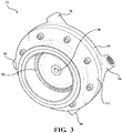
FIG. 4 is a top view of the turbine expander ofFIG. 2 with a turbine housing removed and the turbine blade and the shaft shown in phantom; -
FIG. 5 is a top view of the nozzle assembly ofFIGS. 2-4 , with the nozzle assembly including a nozzle block, a first nozzle component coupled to the nozzle block and defining a first nozzle shown in phantom, a second nozzle component coupled to the nozzle block and defining a second nozzle shown in phantom, a third nozzle component coupled to the nozzle block and defining a third nozzle shown in phantom, and a fourth nozzle component coupled to the nozzle block and defining a fourth nozzle shown in phantom; -
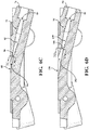
FIG.6A is a cross-sectional view of the first nozzle component taken along line 6A-6A ofFIG. 5 ; -
FIG. 6B is a cross-sectional view of the second nozzle component takenlong line 6B-6B ofFIG. 5 ; -
FIG. 6C is a cross-sectional view of the third nozzle component taken alongline 6C-6C ofFIG. 5 ; -
FIG. 6D is a cross-sectional view of the fourth nozzle component taken alongline 6D-6D ofFIG. 5 ; -
FIG. 7A is a cross-sectional view of a first throat section of the first nozzle taken alongline 7A-7A inFIG. 6A ; -
FIG. 7B is a cross-sectional view of a second throat section of the second nozzle taken alongline 7B-7B inFIG. 6B ; -
FIG. 7C is a cross-sectional view of a third throat section of the third nozzle taken alongline 7C-7C inFIG. 6C ; -
FIG. 7D is a cross-sectional view of a fourth throat section of the fourth nozzle taken alongline 7D-7D inFIG. 6D ; -
FIG. 8 is a perspective view of an alternative embodiment of the nozzle assembly ofFIGS. 2-5 with the nozzle block defining a first bore, a second bore, a third bore, and a fourth bore, with the first, second, third, and fourth nozzle components being removably coupled to the nozzle block, with the first, second, third, and fourth nozzles shown in phantom, and with the first, second, third, and fourth nozzle components disposed in the first, second, third, and fourth bores respectively; -
FIG. 9 is a perspective view of the nozzle assembly ofFIG. 8 with the first, second, third, and fourth nozzle components removed from the first, second, third, and fourth bores respectively; -
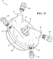
FIG. 10 is a perspective view of the turbine expander ofFIG. 2 further including a plurality of fluid couplers coupled to the first, second, third, and fourth nozzle components; -
FIG. 11 is a perspective view of the turbine expander ofFIG. 10 with the plurality of fluid coupled couplers removed from the first, second, third, and fourth nozzle components. - With reference to the Figures, wherein like numerals indicate like parts throughout the several views, a waste
heat recovery system 20 for recovering waste heat of an internal combustion engine (ICE) is schematically shown inFIG. 1 . The wasteheat recovery system 20 includes aturbine expander 22 for outputting power based on a working fluid, aflow control device 24 in fluid communication with theturbine expander 22, and acontroller 26 in communication with theflow control device 24. - With reference to
FIG. 3 , theturbine expander 22 includes aturbine blade 28 rotatable by the working fluid. As best shown inFIG. 2 , theturbine expander 22 also includes ashaft 30 coupled to and rotatable by theturbine blade 28. Theshaft 30 extends along a longitudinal axis A. The working fluid causes rotation of theturbine blade 28 about the longitudinal axis A of theshaft 30. - With continued reference to
FIG. 2 , theturbine expander 22 further includes anozzle assembly 32 for directing the working fluid to theturbine blade 28 for rotating theturbine blade 28. Thenozzle assembly 32 includes anozzle block 34 disposed about theshaft 30 and adjacent theturbine blade 28. Typically, thenozzle block 34 has an annular configuration. However, thenozzle block 34 may have any configuration suitable for directing the working fluid to theturbine blade 28. Thenozzle block 34 may have afirst face 36 facing theturbine blade 28, as best shown inFIG. 4 , and asecond face 38 facing opposite thefirst face 36, as best shown inFIG. 2 . - With continued reference to
FIG. 2 , thenozzle assembly 32 also includes anozzle component 40 coupled to thenozzle block 34 for accelerating the working fluid. As shown inFIGS. 5 and6A , thenozzle component 40 defines anozzle 42. In one embodiment, thenozzle component 40 is integral (i.e., one-piece) with thenozzle block 34, as shown inFIG. 2 . In another embodiment, as described in further detail below, thenozzle component 40 may be separate from (i.e., not integral with) thenozzle block 34. - The
nozzle 42 has a geometrical configuration. The geometrical configuration may be a converging-type configuration, a diverging-type configuration, or a de Laval (converging-diverging-type) configuration. Typically, the geometrical configuration is a de Laval configuration as shown inFIGS. 5 and6A . - As best shown in
FIG. 6A , when the geometrical configuration of thenozzle 42 is a de Laval configuration, thenozzle 42 may have a workingfluid inlet 44, a convergingsection 46, a divergingsection 48, athroat section 50 separating the convergingsection 46 from the divergingsection 48, and a workingfluid outlet 52. When present, the convergingsection 46 extends from the workingfluid inlet 44 to thethroat section 50. When the convergingsection 46 is present, the cross-sectional area of thenozzle 42 gradually decreases from the workingfluid inlet 44 to thethroat section 50. When present, the divergingsection 48 extends from thethroat section 50 to the workingfluid outlet 52. When the divergingsection 48 is present, the cross-sectional area of thenozzle 42 gradually increases from thethroat section 50 to the workingfluid outlet 52. When present, thethroat section 50 is where the cross-sectional area of thenozzle 42 is at a minimum. In the context of this disclosure, the minimum cross-sectional area of thenozzle 42 is referred to as the throatcross-sectional area 54, as best shown inFig 7A . - The working fluid passes through the converging
section 46 of thenozzle 42 to thethroat section 50. If the working fluid has a suitable pressure and mass flow rate, the working fluid velocity is choked at thethroat section 50. Whether the working fluid is of a suitable pressure and mass flow rate for the working fluid velocity to be choked at thethroat section 50 is based on the throatcross-sectional area 54. The working fluid is then expanded in the divergingsection 48 such that the working fluid velocity is increased to a supersonic velocity. In this manner, thenozzle 42 accelerates the working fluid to supersonic velocities. - As described above, the
nozzle component 40 may be integral with thenozzle block 34. In other embodiments, thenozzle component 40 may be fixed to thenozzle block 34, for example, by welding. As shown inFIGS. 8 and9 , thenozzle component 40 may be removably coupled to thenozzle block 34. When thenozzle component 40 is removably coupled to thenozzle block 34, thenozzle block 34 may define abore 56 for selectively receiving thenozzle component 40. In this manner, thenozzle component 40 may be selectively disposed in thebore 56. Advantageously, when thenozzle component 40 is removably coupled to thenozzle block 34, manufacturing complexity of the wasteheat recovery system 20 is reduced. Specifically, thenozzle 42 of thenozzle component 40 may be machined and/or cast independently of thenozzle block 34, thereby reducing manufacturing time and manufacturing costs. The removably couplednozzle component 40 also allows for greater customizability of the wasteheat recovery system 20 due to the interchangeability of thenozzle component 40. - When the
nozzle component 40 is removably coupled to thenozzle block 34, the nozzle component may include screw threads. Thenozzle block 34 may also include screw threads so that the nozzle component may be removably coupled to thenozzle block 34. In other embodiments, thenozzle component 40 may be removably coupled to thenozzle block 34 by a transition or interference fit. - In some embodiments, when the
nozzle component 40 is removably coupled to thenozzle block 34, at least a portion of thenozzle block 34 is disposed between thenozzle 42 and theturbine blade 28 as shown inFIGS. 8 and9 . In other embodiments, thenozzle block 34 is disposed entirely between thenozzle 42 and theturbine blade 28. In some embodiments, no portion of thenozzle block 34 is disposed between thenozzle 42 and theturbine blade 28. - The
nozzle component 40 may be further defined as afirst nozzle component 40, and thenozzle 42 may be further defined as afirst nozzle 42. Moreover, each section of thenozzle 42 described above may be further defined as a first section (e.g.first throat section 50, first throatcross-sectional area 54, etc.). - With reference to
FIG. 2 , thenozzle assembly 32 may also include asecond nozzle component 58 coupled to thenozzle block 34 for accelerating the working fluid. As shown inFIGS. 5 and6B , when present, thesecond nozzle component 58 defines asecond nozzle 60. In one embodiment, as best shown inFIG. 2 , thesecond nozzle component 58 is integral (i.e., one-piece) with thenozzle block 34. In another embodiment, as described in further detail below, thesecond nozzle component 58 may be separate from (i.e., not integral with) thenozzle block 34. - The
second nozzle 60 has a second geometrical configuration. The second geometrical configuration may be a converging-type configuration, a diverging-type configuration, or a de Laval (converging-diverging-type) configuration. Typically, the second geometrical configuration is a de Laval configuration as shown inFIGS. 5 and6B . When the second geometrical configuration is a de Laval configuration, thesecond nozzle 60 may have a second workingfluid inlet 62, a second convergingsection 64, a second divergingsection 66, asecond throat section 68 separating the second convergingsection 64 from the second divergingsection 66, and a second workingfluid outlet 70. As best seen inFIG. 7B , the minimum cross-sectional area of thesecond nozzle 60 is referred to as the second throatcross-sectional area 72. It is to be appreciated that the description of the first workingfluid inlet 44, the first convergingsection 46, the first divergingsection 48, thefirst throat section 50, and the first workingfluid outlet 52 also applies to the second workingfluid inlet 62, the second convergingsection 64, the second divergingsection 66, thesecond throat section 68, and the second workingfluid outlet 70. - In one embodiment, the second geometrical configuration of the
second nozzle 60, when present, is different from the first geometrical configuration of thefirst nozzle 42. In some embodiments, the first and second geometrical configurations may be different types of configurations. For example, the first geometrical configuration may be a converging-type configuration and the second geometrical configuration may be a de Laval configuration. In other embodiments, as shown inFIG. 5 , the first and second geometrical configurations may be the same type of configuration but have corresponding sections that differ from each other. For example, when the first and second geometrical configurations are de Laval configurations, at least one of the first workingfluid inlet 44, first convergingsection 46,first throat section 50, first divergingsection 48, and first workingfluid outlet 52 of thefirst nozzle 42 is different from the corresponding second workingfluid inlet 62, second convergingsection 64,second throat section 68, second divergingsection 66, and second workingfluid outlet 70 of thesecond nozzle 60. - In some embodiments, when the first and second geometrical configurations are de Laval configurations, the second throat
cross-sectional area 72 is different from the first throatcross-sectional area 54, as shown inFIGS. 7A and 7B . As described above, whether the velocity of the working fluid is choked at the first andsecond throat sections cross-sectional areas cross-sectional areas second nozzles second nozzles heat recovery system 20 may change the working fluid pressure and mass flow rate such that both the first andsecond nozzles second nozzles heat recovery system 20. Specifically, the first andsecond nozzles heat recovery system 20 may be operated at for a specific working fluid pressure. This advantageously allows the wasteheat recovery system 20 to retain maximum cycle efficiency and power output for a broader range of ICE operating states, as described in further detail below. - As shown in
FIG. 2 and described above, thesecond nozzle component 58 may be integral with thenozzle block 34. In other embodiments, thesecond nozzle component 58 may be fixed to thenozzle block 34, for example, by welding. As shown inFIGS. 8 and9 , in still other embodiments, thesecond nozzle component 58 may be removably coupled to thenozzle block 34. When thesecond nozzle component 58 is removably coupled to thenozzle block 34, the nozzle block may define asecond bore 74 for selectively receiving thesecond nozzle component 58. In this manner, thesecond nozzle component 58 may be selectively disposed in thesecond bore 74. - When the
second nozzle component 58 is removably coupled to thenozzle block 34, the second nozzle component may include screw threads. Thenozzle block 34 may also include screw threads so that thesecond nozzle component 58 may be removably coupled to thenozzle block 34. In other embodiments, thesecond nozzle component 58 may be removably coupled to thenozzle block 34 by a transition or interference fit. - In some embodiments, when the
second nozzle component 58 is removably coupled to thenozzle block 34, at least a portion of thenozzle block 34 is disposed between thesecond nozzle 60 and theturbine blade 28 as shown inFIGS. 8 and9 . In other embodiments, thenozzle block 34 is disposed entirely between thesecond nozzle 60 and theturbine blade 28. In some embodiments, no portion of thenozzle block 34 is disposed between thesecond nozzle 60 and theturbine blade 28. - In some embodiments, the first and
second nozzle components second nozzle components - With reference again to
FIG. 2 , thenozzle assembly 32 may also include athird nozzle component 76 coupled to thenozzle block 34 for accelerating the working fluid. When present, thethird nozzle component 76 defines athird nozzle 78. In one embodiment, as best shown inFIG. 2 , thethird nozzle component 76 is integral (i.e., one-piece) with thenozzle block 34. In another embodiment, as described in further detail below, thethird nozzle component 76 may be separate from (i.e., not integral with) thenozzle block 34. - The
third nozzle 78 has a third geometrical configuration. The third geometrical configuration may be a converging-type configuration, a diverging-type configuration, or a de Laval (converging-diverging-type) configuration. Typically, the third geometrical configuration is a de Laval configuration as shown inFIGS. 5 and6C . When the third geometrical configuration is a de Laval configuration, thethird nozzle 78 may have a third workingfluid inlet 80, a third convergingsection 82, a third divergingsection 84, athird throat section 86 separating the third convergingsection 82 from the third divergingsection 84, and a third workingfluid outlet 88. As shown inFIG. 7C , the minimum cross-sectional area of thethird nozzle 78 is referred to as the third throatcross-sectional area 90. It is to be appreciated that the description of the first workingfluid inlet 44, the first convergingsection 46, the first divergingsection 48, thefirst throat section 50, and the first workingfluid outlet 52 also applies to the third workingfluid inlet 80, the third convergingsection 82, the third divergingsection 84, thethird throat section 86, and the third workingfluid outlet 88. - The third geometrical configuration of the
third nozzle 78, when present, is different from at least one of the first and second geometrical configurations of the first andsecond nozzles FIG. 5 , the first, second, and third geometrical configurations may be the same type of configuration but have corresponding sections that differ from each other. For example, when the first, second, and third geometrical configurations are de Laval configurations, at least one of the third workingfluid inlet 80, third convergingsection 82, third divergingsection 84,third throat section 86, third diverging section 84and third workingfluid outlet 88 of thethird nozzle 78 is different from the corresponding first workingfluid inlet 44, first convergingsection 46, first divergingsection 48,first throat section 50, and first workingfluid outlet 52 of thefirst nozzle 42 and/or the second workingfluid inlet 62, second convergingsection 64, second divergingsection 66,second throat section 68, and second workingfluid outlet 70 of thesecond nozzle 60. - In some embodiments, when the first, second, and third geometrical configurations are de Laval configurations, the third throat
cross-sectional area 90 is different from at least one of first and second throatcross-sectional areas cross-sectional areas FIGS. 7A-C . - When the geometrical configurations of the nozzles are different from each other, the number of combinations of nozzles that the working fluid may pass through prior to rotating the
turbine blade 28 is 2 n - 1, wherein n is the number of nozzles included in thenozzle assembly 32. - When the first, second, and third geometrical configurations are different from each other, the working fluid my pass through seven different combinations of the first, second, and
third nozzles turbine blade 28 based on the working fluid pressure and mass flow rate. Specifically, the working fluid may pass through thefirst nozzle 42 alone, thesecond nozzle 60 alone, thethird nozzle 78 alone, the first andsecond nozzles third nozzles third nozzles third nozzles - When the first, second, and third geometrical configurations are de Laval configurations and the first, second, and third throat
cross-sectional areas third throat sections cross-sectional areas cross-sectional areas third nozzles third nozzles heat recovery system 20 may change the working fluid pressure and mass flow rate such that different combinations of the first, second, andthird nozzles third nozzles heat recovery system 20. Specifically, the first, second, andthird nozzles heat recovery system 20 may be operated at for a specific working fluid pressure. This advantageously allows the wasteheat recovery system 20 to retain maximum cycle efficiency and power output for a broader range of ICE operating states, as described in further detail below. - As shown in
FIG. 2 and described above, thethird nozzle component 76 may be integral with thenozzle block 34. In other embodiments, thethird nozzle component 76 may be fixed to thenozzle block 34, for example, by welding. As shown inFIGS. 8 and9 , in still other embodiments, thethird nozzle component 76 may be removably coupled to thenozzle block 34. When thethird nozzle component 76 is removably coupled to thenozzle block 34, the nozzle block may define athird bore 92 for selectively receiving thethird nozzle component 76. In this manner, thethird nozzle component 76 may be selectively disposed in thethird bore 92. - When the
third nozzle component 76 is removably coupled to thenozzle block 34, thethird nozzle component 76 may include screw threads. Thenozzle block 34 may also include screw threads so that thethird nozzle component 76 may be removably coupled to thenozzle block 34. In other embodiments, thethird nozzle component 76 may be removably coupled to thenozzle block 34 by a transition or interference fit. - In some embodiments, when the
third nozzle component 76 is removably coupled to thenozzle block 34, at least a portion of thenozzle block 34 is disposed between thethird nozzle 78 and theturbine blade 28 as shown inFIGS. 8 and9 . In other embodiments, thenozzle block 34 is disposed entirely between thethird nozzle 78 and theturbine blade 28. In some embodiments, no portion of thenozzle block 34 is disposed between thethird nozzle 78 and theturbine blade 28. - In some embodiments, the first, second, and
third nozzle components third nozzle components - With reference again to
FIG. 2 , thenozzle assembly 32 may also include afourth nozzle component 94 coupled to thenozzle block 34 for accelerating the working fluid. When present, thefourth nozzle component 94 defines afourth nozzle 96. In one embodiment, as best shown inFIG. 2 , thefourth nozzle component 94 is integral (i.e., one-piece) with thenozzle block 34. In another embodiment, as described in further detail below, thefourth nozzle component 94 may be separate from (i.e., not integral with) thenozzle block 34. - The
fourth nozzle 96 has a fourth geometrical configuration. The fourth geometrical configuration may be a converging-type configuration, a diverging-type configuration, or a de Laval (converging-diverging-type) configuration. Typically, the fourth geometrical configuration is a de Laval configuration as shown inFIGS. 5 and6D . When the fourth geometrical configuration is a de Laval configuration, thefourth nozzle 96 may have a fourth workingfluid inlet 98, a fourth convergingsection 100, a fourth divergingsection 102, afourth throat section 104 separating the fourth convergingsection 100 from the fourth divergingsection 102, and a fourth workingfluid outlet 106. As shown inFIG. 7C , the minimum cross-sectional area of thefourth nozzle 96 is referred to as the fourth throatcross-sectional area 108. It is to be appreciated that the description of the first workingfluid inlet 44, the first convergingsection 46, the first divergingsection 48, thefirst throat section 50, and the first workingfluid outlet 52 also applies to the fourth workingfluid inlet 98, the fourth convergingsection 100, the fourth divergingsection 102, thefourth throat section 104, and the fourth workingfluid outlet 106. - The fourth geometrical configuration of the
fourth nozzle 96, when present, is different from at least one of the first, second, and third geometrical configurations of the first, second, andthird nozzles FIG. 5 , the first, second, third geometrical, and fourth configurations may be the same type of configuration but have corresponding sections that differ from each other. For example, when the first, second, third, and fourth geometrical configurations are de Laval configurations, at least one of the fourth workingfluid inlet 98, fourth convergingsection 100, fourth divergingsection 102,fourth throat section 104, and fourth workingfluid outlet 106 of thefourth nozzle 96 is different from the corresponding first workingfluid inlet 44, first convergingsection 46, first divergingsection 48,first throat section 50, and first workingfluid outlet 52 of thefirst nozzle 42, the second workingfluid inlet 62, second convergingsection 64, second divergingsection 66,second throat section 68, and second workingfluid outlet 70 of thesecond nozzle 60, and/or the third workingfluid inlet 80, third convergingsection 82, third divergingsection 84,third throat section 86, and third workingfluid outlet 88 of thethird nozzle 78. - In some embodiments, when the first, second, third, and fourth geometrical configurations are de Laval configurations, the fourth throat
cross-sectional area 108 is different from at least one of first, second, and third throatcross-sectional areas cross-sectional areas FIGS. 7A-D . - When the first, second, third, and fourth geometrical configurations are different from each other, the working fluid my pass through fifteen different combinations of the first, second, third, and
fourth nozzles turbine blade 28 based on the working fluid pressure and mass flow rate. Specifically, the working fluid may pass through thefirst nozzle 42 alone, thesecond nozzle 60 alone, thethird nozzle 78 alone, thefourth nozzle 96 alone, the first and second nozzles alone 42, 60, the first and third nozzles alone 42, 78, the first andfourth nozzles fourth nozzles third nozzles fourth nozzles fourth nozzles fourth nozzles fourth nozzles - When the first, second, third, and fourth geometrical configurations are de Laval configurations and the first, second, third, and fourth throat
cross-sectional areas fourth throat sections cross-sectional areas cross-sectional areas fourth nozzles fourth nozzles heat recovery system 20 may change the working fluid pressure and mass flow rate such that different combinations of the first, second, third, andfourth nozzles fourth nozzles heat recovery system 20. Specifically, the first, second, third, andfourth nozzles heat recovery system 20 may be operated at for a specific working fluid pressure. This advantageously allows the wasteheat recovery system 20 to retain maximum cycle efficiency and power output for a broader range of ICE operating states, as described in further detail below. - As shown in
FIG. 2 and described above, thefourth nozzle component 94 may be integral with thenozzle block 34. In other embodiments, thefourth nozzle component 94 may be fixed to thenozzle block 34, for example, by welding. As shown inFIGS. 8 and9 , in still other embodiments, thethird nozzle component 76 may be removably coupled to thenozzle block 34. When thefourth nozzle component 94 is removably coupled to thenozzle block 34, thenozzle block 34 may define afourth bore 110 for selectively receiving thethird nozzle component 76. In this manner, thefourth nozzle component 94 may be selectively disposed in thefourth bore 110. - When the
fourth nozzle component 94 is removably coupled to thenozzle block 34, thefourth nozzle component 94 may include screw threads. Thenozzle block 34 may also include screw threads so that thefourth nozzle component 94 may be removably coupled to thenozzle block 34. In other embodiments, thefourth nozzle component 94 may be removably coupled to thenozzle block 34 by a transition or interference fit. - In some embodiments, when the
fourth nozzle component 94 is removably coupled to thenozzle block 34, at least a portion of thenozzle block 34 is disposed between thefourth nozzle 96 and theturbine blade 28 as shown inFIGS. 8 and9 . In other embodiments, thenozzle block 34 is disposed entirely between thefourth nozzle 96 and theturbine blade 28. In some embodiments, no portion of thenozzle block 34 is disposed between thefourth nozzle 96 and theturbine blade 28. - In some embodiments, the first, second, third nozzle, and
fourth nozzle components FIG. 4 , the first, second, third, andfourth nozzle components - It is to be appreciated that the
nozzle assembly 32 may further include any number of additional nozzle components and that the description regarding thefirst nozzle component 40 is applicable to any additional nozzle component. It is to be further appreciated that any geometrical configuration of any nozzle defined by the additional nozzle components will be different from at least one of the nozzles included in the nozzle assembly. In this manner, the operating range of the wasteheat recovery system 20 can be expanded even further by the inclusion of additional nozzle components beyond the first, second, third, and/orfourth nozzle components nozzle assembly 32 may include five, six, seven, or eight nozzle components. However, it is to be appreciated that thenozzle assembly 32 may have more than eight nozzle components. - As shown in
FIGS. 2 and3 , theturbine expander 22 may include aturbine housing 112. When theturbine housing 112 is present, theturbine blade 28 may be disposed in theturbine housing 112. - With reference again to
FIG. 1 , the wasteheat recovery system 20 includes theflow control device 24 in fluid communication with theturbine expander 22 for directing the working fluid to at least one of the first, second, third, and/orfourth nozzles turbine expander 22, or to bypass theturbine expander 22. Theflow control device 24 may be a valve, or any other suitable working fluid flow control device. Theflow control device 24 is typically disposed upstream of theturbine expander 22. - In some embodiments, the
flow control device 24 may include a plurality of valves corresponding to each nozzle included in theturbine expander 22. For example, if theturbine expander 22 includes two nozzles, theflow control device 24 includes two valves. Each valve may be movable between an open position where the working fluid can flow to the corresponding nozzle, and a closed position where the working fluid is restricted from flowing to the corresponding nozzle. When theflow control device 24 includes a plurality of valves corresponding to each nozzle included in the turbine expander, theflow control device 24 may also include a bypass valve that causes the working fluid to bypass theturbine expander 22. In other embodiments, the flow control device may include a switching valve adapted to selectively direct working fluid to one or more of the nozzles included in theturbine expander 22, or to bypass theturbine expander 22. It is to be appreciated that any valves of theflow control device 24 may be movable between a closed position, an open position, and an intermediate position in which flow of the working fluid is metered. - With continued reference to
Fig. 1 , the wasteheat recovery system 20 includes thecontroller 26 in communication with theflow control device 24 and adapted to control theflow control device 24 to direct the working fluid to at least one of the first, second, third, and/orfourth nozzles turbine expander 22, or to bypass theturbine expander 22. - The
controller 26 may include one or more processors, or microprocessors, for processing instructions stored in memory to control operation of theflow control device 24. Such instructions may be any of the functions, algorithms or techniques described herein performed by thecontroller 26. Additionally or alternatively, thecontroller 26 may comprise one or more microcontrollers, field programmable gate arrays, systems on a chip, discrete circuitry, and/or other suitable hardware, software, or firmware that is capable of carrying out the functions described herein. - Typically, the working fluid is an organic, high molecular mass working fluid with a liquid-vapor phase change occurring at a lower temperature than a water-steam phase change. The working fluid may include at least one of ethanol, methanol, kerosene, gasoline, diesel, propanol, butanol, water, benzene, toluene, methane, ethane, propane, butane, acetone, or liquid hydrogen. During operation of the waste heat recovery system, the working fluid is in one of a liquid state or a vapor state. In the vapor state, the working fluid is more suitable for rotating the turbine blade.
- As shown in
FIG. 1 , the wasteheat recovery system 20 may also include anevaporator 114 in fluid communication with theflow control device 24 and theturbine expander 22. Theevaporator 114 transfers heat discarded by the ICE to the working fluid, thereby causing the working fluid to phase change from the liquid state to the vapor state. When present, theevaporator 114 is disposed upstream of theflow control device 24. - The waste
heat recovery system 20 may also include acondenser 116 in fluid communication with theturbine expander 22 and theflow control device 24. Thecondenser 116 condenses the working fluid from the vapor state to the liquid state after the working fluid passes through theturbine expander 22. Thecondenser 116 is disposed downstream of theturbine expander 22. In some embodiments, when the wasteheat recovery system 20 includes theevaporator 114, thecondenser 116 is disposed downstream of theturbine expander 22 and upstream of theevaporator 114. - The waste
heat recovery system 20 may further include at least onesensor 118 in communication with thecontroller 26. The at least onesensor 118 is adapted to detect a characteristic of the working fluid. When present, the at least onesensor 118 is disposed upstream of theflow control device 24 and theturbine expander 22 such that the at least onesensor 118 may detect the characteristic of the working fluid prior to the working fluid passing through theflow control device 24. As shown inFIG. 1 , when theevaporator 114 is included in the wasteheat recovery system 20, the at least onesensor 118 is disposed upstream of theflow control device 24 and downstream of theevaporator 114. However, the at least onesensor 118 may be disposed upstream of theevaporator 114 or at any other location suitable for detecting the characteristic of the working fluid. The at least onesensor 118 is further adapted to send a signal to thecontroller 26 indicative of the characteristic of the working fluid detected by the at least onesensor 118. The characteristic of the working fluid detected by the at least onesensor 118 may be the working fluid pressure, the working fluid mass flow rate, the working fluid temperature, working fluid quality, and combinations thereof. In some embodiments, the at least onesensor 118 detects the working fluid temperature and the working fluid pressure. - In some embodiments the at least one
sensor 118 may be two sensors. When the at least onesensor 118 is two sensors, each sensor may detect one of the characteristics of the working fluid described above. Alternatively, each sensor may detect a combination of the characteristics of the working fluid described above. In some embodiments, one sensor detects working fluid temperature and the other sensor detects working fluid pressure. - To ensure maximum cycle efficiency and power output of the waste
heat recovery system 20, the combination of first, second, third, and/orfourth nozzles turbine blade 28 is based on a function of the working fluid pressure and working fluid mass flow rate. As described above, heat discarded by the ICE is recovered by the wasteheat recovery system 20 to heat the working fluid so that the working fluid undergoes liquid-vapor phase change. Heat discarded by the ICE varies based on the speed and load (i.e., operating state) of the ICE. As such, at certain operating states of the ICE (e.g. start-up, acceleration, etc.), heat discarded by the ICE and recovered by the wasteheat recovery system 20 may render the working fluid pressure unsuitable for one or more of the first, second, third, and/orfourth nozzles heat recovery system 20 is to be maintained. As will be described below, the at least onesensor 118 communicates with thecontroller 26 to direct fluid to at least one of the first, second, third, and/orfourth nozzles turbine expander 22 to ensure maximum cycle efficiency and power output of the wasteheat recovery system 20 across a broader range of operating states of the ICE. - When the at least one
sensor 118 is included in the wasteheat recovery system 20, thecontroller 26 may be adapted to control theflow control device 24 to direct the working fluid to at least one of the first, second, third, and/orfourth nozzles turbine expander 22 or to bypass theturbine expander 22 based on the characteristic of the working fluid detected by the at least onesensor 118. In one embodiment, when thecontroller 26 receives the signal indicative of the characteristic of the working fluid detected by the at least onesensor 118, thecontroller 26 may compare the detected characteristic of the working fluid with a threshold value corresponding to the geometrical configuration of each of the first, second, third, and/orfourth nozzles flow control device 24 to direct the working fluid to each of the first, second, third, and/orfourth nozzles controller 26 determines that no corresponding threshold value(s) is(are) exceeded by the detected characteristic of the working fluid, then thecontroller 26 controls theflow control device 24 to direct the working fluid to bypass theturbine expander 22. In this manner, the different geometrical configurations of the first, second, third, and/orfourth nozzles heat recovery system 20 by accelerating the working fluid to supersonic velocities at a broader range of working fluid pressures, mass flow rates, temperatures, etc. Moreover, as the working fluid pressure and/or mass flow rate varies during operation of the ICE, the wasteheat recovery system 20 advantageously allows for an incremental increase of working fluid flow to theturbine blade 28. - For example, during start-up of the ICE, the working fluid mass flow rate may be low to ensure maximum transfer of heat discarded by the ICE to the working fluid. To ensure maximum cycle efficiency and power output of the waste
heat recovery system 20, the working fluid pressure will typically have a higher value than when the engine is in other operating states, such as a steady state operating state. Based on the higher value of the working fluid pressure, thecontroller 26 will control theflow control device 24 to direct the working fluid to at least one of the first, second, third, and/orfourth nozzles - In another example, during acceleration, heat discarded by the ICE is constantly varying. To ensure maximum cycle efficiency and power output of the waste
heat recovery system 20, thecontroller 26 may control theflow control device 24 to direct the working fluid to one, two three, and/or four of the first, second, third, and/orfourth nozzles - In some embodiments, the at least one
sensor 118 may be adapted to detect at least one of a working fluid temperature and a working fluid pressure of the working fluid upstream of theturbine expander 22. Thecontroller 26 my control theflow control device 24 to direct the working fluid to at least one of the first, second, third, and/orfourth nozzles turbine expander 22 or to bypass theturbine expander 22 based on at least one of the working fluid mass flow rate and the working fluid pressure detected by the at least onesensor 118. - With reference again to
FIG. 1 , the wasteheat recovery system 20 may also include a workingfluid circuit 120 for circulating the working fluid. The workingfluid circuit 120 fluidly couples theturbine expander 22, theflow control device 24, theevaporator 114, and/or thecondenser 116. The workingfluid circuit 120 may include a plurality of fluid conduits. - As shown in
FIGS. 10 and11 , when the workingfluid circuit 120 includes a plurality of fluid conduits, theturbine expander 22 may include one or morefluid couplers 122 to removably couple one of the fluid conduits to each of the first, second, third, and/orfourth nozzle components turbine expander 22. - In some embodiments, the working
fluid circuit 120 may include a bypass loop that fluidly couples theflow control device 24 to thecondenser 116 directly, thereby circumventing passage of the working fluid through theturbine expander 22. - With reference again to
FIG. 1 , the wasteheat recovery system 20 may also include apump 124 adapted to adjust the working fluid flow rate through the wasteheat recovery system 20 at one or more speeds. Thepump 124 may be any suitable pump, such as a piston pump or a diaphragm pump. In some embodiments, when the wasteheat recovery system 20 includes theevaporator 114 and thecondenser 116, thepump 124 may disposed upstream of theevaporator 114 and downstream of thecondenser 116. In some embodiments, when the at least onesensor 118 is present, thepump 124 may be in communication with thecontroller 26 and thecontroller 26 may control thepump 124 to adjust the working fluid flow rate based on the characteristic of the working fluid detected by the at least onesensor 118. - A vehicle may include the waste
heat recovery system 20 as described herein. In some embodiments, theshaft 30 of theturbine expander 22 may be coupled to a generator. When theshaft 30 is coupled to the generator, waste heat generated by the ICE may be converted to electric power that may be stored or used by the vehicle. - The invention has been described in an illustrative manner, and it is to be understood that the terminology which has been used is intended to be in the nature of words of description rather than of limitation. Many modifications and variations of the present invention are possible in light of the above teachings, and the invention may be practiced otherwise than as specifically described.
Claims (15)
- A turbine expander for a waste heat recovery system for outputting power based on a working fluid, said turbine expander comprising:a turbine blade rotatable by the working fluid;a shaft coupled to and rotatable by said turbine blade, with said shaft extending along a longitudinal axis; anda nozzle assembly for directing the working fluid to said turbine blade for rotating said turbine blade, said nozzle assembly comprising,a nozzle block disposed about said shaft and adjacent said turbine blade,a first nozzle component coupled to said nozzle block for accelerating the working fluid, with said nozzle component defining a first nozzle having a first geometrical configuration, anda second nozzle component coupled to said nozzle block for accelerating the working fluid, with said second nozzle component defining a second nozzle having a second geometrical configuration that is different from said first geometrical configuration.
- The turbine expander as set forth in claim 1, wherein said first geometrical configuration of said first nozzle is a de Laval configuration having a first throat cross-sectional area, and wherein said second geometrical configuration of said second nozzle is a de Laval configuration having a second throat cross-sectional area that is different from said first throat cross-sectional area.
- The turbine expander as set forth in any one of claims 1 and 2, wherein said nozzle assembly further comprises a third nozzle component coupled to said nozzle block for accelerating the working fluid, with said third nozzle component defining a third nozzle having a third geometrical configuration that is different from at least one of said first and second geometrical configurations.
- The turbine expander as set forth in claim 3, wherein said nozzle assembly further comprises a fourth nozzle component coupled to said nozzle block for accelerating the working fluid, with said fourth nozzle component defining a fourth nozzle having a fourth geometrical configuration that is different from at least one of said first, second geometrical configuration, and third geometrical configurations.
- The turbine expander as set forth in claim 4, wherein said first geometrical configuration of said first nozzle is a de Laval configuration having a first throat cross-sectional area, wherein said second geometrical configuration of said second nozzle is a de Laval configuration having a second throat cross-sectional area, wherein said third geometrical configuration of said third nozzle is a de Laval configuration having a third throat cross-sectional area, and wherein said fourth geometrical configuration is a de Laval configuration having a fourth throat cross-sectional area, and wherein each of said first, second, third, and fourth throat cross-sectional areas are different.
- The turbine expander as set forth in any one of claims 1-5, wherein said first and second nozzle components are spaced circumferentially about said longitudinal axis.
- The turbine expander as set forth in any one of claims 5 and 6, wherein said first, second, third, and fourth nozzle components are spaced circumferentially about said longitudinal axis.
- The turbine expander as set forth in any one of claims 1-7, wherein said first and second nozzle components are integral with said nozzle block.
- The turbine expander as set forth in any one of claims 1-8, wherein said nozzle block further defines a first bore and a second bore, wherein said first nozzle component is removably coupled to said nozzle block such that said first nozzle component is selectively disposed in said first bore, and wherein said second nozzle component is removably coupled to said nozzle block such that said second nozzle component is selectively disposed in said second bore.
- A waste heat recovery system for recovering waste heat of an internal combustion engine, said waste heat recovery system comprising:said turbine expander as set forth in any one of the preceding claims;a flow control device in fluid communication with said turbine expander for directing the working fluid to at least one of said first and second nozzles or to bypass said turbine expander; anda controller in communication with said flow control device and adapted to control said flow control device to direct the working fluid to at least one of said first and second nozzles or to bypass said turbine expander.
- The waste heat recovery system as set forth in claim 10 further comprising at least one sensor adapted to detect at least one of a working fluid temperature and a working fluid pressure of the working fluid upstream of said turbine expander.
- The waste heat recovery system as set forth in claim 11, wherein said controller controls said flow control device to direct the working fluid to at least one of said first and second nozzles or to bypass said turbine expander based on at least one of said working fluid temperature and said working fluid pressure detected by said at least one sensor.
- A turbine expander for a waste heat recovery system for outputting power based on a working fluid, said turbine expander comprising:a turbine blade rotatable by the working fluid;a shaft coupled to and rotatable by said turbine blade; anda nozzle assembly for directing the working fluid to said turbine blade for rotating said turbine blade, said nozzle assembly comprising,a nozzle block disposed about said shaft and adjacent said turbine blade, with said nozzle block defining a bore, anda nozzle component removably coupled to said nozzle block such that said nozzle component is selectively disposed in said bore for accelerating the working fluid, with said nozzle component defining a nozzle;wherein at least a portion of said nozzle block is disposed between said nozzle and said turbine blade.
- A waste heat recovery system for recovering waste heat of an internal combustion engine, said waste heat recovery system comprising:a turbine expander for outputting power based on a working fluid, said turbine expander comprising,a turbine blade rotatable by the working fluid,a shaft coupled to and rotatable by said turbine blade, with said shaft extending along a longitudinal axis, anda nozzle assembly for directing the working fluid to said turbine blade for rotating said turbine blade, said nozzle assembly comprising,a nozzle block disposed about said shaft and adjacent said turbine blade, with said nozzle block defining a bore, anda nozzle component removably coupled to said nozzle block such that said nozzle component is selectively disposed in said bore for accelerating the working fluid, with said nozzle component defining a nozzle;a flow control device in fluid communication with said turbine expander for directing the working fluid to said nozzle or to bypass said turbine expander; anda controller in communication with said flow control device and adapted to control said flow control device to direct the working fluid to said nozzle or to bypass said turbine expander.
- The waste heat recovery system as set forth in claim 14, wherein at least a portion of said nozzle block is disposed between said nozzle and said turbine blade.
Priority Applications (1)
| Application Number | Priority Date | Filing Date | Title |
|---|---|---|---|
| EP23175227.0A EP4219930A1 (en) | 2018-02-27 | 2019-02-26 | Waste heat recovery system and turbine expander for the same |
Applications Claiming Priority (1)
| Application Number | Priority Date | Filing Date | Title |
|---|---|---|---|
| US201862635858P | 2018-02-27 | 2018-02-27 |
Related Child Applications (2)
| Application Number | Title | Priority Date | Filing Date |
|---|---|---|---|
| EP23175227.0A Division EP4219930A1 (en) | 2018-02-27 | 2019-02-26 | Waste heat recovery system and turbine expander for the same |
| EP23175227.0A Division-Into EP4219930A1 (en) | 2018-02-27 | 2019-02-26 | Waste heat recovery system and turbine expander for the same |
Publications (2)
| Publication Number | Publication Date |
|---|---|
| EP3530924A1 true EP3530924A1 (en) | 2019-08-28 |
| EP3530924B1 EP3530924B1 (en) | 2023-06-28 |
Family
ID=65598586
Family Applications (2)
| Application Number | Title | Priority Date | Filing Date |
|---|---|---|---|
| EP23175227.0A Pending EP4219930A1 (en) | 2018-02-27 | 2019-02-26 | Waste heat recovery system and turbine expander for the same |
| EP19159512.3A Active EP3530924B1 (en) | 2018-02-27 | 2019-02-26 | Waste heat recovery system and turbine expander for the same |
Family Applications Before (1)
| Application Number | Title | Priority Date | Filing Date |
|---|---|---|---|
| EP23175227.0A Pending EP4219930A1 (en) | 2018-02-27 | 2019-02-26 | Waste heat recovery system and turbine expander for the same |
Country Status (5)
| Country | Link |
|---|---|
| US (2) | US11156152B2 (en) |
| EP (2) | EP4219930A1 (en) |
| JP (2) | JP2019152206A (en) |
| KR (1) | KR20190103059A (en) |
| CN (3) | CN116641760A (en) |
Cited By (1)
| Publication number | Priority date | Publication date | Assignee | Title |
|---|---|---|---|---|
| WO2022023053A1 (en) | 2020-07-29 | 2022-02-03 | IFP Energies Nouvelles | Organic rankine cycle axial turbine with controlled variable intake |
Families Citing this family (3)
| Publication number | Priority date | Publication date | Assignee | Title |
|---|---|---|---|---|
| US11156152B2 (en) * | 2018-02-27 | 2021-10-26 | Borgwarner Inc. | Waste heat recovery system with nozzle block including geometrically different nozzles and turbine expander for the same |
| US20210079799A1 (en) * | 2019-09-12 | 2021-03-18 | General Electric Company | Nozzle assembly for turbine engine |
| US11015489B1 (en) * | 2020-03-20 | 2021-05-25 | Borgwarner Inc. | Turbine waste heat recovery expander with passive method for system flow control |
Citations (5)
| Publication number | Priority date | Publication date | Assignee | Title |
|---|---|---|---|---|
| FR331950A (en) * | 1903-05-12 | 1903-10-08 | Eschraenkter Haftung | Injection device for steam turbines with variable number of turns |
| FR344683A (en) * | 1904-04-21 | 1904-11-10 | Elling Compressor C As | Improvements to fractional injection gas and steam turbines |
| US4097188A (en) * | 1976-04-15 | 1978-06-27 | Terence Owen Forster | Nozzle insert for a turbine |
| US6416277B1 (en) * | 1998-11-05 | 2002-07-09 | Elliott Turbomachinery Co., Inc. | Individually replaceable and reversible insertable steam turbine nozzle |
| US20130205783A1 (en) * | 2010-10-13 | 2013-08-15 | Robert Bosch Gmbh | Steam turbine |
Family Cites Families (24)
| Publication number | Priority date | Publication date | Assignee | Title |
|---|---|---|---|---|
| US700744A (en) * | 1898-01-12 | 1902-05-27 | Curtis Steam Turbine Company | Elastic-fluid turbine. |
| FR318433A (en) * | 1902-02-05 | 1902-10-16 | Laval Soc D | Improvements to steam turbines |
| US740332A (en) * | 1903-04-03 | 1903-09-29 | Johann Stumpf | Steam-turbine. |
| US1985404A (en) * | 1933-01-23 | 1934-12-25 | Murray Iron Works Company | Means for regulating a steam turbine |
| CH507446A (en) * | 1968-12-03 | 1971-05-15 | Siemens Ag | Arrangement for live steam supply for steam turbines |
| DE1910200A1 (en) * | 1969-02-28 | 1970-09-17 | Siemens Ag | Method for fastening the nozzles to turbine housing parts and nozzle fastening arrangement produced thereafter |
| US4066381A (en) * | 1976-07-19 | 1978-01-03 | Hydragon Corporation | Turbine stator nozzles |
| US4325670A (en) | 1980-08-27 | 1982-04-20 | Westinghouse Electric Corp. | Method for admitting steam into a steam turbine |
| CH654625A5 (en) * | 1981-11-30 | 1986-02-28 | Bbc Brown Boveri & Cie | INLET HOUSING OF A STEAM TURBINE. |
| DE4214773A1 (en) | 1992-05-04 | 1993-11-11 | Abb Patent Gmbh | Steam turbine with a rotary valve to control the steam throughput |
| US7644585B2 (en) | 2004-08-31 | 2010-01-12 | The United States Of America As Represented By The Administrator Of The U.S. Environmental Protection Agency | Multi-stage turbocharging system with efficient bypass |
| CN101091041A (en) * | 2004-08-31 | 2007-12-19 | 美国环境保护署 | Efficient bypass valve for multi-stage turbocharging system |
| DE102008012907A1 (en) | 2008-03-06 | 2009-09-10 | Daimler Ag | Method for obtaining energy from an exhaust gas stream and motor vehicle |
| EP2157287A1 (en) * | 2008-08-22 | 2010-02-24 | ALSTOM Technology Ltd | Multifrequency control stage for improved dampening of excitation factors |
| DE102009045380A1 (en) | 2009-10-06 | 2011-04-07 | Robert Bosch Gmbh | driving means |
| DE102009055180A1 (en) | 2009-12-22 | 2011-06-30 | Robert Bosch GmbH, 70469 | Laval |
| DE102010001118B4 (en) * | 2010-01-22 | 2021-05-12 | Robert Bosch Gmbh | Method for operating an internal combustion engine with a steam power plant |
| RU2012124190A (en) | 2012-06-09 | 2013-12-20 | Владимир Николаевич Костюков | MULTI-STAGE TURBO MACHINE |
| DE102012211578B4 (en) | 2012-07-04 | 2015-02-19 | Bmw Ag | Device and method for using waste heat of an internal combustion engine, in particular of a motor vehicle, as well as a turbine for such a device |
| JP2014206085A (en) * | 2013-04-12 | 2014-10-30 | 三菱重工業株式会社 | Axial flow turbine |
| DE102013218887A1 (en) | 2013-09-20 | 2015-03-26 | Mahle International Gmbh | Laval |
| US9909461B2 (en) | 2015-11-19 | 2018-03-06 | Borgwarner Inc. | Waste heat recovery system |
| US11156152B2 (en) | 2018-02-27 | 2021-10-26 | Borgwarner Inc. | Waste heat recovery system with nozzle block including geometrically different nozzles and turbine expander for the same |
| US11015489B1 (en) * | 2020-03-20 | 2021-05-25 | Borgwarner Inc. | Turbine waste heat recovery expander with passive method for system flow control |
-
2019
- 2019-02-22 US US16/282,854 patent/US11156152B2/en active Active
- 2019-02-25 JP JP2019031418A patent/JP2019152206A/en active Pending
- 2019-02-26 EP EP23175227.0A patent/EP4219930A1/en active Pending
- 2019-02-26 EP EP19159512.3A patent/EP3530924B1/en active Active
- 2019-02-27 CN CN202310623118.9A patent/CN116641760A/en active Pending
- 2019-02-27 KR KR1020190023218A patent/KR20190103059A/en not_active Application Discontinuation
- 2019-02-27 CN CN201910144972.0A patent/CN110195616B/en active Active
- 2019-02-27 CN CN201920246353.8U patent/CN210122923U/en active Active
-
2021
- 2021-09-29 US US17/488,549 patent/US11560833B2/en active Active
-
2023
- 2023-11-30 JP JP2023203246A patent/JP2024020597A/en active Pending
Patent Citations (5)
| Publication number | Priority date | Publication date | Assignee | Title |
|---|---|---|---|---|
| FR331950A (en) * | 1903-05-12 | 1903-10-08 | Eschraenkter Haftung | Injection device for steam turbines with variable number of turns |
| FR344683A (en) * | 1904-04-21 | 1904-11-10 | Elling Compressor C As | Improvements to fractional injection gas and steam turbines |
| US4097188A (en) * | 1976-04-15 | 1978-06-27 | Terence Owen Forster | Nozzle insert for a turbine |
| US6416277B1 (en) * | 1998-11-05 | 2002-07-09 | Elliott Turbomachinery Co., Inc. | Individually replaceable and reversible insertable steam turbine nozzle |
| US20130205783A1 (en) * | 2010-10-13 | 2013-08-15 | Robert Bosch Gmbh | Steam turbine |
Cited By (2)
| Publication number | Priority date | Publication date | Assignee | Title |
|---|---|---|---|---|
| WO2022023053A1 (en) | 2020-07-29 | 2022-02-03 | IFP Energies Nouvelles | Organic rankine cycle axial turbine with controlled variable intake |
| FR3113090A1 (en) | 2020-07-29 | 2022-02-04 | IFP Energies Nouvelles | ORC axial turbine with controlled variable inlet |
Also Published As
| Publication number | Publication date |
|---|---|
| JP2019152206A (en) | 2019-09-12 |
| JP2024020597A (en) | 2024-02-14 |
| CN110195616B (en) | 2023-05-30 |
| EP4219930A1 (en) | 2023-08-02 |
| US20220018281A1 (en) | 2022-01-20 |
| US20190264606A1 (en) | 2019-08-29 |
| US11560833B2 (en) | 2023-01-24 |
| US11156152B2 (en) | 2021-10-26 |
| EP3530924B1 (en) | 2023-06-28 |
| CN116641760A (en) | 2023-08-25 |
| CN110195616A (en) | 2019-09-03 |
| KR20190103059A (en) | 2019-09-04 |
| CN210122923U (en) | 2020-03-03 |
Similar Documents
| Publication | Publication Date | Title |
|---|---|---|
| US11560833B2 (en) | Waste heat recovery system with nozzle block including geometrically different nozzles and turbine expander for the same | |
| US10294825B2 (en) | Waste-heat utilization assembly of an internal combustion engine and method for operating a waste-heat utilization assembly | |
| US10125690B2 (en) | Method and system for starting up an aircraft turbomachine | |
| EP2676007B1 (en) | Abnormality detection apparatus and abnormality detection method for rankine cycle system | |
| JPH05263662A (en) | Tip clearance control apparatus for turbo machine and blade | |
| JP6157733B2 (en) | Internal combustion engine arrangement with waste heat recovery system and control process of waste heat recovery system | |
| JP5829409B2 (en) | Waste heat utilization system for automobiles | |
| WO2015052837A1 (en) | Engine system provided with intake bypass device | |
| JP2010180781A (en) | Control device for internal combustion engine with supercharger | |
| JP2019173647A (en) | Turbo-type supercharge system and control method of turbo-type supercharge system | |
| JP2012523545A (en) | How to detect a frozen state or maintenance need in a turbomachine fuel circuit | |
| EP2663761B1 (en) | Abnormality detection apparatus and abnormality detection method for rankine cycle system | |
| CN212774423U (en) | Turboexpander for outputting power extracted from a working fluid | |
| CN107407222B (en) | Method and system for preventing oil from escaping | |
| US10858961B2 (en) | Method for controlling a waste heat utilization system for an internal combustion engine | |
| US20180230860A1 (en) | Waste heat utilization assembly of an internal combustion engine, and a method for operating said waste heat utilization assembly | |
| US9927159B2 (en) | Method for operating a system for a thermodynamic cycle with a multi-flow evaporator, control unit for a system, system for a thermodynamic cycle with a multi-flow evaporator, and arrangement of an internal combustion engine and a system | |
| JP2019196749A (en) | Control device and control method of internal combustion engine | |
| WO2020067110A1 (en) | Internal combustion engine diagnosing device | |
| US20160341095A1 (en) | Waste heat utilization arrangement of an internal combustion engine | |
| JP2018017203A (en) | Rankine cycle system of vehicle and control method of Rankine cycle system of vehicle | |
| JP2011117345A (en) | Supercharging system of internal combustion engine | |
| JP2019120221A (en) | Supercharger | |
| KR20040042517A (en) | Variable geometry turbocharger control method | |
| JP2007211697A (en) | Centrifugal compressor |
Legal Events
| Date | Code | Title | Description |
|---|---|---|---|
| PUAI | Public reference made under article 153(3) epc to a published international application that has entered the european phase |
Free format text: ORIGINAL CODE: 0009012 |
|
| STAA | Information on the status of an ep patent application or granted ep patent |
Free format text: STATUS: THE APPLICATION HAS BEEN PUBLISHED |
|
| AK | Designated contracting states |
Kind code of ref document: A1 Designated state(s): AL AT BE BG CH CY CZ DE DK EE ES FI FR GB GR HR HU IE IS IT LI LT LU LV MC MK MT NL NO PL PT RO RS SE SI SK SM TR |
|
| AX | Request for extension of the european patent |
Extension state: BA ME |
|
| STAA | Information on the status of an ep patent application or granted ep patent |
Free format text: STATUS: REQUEST FOR EXAMINATION WAS MADE |
|
| 17P | Request for examination filed |
Effective date: 20200228 |
|
| RBV | Designated contracting states (corrected) |
Designated state(s): AL AT BE BG CH CY CZ DE DK EE ES FI FR GB GR HR HU IE IS IT LI LT LU LV MC MK MT NL NO PL PT RO RS SE SI SK SM TR |
|
| STAA | Information on the status of an ep patent application or granted ep patent |
Free format text: STATUS: EXAMINATION IS IN PROGRESS |
|
| 17Q | First examination report despatched |
Effective date: 20210610 |
|
| GRAP | Despatch of communication of intention to grant a patent |
Free format text: ORIGINAL CODE: EPIDOSNIGR1 |
|
| STAA | Information on the status of an ep patent application or granted ep patent |
Free format text: STATUS: GRANT OF PATENT IS INTENDED |
|
| INTG | Intention to grant announced |
Effective date: 20230120 |
|
| GRAS | Grant fee paid |
Free format text: ORIGINAL CODE: EPIDOSNIGR3 |
|
| GRAA | (expected) grant |
Free format text: ORIGINAL CODE: 0009210 |
|
| STAA | Information on the status of an ep patent application or granted ep patent |
Free format text: STATUS: THE PATENT HAS BEEN GRANTED |
|
| P01 | Opt-out of the competence of the unified patent court (upc) registered |
Effective date: 20230327 |
|
| AK | Designated contracting states |
Kind code of ref document: B1 Designated state(s): AL AT BE BG CH CY CZ DE DK EE ES FI FR GB GR HR HU IE IS IT LI LT LU LV MC MK MT NL NO PL PT RO RS SE SI SK SM TR |
|
| REG | Reference to a national code |
Ref country code: CH Ref legal event code: EP |
|
| REG | Reference to a national code |
Ref country code: AT Ref legal event code: REF Ref document number: 1582878 Country of ref document: AT Kind code of ref document: T Effective date: 20230715 |
|
| REG | Reference to a national code |
Ref country code: IE Ref legal event code: FG4D |
|
| REG | Reference to a national code |
Ref country code: DE Ref legal event code: R096 Ref document number: 602019031551 Country of ref document: DE |
|
| REG | Reference to a national code |
Ref country code: LT Ref legal event code: MG9D |
|
| PG25 | Lapsed in a contracting state [announced via postgrant information from national office to epo] |
Ref country code: SE Free format text: LAPSE BECAUSE OF FAILURE TO SUBMIT A TRANSLATION OF THE DESCRIPTION OR TO PAY THE FEE WITHIN THE PRESCRIBED TIME-LIMIT Effective date: 20230628 Ref country code: NO Free format text: LAPSE BECAUSE OF FAILURE TO SUBMIT A TRANSLATION OF THE DESCRIPTION OR TO PAY THE FEE WITHIN THE PRESCRIBED TIME-LIMIT Effective date: 20230928 |
|
| REG | Reference to a national code |
Ref country code: NL Ref legal event code: MP Effective date: 20230628 |
|
| REG | Reference to a national code |
Ref country code: AT Ref legal event code: MK05 Ref document number: 1582878 Country of ref document: AT Kind code of ref document: T Effective date: 20230628 |
|
| PG25 | Lapsed in a contracting state [announced via postgrant information from national office to epo] |
Ref country code: RS Free format text: LAPSE BECAUSE OF FAILURE TO SUBMIT A TRANSLATION OF THE DESCRIPTION OR TO PAY THE FEE WITHIN THE PRESCRIBED TIME-LIMIT Effective date: 20230628 Ref country code: NL Free format text: LAPSE BECAUSE OF FAILURE TO SUBMIT A TRANSLATION OF THE DESCRIPTION OR TO PAY THE FEE WITHIN THE PRESCRIBED TIME-LIMIT Effective date: 20230628 Ref country code: LV Free format text: LAPSE BECAUSE OF FAILURE TO SUBMIT A TRANSLATION OF THE DESCRIPTION OR TO PAY THE FEE WITHIN THE PRESCRIBED TIME-LIMIT Effective date: 20230628 Ref country code: LT Free format text: LAPSE BECAUSE OF FAILURE TO SUBMIT A TRANSLATION OF THE DESCRIPTION OR TO PAY THE FEE WITHIN THE PRESCRIBED TIME-LIMIT Effective date: 20230628 Ref country code: HR Free format text: LAPSE BECAUSE OF FAILURE TO SUBMIT A TRANSLATION OF THE DESCRIPTION OR TO PAY THE FEE WITHIN THE PRESCRIBED TIME-LIMIT Effective date: 20230628 Ref country code: GR Free format text: LAPSE BECAUSE OF FAILURE TO SUBMIT A TRANSLATION OF THE DESCRIPTION OR TO PAY THE FEE WITHIN THE PRESCRIBED TIME-LIMIT Effective date: 20230929 |
|
| PG25 | Lapsed in a contracting state [announced via postgrant information from national office to epo] |
Ref country code: FI Free format text: LAPSE BECAUSE OF FAILURE TO SUBMIT A TRANSLATION OF THE DESCRIPTION OR TO PAY THE FEE WITHIN THE PRESCRIBED TIME-LIMIT Effective date: 20230628 |
|
| PG25 | Lapsed in a contracting state [announced via postgrant information from national office to epo] |
Ref country code: SK Free format text: LAPSE BECAUSE OF FAILURE TO SUBMIT A TRANSLATION OF THE DESCRIPTION OR TO PAY THE FEE WITHIN THE PRESCRIBED TIME-LIMIT Effective date: 20230628 |
|
| PG25 | Lapsed in a contracting state [announced via postgrant information from national office to epo] |
Ref country code: ES Free format text: LAPSE BECAUSE OF FAILURE TO SUBMIT A TRANSLATION OF THE DESCRIPTION OR TO PAY THE FEE WITHIN THE PRESCRIBED TIME-LIMIT Effective date: 20230628 |
|
| PG25 | Lapsed in a contracting state [announced via postgrant information from national office to epo] |
Ref country code: IS Free format text: LAPSE BECAUSE OF FAILURE TO SUBMIT A TRANSLATION OF THE DESCRIPTION OR TO PAY THE FEE WITHIN THE PRESCRIBED TIME-LIMIT Effective date: 20231028 |
|
| PG25 | Lapsed in a contracting state [announced via postgrant information from national office to epo] |
Ref country code: SM Free format text: LAPSE BECAUSE OF FAILURE TO SUBMIT A TRANSLATION OF THE DESCRIPTION OR TO PAY THE FEE WITHIN THE PRESCRIBED TIME-LIMIT Effective date: 20230628 Ref country code: SK Free format text: LAPSE BECAUSE OF FAILURE TO SUBMIT A TRANSLATION OF THE DESCRIPTION OR TO PAY THE FEE WITHIN THE PRESCRIBED TIME-LIMIT Effective date: 20230628 Ref country code: RO Free format text: LAPSE BECAUSE OF FAILURE TO SUBMIT A TRANSLATION OF THE DESCRIPTION OR TO PAY THE FEE WITHIN THE PRESCRIBED TIME-LIMIT Effective date: 20230628 Ref country code: PT Free format text: LAPSE BECAUSE OF FAILURE TO SUBMIT A TRANSLATION OF THE DESCRIPTION OR TO PAY THE FEE WITHIN THE PRESCRIBED TIME-LIMIT Effective date: 20231030 Ref country code: IS Free format text: LAPSE BECAUSE OF FAILURE TO SUBMIT A TRANSLATION OF THE DESCRIPTION OR TO PAY THE FEE WITHIN THE PRESCRIBED TIME-LIMIT Effective date: 20231028 Ref country code: ES Free format text: LAPSE BECAUSE OF FAILURE TO SUBMIT A TRANSLATION OF THE DESCRIPTION OR TO PAY THE FEE WITHIN THE PRESCRIBED TIME-LIMIT Effective date: 20230628 Ref country code: EE Free format text: LAPSE BECAUSE OF FAILURE TO SUBMIT A TRANSLATION OF THE DESCRIPTION OR TO PAY THE FEE WITHIN THE PRESCRIBED TIME-LIMIT Effective date: 20230628 Ref country code: CZ Free format text: LAPSE BECAUSE OF FAILURE TO SUBMIT A TRANSLATION OF THE DESCRIPTION OR TO PAY THE FEE WITHIN THE PRESCRIBED TIME-LIMIT Effective date: 20230628 Ref country code: AT Free format text: LAPSE BECAUSE OF FAILURE TO SUBMIT A TRANSLATION OF THE DESCRIPTION OR TO PAY THE FEE WITHIN THE PRESCRIBED TIME-LIMIT Effective date: 20230628 |
|
| PG25 | Lapsed in a contracting state [announced via postgrant information from national office to epo] |
Ref country code: PL Free format text: LAPSE BECAUSE OF FAILURE TO SUBMIT A TRANSLATION OF THE DESCRIPTION OR TO PAY THE FEE WITHIN THE PRESCRIBED TIME-LIMIT Effective date: 20230628 |
|
| PG25 | Lapsed in a contracting state [announced via postgrant information from national office to epo] |
Ref country code: DK Free format text: LAPSE BECAUSE OF FAILURE TO SUBMIT A TRANSLATION OF THE DESCRIPTION OR TO PAY THE FEE WITHIN THE PRESCRIBED TIME-LIMIT Effective date: 20230628 |
|
| PGFP | Annual fee paid to national office [announced via postgrant information from national office to epo] |
Ref country code: DE Payment date: 20240109 Year of fee payment: 6 |
|
| PLBE | No opposition filed within time limit |
Free format text: ORIGINAL CODE: 0009261 |
|
| STAA | Information on the status of an ep patent application or granted ep patent |
Free format text: STATUS: NO OPPOSITION FILED WITHIN TIME LIMIT |