EP3530890A1 - Drive with integrated orc - Google Patents
Drive with integrated orc Download PDFInfo
- Publication number
- EP3530890A1 EP3530890A1 EP18158794.0A EP18158794A EP3530890A1 EP 3530890 A1 EP3530890 A1 EP 3530890A1 EP 18158794 A EP18158794 A EP 18158794A EP 3530890 A1 EP3530890 A1 EP 3530890A1
- Authority
- EP
- European Patent Office
- Prior art keywords
- heat
- heat exchanger
- transfer medium
- heat transfer
- flow
- Prior art date
- Legal status (The legal status is an assumption and is not a legal conclusion. Google has not performed a legal analysis and makes no representation as to the accuracy of the status listed.)
- Granted
Links
- 238000012546 transfer Methods 0.000 claims abstract description 146
- 238000002485 combustion reaction Methods 0.000 claims abstract description 24
- 238000012545 processing Methods 0.000 claims abstract description 22
- 238000000034 method Methods 0.000 claims abstract description 15
- 238000010438 heat treatment Methods 0.000 claims abstract description 14
- 239000002918 waste heat Substances 0.000 claims abstract description 11
- 238000011144 upstream manufacturing Methods 0.000 claims abstract description 10
- 238000001816 cooling Methods 0.000 claims description 19
- 239000012530 fluid Substances 0.000 claims description 8
- 239000000110 cooling liquid Substances 0.000 claims description 4
- 238000007599 discharging Methods 0.000 claims description 4
- 238000005086 pumping Methods 0.000 claims description 4
- 230000000903 blocking effect Effects 0.000 claims description 2
- 239000007789 gas Substances 0.000 description 42
- XLYOFNOQVPJJNP-UHFFFAOYSA-N water Substances O XLYOFNOQVPJJNP-UHFFFAOYSA-N 0.000 description 34
- 230000008901 benefit Effects 0.000 description 11
- 238000011161 development Methods 0.000 description 9
- 230000018109 developmental process Effects 0.000 description 9
- 238000009833 condensation Methods 0.000 description 5
- 230000005494 condensation Effects 0.000 description 5
- 239000000498 cooling water Substances 0.000 description 3
- 230000008569 process Effects 0.000 description 3
- 230000006978 adaptation Effects 0.000 description 2
- 238000009835 boiling Methods 0.000 description 2
- 238000011109 contamination Methods 0.000 description 2
- 238000005260 corrosion Methods 0.000 description 2
- 230000007797 corrosion Effects 0.000 description 2
- 238000013461 design Methods 0.000 description 2
- 238000010586 diagram Methods 0.000 description 2
- 230000000694 effects Effects 0.000 description 2
- 238000001704 evaporation Methods 0.000 description 2
- 230000008020 evaporation Effects 0.000 description 2
- 238000013021 overheating Methods 0.000 description 2
- 238000010248 power generation Methods 0.000 description 2
- 238000005057 refrigeration Methods 0.000 description 2
- 239000004071 soot Substances 0.000 description 2
- 230000005654 stationary process Effects 0.000 description 2
- UGFAIRIUMAVXCW-UHFFFAOYSA-N Carbon monoxide Chemical compound [O+]#[C-] UGFAIRIUMAVXCW-UHFFFAOYSA-N 0.000 description 1
- NINIDFKCEFEMDL-UHFFFAOYSA-N Sulfur Chemical compound [S] NINIDFKCEFEMDL-UHFFFAOYSA-N 0.000 description 1
- 238000013459 approach Methods 0.000 description 1
- 230000015572 biosynthetic process Effects 0.000 description 1
- 239000003990 capacitor Substances 0.000 description 1
- 239000000470 constituent Substances 0.000 description 1
- 239000002826 coolant Substances 0.000 description 1
- 230000008878 coupling Effects 0.000 description 1
- 238000010168 coupling process Methods 0.000 description 1
- 238000005859 coupling reaction Methods 0.000 description 1
- 230000007423 decrease Effects 0.000 description 1
- 230000003247 decreasing effect Effects 0.000 description 1
- 239000003546 flue gas Substances 0.000 description 1
- 239000000446 fuel Substances 0.000 description 1
- 239000000295 fuel oil Substances 0.000 description 1
- 230000017525 heat dissipation Effects 0.000 description 1
- 239000013529 heat transfer fluid Substances 0.000 description 1
- 230000006872 improvement Effects 0.000 description 1
- 238000009434 installation Methods 0.000 description 1
- 238000012423 maintenance Methods 0.000 description 1
- 239000000463 material Substances 0.000 description 1
- 238000012986 modification Methods 0.000 description 1
- 230000004048 modification Effects 0.000 description 1
- 230000007480 spreading Effects 0.000 description 1
- 229910052717 sulfur Inorganic materials 0.000 description 1
- 239000011593 sulfur Substances 0.000 description 1
Images


Classifications
-
- F—MECHANICAL ENGINEERING; LIGHTING; HEATING; WEAPONS; BLASTING
- F01—MACHINES OR ENGINES IN GENERAL; ENGINE PLANTS IN GENERAL; STEAM ENGINES
- F01K—STEAM ENGINE PLANTS; STEAM ACCUMULATORS; ENGINE PLANTS NOT OTHERWISE PROVIDED FOR; ENGINES USING SPECIAL WORKING FLUIDS OR CYCLES
- F01K23/00—Plants characterised by more than one engine delivering power external to the plant, the engines being driven by different fluids
- F01K23/02—Plants characterised by more than one engine delivering power external to the plant, the engines being driven by different fluids the engine cycles being thermally coupled
- F01K23/06—Plants characterised by more than one engine delivering power external to the plant, the engines being driven by different fluids the engine cycles being thermally coupled combustion heat from one cycle heating the fluid in another cycle
- F01K23/065—Plants characterised by more than one engine delivering power external to the plant, the engines being driven by different fluids the engine cycles being thermally coupled combustion heat from one cycle heating the fluid in another cycle the combustion taking place in an internal combustion piston engine, e.g. a diesel engine
-
- F—MECHANICAL ENGINEERING; LIGHTING; HEATING; WEAPONS; BLASTING
- F01—MACHINES OR ENGINES IN GENERAL; ENGINE PLANTS IN GENERAL; STEAM ENGINES
- F01D—NON-POSITIVE DISPLACEMENT MACHINES OR ENGINES, e.g. STEAM TURBINES
- F01D15/00—Adaptations of machines or engines for special use; Combinations of engines with devices driven thereby
- F01D15/10—Adaptations for driving, or combinations with, electric generators
-
- F—MECHANICAL ENGINEERING; LIGHTING; HEATING; WEAPONS; BLASTING
- F01—MACHINES OR ENGINES IN GENERAL; ENGINE PLANTS IN GENERAL; STEAM ENGINES
- F01D—NON-POSITIVE DISPLACEMENT MACHINES OR ENGINES, e.g. STEAM TURBINES
- F01D17/00—Regulating or controlling by varying flow
- F01D17/10—Final actuators
- F01D17/12—Final actuators arranged in stator parts
- F01D17/14—Final actuators arranged in stator parts varying effective cross-sectional area of nozzles or guide conduits
- F01D17/141—Final actuators arranged in stator parts varying effective cross-sectional area of nozzles or guide conduits by means of shiftable members or valves obturating part of the flow path
- F01D17/145—Final actuators arranged in stator parts varying effective cross-sectional area of nozzles or guide conduits by means of shiftable members or valves obturating part of the flow path by means of valves, e.g. for steam turbines
-
- F—MECHANICAL ENGINEERING; LIGHTING; HEATING; WEAPONS; BLASTING
- F01—MACHINES OR ENGINES IN GENERAL; ENGINE PLANTS IN GENERAL; STEAM ENGINES
- F01K—STEAM ENGINE PLANTS; STEAM ACCUMULATORS; ENGINE PLANTS NOT OTHERWISE PROVIDED FOR; ENGINES USING SPECIAL WORKING FLUIDS OR CYCLES
- F01K13/00—General layout or general methods of operation of complete plants
- F01K13/02—Controlling, e.g. stopping or starting
-
- F—MECHANICAL ENGINEERING; LIGHTING; HEATING; WEAPONS; BLASTING
- F01—MACHINES OR ENGINES IN GENERAL; ENGINE PLANTS IN GENERAL; STEAM ENGINES
- F01K—STEAM ENGINE PLANTS; STEAM ACCUMULATORS; ENGINE PLANTS NOT OTHERWISE PROVIDED FOR; ENGINES USING SPECIAL WORKING FLUIDS OR CYCLES
- F01K9/00—Plants characterised by condensers arranged or modified to co-operate with the engines
- F01K9/003—Plants characterised by condensers arranged or modified to co-operate with the engines condenser cooling circuits
-
- F—MECHANICAL ENGINEERING; LIGHTING; HEATING; WEAPONS; BLASTING
- F02—COMBUSTION ENGINES; HOT-GAS OR COMBUSTION-PRODUCT ENGINE PLANTS
- F02G—HOT GAS OR COMBUSTION-PRODUCT POSITIVE-DISPLACEMENT ENGINE PLANTS; USE OF WASTE HEAT OF COMBUSTION ENGINES; NOT OTHERWISE PROVIDED FOR
- F02G5/00—Profiting from waste heat of combustion engines, not otherwise provided for
- F02G5/02—Profiting from waste heat of exhaust gases
-
- F—MECHANICAL ENGINEERING; LIGHTING; HEATING; WEAPONS; BLASTING
- F01—MACHINES OR ENGINES IN GENERAL; ENGINE PLANTS IN GENERAL; STEAM ENGINES
- F01K—STEAM ENGINE PLANTS; STEAM ACCUMULATORS; ENGINE PLANTS NOT OTHERWISE PROVIDED FOR; ENGINES USING SPECIAL WORKING FLUIDS OR CYCLES
- F01K23/00—Plants characterised by more than one engine delivering power external to the plant, the engines being driven by different fluids
- F01K23/02—Plants characterised by more than one engine delivering power external to the plant, the engines being driven by different fluids the engine cycles being thermally coupled
- F01K23/06—Plants characterised by more than one engine delivering power external to the plant, the engines being driven by different fluids the engine cycles being thermally coupled combustion heat from one cycle heating the fluid in another cycle
- F01K23/10—Plants characterised by more than one engine delivering power external to the plant, the engines being driven by different fluids the engine cycles being thermally coupled combustion heat from one cycle heating the fluid in another cycle with exhaust fluid of one cycle heating the fluid in another cycle
-
- F—MECHANICAL ENGINEERING; LIGHTING; HEATING; WEAPONS; BLASTING
- F01—MACHINES OR ENGINES IN GENERAL; ENGINE PLANTS IN GENERAL; STEAM ENGINES
- F01N—GAS-FLOW SILENCERS OR EXHAUST APPARATUS FOR MACHINES OR ENGINES IN GENERAL; GAS-FLOW SILENCERS OR EXHAUST APPARATUS FOR INTERNAL COMBUSTION ENGINES
- F01N2240/00—Combination or association of two or more different exhaust treating devices, or of at least one such device with an auxiliary device, not covered by indexing codes F01N2230/00 or F01N2250/00, one of the devices being
- F01N2240/02—Combination or association of two or more different exhaust treating devices, or of at least one such device with an auxiliary device, not covered by indexing codes F01N2230/00 or F01N2250/00, one of the devices being a heat exchanger
-
- F—MECHANICAL ENGINEERING; LIGHTING; HEATING; WEAPONS; BLASTING
- F02—COMBUSTION ENGINES; HOT-GAS OR COMBUSTION-PRODUCT ENGINE PLANTS
- F02G—HOT GAS OR COMBUSTION-PRODUCT POSITIVE-DISPLACEMENT ENGINE PLANTS; USE OF WASTE HEAT OF COMBUSTION ENGINES; NOT OTHERWISE PROVIDED FOR
- F02G2260/00—Recuperating heat from exhaust gases of combustion engines and heat from cooling circuits
-
- F—MECHANICAL ENGINEERING; LIGHTING; HEATING; WEAPONS; BLASTING
- F02—COMBUSTION ENGINES; HOT-GAS OR COMBUSTION-PRODUCT ENGINE PLANTS
- F02M—SUPPLYING COMBUSTION ENGINES IN GENERAL WITH COMBUSTIBLE MIXTURES OR CONSTITUENTS THEREOF
- F02M26/00—Engine-pertinent apparatus for adding exhaust gases to combustion-air, main fuel or fuel-air mixture, e.g. by exhaust gas recirculation [EGR] systems
- F02M26/13—Arrangement or layout of EGR passages, e.g. in relation to specific engine parts or for incorporation of accessories
- F02M26/22—Arrangement or layout of EGR passages, e.g. in relation to specific engine parts or for incorporation of accessories with coolers in the recirculation passage
- F02M26/23—Layout, e.g. schematics
- F02M26/28—Layout, e.g. schematics with liquid-cooled heat exchangers
-
- Y—GENERAL TAGGING OF NEW TECHNOLOGICAL DEVELOPMENTS; GENERAL TAGGING OF CROSS-SECTIONAL TECHNOLOGIES SPANNING OVER SEVERAL SECTIONS OF THE IPC; TECHNICAL SUBJECTS COVERED BY FORMER USPC CROSS-REFERENCE ART COLLECTIONS [XRACs] AND DIGESTS
- Y02—TECHNOLOGIES OR APPLICATIONS FOR MITIGATION OR ADAPTATION AGAINST CLIMATE CHANGE
- Y02T—CLIMATE CHANGE MITIGATION TECHNOLOGIES RELATED TO TRANSPORTATION
- Y02T10/00—Road transport of goods or passengers
- Y02T10/10—Internal combustion engine [ICE] based vehicles
- Y02T10/12—Improving ICE efficiencies
Definitions
- the invention relates to a device for utilizing the waste heat of a thermal processing device, in particular an internal combustion engine, the device comprising: a first heat exchanger for transferring heat from a heat flow of a thermal processing device, in particular an internal combustion engine, to a heat transfer medium; a second heat exchanger for transferring heat from the heat flow to the heat transfer medium, wherein the second heat transfer is arranged with respect to the heat flow downstream of the first heat exchanger; a thermodynamic cycle apparatus, in particular an Organic Rankine Cycle apparatus (ORC apparatus), with a third heat exchanger for transferring heat from the heat transfer medium to a working medium of the thermodynamic cycle apparatus and with a fourth heat exchanger for transferring heat from the heat transfer medium to the working medium, wherein the fourth heat exchanger is located upstream of the third heat exchanger with respect to the flow of the working medium; wherein in the third heat exchanger cooled heat transfer medium is at least partially supplied to the first heat exchanger for heating and wherein in the fourth heat exchanger cooled heat transfer medium is at least partially fed
- a thermal process in a thermal processing device there may be temperature requirements in a particular area of the thermal processing device, for example to ensure good performance or to avoid wear of certain elements of the thermal processing device.
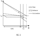
- Waste heat from the thermal processing device via a heat exchanger is used to operate a thermal cycle device (for example, ORC device) and generate electrical or mechanical energy, it could be a requirement on the one hand that a certain area should always have a predetermined minimum temperature. On the other hand, as much waste heat as possible should be used via the heat exchanger. In the following example of a Abgastageübertragers this is further performed.
- the system is designed not to fall below the minimum temperature, it will not be cooled down to the permitted limit during nominal operation, so that the entire exhaust gas potential will not be utilized for the majority of the operating time, which will lead to decreasing system efficiency.
- This is particularly important when the AGWÜ is coupled to a non-stationary process, such as the internal combustion engine of a ship.
- the present invention is not limited to this application, but can be used meaningfully as internal combustion engines in stationary processes and in other heat sources.
- the AGWÜ Due to the fixed, structurally defined area of the AGWÜ, the AGWÜ usually has to be designed for the specific application. For different engines different AGWÜ must be used. This counteracts high standardization and the use of identical parts, which are, however, aimed at.
- the object of the invention is to overcome the disadvantages mentioned at least partially.
- the inventive device for utilizing the waste heat of a thermal processing apparatus comprises a first heat exchanger for transferring heat from a heat flow of the thermal processing apparatus, in particular the internal combustion engine to a heat transfer medium; a second heat exchanger for transferring heat from the heat flow to the heat transfer medium, wherein the second heat transfer is arranged with respect to the heat flow downstream of the first heat exchanger; a thermodynamic cycle apparatus, in particular an organic Rankine cycle apparatus, with a third heat exchanger for transferring heat from the heat transfer medium to a working medium of the thermodynamic cycle apparatus and with a fourth heat exchanger for transferring heat from the heat transfer medium to the working medium, wherein the fourth heat exchanger in With respect to the flow of the working medium upstream of the third heat exchanger is arranged; wherein in the third heat exchanger cooled heat transfer medium is at least partially supplied to the first heat exchanger for heating and wherein in the fourth heat exchanger cooled heat transfer medium is at least partially fed to the second heat exchanger for heating.
- the device according to the invention has the advantage that with the aid of the means for controlling the mass flow of the heat transfer medium flowing through the second or fourth heat exchanger, a variable adaptation to the changing operating conditions of the thermal processing device (for example of the internal combustion engine) can take place.
- the heat present in the heat flow exhaust gas flow
- the first heat exchanger removes heat from the exhaust gas at a comparatively higher temperature level than the second heat exchanger.
- the third heat exchanger transfers heat to the working medium of the thermodynamic cycle apparatus at a comparatively higher temerature level than the fourth heat exchanger.
- the inventive device can be further developed such that the first and the third heat exchanger can be arranged in a first heat transfer medium circuit with a first pump and the second and the fourth heat exchanger can be arranged in a second heat transfer medium circuit with a second pump, wherein by the second Heat exchanger in the second heat transfer medium circuit flowing mass flow of the heat transfer medium can be controlled, in particular by means of a bypass line for at least partially bridging the second heat exchanger and a valve for adjusting the bridging portion of the mass flow.
- a bypass line for at least partially bridging the second heat exchanger and a valve for adjusting the bridging portion of the mass flow.
- the heat transfer medium in the two circuits may be the same or different.
- the heat transfer medium may comprise water in both circuits.
- the first, second, third and fourth heat exchanger can be arranged in a heat transfer medium circuit with a first pump, wherein the flowing through the fourth heat exchanger mass flow of the heat transfer medium can be controlled, in particular by means of a bypass line for at least partially bridging the fourth heat exchanger and a valve for adjusting the bridging portion of the mass flow.
- the heat transfer medium may comprise water in the heat transfer medium circulation.
- a connection between an output of the second heat exchanger can be provided with an input of the first heat exchanger, whereby from the output of the second heat exchanger exiting heat transfer medium can be fully fed to the input of the first heat exchanger. In this way, a coupling of the first and second heat exchanger results.
- first and the second heat exchanger can be arranged in a common housing, the connection of the output of the second heat exchanger with the input of the first heat exchanger can be formed within the housing, and the housing has a first input for supplying Heat transfer medium to the first heat exchanger, a second input for supplying heat transfer medium to the second heat exchanger and an output for discharging heat transfer medium from the first heat exchanger may have.
- the housing has a first input for supplying Heat transfer medium to the first heat exchanger, a second input for supplying heat transfer medium to the second heat exchanger and an output for discharging heat transfer medium from the first heat exchanger may have.
- the first pump between an outlet for heat transfer medium of the third heat exchanger and an input for heat transfer medium of the first heat exchanger can be arranged, and downstream of the first pump may be provided a branch for heat transfer medium to the fourth heat exchanger.
- the circulation of the heat transfer medium can be maintained. Heat transfer medium is also pumped to the fourth heat exchanger via the branch.
- a diaphragm for generating a flow resistance to the input of the first heat exchanger can be provided, or between the junction and an input of the fourth heat exchanger, a further pump can be provided. In this way, an improved promotion of the heat transfer medium to the fourth heat exchanger and then to the second heat exchanger is ensured.
- thermodynamic cycle device further comprises an expansion machine for generating mechanical energy from in the third and fourth heat exchanger to the working medium transferred heat energy, in particular with a coupled with the expansion machine generator for generating electrical Energy, a capacitor for condensing expanded in the expansion machine working fluid and a feed pump for pumping the working fluid may include.
- thermodynamic cycle apparatus may further comprise a cooling circuit with heat transfer medium for the condenser, a condenser for removing heat from the heat transfer medium and a second pump for pumping the heat transfer medium, wherein the thermodynamic cycle device may be bridged to heat to be removed from the heat transfer medium circuit via the radiator.
- thermodynamic cycle device for bridging the thermodynamic cycle device in the heat transfer medium circuit a branch with a second valve for discharging to be cooled heat transfer medium to the radiator and a supply for supplying cooled in the heat transfer medium to the heat transfer medium circuit may be provided, and wherein in the cooling circuit, a third Valve may be provided for blocking the cooling circuit.
- the cooling circuit for the thermodynamic cycle device can be interrupted and there can be a circulation of heat transfer medium from the heat transfer medium circuit via the radiator.
- the third valve can be arranged in the cooling circuit between a feed point and a discharge point for the heat transfer medium from the heat transfer medium circuit, preferably still a check valve between the feed point and the discharge point may be provided to flow when the third valve is open from the feed point to the discharge point, bypassing the radiator.
- a fifth heat exchanger for transferring heat from a cooling liquid of the thermal processing device, in particular of the internal combustion engine, and / or heat of another low-temperature heat source to the working fluid of the thermodynamic cycle device may be, wherein the fifth heat exchanger with respect to the flow of the working medium upstream or downstream of the fourth heat exchanger may be arranged.
- the object according to the invention is furthermore achieved by a method according to claim 13.
- the inventive method for utilizing the waste heat of a thermal processing apparatus comprises the following steps: transfer of heat from a heat flow of the thermal processing apparatus, in particular an exhaust gas stream of the internal combustion engine, to heat transfer medium with a first heat exchanger; Transferring heat from the heat flow to the heat transfer medium with a second heat exchanger, wherein the second heat exchanger is arranged with respect to the heat flow downstream of the first heat exchanger; Transfer of heat from the heat transfer medium to a working medium of a thermodynamic cycle device, in particular an Organic Rankine cycle device, with a third heat exchanger, and transferring heat from the heat transfer medium to the working medium with a fourth heat exchanger of the thermodynamic cycle apparatus, wherein the fourth heat exchanger in relation is disposed on the flow of the working medium upstream of the third heat exchanger; wherein in the third heat exchanger cooled heat transfer medium is at least partially supplied to the first heat exchanger for heating and wherein in the fourth heat exchanger cooled heat transfer medium is at least partially supplied to the second heat exchanger
- the first and the third heat exchanger can be arranged in a first heat transfer medium circuit with a first pump and the second and the fourth heat exchanger can be arranged in a second heat transfer medium circuit with a second pump, wherein the second heat exchanger in the second heat transfer medium circuit flowing mass flow of the heat transfer medium can be controlled, in particular by at least partially bridging the second heat exchanger by means of a bypass line and by adjusting the bridging portion of the mass flow with a valve.
- first, second, third and fourth heat exchangers can be arranged in a heat transfer medium circuit with a first pump, wherein the mass flow of the heat transfer medium flowing through the fourth heat exchanger can be controlled, in particular by at least partially bridging the fourth heat exchanger by means a bypass line and by adjusting the bridging portion of the mass flow with a valve.
- An essential feature of the invention is to ensure optimum use of the heat of a mass flow (for example, waste heat of an exhaust stream) even in operation off the design (rated operation). At the same time the falling below a minimum temperature (for example, exhaust gas temperature) is avoided in order to protect the mass flow from excessive cooling.
- the interconnection according to the invention additionally enables the heat dissipation of an engine or other heat source (e.g., a refrigeration cycle) to be redundant and to assure failure or non-use / partial load of the ORC.
- the interconnections provide further advantages, which are mentioned below and explained in detail in connection with the embodiments.
- the advantages include the fact that the heat potential (eg exhaust heat potential) is fully utilized and the system efficiency increases that exhaust gas condensation and corrosion in the exhaust gas heat exchanger - AGWÜ (first heat exchanger) is avoided, that even if one of the two pumps fails, the heat from the Exhaust and engine cooling water can be dissipated, which is why the pumps do not need to be redundant, that a variable flow through the economizer (Eco, second heat exchanger) allows adaptation to changing operating conditions, such as that a AGWÜ fits different engines, and that also a reduced Heat transfer is compensated by increasing pollution.
- the heat potential eg exhaust heat potential
- AGWÜ first heat exchanger
- Fig. 1 shows a first embodiment of the device according to the invention.
- the first embodiment 100 includes a first heat exchanger 11 (AGWÜ) for transferring heat from an exhaust gas stream of an internal combustion engine to a Heat transfer medium; a second heat exchanger 12 (economizer, Eco) for transferring heat from the exhaust stream to a heat transfer medium, the second heat exchanger 12 being disposed downstream of the first heat exchanger 11 with respect to the exhaust stream; an Organic Rankine Cycle device (ORC) 60, with a third heat exchanger 13 (evaporator) for transferring heat from the heat transfer medium to a working medium of the thermodynamic cycle apparatus and with a fourth heat exchanger 14 (preheater) for transferring heat from the heat transfer medium to the Working medium, wherein the fourth heat exchanger 14 is disposed upstream of the third heat exchanger 13 with respect to the flow of the working medium; wherein in the third heat exchanger 13 cooled heat transfer medium is at least partially supplied to the first heat exchanger 11 for heating and wherein in the fourth heat exchanger 14 cooled heat transfer medium is at least partially fed to the second heat exchanger 12 for heating.
- the first and third heat exchangers 11, 13 are arranged in a first heat transfer medium circuit with a first pump 21 and the second and fourth heat exchangers 12, 14 are arranged in a second heat transfer medium circuit with a second pump 22, wherein the mass flow of the heat transfer medium flowing through the second heat exchanger 12 in the second heat transfer medium circuit by means of a bypass line 31 for at least partially bridging the second heat exchanger 12 and a valve 41 for adjusting the bridging portion of the mass flow is controllable.
- the ORC device 60 further includes an expansion engine 61, a condenser 62, and a feed pump 63.
- the condenser 62 is also part of a refrigeration cycle with a radiator 71 (eg, an air cooler) and a coolant pump 72. Alternatively, the condenser 62 may also heat directly deliver in air (not shown).
- Fig. 2 shows a second embodiment of the device according to the invention.
- the second embodiment 200 further includes a fifth heat exchanger 15 for transferring heat from a cooling liquid of the internal combustion engine 50 to the working fluid of the thermodynamic cycle apparatus, the fifth heat exchanger 15 being disposed upstream of the fourth heat exchanger 14 with respect to the flow of the working medium.
- a fifth heat exchanger 15 for transferring heat from a cooling liquid of the internal combustion engine 50 to the working fluid of the thermodynamic cycle apparatus, the fifth heat exchanger 15 being disposed upstream of the fourth heat exchanger 14 with respect to the flow of the working medium.
- coupled to the engine 50 cooling circuit is shown with the engine radiator 51, from which the cooling liquid via the third heat exchanger 15 and a pump 23 is branched off.
- the other components correspond to those of the first embodiment 100 according to FIG Fig. 1 ,
- the presented interconnections according to the first and second embodiments 100, 200 have the peculiarity of a variably permeable exhaust gas economizer (Eco) 12.
- the majority of the waste heat is the ORC process via the exhaust gas heat exchanger (AGWÜ) 11 in the high-temperature circuit (HT) available ,
- the heat transferred to the heat transfer medium heat is used in the evaporator 13 for evaporation of the working medium.
- the heat transfer medium flows through the Eco 12 and cools the exhaust gas to the desired temperature, wherein the heat to the preheater (VW) 14 is supplied.
- the 3-way valve 41 is opened.
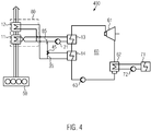
- Fig. 4 shows a third embodiment of the device according to the invention.
- the first, second, third and fourth heat exchangers 11, 12, 13, 14 are arranged in a heat transfer medium circuit with a first pump 21, wherein the through the fourth heat exchanger 14 flowing mass flow of the heat transfer medium by means of a bypass line 35 for at least partially bridging the fourth heat exchanger 14 and a valve 45 for adjusting the bridging portion of the mass flow is controllable.
- the mass flow through the fourth heat exchanger 14 for example by passing at least a portion of the mass flow of the heat transfer medium in the bypass line 35 by means of valve 45, the heat supplied to the working medium by the fourth heat exchanger 14 and / or the heat removed from the exhaust gas can be controlled.
- the two hot water circuits are connected to each other. This results in the advantage that only one hot water circulating pump 21 is needed.
- the position of the 3-way valve 45 can be changed, so that instead of the Eco 12, the preheater (VW) 14 can be bypassed.
- the variation of the position of the 3-way valve 45 is in this case according to both Verschaltungstinen Fig. 1 and 2 such as Fig. 4 possible.
- the exhaustion of the full exhaust gas potential is independent of the engine operating point. If the minimum temperature of the exhaust gas is not yet reached by the cooling through the AGWÜ alone, the valve is opened (in whole or in part), whereby the VW 14 is flowed through.
- the orifice 85 creates a flow resistance in the direct line to the AGWÜ 11 for the water to flow to the 3-way valve 45.
- a further, controllable pump can be provided to direct the mass flow direction VW 14.
- the water from the DC link is further cooled by the VW 14 and then reheated in Eco 12. See the fourth embodiment according to Fig. 5 ,
- the eco-inlet temperature is adjusted such that the flue gas is cooled to the desired temperature.
- the valve 45 is opened, as a result of which the VW 14 is increasingly bypassed. Less heat is coupled into the ORC 60, while the water entering the Eco 12 has a higher temperature, preferably close to the dew point of the exhaust gas located. As a result, a condensation of the exhaust gas is prevented.
- the advantage of this position of the 3-way valve 45 is that the AGWÜ 11 is always flowed through. This can not form local hot spots that would cause evaporation of the water.
- the interconnection has other advantages.
- the temperature and mass flow variable flow through the Ecos can be used to control the cooling of the exhaust gas in the Eco.
- the process can be adapted to the respective exhaust gas parameters (temperatures, mass flows) of the respective heat source. If the amount of heat in the exhaust gas is no longer sufficient for eco-operation, the exhaust gas cooling can be limited by increasing the water inlet temperature while at the same time absorbing less heat from ORC. This achieves a higher standardization since a smaller range of different AGWUs can cover the same or a wider range of heat sources (e.g., diesel and gas engines). It is also possible to set a fixed flow of AGWÜ when a heat source is to be operated in a stationary point.
- the hot water temperature in the economizer which corresponds to the mass flow of water through the economizer, can continue to increase the distance, so the temperature difference between the exhaust gas temperature and the water temperature. This reduces the area required for heat transfer in the AGWÜ. In return, the area for heat transfer from the water to the working medium increases in turn.
- the area for the evaporator and preheater is specifically cheaper than for the AGWÜ, so that there is still an economic advantage here.
- the heat exchanger surfaces for Eco and AGWÜ can be integrated in a single exhaust gas heat exchanger (see dashed line in FIG Fig. 4 ).
- the hot water circuit can be connected within the housing 80 so that only three hot water connections to the AGWÜ are necessary.
- the AGWÜ can be constructed much more compactly and the cost of pipework can be reduced.
- Fig. 5 shows a fourth embodiment of the device according to the invention.
- FIG. 5 A modification of the third embodiment according to Fig. 4 is in Fig. 5 shown as a fourth embodiment 500.
- a further controllable pump 24 is provided to direct the mass flow in the direction of the heat transfer 14 (preheater VW 14) and metering.
- the water from the DC link is further cooled by the VW 14 and then reheated in Eco 12.
- the interconnection can be further improved in order to be able to better guarantee their functionality in the use of internal combustion engines for drive purposes or continuous power generation.
- this may not lead to the maneuverability of a powered by the internal combustion engine vessel, such as overheating of the water circuit or the engine cooling water.
- the circulation pumps of the water intermediate circuit or the ORC cooling circuit must be redundantly designed as double pumps, which means additional costs but also an additional installation and maintenance.
- the interconnection according to the fifth embodiment 600 according to Fig. 6 offers this required runflat capability.
- standard components ie non-redundant pumps
- the hot water circuit and the cooling circuit as shown in the drawing, connected to each other.
- the boiling temperature of a fluid depends on the pressure level, therefore have hot water lines and their components according to the prior art, a higher pressure rating than cold water pipes, which is associated with increased costs and requirements for the material.
- the present interconnection makes it necessary because of the connecting line in a non-obvious way that both water circuits are designed for the same, higher operating pressure.
- the heat can be conducted past the ORC 60 and cooled by the cooling system, for which the valve 75 is opened.
- the pump 21 in the hot water circuit the pump 72 would take over this task in the cooling water circuit.
- the lockable valve 76 and the open 3-way valve 75 ensure that the water is not recirculated, but through the heat exchanger (AGWÜ 11 and Eco 12) is passed and dissipates the heat reliable.
- a check valve 77 is provided as shown here.
Landscapes
- Engineering & Computer Science (AREA)
- Chemical & Material Sciences (AREA)
- Combustion & Propulsion (AREA)
- Mechanical Engineering (AREA)
- General Engineering & Computer Science (AREA)
- Engine Equipment That Uses Special Cycles (AREA)
Abstract
Die Erfindung betrifft eine Vorrichtung zur Nutzung der Abwärme einer Thermoprozessvorrichtung, insbesondere eines Verbrennungsmotors, umfassend: einen ersten Wärmeübertrager zum Übertragen von Wärme aus einem Wärmestrom einer Thermoprozessvorrichtung, insbesondere eines Verbrennungsmotors, auf ein Wärmeträgermedium; einen zweiten Wärmeübertrager zum Übertragen von Wärme aus dem Wärmestrom auf ein Wärmeträgermedium, wobei der zweite Wärmeübertrager in Bezug auf den Wärmestrom stromabwärts vom ersten Wärmeübertrager angeordnet ist; eine thermodynamische Kreisprozessvorrichtung, insbesondere eine Organic Rankine Cycle-Vorrichtung, mit einem dritten Wärmeübertrager zum Übertragen von Wärme aus dem Wärmeträgermedium auf ein Arbeitsmedium der thermodynamischen Kreisprozessvorrichtung und mit einem vierten Wärmeübertrager zum Übertragen von Wärme aus dem Wärmeträgermedium auf das Arbeitsmedium, wobei der vierte Wärmeübertrager in Bezug auf den Strom des Arbeitsmediums stromaufwärts vom zweiten Wärmeübertrager angeordnet ist; wobei im dritten Wärmeübertrager abgekühltes Wärmeträgermedium zumindest teilweise dem ersten Wärmeübertrager zum Erwärmen zuführbar ist und wobei im vierten Wärmeübertrager abgekühltes Wärmeträgermedium zumindest teilweise dem zweiten Wärmeübertrager zum Erwärmen zuführbar ist. Weiterhin umfasst die erfindungsgemäße Vorrichtung Mittel zum Steuern des durch den zweiten oder vierten Wärmeübertrager fließenden Massenstroms des Wärmeträgermediums.. Weiterhin betrifft die Erfindung ein entsprechendes Verfahren zur Nutzung der Abwärme einer Thermoprozessvorrichtung, insbesondere eines Verbrennungsmotors.The invention relates to a device for utilizing the waste heat of a thermal processing device, in particular an internal combustion engine, comprising: a first heat exchanger for transferring heat from a heat flow of a thermal processing device, in particular an internal combustion engine, to a heat transfer medium; a second heat exchanger for transferring heat from the heat flow to a heat transfer medium, wherein the second heat transfer is arranged with respect to the heat flow downstream of the first heat exchanger; a thermodynamic cycle apparatus, in particular an organic Rankine cycle apparatus, with a third heat exchanger for transferring heat from the heat transfer medium to a working medium of the thermodynamic cycle apparatus and with a fourth heat exchanger for transferring heat from the heat transfer medium to the working medium, wherein the fourth heat exchanger in With respect to the flow of the working medium upstream of the second heat exchanger is arranged; wherein in the third heat exchanger cooled heat transfer medium is at least partially supplied to the first heat exchanger for heating and wherein in the fourth heat exchanger cooled heat transfer medium is at least partially fed to the second heat exchanger for heating. Furthermore, the inventive device comprises means for controlling the flowing through the second or fourth heat exchanger mass flow of the heat transfer medium .. Furthermore, the invention relates to a corresponding method for using the waste heat of a thermal processing apparatus, in particular an internal combustion engine.
Description
Die Erfindung betrifft eine Vorrichtung zur Nutzung der Abwärme einer Thermoprozessvorrichtung, insbesondere eines Verbrennungsmotors, wobei die Vorrichtung umfasst: einen ersten Wärmeübertrager zum Übertragen von Wärme aus einem Wärmestrom einer Thermoprozessvorrichtung, insbesondere eines Verbrennungsmotors, auf ein Wärmeträgermedium; einen zweiten Wärmeübertrager zum Übertragen von Wärme aus dem Wärmestrom auf das Wärmeträgermedium, wobei der zweite Wärmeübertrager in Bezug auf den Wärmestrom stromabwärts vom ersten Wärmeübertrager angeordnet ist; eine thermodynamische Kreisprozessvorrichtung, insbesondere eine Organic Rankine Cycle-Vorrichtung (ORC-Vorrichtung), mit einem dritten Wärmeübertrager zum Übertragen von Wärme aus dem Wärmeträgermedium auf ein Arbeitsmedium der thermodynamischen Kreisprozessvorrichtung und mit einem vierten Wärmeübertrager zum Übertragen von Wärme aus dem Wärmeträgermedium auf das Arbeitsmedium, wobei der vierte Wärmeübertrager in Bezug auf den Strom des Arbeitsmediums stromaufwärts vom dritten Wärmeübertrager angeordnet ist; wobei im dritten Wärmeübertrager abgekühltes Wärmeträgermedium zumindest teilweise dem ersten Wärmeübertrager zum Erwärmen zuführbar ist und wobei im vierten Wärmeübertrager abgekühltes Wärmeträgermedium zumindest teilweise dem zweiten Wärmeübertrager zum Erwärmen zuführbar ist. Weiterhin betrifft die Erfindung ein entsprechendes Verfahren.The invention relates to a device for utilizing the waste heat of a thermal processing device, in particular an internal combustion engine, the device comprising: a first heat exchanger for transferring heat from a heat flow of a thermal processing device, in particular an internal combustion engine, to a heat transfer medium; a second heat exchanger for transferring heat from the heat flow to the heat transfer medium, wherein the second heat transfer is arranged with respect to the heat flow downstream of the first heat exchanger; a thermodynamic cycle apparatus, in particular an Organic Rankine Cycle apparatus (ORC apparatus), with a third heat exchanger for transferring heat from the heat transfer medium to a working medium of the thermodynamic cycle apparatus and with a fourth heat exchanger for transferring heat from the heat transfer medium to the working medium, wherein the fourth heat exchanger is located upstream of the third heat exchanger with respect to the flow of the working medium; wherein in the third heat exchanger cooled heat transfer medium is at least partially supplied to the first heat exchanger for heating and wherein in the fourth heat exchanger cooled heat transfer medium is at least partially fed to the second heat exchanger for heating. Furthermore, the invention relates to a corresponding method.
Bei einem thermischen Prozess in einer Thermoprozessvorrichtung können Anforderungen hinsichtlich der Temperatur in einem bestimmten Bereich der Thermoprozessvorrichtung bestehen, um beispielsweise eine gute Funktion zu gewährleisten oder um einen Verschleiß gewisser Elemente der Thermoprozessvorrichtung zu vermeiden. Wird Abwärme von der Thermoprozessvorrichtung über einen Wärmetauscher genutzt, um damit eine thermische Kreisprozessvorrichtung (beispielsweise ORC-Vorrichtung) zu betreiben und elektrische oder mechanische Energie zu erzeugen, könnte es einerseits ein Erfordernis sein, dass ein bestimmter Bereich immer eine vorgegebene Mindesttemperatur aufweisen soll. Andererseits soll über den Wärmetauscher möglichst viel Abwärme genutzt werden. Im nachfolgenden Beispiel eines Abgaswärmeübertragers wird dies weiter ausgeführt.In a thermal process in a thermal processing device, there may be temperature requirements in a particular area of the thermal processing device, for example to ensure good performance or to avoid wear of certain elements of the thermal processing device. Waste heat from the thermal processing device via a heat exchanger is used to operate a thermal cycle device (for example, ORC device) and generate electrical or mechanical energy, it could be a requirement on the one hand that a certain area should always have a predetermined minimum temperature. On the other hand, as much waste heat as possible should be used via the heat exchanger. In the following example of a Abgaswärmeübertragers this is further performed.
Bei der Auslegung der Wärmezufuhr aus dem Abgas eines Verbrennungsmotors (z.B. Dieselmotor) zu einem ORC-System, um daraus beispielsweise elektrische Energie zu gewinnen, aber auch ganz allgemein gibt es im Zusammenhang mit einem Abgaswärmeübertrager (AGWÜ) prinzipiell die folgenden zwei Grenzbereiche. Wird das System auf die maximale Abkühlung im Nennbetrieb ausgelegt, wird bei schwacher Last eine Mindesttemperatur im Abgas unterschritten, was zur Kondensation von Abgasbestandteilen und als Folge davon zur Korrosion und Verschmutzung (z.B. durch Rußbildung) des AGWÜ führt. Dies ist insbesondere bei Brennstoffen mit hohen Schwefelkonzentrationen wie z.B. Biogas oder Schweröl oder auch unvollständiger Verbrennung problematisch. Wird das System dagegen darauf ausgelegt, die Mindesttemperatur nicht zu unterschreiten, wird im Nennbetrieb nicht bis an die erlaubte Grenze abgekühlt, so dass im überwiegenden Teil der Betriebszeit nicht das gesamte Abgaspotenzial ausgenutzt wird, was zu einem sinkenden Systemwirkungsgrad führt. Dies ist insbesondere dann von Bedeutung, wenn der AGWÜ an einen nicht-stationären Prozess gekoppelt ist, wie beispielsweise an den Verbrennungsmotor eines Schiffes. Die vorliegende Erfindung ist jedoch nicht auf diesen Anwendungsfall beschränkt, sondern kann auch bei stationären Prozessen und bei anderen Wärmequellen als Verbrennungsmotoren sinnvoll eingesetzt werden.When interpreting the heat input from the exhaust gas of an internal combustion engine (e.g., diesel engine) to an ORC system to obtain electrical energy therefrom, for example, but also quite generally, there are the following two limits in the context of an exhaust gas heat exchanger (AGWU). If the system is designed for maximum cooling during nominal operation, a low exhaust gas temperature drops below a minimum temperature in the exhaust gas, which leads to condensation of exhaust gas constituents and as a consequence to corrosion and contamination (eg due to soot formation) of the AGWÜ. This is especially true for fuels with high sulfur concentrations, e.g. Biogas or heavy oil or incomplete combustion problematic. If, on the other hand, the system is designed not to fall below the minimum temperature, it will not be cooled down to the permitted limit during nominal operation, so that the entire exhaust gas potential will not be utilized for the majority of the operating time, which will lead to decreasing system efficiency. This is particularly important when the AGWÜ is coupled to a non-stationary process, such as the internal combustion engine of a ship. However, the present invention is not limited to this application, but can be used meaningfully as internal combustion engines in stationary processes and in other heat sources.
Aufgrund der unveränderlichen, konstruktiv festgelegten Fläche des AGWÜ muss der AGWÜ üblicherweise auf den spezifischen Anwendungsfall ausgelegt werden. Für unterschiedliche Motoren müssen unterschiedliche AGWÜ verwendet werden. Das wirkt einer hohen Standardisierung und einer Verwendung von Gleichteilen entgegen, die jedoch angestrebt werden.Due to the fixed, structurally defined area of the AGWÜ, the AGWÜ usually has to be designed for the specific application. For different engines different AGWÜ must be used. This counteracts high standardization and the use of identical parts, which are, however, aimed at.
Gleichzeitig sollte sichergestellt werden, dass die vom AGWÜ eingetragene Wärme auch dann abgeführt werden kann, wenn das ORC-System ausfällt. Denn insbesondere bei der Verwendung von Verbrennungsmotoren für Antriebszwecke oder eine durchgängige Stromerzeugung bestehen harte Anforderungen an die Notlauffähigkeiten der Komponenten. Daher sollte das ORC-System so ausgeführt werden, dass bei Ausfall des ORC-Systems oder seiner Komponenten die Funktion des Antriebes nicht einschränkt wird. Drehende Maschinen wie Pumpen sind Komponenten, die besonders anfällig für Verschleiß und Ausfall sind, und diese werden daher bisher immer redundant bzw. doppelt ausgeführt. Dies führt zu erhöhten Gesamtkosten.At the same time, it should be ensured that the heat registered by the AGWÜ can be dissipated even if the ORC system fails. For in particular when using internal combustion engines for drive purposes or Continuous power generation places heavy demands on the emergency running capabilities of the components. Therefore, the ORC system should be designed so that if the ORC system or its components fail, the function of the drive will not be limited. Rotary machines such as pumps are components that are particularly susceptible to wear and failure, and these are therefore always carried out redundant or double. This leads to increased overall costs.
Aufgabe der Erfindung ist es, die genannten Nachteile zumindest teilweise zu überwinden.The object of the invention is to overcome the disadvantages mentioned at least partially.
Diese Aufgabe wird gelöst durch eine Vorrichtung nach Anspruch 1.This object is achieved by a device according to claim 1.
Die erfindungsgemäße Vorrichtung zur Nutzung der Abwärme einer Thermoprozessvorrichtung, insbesondere eines Verbrennungsmotors umfasst einen ersten Wärmeübertrager zum Übertragen von Wärme aus einem Wärmestrom der Thermoprozessvorrichtung, insbesondere des Verbrennungsmotors auf ein Wärmeträgermedium; einen zweiten Wärmeübertrager zum Übertragen von Wärme aus dem Wärmestrom auf das Wärmeträgermedium, wobei der zweite Wärmeübertrager in Bezug auf den Wärmestrom stromabwärts vom ersten Wärmeübertrager angeordnet ist; eine thermodynamische Kreisprozessvorrichtung, insbesondere eine Organic Rankine Cycle-Vorrichtung, mit einem dritten Wärmeübertrager zum Übertragen von Wärme aus dem Wärmeträgermedium auf ein Arbeitsmedium der thermodynamischen Kreisprozessvorrichtung und mit einem vierten Wärmeübertrager zum Übertragen von Wärme aus dem Wärmeträgermedium auf das Arbeitsmedium, wobei der vierte Wärmeübertrager in Bezug auf den Strom des Arbeitsmediums stromaufwärts vom dritten Wärmeübertrager angeordnet ist; wobei im dritten Wärmeübertrager abgekühltes Wärmeträgermedium zumindest teilweise dem ersten Wärmeübertrager zum Erwärmen zuführbar ist und wobei im vierten Wärmeübertrager abgekühltes Wärmeträgermedium zumindest teilweise dem zweiten Wärmeübertrager zum Erwärmen zuführbar ist. Weiterhin umfasst die erfindungsgemäße Vorrichtung Mittel zum Steuern des durch den zweiten oder vierten Wärmeübertrager fließenden Massenstroms des Wärmeträgermediums.The inventive device for utilizing the waste heat of a thermal processing apparatus, in particular an internal combustion engine comprises a first heat exchanger for transferring heat from a heat flow of the thermal processing apparatus, in particular the internal combustion engine to a heat transfer medium; a second heat exchanger for transferring heat from the heat flow to the heat transfer medium, wherein the second heat transfer is arranged with respect to the heat flow downstream of the first heat exchanger; a thermodynamic cycle apparatus, in particular an organic Rankine cycle apparatus, with a third heat exchanger for transferring heat from the heat transfer medium to a working medium of the thermodynamic cycle apparatus and with a fourth heat exchanger for transferring heat from the heat transfer medium to the working medium, wherein the fourth heat exchanger in With respect to the flow of the working medium upstream of the third heat exchanger is arranged; wherein in the third heat exchanger cooled heat transfer medium is at least partially supplied to the first heat exchanger for heating and wherein in the fourth heat exchanger cooled heat transfer medium is at least partially fed to the second heat exchanger for heating. Furthermore, the Device according to the invention means for controlling the mass flow of the heat transfer medium flowing through the second or fourth heat exchanger.
Die erfindungsgemäße Vorrichtung hat den Vorteil, dass mit Hilfe der Mittel zum Steuern des durch den zweiten oder vierten Wärmeübertrager fließenden Massenstroms des Wärmeträgermediums eine variable Anpassung an die sich verändernden Betriebsbedingungen der Thermoprozessvorrichtung (z.B. des Verbrennungsmotors) erfolgen kann. Insbesondere kann die im Wärmestrom (Abgasstrom) vorhandene Wärme möglichst gut genutzt werden, wobei gleichzeitig beispielsweise eine Unterschreitung einer Mindesttemperatur (z.B. Unterschreitung der Abgastemperatur mit dadurch bedingter Kondensation des Abgases) im ersten oder zweiten Wärmeübertrager vermieden wird. Der erste Wärmeübertrager entnimmt dem Abgas Wärme bei einem vergleichweise höheren Temperaturniveau als der zweite Wärmeübertrager. Entsprechend überträgt der dritte Wärmeübertrager Wärme auf das Arbeitsmedium der thermodynamischen Kreisprozessvorrichtung bei einem vergleichsweise höheren Tempertaurniveau als der vierte Wärmeübertrager.The device according to the invention has the advantage that with the aid of the means for controlling the mass flow of the heat transfer medium flowing through the second or fourth heat exchanger, a variable adaptation to the changing operating conditions of the thermal processing device (for example of the internal combustion engine) can take place. In particular, the heat present in the heat flow (exhaust gas flow) can be used as well as possible, while at the same time avoiding a minimum temperature (for example undershooting of the exhaust gas temperature with consequent condensation of the exhaust gas) in the first or second heat exchanger. The first heat exchanger removes heat from the exhaust gas at a comparatively higher temperature level than the second heat exchanger. Accordingly, the third heat exchanger transfers heat to the working medium of the thermodynamic cycle apparatus at a comparatively higher temerature level than the fourth heat exchanger.
Die erfindungsgemäße Vorrichtung kann dahingehend weitergebildet werden, dass der erste und der dritte Wärmeübertrager in einem ersten Wärmeträgermediumkreislauf mit einer ersten Pumpe angeordnet sein können und der zweite und der vierte Wärmeübertrager in einem zweiten Wärmeträgermediumkreislauf mit einer zweiten Pumpe angeordnet sein können, wobei der durch den zweiten Wärmeübertrager im zweiten Wärmeträgermediumkreislauf fließende Massenstrom des Wärmeträgermediums steuerbar sein kann, insbesondere mittels einer Bypassleitung zum wenigstens teilweisen Überbrücken des zweiten Wärmeübertragers und einem Ventil zum Einstellen des überbrückenden Anteils des Massenstroms. Auf diese Weise stehen zwei separate Kreisläufe mit einem Wärmeträgermedium bereit, und zwar ein Hochtemperaturkreislauf mit dem ersten und dritten Wärmeübertrager und ein Niedertemperaturkreislauf mit dem zweiten und vierten Wärmeübertrager. Dabei kann das Wärmeträgermedium in den beiden Kreisläufen gleich oder verschieden sein. Insbesondere kann das Wärmeträgermedium in beiden Kreisläufen Wasser umfassen. Durch Steuern des Massenstroms durch den zweiten Wärmeübertrager, beispielsweise durch Vorbeileiten wenigstens eines Teils des Wärmeüberträgerfluids in der Bypassleitung, kann die dem Abgas durch den zweiten Wärmeübertrager entnommene Wärme und/oder die dem Arbeitsmedium durch den vierten Wärmeübertrager zugeführte Wärme gesteuert werden.The inventive device can be further developed such that the first and the third heat exchanger can be arranged in a first heat transfer medium circuit with a first pump and the second and the fourth heat exchanger can be arranged in a second heat transfer medium circuit with a second pump, wherein by the second Heat exchanger in the second heat transfer medium circuit flowing mass flow of the heat transfer medium can be controlled, in particular by means of a bypass line for at least partially bridging the second heat exchanger and a valve for adjusting the bridging portion of the mass flow. In this way, two separate circuits are provided with a heat transfer medium, namely a high-temperature circuit with the first and third heat exchanger and a low-temperature circuit with the second and fourth heat exchanger. In this case, the heat transfer medium in the two circuits may be the same or different. In particular, the heat transfer medium may comprise water in both circuits. By controlling the mass flow through the second heat exchanger, for example by passing at least a portion of the heat transfer fluid in the bypass line, which the exhaust gas removed by the second heat exchanger Heat and / or the heat supplied to the working medium by the fourth heat exchanger to be controlled.
Eine andere Weiterbildung der erfindungsgemäßen Vorrichtung besteht darin, dass der erste, zweite, dritte und vierte Wärmeübertrager in einem Wärmeträgermediumkreislauf mit einer ersten Pumpe angeordnet sein können, wobei der durch den vierten Wärmeübertrager fließende Massenstrom des Wärmeträgermediums steuerbar sein kann, insbesondere mittels einer Bypassleitung zum wenigstens teilweisen Überbrücken des vierten Wärmeübertragers und einem Ventil zum Einstellen des überbrückenden Anteils des Massenstroms. Dabei kann das Wärmeträgermedium im Wärmeträgermediumkreislauf Wasser umfassen. Durch Steuern den Massenstroms durch den vierten Wärmeübertrager, beispielsweise durch Vorbeileiten wenigstens eines Teils des Massenstroms des Wärmeträgermediums in der Bypassleitung, kann die dem Arbeitsmedium durch den vierten Wärmeübertrager zugeführte Wärme und/oder die dem Abgas entnommene Wärme gesteuert werden.Another development of the device according to the invention is that the first, second, third and fourth heat exchanger can be arranged in a heat transfer medium circuit with a first pump, wherein the flowing through the fourth heat exchanger mass flow of the heat transfer medium can be controlled, in particular by means of a bypass line for at least partially bridging the fourth heat exchanger and a valve for adjusting the bridging portion of the mass flow. In this case, the heat transfer medium may comprise water in the heat transfer medium circulation. By controlling the mass flow through the fourth heat exchanger, for example by passing at least part of the mass flow of the heat transfer medium in the bypass line, the heat supplied to the working medium by the fourth heat exchanger and / or the heat removed from the exhaust gas can be controlled.
Gemäß einer anderen Weiterbildung kann eine Verbindung zwischen einem Ausgang des zweiten Wärmeübertragers mit einem Eingang des ersten Wärmeübertragers vorgesehen sein, wodurch aus dem Ausgang des zweiten Wärmeübertragers austretendes Wärmeträgermedium vollständig dem Eingang des ersten Wärmeübertragers zuführbar sein kann. Auf diese Weise ergibt sich eine Kopplung des ersten und zweiten Wärmeübertragers.According to another embodiment, a connection between an output of the second heat exchanger can be provided with an input of the first heat exchanger, whereby from the output of the second heat exchanger exiting heat transfer medium can be fully fed to the input of the first heat exchanger. In this way, a coupling of the first and second heat exchanger results.
Dies kann dahingehend weitergebildet werden, dass der erste und der zweite Wärmeübertrager in einem gemeinsamen Gehäuse angeordnet sein können, die Verbindung des Ausgangs des zweiten Wärmeübertragers mit dem Eingang des ersten Wärmeübertragers innerhalb des Gehäuses ausgebildet sein kann, und das Gehäuse einen ersten Eingang zum Zuführen von Wärmeträgermedium zum ersten Wärmeübertrager, einen zweiten Eingang zum Zuführen von Wärmeträgermedium zum zweiten Wärmeübertrager und einen Ausgang zum Abführen von Wärmeträgermedium vom ersten Wärmeübertrager aufweisen kann. Auf diese Weise ergibt sich eine kompakte Ausgestaltung des ersten und zweiten Wärmeübertragers als Einzelkomponente. Der Verrohrungsaufwand wird reduziert, da es nur drei Anschlüsse für das Wärmeträgermedium (vorzugsweise Wasser oder Wasser umfassend) gibt.This can be further developed in that the first and the second heat exchanger can be arranged in a common housing, the connection of the output of the second heat exchanger with the input of the first heat exchanger can be formed within the housing, and the housing has a first input for supplying Heat transfer medium to the first heat exchanger, a second input for supplying heat transfer medium to the second heat exchanger and an output for discharging heat transfer medium from the first heat exchanger may have. In this way, results in a compact design of the first and second heat exchanger as a single component. The piping effort is reduced because there are only three connections for the heat transfer medium (preferably comprising water or water).
Gemäß einer anderen Weiterbildung kann die erste Pumpe zwischen einem Ausgang für Wärmeträgermedium des dritten Wärmeübertragers und einem Eingang für Wärmeträgermedium des ersten Wärmeübertragers angeordnet sein, und stromabwärts der ersten Pumpe kann eine Abzweigung für Wärmeträgermedium zum vierten Wärmeübertrager vorgesehen sein. Mit der (einzelnen) Pumpe kann der Kreislauf des Wärmeträgermediums aufrechterhalten werden. Über die Abzweigung wird Wärmeträgermedium auch zum vierten Wärmeübertrager gepumpt.According to another embodiment, the first pump between an outlet for heat transfer medium of the third heat exchanger and an input for heat transfer medium of the first heat exchanger can be arranged, and downstream of the first pump may be provided a branch for heat transfer medium to the fourth heat exchanger. With the (single) pump, the circulation of the heat transfer medium can be maintained. Heat transfer medium is also pumped to the fourth heat exchanger via the branch.
Dies kann dahingehend weitergebildet werden, dass stromabwärts der Abzweigung eine Blende zur Erzeugung eines Strömungswiderstands zum Eingang des ersten Wärmeübertragers vorgesehen sein kann, oder wobei zwischen der Abzweigung und einem Eingang des vierten Wärmeübertragers eine weitere Pumpe vorgesehen sein kann. Auf diese Weise wird eine verbesserte Förderung des Wärmeträgermediums zum vierten Wärmeübertrager und anschließend zum zweiten Wärmeübertrager sicher gestellt.This can be further developed in that downstream of the branch, a diaphragm for generating a flow resistance to the input of the first heat exchanger can be provided, or between the junction and an input of the fourth heat exchanger, a further pump can be provided. In this way, an improved promotion of the heat transfer medium to the fourth heat exchanger and then to the second heat exchanger is ensured.
Eine andere Weiterbildung der erfindungsgemäßen Vorrichtung oder einer der genannten Weiterbildungen besteht darin, dass die thermodynamische Kreisprozessvorrichtung weiterhin eine Expansionsmaschine zur Erzeugung von mechanischer Energie aus im dritten und vierten Wärmeübertrager an das Arbeitsmedium übertragener Wärmeenergie, insbesondere mit einem mit der Expansionsmaschine gekoppelten Generator zur Erzeugung von elektrischer Energie, einen Kondensator zum Kondensieren von in der Expansionsmaschine expandierten Arbeitsmediums und eine Speisepumpe zum Pumpen des Arbeitsmediums umfassen kann.Another development of the device according to the invention or one of the said developments is that the thermodynamic cycle device further comprises an expansion machine for generating mechanical energy from in the third and fourth heat exchanger to the working medium transferred heat energy, in particular with a coupled with the expansion machine generator for generating electrical Energy, a capacitor for condensing expanded in the expansion machine working fluid and a feed pump for pumping the working fluid may include.
Dies kann dahingehend weitergebildet werden, dass die thermodynamische Kreisprozessvorrichtung weiterhin einen Kühlkreislauf mit Wärmeträgermedium für den Kondensator, einem Kühler zum Abführen von Wärme aus dem Wärmeträgermedium und einer zweite Pumpe zum Pumpen des Wärmeträgermediums umfassen kann, wobei die thermodynamische Kreisprozessvorrichtung überbrückbar vorgesehen sein kann, um Wärme aus dem Wärmeträgermediumkreislauf über den Kühler abzuführen. Dies hat den Vorteil, dass bei einer Störung der thermodynamischen Kreisprozessvorrichtung (beispielsweise Ausfall einer deren Komponenten) weiterhin eine Wärmeabfuhr aus dem Abgas des Verbrennungsmotors über den Kühler erfolgen kann.This may be further developed in that the thermodynamic cycle apparatus may further comprise a cooling circuit with heat transfer medium for the condenser, a condenser for removing heat from the heat transfer medium and a second pump for pumping the heat transfer medium, wherein the thermodynamic cycle device may be bridged to heat to be removed from the heat transfer medium circuit via the radiator. This has the advantage that in case of a disturbance of the thermodynamic Circuit processing device (for example, failure of a component) continue to heat removal from the exhaust gas of the engine via the radiator can be done.
Dies kann dahingehend weitergebildet werden, dass zum Überbrücken der thermodynamischen Kreisprozessvorrichtung im Wärmeträgermediumkreislauf eine Abzweigung mit einem zweiten Ventil zum Abführen von zu kühlendem Wärmeträgermedium zum Kühler und eine Zuführung zum Zuführen von im Kühler gekühltem Wärmeträgermedium zum Wärmeträgermediumkreislauf vorgesehen sein können, und wobei im Kühlkreislauf ein drittes Ventil zum Sperren des Kühlkreislaufs vorgesehen sein kann. Mit dem dritten Ventil kann der Kühlkreislauf für die thermodynamische Kreisprozessvorrichtung unterbrochen werden und es kann eine Zirkulation von Wärmeträgermedium aus dem Wärmeträgermediumkreislauf über den Kühler erfolgen.This can be further developed to the effect that for bridging the thermodynamic cycle device in the heat transfer medium circuit a branch with a second valve for discharging to be cooled heat transfer medium to the radiator and a supply for supplying cooled in the heat transfer medium to the heat transfer medium circuit may be provided, and wherein in the cooling circuit, a third Valve may be provided for blocking the cooling circuit. With the third valve, the cooling circuit for the thermodynamic cycle device can be interrupted and there can be a circulation of heat transfer medium from the heat transfer medium circuit via the radiator.
Dies kann dahingehend weitergebildet werden, dass das dritte Ventil im Kühlkreislauf zwischen einem Zuführpunkt und einem Abführpunkt für das Wärmeträgermedium aus dem Wärmeträgermediumkreislauf angeordnet sein kann, wobei vorzugsweise weiterhin eine Rückschlagklappe zwischen dem Zuführpunkt und dem Abführpunkt vorgesehen sein kann, um bei geöffnetem dritten Ventil eine Strömen vom Zuführpunkt zum Abführpunkt unter Umgehung des Kühlers zu verhindern.This can be further developed such that the third valve can be arranged in the cooling circuit between a feed point and a discharge point for the heat transfer medium from the heat transfer medium circuit, preferably still a check valve between the feed point and the discharge point may be provided to flow when the third valve is open from the feed point to the discharge point, bypassing the radiator.
Eine andere Weiterbildung der erfindungsgemäßen Vorrichtung oder einer der genannten Weiterbildungen besteht darin, dass weiterhin ein fünfter Wärmeübertrager zum Übertragen von Wärme aus einer Kühlflüssigkeit der Thermoprozessvorrichtung, insbesondere des Verbrennungsmotors, und/oder von Wärme einer anderen Niedertemperatur-Wärmequelle auf das Arbeitsmedium der thermodynamischen Kreisprozessvorrichtung vorgesehen sein kann, wobei der fünfte Wärmeübertrager in Bezug auf den Strom des Arbeitsmediums stromaufwärts oder stromabwärts vom vierten Wärmeübertrager angeordnet sein kann.Another development of the device according to the invention or one of the said developments is that further provided a fifth heat exchanger for transferring heat from a cooling liquid of the thermal processing device, in particular of the internal combustion engine, and / or heat of another low-temperature heat source to the working fluid of the thermodynamic cycle device may be, wherein the fifth heat exchanger with respect to the flow of the working medium upstream or downstream of the fourth heat exchanger may be arranged.
Die erfindungsgemäße Aufgabe wird weiterhin gelöst durch ein Verfahren nach Anspruch 13.The object according to the invention is furthermore achieved by a method according to
Das erfindungsgemäße Verfahren zur Nutzung der Abwärme einer Thermoprozessvorrichtung, insbesondere eines Verbrennungsmotors, umfasst die folgenden Schritte: Übertragen von Wärme aus einem Wärmestrom der Thermoprozessvorrichtung, insbesondere einem Abgasstrom des Verbrennungsmotors, auf Wärmeträgermedium mit einem ersten Wärmeübertrager; Übertragen von Wärme aus dem Wärmestrom auf Wärmeträgermedium mit einem zweiten Wärmeübertrager, wobei der zweite Wärmeübertrager in Bezug auf den Wärmestrom stromabwärts vom ersten Wärmeübertrager angeordnet ist; Übertragen von Wärme aus dem Wärmeträgermedium auf ein Arbeitsmedium einer thermodynamischen Kreisprozessvorrichtung, insbesondere einer Organic Rankine Cycle-Vorrichtung, mit einem dritten Wärmeübertrager, und Übertragen von Wärme aus dem Wärmeträgermedium auf das Arbeitsmedium mit einem vierten Wärmeübertrager der thermodynamischen Kreisprozessvorrichtung, wobei der vierte Wärmeübertrager in Bezug auf den Strom des Arbeitsmediums stromaufwärts vom dritten Wärmeübertrager angeordnet ist; wobei im dritten Wärmeübertrager abgekühltes Wärmeträgermedium zumindest teilweise dem ersten Wärmeübertrager zum Erwärmen zugeführt wird und wobei im vierten Wärmeübertrager abgekühltes Wärmeträgermedium zumindest teilweise dem zweiten Wärmeübertrager zum Erwärmen zugeführt wird; und wobei das Verfahren weiterhin umfasst: Steuern des durch den zweiten oder vierten Wärmeübertrager fließenden Massenstroms des Wärmeträgermediums.The inventive method for utilizing the waste heat of a thermal processing apparatus, in particular an internal combustion engine, comprises the following steps: transfer of heat from a heat flow of the thermal processing apparatus, in particular an exhaust gas stream of the internal combustion engine, to heat transfer medium with a first heat exchanger; Transferring heat from the heat flow to the heat transfer medium with a second heat exchanger, wherein the second heat exchanger is arranged with respect to the heat flow downstream of the first heat exchanger; Transfer of heat from the heat transfer medium to a working medium of a thermodynamic cycle device, in particular an Organic Rankine cycle device, with a third heat exchanger, and transferring heat from the heat transfer medium to the working medium with a fourth heat exchanger of the thermodynamic cycle apparatus, wherein the fourth heat exchanger in relation is disposed on the flow of the working medium upstream of the third heat exchanger; wherein in the third heat exchanger cooled heat transfer medium is at least partially supplied to the first heat exchanger for heating and wherein in the fourth heat exchanger cooled heat transfer medium is at least partially supplied to the second heat exchanger for heating; and wherein the method further comprises: controlling the mass flow of the heat transfer medium flowing through the second or fourth heat exchanger.
Die Vorteile des erfindungsgemäßen Verfahrens und dessen Weiterbildungen entsprechen - wenn nicht anders angegeben - jenen der erfindungsgemäßen Vorrichtung.The advantages of the method and its developments correspond - unless otherwise stated - those of the device according to the invention.
Gemäß einer Weiterbildung des erfindungsgemäßen Verfahrens können der erste und der dritte Wärmeübertrager in einem ersten Wärmeträgermediumkreislauf mit einer ersten Pumpe angeordnet sein und der zweite und der vierte Wärmeübertrager in einem zweiten Wärmeträgermediumkreislauf mit einer zweiten Pumpe angeordnet sein, wobei der durch den zweiten Wärmeübertrager im zweiten Wärmeträgermediumkreislauf fließende Massenstrom des Wärmeträgermediums gesteuert werden kann, insbesondere durch wenigstens teilweises Überbrücken des zweiten Wärmeübertragers mittels einer Bypassleitung und durch Einstellen des überbrückenden Anteils des Massenstroms mit einem Ventil.According to a development of the method according to the invention, the first and the third heat exchanger can be arranged in a first heat transfer medium circuit with a first pump and the second and the fourth heat exchanger can be arranged in a second heat transfer medium circuit with a second pump, wherein the second heat exchanger in the second heat transfer medium circuit flowing mass flow of the heat transfer medium can be controlled, in particular by at least partially bridging the second heat exchanger by means of a bypass line and by adjusting the bridging portion of the mass flow with a valve.
Eine andere Weiterbildung besteht darin, dass der erste, zweite, dritte und vierte Wärmeübertrager in einem Wärmeträgermediumkreislauf mit einer ersten Pumpe angeordnet sein können, wobei der durch den vierten Wärmeübertrager fließende Massenstrom des Wärmeträgermediums gesteuert werden kann, insbesondere durch wenigstens teilweises Überbrücken des vierten Wärmeübertragers mittels einer Bypassleitung und durch Einstellen des überbrückenden Anteils des Massenstroms mit einem Ventil.Another development consists in that the first, second, third and fourth heat exchangers can be arranged in a heat transfer medium circuit with a first pump, wherein the mass flow of the heat transfer medium flowing through the fourth heat exchanger can be controlled, in particular by at least partially bridging the fourth heat exchanger by means a bypass line and by adjusting the bridging portion of the mass flow with a valve.
Die genannten Weiterbildungen können einzeln eingesetzt oder wie beansprucht geeignet miteinander kombiniert werden.The cited developments can be used individually or combined as claimed suitable.
Weitere Merkmale und beispielhafte Ausführungsformen sowie Vorteile der vorliegenden Erfindung werden nachfolgend anhand der Zeichnungen näher erläutert. Es versteht sich, dass die Ausführungsformen nicht den Bereich der vorliegenden Erfindung erschöpfen. Es versteht sich weiterhin, dass einige oder sämtliche der im Weiteren beschriebenen Merkmale auch auf andere Weise miteinander kombiniert werden können.Further features and exemplary embodiments and advantages of the present invention will be explained in more detail with reference to the drawings. It is understood that the embodiments do not exhaust the scope of the present invention. It is further understood that some or all of the features described below may be combined with each other in other ways.
- Fig. 1Fig. 1
- zeigt eine erste Ausführungsform der erfindungsgemäßen Vorrichtung.shows a first embodiment of the device according to the invention.
- Fig. 2Fig. 2
- zeigt eine zweite Ausführungsform der erfindungsgemäßen Vorrichtung.shows a second embodiment of the device according to the invention.
- Fig. 3Fig. 3
- zeigt ein T-Q-Diagrammshows a T-Q diagram
- Fig. 4Fig. 4
- zeigt eine dritte Ausführungsform der erfindungsgemäßen Vorrichtung.shows a third embodiment of the device according to the invention.
- Fig. 5Fig. 5
- zeigt eine vierte Ausführungsform der erfindungsgemäßen Vorrichtung.shows a fourth embodiment of the device according to the invention.
- Fig. 6Fig. 6
- zeigt eine fünfte Ausführungsform der erfindungsgemäßen Vorrichtung.shows a fifth embodiment of the device according to the invention.
Ein wesentliches Merkmal der Erfindung besteht darin, eine optimale Nutzung der Wärme eines Massenstroms (beispielsweise Abwärme eines Abgasstroms) auch im Betrieb abseits der Auslegung (Nennbetrieb) sicherzustellen. Gleichzeitig wird das Unterschreiten einer minimalen Temperatur (beispielsweise Abgastemperatur) vermieden, um den Massenstrom vor einer zu starken Auskühlung zu schützen. Die erfindungsgemäße Verschaltung gemäß einigen Ausführungsformen ermöglicht zusätzlich die Wärmeabfuhr eines Motors oder einer sonstigen Wärmequelle (z.B. ein Kühlkreislauf) redundant zu gestalten und auch bei Ausfall oder Nichtbenutzung / Teillast des ORC sicherzustellen.An essential feature of the invention is to ensure optimum use of the heat of a mass flow (for example, waste heat of an exhaust stream) even in operation off the design (rated operation). At the same time the falling below a minimum temperature (for example, exhaust gas temperature) is avoided in order to protect the mass flow from excessive cooling. The interconnection according to the invention, according to some embodiments, additionally enables the heat dissipation of an engine or other heat source (e.g., a refrigeration cycle) to be redundant and to assure failure or non-use / partial load of the ORC.
Darüber hinaus ergeben sich durch die Verschaltungen noch weitere Vorteile, die nachfolgend genannt und im Zusammenhang mit den Ausführungsformen im Detail erläutert werden. Als Vorteile sind zu nennen, dass das Wärmepotential (z.B. Abgaswärmepotenzial) voll ausgeschöpft wird und der Systemwirkungsgrad steigt, dass eine Abgaskondensation und Korrosion im Abgaswärmeübertrager - AGWÜ (erster Wärmeübertrager) vermieden wird, dass auch bei einem Ausfall einer der beiden Pumpen die Wärme aus dem Abgas und Motorkühlwasser abgeführt werden kann, weshalb die Pumpen nicht redundant ausgeführt werden müssen, dass eine variable Durchströmung des Economisers (Eco, zweiter Wärmeübertrager) eine Anpassung an veränderliche Betriebsbedingungen ermöglicht, etwa dadurch dass ein AGWÜ auf unterschiedliche Motoren passt, und dass zudem eine verringerter Wärmeübergang durch zunehmende Verschmutzung kompensierbar ist.In addition, the interconnections provide further advantages, which are mentioned below and explained in detail in connection with the embodiments. The advantages include the fact that the heat potential (eg exhaust heat potential) is fully utilized and the system efficiency increases that exhaust gas condensation and corrosion in the exhaust gas heat exchanger - AGWÜ (first heat exchanger) is avoided, that even if one of the two pumps fails, the heat from the Exhaust and engine cooling water can be dissipated, which is why the pumps do not need to be redundant, that a variable flow through the economizer (Eco, second heat exchanger) allows adaptation to changing operating conditions, such as that a AGWÜ fits different engines, and that also a reduced Heat transfer is compensated by increasing pollution.
Die erste Ausführungsform 100 umfasst einen ersten Wärmeübertrager 11 (AGWÜ) zum Übertragen von Wärme aus einem Abgasstrom eines Verbrennungsmotors auf ein Wärmeträgermedium; einen zweiten Wärmeübertrager 12 (Economiser, Eco) zum Übertragen von Wärme aus dem Abgasstrom auf ein Wärmeträgermedium, wobei der zweite Wärmeübertrager 12 in Bezug auf den Abgasstrom stromabwärts vom ersten Wärmeübertrager 11 angeordnet ist; eine Organic Rankine Cycle-Vorrichtung (ORC) 60, mit einem dritten Wärmeübertrager 13 (Verdampfer) zum Übertragen von Wärme aus dem Wärmeträgermedium auf ein Arbeitsmedium der thermodynamischen Kreisprozessvorrichtung und mit einem vierten Wärmeübertrager 14 (Vorwärmer) zum Übertragen von Wärme aus dem Wärmeträgermedium auf das Arbeitsmedium, wobei der vierte Wärmeübertrager 14 in Bezug auf den Strom des Arbeitsmediums stromaufwärts vom dritten Wärmeübertrager 13 angeordnet ist; wobei im dritten Wärmeübertrager 13 abgekühltes Wärmeträgermedium zumindest teilweise dem ersten Wärmeübertrager 11 zum Erwärmen zuführbar ist und wobei im vierten Wärmeübertrager 14 abgekühltes Wärmeträgermedium zumindest teilweise dem zweiten Wärmeübertrager 12 zum Erwärmen zuführbar ist. Weiterhin umfasst die erfindungsgemäße Vorrichtung Mittel 31, 41 zum Steuern des durch den zweiten Wärmeübertrager 12 oder durch den vierten Wärmeübertrager 14 fließenden Massenstroms des Wärmeträgermediums.The
In der erfindungsgemäßen Vorrichtung gemäß der ersten Ausführungsform 100 sind der erste und der dritte Wärmeübertrager 11, 13 in einem ersten Wärmeträgermediumkreislauf mit einer ersten Pumpe 21 angeordnet und der zweite und der vierte Wärmeübertrager 12, 14 in einem zweiten Wärmeträgermediumkreislauf mit einer zweiten Pumpe 22 angeordnet, wobei der durch den zweiten Wärmeübertrager 12 im zweiten Wärmeträgermediumkreislauf fließende Massenstrom des Wärmeträgermediums mittels einer Bypassleitung 31 zum wenigstens teilweisen Überbrücken des zweiten Wärmeübertragers 12 und einem Ventil 41 zum Einstellen des überbrückenden Anteils des Massenstroms steuerbar ist.In the device according to the invention according to the
Die ORC-Vorrichtung 60 umfasst weiterhin eine Expansionsmaschine 61, einen Kondensator 62 und einen Speisepumpe 63. Der Kondensator 62 ist zudem Teil eines Kühlkreislaufs mit einem Kühler 71 (z.B. ein Luftkühler) und einer Kühlmittelpumpe 72. Alternativ kann der Kondensator 62 die Wärme auch direkt an Luft abgeben (nicht dargestellt).The
Die zweite Ausführungsform 200 umfasst weiterhin einen fünfter Wärmeübertrager 15 zum Übertragen von Wärme aus einer Kühlflüssigkeit des Verbrennungsmotors 50 auf das Arbeitsmedium der thermodynamischen Kreisprozessvorrichtung, wobei der fünfte Wärmeübertrager 15 in Bezug auf den Strom des Arbeitsmediums stromaufwärts vom vierten Wärmeübertrager 14 angeordnet ist. Weiterhin ist in dieser Zeichnung der mit dem Verbrennungsmotor 50 gekoppelte Kühlkreislauf mit dem Motorkühler 51 dargestellt, aus welchem die Kühlflüssigkeit über den dritten Wärmeübertrager 15 und eine Pumpe 23 abgezweigt wird. Die weiteren Komponenten entsprechen denen der ersten Ausführungsform 100 gemäß
Die vorgestellten Verschaltungen gemäß der ersten und zweiten Ausführungsform 100, 200 besitzen die Besonderheit eines variabel durchströmbaren Abgaseconomisers (Eco) 12. Der Hauptanteil der Abwärme wird dem ORC-Prozess über den Abgaswärmeübertrager (AGWÜ) 11 im Hochtemperatur-Kreis (HT) zur Verfügung gestellt. Die an das Wärmeträgermedium übertragene Wärme wird im Verdampfer 13 zum Verdampfen des Arbeitsmediums genutzt. Im Niedertemperatur-Kreis (NT) durchströmt das Wärmeträgermedium den Eco 12 und kühlt das Abgas auf die Solltemperatur, wobei die Wärme dem Vorwärmer (VW) 14 zugeführt wird. Wenn sich die Eco-Austrittstemperatur des Abgases der Mindesttemperatur nähert, wird das 3-Wege-Ventil 41 geöffnet. Das Fluid umgeht den Eco 12, dem Abgas wird folglich keine weitere Wärme entzogen. Da die weitere Auskühlung des Abgases gestoppt wird, ist diese Verschaltung sehr zuverlässig, was das Vermeiden der Kondensation von Abgasbestandteilen angeht. Um sicherzugehen, dass im Eco 12 befindliches Wasser nicht zu sieden beginnt, kann ein Mindestdurchfluss gewährleistet werden.The presented interconnections according to the first and
Zur Verdeutlichung dieses Zusammenhangs wird Bezug auf das T-Q-Diagramm gemäß
- Wenn die Gefahr besteht, dass die Abgas-Austrittstemperatur die Mindesttemperatur unterschreitet, wird der Wassermassenstrom durch
den Eco 12 gesenkt. Dadurch erhöht sich die Wasser-Austrittstemperatur bzw. der Gradient der Temperaturerhöhung. Da die Temperaturdifferenz zwischen dem Abgas und dem Heißwasser durch die endliche Wärmeübertragerfläche begrenzt ist, wird die Abgas-Austrittstemperatur durch die Heißwassertemperatur begrenzt. Um dies zu erreichen wird das 3-Wege-Ventil 41 geöffnet.
- If there is a risk that the exhaust gas outlet temperature falls below the minimum temperature, the water mass flow is lowered by the
Eco 12. This increases the water outlet temperature or the gradient of Temperature increase. Since the temperature difference between the exhaust gas and the hot water is limited by the finite heat transfer surface, the exhaust gas outlet temperature is limited by the hot water temperature. To achieve this, the 3-way valve 41 is opened.
Im Lauf der Zeit verringert sich die im AGWÜ 11 übertragene Wärmeleistung Q, da die zunehmenden Ruß- bzw. Schmutzablagerungen auf der Abgasseite den Wärmedurchgang U vom Abgas auf das Wasser verschlechtern. Der Wärmestrom errechnet sich zu: ![]()
![]()
Mit der Wärmeleistung Q, dem Wärmedurchgangskoeffizienten U, der Oberfläche A und der logarithmischen Temperaturdifferenz ΔT log.With the heat output Q, the heat transfer coefficient U, the surface A and the logarithmic temperature difference Δ T log .
Durch die Verschaltung kann dieser Effekt kompensiert werden. Im neuen, nicht verschmutzen Zustand wird die Maximaldurchströmung des Wassers durch den AGWÜ begrenzt. Gemäß dem Zusammenhang ![]()
![]()
In der dritten Ausführungsform 400 der erfindungsgemäßen Vorrichtung sind der erste, zweite, dritte und vierte Wärmeübertrager 11, 12, 13, 14 in einem Wärmeträgermediumkreislauf mit einer ersten Pumpe 21 angeordnet, wobei der durch den vierten Wärmeübertrager 14 fließende Massenstrom des Wärmeträgermediums mittels einer Bypassleitung 35 zum wenigstens teilweisen Überbrücken des vierten Wärmeübertragers 14 und einem Ventil 45 zum Einstellen des überbrückenden Anteils des Massenstroms steuerbar ist. Durch Steuern des Massenstroms durch den vierten Wärmeübertrager 14, beispielsweise durch Vorbeileiten wenigstens eines Teils des Massenstroms des Wärmeträgermediums in der Bypassleitung 35 mittels Ventil 45, kann die dem Arbeitsmedium durch den vierten Wärmeübertrager 14 zugeführte Wärme und/oder die dem Abgas entnommene Wärme gesteuert werden.In the
Dabei sind die beiden Heißwasserkreise miteinander verbunden. Hieraus ergibt sich der Vorteil, dass nur eine Heißwasser-Umwälzpumpe 21 benötigt wird. Ebenso kann die Position des 3-Wege-Ventiles 45 geändert werden, so dass statt dem Eco 12 der Vorwärmer (VW) 14 umgangen werden kann. Die Variation der Position des 3-Wege-Ventils 45 ist hierbei für beide Verschaltungsvarianten gemäß
Auch in dieser Variante ist die Ausschöpfung des vollen Abgaspotenzials unabhängig vom Motor-Betriebspunkt gegeben. Wenn die Minimaltemperatur des Abgases durch die Auskühlung über den AGWÜ allein noch nicht erreicht wird, wird das Ventil (ganz oder teilweise) geöffnet, wodurch der VW 14 durchströmt wird. Die Blende 85 erzeugt einen Strömungswiderstand in der direkten Leitung zum AGWÜ 11, damit das Wasser zum 3-Wege-Ventil 45 strömt.Also in this variant, the exhaustion of the full exhaust gas potential is independent of the engine operating point. If the minimum temperature of the exhaust gas is not yet reached by the cooling through the AGWÜ alone, the valve is opened (in whole or in part), whereby the
Alternativ kann anstelle des 3-Wege-Ventils eine weitere, regelbare Pumpe vorgesehen werden um den Massenstrom Richtung VW 14 zu leiten. Das Wasser aus dem Zwischenkreis wird durch den VW 14 weiter ausgekühlt und anschließend im Eco 12 wieder erwärmt. Siehe dazu die vierte Ausführungsform gemäß
Erfindungsgemäß wird die Eco-Eintrittstemperatur derart eingestellt, dass das Rauchgas auf die Solltemperatur ausgekühlt wird. Sobald die Abgas-Austrittstemperatur aus dem Eco 12 unter die Solltemperatur sinkt, wird das Ventil 45 geöffnet, wodurch der VW 14 zunehmend umgangen wird. Es wird weniger Wärme in den ORC 60 eingekoppelt, während das Wasser welches dem Eco 12 zuströmt, eine höhere Temperatur aufweist, die sich vorzugsweise nahe dem Taupunkt des Abgases befindet. Hierdurch wird eine Kondensation des Abgases verhindert. Der Vorteil dieser Position des 3-Wege-Ventils 45 liegt darin, dass der AGWÜ 11 immer durchströmt wird. Dadurch können sich keine lokalen Hot-Spots bilden die eine Verdampfung des Wassers zur Folge hätten.According to the invention, the eco-inlet temperature is adjusted such that the flue gas is cooled to the desired temperature. As soon as the exhaust gas outlet temperature from the
Die Verschaltung besitzt weitere Vorteile. Über die Temperatur- und Massenstromvariable Durchströmung des Ecos lässt sich die Abkühlung des Abgases im Eco steuern. Dadurch kann der Prozess an die jeweiligen Abgasparameter (Temperaturen, Massenströme) der jeweiligen Wärmequelle angepasst werden. Wenn die Wärmemenge im Abgas nicht mehr für den Eco-Betrieb ausreicht, kann die Abgaskühlung begrenzt werden, indem die Wasser-Eintrittstemperatur erhöht wird, wobei gleichzeitig weniger Wärme von ORC-aufgenommen wird. Hierdurch wird eine höhere Standardisierung erreicht, da mit einer geringeren Palette an unterschiedlichen AGWÜ dieselbe oder eine größere Bandbreite an Wärmequellen (z.B. Diesel- und Gasmotoren) abgedeckt werden kann. Ebenso ist es möglich, eine feste Durchströmung des AGWÜ einzustellen, wenn eine Wärmequelle in einem stationären Punkt betrieben werden soll. Auch hier ermöglicht eine feste Aufteilung (die jedoch von Fall zu Fall variiert werden kann) eine Abdeckung verschiedener Leistungsgrößen. Im Extremfall passt ein standardisierter AGWÜ auf alle relevanten Anwendungen (stationär, nicht-stationär, sowie verschieden geartete Wärmequellen). Dadurch wird erreicht, dass mehr Gleichteile eingesetzt werden können, was große logistische und wirtschaftliche Vorteile mit sich bringt.The interconnection has other advantages. The temperature and mass flow variable flow through the Ecos can be used to control the cooling of the exhaust gas in the Eco. As a result, the process can be adapted to the respective exhaust gas parameters (temperatures, mass flows) of the respective heat source. If the amount of heat in the exhaust gas is no longer sufficient for eco-operation, the exhaust gas cooling can be limited by increasing the water inlet temperature while at the same time absorbing less heat from ORC. This achieves a higher standardization since a smaller range of different AGWUs can cover the same or a wider range of heat sources (e.g., diesel and gas engines). It is also possible to set a fixed flow of AGWÜ when a heat source is to be operated in a stationary point. Again, a fixed distribution (which may, however, be varied from case to case) allows coverage of different performance sizes. In extreme cases, a standardized AGWÜ fits all relevant applications (stationary, non-stationary, as well as various types of heat sources). This ensures that more equal parts can be used, which brings great logistical and economic benefits.
Über die Spreizung der Heißwassertemperatur im Economiser, die mit dem Wassermassenstrom durch den Economiser korrespondiert, lässt sich weiterhin der Abstand, also die Temperaturdifferenz, zwischen der Abgastemperatur und der Wassertemperatur vergrößern. Hierdurch verringert sich die für die Wärmeübertragung benötigte Fläche im AGWÜ. Zwar vergrößert sich im Gegenzug dazu die Fläche für die Wärmeübertragung vom Wasser auf das Arbeitsmedium. Die Fläche für den Verdampfer und Vorwärmer ist jedoch spezifisch günstiger als für den AGWÜ, so dass sich hier noch ein wirtschaftlicher Vorteil ergibt.By spreading the hot water temperature in the economizer, which corresponds to the mass flow of water through the economizer, can continue to increase the distance, so the temperature difference between the exhaust gas temperature and the water temperature. This reduces the area required for heat transfer in the AGWÜ. In return, the area for heat transfer from the water to the working medium increases in turn. However, the area for the evaporator and preheater is specifically cheaper than for the AGWÜ, so that there is still an economic advantage here.
In einer weiteren Verbesserung können die Wärmetauscherflächen für Eco und AGWÜ in einem einzigen Abgaswärmetauscher integriert sein (Siehe gestrichelte Markierung in
Eine Abwandlung der dritten Ausführungsform gemäß
Anstelle des 3-Wege-Ventils (und der Blende) ist eine weitere, regelbare Pumpe 24 vorgesehen, um den Massenstrom in Richtung des Wärmeübertrages 14 (Vorwärmer VW 14) zu leiten und zu dosieren. Das Wasser aus dem Zwischenkreis wird durch den VW 14 weiter ausgekühlt und anschließend im Eco 12 wieder erwärmt.Instead of the 3-way valve (and the diaphragm) is a further
Die Verschaltung kann weiterhin verbessert werden um deren Funktionsfähigkeit bei der Verwendung von Verbrennungsmotoren für Antriebszwecke oder eine durchgängige Stromerzeugung besser gewährleisten zu können. Für den Fall, dass einzelne Komponenten des ORC-Systems ausfallen, darf dies beispielsweise nicht zur Manövrierunfähigkeit eines mit dem Verbrennungsmotor angetriebenen Schiffes führen, etwa durch Überhitzung des Wasserkreises oder des Motorkühlwassers. Hier müssen gemäß des Stands der Technik beispielsweise die Umwälzpumpen des Wasserzwischenkreises oder des ORC-Kühlkreises redundant als Doppelpumpen ausgeführt werden, was Mehrkosten bedeutet aber auch einen zusätzlichen Installations- und Wartungsaufwand.The interconnection can be further improved in order to be able to better guarantee their functionality in the use of internal combustion engines for drive purposes or continuous power generation. For example, in the event that individual components of the ORC system fail, this may not lead to the maneuverability of a powered by the internal combustion engine vessel, such as overheating of the water circuit or the engine cooling water. Here, according to the prior art, for example, the circulation pumps of the water intermediate circuit or the ORC cooling circuit must be redundantly designed as double pumps, which means additional costs but also an additional installation and maintenance.
Die Verschaltung gemäß der fünften Ausführungsform 600 nach
Auf diese Weise kann bei Ausfall des ORC Systems die Wärme am ORC 60 vorbei geleitet werden und durch das Kühlsystem gekühlt werden, dazu wird das Ventil 75 geöffnet. Bei Ausfall beispielsweise der Pumpe 21 im Heißwasserkreis würde die Pumpe 72 im Kühlwasserkreis diese Aufgabe übernehmen. Das absperrbare Ventil 76 und das geöffnete 3-Wege-Ventil 75 stellen sicher, dass das Wasser nicht rezirkuliert, sondern durch die Wärmeübertrager (AGWÜ 11 und Eco 12) geleitet wird und die Wärme betriebssicher abführt. Zudem ist hier eine Rückschlagklappe 77 wie eingezeichnet vorgesehen.In this way, in the event of failure of the ORC system, the heat can be conducted past the
Ebenso verhält es sich bei Ausfall der Pumpe 72. Durch die Verschaltung ist nun der Betrieb des ORC 60 komplett vom Motorbetrieb entkoppelt.The same applies if the
Die dargestellten Ausführungsformen sind lediglich beispielhaft und der vollständige Umfang der vorliegenden Erfindung wird durch die Ansprüche definiert.The illustrated embodiments are merely exemplary and the full scope of the present invention is defined by the claims.
Claims (15)
Priority Applications (8)
| Application Number | Priority Date | Filing Date | Title |
|---|---|---|---|
| DK18158794.0T DK3530890T3 (en) | 2018-02-27 | 2018-02-27 | Drive with integrated ORC |
| EP18158794.0A EP3530890B1 (en) | 2018-02-27 | 2018-02-27 | Drive with integrated orc |
| KR1020207026900A KR102615752B1 (en) | 2018-02-27 | 2019-01-07 | Drive unit with integrated ORC |
| PCT/EP2019/050211 WO2019166137A1 (en) | 2018-02-27 | 2019-01-07 | Drive having an integrated orc |
| US16/976,445 US11352911B2 (en) | 2018-02-27 | 2019-01-07 | Drive having an integrated ORC |
| BR112020016793-2A BR112020016793B1 (en) | 2018-02-27 | 2019-01-07 | DEVICE FOR UTILIZING THE WASTE HEAT FROM A THERMAL PROCESS DEVICE AND METHOD FOR UTILIZING THE WASTE HEAT FROM A THERMAL PROCESS DEVICE |
| JP2020568023A JP7229276B2 (en) | 2018-02-27 | 2019-01-07 | Drive with integrated ORC |
| CN201980015612.9A CN111902613A (en) | 2018-02-27 | 2019-01-07 | Drive device with integrated ORC |
Applications Claiming Priority (1)
| Application Number | Priority Date | Filing Date | Title |
|---|---|---|---|
| EP18158794.0A EP3530890B1 (en) | 2018-02-27 | 2018-02-27 | Drive with integrated orc |
Publications (2)
| Publication Number | Publication Date |
|---|---|
| EP3530890A1 true EP3530890A1 (en) | 2019-08-28 |
| EP3530890B1 EP3530890B1 (en) | 2022-10-12 |
Family
ID=61386772
Family Applications (1)
| Application Number | Title | Priority Date | Filing Date |
|---|---|---|---|
| EP18158794.0A Active EP3530890B1 (en) | 2018-02-27 | 2018-02-27 | Drive with integrated orc |
Country Status (7)
| Country | Link |
|---|---|
| US (1) | US11352911B2 (en) |
| EP (1) | EP3530890B1 (en) |
| JP (1) | JP7229276B2 (en) |
| KR (1) | KR102615752B1 (en) |
| CN (1) | CN111902613A (en) |
| DK (1) | DK3530890T3 (en) |
| WO (1) | WO2019166137A1 (en) |
Families Citing this family (2)
| Publication number | Priority date | Publication date | Assignee | Title |
|---|---|---|---|---|
| CN111794820B (en) * | 2020-06-09 | 2021-09-03 | 同济大学 | Organic Rankine cycle system |
| CN112196634B (en) * | 2020-10-16 | 2022-12-30 | 南昌智能新能源汽车研究院 | Power generation system based on cooling circulation loop of automobile internal combustion engine and CFD simulation optimization method thereof |
Citations (3)
| Publication number | Priority date | Publication date | Assignee | Title |
|---|---|---|---|---|
| US20150377180A1 (en) * | 2013-02-20 | 2015-12-31 | Renault S.A.S. | System for recuperating heat from the exhaust gases in an internal combustion engine, with two heat exchangers on a gas recirculation circuit |
| US20160061059A1 (en) * | 2010-12-23 | 2016-03-03 | Cummins Intellectual Property, Inc. | System and method for regulating egr cooling using a rankine cycle |
| DE102016100912A1 (en) * | 2015-01-23 | 2016-07-28 | Ford Global Technologies, Llc | Thermodynamic system in a vehicle |
Family Cites Families (17)
| Publication number | Priority date | Publication date | Assignee | Title |
|---|---|---|---|---|
| JPS6133902U (en) * | 1984-08-02 | 1986-03-01 | 三菱重工業株式会社 | Thermal storage power generation device |
| JPS61152916A (en) * | 1984-12-27 | 1986-07-11 | Toshiba Corp | Binary cycle power generation plant |
| US6571548B1 (en) * | 1998-12-31 | 2003-06-03 | Ormat Industries Ltd. | Waste heat recovery in an organic energy converter using an intermediate liquid cycle |
| JP4908383B2 (en) * | 2006-11-24 | 2012-04-04 | ベール ゲーエムベーハー ウント コー カーゲー | System with organic Rankine cycle circulation for driving at least one expansion device, heat exchanger for driving the expansion device and method for operating at least one expansion device |
| JP2008255923A (en) * | 2007-04-06 | 2008-10-23 | Sanden Corp | Exhaust heat utilizing device for internal combustion engine |
| DE102007041944B3 (en) * | 2007-09-04 | 2009-02-19 | Gesellschaft für Motoren und Kraftanlagen mbH | Apparatus for energy conversion, combined heat and power plant with such an apparatus and method for operating an ORC plant |
| GB2457266B (en) * | 2008-02-07 | 2012-12-26 | Univ City | Generating power from medium temperature heat sources |
| WO2010024246A1 (en) * | 2008-08-26 | 2010-03-04 | サンデン株式会社 | Waste heat utilization device for internal combustion engine |
| DE102009014185B4 (en) * | 2009-03-20 | 2010-12-16 | GMK-Gesellschaft für Motoren und Kraftanlagen mbH | Device for energy conversion according to the ORC principle, ORC system with such a device and method for starting up and / or operating such a device |
| DE102010011737B4 (en) * | 2010-03-17 | 2012-06-06 | Henry Schwarz | Method and device for energy conversion |
| DE102011009280A1 (en) * | 2011-01-25 | 2012-07-26 | Frank Eckert | System i.e. combustion engine, for converting thermal energy into e.g. mechanical energy, has heat transfer medium circuit for transferring thermal energy of heat sources, where partial flow of medium is permitted |
| JP6070224B2 (en) * | 2013-01-31 | 2017-02-01 | アイシン精機株式会社 | Power generator |
| EP3159506B1 (en) * | 2015-10-21 | 2020-08-19 | Orcan Energy AG | Functional synergies in the integration of orc systems in combustion engines |
| DE102016217731A1 (en) * | 2016-09-16 | 2018-03-22 | Robert Bosch Gmbh | Waste heat recovery system |
| JP6781673B2 (en) * | 2017-06-22 | 2020-11-04 | 株式会社神戸製鋼所 | Thermal energy recovery device |
| WO2019086960A1 (en) * | 2017-11-03 | 2019-05-09 | Victor Juchymenko | System, apparatus and method for managing heat transfer in power generation systems |
| CN108561241A (en) * | 2018-01-10 | 2018-09-21 | 西安交通大学 | A kind of electricity generation system utilized based on afterheat of IC engine |
-
2018
- 2018-02-27 DK DK18158794.0T patent/DK3530890T3/en active
- 2018-02-27 EP EP18158794.0A patent/EP3530890B1/en active Active
-
2019
- 2019-01-07 WO PCT/EP2019/050211 patent/WO2019166137A1/en active Application Filing
- 2019-01-07 KR KR1020207026900A patent/KR102615752B1/en active IP Right Grant
- 2019-01-07 CN CN201980015612.9A patent/CN111902613A/en active Pending
- 2019-01-07 US US16/976,445 patent/US11352911B2/en active Active
- 2019-01-07 JP JP2020568023A patent/JP7229276B2/en active Active
Patent Citations (3)
| Publication number | Priority date | Publication date | Assignee | Title |
|---|---|---|---|---|
| US20160061059A1 (en) * | 2010-12-23 | 2016-03-03 | Cummins Intellectual Property, Inc. | System and method for regulating egr cooling using a rankine cycle |
| US20150377180A1 (en) * | 2013-02-20 | 2015-12-31 | Renault S.A.S. | System for recuperating heat from the exhaust gases in an internal combustion engine, with two heat exchangers on a gas recirculation circuit |
| DE102016100912A1 (en) * | 2015-01-23 | 2016-07-28 | Ford Global Technologies, Llc | Thermodynamic system in a vehicle |
Also Published As
| Publication number | Publication date |
|---|---|
| WO2019166137A1 (en) | 2019-09-06 |
| US20210003039A1 (en) | 2021-01-07 |
| EP3530890B1 (en) | 2022-10-12 |
| JP2021515138A (en) | 2021-06-17 |
| KR102615752B1 (en) | 2023-12-19 |
| DK3530890T3 (en) | 2023-01-16 |
| US11352911B2 (en) | 2022-06-07 |
| BR112020016793A2 (en) | 2020-12-15 |
| CN111902613A (en) | 2020-11-06 |
| KR20200122361A (en) | 2020-10-27 |
| JP7229276B2 (en) | 2023-02-27 |
Similar Documents
| Publication | Publication Date | Title |
|---|---|---|
| EP3159506B1 (en) | Functional synergies in the integration of orc systems in combustion engines | |
| EP1925806B1 (en) | System with an organic Rankine cycle for operating at least one expansion machine, heat exchanger for operating one expansion machine, method for operating at least one expansion machine | |
| DE60315823T2 (en) | METHOD AND DEVICE FOR GENERATING ELECTRICITY FROM THE HEAT AT THE CORE OF AT LEAST ONE HIGH-TEMPERATURE CORE REACTOR | |
| DE102014019684A1 (en) | Arrangement for converting thermal energy from heat loss of an internal combustion engine | |
| EP2992194A1 (en) | Cooling circuit | |
| WO2015197456A1 (en) | Cooling and energy recovery system | |
| EP3006682B1 (en) | Device and method for operating a heating distribution station | |
| EP3530890B1 (en) | Drive with integrated orc | |
| EP3447256B1 (en) | System for cooling a process fluid from a heat producing installation | |
| WO2008031716A2 (en) | Steam circuit process with improved energy utilisation | |
| DE10155508C5 (en) | Method and device for generating electrical energy | |
| WO2015067434A1 (en) | Method for operating a system for recovering energy from a waste heat stream of an internal-combustion engine | |
| DE102016222687B4 (en) | heat supply device | |
| DE102008020637B4 (en) | Hot water supply system with a hot water tank | |
| EP2108813A1 (en) | Device for cooling or heating a combustion engine | |
| DE102018205130A1 (en) | Method for heating a drive of a hybrid vehicle and preheating device | |
| WO2005088113A1 (en) | Internal combustion engine having a humidifying device and a heat exchanger | |
| DE102016220634A1 (en) | Waste heat power plant with gradual heat supply | |
| WO2016162118A1 (en) | Device for waste heat recovery, and method for operating same | |
| DE102020002880A1 (en) | Thermal management system, method for cooling a condenser of a waste heat recovery system and associated equipment | |
| DE102016112013B4 (en) | Working Fluid Collector for Rankine Process Waste Heat Reuse System | |
| DE102017200887A1 (en) | Arrangement with a system for carrying out a thermodynamic cycle and an internal combustion engine, and method for operating such an arrangement | |
| DE102020119369B4 (en) | Warm air ventilation system with heat recovery | |
| DE102018213086B4 (en) | Split cooling system for internal combustion engine | |
| DE102017209827A1 (en) | Internal combustion engine and motor vehicle |
Legal Events
| Date | Code | Title | Description |
|---|---|---|---|
| PUAI | Public reference made under article 153(3) epc to a published international application that has entered the european phase |
Free format text: ORIGINAL CODE: 0009012 |
|
| STAA | Information on the status of an ep patent application or granted ep patent |
Free format text: STATUS: THE APPLICATION HAS BEEN PUBLISHED |
|
| AK | Designated contracting states |
Kind code of ref document: A1 Designated state(s): AL AT BE BG CH CY CZ DE DK EE ES FI FR GB GR HR HU IE IS IT LI LT LU LV MC MK MT NL NO PL PT RO RS SE SI SK SM TR |
|
| AX | Request for extension of the european patent |
Extension state: BA ME |
|
| STAA | Information on the status of an ep patent application or granted ep patent |
Free format text: STATUS: REQUEST FOR EXAMINATION WAS MADE |
|
| 17P | Request for examination filed |
Effective date: 20200212 |
|
| RBV | Designated contracting states (corrected) |
Designated state(s): AL AT BE BG CH CY CZ DE DK EE ES FI FR GB GR HR HU IE IS IT LI LT LU LV MC MK MT NL NO PL PT RO RS SE SI SK SM TR |
|
| GRAP | Despatch of communication of intention to grant a patent |
Free format text: ORIGINAL CODE: EPIDOSNIGR1 |
|
| STAA | Information on the status of an ep patent application or granted ep patent |
Free format text: STATUS: GRANT OF PATENT IS INTENDED |
|
| INTG | Intention to grant announced |
Effective date: 20220422 |
|
| RIN1 | Information on inventor provided before grant (corrected) |
Inventor name: AUMANN, RICHARD Inventor name: WALTER, DANIELA Inventor name: SPRINGER, JENS-PATRICK Inventor name: LANGER, ROY Inventor name: SCHUSTER, ANDREAS |
|
| GRAS | Grant fee paid |
Free format text: ORIGINAL CODE: EPIDOSNIGR3 |
|
| GRAA | (expected) grant |
Free format text: ORIGINAL CODE: 0009210 |
|
| STAA | Information on the status of an ep patent application or granted ep patent |
Free format text: STATUS: THE PATENT HAS BEEN GRANTED |
|
| AK | Designated contracting states |
Kind code of ref document: B1 Designated state(s): AL AT BE BG CH CY CZ DE DK EE ES FI FR GB GR HR HU IE IS IT LI LT LU LV MC MK MT NL NO PL PT RO RS SE SI SK SM TR |
|
| REG | Reference to a national code |
Ref country code: GB Ref legal event code: FG4D Free format text: NOT ENGLISH |
|
| REG | Reference to a national code |
Ref country code: CH Ref legal event code: EP |
|
| REG | Reference to a national code |
Ref country code: DE Ref legal event code: R096 Ref document number: 502018010804 Country of ref document: DE |
|
| REG | Reference to a national code |
Ref country code: IE Ref legal event code: FG4D Free format text: LANGUAGE OF EP DOCUMENT: GERMAN |
|
| REG | Reference to a national code |
Ref country code: AT Ref legal event code: REF Ref document number: 1524302 Country of ref document: AT Kind code of ref document: T Effective date: 20221115 |
|
| REG | Reference to a national code |
Ref country code: NL Ref legal event code: FP |
|
| REG | Reference to a national code |
Ref country code: DK Ref legal event code: T3 Effective date: 20230111 |
|
| REG | Reference to a national code |
Ref country code: SE Ref legal event code: TRGR |
|
| REG | Reference to a national code |
Ref country code: LT Ref legal event code: MG9D |
|
| PG25 | Lapsed in a contracting state [announced via postgrant information from national office to epo] |
Ref country code: PT Free format text: LAPSE BECAUSE OF FAILURE TO SUBMIT A TRANSLATION OF THE DESCRIPTION OR TO PAY THE FEE WITHIN THE PRESCRIBED TIME-LIMIT Effective date: 20230213 Ref country code: NO Free format text: LAPSE BECAUSE OF FAILURE TO SUBMIT A TRANSLATION OF THE DESCRIPTION OR TO PAY THE FEE WITHIN THE PRESCRIBED TIME-LIMIT Effective date: 20230112 Ref country code: LT Free format text: LAPSE BECAUSE OF FAILURE TO SUBMIT A TRANSLATION OF THE DESCRIPTION OR TO PAY THE FEE WITHIN THE PRESCRIBED TIME-LIMIT Effective date: 20221012 Ref country code: FI Free format text: LAPSE BECAUSE OF FAILURE TO SUBMIT A TRANSLATION OF THE DESCRIPTION OR TO PAY THE FEE WITHIN THE PRESCRIBED TIME-LIMIT Effective date: 20221012 Ref country code: ES Free format text: LAPSE BECAUSE OF FAILURE TO SUBMIT A TRANSLATION OF THE DESCRIPTION OR TO PAY THE FEE WITHIN THE PRESCRIBED TIME-LIMIT Effective date: 20221012 |
|
| PG25 | Lapsed in a contracting state [announced via postgrant information from national office to epo] |
Ref country code: RS Free format text: LAPSE BECAUSE OF FAILURE TO SUBMIT A TRANSLATION OF THE DESCRIPTION OR TO PAY THE FEE WITHIN THE PRESCRIBED TIME-LIMIT Effective date: 20221012 Ref country code: PL Free format text: LAPSE BECAUSE OF FAILURE TO SUBMIT A TRANSLATION OF THE DESCRIPTION OR TO PAY THE FEE WITHIN THE PRESCRIBED TIME-LIMIT Effective date: 20221012 Ref country code: LV Free format text: LAPSE BECAUSE OF FAILURE TO SUBMIT A TRANSLATION OF THE DESCRIPTION OR TO PAY THE FEE WITHIN THE PRESCRIBED TIME-LIMIT Effective date: 20221012 Ref country code: IS Free format text: LAPSE BECAUSE OF FAILURE TO SUBMIT A TRANSLATION OF THE DESCRIPTION OR TO PAY THE FEE WITHIN THE PRESCRIBED TIME-LIMIT Effective date: 20230212 Ref country code: HR Free format text: LAPSE BECAUSE OF FAILURE TO SUBMIT A TRANSLATION OF THE DESCRIPTION OR TO PAY THE FEE WITHIN THE PRESCRIBED TIME-LIMIT Effective date: 20221012 Ref country code: GR Free format text: LAPSE BECAUSE OF FAILURE TO SUBMIT A TRANSLATION OF THE DESCRIPTION OR TO PAY THE FEE WITHIN THE PRESCRIBED TIME-LIMIT Effective date: 20230113 |
|
| REG | Reference to a national code |
Ref country code: DE Ref legal event code: R097 Ref document number: 502018010804 Country of ref document: DE |
|
| PG25 | Lapsed in a contracting state [announced via postgrant information from national office to epo] |
Ref country code: SM Free format text: LAPSE BECAUSE OF FAILURE TO SUBMIT A TRANSLATION OF THE DESCRIPTION OR TO PAY THE FEE WITHIN THE PRESCRIBED TIME-LIMIT Effective date: 20221012 Ref country code: RO Free format text: LAPSE BECAUSE OF FAILURE TO SUBMIT A TRANSLATION OF THE DESCRIPTION OR TO PAY THE FEE WITHIN THE PRESCRIBED TIME-LIMIT Effective date: 20221012 Ref country code: EE Free format text: LAPSE BECAUSE OF FAILURE TO SUBMIT A TRANSLATION OF THE DESCRIPTION OR TO PAY THE FEE WITHIN THE PRESCRIBED TIME-LIMIT Effective date: 20221012 Ref country code: CZ Free format text: LAPSE BECAUSE OF FAILURE TO SUBMIT A TRANSLATION OF THE DESCRIPTION OR TO PAY THE FEE WITHIN THE PRESCRIBED TIME-LIMIT Effective date: 20221012 |
|
| PLBE | No opposition filed within time limit |
Free format text: ORIGINAL CODE: 0009261 |
|
| STAA | Information on the status of an ep patent application or granted ep patent |
Free format text: STATUS: NO OPPOSITION FILED WITHIN TIME LIMIT |
|
| PG25 | Lapsed in a contracting state [announced via postgrant information from national office to epo] |
Ref country code: SK Free format text: LAPSE BECAUSE OF FAILURE TO SUBMIT A TRANSLATION OF THE DESCRIPTION OR TO PAY THE FEE WITHIN THE PRESCRIBED TIME-LIMIT Effective date: 20221012 Ref country code: AL Free format text: LAPSE BECAUSE OF FAILURE TO SUBMIT A TRANSLATION OF THE DESCRIPTION OR TO PAY THE FEE WITHIN THE PRESCRIBED TIME-LIMIT Effective date: 20221012 |
|
| 26N | No opposition filed |
Effective date: 20230713 |
|
| PG25 | Lapsed in a contracting state [announced via postgrant information from national office to epo] |
Ref country code: MC Free format text: LAPSE BECAUSE OF FAILURE TO SUBMIT A TRANSLATION OF THE DESCRIPTION OR TO PAY THE FEE WITHIN THE PRESCRIBED TIME-LIMIT Effective date: 20221012 |
|
| REG | Reference to a national code |
Ref country code: CH Ref legal event code: PL |
|
| REG | Reference to a national code |
Ref country code: BE Ref legal event code: MM Effective date: 20230228 |
|
| PG25 | Lapsed in a contracting state [announced via postgrant information from national office to epo] |
Ref country code: LU Free format text: LAPSE BECAUSE OF NON-PAYMENT OF DUE FEES Effective date: 20230227 Ref country code: LI Free format text: LAPSE BECAUSE OF NON-PAYMENT OF DUE FEES Effective date: 20230228 Ref country code: CH Free format text: LAPSE BECAUSE OF NON-PAYMENT OF DUE FEES Effective date: 20230228 |
|
| PG25 | Lapsed in a contracting state [announced via postgrant information from national office to epo] |
Ref country code: SI Free format text: LAPSE BECAUSE OF FAILURE TO SUBMIT A TRANSLATION OF THE DESCRIPTION OR TO PAY THE FEE WITHIN THE PRESCRIBED TIME-LIMIT Effective date: 20221012 |
|
| REG | Reference to a national code |
Ref country code: IE Ref legal event code: MM4A |
|
| PG25 | Lapsed in a contracting state [announced via postgrant information from national office to epo] |
Ref country code: IE Free format text: LAPSE BECAUSE OF NON-PAYMENT OF DUE FEES Effective date: 20230227 |
|
| PG25 | Lapsed in a contracting state [announced via postgrant information from national office to epo] |
Ref country code: BE Free format text: LAPSE BECAUSE OF NON-PAYMENT OF DUE FEES Effective date: 20230228 |
|
| REG | Reference to a national code |
Ref country code: AT Ref legal event code: MM01 Ref document number: 1524302 Country of ref document: AT Kind code of ref document: T Effective date: 20230227 |
|
| PGFP | Annual fee paid to national office [announced via postgrant information from national office to epo] |
Ref country code: NL Payment date: 20240222 Year of fee payment: 7 |
|
| PG25 | Lapsed in a contracting state [announced via postgrant information from national office to epo] |
Ref country code: AT Free format text: LAPSE BECAUSE OF NON-PAYMENT OF DUE FEES Effective date: 20230227 |
|
| PG25 | Lapsed in a contracting state [announced via postgrant information from national office to epo] |
Ref country code: AT Free format text: LAPSE BECAUSE OF NON-PAYMENT OF DUE FEES Effective date: 20230227 |
|
| PGFP | Annual fee paid to national office [announced via postgrant information from national office to epo] |
Ref country code: DE Payment date: 20240226 Year of fee payment: 7 Ref country code: GB Payment date: 20240221 Year of fee payment: 7 |
|
| PGFP | Annual fee paid to national office [announced via postgrant information from national office to epo] |
Ref country code: SE Payment date: 20240222 Year of fee payment: 7 Ref country code: IT Payment date: 20240227 Year of fee payment: 7 Ref country code: FR Payment date: 20240227 Year of fee payment: 7 Ref country code: DK Payment date: 20240222 Year of fee payment: 7 |