EP3530499A1 - Suspension device for vehicles - Google Patents
Suspension device for vehicles Download PDFInfo
- Publication number
- EP3530499A1 EP3530499A1 EP17872081.9A EP17872081A EP3530499A1 EP 3530499 A1 EP3530499 A1 EP 3530499A1 EP 17872081 A EP17872081 A EP 17872081A EP 3530499 A1 EP3530499 A1 EP 3530499A1
- Authority
- EP
- European Patent Office
- Prior art keywords
- vehicle
- coil spring
- damper
- knuckle
- vehicle body
- Prior art date
- Legal status (The legal status is an assumption and is not a legal conclusion. Google has not performed a legal analysis and makes no representation as to the accuracy of the status listed.)
- Granted
Links
- 239000000725 suspension Substances 0.000 title claims abstract description 48
- 230000007935 neutral effect Effects 0.000 claims abstract description 6
- 238000005452 bending Methods 0.000 description 23
- 230000000052 comparative effect Effects 0.000 description 12
- 229920001971 elastomer Polymers 0.000 description 10
- 239000005060 rubber Substances 0.000 description 10
- 238000004804 winding Methods 0.000 description 4
- 239000000428 dust Substances 0.000 description 2
- 230000009286 beneficial effect Effects 0.000 description 1
- 238000000034 method Methods 0.000 description 1
- 238000012986 modification Methods 0.000 description 1
- 230000004048 modification Effects 0.000 description 1
- 230000002093 peripheral effect Effects 0.000 description 1
- 238000006467 substitution reaction Methods 0.000 description 1
- 238000003466 welding Methods 0.000 description 1
Images


Classifications
-
- B—PERFORMING OPERATIONS; TRANSPORTING
- B60—VEHICLES IN GENERAL
- B60G—VEHICLE SUSPENSION ARRANGEMENTS
- B60G11/00—Resilient suspensions characterised by arrangement, location or kind of springs
- B60G11/14—Resilient suspensions characterised by arrangement, location or kind of springs having helical, spiral or coil springs only
- B60G11/16—Resilient suspensions characterised by arrangement, location or kind of springs having helical, spiral or coil springs only characterised by means specially adapted for attaching the spring to axle or sprung part of the vehicle
-
- B—PERFORMING OPERATIONS; TRANSPORTING
- B60—VEHICLES IN GENERAL
- B60G—VEHICLE SUSPENSION ARRANGEMENTS
- B60G3/00—Resilient suspensions for a single wheel
- B60G3/02—Resilient suspensions for a single wheel with a single pivoted arm
- B60G3/04—Resilient suspensions for a single wheel with a single pivoted arm the arm being essentially transverse to the longitudinal axis of the vehicle
- B60G3/06—Resilient suspensions for a single wheel with a single pivoted arm the arm being essentially transverse to the longitudinal axis of the vehicle the arm being rigid
-
- B—PERFORMING OPERATIONS; TRANSPORTING
- B60—VEHICLES IN GENERAL
- B60G—VEHICLE SUSPENSION ARRANGEMENTS
- B60G15/00—Resilient suspensions characterised by arrangement, location or type of combined spring and vibration damper, e.g. telescopic type
- B60G15/02—Resilient suspensions characterised by arrangement, location or type of combined spring and vibration damper, e.g. telescopic type having mechanical spring
- B60G15/06—Resilient suspensions characterised by arrangement, location or type of combined spring and vibration damper, e.g. telescopic type having mechanical spring and fluid damper
- B60G15/062—Resilient suspensions characterised by arrangement, location or type of combined spring and vibration damper, e.g. telescopic type having mechanical spring and fluid damper the spring being arranged around the damper
- B60G15/063—Resilient suspensions characterised by arrangement, location or type of combined spring and vibration damper, e.g. telescopic type having mechanical spring and fluid damper the spring being arranged around the damper characterised by the mounting of the spring on the damper
-
- B—PERFORMING OPERATIONS; TRANSPORTING
- B60—VEHICLES IN GENERAL
- B60G—VEHICLE SUSPENSION ARRANGEMENTS
- B60G3/00—Resilient suspensions for a single wheel
- B60G3/02—Resilient suspensions for a single wheel with a single pivoted arm
- B60G3/04—Resilient suspensions for a single wheel with a single pivoted arm the arm being essentially transverse to the longitudinal axis of the vehicle
-
- B—PERFORMING OPERATIONS; TRANSPORTING
- B60—VEHICLES IN GENERAL
- B60G—VEHICLE SUSPENSION ARRANGEMENTS
- B60G7/00—Pivoted suspension arms; Accessories thereof
- B60G7/02—Attaching arms to sprung part of vehicle
-
- B—PERFORMING OPERATIONS; TRANSPORTING
- B62—LAND VEHICLES FOR TRAVELLING OTHERWISE THAN ON RAILS
- B62D—MOTOR VEHICLES; TRAILERS
- B62D7/00—Steering linkage; Stub axles or their mountings
- B62D7/16—Arrangement of linkage connections
- B62D7/166—Arrangement of linkage connections substantially perpendicular, e.g. between tie-rod and steering knuckle
-
- B—PERFORMING OPERATIONS; TRANSPORTING
- B60—VEHICLES IN GENERAL
- B60G—VEHICLE SUSPENSION ARRANGEMENTS
- B60G2200/00—Indexing codes relating to suspension types
- B60G2200/10—Independent suspensions
- B60G2200/14—Independent suspensions with lateral arms
- B60G2200/142—Independent suspensions with lateral arms with a single lateral arm, e.g. MacPherson type
- B60G2200/1424—Independent suspensions with lateral arms with a single lateral arm, e.g. MacPherson type the lateral arm having an L-shape
-
- B—PERFORMING OPERATIONS; TRANSPORTING
- B60—VEHICLES IN GENERAL
- B60G—VEHICLE SUSPENSION ARRANGEMENTS
- B60G2200/00—Indexing codes relating to suspension types
- B60G2200/40—Indexing codes relating to the wheels in the suspensions
- B60G2200/44—Indexing codes relating to the wheels in the suspensions steerable
-
- B—PERFORMING OPERATIONS; TRANSPORTING
- B60—VEHICLES IN GENERAL
- B60G—VEHICLE SUSPENSION ARRANGEMENTS
- B60G2202/00—Indexing codes relating to the type of spring, damper or actuator
- B60G2202/10—Type of spring
- B60G2202/12—Wound spring
-
- B—PERFORMING OPERATIONS; TRANSPORTING
- B60—VEHICLES IN GENERAL
- B60G—VEHICLE SUSPENSION ARRANGEMENTS
- B60G2202/00—Indexing codes relating to the type of spring, damper or actuator
- B60G2202/30—Spring/Damper and/or actuator Units
- B60G2202/31—Spring/Damper and/or actuator Units with the spring arranged around the damper, e.g. MacPherson strut
- B60G2202/312—The spring being a wound spring
-
- B—PERFORMING OPERATIONS; TRANSPORTING
- B60—VEHICLES IN GENERAL
- B60G—VEHICLE SUSPENSION ARRANGEMENTS
- B60G2204/00—Indexing codes related to suspensions per se or to auxiliary parts
- B60G2204/10—Mounting of suspension elements
- B60G2204/12—Mounting of springs or dampers
- B60G2204/124—Mounting of coil springs
- B60G2204/1242—Mounting of coil springs on a damper, e.g. MacPerson strut
- B60G2204/12422—Mounting of coil springs on a damper, e.g. MacPerson strut anchoring the end coils on the spring support plate
-
- B—PERFORMING OPERATIONS; TRANSPORTING
- B60—VEHICLES IN GENERAL
- B60G—VEHICLE SUSPENSION ARRANGEMENTS
- B60G2204/00—Indexing codes related to suspensions per se or to auxiliary parts
- B60G2204/10—Mounting of suspension elements
- B60G2204/14—Mounting of suspension arms
- B60G2204/143—Mounting of suspension arms on the vehicle body or chassis
Definitions
- the present invention relates to a suspension device for vehicles disposed between a vehicle body and a wheel.
- Strut suspension devices for vehicles usually include a strut (a supporting pillar) consisting of a damper and a coil spring to support the vehicle body.
- a strut a supporting pillar
- Load input to a hub of a wheel of the vehicle from a road surface on which the vehicle is traveling is transmitted to the damper through a knuckle and other parts, which may cause a bending moment to act on the damper.
- the bending moment may increase frictional force at a sliding portion of the damper and thus keep the damper from smooth operation, which may decrease comfort of a passenger on board the vehicle and stability of steering the vehicle.
- PATENT DOCUMENT 1 Japanese Unexamined Patent Publication No. 2003-326932
- a lower arm 120 connected to the vehicle body through a subframe (a suspension member) 112 and other parts, and a tie rod 106 connected to a steering gearbox, have respective outer ends in the vehicle width direction connected to a knuckle 135, supporting the lower end of a damper 140, through connecting portions 123 and 124 (for example, ball joints).
- These connecting portions 123 and 124 are usually disposed inside with respect to a hub 132 of a wheel 130 in the vehicle width direction and remote from each other at a certain interval in the vehicle's longitudinal direction.
- This type of front suspension has the pair of front and rear connecting portions 123 and 124 arranged inside with respect to the hub 132 of the wheel 130 in the vehicle width direction.
- a moment M100 (in FIG. 9 , the moment M100 to turn the knuckle 135 and the damper 140 clockwise when viewed from the front of the vehicle body) is generated to turn the knuckle 135 and the damper 140 around a virtual axis extending along a virtual line L100 connecting between the pair of connecting portions 123 and 124.
- the line L100 connecting between the pair of connecting portions 123 and 124 extends along a direction inclined inward in the vehicle width direction toward the rear of the vehicle.
- the load F100 input to the upper end of the damper 140 therefore includes a component Fx in a direction toward the outside in the vehicle width direction and a component Fy in a direction toward the rear in the vehicle's longitudinal direction.
- the above conventional configuration has a coil spring 160 the load axis of which is inclined in the vehicle width direction with respect to the axis of the damper 140, and this configuration is capable of offsetting the bending moment acting on the damper 140 by the component Fx in the vehicle width direction of the load F100 input to the upper end of the damper 140, by the spring force of the coil spring 160.
- the load axis of the coil spring 160 is not inclined in the vehicle's longitudinal direction with respect to the vertical direction of the vehicle. This configuration is therefore not capable of offsetting the bending moment acting on the damper 140 by the component Fy in the vehicle's longitudinal direction of the load F100 input to the upper end of the damper 140, by the spring force of the coil spring 160.
- the conventional configuration therefore still has room for improvement to reduce the bending moment on the damper.
- the present invention provides following first and second suspension devices for vehicles.
- a first suspension device for a vehicle includes a knuckle configured to support a wheel of the vehicle; a lower arm configured to connect the knuckle to a vehicle body of the vehicle; a tie rod configured to connect the knuckle to a steering system; a damper having an upper end connected to the vehicle body and a lower end connected to the knuckle, the damper being capable of extending and retracting in an axial direction of the damper; a pair of upper and lower spring supporters mounted on the damper such that a distance from each other is changed in the axial direction of the damper according to the extending and retracting of the damper; and a coil spring disposed between the pair of upper and lower spring supporters.
- one of the connecting portions which is close to a rear of the vehicle is offset inward in a vehicle width direction with respect to the other connecting portion which is close to a front of the vehicle, in a steering neutral state.
- a center of a lower end portion of the coil spring is offset outward in the vehicle width direction and rearward in a vehicle's longitudinal direction with respect to a center of an upper end portion of the coil spring.
- the center of the lower end portion of the coil spring is used herein as the central position in the vehicle width direction and in the vehicle's longitudinal direction of the lowermost winding of the coil spring.
- the center of the upper end portion of the coil spring is the central position in the vehicle width direction and in the vehicle's longitudinal direction of the uppermost winding of the coil spring.
- the center of the lower end portion of the coil spring is offset outward in the vehicle width direction and rearward in the vehicle's longitudinal direction with respect to the center of the upper end portion of the coil spring.
- This configuration allows spring force of the coil spring to act on the lower spring supporter in a direction inclined outward in the vehicle width direction and rearward in the vehicle's longitudinal direction, toward the bottom of the vehicle, and to act on the upper spring supporter in a direction inclined inward in the vehicle width direction and frontward in the vehicle's longitudinal direction, toward the top of the vehicle.
- This configuration can effectively keep the bending moment from acting on the damper, which allows the damper to operate smoothly.
- This configuration thus can improve comfort of a passenger on board the vehicle and increase stability of steering the vehicle.
- the center of the lower end portion of the coil spring is offset outward in the vehicle width direction and rearward in the vehicle's longitudinal direction with respect to the axis of the damper, at a vertical position of the center of the lower end portion in a vertical direction of the vehicle.
- the center of the lower end portion of the coil spring is offset outward in the vehicle width direction and rearward in the vehicle's longitudinal direction with respect to the axis of the damper, at the vertical position of the center in the vertical direction of the vehicle.
- the coil spring wound around the circumference of the damper is easily inclined frontward in the vehicle's longitudinal direction toward the top of the vehicle. This configuration therefore allows the spring force of the coil spring to easily act on the upper end of the damper in a direction inclined inward in the vehicle width direction and frontward in the vehicle's longitudinal direction, toward the top of the vehicle.
- a strut comprised of the damper and the coil spring is mounted on each of wheels on right and left sides of the vehicle, and offset amounts of the center of the lower end portion of the coil spring with respect to the center of the upper end portion of the coil spring in the vehicle width direction and in the vehicle's longitudinal direction are the same between the struts on the right and left sides of the vehicle body.
- the offset amounts of the center of the lower end portion of the coil spring with respect to the center of the upper end portion of the coil spring in the vehicle width direction and in the vehicle's longitudinal direction are the same between the struts on the right and left sides of the vehicle body.
- This configuration allows the spring force of the coil springs to act equally on the upper ends of the dampers of the struts on the right and left side of the vehicle, and can effectively reduce the bending moment acting on the dampers.
- an offset amount of a lower end tip of the coil spring with respect to the axis of the damper in the vehicle's longitudinal direction may differ between the struts on the right and left sides of the vehicle body, at a vertical position of the lower end tip of the coil spring in the vertical direction of the vehicle.
- the coil spring of the strut on the right side of the vehicle body and the coil spring of the strut on the left side of the vehicle body may be wound in a same direction from respective upper ends toward lower ends.
- the coil springs wound in the same direction can effectively reduce the bending moment acting on the dampers of the respective struts on the right and left sides of the vehicle in an equal manner.
- a second suspension device for vehicles includes: a knuckle configured to support a wheel of the vehicle; a lower arm configured to connect the knuckle to a vehicle body of the vehicle; a tie rod configured to connect the knuckle to a steering system; a damper having an upper end connected to the vehicle body and a lower end connected to the knuckle, the damper being capable of extending and retracting in an axial direction of the damper; a pair of upper and lower spring supporters mounted on the damper such that a distance from each other is changed in the axial direction of the damper according to the extending and retracting of the damper; and a coil spring disposed between the pair of upper and lower spring supporters.
- one of the connecting portions which is close to a rear of the vehicle is offset inward in a vehicle width direction with respect to the other connecting portion which is close to a front of the vehicle, in a steering neutral state.
- the coil spring has a load axis arranged along a direction inclined outward in the vehicle width direction and rearward in a vehicle's longitudinal direction, toward a bottom of the vehicle.
- the load axis of the coil spring is used herein as a virtual axis indicating the direction of load transferred between the pair of upper and lower spring supporters through the coil spring.
- the load axis of the coil spring is arranged along a direction inclined outward in the vehicle width direction and rearward in the vehicle's longitudinal direction, toward the bottom of the vehicle. This arrangement allows the spring force of the coil spring along a direction inclined inward in the vehicle width direction and frontward in the vehicle's longitudinal direction, toward the top of the vehicle, to act on the upper end of the damper through the upper spring supporter.
- this configuration can effectively reduce the bending moment acting on the damper, which allows the damper to operate smoothly.
- This configuration can therefore improve comfort of a passenger on the vehicle and increase stability of steering the vehicle.
- a strut comprised of the damper and the coil spring is mounted on each of wheels on right and left sides of the vehicle body, and a load axis of the coil spring of the strut on the right side of the vehicle body and a load axis of the coil spring of the strut on the left side of the vehicle body are bilaterally symmetric when viewed in the vehicle's longitudinal direction and in a vertical direction of the vehicle.
- the load axes of the coil springs of the struts on the right and left sides of the vehicle are bilaterally symmetric when viewed in both of the vehicle's longitudinal direction and the vertical direction of the vehicle. This symmetric arrangement allows the spring force of the coil springs to act equally on the upper ends of the dampers of the struts on the right and left sides of the vehicle, and can effectively reduce the bending moment acting on the dampers.
- an offset amount of a lower end tip of the coil spring with respect to the axis of the damper in the vehicle's longitudinal direction may differ between the struts on the right and left sides of the vehicle body, at a vertical position of the lower end tip of the coil spring in the vertical direction of the vehicle.
- the coil spring of the strut on the right side of the vehicle body and the coil spring of the strut on the left side of the vehicle body may be wound in a same direction from respective upper ends toward lower ends.
- the coil springs wound in the same direction can effectively reduce the bending moment acting on the dampers of the respective struts on the right and left sides of the vehicle in an equal manner.
- a suspension device for a vehicle of the present invention is capable of effectively reducing the bending moment acting on a damper, which allows the damper to operate smoothly, and accordingly improves comfort of a passenger on board the vehicle and increases stability of steering the vehicle.
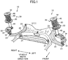
- FIG. 1 illustrates right and left front suspensions 10 (hereinafter, simply referred to as suspensions 10) as suspension devices for vehicles according to an exemplary embodiment.
- suspensions 10 right and left front suspensions 10
- the front and rear, left and right, and top and bottom of a vehicle body 1 will be simply referred to as the front and rear (or longitudinal direction), left and right (or width direction), and top and bottom (or vertical direction).
- Each suspension 10 is a strut suspension disposed between a wheel 30 (in this example, a front wheel which is a steering wheel) of a vehicle and the vehicle body 1.
- the suspension 10 includes a knuckle 35 that rotatably supports a hub 32 of the wheel 30 through a bearing 34, a lower arm 20 that connects the knuckle 35 to a subframe (sometimes called a suspension cross-member) 12 constituting a part of the vehicle body 1, and a strut 39.
- the subframe 12 extends in the vehicle width direction and is connected to, for example, right and left front side frames (not illustrated) of the vehicle body 1.
- the strut 39 is provided between the knuckle 35 and the vehicle body 1 (in this embodiment, a wheel housing 2 (see FIG. 3 )).
- the knuckle 35 has a first connected portion 36 connected to the damper 40 at its upper end, a second connected portion 37 connected to the lower arm 20 at its lower end, and a third connected portion 38 connected to a tie rod 6 at its rear end.
- the first to third connected portions 36 to 38 are disposed inside with respect to the hub 32 in the vehicle width direction.
- a separate knuckle arm extending rearward may be connected to the knuckle 35.
- the third connected portion 38 may be arranged on an end (rear end) of the knuckle arm.
- an inner portion of the lower arm 20 in the vehicle width direction extends in the vehicle's longitudinal direction, and the lower arm 20 curvedly extends outward in the vehicle width direction from a front end of the inner portion.
- the inner portion of the lower arm 20 in the vehicle width direction is connected to the subframe 12 through a pair of front and rear connecting portions 21 and 22.
- the lower arm 20 is supported by the subframe 12 so as to be rotatable about an axis extending in the vehicle's longitudinal direction at the front connecting portion 21, and supported by the subframe 12 so as to be rotatable about an axis extending in the vertical direction at the rear connecting portion 22.
- an outer end of the lower arm 20 in the vehicle width direction is connected to the second connected portion 37 of the knuckle 35 through a first ball joint 23.
- the knuckle 35 is accordingly connected to the subframe 12 (that is, the vehicle body 1) through the lower arm 20.
- the first ball joint 23 corresponds to a connecting portion of the lower arm 20 connecting to the knuckle 35.
- the tie rod 6 is disposed so as to extend in the vehicle width direction.
- An inner portion of the tie rod 6 in the vehicle width direction is connected to a steering gearbox 7 of a steering system.
- the tie rod 6 is therefore translated in the vehicle width direction in conjunction with a steering rack and other parts of the steering gearbox 7, in response to steering operation.
- An outer end of the tie rod 6 in the vehicle width direction is connected to a third connected portion 38 of the knuckle 35 through a second ball joint 24.
- the knuckle 35 is accordingly connected with the steering system (the steering gearbox 7) through the tie rod 6.
- the second ball joint 24 corresponds to a connecting portion of the tie rod 6 connecting to the knuckle 35.
- the second ball joint 24 is located in a rearward position of the first ball joint 23. In the steering neutral state, the second ball joint 24 is offset inward with respect to the first ball joint 23 in the vehicle width direction.
- the translational move of the tie rod 6 in the vehicle width direction in response to the steering operation causes the third connected portion 38 of the knuckle 35 to move in the vehicle width direction, whereby the wheel 30 supported by the knuckle 35 is steered.
- the strut 39 is mainly comprised of a coil spring 60 disposed between the wheel 30 and the vehicle body 1 (the wheel housing 2) to absorb impact on the wheel 30, and the damper 40 which absorbs vibration of the coil spring 60.
- the damper 40 is extendable and retractable between the wheel 30 and the vehicle body 1 (the wheel housing 2).
- the damper 40 is an extendable and retractable damper having a cylinder 41 and a piston rod 42. With the piston rod 42 sliding relative to the cylinder 41, the damper 40 extends and retracts in the direction of an axis C1 of the damper 40.
- the axis C1 of the damper 40 is inclined relative to the vertical direction. Specifically, the axis C1 of the damper 40 is inclined inward in the vehicle width direction toward the top of the vehicle (see FIG. 3 ) and inclined rearward toward the top of the vehicle (see FIG. 4 ).
- the cylinder 41 has its lower end coupled and fixed to the first connected portion 36 of the knuckle 35.
- a lower spring seat 50 is mounted on a portion near the upper end of the cylinder 41.
- the lower spring seat 50 is fixed to the outer peripheral surface of the cylinder 41, for example, by welding.
- a seat rubber 54 (see FIG. 5 ) is mounted on the upper surface of the lower spring seat 50.
- the piston rod 42 is upwardly projected from the cylinder 41.
- An upper mount 44 is mounted on the upper end of the piston rod 42.
- the upper mount 44 is fixed to the wheel housing 2 of the vehicle body 1, for example, with a bolt.
- the upper end of the damper 40 is accordingly connected to the vehicle body 1 through the upper mount 44.
- An upper spring seat 46 is mounted on the bottom of the upper mount 44.
- the upper spring seat 46 is attached to the upper end of the piston rod 42 through the upper mount 44. This configuration makes the distance between the upper spring seat 46 and the lower spring seat 50 variable in the axial direction of the damper 40, in response to extension and retraction of the damper 40.
- a seat rubber 48 is mounted on the lower surface of the upper spring seat 46.
- the piston rod 42 between the upper end of the cylinder 41 and the upper spring seat 46 is covered by, for example, an accordion dust cover 43.
- the coil spring 60 is disposed between the upper spring seat 46 and the lower spring seat 50.
- the seat rubber 48 is interposed between the coil spring 60 and the upper spring seat 46, and the seat rubber 54 is interposed between the coil spring 60 and the lower spring seat 50. This configuration contributes to reducing impact and thus reducing noise.
- the upper spring seat 46 and the lower spring seat 50 correspond to a pair of upper and lower spring supporters.
- the coil spring 60 is arranged to wind around the piston rod 42 and the dust cover 43 of the damper 40.
- the coil spring 60 is wound clockwise from its upper end toward its lower end. This winding direction is the same between the right and left struts 39.
- the right and left struts 39 may have the coil springs 60 each of which is wound counterclockwise from its upper end toward its lower end.
- the lower end portion of the coil spring 60 has a center P2 offset outward in the vehicle width direction and rearward in the vehicle's longitudinal direction with respect to a center P1 of the upper end portion. Further, at the vertical position of the center P2, the center P2 of the lower end portion of the coil spring 60 is offset outward in the vehicle width direction and rearward in the vehicle's longitudinal direction with respect to the axis C1 of the damper 40.
- the offset amounts of the center P2 of the lower end portion of the coil spring 60 with respect to the center P1 of the upper end portion in the vehicle width direction and in the vehicle's longitudinal direction are the same between the right and left struts 39.
- the offset amounts of the center P2 of the lower end portion of the coil spring 60, at the vertical position of the center P2, with respect to the axis C1 of the damper 40 in the vehicle width direction and the vehicle's longitudinal direction are the same between the right and left struts 39.
- the coil spring 60 as a whole is inclined inward in the vehicle width direction toward the top of the vehicle. Furthermore, as illustrated in FIG. 4 , the coil spring 60 as a whole is inclined frontward toward the top of the vehicle.
- the coil spring 60 has a load axis C2 along a direction inclined outward in the vehicle width direction and rearward in the vehicle's longitudinal direction, toward the bottom of the vehicle.
- the load axis C2 of the coil spring 60 is inclined outward in the vehicle width direction toward the bottom of the vehicle, like the axis C1 of the damper 40, but the load axis C2 of the coil spring 60 is inclined at a larger angle relative to the vertical direction than the axis C1 of the damper 40 is inclined relative to the vertical direction.
- the load axis C2 of the coil spring 60 is inclined rearward toward the bottom of the vehicle, unlike the axis C1 of the damper 40.
- the spring force of the coil spring 60 in such a posture described above may act on the lower spring seat 50 in a direction inclined outward in the vehicle width direction and rearward in the vehicle's longitudinal direction, toward the bottom of the vehicle, and on the upper spring seat 46 in a direction inclined inward in the vehicle width direction and frontward in the vehicle's longitudinal direction, toward the top of the vehicle.
- a load F2 (see FIG. 8 ) along a direction inclined inward in the vehicle width direction and frontward in the vehicle's longitudinal direction, toward the top of the vehicle, can thus be input to the upper end of the damper 40 from the coil spring 60 through the upper spring seat 46 and the upper mount 44.
- the line L1 is disposed along a direction inclined inward in the vehicle width direction toward the rear of the vehicle.
- a load is input to the hub 32 of the wheel 30 from the road surface on which the vehicle is traveling, such a load generates a moment M1 (in the right strut 39 in FIG. 2 , the moment M1 to rotate the knuckle 35 and the damper 40 clockwise when viewed from the front) to rotate the knuckle 35 and the damper 40 about a virtual axis along the line L1.
- a load F1 is input to the upper end of the damper 40 from the wheel housing 2 of the vehicle body 1 through the upper mount 44.
- the load F1 input to the upper end of the damper 40 from the vehicle body 1 acts in a direction inclined rearward toward the outside in the vehicle width direction.
- the load F2 input to the upper end of the damper 40 from the coil spring 60 acts in a direction inclined frontward toward the inside in the vehicle width direction.
- the load F1 from the vehicle body 1 is effectively offset by the load F2 from the coil spring 60.
- a bending moment acting on the damper 40 is effectively reduced, which can make the damper 40 operate more smoothly and improve comfort of a passenger on board the vehicle and increase stability of steering the vehicle.
- the upper surface of the lower spring seat 50 has recesses and projections which allow the seat rubber 54 to be positioned at a predetermined location.
- the seat rubber 54 is properly positioned by being placed on the lower spring seat 50.
- the coil spring 60 is positioned with its lower end placed in a groove of the seat rubber 54.
- the seat rubber 54 is substantially arcuate in plan view, and has a stopper 55 at an end thereof in the circumferential direction.
- the coil spring 60 is accurately positioned by being set on the seat rubber 54 with its lower end tip in contact with the stopper 55.
- the load axis C2 of the coil spring 60 is accordingly accurately disposed along the inclined direction described above, thereby reducing the bending moment acting on the damper 40.
- components, 40, 44, 46, 48, 50, 54, and 60 of the strut 39 are the same between the right and left struts 39.
- the right and left struts are usually arranged such that circumferential phases of the entire struts, including coil springs, are shifted 180 degrees from each other.
- the present embodiment is different from such conventional devices in the phase relation between the coil springs 60 of the right and left struts 39.
- FIG. 6 illustrating a first comparative example
- FIG. 7 illustrating a second comparative example
- FIG. 8 illustrating the configuration of the present embodiment.
- the first comparative example of FIG. 6 is configured such that the load axes of the coil springs 160 are arranged parallel with each other in the vehicle width direction when viewed in the vertical direction.
- the right strut 139A and a left strut 139B are arranged such that circumferential phases of the entire right and left struts 139A and 139B, including coil springs 160 and lower spring seats 150 to position the respective coil springs 160, are shifted 180 degrees from each other. That is, the right and left struts 139A and 139B are arranged in point symmetry in plan view, which allows the load axes to be arranged in the above-described manner.
- the offset amount D10 of the lower end tip 161 of the coil spring 160 with respect to an axis C10 of the damper 140 in the vehicle's longitudinal direction is the same between the right and left struts 139A and 139B.
- a spring force F10 of the coil spring 160 acting on the upper end of the damper 140 includes no component in the vehicle's longitudinal direction.
- the load F1 illustrated in FIG. 2 which acts in a direction inclined rearward toward the outside in the vehicle width direction, from the vehicle body 1, the load F1 cannot be offset by the spring force F10 of the coil spring 160.
- This configuration therefore has difficulty in effectively reducing the bending moment acting on the damper 140.
- FIG. 7 illustrates the second comparative example in which the right and left struts 139A and 139B of the first comparative example as a whole are moved clockwise by the same angle in top view.
- the phases of the right and left struts 139A and 139B are shifted 180 degrees from each other, and the offset amount D20 of the lower front end tip 161 of the coil spring 160 with respect to the axis C10 of the damper 140 in the vehicle's longitudinal direction is the same between the right and left struts 139A and 139B.
- the direction of the load axis of the coil spring 160 is inclined in the vehicle's longitudinal direction with respect to the vehicle width direction.
- the right strut 139A allows a spring force F20 of the coil spring 160 to act in a direction inclined rearward toward the top of the vehicle, and accordingly allows the load F1 from the vehicle body 1 to be offset by the spring force F20.
- the strut 39 on the right side will be referred to as a right strut 39A
- the strut 39 on the left side will be referred to as a left strut 39B.
- both of the right and left struts 39A and 39B are configured such that the respective load axes C2 (see FIG. 3 and FIG. 4 ) of the coil springs 60 are inclined frontward toward the top of the vehicle.
- This configuration allows, in each of the right and left struts 39A and 39B, the load F1 from the vehicle body 1 to be offset by the spring force (the load F2) of the coil spring 60, and is therefore capable of effectively reducing the bending moment acting on the damper 40.
- the load axes C2 of the coil springs 60 of the right strut 39A and the left strut 39B are bilaterally symmetric (with respect to the center line in the vehicle width direction) when viewed in both of the vehicle's longitudinal direction and the vertical direction.
- This configuration allows the spring force of the coil springs 60 of both of the right and left struts 39A and 39B to act, in a similar manner, on the respective upper ends of the dampers 40. Since the spring force of the coil spring 60 acts equally on the upper ends of the dampers 40 of the right and left struts 39A and 39B, the bending moment on the damper 40 is equally reduced in both of the struts 39.
- the circumferential phases of the entire right strut 39A and the entire left strut 39B are not shifted 180 degrees as in the conventional examples, but are shifted in a different manner.
- the right strut 39A and the left strut 39B are asymmetrically arranged in plan view.
- This asymmetric arrangement may be employed at least for the coil springs 60, the lower spring seats 50, and the seat rubbers 54 of the right and left struts 39A and 39B, and other components may be in point symmetric similarly to the first comparative example.
- the offset amounts D1 and D2 of the lower end tips 61 of the coil springs 60 with respect to the axes C1 of the dampers 40 in the vehicle's longitudinal direction, at the vertical positions where the lower end tips 61 of the coil springs 60 are located, are different between the right and left struts 39A and 39B.
- Such an asymmetric arrangement of the coil springs 60 of the right and left struts 39A and 39B can achieve an effective reduction of the bending moment on the dampers 40 of both of the right and left struts 39A and 39B.
- the same coil spring 60 can be used for each of the right and left struts 39A and 39B, which is beneficial in reducing the cost of parts compared with a case in which the right and left struts 39A and 39B use different coil springs.
- the same coil spring 60 means coil springs having, for example, the same winding direction, same shape, same size, and same spring characteristics.
- the axis C1 of the damper 40 is inclined inward in the vehicle width direction and rearward in the vehicle's longitudinal direction, toward the top of the vehicle.
- the present invention is further applicable to a configuration in which the axis C1 of the damper 40 is inclined in a direction different from the direction of the above embodiment with respect to the vertical direction, or a configuration in which the axis C1 is arranged along the vertical direction.
- the present invention is useful for a strut suspension device for vehicles with a damper and a coil spring.
Landscapes
- Engineering & Computer Science (AREA)
- Mechanical Engineering (AREA)
- Chemical & Material Sciences (AREA)
- Combustion & Propulsion (AREA)
- Transportation (AREA)
- Vehicle Body Suspensions (AREA)
Abstract
Description
- The present invention relates to a suspension device for vehicles disposed between a vehicle body and a wheel.
- Strut suspension devices for vehicles usually include a strut (a supporting pillar) consisting of a damper and a coil spring to support the vehicle body. Load input to a hub of a wheel of the vehicle from a road surface on which the vehicle is traveling is transmitted to the damper through a knuckle and other parts, which may cause a bending moment to act on the damper. The bending moment may increase frictional force at a sliding portion of the damper and thus keep the damper from smooth operation, which may decrease comfort of a passenger on board the vehicle and stability of steering the vehicle.
- Such a technique relating to a strut suspension device, as described in
Patent Document 1, is therefore well known that makes the load axis of a coil spring inclined outward in the vehicle width direction toward the bottom of the vehicle, with respect to the axis of the damper, and offsets the bending moment acting on the damper as described above with the spring force of the coil spring. - PATENT DOCUMENT 1: Japanese Unexamined Patent Publication No.
2003-326932 - In a strut front suspension as illustrated in
FIG. 9 , alower arm 120 connected to the vehicle body through a subframe (a suspension member) 112 and other parts, and atie rod 106 connected to a steering gearbox, have respective outer ends in the vehicle width direction connected to aknuckle 135, supporting the lower end of adamper 140, through connectingportions 123 and 124 (for example, ball joints). These connectingportions hub 132 of awheel 130 in the vehicle width direction and remote from each other at a certain interval in the vehicle's longitudinal direction. - This type of front suspension has the pair of front and rear connecting
portions hub 132 of thewheel 130 in the vehicle width direction. When load is input to thehub 132 of thewheel 130 from the road surface on which the vehicle is traveling, a moment M100 (inFIG. 9 , the moment M100 to turn theknuckle 135 and thedamper 140 clockwise when viewed from the front of the vehicle body) is generated to turn theknuckle 135 and thedamper 140 around a virtual axis extending along a virtual line L100 connecting between the pair of connectingportions - As in the example of
FIG. 9 , in the case in which theconnecting portion 124 close to the rear of the vehicle is disposed inside in the vehicle width direction with respect to the connectingportion 123 close to the front of the vehicle, the line L100 connecting between the pair of connectingportions damper 140 from the vehicle body, in a direction inclined rearward toward the outside of the vehicle in the vehicle width direction. - The load F100 input to the upper end of the
damper 140 therefore includes a component Fx in a direction toward the outside in the vehicle width direction and a component Fy in a direction toward the rear in the vehicle's longitudinal direction. - The above conventional configuration has a
coil spring 160 the load axis of which is inclined in the vehicle width direction with respect to the axis of thedamper 140, and this configuration is capable of offsetting the bending moment acting on thedamper 140 by the component Fx in the vehicle width direction of the load F100 input to the upper end of thedamper 140, by the spring force of thecoil spring 160. - In the conventional configuration, however, the load axis of the
coil spring 160 is not inclined in the vehicle's longitudinal direction with respect to the vertical direction of the vehicle. This configuration is therefore not capable of offsetting the bending moment acting on thedamper 140 by the component Fy in the vehicle's longitudinal direction of the load F100 input to the upper end of thedamper 140, by the spring force of thecoil spring 160. The conventional configuration therefore still has room for improvement to reduce the bending moment on the damper. - In view of the foregoing background, it is an object of the present invention to provide a suspension device for vehicles capable of further effectively reducing a bending moment acting on a damper of the suspension device and allowing the damper to operate smoothly.
- In order to achieve the above object, the present invention provides following first and second suspension devices for vehicles.
- A first suspension device for a vehicle includes a knuckle configured to support a wheel of the vehicle; a lower arm configured to connect the knuckle to a vehicle body of the vehicle; a tie rod configured to connect the knuckle to a steering system; a damper having an upper end connected to the vehicle body and a lower end connected to the knuckle, the damper being capable of extending and retracting in an axial direction of the damper; a pair of upper and lower spring supporters mounted on the damper such that a distance from each other is changed in the axial direction of the damper according to the extending and retracting of the damper; and a coil spring disposed between the pair of upper and lower spring supporters. Of a connecting portion of the lower arm for connection to the knuckle and a connecting portion of the tie rod for connection to the knuckle, one of the connecting portions which is close to a rear of the vehicle is offset inward in a vehicle width direction with respect to the other connecting portion which is close to a front of the vehicle, in a steering neutral state. A center of a lower end portion of the coil spring is offset outward in the vehicle width direction and rearward in a vehicle's longitudinal direction with respect to a center of an upper end portion of the coil spring.
- The center of the lower end portion of the coil spring is used herein as the central position in the vehicle width direction and in the vehicle's longitudinal direction of the lowermost winding of the coil spring. The center of the upper end portion of the coil spring is the central position in the vehicle width direction and in the vehicle's longitudinal direction of the uppermost winding of the coil spring.
- The center of the lower end portion of the coil spring is offset outward in the vehicle width direction and rearward in the vehicle's longitudinal direction with respect to the center of the upper end portion of the coil spring. This configuration allows spring force of the coil spring to act on the lower spring supporter in a direction inclined outward in the vehicle width direction and rearward in the vehicle's longitudinal direction, toward the bottom of the vehicle, and to act on the upper spring supporter in a direction inclined inward in the vehicle width direction and frontward in the vehicle's longitudinal direction, toward the top of the vehicle.
- When a load is input to the wheel from the road surface, and such a moment is generated that rotates the knuckle and the damper about a virtual axis extending along a virtual line connecting between the connecting portions of the lower arm and the tie rod for connection to the knuckle, a load is input to the upper end of the damper from the vehicle body in a direction inclined rearward in the vehicle's longitudinal direction toward the outside in the vehicle width direction. This load is effectively offset with the spring force of the above coil spring acting on the upper end of the damper through the upper spring supporter.
- This configuration can effectively keep the bending moment from acting on the damper, which allows the damper to operate smoothly. This configuration thus can improve comfort of a passenger on board the vehicle and increase stability of steering the vehicle.
- In an embodiment of the first suspension device for a vehicle, the center of the lower end portion of the coil spring is offset outward in the vehicle width direction and rearward in the vehicle's longitudinal direction with respect to the axis of the damper, at a vertical position of the center of the lower end portion in a vertical direction of the vehicle.
- As described above, the center of the lower end portion of the coil spring is offset outward in the vehicle width direction and rearward in the vehicle's longitudinal direction with respect to the axis of the damper, at the vertical position of the center in the vertical direction of the vehicle. Thus, even if the damper is arranged with its axis inclined rearward in the vehicle's longitudinal direction toward the top of the vehicle, the coil spring wound around the circumference of the damper is easily inclined frontward in the vehicle's longitudinal direction toward the top of the vehicle. This configuration therefore allows the spring force of the coil spring to easily act on the upper end of the damper in a direction inclined inward in the vehicle width direction and frontward in the vehicle's longitudinal direction, toward the top of the vehicle.
- In a different embodiment of the first suspension device for a vehicle, a strut comprised of the damper and the coil spring is mounted on each of wheels on right and left sides of the vehicle, and offset amounts of the center of the lower end portion of the coil spring with respect to the center of the upper end portion of the coil spring in the vehicle width direction and in the vehicle's longitudinal direction are the same between the struts on the right and left sides of the vehicle body.
- As described above, the offset amounts of the center of the lower end portion of the coil spring with respect to the center of the upper end portion of the coil spring in the vehicle width direction and in the vehicle's longitudinal direction are the same between the struts on the right and left sides of the vehicle body. This configuration allows the spring force of the coil springs to act equally on the upper ends of the dampers of the struts on the right and left side of the vehicle, and can effectively reduce the bending moment acting on the dampers.
- In the different embodiment, an offset amount of a lower end tip of the coil spring with respect to the axis of the damper in the vehicle's longitudinal direction may differ between the struts on the right and left sides of the vehicle body, at a vertical position of the lower end tip of the coil spring in the vertical direction of the vehicle.
- Although the amount of offset of the lower end tip of the coil spring to the axis of the damper in the vehicle's longitudinal direction differs between the struts on the right and left sides of the vehicle at the position of the lower end tip of the coil spring in the vertical direction of the vehicle, this asymmetric arrangement of the struts on the right and left sides of the vehicle can effectively reduce the bending moment acting on the dampers of the struts on the right and left sides of the vehicle in an equal manner.
- In the above different embodiment, the coil spring of the strut on the right side of the vehicle body and the coil spring of the strut on the left side of the vehicle body may be wound in a same direction from respective upper ends toward lower ends.
- The coil springs wound in the same direction can effectively reduce the bending moment acting on the dampers of the respective struts on the right and left sides of the vehicle in an equal manner.
- A second suspension device for vehicles includes: a knuckle configured to support a wheel of the vehicle; a lower arm configured to connect the knuckle to a vehicle body of the vehicle; a tie rod configured to connect the knuckle to a steering system; a damper having an upper end connected to the vehicle body and a lower end connected to the knuckle, the damper being capable of extending and retracting in an axial direction of the damper; a pair of upper and lower spring supporters mounted on the damper such that a distance from each other is changed in the axial direction of the damper according to the extending and retracting of the damper; and a coil spring disposed between the pair of upper and lower spring supporters. Of a connecting portion of the lower arm for connection to the knuckle and a connecting portion of the tie rod for connection to the knuckle, one of the connecting portions which is close to a rear of the vehicle is offset inward in a vehicle width direction with respect to the other connecting portion which is close to a front of the vehicle, in a steering neutral state. The coil spring has a load axis arranged along a direction inclined outward in the vehicle width direction and rearward in a vehicle's longitudinal direction, toward a bottom of the vehicle.
- The load axis of the coil spring is used herein as a virtual axis indicating the direction of load transferred between the pair of upper and lower spring supporters through the coil spring.
- As described above, the load axis of the coil spring is arranged along a direction inclined outward in the vehicle width direction and rearward in the vehicle's longitudinal direction, toward the bottom of the vehicle. This arrangement allows the spring force of the coil spring along a direction inclined inward in the vehicle width direction and frontward in the vehicle's longitudinal direction, toward the top of the vehicle, to act on the upper end of the damper through the upper spring supporter.
- If the moment is generated and a load is input to the upper end of the damper from the vehicle body in a direction inclined rearward in the vehicle's longitudinal direction toward the outside in the vehicle width direction, such load can be effectively offset by the spring force of the coil spring.
- That is, this configuration can effectively reduce the bending moment acting on the damper, which allows the damper to operate smoothly. This configuration can therefore improve comfort of a passenger on the vehicle and increase stability of steering the vehicle.
- In an embodiment of the second suspension device for a vehicle, a strut comprised of the damper and the coil spring is mounted on each of wheels on right and left sides of the vehicle body, and a load axis of the coil spring of the strut on the right side of the vehicle body and a load axis of the coil spring of the strut on the left side of the vehicle body are bilaterally symmetric when viewed in the vehicle's longitudinal direction and in a vertical direction of the vehicle.
- The load axes of the coil springs of the struts on the right and left sides of the vehicle are bilaterally symmetric when viewed in both of the vehicle's longitudinal direction and the vertical direction of the vehicle. This symmetric arrangement allows the spring force of the coil springs to act equally on the upper ends of the dampers of the struts on the right and left sides of the vehicle, and can effectively reduce the bending moment acting on the dampers.
- In the embodiment of the second suspension device for a vehicle, an offset amount of a lower end tip of the coil spring with respect to the axis of the damper in the vehicle's longitudinal direction may differ between the struts on the right and left sides of the vehicle body, at a vertical position of the lower end tip of the coil spring in the vertical direction of the vehicle.
- Although the amount of offset of the lower end tip of the coil spring to the axis of the damper in the vehicle's longitudinal direction differs between the struts on the right and left sides of the vehicle at the position of the lower end tip of the coil spring in the vertical direction of the vehicle, this asymmetric arrangement of the struts on the right and left sides of the vehicle can effectively reduce the bending moment acting on the dampers of the struts on the right and left sides of the vehicle in an equal manner.
- In the embodiment of the second suspension device for a vehicle, the coil spring of the strut on the right side of the vehicle body and the coil spring of the strut on the left side of the vehicle body may be wound in a same direction from respective upper ends toward lower ends.
- The coil springs wound in the same direction can effectively reduce the bending moment acting on the dampers of the respective struts on the right and left sides of the vehicle in an equal manner.
- As described above, a suspension device for a vehicle of the present invention is capable of effectively reducing the bending moment acting on a damper, which allows the damper to operate smoothly, and accordingly improves comfort of a passenger on board the vehicle and increases stability of steering the vehicle.
-
-
FIG. 1 is a perspective view of front suspensions as suspension devices for vehicles according to an exemplary embodiment. -
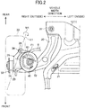
FIG. 2 is a plan view of the front suspension on the right side of the vehicle as viewed from above the vehicle. -
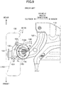
FIG. 3 is a front view of the front suspension on the right side of the vehicle as viewed from the front side of the vehicle. -
FIG. 4 is a side view of the front suspension on the right side of the vehicle as viewed from the right side of the vehicle. -
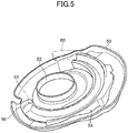
FIG. 5 is a perspective view that illustrates an exemplary configuration of a lower spring seat. -
FIG. 6 is a plan view of right and left lower spring seats and lower end portions of coil springs in a first comparative example as viewed from above the vehicle. -
FIG. 7 is a plan view of right and left lower spring seats and lower end portions of coil springs in a second comparative example as viewed from above the vehicle. -
FIG. 8 is a plan view of right and left lower spring seats and lower end portions of coil springs of this embodiment as viewed from above the vehicle. -
FIG. 9 is a plan view of an example conventional suspension device for vehicles. - Exemplary embodiments will now be described in detail below, with reference to the drawings.
-
FIG. 1 illustrates right and left front suspensions 10 (hereinafter, simply referred to as suspensions 10) as suspension devices for vehicles according to an exemplary embodiment. In the following description, the front and rear, left and right, and top and bottom of a vehicle body 1 (seeFIG. 1 to FIG. 3 ) will be simply referred to as the front and rear (or longitudinal direction), left and right (or width direction), and top and bottom (or vertical direction). - Each
suspension 10 is a strut suspension disposed between a wheel 30 (in this example, a front wheel which is a steering wheel) of a vehicle and thevehicle body 1. Thesuspension 10 includes aknuckle 35 that rotatably supports ahub 32 of thewheel 30 through abearing 34, alower arm 20 that connects theknuckle 35 to a subframe (sometimes called a suspension cross-member) 12 constituting a part of thevehicle body 1, and astrut 39. - The
subframe 12 extends in the vehicle width direction and is connected to, for example, right and left front side frames (not illustrated) of thevehicle body 1. Thestrut 39 is provided between theknuckle 35 and the vehicle body 1 (in this embodiment, a wheel housing 2 (seeFIG. 3 )). - As illustrated in
FIG. 2 to FIG. 4 , theknuckle 35 has a first connectedportion 36 connected to thedamper 40 at its upper end, a second connectedportion 37 connected to thelower arm 20 at its lower end, and a thirdconnected portion 38 connected to atie rod 6 at its rear end. The first to thirdconnected portions 36 to 38 are disposed inside with respect to thehub 32 in the vehicle width direction. - A separate knuckle arm extending rearward may be connected to the
knuckle 35. In this case, the thirdconnected portion 38 may be arranged on an end (rear end) of the knuckle arm. - As illustrated in
FIG. 1 andFIG. 2 , an inner portion of thelower arm 20 in the vehicle width direction extends in the vehicle's longitudinal direction, and thelower arm 20 curvedly extends outward in the vehicle width direction from a front end of the inner portion. - The inner portion of the
lower arm 20 in the vehicle width direction is connected to thesubframe 12 through a pair of front and rear connectingportions lower arm 20 is supported by thesubframe 12 so as to be rotatable about an axis extending in the vehicle's longitudinal direction at the front connectingportion 21, and supported by thesubframe 12 so as to be rotatable about an axis extending in the vertical direction at therear connecting portion 22. - As illustrated in
FIG. 3 andFIG. 4 , an outer end of thelower arm 20 in the vehicle width direction is connected to the second connectedportion 37 of theknuckle 35 through a first ball joint 23. Theknuckle 35 is accordingly connected to the subframe 12 (that is, the vehicle body 1) through thelower arm 20. The first ball joint 23 corresponds to a connecting portion of thelower arm 20 connecting to theknuckle 35. - As illustrated in
FIG. 2 andFIG. 3 , thetie rod 6 is disposed so as to extend in the vehicle width direction. An inner portion of thetie rod 6 in the vehicle width direction is connected to asteering gearbox 7 of a steering system. Thetie rod 6 is therefore translated in the vehicle width direction in conjunction with a steering rack and other parts of thesteering gearbox 7, in response to steering operation. - An outer end of the
tie rod 6 in the vehicle width direction is connected to a thirdconnected portion 38 of theknuckle 35 through a second ball joint 24. Theknuckle 35 is accordingly connected with the steering system (the steering gearbox 7) through thetie rod 6. The second ball joint 24 corresponds to a connecting portion of thetie rod 6 connecting to theknuckle 35. - The second ball joint 24 is located in a rearward position of the first ball joint 23. In the steering neutral state, the second ball joint 24 is offset inward with respect to the first ball joint 23 in the vehicle width direction.
- The translational move of the
tie rod 6 in the vehicle width direction in response to the steering operation causes the thirdconnected portion 38 of theknuckle 35 to move in the vehicle width direction, whereby thewheel 30 supported by theknuckle 35 is steered. - As illustrated in
FIG. 3 , thestrut 39 is mainly comprised of acoil spring 60 disposed between thewheel 30 and the vehicle body 1 (the wheel housing 2) to absorb impact on thewheel 30, and thedamper 40 which absorbs vibration of thecoil spring 60. Thedamper 40 is extendable and retractable between thewheel 30 and the vehicle body 1 (the wheel housing 2). - The
damper 40 is an extendable and retractable damper having acylinder 41 and apiston rod 42. With thepiston rod 42 sliding relative to thecylinder 41, thedamper 40 extends and retracts in the direction of an axis C1 of thedamper 40. - The axis C1 of the
damper 40 is inclined relative to the vertical direction. Specifically, the axis C1 of thedamper 40 is inclined inward in the vehicle width direction toward the top of the vehicle (seeFIG. 3 ) and inclined rearward toward the top of the vehicle (seeFIG. 4 ). - The
cylinder 41 has its lower end coupled and fixed to the first connectedportion 36 of theknuckle 35. Alower spring seat 50 is mounted on a portion near the upper end of thecylinder 41. Thelower spring seat 50 is fixed to the outer peripheral surface of thecylinder 41, for example, by welding. A seat rubber 54 (seeFIG. 5 ) is mounted on the upper surface of thelower spring seat 50. - The
piston rod 42 is upwardly projected from thecylinder 41. Anupper mount 44 is mounted on the upper end of thepiston rod 42. Theupper mount 44 is fixed to thewheel housing 2 of thevehicle body 1, for example, with a bolt. The upper end of thedamper 40 is accordingly connected to thevehicle body 1 through theupper mount 44. - An
upper spring seat 46 is mounted on the bottom of theupper mount 44. Theupper spring seat 46 is attached to the upper end of thepiston rod 42 through theupper mount 44. This configuration makes the distance between theupper spring seat 46 and thelower spring seat 50 variable in the axial direction of thedamper 40, in response to extension and retraction of thedamper 40. Aseat rubber 48 is mounted on the lower surface of theupper spring seat 46. - The
piston rod 42 between the upper end of thecylinder 41 and theupper spring seat 46 is covered by, for example, anaccordion dust cover 43. - The
coil spring 60 is disposed between theupper spring seat 46 and thelower spring seat 50. Theseat rubber 48 is interposed between thecoil spring 60 and theupper spring seat 46, and theseat rubber 54 is interposed between thecoil spring 60 and thelower spring seat 50. This configuration contributes to reducing impact and thus reducing noise. Theupper spring seat 46 and thelower spring seat 50 correspond to a pair of upper and lower spring supporters. - The
coil spring 60 is arranged to wind around thepiston rod 42 and thedust cover 43 of thedamper 40. In the illustrated example, thecoil spring 60 is wound clockwise from its upper end toward its lower end. This winding direction is the same between the right and left struts 39. The right and leftstruts 39 may have the coil springs 60 each of which is wound counterclockwise from its upper end toward its lower end. - As illustrated in
FIG. 3 andFIG. 4 , the lower end portion of thecoil spring 60 has a center P2 offset outward in the vehicle width direction and rearward in the vehicle's longitudinal direction with respect to a center P1 of the upper end portion. Further, at the vertical position of the center P2, the center P2 of the lower end portion of thecoil spring 60 is offset outward in the vehicle width direction and rearward in the vehicle's longitudinal direction with respect to the axis C1 of thedamper 40. - The offset amounts of the center P2 of the lower end portion of the
coil spring 60 with respect to the center P1 of the upper end portion in the vehicle width direction and in the vehicle's longitudinal direction are the same between the right and left struts 39. Likewise, the offset amounts of the center P2 of the lower end portion of thecoil spring 60, at the vertical position of the center P2, with respect to the axis C1 of thedamper 40 in the vehicle width direction and the vehicle's longitudinal direction are the same between the right and left struts 39. - As illustrated in
FIG. 3 , thecoil spring 60 as a whole is inclined inward in the vehicle width direction toward the top of the vehicle. Furthermore, as illustrated inFIG. 4 , thecoil spring 60 as a whole is inclined frontward toward the top of the vehicle. - As illustrated in
FIG. 3 andFIG. 4 , thecoil spring 60 has a load axis C2 along a direction inclined outward in the vehicle width direction and rearward in the vehicle's longitudinal direction, toward the bottom of the vehicle. As illustrated inFIG. 3 , with regard to inclination in the vehicle width direction relative to the vertical direction, the load axis C2 of thecoil spring 60 is inclined outward in the vehicle width direction toward the bottom of the vehicle, like the axis C1 of thedamper 40, but the load axis C2 of thecoil spring 60 is inclined at a larger angle relative to the vertical direction than the axis C1 of thedamper 40 is inclined relative to the vertical direction. With regard to inclination in the vehicle's longitudinal direction relative to the vertical direction, as illustrated inFIG. 4 , the load axis C2 of thecoil spring 60 is inclined rearward toward the bottom of the vehicle, unlike the axis C1 of thedamper 40. - The spring force of the
coil spring 60 in such a posture described above may act on thelower spring seat 50 in a direction inclined outward in the vehicle width direction and rearward in the vehicle's longitudinal direction, toward the bottom of the vehicle, and on theupper spring seat 46 in a direction inclined inward in the vehicle width direction and frontward in the vehicle's longitudinal direction, toward the top of the vehicle. - A load F2 (see
FIG. 8 ) along a direction inclined inward in the vehicle width direction and frontward in the vehicle's longitudinal direction, toward the top of the vehicle, can thus be input to the upper end of thedamper 40 from thecoil spring 60 through theupper spring seat 46 and theupper mount 44. - As illustrated in
FIG. 2 , provided that the center of the first ball joint 23 and the center of the second ball joint 24 are connected by a virtual line L1, the line L1 is disposed along a direction inclined inward in the vehicle width direction toward the rear of the vehicle. - Thus, if a load is input to the
hub 32 of thewheel 30 from the road surface on which the vehicle is traveling, such a load generates a moment M1 (in theright strut 39 inFIG. 2 , the moment M1 to rotate theknuckle 35 and thedamper 40 clockwise when viewed from the front) to rotate theknuckle 35 and thedamper 40 about a virtual axis along the line L1. At this moment, a load F1 is input to the upper end of thedamper 40 from thewheel housing 2 of thevehicle body 1 through theupper mount 44. - The load F1 input to the upper end of the
damper 40 from thevehicle body 1 acts in a direction inclined rearward toward the outside in the vehicle width direction. On the other hand, the load F2 input to the upper end of thedamper 40 from the coil spring 60 (the upward load of an arrow indicating both upward and downward directions inFIG. 8 ) acts in a direction inclined frontward toward the inside in the vehicle width direction. Thus, the load F1 from thevehicle body 1 is effectively offset by the load F2 from thecoil spring 60. - According to this embodiment, a bending moment acting on the
damper 40 is effectively reduced, which can make thedamper 40 operate more smoothly and improve comfort of a passenger on board the vehicle and increase stability of steering the vehicle. - As illustrated in
FIG. 5 , the upper surface of thelower spring seat 50 has recesses and projections which allow theseat rubber 54 to be positioned at a predetermined location. Theseat rubber 54 is properly positioned by being placed on thelower spring seat 50. Thecoil spring 60 is positioned with its lower end placed in a groove of theseat rubber 54. - The
seat rubber 54 is substantially arcuate in plan view, and has astopper 55 at an end thereof in the circumferential direction. Thecoil spring 60 is accurately positioned by being set on theseat rubber 54 with its lower end tip in contact with thestopper 55. The load axis C2 of thecoil spring 60 is accordingly accurately disposed along the inclined direction described above, thereby reducing the bending moment acting on thedamper 40. - In this embodiment, similarly to conventional suspension devices, components, 40, 44, 46, 48, 50, 54, and 60 of the
strut 39 are the same between the right and left struts 39. In conventional suspension devices, the right and left struts are usually arranged such that circumferential phases of the entire struts, including coil springs, are shifted 180 degrees from each other. The present embodiment is different from such conventional devices in the phase relation between the coil springs 60 of the right and left struts 39. - The configuration relating to the phases of the coil springs 60 will now be described with reference to
FIG. 6 illustrating a first comparative example,FIG. 7 illustrating a second comparative example, andFIG. 8 illustrating the configuration of the present embodiment. - Similarly to the generally known strut suspensions, the first comparative example of
FIG. 6 is configured such that the load axes of the coil springs 160 are arranged parallel with each other in the vehicle width direction when viewed in the vertical direction. - In the first comparative example, the
right strut 139A and aleft strut 139B are arranged such that circumferential phases of the entire right and leftstruts coil springs 160 andlower spring seats 150 to position therespective coil springs 160, are shifted 180 degrees from each other. That is, the right and leftstruts - In this arrangement, the offset amount D10 of the
lower end tip 161 of thecoil spring 160 with respect to an axis C10 of thedamper 140 in the vehicle's longitudinal direction is the same between the right and leftstruts - However, in the first comparative example, a spring force F10 of the
coil spring 160 acting on the upper end of thedamper 140 includes no component in the vehicle's longitudinal direction. When the upper end of thedamper 140 receives the load F1 illustrated inFIG. 2 , which acts in a direction inclined rearward toward the outside in the vehicle width direction, from thevehicle body 1, the load F1 cannot be offset by the spring force F10 of thecoil spring 160. This configuration therefore has difficulty in effectively reducing the bending moment acting on thedamper 140. -
FIG. 7 illustrates the second comparative example in which the right and leftstruts struts front end tip 161 of thecoil spring 160 with respect to the axis C10 of thedamper 140 in the vehicle's longitudinal direction is the same between the right and leftstruts - In the second comparative example, the direction of the load axis of the
coil spring 160 is inclined in the vehicle's longitudinal direction with respect to the vehicle width direction. In this case, theright strut 139A allows a spring force F20 of thecoil spring 160 to act in a direction inclined rearward toward the top of the vehicle, and accordingly allows the load F1 from thevehicle body 1 to be offset by the spring force F20. - On the other hand, with regard to the
left strut 139B, the load F1 from thevehicle body 1 cannot be offset by the spring force F30 because a spring force F30 of thecoil spring 160 acts in a direction inclined rearward toward the top of the vehicle. This configuration therefore has difficulty in effectively reducing the bending moment acting on thedamper 140. - The configuration of the present embodiment illustrated in
FIG. 8 will now be described. In the following description, thestrut 39 on the right side will be referred to as aright strut 39A, and thestrut 39 on the left side will be referred to as aleft strut 39B. - In the present embodiment, both of the right and left
struts FIG. 3 andFIG. 4 ) of the coil springs 60 are inclined frontward toward the top of the vehicle. This configuration allows, in each of the right and leftstruts vehicle body 1 to be offset by the spring force (the load F2) of thecoil spring 60, and is therefore capable of effectively reducing the bending moment acting on thedamper 40. - In this embodiment, the load axes C2 of the coil springs 60 of the
right strut 39A and theleft strut 39B are bilaterally symmetric (with respect to the center line in the vehicle width direction) when viewed in both of the vehicle's longitudinal direction and the vertical direction. This configuration allows the spring force of the coil springs 60 of both of the right and leftstruts dampers 40. Since the spring force of thecoil spring 60 acts equally on the upper ends of thedampers 40 of the right and leftstruts damper 40 is equally reduced in both of thestruts 39. - In order to achieve the above arrangements of the load axes C2 of the coil springs 60, the circumferential phases of the entire
right strut 39A and the entireleft strut 39B are not shifted 180 degrees as in the conventional examples, but are shifted in a different manner. In other words, theright strut 39A and theleft strut 39B are asymmetrically arranged in plan view. - This asymmetric arrangement may be employed at least for the coil springs 60, the
lower spring seats 50, and the seat rubbers 54 of the right and leftstruts - In the present embodiment, the offset amounts D1 and D2 of the
lower end tips 61 of the coil springs 60 with respect to the axes C1 of thedampers 40 in the vehicle's longitudinal direction, at the vertical positions where thelower end tips 61 of the coil springs 60 are located, are different between the right and leftstruts struts dampers 40 of both of the right and leftstruts - Furthermore, in achieving the above configuration, the
same coil spring 60 can be used for each of the right and leftstruts struts same coil spring 60 means coil springs having, for example, the same winding direction, same shape, same size, and same spring characteristics. - The present invention is not limited to the above embodiment, and any substitution can be made without departing from the spirit of the appended claims.
- For example, in the above embodiment, the axis C1 of the
damper 40 is inclined inward in the vehicle width direction and rearward in the vehicle's longitudinal direction, toward the top of the vehicle. The present invention is further applicable to a configuration in which the axis C1 of thedamper 40 is inclined in a direction different from the direction of the above embodiment with respect to the vertical direction, or a configuration in which the axis C1 is arranged along the vertical direction. - The above embodiment is a mere example, and limited interpretation of the scope of the present invention is not allowed. The scope of the present invention is determined by the appended claims, and modifications and changes included in the equivalent of the appended claims are all included in the scope of the present invention.
- As described above, the present invention is useful for a strut suspension device for vehicles with a damper and a coil spring.
-
- 1
- Vehicle Body
- 6
- Tie Rod
- 7
- Steering Gearbox of Steering System
- 10
- Front Suspension (Suspension Device for Vehicles)
- 20
- Lower Arm
- 23
- First Ball Joint (Connecting Portion of Lower Arm Connecting to Knuckle)
- 24
- Second Ball Joint (Connecting portion of Tie Rod Connecting to Knuckle)
- 30
- Wheel (Front Wheel, Steering Wheel)
- 35
- Knuckle
- 39
- Strut
- 40
- Damper
- 46
- Upper Spring Seat (Upper Spring Supporter)
- 50
- Lower Spring Seat (Lower Spring Supporter)
- 60
- Coil Spring
- 61
- Lower End Tip of Coil Spring
- C1
- Axis of Damper
- C2
- Load Axis of Coil Spring
- P1
- Center of Upper End Portion of Coil Spring
- P2
- Center of Lower End Portion of Coil Spring
Claims (9)
- A suspension device for a vehicle, comprising:a knuckle configured to support a wheel of the vehicle;a lower arm configured to connect the knuckle to a vehicle body of the vehicle;a tie rod configured to connect the knuckle to a steering system;a damper having an upper end connected to the vehicle body and a lower end connected to the knuckle, the damper being capable of extending and retracting in an axial direction of the damper;a pair of upper and lower spring supporters mounted on the damper such that a distance from each other is changed in the axial direction of the damper according to the extending and retracting of the damper; anda coil spring disposed between the pair of upper and lower spring supporters, whereinof a connecting portion of the lower arm for connection to the knuckle and a connecting portion of the tie rod for connection to the knuckle, one of the connecting portions which is close to a rear of the vehicle is offset inward in a vehicle width direction with respect to the other connecting portion which is close to a front of the vehicle, in a steering neutral state, anda center of a lower end portion of the coil spring is offset outward in the vehicle width direction and rearward in a vehicle's longitudinal direction with respect to a center of an upper end portion of the coil spring.
- The suspension device of claim 1, wherein
the center of the lower end portion of the coil spring is offset outward in the vehicle width direction and rearward in the vehicle's longitudinal direction with respect to the axis of the damper, at a vertical position of the center of the lower end portion in a vertical direction of the vehicle. - The suspension device of claim 1 or 2, wherein
a strut comprised of the damper and the coil spring is mounted on each of wheels on right and left sides of the vehicle, and
offset amounts of the center of the lower end portion of the coil spring with respect to the center of the upper end portion of the coil spring in the vehicle width direction and in the vehicle's longitudinal direction are the same between the struts on the right and left sides of the vehicle body. - The suspension device of claim 3, wherein
an offset amount of a lower end of the coil spring with respect to the axis of the damper in the vehicle's longitudinal direction differs between the struts on the right and left sides of the vehicle body, at a vertical position of the lower end of the coil spring in the vertical direction of the vehicle. - The suspension device of claim 3 or 4, wherein
the coil spring of the strut on the right side of the vehicle body and the coil spring of the strut on the left side of the vehicle body are wound in a same direction from respective upper ends toward lower ends. - A suspension device for a vehicle, comprising:a knuckle configured to support a wheel of the vehicle;a lower arm configured to connect the knuckle to a vehicle body of the vehicle;a tie rod configured to connect the knuckle to a steering system;a damper having an upper end connected to the vehicle body and a lower end connected to the knuckle, the damper being capable of extending and retracting in an axial direction of the damper;a pair of upper and lower spring supporters mounted on the damper such that a distance from each other is changed in the axial direction of the damper according to the extending and retracting of the damper; anda coil spring disposed between the pair of upper and lower spring supporters, whereinof a connecting portion of the lower arm for connection to the knuckle and a connecting portion of the tie rod for connection to the knuckle, one of the connecting portions which is close to a rear of the vehicle is offset inward in a vehicle width direction with respect to the other connecting portion which is close to a front of the vehicle, in a steering neutral state, andthe coil spring has a load axis arranged along a direction inclined outward in the vehicle width direction and rearward in a vehicle's longitudinal direction, toward a bottom of the vehicle.
- The suspension device of claim 6, wherein
a strut comprised of the damper and the coil spring is mounted on each of wheels on right and left sides of the vehicle body, and
a load axis of the coil spring of the strut on the right side of the vehicle body and a load axis of the coil spring of the strut on the left side of the vehicle body are bilaterally symmetric when viewed in the vehicle's longitudinal direction and in a vertical direction of the vehicle. - The suspension device of claim 7, wherein
an offset amount of a lower end tip of the coil spring with respect to the axis of the damper in the vehicle's longitudinal direction differs between the struts on the right and left sides of the vehicle body, at a vertical position of the lower end tip of the coil spring in the vertical direction of the vehicle. - The suspension device of claim 7 or 8, wherein
the coil spring of the strut on the right side of the vehicle body and the coil spring of the strut on the left side of the vehicle body are wound in a same direction from respective upper ends toward lower ends.
Applications Claiming Priority (2)
| Application Number | Priority Date | Filing Date | Title |
|---|---|---|---|
| JP2016225791A JP6332417B2 (en) | 2016-11-21 | 2016-11-21 | Vehicle suspension system |
| PCT/JP2017/039527 WO2018092588A1 (en) | 2016-11-21 | 2017-11-01 | Suspension device for vehicles |
Publications (3)
| Publication Number | Publication Date |
|---|---|
| EP3530499A1 true EP3530499A1 (en) | 2019-08-28 |
| EP3530499A4 EP3530499A4 (en) | 2020-04-15 |
| EP3530499B1 EP3530499B1 (en) | 2021-04-14 |
Family
ID=62145366
Family Applications (1)
| Application Number | Title | Priority Date | Filing Date |
|---|---|---|---|
| EP17872081.9A Active EP3530499B1 (en) | 2016-11-21 | 2017-11-01 | Suspension device for vehicles |
Country Status (5)
| Country | Link |
|---|---|
| US (1) | US10981426B2 (en) |
| EP (1) | EP3530499B1 (en) |
| JP (1) | JP6332417B2 (en) |
| CN (1) | CN109963731B (en) |
| WO (1) | WO2018092588A1 (en) |
Families Citing this family (1)
| Publication number | Priority date | Publication date | Assignee | Title |
|---|---|---|---|---|
| DE102018220235A1 (en) * | 2018-11-26 | 2020-05-28 | Ford Global Technologies, Llc | Independent wheel suspension for a motor vehicle |
Family Cites Families (16)
| Publication number | Priority date | Publication date | Assignee | Title |
|---|---|---|---|---|
| GB1237938A (en) * | 1967-10-28 | 1971-07-07 | ||
| JPS4634275Y1 (en) | 1967-10-28 | 1971-11-26 | ||
| JP2714969B2 (en) * | 1989-01-13 | 1998-02-16 | マツダ株式会社 | Automotive suspension equipment |
| JPH03112708A (en) * | 1989-09-27 | 1991-05-14 | Mazda Motor Corp | Suspension device for automobile |
| JPH09300932A (en) * | 1996-05-20 | 1997-11-25 | Toyota Motor Corp | Suspension device |
| JPH1148728A (en) * | 1997-07-31 | 1999-02-23 | Nissan Motor Co Ltd | Suspension device for steering wheel |
| JPH1148729A (en) * | 1997-07-31 | 1999-02-23 | Nissan Motor Co Ltd | Suspension device |
| FR2804376A1 (en) * | 2000-02-01 | 2001-08-03 | Michelin Ets | COMPENSATION METHOD FOR DRAWING A VEHICLE EQUIPPED WITH MAC PHERSON SUSPENSION AND FORCE LEG FOR COMPENSATION |
| JP2002178736A (en) * | 2000-12-14 | 2002-06-26 | Chuo Spring Co Ltd | Suspension coiled spring for automobile and strut type suspension device equipped with the same |
| JP2003326932A (en) | 2002-05-09 | 2003-11-19 | Nok Corp | Strut type suspension |
| JP4254599B2 (en) * | 2004-04-01 | 2009-04-15 | トヨタ自動車株式会社 | Strut suspension |
| US7513514B1 (en) * | 2004-10-29 | 2009-04-07 | Niwot Corporation | Adjustable ball joint connection assembly |
| JP5151770B2 (en) * | 2007-11-26 | 2013-02-27 | 日産自動車株式会社 | Lower spring seat mounting structure and lower spring seat |
| JP5161723B2 (en) * | 2008-10-03 | 2013-03-13 | 本田技研工業株式会社 | Stabilizer mounting structure |
| KR101448761B1 (en) | 2013-08-20 | 2014-10-08 | 현대자동차 주식회사 | Caster active geometry control system |
| JP2015174514A (en) * | 2014-03-14 | 2015-10-05 | 富士重工業株式会社 | Vehicle body structure |
-
2016
- 2016-11-21 JP JP2016225791A patent/JP6332417B2/en active Active
-
2017
- 2017-11-01 US US16/462,923 patent/US10981426B2/en active Active
- 2017-11-01 CN CN201780071678.0A patent/CN109963731B/en active Active
- 2017-11-01 EP EP17872081.9A patent/EP3530499B1/en active Active
- 2017-11-01 WO PCT/JP2017/039527 patent/WO2018092588A1/en unknown
Also Published As
| Publication number | Publication date |
|---|---|
| EP3530499A4 (en) | 2020-04-15 |
| CN109963731A (en) | 2019-07-02 |
| EP3530499B1 (en) | 2021-04-14 |
| CN109963731B (en) | 2022-06-17 |
| US10981426B2 (en) | 2021-04-20 |
| JP6332417B2 (en) | 2018-05-30 |
| JP2018083439A (en) | 2018-05-31 |
| US20190322149A1 (en) | 2019-10-24 |
| WO2018092588A1 (en) | 2018-05-24 |
Similar Documents
| Publication | Publication Date | Title |
|---|---|---|
| US9162546B2 (en) | Multilink rear axle for a motor vehicle | |
| JP4460831B2 (en) | Vehicle wheel suspension system | |
| US8408559B1 (en) | Active geometry control suspension system | |
| US11192422B2 (en) | Suspension device for vehicles | |
| US20150123371A1 (en) | Coupled torsion beam axle type suspension system | |
| US10744833B2 (en) | Independent suspension | |
| US10065472B2 (en) | Dual bearing strut assemblies and vehicle suspension systems with dual bearing strut assemblies | |
| US20160297269A1 (en) | Vehicle wheel suspension | |
| AU2016296919B2 (en) | Pneumatic axle suspension for a rear axle of a vehicle | |
| US20120175857A1 (en) | Vehicle Suspension System | |
| US8596647B2 (en) | Active roll control system | |
| EP3530499B1 (en) | Suspension device for vehicles | |
| GB2582330A (en) | Steering axle assembly | |
| JP5790865B2 (en) | Vehicle suspension system | |
| JP2011079474A (en) | Vehicular suspension device | |
| JP6497343B2 (en) | Vehicle suspension structure | |
| JP6171691B2 (en) | Suspension device for steered wheels | |
| JP2003118345A (en) | Strut type suspension device | |
| JP4701947B2 (en) | Strut suspension for steering wheels | |
| JP2003267021A (en) | Strut type suspension device | |
| JP4743235B2 (en) | Strut suspension | |
| JP5454509B2 (en) | Rear suspension device | |
| JP2007190943A (en) | Suspension device |
Legal Events
| Date | Code | Title | Description |
|---|---|---|---|
| STAA | Information on the status of an ep patent application or granted ep patent |
Free format text: STATUS: THE INTERNATIONAL PUBLICATION HAS BEEN MADE |
|
| PUAI | Public reference made under article 153(3) epc to a published international application that has entered the european phase |
Free format text: ORIGINAL CODE: 0009012 |
|
| STAA | Information on the status of an ep patent application or granted ep patent |
Free format text: STATUS: REQUEST FOR EXAMINATION WAS MADE |
|
| 17P | Request for examination filed |
Effective date: 20190524 |
|
| AK | Designated contracting states |
Kind code of ref document: A1 Designated state(s): AL AT BE BG CH CY CZ DE DK EE ES FI FR GB GR HR HU IE IS IT LI LT LU LV MC MK MT NL NO PL PT RO RS SE SI SK SM TR |
|
| AX | Request for extension of the european patent |
Extension state: BA ME |
|
| DAV | Request for validation of the european patent (deleted) | ||
| DAX | Request for extension of the european patent (deleted) | ||
| A4 | Supplementary search report drawn up and despatched |
Effective date: 20200312 |
|
| RIC1 | Information provided on ipc code assigned before grant |
Ipc: B60G 15/06 20060101AFI20200306BHEP Ipc: B60G 11/16 20060101ALI20200306BHEP Ipc: B60G 3/28 20060101ALI20200306BHEP |
|
| RIC1 | Information provided on ipc code assigned before grant |
Ipc: B60G 3/28 20060101ALI20201016BHEP Ipc: B60G 15/06 20060101AFI20201016BHEP Ipc: B60G 11/16 20060101ALI20201016BHEP |
|
| GRAP | Despatch of communication of intention to grant a patent |
Free format text: ORIGINAL CODE: EPIDOSNIGR1 |
|
| STAA | Information on the status of an ep patent application or granted ep patent |
Free format text: STATUS: GRANT OF PATENT IS INTENDED |
|
| INTG | Intention to grant announced |
Effective date: 20201127 |
|
| GRAS | Grant fee paid |
Free format text: ORIGINAL CODE: EPIDOSNIGR3 |
|
| GRAA | (expected) grant |
Free format text: ORIGINAL CODE: 0009210 |
|
| STAA | Information on the status of an ep patent application or granted ep patent |
Free format text: STATUS: THE PATENT HAS BEEN GRANTED |
|
| AK | Designated contracting states |
Kind code of ref document: B1 Designated state(s): AL AT BE BG CH CY CZ DE DK EE ES FI FR GB GR HR HU IE IS IT LI LT LU LV MC MK MT NL NO PL PT RO RS SE SI SK SM TR |
|
| REG | Reference to a national code |
Ref country code: GB Ref legal event code: FG4D |
|
| REG | Reference to a national code |
Ref country code: CH Ref legal event code: EP |
|
| REG | Reference to a national code |
Ref country code: DE Ref legal event code: R096 Ref document number: 602017036891 Country of ref document: DE |
|
| REG | Reference to a national code |
Ref country code: IE Ref legal event code: FG4D |
|
| REG | Reference to a national code |
Ref country code: AT Ref legal event code: REF Ref document number: 1382032 Country of ref document: AT Kind code of ref document: T Effective date: 20210515 |
|
| REG | Reference to a national code |
Ref country code: LT Ref legal event code: MG9D |
|
| REG | Reference to a national code |
Ref country code: AT Ref legal event code: MK05 Ref document number: 1382032 Country of ref document: AT Kind code of ref document: T Effective date: 20210414 |
|
| REG | Reference to a national code |
Ref country code: NL Ref legal event code: MP Effective date: 20210414 |
|
| PG25 | Lapsed in a contracting state [announced via postgrant information from national office to epo] |
Ref country code: LT Free format text: LAPSE BECAUSE OF FAILURE TO SUBMIT A TRANSLATION OF THE DESCRIPTION OR TO PAY THE FEE WITHIN THE PRESCRIBED TIME-LIMIT Effective date: 20210414 Ref country code: FI Free format text: LAPSE BECAUSE OF FAILURE TO SUBMIT A TRANSLATION OF THE DESCRIPTION OR TO PAY THE FEE WITHIN THE PRESCRIBED TIME-LIMIT Effective date: 20210414 Ref country code: NL Free format text: LAPSE BECAUSE OF FAILURE TO SUBMIT A TRANSLATION OF THE DESCRIPTION OR TO PAY THE FEE WITHIN THE PRESCRIBED TIME-LIMIT Effective date: 20210414 Ref country code: AT Free format text: LAPSE BECAUSE OF FAILURE TO SUBMIT A TRANSLATION OF THE DESCRIPTION OR TO PAY THE FEE WITHIN THE PRESCRIBED TIME-LIMIT Effective date: 20210414 Ref country code: BG Free format text: LAPSE BECAUSE OF FAILURE TO SUBMIT A TRANSLATION OF THE DESCRIPTION OR TO PAY THE FEE WITHIN THE PRESCRIBED TIME-LIMIT Effective date: 20210714 Ref country code: HR Free format text: LAPSE BECAUSE OF FAILURE TO SUBMIT A TRANSLATION OF THE DESCRIPTION OR TO PAY THE FEE WITHIN THE PRESCRIBED TIME-LIMIT Effective date: 20210414 |
|
| PG25 | Lapsed in a contracting state [announced via postgrant information from national office to epo] |
Ref country code: LV Free format text: LAPSE BECAUSE OF FAILURE TO SUBMIT A TRANSLATION OF THE DESCRIPTION OR TO PAY THE FEE WITHIN THE PRESCRIBED TIME-LIMIT Effective date: 20210414 Ref country code: NO Free format text: LAPSE BECAUSE OF FAILURE TO SUBMIT A TRANSLATION OF THE DESCRIPTION OR TO PAY THE FEE WITHIN THE PRESCRIBED TIME-LIMIT Effective date: 20210714 Ref country code: PL Free format text: LAPSE BECAUSE OF FAILURE TO SUBMIT A TRANSLATION OF THE DESCRIPTION OR TO PAY THE FEE WITHIN THE PRESCRIBED TIME-LIMIT Effective date: 20210414 Ref country code: PT Free format text: LAPSE BECAUSE OF FAILURE TO SUBMIT A TRANSLATION OF THE DESCRIPTION OR TO PAY THE FEE WITHIN THE PRESCRIBED TIME-LIMIT Effective date: 20210816 Ref country code: SE Free format text: LAPSE BECAUSE OF FAILURE TO SUBMIT A TRANSLATION OF THE DESCRIPTION OR TO PAY THE FEE WITHIN THE PRESCRIBED TIME-LIMIT Effective date: 20210414 Ref country code: RS Free format text: LAPSE BECAUSE OF FAILURE TO SUBMIT A TRANSLATION OF THE DESCRIPTION OR TO PAY THE FEE WITHIN THE PRESCRIBED TIME-LIMIT Effective date: 20210414 Ref country code: GR Free format text: LAPSE BECAUSE OF FAILURE TO SUBMIT A TRANSLATION OF THE DESCRIPTION OR TO PAY THE FEE WITHIN THE PRESCRIBED TIME-LIMIT Effective date: 20210715 Ref country code: IS Free format text: LAPSE BECAUSE OF FAILURE TO SUBMIT A TRANSLATION OF THE DESCRIPTION OR TO PAY THE FEE WITHIN THE PRESCRIBED TIME-LIMIT Effective date: 20210814 |
|
| REG | Reference to a national code |
Ref country code: DE Ref legal event code: R097 Ref document number: 602017036891 Country of ref document: DE |
|
| PG25 | Lapsed in a contracting state [announced via postgrant information from national office to epo] |
Ref country code: SK Free format text: LAPSE BECAUSE OF FAILURE TO SUBMIT A TRANSLATION OF THE DESCRIPTION OR TO PAY THE FEE WITHIN THE PRESCRIBED TIME-LIMIT Effective date: 20210414 Ref country code: SM Free format text: LAPSE BECAUSE OF FAILURE TO SUBMIT A TRANSLATION OF THE DESCRIPTION OR TO PAY THE FEE WITHIN THE PRESCRIBED TIME-LIMIT Effective date: 20210414 Ref country code: ES Free format text: LAPSE BECAUSE OF FAILURE TO SUBMIT A TRANSLATION OF THE DESCRIPTION OR TO PAY THE FEE WITHIN THE PRESCRIBED TIME-LIMIT Effective date: 20210414 Ref country code: EE Free format text: LAPSE BECAUSE OF FAILURE TO SUBMIT A TRANSLATION OF THE DESCRIPTION OR TO PAY THE FEE WITHIN THE PRESCRIBED TIME-LIMIT Effective date: 20210414 Ref country code: RO Free format text: LAPSE BECAUSE OF FAILURE TO SUBMIT A TRANSLATION OF THE DESCRIPTION OR TO PAY THE FEE WITHIN THE PRESCRIBED TIME-LIMIT Effective date: 20210414 Ref country code: CZ Free format text: LAPSE BECAUSE OF FAILURE TO SUBMIT A TRANSLATION OF THE DESCRIPTION OR TO PAY THE FEE WITHIN THE PRESCRIBED TIME-LIMIT Effective date: 20210414 Ref country code: DK Free format text: LAPSE BECAUSE OF FAILURE TO SUBMIT A TRANSLATION OF THE DESCRIPTION OR TO PAY THE FEE WITHIN THE PRESCRIBED TIME-LIMIT Effective date: 20210414 |
|
| PLBE | No opposition filed within time limit |
Free format text: ORIGINAL CODE: 0009261 |
|
| STAA | Information on the status of an ep patent application or granted ep patent |
Free format text: STATUS: NO OPPOSITION FILED WITHIN TIME LIMIT |
|
| 26N | No opposition filed |
Effective date: 20220117 |
|
| PG25 | Lapsed in a contracting state [announced via postgrant information from national office to epo] |
Ref country code: IS Free format text: LAPSE BECAUSE OF FAILURE TO SUBMIT A TRANSLATION OF THE DESCRIPTION OR TO PAY THE FEE WITHIN THE PRESCRIBED TIME-LIMIT Effective date: 20210814 Ref country code: AL Free format text: LAPSE BECAUSE OF FAILURE TO SUBMIT A TRANSLATION OF THE DESCRIPTION OR TO PAY THE FEE WITHIN THE PRESCRIBED TIME-LIMIT Effective date: 20210414 |
|
| PG25 | Lapsed in a contracting state [announced via postgrant information from national office to epo] |
Ref country code: MC Free format text: LAPSE BECAUSE OF FAILURE TO SUBMIT A TRANSLATION OF THE DESCRIPTION OR TO PAY THE FEE WITHIN THE PRESCRIBED TIME-LIMIT Effective date: 20210414 |
|
| REG | Reference to a national code |
Ref country code: CH Ref legal event code: PL |
|
| GBPC | Gb: european patent ceased through non-payment of renewal fee |
Effective date: 20211101 |
|
| PG25 | Lapsed in a contracting state [announced via postgrant information from national office to epo] |
Ref country code: LU Free format text: LAPSE BECAUSE OF NON-PAYMENT OF DUE FEES Effective date: 20211101 Ref country code: IT Free format text: LAPSE BECAUSE OF FAILURE TO SUBMIT A TRANSLATION OF THE DESCRIPTION OR TO PAY THE FEE WITHIN THE PRESCRIBED TIME-LIMIT Effective date: 20210414 Ref country code: BE Free format text: LAPSE BECAUSE OF NON-PAYMENT OF DUE FEES Effective date: 20211130 |
|
| REG | Reference to a national code |
Ref country code: BE Ref legal event code: MM Effective date: 20211130 |
|
| PG25 | Lapsed in a contracting state [announced via postgrant information from national office to epo] |
Ref country code: LI Free format text: LAPSE BECAUSE OF NON-PAYMENT OF DUE FEES Effective date: 20211130 Ref country code: CH Free format text: LAPSE BECAUSE OF NON-PAYMENT OF DUE FEES Effective date: 20211130 |
|
| PG25 | Lapsed in a contracting state [announced via postgrant information from national office to epo] |
Ref country code: IE Free format text: LAPSE BECAUSE OF NON-PAYMENT OF DUE FEES Effective date: 20211101 Ref country code: GB Free format text: LAPSE BECAUSE OF NON-PAYMENT OF DUE FEES Effective date: 20211101 |
|
| PG25 | Lapsed in a contracting state [announced via postgrant information from national office to epo] |
Ref country code: FR Free format text: LAPSE BECAUSE OF NON-PAYMENT OF DUE FEES Effective date: 20211130 |
|
| PG25 | Lapsed in a contracting state [announced via postgrant information from national office to epo] |
Ref country code: CY Free format text: LAPSE BECAUSE OF FAILURE TO SUBMIT A TRANSLATION OF THE DESCRIPTION OR TO PAY THE FEE WITHIN THE PRESCRIBED TIME-LIMIT Effective date: 20210414 |
|
| PG25 | Lapsed in a contracting state [announced via postgrant information from national office to epo] |
Ref country code: HU Free format text: LAPSE BECAUSE OF FAILURE TO SUBMIT A TRANSLATION OF THE DESCRIPTION OR TO PAY THE FEE WITHIN THE PRESCRIBED TIME-LIMIT; INVALID AB INITIO Effective date: 20171101 |
|
| PGFP | Annual fee paid to national office [announced via postgrant information from national office to epo] |
Ref country code: DE Payment date: 20230929 Year of fee payment: 7 |
|
| PG25 | Lapsed in a contracting state [announced via postgrant information from national office to epo] |
Ref country code: MK Free format text: LAPSE BECAUSE OF FAILURE TO SUBMIT A TRANSLATION OF THE DESCRIPTION OR TO PAY THE FEE WITHIN THE PRESCRIBED TIME-LIMIT Effective date: 20210414 |