EP3530490B1 - Method for producing an anti-skid stud and anti-skid stud - Google Patents
Method for producing an anti-skid stud and anti-skid stud Download PDFInfo
- Publication number
- EP3530490B1 EP3530490B1 EP19159272.4A EP19159272A EP3530490B1 EP 3530490 B1 EP3530490 B1 EP 3530490B1 EP 19159272 A EP19159272 A EP 19159272A EP 3530490 B1 EP3530490 B1 EP 3530490B1
- Authority
- EP
- European Patent Office
- Prior art keywords
- section
- stud pin
- supporting part
- blind hole
- stud
- Prior art date
- Legal status (The legal status is an assumption and is not a legal conclusion. Google has not performed a legal analysis and makes no representation as to the accuracy of the status listed.)
- Active
Links
- 238000004519 manufacturing process Methods 0.000 title claims description 7
- 238000003780 insertion Methods 0.000 claims description 83
- 230000037431 insertion Effects 0.000 claims description 83
- 238000000034 method Methods 0.000 claims description 29
- 238000003825 pressing Methods 0.000 claims description 28
- 239000000463 material Substances 0.000 claims description 15
- 239000007787 solid Substances 0.000 claims description 10
- 229920000642 polymer Polymers 0.000 claims description 5
- 239000000835 fiber Substances 0.000 claims description 4
- 238000010438 heat treatment Methods 0.000 claims description 2
- 230000000717 retained effect Effects 0.000 claims description 2
- 239000013013 elastic material Substances 0.000 claims 4
- 229910052751 metal Inorganic materials 0.000 description 5
- 239000002184 metal Substances 0.000 description 5
- 238000005266 casting Methods 0.000 description 4
- 230000003014 reinforcing effect Effects 0.000 description 3
- 230000001419 dependent effect Effects 0.000 description 2
- 150000001247 metal acetylides Chemical class 0.000 description 2
- UONOETXJSWQNOL-UHFFFAOYSA-N tungsten carbide Chemical compound [W+]#[C-] UONOETXJSWQNOL-UHFFFAOYSA-N 0.000 description 2
- 238000004873 anchoring Methods 0.000 description 1
- 238000005516 engineering process Methods 0.000 description 1
- 239000007788 liquid Substances 0.000 description 1
- 239000012783 reinforcing fiber Substances 0.000 description 1
Images


Classifications
-
- B—PERFORMING OPERATIONS; TRANSPORTING
- B60—VEHICLES IN GENERAL
- B60C—VEHICLE TYRES; TYRE INFLATION; TYRE CHANGING; CONNECTING VALVES TO INFLATABLE ELASTIC BODIES IN GENERAL; DEVICES OR ARRANGEMENTS RELATED TO TYRES
- B60C11/00—Tyre tread bands; Tread patterns; Anti-skid inserts
- B60C11/14—Anti-skid inserts, e.g. vulcanised into the tread band
- B60C11/16—Anti-skid inserts, e.g. vulcanised into the tread band of plug form, e.g. made from metal, textile
- B60C11/1675—Anti-skid inserts, e.g. vulcanised into the tread band of plug form, e.g. made from metal, textile with special shape of the plug- tip
-
- B—PERFORMING OPERATIONS; TRANSPORTING
- B60—VEHICLES IN GENERAL
- B60C—VEHICLE TYRES; TYRE INFLATION; TYRE CHANGING; CONNECTING VALVES TO INFLATABLE ELASTIC BODIES IN GENERAL; DEVICES OR ARRANGEMENTS RELATED TO TYRES
- B60C11/00—Tyre tread bands; Tread patterns; Anti-skid inserts
- B60C11/14—Anti-skid inserts, e.g. vulcanised into the tread band
- B60C11/16—Anti-skid inserts, e.g. vulcanised into the tread band of plug form, e.g. made from metal, textile
- B60C11/1693—Attachment of the plug-tip within the plug-body
Definitions
- the invention relates to method for producing an anti-skid stud comprising a supporting part and a stud pin that is partly arranged in a blind hole in the supporting part as defined in the preamble of independent claim 1.
- the invention also relates to an anti-skid stud comprising a supporting part and a stud pin that is partly arranged in a blind hole in the supporting part as defined in the preamble of independent claim 13.
- Anti-skid studs having a supporting part made of polymer are known in the art.
- Publication US 3,837,386 presents an anti-skid stud for tires having a stud body of plastic material.
- Publication SE 7205629 presents an anti-skid stud having a supporting part made of plastic.
- Publication DE 10 2013 113 043 A1 presents an anti-skid stud having a supporting part made of plastic.
- WO 2017/1983532 presents a stud for a pneumatic vehicle tire and a method for producing a stud.
- This known stud has a stud body made from a plastic which contains reinforcing fibres, and a stud pin made from hard metal which is positioned in the stud body and protrudes out of the stud body.
- the stud body has a main body part and a base part which protrudes laterally beyond the main body part.
- the stud pin reaches in the stud body substantially as far as the level of the base part, and has a pin shank with at least one anchoring element which widens the radially inner end region of the pin shank, wherein the reinforcing fibres in the central region of the base part are oriented mainly and substantially perpendicularly with respect to the stud pin.
- This know stud is produced so that the stud pin is positioned in a casting form so that the stud pin projects out of the casting form and so that a cavity is formed around the stud pin in the casting form. Liquid plastic material containing reinforcing fibers is thereafter injected into the cavity around the stud pin in the casting form to form the stud body made from a plastic which contains reinforcing fibres.
- Document GB 1,063,936 and document RU 2 148 498 C1 presents tire studs, wherein RU 2 148 498 C1 is showing the features of the preamble of independent claims 1 and 12.
- the object of the invention is to provide a new and innovative method for producing antskid studs and correspondingly to provide an anti-skid stud.
- the anti-skid stud of the invention is correspondingly characterized by the definitions of independent claim 12.
- Preferred embodiments of the anti-skid stud are defined in the dependent claims 13 to 20.
- the method comprises providing a supporting part 1 that is made of elastic or of elastically deformable material such as of polymer and that has a blind hole 3.
- the elastic or elastically deformable material is essentially homogenous and/or is, free of fibers.
- An advantage of such material is the capably to deform elastically without breaking.
- the method comprises providing a stud pin 2 having a proximal end 4 and a distal end 5.
- the stud pin 2 can be made of or comprise hard material such as metal, and comprises preferably, but not necessarily, hard metal such as tungsten carbide and/or other carbides.
- the stud pin 2 that is provided comprises a protruding grip section 6 and an insertion section 7 having at least one first holding section 16.
- the insertion section 7 of the stud pin 2 has one first holding section 16 and in the eleventh embodiment illustrated in figures 41 to 44 , the insertion section 7 of the stud pin 2 has two first holding sections 16.
- the blind hole 3 of the supporting part 1 that is provided has a bottom 15 and a second holding section 17.
- the second holding section 17 has a smallest cross-section A that is smaller than a largest cross section B of the first holding section 16 of the insertion section 7 of the stud pin 2 that is provided.
- the method comprises providing at least one of i) the insertion section 7 of the stud pin 2 with a first tapering section 9 that tapers for example in a beveled and/or rounded manner toward the distal end 5 of the stud pin 2, and ii) a mouth 18 of the blind hole 3 of the supporting part 1 with a beveled and/or rounded edge.
- a first tapering section 9 is provided, but the mouth 18 of the blind hole 3 is not provided with a beveled and/or rounded edge.
- no first tapering section is provided, but the mouth 18 of the blind hole 3 is provided with a beveled edge 3.
- a first tapering section 9 is provided, and the mouth 18 of the blind hole 3 is provided with a beveled and/or rounded edge
- the method comprises pressing the insertion section 7 of the stud pin 2 into the blind hole 3 of the supporting part 1 with the distal end 5 of the stud pin 2 leading the insertion section 7 of the stud pin 2 so that said largest cross section B of the first holding section 16 of the stud pin 2 at least partly passes said smallest cross-section A of the second holding section 17 of the blind hole 3 of the supporting part 1. Because the supporting part 1 is made of elastic or elastically deformable material, the largest cross section B of the first holding section 16 of the stud pin 2 can at least partly pass the smallest cross-section A of the second holding section 17 of the blind hole 3 of the supporting part 1.
- a purpose of the first tapering section 9 of the insertion section 7 of the stud pin 2 and/or of the beveled or rounded edge of the mouth 18 of the blind hole 3 of the supporting part 1 is to enable pressing of the stud pin 2 into the blind hole 3 of the supporting part 1.
- the insertion section 7 of the stud pin 2 can be provided with a first holding section 16 in the form of a first enlargement (nor marked with a reference numeral), as is the case in the embodiments shown in the figures and the blind hole 3 of the supporting part 1 can be provided with a second holding section 17 in the form of a second enlargement (nor marked with a reference numeral), as is the case in the first to ninth embodiment illustrated in figures 1 to 36 and in the thirteenth embodiment illustrated in figures 49 to 52 .
- pressing of the insertion section 7 of the stud pin 2 into the blind hole 2 of the supporting part 1 causes the largest cross section B of the first holding section 16 of the stud pin 2 to pass the smallest cross-section A of the second holding section 17 of the blind hole 3 of the supporting part 1.
- the insertion section 7 of the stud pin 2 can be provided with a first holding section 16 in the form of a first enlargement (nor marked with a reference numeral), as is the case in the embodiments shown in the figures and the cross-section of the blind hole 3 of the supporting part 1 can be essentially the same throughout the blind hole 3 of the supporting part 1, as is the case in the tenth to twelfth embodiment illustrated in figures 37 to 48 .
- pressing of the insertion section 7 of the stud pin 2 into the blind hole 2 of the supporting part 1 causes the largest cross section B of the first holding section 16 of the stud pin 2 to only partly pass the smallest cross-section A of the second holding section 17 of the blind hole 3 of the supporting part 1.
- the supporting part 1 is made of elastic or elastically deformable material, the first holding section 16 of the insertion section 7 of the stud pin 2 will cause an enlargement in the blind hole 3 of the supporting part 1.
- the first holding section 16 of the insertion section 7 of the stud pin 2 that is provided can have a second tapering section 8 that tapers towards the proximal end 4 of the stud pin 2, as is the case in the embodiments illustrated in figures 1 to 32 and in figures 45 to 52 .
- the insertion section 7 of the stud pin 2 that is provided is between the first holding section 16 and the protruding grip section 6 comprise a top section 12, which cross section is essentially the same throughout the top section as illustrated in the embodiments illustrated in figures 33 to 40 .
- the form and the dimensions of at least a part of the blind hole 3 of the supporting part 1 that is provided corresponds preferably, but not necessarily, essentially to the form and to the dimensions of at least a part of the insertion section 7 of the stud pin 2. This provides for a tight fit between the insertion section 7 of the stud pin 2 and the blind hole 3 of the supporting part 1, which extends the service-life of the anti-skid stud, because the stud pin 2 is well-retained in the supporting part 1.
- the method can comprise pressing the insertion section 7 of the stud pin 2 into the blind hole 3 of the supporting part 1 with the distal end 5 leading the stud pin 2 until the distal end 5 of the stud pin 2 abuts the bottom 15 of the blind hole 3 and until the protruding grip section 6 of the stud pin 2 is located outside the blind hole 3, as in the embodiments illustrated in figures 1 to 48 .
- An advantage of this is that the stud pin 2 is then prevented from sinking deeper into the blind hole 3 of the supporting part 1.
- the method can comprise pressing the insertion section 7 of the stud pin 2 into the blind hole 3 of the supporting part 1 with the distal end 5 leading the stud pin 2 until the distal end 5 of the stud pin 2 is at a distance from the bottom 15 of the blind hole 3 and until the protruding grip section 6 of the stud pin 2 is located outside the blind hole 3, as in the thirteenth embodiment illustrated in figures 49 to 52 .
- the first holding section 16 of the insertion section 7 of the stud pin 2 can together with the second holding section 17 of the blind hole 3 of the supporting part 1 be configured to prevent the stud pin 2 from sinking deeper into the blind hole 3 of the supporting part 1.
- An advantage of this embodiment is that the length of the stud pin 2 has then a smaller impact on the length of the protruding grip section 6 of the stud pin 2.
- the second section 9 of the insertion section 7 can extend directly from the distal end 5 in the stud pin 2 that is provided, as in the embodiments shown in figures 1 to 48 .
- the stud pin 2 that is provided can comprise a leading section 10 between the first tapering section 9 of the first holding section 16 of the insertion section 7 of the stud pin 2 and the distal end 5 of the stud pin 2, provided that the stud pin 2 is provided with such first tapering section 9, as in the thirteenth embodiment shown in figures 49 to 52 .
- the stud pin 2 that is provided can comprise a middle section 11 between the first tapering section 9 of the first holding section 16 of the insertion section 7 and the second tapering section 8 of the first holding section 16 of the insertion section 7, provided that the stud pin 2 comprises such first tapering section 9 and such second tapering section 8, as in the eight embodiment shown in figures 29 to 32 .
- the stud pin 2 that is provided can comprise a top section 12 between the second tapering section 8 of the insertion section 7 and the protruding grip section 6, provided that the stud pin 2 comprises such second tapering section 8, as in the seventh embodiment shown in figured 25 to 28.
- the second tapering section 8 of the insertion section 7 can extend directly from the protruding grip section 6 of the stud pin 2 that is provided, provided that the stud pin 2 comprises such second tapering section 8, as in the embodiments shown in figures 1 to 24 ,.
- the optional second tapering section 8 of the first holding section 16 of the insertion section 7 of the stud pin 2 can be in the form of a first truncated cone, and the optional first tapering section 9 of the first holding section 16 of the insertion section 7 of the stud pin 2 can be in the form of a second truncated cone.
- the insertion section 7 of the stud pin 2 that is provided can have a form enabling inserting the stud pin 2 only in one position into the blind hole 3 of the supporting part 1.
- the method can comprise providing the second holding section 17 of the blind hole 3 of the supporting part 1 with an undercut recess (not marked with a reference numeral), wherein the first holding section 16 of the insertion section 7 of the stud pin 2 is configured to latch into the undercut recess of the second holding section 17 of the blind hole 3 of the supporting part 1 when pressing the insertion section 7 of the stud pin 2 into the blind hole 3 of the supporting part 1.
- the method can comprise providing the supporting part 1 with a top flange 13 and with a bottom flange 14. This enhances keeping of the anti-skid stud in a tire, when the anti-skid stud is mounted in a recess in a tire.
- the supporting body can comprise a ridge or a tooth or a spline on the outer surface of the supporting body. Additionally or alternatively, the supporting part 1 can have an outer form diverging from the form of a solid of revolution An advantage of this is that the anti-skid stud is prevented from rotating a recess of the tire when mounted in a recess in a tire and the anti-skid stud is kept in a predetermined rotational position with respect to the tire. This also allows to insert the anti-skid stud into a recess in a tire with a machine in a predetermined position and promotes also retaining of the anti-skid stud in a tire.
- the method can comprise heating at least one of the supporting part 1 and the stud pin 2 prior pressing the insertion section 7 of the stud pin 2 into the blind hole 3 of the supporting part 1.
- anti-skid stud comprising a supporting part 1 and a stud pin 2 that is partly arranged in a blind hole 3 in the supporting part 1 and some variants and embodiments of the anti-skid stud will be described in greater detail.
- the anti-skid stud comprises a supporting part 1 that is made of elastic or of elastically deformable material such as of polymer and that has a blind hole 3, and a stud pin 2 having a proximal end 4 and a distal end 5.
- the stud pin 2 can be made of or comprise hard material such as metal, and comprises preferably, but not necessarily, hard metal such as tungsten carbide and/or other carbides.
- the elastic or elastically deformable material the supporting part 1 is substantially homogenous and/or free of fibers.
- An advantage of such material is the capably to deform elastically without breaking.
- the stud pin 2 comprises a protruding grip section 6 and an insertion section 7 having at least one first holding section 16.
- the insertion section 7 of the stud pin 2 has one first holding section 16 and in the eleventh embodiment illustrated in figures 41 to 44 , the insertion section 7 of the stud pin 2 has two first holding sections 16.
- the blind hole 3 of the supporting part 1 has a bottom 15 and a second holding section 17 having a smallest cross-section A that is smaller than a largest cross section B of the first holding section 16 of the insertion section 7 of the stud pin 2.
- At least one of the insertion section 7 of the stud pin 2 is provided with a first tapering section 9 that tapers for example in a beveled and/or rounded manner toward the distal end 5 of the stud pin 2 and a mouth 18 of the blind hole 3 of the supporting part 1 is provided with a beveled and/or rounded edge.
- a first tapering section 9 is provided, but the mouth 18 of the blind hole 3 is not provided with a beveled and/or rounded edge.
- no first tapering section is provided, but the mouth 18 of the blind hole 3 is provided with a beveled edge 3.
- a first tapering section 9 is provided, and the mouth 18 of the blind hole 3 is provided with a beveled and/or rounded edge
- Said insertion section 7 of the stud pin 2 is retained in the blind hole 3 of the supporting part 1 by a form-fit and/or press-fit connection between the insertion section 7 of the stud pin 2 and the blind hole 3 of the supporting part 1.
- a form-fit and press-fit connection is achieved by providing the blind hole 3 of the supporting part 1 and the insertion section 7 of the stud pin 2 with an at least partly matching design and by making the dimensions of the blind hole 3 of the supporting part 1 smaller than the dimensions of the insertion section 16 of the stud pin.
- Said largest cross section B of the first holding section 16 of the insertion section 7 of the stud pin 2 is arranged between the bottom 15 of the blind hole 3 of the supporting part 1 and said smallest cross-section A of the second holding section 17 of the blind hole 3 of the supporting part 1.
- a purpose of the first section 9 of the insertion section 7 of the stud pin 2 or of the beveled or rounded edge of the mouth 18 of the blind hole 3 of the supporting part 1 is to enable pressing of the stud pin 2 into the blind hole 3 of the supporting part 1, when manufacturing the anti-skid stud.
- the insertion section 7 of the stud pin 2 can be provided with a first holding section 16 in the form of a first enlargement (nor marked with a reference numeral), as is the case in the embodiments shown in the figures and the blind hole 3 of the supporting part 1 can be provided with a second holding section 17 in the form of a second enlargement (nor marked with a reference numeral), as is the case in the first to ninth embodiment illustrated in figures 1 to 36 and in the thirteenth embodiment illustrated in figures 49 to 52 .
- the largest cross section B of the first holding section 16 of the stud pin 2 is between the smallest cross-section A of the second holding section 17 of the blind hole 3 of the supporting part 1 and the bottom 15 of the blind hole 3 of the supporting part 1 in the anti-skid stud.
- the insertion section 7 of the stud pin 2 can be provided with a first holding section 16 in the form of a first enlargement (nor marked with a reference numeral), as is the case in the embodiments shown in the figures and the cross-section of the blind hole 3 of the supporting part 1 can be essentially the same throughout the blind hole 3 of the supporting part 1, as is the case in the tenth to twelfth embodiment illustrated in figures 37 to 48 .
- the largest cross section B of the first holding section 16 of the stud pin 2 can be considered to be at the smallest cross-section A of the second holding section 17 of the blind hole 3 of the supporting part 1. Because the supporting part 1 is made of elastic or elastically deformable material, the first holding section 16 of the insertion section 7 of the stud pin 2 will however cause an enlargement in the blind hole 3 of the supporting part 1.
- the first holding section 16 of the insertion section 7 of the stud pin 2 can have a second tapering section 8 that tapers towards the proximal end 4 of the stud pin 2, as in the embodiments illustrated in figures 1 to 32 and in figures 45 to 52 .
- the insertion section 7 of the stud pin 2 comprise between the first holding section 16 and the protruding grip section 6 a top section 12, which cross section is essentially the same throughout the top section as illustrated in the embodiments illustrated in figures 33 to 40 .
- the form and the dimensions of at least a part of the blind hole 3 of the supporting part 1 corresponding preferably, but not necessarily, essentially to the form and to the dimensions of at least a part of the insertion section 7 of the stud pin 2.
- the distal end 5 of the stud pin 2 can abut the bottom 15 of the blind hole 3 of the supporting part 1 so that the protruding grip section 6 of the stud pin 2 is located outside the blind hole 3 of the supporting part 1, as in the embodiments illustrated in figures 1 to 48 .
- the distal end 5 of the stud pin 2 can be located at a distance from the bottom 15 of the blind hole 3 of the supporting part 1 so that the protruding grip section 6 of the stud pin 2 is located outside the blind hole 3 of the supporting part 1, as in the embodiment illustrated in figures 49 to 52 .
- the stud pin 2 can comprise a leading section 10 between the first tapering section 9 of the first holding section 16 of the insertion section 7 of the stud pin 2 and the distal end 5 of the stud pin 2, provided that the stud pin 2 is provided with such first tapering section 9, as in the thirteenth embodiment shown in figures 49 to 52 .
- the stud pin 2 can comprise a middle section 11 between the first tapering section 9 of the first holding section 16 of the insertion section 7 and the second tapering section 8 of the first holding section 16 of the insertion section 7, provided that the stud pin 2 comprises such first tapering section 9 and such second tapering section 8, as in the eight embodiment shown in figures 29 to 32 .
- the stud pin 2 can comprise a top section 12 between the second tapering section 8 of the insertion section 7 and the protruding grip section 6, provided that the stud pin 2 comprises such second tapering section 8, as in the seventh embodiment shown in figured 25 to 28.
- the second tapering section 8 of the insertion section 7 can extend directly from the protruding grip section 6 of the stud pin 2 that is provided, provided that the stud pin 2 comprises such second tapering section 8, as in the embodiments shown in figures 1 to 24 and 29 to 32 and 45 to 52 .
- the optional second tapering section 8 of the first holding section 16 of the insertion section 7 of the stud pin 2 can be in the form of a first truncated cone, and the optional first tapering section 9 of the first holding section 16 of the insertion section 7 of the stud pin 2 can be in the form of a second truncated cone.
- the insertion section 7 of the stud pin 2 can have a form diverging from the form of a solid of revolution, and the protruding grip section 6 of the stud pin 2 can have a form diverging from the form of a solid of revolution.
- the insertion section 7 of the stud pin 2 can have the form of a solid of revolution
- the protruding grip section 6 of the stud pin 2 can have the form of a solid of revolution
- the blind hole 3 of the supporting part 1 can be provided with an undercut recess, and the first holding section 16 of the insertion section 7 of the stud pin 2 can be latched into the undercut recess in the blind hole 3 of the supporting part 1.
- the supporting part 1 can be provided with a top flange 13 and with a bottom flange 14. This enhances keeping of the anti-skid stud in a tire, then the anti-skid stud is mounted in a recess in a tire.
- the supporting body can comprise a ridge or a tooth or a spline on the outer surface of the supporting body. Additionally or alternatively, the supporting part 1 can have an outer form diverging from the form of a solid of revolution An advantage of this is that the anti-skid stud is prevented from rotating a recess of the tire when mounted in a recess in a tire and the anti-skid stud is kept in a predetermined rotational position with respect to the tire.
Landscapes
- Engineering & Computer Science (AREA)
- Mechanical Engineering (AREA)
- Tires In General (AREA)
Description
- The invention relates to method for producing an anti-skid stud comprising a supporting part and a stud pin that is partly arranged in a blind hole in the supporting part as defined in the preamble of
independent claim 1. - The invention also relates to an anti-skid stud comprising a supporting part and a stud pin that is partly arranged in a blind hole in the supporting part as defined in the preamble of
independent claim 13. - Anti-skid studs having a supporting part made of polymer are known in the art.
- Publication
US 3,837,386 presents an anti-skid stud for tires having a stud body of plastic material. - Publication
SE 7205629 -
Publication DE 10 2013 113 043 A1 presents an anti-skid stud having a supporting part made of plastic. - Publication
WO 2017/1983532 - Document
GB 1,063,936 document RU 2 148 498 C1 RU 2 148 498 C1independent claims - The object of the invention is to provide a new and innovative method for producing antskid studs and correspondingly to provide an anti-skid stud.
- The method is characterized by the definitions of
independent claim 1. - Preferred embodiments of the method are defined in the
dependent claims 2 to 11. - The anti-skid stud of the invention is correspondingly characterized by the definitions of
independent claim 12. - Preferred embodiments of the anti-skid stud are defined in the
dependent claims 13 to 20. - In the following the invention will described in more detail by referring to the figures, wherein only
figures 33-40 represent the invention. Therefore onlyembodiments 9 to 11 relate to the invention according toindependent claims -
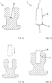
Figure 1 shows in cut-view the supporting part in a first embodiment, -
Figure 2 shows the stud pin in a first embodiment, -
Figure 3 shows in cut-view pressing of the stud pin shown infigure 1 into blind hole of the supporting part shown infigure 2 , -
Figure 4 shows in cut-view an anti-skid stud according to a first embodiment, -
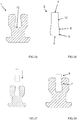
Figure 5 shows in cut-view the supporting part in a second embodiment, -
Figure 6 shows the stud pin in a second embodiment, -
Figure 7 shows in cut-view pressing of the stud pin shown infigure 6 into blind hole of the supporting part shown infigure 5 , -
Figure 8 shows in cut-view an anti-skid stud according to a second embodiment, -
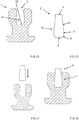
Figure 9 shows in cut-view the supporting part in a third embodiment, -
Figure 10 shows the stud pin in a third embodiment, -
Figure 11 shows in cut-view pressing of the stud pin shown infigure 10 into blind hole of the supporting part shown infigure 9 , -
Figure 12 shows in cut-view an anti-skid stud according to a third embodiment, -
Figure 13 shows in cut-view the supporting part in a fourth embodiment, -
Figure 14 shows the stud pin in a fourth embodiment, -
Figure 15 shows in cut-view pressing of the stud pin shown infigure 14 into blind hole of the supporting part shown infigure 13 , -
Figure 16 shows in cut-view an anti-skid stud according to a first embodiment, -
Figure 17 shows in cut-view the supporting part in a fifth embodiment, -
Figure 18 shows the stud pin in a fifth embodiment, -
Figure 19 shows in cut-view pressing of the stud pin shown infigure 18 into blind hole of the supporting part shown infigure 17 , -
Figure 20 shows in cut-view an anti-skid stud according to a fifth embodiment, -
Figure 21 shows in cut-view the supporting part in a sixth embodiment, -
Figure 22 shows the stud pin in a sixth embodiment, -
Figure 23 shows in cut-view pressing of the stud pin shown infigure 22 into blind hole of the supporting part shown infigure 21 , -
Figure 24 shows in cut-view an anti-skid stud according to a sixth embodiment, -
Figure 25 shows in cut-view the supporting part in a seventh embodiment, -
Figure 26 shows the stud pin in a seventh embodiment, -
Figure 27 shows in cut-view pressing of the stud pin shown infigure 26 into blind hole of the supporting part shown infigure 25 , -
Figure 28 shows in cut-view an anti-skid stud according to a seventh embodiment, -
Figure 29 shows in cut-view the supporting part in an eight embodiment, -
Figure 30 shows the stud pin in an eight embodiment, -
Figure 31 shows in cut-view pressing of the stud pin shown infigure 30 into blind hole of the supporting part shown infigure 29 , -
Figure 32 shows in cut-view an anti-skid stud according to an eight embodiment, -
Figure 33 shows in cut-view the supporting part in a ninth embodiment, -
Figure 34 shows the stud pin in a ninth embodiment, -
Figure 35 shows in cut-view pressing of the stud pin shown infigure 34 into blind hole of the supporting part shown infigure 33 , -
Figure 36 shows in cut-view an anti-skid stud according to a ninth embodiment, -
Figure 37 shows in cut-view the supporting part in a tenth embodiment, -
Figure 38 shows the stud pin in a tenth embodiment, -
Figure 39 shows in cut-view pressing of the stud pin shown infigure 38 into blind hole of the supporting part shown infigure 37 , -
Figure 40 shows in cut-view an anti-skid stud according to a tenth embodiment, -
Figure 41 shows in cut-view the supporting part in an eleventh embodiment, -
Figure 42 shows the stud pin in an eleventh embodiment, -
Figure 43 shows in cut-view pressing of the stud pin shown infigure 42 into blind hole of the supporting part shown infigure 41 , -
Figure 44 shows in cut-view an anti-skid stud according to an eleventh embodiment, -
Figure 45 shows in cut-view the supporting part in a twelfth embodiment, -
Figure 46 shows the stud pin in a twelfth embodiment, -
Figure 47 shows in cut-view pressing of the stud pin shown infigure 46 into blind hole of the supporting part shown infigure 45 , -
Figure 48 shows in cut-view an anti-skid stud according to a twelfth embodiment, -
Figure 49 shows in cut-view the supporting part in a thirteenth embodiment, -
Figure 50 shows the stud pin in a thirteenth embodiment, -
Figure 51 shows in cut-view pressing of the stud pin shown infigure 50 into blind hole of the supporting part shown infigure 49 , -
Figure 52 shows in cut-view an anti-skid stud according to a thirteenth eleventh embodiment. - First the method for producing an anti-skid stud comprising a supporting
part 1 and astud pin 2 that is partly arranged in ablind hole 3 in the supportingpart 1 and some variants and embodiments of the method will be described in greater detail. - The method comprises providing a supporting
part 1 that is made of elastic or of elastically deformable material such as of polymer and that has ablind hole 3. - The elastic or elastically deformable material is essentially homogenous and/or is, free of fibers. An advantage of such material is the capably to deform elastically without breaking.
- The method comprises providing a
stud pin 2 having aproximal end 4 and adistal end 5. Thestud pin 2 can be made of or comprise hard material such as metal, and comprises preferably, but not necessarily, hard metal such as tungsten carbide and/or other carbides. - The
stud pin 2 that is provided comprises a protrudinggrip section 6 and aninsertion section 7 having at least onefirst holding section 16. In the embodiments illustrated infigures 1 to 40 and infigures 45 to 52 , theinsertion section 7 of thestud pin 2 has onefirst holding section 16 and in the eleventh embodiment illustrated infigures 41 to 44 , theinsertion section 7 of thestud pin 2 has twofirst holding sections 16. - The
blind hole 3 of the supportingpart 1 that is provided has a bottom 15 and asecond holding section 17. Thesecond holding section 17 has a smallest cross-section A that is smaller than a largest cross section B of thefirst holding section 16 of theinsertion section 7 of thestud pin 2 that is provided. - The method comprises providing at least one of i) the
insertion section 7 of thestud pin 2 with afirst tapering section 9 that tapers for example in a beveled and/or rounded manner toward thedistal end 5 of thestud pin 2, and ii) amouth 18 of theblind hole 3 of the supportingpart 1 with a beveled and/or rounded edge. In the embodiment illustrated infigures 1 to 4 , afirst tapering section 9 is provided, but themouth 18 of theblind hole 3 is not provided with a beveled and/or rounded edge. In the embodiment illustrated infigures 13 to 18 , no first tapering section is provided, but themouth 18 of theblind hole 3 is provided with abeveled edge 3. In the other embodiments, afirst tapering section 9 is provided, and themouth 18 of theblind hole 3 is provided with a beveled and/or rounded edge - The method comprises pressing the
insertion section 7 of thestud pin 2 into theblind hole 3 of the supportingpart 1 with thedistal end 5 of thestud pin 2 leading theinsertion section 7 of thestud pin 2 so that said largest cross section B of thefirst holding section 16 of thestud pin 2 at least partly passes said smallest cross-section A of thesecond holding section 17 of theblind hole 3 of the supportingpart 1. Because the supportingpart 1 is made of elastic or elastically deformable material, the largest cross section B of thefirst holding section 16 of thestud pin 2 can at least partly pass the smallest cross-section A of thesecond holding section 17 of theblind hole 3 of the supportingpart 1. - A purpose of the
first holding section 16 of thestud pin 2 and of thesecond holding section 17 of theblind hole 3 of the supportingpart 1 to retain thestud pin 2 in theblind hole 3 of the supportingpart 1. - A purpose of the
first tapering section 9 of theinsertion section 7 of thestud pin 2 and/or of the beveled or rounded edge of themouth 18 of theblind hole 3 of the supportingpart 1 is to enable pressing of thestud pin 2 into theblind hole 3 of the supportingpart 1. - The
insertion section 7 of thestud pin 2 can be provided with afirst holding section 16 in the form of a first enlargement (nor marked with a reference numeral), as is the case in the embodiments shown in the figures and theblind hole 3 of the supportingpart 1 can be provided with asecond holding section 17 in the form of a second enlargement (nor marked with a reference numeral), as is the case in the first to ninth embodiment illustrated infigures 1 to 36 and in the thirteenth embodiment illustrated infigures 49 to 52 . In such cases, pressing of theinsertion section 7 of thestud pin 2 into theblind hole 2 of the supportingpart 1 causes the largest cross section B of thefirst holding section 16 of thestud pin 2 to pass the smallest cross-section A of thesecond holding section 17 of theblind hole 3 of the supportingpart 1. - Alternatively, the
insertion section 7 of thestud pin 2 can be provided with afirst holding section 16 in the form of a first enlargement (nor marked with a reference numeral), as is the case in the embodiments shown in the figures and the cross-section of theblind hole 3 of the supportingpart 1 can be essentially the same throughout theblind hole 3 of the supportingpart 1, as is the case in the tenth to twelfth embodiment illustrated infigures 37 to 48 . In such cases, pressing of theinsertion section 7 of thestud pin 2 into theblind hole 2 of the supportingpart 1 causes the largest cross section B of thefirst holding section 16 of thestud pin 2 to only partly pass the smallest cross-section A of thesecond holding section 17 of theblind hole 3 of the supportingpart 1. Because the supportingpart 1 is made of elastic or elastically deformable material, thefirst holding section 16 of theinsertion section 7 of thestud pin 2 will cause an enlargement in theblind hole 3 of the supportingpart 1. - The
first holding section 16 of theinsertion section 7 of thestud pin 2 that is provided can have asecond tapering section 8 that tapers towards theproximal end 4 of thestud pin 2, as is the case in the embodiments illustrated infigures 1 to 32 and infigures 45 to 52 . - The
insertion section 7 of thestud pin 2 that is provided is between thefirst holding section 16 and the protrudinggrip section 6 comprise atop section 12, which cross section is essentially the same throughout the top section as illustrated in the embodiments illustrated infigures 33 to 40 . - The form and the dimensions of at least a part of the
blind hole 3 of the supportingpart 1 that is provided corresponds preferably, but not necessarily, essentially to the form and to the dimensions of at least a part of theinsertion section 7 of thestud pin 2. This provides for a tight fit between theinsertion section 7 of thestud pin 2 and theblind hole 3 of the supportingpart 1, which extends the service-life of the anti-skid stud, because thestud pin 2 is well-retained in the supportingpart 1. - The method can comprise pressing the
insertion section 7 of thestud pin 2 into theblind hole 3 of the supportingpart 1 with thedistal end 5 leading thestud pin 2 until thedistal end 5 of thestud pin 2 abuts the bottom 15 of theblind hole 3 and until the protrudinggrip section 6 of thestud pin 2 is located outside theblind hole 3, as in the embodiments illustrated infigures 1 to 48 . An advantage of this is that thestud pin 2 is then prevented from sinking deeper into theblind hole 3 of the supportingpart 1. - Alternatively, the method can comprise pressing the
insertion section 7 of thestud pin 2 into theblind hole 3 of the supportingpart 1 with thedistal end 5 leading thestud pin 2 until thedistal end 5 of thestud pin 2 is at a distance from the bottom 15 of theblind hole 3 and until the protrudinggrip section 6 of thestud pin 2 is located outside theblind hole 3, as in the thirteenth embodiment illustrated infigures 49 to 52 . In such case thefirst holding section 16 of theinsertion section 7 of thestud pin 2 can together with thesecond holding section 17 of theblind hole 3 of the supportingpart 1 be configured to prevent thestud pin 2 from sinking deeper into theblind hole 3 of the supportingpart 1. An advantage of this embodiment is that the length of thestud pin 2 has then a smaller impact on the length of the protrudinggrip section 6 of thestud pin 2. - In the method, the
second section 9 of theinsertion section 7 can extend directly from thedistal end 5 in thestud pin 2 that is provided, as in the embodiments shown infigures 1 to 48 . - In the method, the
stud pin 2 that is provided can comprise a leadingsection 10 between thefirst tapering section 9 of thefirst holding section 16 of theinsertion section 7 of thestud pin 2 and thedistal end 5 of thestud pin 2, provided that thestud pin 2 is provided with suchfirst tapering section 9, as in the thirteenth embodiment shown infigures 49 to 52 . - In the method, the
stud pin 2 that is provided can comprise amiddle section 11 between thefirst tapering section 9 of thefirst holding section 16 of theinsertion section 7 and thesecond tapering section 8 of thefirst holding section 16 of theinsertion section 7, provided that thestud pin 2 comprises suchfirst tapering section 9 and suchsecond tapering section 8, as in the eight embodiment shown infigures 29 to 32 . - In the method, the
stud pin 2 that is provided can comprise atop section 12 between thesecond tapering section 8 of theinsertion section 7 and the protrudinggrip section 6, provided that thestud pin 2 comprises suchsecond tapering section 8, as in the seventh embodiment shown in figured 25 to 28. - In the method, the
second tapering section 8 of theinsertion section 7 can extend directly from the protrudinggrip section 6 of thestud pin 2 that is provided, provided that thestud pin 2 comprises suchsecond tapering section 8, as in the embodiments shown infigures 1 to 24 ,. - The optional
second tapering section 8 of thefirst holding section 16 of theinsertion section 7 of thestud pin 2 can be in the form of a first truncated cone, and the optionalfirst tapering section 9 of thefirst holding section 16 of theinsertion section 7 of thestud pin 2 can be in the form of a second truncated cone. - The
insertion section 7 of thestud pin 2 that is provided can have a form enabling inserting thestud pin 2 only in one position into theblind hole 3 of the supportingpart 1. - The method can comprise providing the
second holding section 17 of theblind hole 3 of the supportingpart 1 with an undercut recess (not marked with a reference numeral), wherein thefirst holding section 16 of theinsertion section 7 of thestud pin 2 is configured to latch into the undercut recess of thesecond holding section 17 of theblind hole 3 of the supportingpart 1 when pressing theinsertion section 7 of thestud pin 2 into theblind hole 3 of the supportingpart 1. An advantage of this is that is then easy to press thestud pin 2 into a correct positionblind hole 3 in the supportingpart 1. - The method can comprise providing the supporting
part 1 with atop flange 13 and with abottom flange 14. This enhances keeping of the anti-skid stud in a tire, when the anti-skid stud is mounted in a recess in a tire. - The supporting body can comprise a ridge or a tooth or a spline on the outer surface of the supporting body. Additionally or alternatively, the supporting
part 1 can have an outer form diverging from the form of a solid of revolution An advantage of this is that the anti-skid stud is prevented from rotating a recess of the tire when mounted in a recess in a tire and the anti-skid stud is kept in a predetermined rotational position with respect to the tire. This also allows to insert the anti-skid stud into a recess in a tire with a machine in a predetermined position and promotes also retaining of the anti-skid stud in a tire. - The method can comprise heating at least one of the supporting
part 1 and thestud pin 2 prior pressing theinsertion section 7 of thestud pin 2 into theblind hole 3 of the supportingpart 1. An advantage of this is that it is then easier to press thestud pin 2 into theblind hole 3, because the supportingpart 1 softens and can better yield during the pressing. - Next the anti-skid stud comprising a supporting
part 1 and astud pin 2 that is partly arranged in ablind hole 3 in the supportingpart 1 and some variants and embodiments of the anti-skid stud will be described in greater detail. - The anti-skid stud comprises a supporting
part 1 that is made of elastic or of elastically deformable material such as of polymer and that has ablind hole 3, and astud pin 2 having aproximal end 4 and adistal end 5. Thestud pin 2 can be made of or comprise hard material such as metal, and comprises preferably, but not necessarily, hard metal such as tungsten carbide and/or other carbides. - The elastic or elastically deformable material the supporting
part 1 isessentially homogenous and/or free of fibers. An advantage of such material is the capably to deform elastically without breaking. - The
stud pin 2 comprises a protrudinggrip section 6 and aninsertion section 7 having at least onefirst holding section 16. In the embodiments illustrated infigures 1 to 40 and infigures 45 to 52 , theinsertion section 7 of thestud pin 2 has onefirst holding section 16 and in the eleventh embodiment illustrated infigures 41 to 44 , theinsertion section 7 of thestud pin 2 has twofirst holding sections 16. - The
blind hole 3 of the supportingpart 1 has a bottom 15 and asecond holding section 17 having a smallest cross-section A that is smaller than a largest cross section B of thefirst holding section 16 of theinsertion section 7 of thestud pin 2. - At least one of the
insertion section 7 of thestud pin 2 is provided with afirst tapering section 9 that tapers for example in a beveled and/or rounded manner toward thedistal end 5 of thestud pin 2 and amouth 18 of theblind hole 3 of the supportingpart 1 is provided with a beveled and/or rounded edge. In the embodiment illustrated infigures 1 to 4 , afirst tapering section 9 is provided, but themouth 18 of theblind hole 3 is not provided with a beveled and/or rounded edge. In the embodiment illustrated infigures 13 to 18 , no first tapering section is provided, but themouth 18 of theblind hole 3 is provided with abeveled edge 3. In the other embodiments, afirst tapering section 9 is provided, and themouth 18 of theblind hole 3 is provided with a beveled and/or rounded edge - Said
insertion section 7 of thestud pin 2 is retained in theblind hole 3 of the supportingpart 1 by a form-fit and/or press-fit connection between theinsertion section 7 of thestud pin 2 and theblind hole 3 of the supportingpart 1. A form-fit and press-fit connection is achieved by providing theblind hole 3 of the supportingpart 1 and theinsertion section 7 of thestud pin 2 with an at least partly matching design and by making the dimensions of theblind hole 3 of the supportingpart 1 smaller than the dimensions of theinsertion section 16 of the stud pin. - Said largest cross section B of the
first holding section 16 of theinsertion section 7 of thestud pin 2 is arranged between the bottom 15 of theblind hole 3 of the supportingpart 1 and said smallest cross-section A of thesecond holding section 17 of theblind hole 3 of the supportingpart 1. - A purpose of the
first holding section 16 of thestud pin 2 and of thesecond holding section 17 of theblind hole 3 of the supportingpart 1 to retain thestud pin 2 in theblind hole 3 of the supportingpart 1. - A purpose of the
first section 9 of theinsertion section 7 of thestud pin 2 or of the beveled or rounded edge of themouth 18 of theblind hole 3 of the supportingpart 1 is to enable pressing of thestud pin 2 into theblind hole 3 of the supportingpart 1, when manufacturing the anti-skid stud. - The
insertion section 7 of thestud pin 2 can be provided with afirst holding section 16 in the form of a first enlargement (nor marked with a reference numeral), as is the case in the embodiments shown in the figures and theblind hole 3 of the supportingpart 1 can be provided with asecond holding section 17 in the form of a second enlargement (nor marked with a reference numeral), as is the case in the first to ninth embodiment illustrated infigures 1 to 36 and in the thirteenth embodiment illustrated infigures 49 to 52 . In such cases, the largest cross section B of thefirst holding section 16 of thestud pin 2 is between the smallest cross-section A of thesecond holding section 17 of theblind hole 3 of the supportingpart 1 and the bottom 15 of theblind hole 3 of the supportingpart 1 in the anti-skid stud. - Alternatively, the
insertion section 7 of thestud pin 2 can be provided with afirst holding section 16 in the form of a first enlargement (nor marked with a reference numeral), as is the case in the embodiments shown in the figures and the cross-section of theblind hole 3 of the supportingpart 1 can be essentially the same throughout theblind hole 3 of the supportingpart 1, as is the case in the tenth to twelfth embodiment illustrated infigures 37 to 48 . In such cases, the largest cross section B of thefirst holding section 16 of thestud pin 2 can be considered to be at the smallest cross-section A of thesecond holding section 17 of theblind hole 3 of the supportingpart 1. Because the supportingpart 1 is made of elastic or elastically deformable material, thefirst holding section 16 of theinsertion section 7 of thestud pin 2 will however cause an enlargement in theblind hole 3 of the supportingpart 1. - The
first holding section 16 of theinsertion section 7 of thestud pin 2 can have asecond tapering section 8 that tapers towards theproximal end 4 of thestud pin 2, as in the embodiments illustrated infigures 1 to 32 and infigures 45 to 52 . - According to the invention, the
insertion section 7 of thestud pin 2 comprise between thefirst holding section 16 and the protruding grip section 6 atop section 12, which cross section is essentially the same throughout the top section as illustrated in the embodiments illustrated infigures 33 to 40 .The form and the dimensions of at least a part of theblind hole 3 of the supportingpart 1 corresponding preferably, but not necessarily, essentially to the form and to the dimensions of at least a part of theinsertion section 7 of thestud pin 2. - The
distal end 5 of thestud pin 2 can abut the bottom 15 of theblind hole 3 of the supportingpart 1 so that the protrudinggrip section 6 of thestud pin 2 is located outside theblind hole 3 of the supportingpart 1, as in the embodiments illustrated infigures 1 to 48 . - Alternatively, the
distal end 5 of thestud pin 2 can be located at a distance from the bottom 15 of theblind hole 3 of the supportingpart 1 so that the protrudinggrip section 6 of thestud pin 2 is located outside theblind hole 3 of the supportingpart 1, as in the embodiment illustrated infigures 49 to 52 . - The
stud pin 2 can comprise a leadingsection 10 between thefirst tapering section 9 of thefirst holding section 16 of theinsertion section 7 of thestud pin 2 and thedistal end 5 of thestud pin 2, provided that thestud pin 2 is provided with suchfirst tapering section 9, as in the thirteenth embodiment shown infigures 49 to 52 . - The
stud pin 2 can comprise amiddle section 11 between thefirst tapering section 9 of thefirst holding section 16 of theinsertion section 7 and thesecond tapering section 8 of thefirst holding section 16 of theinsertion section 7, provided that thestud pin 2 comprises suchfirst tapering section 9 and suchsecond tapering section 8, as in the eight embodiment shown infigures 29 to 32 . - The
stud pin 2 can comprise atop section 12 between thesecond tapering section 8 of theinsertion section 7 and the protrudinggrip section 6, provided that thestud pin 2 comprises suchsecond tapering section 8, as in the seventh embodiment shown in figured 25 to 28. - The
second tapering section 8 of theinsertion section 7 can extend directly from the protrudinggrip section 6 of thestud pin 2 that is provided, provided that thestud pin 2 comprises suchsecond tapering section 8, as in the embodiments shown infigures 1 to 24 and29 to 32 and45 to 52 . - The optional
second tapering section 8 of thefirst holding section 16 of theinsertion section 7 of thestud pin 2 can be in the form of a first truncated cone, and the optionalfirst tapering section 9 of thefirst holding section 16 of theinsertion section 7 of thestud pin 2 can be in the form of a second truncated cone. - The
insertion section 7 of thestud pin 2 can have a form diverging from the form of a solid of revolution, and the protrudinggrip section 6 of thestud pin 2 can have a form diverging from the form of a solid of revolution. An advantage of this is that thestud pin 2 is prevented from rotating in theblind hole 3 and thestud pin 2 is kept in a predetermined rotational position with respect to theblind hole 3. - Alternatively, the
insertion section 7 of thestud pin 2 can have the form of a solid of revolution, and the protrudinggrip section 6 of thestud pin 2 can have the form of a solid of revolution. - The
blind hole 3 of the supportingpart 1 can be provided with an undercut recess, and thefirst holding section 16 of theinsertion section 7 of thestud pin 2 can be latched into the undercut recess in theblind hole 3 of the supportingpart 1. An advantage of this is that is then easy to press thestud pin 2 into a correct positionblind hole 3 in the supportingpart 1. - The supporting
part 1 can be provided with atop flange 13 and with abottom flange 14. This enhances keeping of the anti-skid stud in a tire, then the anti-skid stud is mounted in a recess in a tire. - The supporting body can comprise a ridge or a tooth or a spline on the outer surface of the supporting body. Additionally or alternatively, the supporting
part 1 can have an outer form diverging from the form of a solid of revolution An advantage of this is that the anti-skid stud is prevented from rotating a recess of the tire when mounted in a recess in a tire and the anti-skid stud is kept in a predetermined rotational position with respect to the tire. - It is apparent to a person skilled in the art that as technology advanced, the basic idea of the invention can be implemented in various ways. The invention and its embodiments are therefore not restricted to the above examples, but they may vary within the scope of the appended claims.
Claims (20)
- A method for producing an anti-skid stud comprising a supporting part (1) and a stud pin (2) that is partly arranged in a blind hole (3) in the supporting part (1), wherein method comprises
providing a supporting part (1) that is made of elastic material, which is essentially homogenous and/or is free of fibers, such as of polymer and that has a blind hole (3), and
providing a stud pin (2) having a proximal end (4) and a distal end (5), the stud pin (2) is provided comprising a protruding grip section (6) and an insertion section (7) having a first holding section (16),
the blind hole (3) of the supporting part (1) is provided having a bottom (15) and a second holding section (17) having a smallest cross-section A that is smaller than a largest cross section B of the first holding section (16) of the insertion section of the stud pin (2) that is provided the method is characterized
by providing at least one of i) the insertion section (7) of the stud pin (2) with a first tapering section (9) that tapers toward the distal end (5) of the stud pin (2), and ii) a mouth (18) of the blind hole (3) of the supporting part (1) with a beveled and/or rounded edge,
by pressing the insertion section (7) of the stud pin (2) into the blind hole (3) of the supporting part (1) with the distal end (5) leading the insertion section (7) of the stud pin (2) so that said largest cross section B of the first holding section (16) of the stud pin (2) at least partly passes said smallest cross-section A of the second holding section (17) of the blind hole (3) of the supporting part (1),
by the first holding section (16) of the stud pin (2) that is provided is located at the distal end (5) of the stud pin (2), and
by the inserting section (7) of the stud pin (2) that is provided has between the first holding section (16) of the stud pin and the protruding grip section (6) of the stud pin (2) a top section (12) which cross section which is essentially the same throughout the top section (12). - The method according to claim 1, characterized
by the first holding section (16) of the insertion section (7) of the stud pin (2) that is provided having a second tapering section (8) that tapers towards the proximal end (4) of the stud pin (2). - The method according to claim 1 or 2, characterized
by the form and the dimensions of at least a part of the blind hole (3) of the supporting part (1) that is provided corresponding essentially to the form and to the dimensions of at least a part of the insertion section (7) of the stud pin (2). - The method according to any of the claims 1 to 3, characterized
by pressing the insertion section (7) of the stud pin (2) into the blind hole (3) of the supporting part (1) with the distal end (5) leading the stud pin (2) until the distal end (5) of the stud pin (2) abuts the bottom (15) of the blind hole (3) and until the protruding grip section (6) of the stud pin (2) is located outside the blind hole (3). - The method according to any of the claims 1 to 3, characterized
by pressing the insertion section (7) of the stud pin (2) into the blind hole (3) of the supporting part (1) with the distal end (5) leading the stud pin (2) until the distal end (5) of the stud pin (2) is at a distance from the bottom (15) of the blind hole (3) and until the protruding grip section (6) of the stud pin (2) is located outside the blind hole (3). - The method according to any of the claims 1 to 5, characterized
by the insertion section (7) of the stud pin (2) that is provided having a form diverging from the form of a solid of revolution, and
by the protruding grip section (6) of the stud pin (2) that is provided having a form diverging from the form of a solid of revolution. - The method according to any of the claims 1 to 6, characterized
by the insertion section (7) of the stud pin (2) that is provided having a form enabling inserting the stud pin (2) only in one position into the blind hole (3) of the supporting part (1). - The method according to any of the claims 1 to 7, characterized
by providing the blind hole (3) of the supporting part (1) with an undercut recess, and
by the first holding section (16) of the insertion section (7) of the stud pin (2) being configured to latch into the undercut recess when pressing the insertion section (7) of the stud pin (2) into the blind hole (3) of the supporting part (1). - The method according to any of the claims 1 to 8, characterized
by providing the supporting part (1) with a top flange (13) and with a bottom flange (14). - The method according to any of the claims 1 to 9, characterized
by heating at least one of the supporting part (1) and the stud pin (2) prior pressing the insertion section (7) of the stud pin (2) into the blind hole (3) of the supporting part (1). - The method according to any of the claims 1 to 10, characterized
by said elastic material being elastically deformable material. - An anti-skid stud comprising a supporting part (1) and a stud pin (2) that is partly arranged in a blind hole (3) in the supporting part (1), wherein the anti-skid stud comprises
a supporting part (1) that is made of elastic material, which is essentially homogenous and/or free of fibers, such as of polymer and that has a blind hole (3), and
a stud pin (2) having a proximal end (4) and a distal end (5)
wherein
the stud pin (2) comprising a protruding grip section (6) and an insertion section (7) having a first holding section (16),
the blind hole (3) of the supporting part (1) having a second holding section (17) having a smallest cross-section A that is smaller than a largest cross-section B of the first holding section (16) of the insertion section (7) of the stud pin (2; said largest cross-section B of the first holding section (16) of the insertion section (7) of the stud pin (2) is between a bottom (15) of the blind hole (3) of the supporting part (1) and said smallest cross-section A of the second holding section (17) of the blind hole (3) of the supporting part (1),
the anti-skid stub being characterized by at least one of i) the insertion section (7) of the stud pin (2) being provided with a first tapering section (9) that tapers toward the distal end (5) of the stud pin (2), and ii) a mouth (18) of the blind hole (3) of the supporting part (1) being provided with a beveled and/or rounded edge,
by said insertion section (7) of the stud pin (2) being retained in the blind hole (3) of the supporting part (1) by a form-fit and/or press-fit connection between the insertion section (7) of the stud pin (2) and the blind hole (3) of the supporting part (1),
by the first holding section (16) of the stud pin (2) is provided at the distal end (5) of the stud pin (2), and
by the inserting section (7) of the stud pin (2) has between the first holding section (16) of the stud pin and the protruding grip section (6) of the stud pin (2) a top section (12) which cross section which is essentially the same throughout the top section (12). - The anti-skid stud according to claim 12, characterized
by the first holding section (16) of the insertion section (7) of the stud pin (2) having a second tapering section (8) that tapers towards the proximal end (4) of the stud pin (2). - The anti-skid stud according to claim 12 or 13, characterized
by the form and the dimensions of at least a part of the blind hole (3) of the supporting part (1) corresponding essentially to the form and to the dimensions of at least a part of the insertion section (7) of the stud pin (2). - The anti-skid stud according to any of the claims 12 to 14, characterized
by the distal end (5) of the stud pin (2) abuts the bottom (15) of the blind hole (3) of the supporting part (1) and by the protruding grip section (6) of the stud pin (2) is located outside the blind hole (3) of the supporting part (1). - The anti-skid stud according to any of the claims 12 to 14, characterized
by the distal end (5) of the stud pin (2) being located at a distance from the bottom (15) of the blind hole (3) of the supporting part (1) and by the protruding grip section (6) of the stud pin (2) being located outside the blind hole (3) of the supporting part (1). - The anti-skid stud according to any of the claims 12 to 16, characterized
by the insertion section (7) of the stud pin (2) having a form diverging from the form of a solid of revolution, and
by the protruding grip section (6) of the stud pin (2) having a form diverging from the form of a solid of revolution. - The anti-skid stud according to any of the claims 12 to 17, characterized
by the second holding section (17) of the blind hole (3) of the supporting part (1) being provided with an undercut recess, and
by the first holding section (16) of the insertion section (7) of the stud pin (2) being latched into the undercut recess in the blind hole (3) of the supporting part (1). - The anti-skid stud according to any of the claims 12 to 18, characterized
by the supporting body being provided with a top flange (13) and with a bottom flange (14). - The anti-skid stud according to any of the claims 12 to 19, characterized
by said elastic material being elastically deformable material.
Applications Claiming Priority (1)
| Application Number | Priority Date | Filing Date | Title |
|---|---|---|---|
| FI20185176A FI128455B (en) | 2018-02-26 | 2018-02-26 | Method for producing an anti-skid stud and anti-skid stud |
Publications (2)
| Publication Number | Publication Date |
|---|---|
| EP3530490A1 EP3530490A1 (en) | 2019-08-28 |
| EP3530490B1 true EP3530490B1 (en) | 2021-04-28 |
Family
ID=65598464
Family Applications (1)
| Application Number | Title | Priority Date | Filing Date |
|---|---|---|---|
| EP19159272.4A Active EP3530490B1 (en) | 2018-02-26 | 2019-02-26 | Method for producing an anti-skid stud and anti-skid stud |
Country Status (2)
| Country | Link |
|---|---|
| EP (1) | EP3530490B1 (en) |
| FI (1) | FI128455B (en) |
Family Cites Families (2)
| Publication number | Priority date | Publication date | Assignee | Title |
|---|---|---|---|---|
| GB1063936A (en) * | 1965-10-29 | 1967-04-05 | Kennametal Inc | Tire stud |
| RU2148498C1 (en) * | 1998-03-30 | 2000-05-10 | ОАО"Нижнекамскшина" | Anti-skid stud for vehicle tyres |
-
2018
- 2018-02-26 FI FI20185176A patent/FI128455B/en active IP Right Grant
-
2019
- 2019-02-26 EP EP19159272.4A patent/EP3530490B1/en active Active
Non-Patent Citations (1)
| Title |
|---|
| None * |
Also Published As
| Publication number | Publication date |
|---|---|
| EP3530490A1 (en) | 2019-08-28 |
| FI20185176A1 (en) | 2019-08-27 |
| FI128455B (en) | 2020-05-29 |
Similar Documents
| Publication | Publication Date | Title |
|---|---|---|
| CN101566185B (en) | Clip | |
| ES2930197T3 (en) | Excavator Wear Kit | |
| US20130304136A1 (en) | Frangible fixing screw | |
| CN105682822B (en) | Rivet element | |
| US20080167652A1 (en) | Tool for making drill-holes in bones or removing cylindrical drill-hole cores from bones of the human body | |
| CN107106267A (en) | Monodentate implant in bone | |
| EP1018781A3 (en) | Feed horn having elliptic open end | |
| EP3530490B1 (en) | Method for producing an anti-skid stud and anti-skid stud | |
| DE102018111383A1 (en) | Valve diaphragm, diaphragm valve, and method for securing a data carrier received in a housing | |
| JP2014514512A (en) | Conduit connector for plastic conduit with connecting plug | |
| US6223384B1 (en) | Trowel with a handle | |
| CN103429195A (en) | Apparatus for replacing a damaged spinal disc | |
| DE19910277B4 (en) | Spinning rotor for open-end spinning machines | |
| CN209324821U (en) | End anchoring piece | |
| US10493716B2 (en) | Heat stake and method of eliminating heat stake sink marks in a plastic part | |
| MX2011003406A (en) | Writing implement comprising a slide-on end member. | |
| EP1798069A2 (en) | Stud for studded tyre | |
| JP3137779U (en) | Tine device for aeration machine | |
| US20110308350A1 (en) | Rotor/Shaft Pin Coupling Assembly for Pedal Assembly | |
| JP2009180030A (en) | Excavation tool | |
| CN102835996B (en) | Lockpin type central nail device | |
| EP1231041A1 (en) | An injector nozzle for moulding plastics materials | |
| KR102318474B1 (en) | Felt needles and methods of making at least one felt needle | |
| CN210423338U (en) | Round pin installation guide structure | |
| CN215481674U (en) | Rotating hook and sewing machine |
Legal Events
| Date | Code | Title | Description |
|---|---|---|---|
| PUAI | Public reference made under article 153(3) epc to a published international application that has entered the european phase |
Free format text: ORIGINAL CODE: 0009012 |
|
| STAA | Information on the status of an ep patent application or granted ep patent |
Free format text: STATUS: THE APPLICATION HAS BEEN PUBLISHED |
|
| AK | Designated contracting states |
Kind code of ref document: A1 Designated state(s): AL AT BE BG CH CY CZ DE DK EE ES FI FR GB GR HR HU IE IS IT LI LT LU LV MC MK MT NL NO PL PT RO RS SE SI SK SM TR |
|
| AX | Request for extension of the european patent |
Extension state: BA ME |
|
| STAA | Information on the status of an ep patent application or granted ep patent |
Free format text: STATUS: REQUEST FOR EXAMINATION WAS MADE |
|
| 17P | Request for examination filed |
Effective date: 20200129 |
|
| RBV | Designated contracting states (corrected) |
Designated state(s): AL AT BE BG CH CY CZ DE DK EE ES FI FR GB GR HR HU IE IS IT LI LT LU LV MC MK MT NL NO PL PT RO RS SE SI SK SM TR |
|
| STAA | Information on the status of an ep patent application or granted ep patent |
Free format text: STATUS: EXAMINATION IS IN PROGRESS |
|
| 17Q | First examination report despatched |
Effective date: 20200626 |
|
| GRAP | Despatch of communication of intention to grant a patent |
Free format text: ORIGINAL CODE: EPIDOSNIGR1 |
|
| STAA | Information on the status of an ep patent application or granted ep patent |
Free format text: STATUS: GRANT OF PATENT IS INTENDED |
|
| INTG | Intention to grant announced |
Effective date: 20201209 |
|
| GRAS | Grant fee paid |
Free format text: ORIGINAL CODE: EPIDOSNIGR3 |
|
| GRAA | (expected) grant |
Free format text: ORIGINAL CODE: 0009210 |
|
| STAA | Information on the status of an ep patent application or granted ep patent |
Free format text: STATUS: THE PATENT HAS BEEN GRANTED |
|
| AK | Designated contracting states |
Kind code of ref document: B1 Designated state(s): AL AT BE BG CH CY CZ DE DK EE ES FI FR GB GR HR HU IE IS IT LI LT LU LV MC MK MT NL NO PL PT RO RS SE SI SK SM TR |
|
| REG | Reference to a national code |
Ref country code: GB Ref legal event code: FG4D |
|
| REG | Reference to a national code |
Ref country code: CH Ref legal event code: EP |
|
| REG | Reference to a national code |
Ref country code: AT Ref legal event code: REF Ref document number: 1386672 Country of ref document: AT Kind code of ref document: T Effective date: 20210515 |
|
| REG | Reference to a national code |
Ref country code: DE Ref legal event code: R096 Ref document number: 602019004119 Country of ref document: DE |
|
| REG | Reference to a national code |
Ref country code: IE Ref legal event code: FG4D |
|
| REG | Reference to a national code |
Ref country code: SE Ref legal event code: TRGR |
|
| REG | Reference to a national code |
Ref country code: LT Ref legal event code: MG9D |
|
| REG | Reference to a national code |
Ref country code: NO Ref legal event code: T2 Effective date: 20210428 |
|
| REG | Reference to a national code |
Ref country code: AT Ref legal event code: MK05 Ref document number: 1386672 Country of ref document: AT Kind code of ref document: T Effective date: 20210428 |
|
| PG25 | Lapsed in a contracting state [announced via postgrant information from national office to epo] |
Ref country code: NL Free format text: LAPSE BECAUSE OF FAILURE TO SUBMIT A TRANSLATION OF THE DESCRIPTION OR TO PAY THE FEE WITHIN THE PRESCRIBED TIME-LIMIT Effective date: 20210428 Ref country code: AT Free format text: LAPSE BECAUSE OF FAILURE TO SUBMIT A TRANSLATION OF THE DESCRIPTION OR TO PAY THE FEE WITHIN THE PRESCRIBED TIME-LIMIT Effective date: 20210428 Ref country code: BG Free format text: LAPSE BECAUSE OF FAILURE TO SUBMIT A TRANSLATION OF THE DESCRIPTION OR TO PAY THE FEE WITHIN THE PRESCRIBED TIME-LIMIT Effective date: 20210728 Ref country code: FI Free format text: LAPSE BECAUSE OF FAILURE TO SUBMIT A TRANSLATION OF THE DESCRIPTION OR TO PAY THE FEE WITHIN THE PRESCRIBED TIME-LIMIT Effective date: 20210428 Ref country code: LT Free format text: LAPSE BECAUSE OF FAILURE TO SUBMIT A TRANSLATION OF THE DESCRIPTION OR TO PAY THE FEE WITHIN THE PRESCRIBED TIME-LIMIT Effective date: 20210428 Ref country code: HR Free format text: LAPSE BECAUSE OF FAILURE TO SUBMIT A TRANSLATION OF THE DESCRIPTION OR TO PAY THE FEE WITHIN THE PRESCRIBED TIME-LIMIT Effective date: 20210428 |
|
| PG25 | Lapsed in a contracting state [announced via postgrant information from national office to epo] |
Ref country code: PL Free format text: LAPSE BECAUSE OF FAILURE TO SUBMIT A TRANSLATION OF THE DESCRIPTION OR TO PAY THE FEE WITHIN THE PRESCRIBED TIME-LIMIT Effective date: 20210428 Ref country code: LV Free format text: LAPSE BECAUSE OF FAILURE TO SUBMIT A TRANSLATION OF THE DESCRIPTION OR TO PAY THE FEE WITHIN THE PRESCRIBED TIME-LIMIT Effective date: 20210428 Ref country code: RS Free format text: LAPSE BECAUSE OF FAILURE TO SUBMIT A TRANSLATION OF THE DESCRIPTION OR TO PAY THE FEE WITHIN THE PRESCRIBED TIME-LIMIT Effective date: 20210428 Ref country code: PT Free format text: LAPSE BECAUSE OF FAILURE TO SUBMIT A TRANSLATION OF THE DESCRIPTION OR TO PAY THE FEE WITHIN THE PRESCRIBED TIME-LIMIT Effective date: 20210830 Ref country code: GR Free format text: LAPSE BECAUSE OF FAILURE TO SUBMIT A TRANSLATION OF THE DESCRIPTION OR TO PAY THE FEE WITHIN THE PRESCRIBED TIME-LIMIT Effective date: 20210729 Ref country code: IS Free format text: LAPSE BECAUSE OF FAILURE TO SUBMIT A TRANSLATION OF THE DESCRIPTION OR TO PAY THE FEE WITHIN THE PRESCRIBED TIME-LIMIT Effective date: 20210828 |
|
| REG | Reference to a national code |
Ref country code: NL Ref legal event code: MP Effective date: 20210428 |
|
| PG25 | Lapsed in a contracting state [announced via postgrant information from national office to epo] |
Ref country code: SK Free format text: LAPSE BECAUSE OF FAILURE TO SUBMIT A TRANSLATION OF THE DESCRIPTION OR TO PAY THE FEE WITHIN THE PRESCRIBED TIME-LIMIT Effective date: 20210428 Ref country code: ES Free format text: LAPSE BECAUSE OF FAILURE TO SUBMIT A TRANSLATION OF THE DESCRIPTION OR TO PAY THE FEE WITHIN THE PRESCRIBED TIME-LIMIT Effective date: 20210428 Ref country code: EE Free format text: LAPSE BECAUSE OF FAILURE TO SUBMIT A TRANSLATION OF THE DESCRIPTION OR TO PAY THE FEE WITHIN THE PRESCRIBED TIME-LIMIT Effective date: 20210428 Ref country code: DK Free format text: LAPSE BECAUSE OF FAILURE TO SUBMIT A TRANSLATION OF THE DESCRIPTION OR TO PAY THE FEE WITHIN THE PRESCRIBED TIME-LIMIT Effective date: 20210428 Ref country code: CZ Free format text: LAPSE BECAUSE OF FAILURE TO SUBMIT A TRANSLATION OF THE DESCRIPTION OR TO PAY THE FEE WITHIN THE PRESCRIBED TIME-LIMIT Effective date: 20210428 Ref country code: RO Free format text: LAPSE BECAUSE OF FAILURE TO SUBMIT A TRANSLATION OF THE DESCRIPTION OR TO PAY THE FEE WITHIN THE PRESCRIBED TIME-LIMIT Effective date: 20210428 Ref country code: SM Free format text: LAPSE BECAUSE OF FAILURE TO SUBMIT A TRANSLATION OF THE DESCRIPTION OR TO PAY THE FEE WITHIN THE PRESCRIBED TIME-LIMIT Effective date: 20210428 |
|
| REG | Reference to a national code |
Ref country code: DE Ref legal event code: R097 Ref document number: 602019004119 Country of ref document: DE |
|
| PLBE | No opposition filed within time limit |
Free format text: ORIGINAL CODE: 0009261 |
|
| STAA | Information on the status of an ep patent application or granted ep patent |
Free format text: STATUS: NO OPPOSITION FILED WITHIN TIME LIMIT |
|
| 26N | No opposition filed |
Effective date: 20220131 |
|
| PG25 | Lapsed in a contracting state [announced via postgrant information from national office to epo] |
Ref country code: IS Free format text: LAPSE BECAUSE OF FAILURE TO SUBMIT A TRANSLATION OF THE DESCRIPTION OR TO PAY THE FEE WITHIN THE PRESCRIBED TIME-LIMIT Effective date: 20210828 Ref country code: AL Free format text: LAPSE BECAUSE OF FAILURE TO SUBMIT A TRANSLATION OF THE DESCRIPTION OR TO PAY THE FEE WITHIN THE PRESCRIBED TIME-LIMIT Effective date: 20210428 |
|
| PG25 | Lapsed in a contracting state [announced via postgrant information from national office to epo] |
Ref country code: IT Free format text: LAPSE BECAUSE OF FAILURE TO SUBMIT A TRANSLATION OF THE DESCRIPTION OR TO PAY THE FEE WITHIN THE PRESCRIBED TIME-LIMIT Effective date: 20210428 |
|
| PG25 | Lapsed in a contracting state [announced via postgrant information from national office to epo] |
Ref country code: MC Free format text: LAPSE BECAUSE OF FAILURE TO SUBMIT A TRANSLATION OF THE DESCRIPTION OR TO PAY THE FEE WITHIN THE PRESCRIBED TIME-LIMIT Effective date: 20210428 |
|
| REG | Reference to a national code |
Ref country code: CH Ref legal event code: PL |
|
| REG | Reference to a national code |
Ref country code: BE Ref legal event code: MM Effective date: 20220228 |
|
| PG25 | Lapsed in a contracting state [announced via postgrant information from national office to epo] |
Ref country code: LU Free format text: LAPSE BECAUSE OF NON-PAYMENT OF DUE FEES Effective date: 20220226 |
|
| PG25 | Lapsed in a contracting state [announced via postgrant information from national office to epo] |
Ref country code: LI Free format text: LAPSE BECAUSE OF NON-PAYMENT OF DUE FEES Effective date: 20220228 Ref country code: IE Free format text: LAPSE BECAUSE OF NON-PAYMENT OF DUE FEES Effective date: 20220226 Ref country code: CH Free format text: LAPSE BECAUSE OF NON-PAYMENT OF DUE FEES Effective date: 20220228 |
|
| PG25 | Lapsed in a contracting state [announced via postgrant information from national office to epo] |
Ref country code: BE Free format text: LAPSE BECAUSE OF NON-PAYMENT OF DUE FEES Effective date: 20220228 |
|
| PGFP | Annual fee paid to national office [announced via postgrant information from national office to epo] |
Ref country code: NO Payment date: 20230221 Year of fee payment: 5 Ref country code: FR Payment date: 20230214 Year of fee payment: 5 |
|
| PGFP | Annual fee paid to national office [announced via postgrant information from national office to epo] |
Ref country code: SE Payment date: 20230216 Year of fee payment: 5 |
|
| P01 | Opt-out of the competence of the unified patent court (upc) registered |
Effective date: 20230323 |
|
| P02 | Opt-out of the competence of the unified patent court (upc) changed |
Effective date: 20230404 |
|
| P02 | Opt-out of the competence of the unified patent court (upc) changed |
Effective date: 20230530 |
|
| GBPC | Gb: european patent ceased through non-payment of renewal fee |
Effective date: 20230226 |
|
| PG25 | Lapsed in a contracting state [announced via postgrant information from national office to epo] |
Ref country code: GB Free format text: LAPSE BECAUSE OF NON-PAYMENT OF DUE FEES Effective date: 20230226 |
|
| PG25 | Lapsed in a contracting state [announced via postgrant information from national office to epo] |
Ref country code: GB Free format text: LAPSE BECAUSE OF NON-PAYMENT OF DUE FEES Effective date: 20230226 |
|
| PG25 | Lapsed in a contracting state [announced via postgrant information from national office to epo] |
Ref country code: MK Free format text: LAPSE BECAUSE OF FAILURE TO SUBMIT A TRANSLATION OF THE DESCRIPTION OR TO PAY THE FEE WITHIN THE PRESCRIBED TIME-LIMIT Effective date: 20210428 Ref country code: CY Free format text: LAPSE BECAUSE OF FAILURE TO SUBMIT A TRANSLATION OF THE DESCRIPTION OR TO PAY THE FEE WITHIN THE PRESCRIBED TIME-LIMIT Effective date: 20210428 |
|
| PGFP | Annual fee paid to national office [announced via postgrant information from national office to epo] |
Ref country code: DE Payment date: 20240219 Year of fee payment: 6 |