US10493716B2 - Heat stake and method of eliminating heat stake sink marks in a plastic part - Google Patents
Heat stake and method of eliminating heat stake sink marks in a plastic part Download PDFInfo
- Publication number
- US10493716B2 US10493716B2 US15/287,901 US201615287901A US10493716B2 US 10493716 B2 US10493716 B2 US 10493716B2 US 201615287901 A US201615287901 A US 201615287901A US 10493716 B2 US10493716 B2 US 10493716B2
- Authority
- US
- United States
- Prior art keywords
- slot
- heat stake
- plastic part
- proximal end
- distal end
- Prior art date
- Legal status (The legal status is an assumption and is not a legal conclusion. Google has not performed a legal analysis and makes no representation as to the accuracy of the status listed.)
- Active, expires
Links
- 238000000034 method Methods 0.000 title description 7
- 230000009977 dual effect Effects 0.000 claims abstract description 7
- 239000000463 material Substances 0.000 description 10
- 238000002347 injection Methods 0.000 description 6
- 239000007924 injection Substances 0.000 description 6
- 230000004048 modification Effects 0.000 description 3
- 238000012986 modification Methods 0.000 description 3
- 230000015572 biosynthetic process Effects 0.000 description 2
- 238000000465 moulding Methods 0.000 description 2
- 238000005452 bending Methods 0.000 description 1
- 238000004891 communication Methods 0.000 description 1
- 238000001746 injection moulding Methods 0.000 description 1
- 238000002844 melting Methods 0.000 description 1
- 230000008018 melting Effects 0.000 description 1
- 239000002699 waste material Substances 0.000 description 1
- 238000003466 welding Methods 0.000 description 1
Images


Classifications
-
- B—PERFORMING OPERATIONS; TRANSPORTING
- B32—LAYERED PRODUCTS
- B32B—LAYERED PRODUCTS, i.e. PRODUCTS BUILT-UP OF STRATA OF FLAT OR NON-FLAT, e.g. CELLULAR OR HONEYCOMB, FORM
- B32B1/00—Layered products having a general shape other than plane
-
- B—PERFORMING OPERATIONS; TRANSPORTING
- B32—LAYERED PRODUCTS
- B32B—LAYERED PRODUCTS, i.e. PRODUCTS BUILT-UP OF STRATA OF FLAT OR NON-FLAT, e.g. CELLULAR OR HONEYCOMB, FORM
- B32B1/00—Layered products having a general shape other than plane
- B32B1/02—Receptacles, i.e. rigid containers, e.g. tanks
-
- B—PERFORMING OPERATIONS; TRANSPORTING
- B29—WORKING OF PLASTICS; WORKING OF SUBSTANCES IN A PLASTIC STATE IN GENERAL
- B29C—SHAPING OR JOINING OF PLASTICS; SHAPING OF MATERIAL IN A PLASTIC STATE, NOT OTHERWISE PROVIDED FOR; AFTER-TREATMENT OF THE SHAPED PRODUCTS, e.g. REPAIRING
- B29C45/00—Injection moulding, i.e. forcing the required volume of moulding material through a nozzle into a closed mould; Apparatus therefor
- B29C45/17—Component parts, details or accessories; Auxiliary operations
- B29C45/40—Removing or ejecting moulded articles
- B29C45/44—Removing or ejecting moulded articles for undercut articles
- B29C45/4407—Removing or ejecting moulded articles for undercut articles by flexible movement of undercut portions of the articles
-
- B—PERFORMING OPERATIONS; TRANSPORTING
- B29—WORKING OF PLASTICS; WORKING OF SUBSTANCES IN A PLASTIC STATE IN GENERAL
- B29C—SHAPING OR JOINING OF PLASTICS; SHAPING OF MATERIAL IN A PLASTIC STATE, NOT OTHERWISE PROVIDED FOR; AFTER-TREATMENT OF THE SHAPED PRODUCTS, e.g. REPAIRING
- B29C48/00—Extrusion moulding, i.e. expressing the moulding material through a die or nozzle which imparts the desired form; Apparatus therefor
- B29C48/03—Extrusion moulding, i.e. expressing the moulding material through a die or nozzle which imparts the desired form; Apparatus therefor characterised by the shape of the extruded material at extrusion
- B29C48/09—Articles with cross-sections having partially or fully enclosed cavities, e.g. pipes or channels
-
- B—PERFORMING OPERATIONS; TRANSPORTING
- B29—WORKING OF PLASTICS; WORKING OF SUBSTANCES IN A PLASTIC STATE IN GENERAL
- B29C—SHAPING OR JOINING OF PLASTICS; SHAPING OF MATERIAL IN A PLASTIC STATE, NOT OTHERWISE PROVIDED FOR; AFTER-TREATMENT OF THE SHAPED PRODUCTS, e.g. REPAIRING
- B29C65/00—Joining or sealing of preformed parts, e.g. welding of plastics materials; Apparatus therefor
- B29C65/56—Joining or sealing of preformed parts, e.g. welding of plastics materials; Apparatus therefor using mechanical means or mechanical connections, e.g. form-fits
- B29C65/60—Riveting or staking
- B29C65/606—Riveting or staking the rivets being integral with one of the parts to be joined, i.e. staking
- B29C65/607—Riveting or staking the rivets being integral with one of the parts to be joined, i.e. staking the integral rivets being hollow
-
- B—PERFORMING OPERATIONS; TRANSPORTING
- B32—LAYERED PRODUCTS
- B32B—LAYERED PRODUCTS, i.e. PRODUCTS BUILT-UP OF STRATA OF FLAT OR NON-FLAT, e.g. CELLULAR OR HONEYCOMB, FORM
- B32B1/00—Layered products having a general shape other than plane
- B32B1/08—Tubular products
-
- B—PERFORMING OPERATIONS; TRANSPORTING
- B32—LAYERED PRODUCTS
- B32B—LAYERED PRODUCTS, i.e. PRODUCTS BUILT-UP OF STRATA OF FLAT OR NON-FLAT, e.g. CELLULAR OR HONEYCOMB, FORM
- B32B3/00—Layered products comprising a layer with external or internal discontinuities or unevennesses, or a layer of non-planar form; Layered products having particular features of form
- B32B3/02—Layered products comprising a layer with external or internal discontinuities or unevennesses, or a layer of non-planar form; Layered products having particular features of form characterised by features of form at particular places, e.g. in edge regions
-
- B—PERFORMING OPERATIONS; TRANSPORTING
- B29—WORKING OF PLASTICS; WORKING OF SUBSTANCES IN A PLASTIC STATE IN GENERAL
- B29C—SHAPING OR JOINING OF PLASTICS; SHAPING OF MATERIAL IN A PLASTIC STATE, NOT OTHERWISE PROVIDED FOR; AFTER-TREATMENT OF THE SHAPED PRODUCTS, e.g. REPAIRING
- B29C45/00—Injection moulding, i.e. forcing the required volume of moulding material through a nozzle into a closed mould; Apparatus therefor
- B29C45/17—Component parts, details or accessories; Auxiliary operations
- B29C45/26—Moulds
- B29C45/2628—Moulds with mould parts forming holes in or through the moulded article, e.g. for bearing cages
-
- B—PERFORMING OPERATIONS; TRANSPORTING
- B29—WORKING OF PLASTICS; WORKING OF SUBSTANCES IN A PLASTIC STATE IN GENERAL
- B29L—INDEXING SCHEME ASSOCIATED WITH SUBCLASS B29C, RELATING TO PARTICULAR ARTICLES
- B29L2022/00—Hollow articles
-
- B—PERFORMING OPERATIONS; TRANSPORTING
- B29—WORKING OF PLASTICS; WORKING OF SUBSTANCES IN A PLASTIC STATE IN GENERAL
- B29L—INDEXING SCHEME ASSOCIATED WITH SUBCLASS B29C, RELATING TO PARTICULAR ARTICLES
- B29L2031/00—Other particular articles
- B29L2031/18—Heat-exchangers or parts thereof
Definitions
- This document relates generally to the fastener field and, more particularly, to a heat stake for a plastic part that eliminate heat stake sink marks in that plastic part.
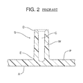
- a typical heat stake S includes a tapered cylindrical sidewall W having a hollow core C. More specifically, the taper is toward the distal end D of the heat stake S and results from a design draft to allow the plastic part P to be removed from an injection molding tool.
- the wall W of the heat stake S includes a greater cross-sectional area and perimeter at the proximal end E adjacent the plastic part P than at the distal end D.
- the increased cross-sectional area of the heat stake S at the proximal end E where the heat stake S is joined with the plastic part P has a tendency to promote sink marks in the surface A of the plastic part P. This increases material usage, product waste and cost.
- This document relates to a new and improved heat stake for a plastic part that effectively reduces the cross-sectional area of the heat stake at the proximal end where the heat stake is joined with the plastic part thereby avoiding sink marks in the A surface of the plastic part even when the plastic part includes relatively thin cross sections.
- this is achieved without adding tooling actions in the injection mold tools to form the associated undercut features.
- a heat stake for a plastic part.
- That heat stake comprises a body having a proximal end, a flared section and a distal end.
- the proximal end has a first cross-sectional area A 1 while the flared section has a second cross-sectional area A 2 where A 1 ⁇ A 2 .
- the distal end includes a dual taper effectively providing more material to melt during sonic-staking without increasing hole size. Accordingly, a more robust connection may be provided.
- the body of the heat stake may also define a first slot extending between the proximal end and the distal end.
- the body of the heat stake may also define a second slot extending between the proximal end and the distal end.
- the body of the heat stake may also define a third slot extending between the proximal end and the distal end.
- the body may include a hollow core.
- the first slot, the second slot and the third slot may be radially arrayed around the body.
- the body may include a first section extending between the first slot and the second slot, a second section extending between the second slot and the third slot and a third section extending between the third slot and the first slot.
- a plastic part including the heat stake.
- the heat stake for a plastic part may comprise a body having a proximal end, a flared section and a distal end wherein the proximal end has a first perimeter P 1 and the flared section has a second perimeter P 2 where P 1 ⁇ P 2 .
- the distal end includes a dual taper comprising an inner lead-in and an outer lead-in.
- the body defines a first slot extending between the proximal end and the distal end.
- the body may also define a second slot extending between the proximal end and the distal end.
- the body may define a third slot extending between the proximal end and the distal end.
- the body may include a hollow core.
- the first slot, the second slot and the third slot may all be radially arrayed around the body.
- the body may include a first section extending between the first slot and the second slot, a second section extending between the second slot and the third slot and a third section extending between the third slot and the first slot.
- a method is provided of eliminating heat stake sink marks in a plastic part. That method comprises the steps of (a) forming a body of the heat stake with a first cross-sectional area A 1 at a proximal end and a second cross-sectional area A 2 at a flared section where A 1 ⁇ A 2 and (b) forming at least one longitudinal slot in the body of the heat stake extending from the proximal end to the distal end.
- FIG. 1 is a perspective view of a plastic part incorporating a prior art heat stake including a cylindrical wall with a draft that tapers from the proximal end of the heat stake attached to the body of the plastic part toward the distal end of the heat stake in order to allow removal of the plastic part from an injection tool or mold.
- FIG. 2 is a cross-sectional view of the prior art heat stake illustrated in FIG. 1 .
- FIG. 3 is a perspective view of a plastic part including the new and improved heat stake.
- FIG. 4 is a cross-sectional view through the new and improved heat stake illustrated in FIG. 3 .
- FIGS. 5 a -5 d are a series of schematic illustrations showing how the new and improved heat stake with a greater cross-sectional area at the distal end thereof bends or folds inward to allow for removal or ejection from the injection tool or mold.
- the heat stake 12 includes a body 14 having a proximal end 16 joined to the B surface 18 of the plastic part 10 and a distal end 20 opposite the proximal end and a flared section 21 therebetween.
- the proximal end 16 has a first cross-sectional area A 1 and the flared section 21 has a second cross-sectional area A 2 where A 1 ⁇ A 2 .
- the proximal end 16 has a first perimeter P 1 and the flared section 21 has a second perimeter P 2 where P 1 ⁇ P 2 .
- the body 14 comprises a first section 22 , a second section 24 and a third section 26 .
- the body 14 also defines a first slot 28 , a second slot 30 and a third slot 32 .
- the first slot 28 , the second slot 30 and the third slot 32 all extend between the proximal end 16 and the distal end 20 .
- first section 22 extends between the first slot 28 and the second slot 30 .
- the second section 24 extends between the second slot 30 and the third slot 32 .
- the third section 26 extends between the third slot 32 and the first slot 28 .
- the body 14 incorporates a hollow core 34 in communication with the first slot 28 , the second slot 30 and the third slot 32 .
- the increase in the second cross-sectional area A 2 at the flared section 21 of the body 14 is provided by an increase in the outer diameter of the body 14 at the distal end (i.e. an outward taper).
- the body 14 includes a greater amount of material at the flared section 21 for the purposes of staking the plastic part 10 to another work piece.
- the body 14 includes less material at the proximal end 16 to resist the formation of sink marks during the molding process in the A surface 36 of the plastic part 10 .
- the dual tapered distal end 20 includes an inner lead-in 38 and an outer lead-in 40 .
- This additional material is provided without further increasing the outer diameter of the body 14 .
- more material is provided for melting around a hole of equal size.
- a stronger or more robust connection is provided with improved clamp load.
- FIG. 5 a illustrates the plastic part 10 in the injection mold or tool M immediately following injection of the plastic material into the mold tool.
- the core mold section C is withdrawn from the first mold section S 1 (note action arrow A). This opens the hollow core 34 of the heat stake 12 .
- the mold tool M is opened by displacing the second mold section S 2 away from the A surface 36 of the plastic part 10 . See FIG. 5 c .
- the plastic part is then ejected from the first mold section S 1 (see action arrow B).
- first section 22 , second section 24 and third section 26 of the body 14 bend inward (note action arrow D) into the core 34 or space vacated by the core mold section C allowing the necessary clearance for the larger distal end 20 of the heat stake 12 to move through the narrow mold passage P that forms the smaller diameter portion of the body 14 of the heat stake.
- first, second and third sections 22 , 24 , 26 of the body 14 is accommodated by the first, second and third slots 28 , 30 , 32 .
- the heat stake 12 to be formed with a larger outer diameter at the distal end 20 and an increase in material for the staking process while also minimizing the amount of material in the body 14 at the proximal end 16 so as to prevent the formation of sink marks in the A surface 36 of the plastic part 10 .
- a method of eliminating heat stake sink marks in a plastic part 10 includes the step of forming a body 14 of a heat stake 10 with a first cross-sectional area A 1 at a proximal end 16 and a second cross-sectional area A 2 at a flared section 21 where A 1 ⁇ A 2 . Further, the method includes forming at least one longitudinal slot 28 , 30 , 32 in the body 14 of the heat stake 10 extending from the proximal end 16 to the distal end 20 .
- the heat stake 10 illustrated in drawing FIGS. 3-5 d includes a body 14 having three sections 22 , 24 , 26 and three slots 28 , 30 , 32 .
- the body 14 may include a different number of slots and sections.
- the sections 22 , 24 , 26 all extend through arcs of the same dimension. It should be appreciated that the sections 22 , 24 , 26 and even the slots 28 , 30 , 32 may all extend through arcs of different dimension.
- the illustrated heat stake 10 has a generally cylindrically shaped body but the body could include other cross-sectional shapes. All such modifications and variations are within the scope of the appended claims when interpreted in accordance with the breadth to which they are fairly, legally and equitably entitled.
Abstract
Description
Claims (15)
Priority Applications (3)
| Application Number | Priority Date | Filing Date | Title |
|---|---|---|---|
| US15/287,901 US10493716B2 (en) | 2016-10-07 | 2016-10-07 | Heat stake and method of eliminating heat stake sink marks in a plastic part |
| CN201721267495.XU CN207825340U (en) | 2016-10-07 | 2017-09-29 | Hot molten column and plastic part for plastic part |
| DE202017106026.8U DE202017106026U1 (en) | 2016-10-07 | 2017-10-04 | Hot stamping for a plastic part |
Applications Claiming Priority (1)
| Application Number | Priority Date | Filing Date | Title |
|---|---|---|---|
| US15/287,901 US10493716B2 (en) | 2016-10-07 | 2016-10-07 | Heat stake and method of eliminating heat stake sink marks in a plastic part |
Publications (2)
| Publication Number | Publication Date |
|---|---|
| US20180099446A1 US20180099446A1 (en) | 2018-04-12 |
| US10493716B2 true US10493716B2 (en) | 2019-12-03 |
Family
ID=60419492
Family Applications (1)
| Application Number | Title | Priority Date | Filing Date |
|---|---|---|---|
| US15/287,901 Active 2037-04-29 US10493716B2 (en) | 2016-10-07 | 2016-10-07 | Heat stake and method of eliminating heat stake sink marks in a plastic part |
Country Status (3)
| Country | Link |
|---|---|
| US (1) | US10493716B2 (en) |
| CN (1) | CN207825340U (en) |
| DE (1) | DE202017106026U1 (en) |
Cited By (1)
| Publication number | Priority date | Publication date | Assignee | Title |
|---|---|---|---|---|
| US11971598B2 (en) | 2022-02-18 | 2024-04-30 | Commscope Technologies Llc | Tray arrangements for cassettes |
Families Citing this family (1)
| Publication number | Priority date | Publication date | Assignee | Title |
|---|---|---|---|---|
| DE102021122734A1 (en) | 2021-09-02 | 2023-03-02 | Te Connectivity Germany Gmbh | Casting tool, method and use of a casting tool for reshaping a cast part and cast part |
Citations (6)
| Publication number | Priority date | Publication date | Assignee | Title |
|---|---|---|---|---|
| US1475827A (en) | 1922-01-17 | 1923-11-27 | Leo J Hogarty | Securing device |
| US2065333A (en) | 1936-05-12 | 1936-12-22 | Arthur A Kirley | Expansion rivet |
| US3638259A (en) | 1967-02-01 | 1972-02-01 | Eibes Kerb Konus Gmbh | Method for making blind rivets |
| US7070378B2 (en) * | 2002-01-09 | 2006-07-04 | Intier Automotive Inc. | Heatstake |
| US20070074592A1 (en) * | 2005-09-30 | 2007-04-05 | Santos Roberto S | Sensor mounting structure allowing for adjustment of sensor position |
| CN201325149Y (en) | 2008-12-30 | 2009-10-14 | 深圳创维-Rgb电子有限公司 | Sink-mark prevention mechanism of injection mold |
-
2016
- 2016-10-07 US US15/287,901 patent/US10493716B2/en active Active
-
2017
- 2017-09-29 CN CN201721267495.XU patent/CN207825340U/en active Active
- 2017-10-04 DE DE202017106026.8U patent/DE202017106026U1/en active Active
Patent Citations (6)
| Publication number | Priority date | Publication date | Assignee | Title |
|---|---|---|---|---|
| US1475827A (en) | 1922-01-17 | 1923-11-27 | Leo J Hogarty | Securing device |
| US2065333A (en) | 1936-05-12 | 1936-12-22 | Arthur A Kirley | Expansion rivet |
| US3638259A (en) | 1967-02-01 | 1972-02-01 | Eibes Kerb Konus Gmbh | Method for making blind rivets |
| US7070378B2 (en) * | 2002-01-09 | 2006-07-04 | Intier Automotive Inc. | Heatstake |
| US20070074592A1 (en) * | 2005-09-30 | 2007-04-05 | Santos Roberto S | Sensor mounting structure allowing for adjustment of sensor position |
| CN201325149Y (en) | 2008-12-30 | 2009-10-14 | 深圳创维-Rgb电子有限公司 | Sink-mark prevention mechanism of injection mold |
Non-Patent Citations (1)
| Title |
|---|
| English Machine Translation of CN201325149Y. |
Cited By (1)
| Publication number | Priority date | Publication date | Assignee | Title |
|---|---|---|---|---|
| US11971598B2 (en) | 2022-02-18 | 2024-04-30 | Commscope Technologies Llc | Tray arrangements for cassettes |
Also Published As
| Publication number | Publication date |
|---|---|
| US20180099446A1 (en) | 2018-04-12 |
| CN207825340U (en) | 2018-09-07 |
| DE202017106026U1 (en) | 2017-11-02 |
Similar Documents
| Publication | Publication Date | Title |
|---|---|---|
| US6596240B2 (en) | Pipette tip for easy mounting and ejecting from a pipette | |
| US20060188602A1 (en) | Collapsible core assembly for a molding apparatus | |
| US20140033533A1 (en) | Method for manufacturing hollow engine valve | |
| US9194419B2 (en) | Insert kit and installation method | |
| US10493716B2 (en) | Heat stake and method of eliminating heat stake sink marks in a plastic part | |
| JP2018083429A5 (en) | Mold for injection and injection mold | |
| WO2006084846A3 (en) | Method for primary molding a molded part and molded part, especially nut, produced by primary molding | |
| KR20150097406A (en) | Method and mold for producing an opening in a fiber composite component | |
| EP3456431B1 (en) | Mold pin for manufacturing tube yoke | |
| KR20160114178A (en) | Blind rivet arrangement and joint | |
| TWI485017B (en) | Engine valve forging system | |
| CN105934295B (en) | Method for fixing multiple workpiece by hollow rivet element | |
| CN106493186B (en) | A kind of molding die of automobile steering device connecting rod | |
| JP5558270B2 (en) | Insert metal fitting and manufacturing method thereof | |
| JP2010167459A (en) | Prismatic tube container forming method, and punch therefor | |
| EP3245036B1 (en) | Method for converting a design of an original preform and a related mold stack for the molding thereof | |
| CN112840133B (en) | Resin panel and method for manufacturing structure | |
| EP3900669A1 (en) | Method for manufacturing interdental cleaning tool | |
| CN212764552U (en) | Molded object, motor, and apparatus for manufacturing molded object | |
| WO2021111833A1 (en) | Resin molded article and mold | |
| CN114340812B (en) | Extrusion molding method and extrusion molding device for non-uniform thickness pipes | |
| US20150352754A1 (en) | Method of manufacturing resin molded body, and press die for resin molding | |
| JP2004042295A (en) | Ejector pin for mold | |
| JP2005305868A (en) | Method for molding cylindrical member and mold for molding the same | |
| US20160076571A1 (en) | Insert kit and installation method |
Legal Events
| Date | Code | Title | Description |
|---|---|---|---|
| AS | Assignment |
Owner name: FORD GLOBAL TECHNOLOGIES, LLC, MICHIGAN Free format text: ASSIGNMENT OF ASSIGNORS INTEREST;ASSIGNORS:QI, LIYING;WEBB, JEFFREY PETER;LIU, FRANK QUIUKUI;AND OTHERS;SIGNING DATES FROM 20160928 TO 20161005;REEL/FRAME:039964/0179 |
|
| STPP | Information on status: patent application and granting procedure in general |
Free format text: NON FINAL ACTION MAILED |
|
| STPP | Information on status: patent application and granting procedure in general |
Free format text: RESPONSE TO NON-FINAL OFFICE ACTION ENTERED AND FORWARDED TO EXAMINER |
|
| STPP | Information on status: patent application and granting procedure in general |
Free format text: FINAL REJECTION MAILED |
|
| STPP | Information on status: patent application and granting procedure in general |
Free format text: RESPONSE AFTER FINAL ACTION FORWARDED TO EXAMINER |
|
| STPP | Information on status: patent application and granting procedure in general |
Free format text: NOTICE OF ALLOWANCE MAILED -- APPLICATION RECEIVED IN OFFICE OF PUBLICATIONS |
|
| STPP | Information on status: patent application and granting procedure in general |
Free format text: PUBLICATIONS -- ISSUE FEE PAYMENT VERIFIED |
|
| STCF | Information on status: patent grant |
Free format text: PATENTED CASE |
|
| MAFP | Maintenance fee payment |
Free format text: PAYMENT OF MAINTENANCE FEE, 4TH YEAR, LARGE ENTITY (ORIGINAL EVENT CODE: M1551); ENTITY STATUS OF PATENT OWNER: LARGE ENTITY Year of fee payment: 4 |