EP3530256A1 - Drinking straw for administration of an active agent - Google Patents
Drinking straw for administration of an active agent Download PDFInfo
- Publication number
- EP3530256A1 EP3530256A1 EP18000176.0A EP18000176A EP3530256A1 EP 3530256 A1 EP3530256 A1 EP 3530256A1 EP 18000176 A EP18000176 A EP 18000176A EP 3530256 A1 EP3530256 A1 EP 3530256A1
- Authority
- EP
- European Patent Office
- Prior art keywords
- drinking straw
- membrane
- wall
- straw according
- closure element
- Prior art date
- Legal status (The legal status is an assumption and is not a legal conclusion. Google has not performed a legal analysis and makes no representation as to the accuracy of the status listed.)
- Withdrawn
Links
Images


Classifications
-
- A—HUMAN NECESSITIES
- A47—FURNITURE; DOMESTIC ARTICLES OR APPLIANCES; COFFEE MILLS; SPICE MILLS; SUCTION CLEANERS IN GENERAL
- A47G—HOUSEHOLD OR TABLE EQUIPMENT
- A47G21/00—Table-ware
- A47G21/18—Drinking straws or the like
- A47G21/183—Drinking straws or the like with means for changing the flavour of the liquid
-
- A—HUMAN NECESSITIES
- A61—MEDICAL OR VETERINARY SCIENCE; HYGIENE
- A61J—CONTAINERS SPECIALLY ADAPTED FOR MEDICAL OR PHARMACEUTICAL PURPOSES; DEVICES OR METHODS SPECIALLY ADAPTED FOR BRINGING PHARMACEUTICAL PRODUCTS INTO PARTICULAR PHYSICAL OR ADMINISTERING FORMS; DEVICES FOR ADMINISTERING FOOD OR MEDICINES ORALLY; BABY COMFORTERS; DEVICES FOR RECEIVING SPITTLE
- A61J7/00—Devices for administering medicines orally, e.g. spoons; Pill counting devices; Arrangements for time indication or reminder for taking medicine
- A61J7/0015—Devices specially adapted for taking medicines
- A61J7/0038—Straws
-
- A—HUMAN NECESSITIES
- A61—MEDICAL OR VETERINARY SCIENCE; HYGIENE
- A61M—DEVICES FOR INTRODUCING MEDIA INTO, OR ONTO, THE BODY; DEVICES FOR TRANSDUCING BODY MEDIA OR FOR TAKING MEDIA FROM THE BODY; DEVICES FOR PRODUCING OR ENDING SLEEP OR STUPOR
- A61M2202/00—Special media to be introduced, removed or treated
- A61M2202/06—Solids
- A61M2202/064—Powder
Definitions
- the present invention relates to a drinking straw for the administration of active ingredients such as dietary supplements or drugs.
- the drug to be administered is already in the drinking straw and is sucked with a liquid from the drinking straw into the mouth and then swallowed. This regularly facilitates the intake of the active substance because it can be swallowed much easier.
- the perceived unpleasant taste of the drug can be covered by the liquid by the inclusion of the active ingredient as an in-situ suspension with a liquid.
- Drinking straws for the administration of active ingredients are for example from WO 98/51259 A1 or the WO 2006/079648 A1 known.
- the straws described therein have a wall with a first and a second end, wherein the wall at the first and / or the second end may have a stiffener.
- a controller Inside the drinking straw is a controller. This controller prevents the active ingredient in the drinking straw from falling out of the drinking straw.
- the controller is originally located in the lower part of the drinking straw. While drinking, the controller will be sucked upwards and will remain in this new position even after the drinking straw has been set down. As a result of the position of the controller, it can be easily checked whether the active substance has already been completely taken or not.
- the controllers are usually designed as an open-pored solid and made of a gas and / or liquid-permeable material.
- the controllers can be designed in the form of a sponge or in the form of a fiber braid.
- the controllers have been developed so far for the administration of active ingredients in the form of pellets.
- the pellets used have a certain minimum size and a defined particle size distribution.
- active ingredients in the form of fine powders may leak through the controller and leak out, for example, into the packaging of the drinking straw before the beginning of the suction process.
- the administration of active ingredients in the form of fine powders with a particle size below 210 microns is therefore not possible with the described controllers.
- the present invention seeks to provide a drinking straw for the administration of an active ingredient with which finely powdered drugs can be safely administered.
- the drinking straw according to the invention for the administration of an active substance has a wall with a first end and with a second end and a closure element, by means of which one of the two ends of the wall can be detachably closed.
- a membrane is present in the region of the other end of the wall. The active substance can rest on this membrane, so that the active substance is enclosed between the membrane and the closure element in the interior of the wall.
- the membrane may be formed liquid-permeable.
- the membrane can therefore remain intact during the drinking process, since the liquid that is drunk to receive the active ingredient, can pass through the membrane. In this way it can also be ensured that no unwanted solids are inadvertently taken up.
- the membrane may form an opening through which liquid can pass through the membrane.
- the membrane can in this case, for example, burst open or tear, which can form the corresponding opening.
- the membrane may preferably have a predetermined breaking point, which may in particular be designed as a material dilution.
- a predetermined breaking point in the form of a material dilution can be done for example by the removal of material by means of a laser.
- the predetermined breaking point should be located in particular in the central region of the membrane and not at the edge regions. In this way it can be prevented that the membrane is completely or partially detached from the wall of the drinking straw.
- the membrane in a first embodiment on the end face of the wall of the Drinking straw attached.
- Such attachment can be done for example via a suitable adhesive or by sealing the membrane on the front page.
- the membrane may be arranged in a preferred embodiment a piece offset inwards and thus secured to the inner wall of the drinking straw.
- the membrane may be fastened by means of a clamping element on the inner wall of the drinking straw.
- a clamping element may in particular have a pipe socket whose circular outer diameter is slightly smaller than the circular inner diameter of the wall of the drinking straw. If such a pipe socket is provided with a continuous slot in the longitudinal direction, the pipe socket expands, so that its outer diameter increases.
- the pipe socket can be compressed in this case by only a small application of force and be introduced in this way a little way into the interior of the wall. After positioning the pipe socket, this can expand and press close to the inner wall of the drinking straw.
- a membrane that has been placed over the pipe socket can be securely fixed within the drinking straw.
- the membrane can lie loosely over the pipe socket of the clamping element.
- the membrane may also be attached to the pipe socket by means of an adhesive, for example. It would also be possible to seal the membrane on the pipe socket.
- the corresponding end of the wall is closed by means of a closure element.
- the closure element may be immediately before taking the active ingredient removed from the patient or a helper, so that this end of the drinking straw can be taken from the patient's mouth.
- the closure element may be a cap in the simplest case, which can be slipped over the end of the wall frictionally.
- the closure element may preferably be formed as a foil.
- the film can be releasably secured to the front side of the wall. Such attachment can be done for example via a suitable adhesive or by sealing the film.
- the closure element may be releasably secured to the outer wall of the drinking straw.
- This can be realized for example by a shrink film, in particular by a shrink tube or a shrink cap, as a closure element.
- the closure element can also be fixed with an additional adhesive tape on the outer wall of the drinking straw.
- the membrane-side end of the wall can be closed by a barrier layer.
- the barrier layer should be airtight so that air can not be inadvertently sucked through the drinking straw. This could result in the membrane being able to accidentally break even by aspirating air. In this case, there is a risk that the patient inhales the finely powdered active ingredient.
- the barrier layer should be water-soluble so that it dissolves on contact with a beverage. In this way, after a brief standing of the drinking straw in a drink, the full functionality of the drinking straw can be guaranteed. After dissolution of the barrier layer, the beverage can be absorbed by the drinking straw, whereby the absorption of the active ingredient is made possible.
- the barrier layer can in particular consist of a taste-neutral polymer, for example of gelatin.
- the wall of the drinking straw according to the invention may have at the first and / or at the second end a stiffening, as for example from the WO 2006/079648 A1 already known.
- a drinking straw in the sense of this invention is any drinking straw with which a liquid can be sucked through the mouth of a person.
- the drinking straw according to the invention may preferably consist of a thermoplastic or thermosetting plastic. If the content of the drinking straw is to be visible, the wall of the drinking straw may consist of a transparent material, in particular of a colorless transparent material. In this way it can be seen immediately whether the active ingredient is still in the drinking straw, or whether it has already been taken.
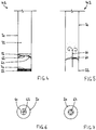
- the drinking straw 10 has a wall 20 with a first, lower end 22 and a second, upper end 24.
- the lower end 22 can be placed in a container with a drinkable liquid.
- the upper end 24 is placed in the mouth so that the liquid can be absorbed by the drinking straw 10.
- the upper end 24 of the wall 20 is closed by a closure element in the form of a cap 30 before use.
- the cap 30 is frictionally seated on the upper end 24 of the wall 20.
- a membrane 40 is present in the region of the lower end 22 of the wall 20, a membrane 40 is present.
- the membrane 40 is formed sufficiently dense, so that even finely powdered active ingredients 12 can not trickle through the membrane 40.
- the membrane 40 is made so smooth that the active ingredients 12 can not adhere to the membrane 40.
- the membrane 40 therefore allows the administration of finely powdered, active ingredient-containing formulations by the drinking straw 10 according to the invention.
- the active ingredient-containing formulations may contain a single active ingredient or a mixture of different active ingredients.
- the formulations may contain additional fillers in addition to the active ingredients in both cases.
- the membrane 40 is attached in the present example to the inner wall 42 of the drinking straw 10.
- the membrane 40 is stretched over a clamping element in the form of a pipe socket 44.
- the pipe socket 44 has an outer diameter 46, which is slightly smaller than the inner diameter 48 of the wall 20 of the drinking straw 10.
- a continuous slot 50 in the longitudinal direction 52 is formed in the pipe socket 44. Through this slot 50, the pipe socket 44 may extend a little way, so that it rests tightly against the inside 42 of the wall 20.
- the membrane 40 located between the outside of the pipe socket 44 and the inside 42 of the wall 20 is thus fixed at the desired position.
- the drug 12 to be administered can rest on the membrane 40.
- the active ingredient 12 is then located between the membrane 40 and the cap 30 in the interior of the drinking straw 10 (see Fig. 1 ).
- it may additionally be packed in an outer packaging, not shown here, for example in a foil bag.
- the membrane 40 is in the embodiment according to Fig. 1 to 3 formed liquid permeable.
- the liquid to be drunk can thus be sucked through the membrane 40.
- the active ingredient 12 to be administered can be dissolved or suspended in the liquid and thus reach the patient's mouth.
- the membrane 40 remains intact and lies after the end of the drinking process (see Fig. 2 ) unchanged.
- a second embodiment of the drinking straw 10.2 according to the invention is shown.
- the membrane 60 is welded in this case to the inner wall 42 of the drinking straw 10.2.
- the membrane 60 has a predetermined breaking point in the form of a material dilution 62.
- the material dilution 62 can be produced, for example, by means of a laser. By means of a laser, individual layers of the membrane 60 can be removed, so that, although it can still serve as a seal for the active substance 12 to be administered, it tears when subjected to a pressure or suction load.
- the material dilution 62 is provided in the present example in the central region of the membrane 60.
- the membrane 60 thereby tears in the middle, but remains securely attached to the inner wall 42 of the drinking straw 10.2 at the edge. This can ensure that the membrane 60 is not accidentally ruptured so that parts of the membrane 60 can be sucked with.
- the material dilution 62 is executed crosswise in the present example case (see Fig. 6 ), so that a flat opening 64 (see Fig. 7 ) as the membrane 60 breaks. Through this opening 64, the liquid can be absorbed (arrow 66).
- the administered Active substance 12 entrained and can also be absorbed and swallowed.
- the membrane 60 is like the membrane 40 also formed sufficiently dense, so that even finely powdered active ingredients 12 can not trickle through the membrane 60. At the same time, the membrane 60 is made so smooth that the active ingredients 12 can not adhere to the membrane 60.
- a barrier layer 70 is provided at the membrane-side lower end 22 of the wall 20 in the present embodiment.
- the barrier layer 70 closes the inner space 32 of the drinking straw 10 downwards in an airtight manner. In this way it can be prevented that the membrane 60 tears already during the intake of air and thereby the active ingredient 12 could be inhaled by mistake.
- the barrier layer 70 dissolves after a short time of standing in a beverage. Then the drink can be absorbed by the drinking straw 10. Only then does membrane 60 rupture and drug 12 can be ingested and swallowed.
- a third embodiment of the drinking straw 10.3 according to the invention is shown.
- the membrane 60.3 is also attached in this case to the inner wall 42 of the drinking straw 10.3.
- the membrane 60.3 has a predetermined breaking point in the form of a laser perforation 68 (see Fig. 10 ).
- the laser perforation 68 ruptures and a circular opening 64.3 is formed in the middle region of the membrane 60.3 (see FIG Fig. 11 ).
- the liquid can be absorbed (arrow 66).
- the drug 12 to be administered is entrained and can also be absorbed and swallowed.
- the barrier layer 70 is first provided at the lower end 22 of the wall 20 (see FIG. 10 ).
- the barrier layer 70 could also in the first embodiment according to Fig. 1 to 4 be provided.
- the membrane 40, 60, 60.3 could also be attached to the end face 26 of the lower end 22 of the wall 20.
- FIGS. 12 and 13 two alternative closure elements for the upper end 24 of the wall 20 are shown.
- the closure element is designed as a sealing film 80.
- the sealing film 80 is releasably secured to the end face 28 of the upper end 24 of the wall 20.
- the sealing film 80 has a tab 82 for this purpose. By means of the tab 82, the sealing film 80 can be deducted from the end face 28 in order to absorb the active ingredient 12 can.
- the closure element is designed as a shrink cap 84.
- the shrink cap 84 may be withdrawn from the wall 20 to expose the top end 22 of the wall 20.
- the shrink cap 84 could also include one or more perforations that may facilitate rupture and removal of the shrink cap 84.
- a shrink tube could be used.
Abstract
Die Erfindung betrifft einen Trinkhalm (10) zur Verabreichung eines Wirkstoffs (12). Der Trinkhalm (10) besitzt eine Wandung (20) mit einem ersten Ende und mit einem zweiten Ende. Eines der beiden Enden der Wandung (20) kann mit einem Verschlusselement (30) lösbar verschlossen werden. Im Bereich des anderen Endes der Wandung (20) ist eine Membran (40) vorhanden, auf der der Wirkstoff (12) aufliegt.The invention relates to a drinking straw (10) for administering an active substance (12). The drinking straw (10) has a wall (20) with a first end and with a second end. One of the two ends of the wall (20) can be releasably closed with a closure element (30). In the region of the other end of the wall (20) there is a membrane (40) on which the active substance (12) rests.
Description
Die vorliegende Erfindung betrifft einen Trinkhalm zur Verabreichung von Wirkstoffen wie beispielsweise von Nahrungsergänzungsmitteln oder von Medikamenten. Der zu verabreichende Wirkstoff befindet sich bereits in dem Trinkhalm und wird mit einer Flüssigkeit aus dem Trinkhalm in den Mund gesaugt und anschließend geschluckt. Dies erleichtert regelmäßig die Einnahme des Wirkstoffs, weil dieser sehr viel leichter geschluckt werden kann. Durch die Aufnahme des Wirkstoffs als in-situ-Suspension mit einer Flüssigkeit kann darüber hinaus der als unangenehm empfundene Geschmack des Wirkstoffs durch die Flüssigkeit überdeckt werden.The present invention relates to a drinking straw for the administration of active ingredients such as dietary supplements or drugs. The drug to be administered is already in the drinking straw and is sucked with a liquid from the drinking straw into the mouth and then swallowed. This regularly facilitates the intake of the active substance because it can be swallowed much easier. In addition, the perceived unpleasant taste of the drug can be covered by the liquid by the inclusion of the active ingredient as an in-situ suspension with a liquid.
Trinkhalme zur Verabreichung von Wirkstoffen sind beispielsweise aus der
Die Controller sind in der Regel als offenporige Festkörper ausgebildet und aus einem gas- und/oder flüssigkeitsdurchlässigem Material. So können die Controller beispielsweise in Form eines Schwämmchens oder in Form eines Fasergeflechts ausgebildet sein.The controllers are usually designed as an open-pored solid and made of a gas and / or liquid-permeable material. For example, the controllers can be designed in the form of a sponge or in the form of a fiber braid.
Die Controller wurden dabei bislang für die Verabreichung von Wirkstoffen in Form von Pellets entwickelt. Die verwendeten Pellets weisen dabei eine bestimmte Mindestgröße und eine definierte Partikelgrößenverteilung auf. Bei der Verabreichung von Wirkstoffen in Form von feinen Pulvern kann es dagegen vorkommen, dass diese durch den Controller durchsickern und bereits vor dem Beginn des Saugvorgangs beispielsweise in die Verpackung des Trinkhalms austreten. Auch kann regelmäßig nicht gewährleistet werden, dass die feinen Pulver vollständig eingenommen werden, da ein Teil des feinen Pulvers in dem Controller hängen bleiben kann. Dies kann insbesondere bei der Verabreichung von potentiell toxischen Medikamenten - beispielsweise bei Onkologika - zu einer Gefährdung Dritter führen, da diese Dritte so versehentlich mit dem Wirkstoff in Kontakt kommen können. Die Verabreichung von Wirkstoffen in Form von feinen Pulvern mit einer Partikelgröße unter 210 Mikrometern ist daher mit den beschriebenen Controllern nicht möglich.The controllers have been developed so far for the administration of active ingredients in the form of pellets. The pellets used have a certain minimum size and a defined particle size distribution. When administering active ingredients in the form of fine powders, on the other hand, they may leak through the controller and leak out, for example, into the packaging of the drinking straw before the beginning of the suction process. Also, it can not be guaranteed on a regular basis that the fine powders are completely taken, because some of the fine powder may get stuck in the controller. This can lead to a risk to third parties, in particular when administering potentially toxic medicaments - for example oncologics - since these thirds may thus inadvertently come into contact with the active ingredient. The administration of active ingredients in the form of fine powders with a particle size below 210 microns is therefore not possible with the described controllers.
Ausgehend von diesem vorbekannten Stand der Technik lag der Erfindung die Aufgabe zugrunde, einen Trinkhalm zur Verabreichung eines Wirkstoffs anzugeben, mit dem auch feinpulvrige Wirkstoffe sicher verabreicht werden können.Based on this prior art, the present invention seeks to provide a drinking straw for the administration of an active ingredient with which finely powdered drugs can be safely administered.
Der erfindungsgemäße Trinkhalm zur Verabreichung eines Wirkstoffs ist durch die Merkmale des Hauptanspruchs 1 gegeben. Sinnvolle Weiterbildungen der Erfindung sind Gegenstand von sich an diesen Anspruch anschließenden weiteren Ansprüchen.The drinking straw according to the invention for the administration of an active ingredient is given by the features of the main claim 1. Useful developments of the invention are the subject of further claims that follow this claim.
Der erfindungsgemäße Trinkhalm zur Verabreichung eines Wirkstoffes besitzt eine Wandung mit einem ersten Ende und mit einem zweiten Ende und ein Verschlusselement, durch das eines der beiden Enden der Wandung lösbar verschlossen werden kann. Erfindungsgemäß ist im Bereich des anderen Endes der Wandung eine Membran vorhanden. Auf dieser Membran kann der Wirkstoff aufliegen, so dass der Wirkstoff zwischen der Membran und dem Verschlusselement im Innenraum der Wandung eingeschlossen ist. Die Verwendung einer Membran anstelle des Controllers ermöglicht es, auch feine Pulver mittels des erfindungsgemäßen Trinkhalms sicher und exakt dosiert verabreichen zu können.The drinking straw according to the invention for the administration of an active substance has a wall with a first end and with a second end and a closure element, by means of which one of the two ends of the wall can be detachably closed. According to the invention, a membrane is present in the region of the other end of the wall. The active substance can rest on this membrane, so that the active substance is enclosed between the membrane and the closure element in the interior of the wall. The use of a membrane instead of the controller makes it possible to administer even fine powders safely and accurately dosed by means of the drinking straw according to the invention.
In einer ersten Ausführungsform kann die Membran flüssigkeitsdurchlässig ausgebildet sein. Die Membran kann daher während des Trinkvorgangs intakt bleiben, da die Flüssigkeit, die zur Aufnahme des Wirkstoffs getrunken wird, durch die Membran gelangen kann. Auf diese Weise kann auch sichergestellt werden, dass keine unerwünschten Feststoffe versehentlich mit aufgenommen werden.In a first embodiment, the membrane may be formed liquid-permeable. The membrane can therefore remain intact during the drinking process, since the liquid that is drunk to receive the active ingredient, can pass through the membrane. In this way it can also be ensured that no unwanted solids are inadvertently taken up.
In einer zweiten Ausführungsform kann die Membran während des Saugvorgangs eine Öffnung bilden, durch die Flüssigkeit durch die Membran durchtreten kann. Die Membran kann in diesem Fall beispielsweise kontrolliert aufplatzen oder reißen, wodurch sich die entsprechende Öffnung bilden kann. Um die Bildung der Öffnung kontrolliert ablaufen zu lassen, kann die Membran vorzugsweise eine Sollbruchstelle aufweisen, die insbesondere als Materialverdünnung ausgebildet sein kann. Eine solche Sollbruchstelle in Form einer Materialverdünnung kann beispielsweise durch das Abtragen von Material mittels eines Lasers erfolgen. Die Sollbruchstelle sollte sich insbesondere im mittleren Bereich der Membran befinden und nicht an deren Randbereichen. Auf diese Weise kann verhindert werden, dass sich die Membran ganz oder teilweise von der Wandung des Trinkhalms löst.In a second embodiment, during the suction process, the membrane may form an opening through which liquid can pass through the membrane. The membrane can in this case, for example, burst open or tear, which can form the corresponding opening. In order to allow the formation of the opening to proceed in a controlled manner, the membrane may preferably have a predetermined breaking point, which may in particular be designed as a material dilution. Such a predetermined breaking point in the form of a material dilution can be done for example by the removal of material by means of a laser. The predetermined breaking point should be located in particular in the central region of the membrane and not at the edge regions. In this way it can be prevented that the membrane is completely or partially detached from the wall of the drinking straw.
Unabhängig von der Ausgestaltung der Membran kann die Membran in einer ersten Ausführungsform an der Stirnseite der Wandung des Trinkhalms befestigt sein. Eine solche Befestigung kann beispielsweise über ein geeignetes Klebemittel oder durch Aufsiegeln der Membran auf die Stirnseite erfolgen.Regardless of the design of the membrane, the membrane in a first embodiment on the end face of the wall of the Drinking straw attached. Such attachment can be done for example via a suitable adhesive or by sealing the membrane on the front page.
Um eine nachträgliche Manipulation der Membran nach der Befüllung des Trinkhalms mit dem Wirkstoff zu vermeiden, kann die Membran in einer bevorzugten Ausführungsform ein Stück nach innen versetzt angeordnet und somit an der Innenwandung des Trinkhalms befestigt sein.In order to avoid a subsequent manipulation of the membrane after the filling of the drinking straw with the active ingredient, the membrane may be arranged in a preferred embodiment a piece offset inwards and thus secured to the inner wall of the drinking straw.
In einer konstruktiv besonders einfachen Ausführungsform kann die Membran mittels eines Klemmelements an der Innenwandung des Trinkhalms befestigt sein. Ein solches Klemmelement kann insbesondere einen Rohrstutzen besitzen, dessen kreisförmiger Außendurchmesser geringfügig kleiner ist als der kreisförmige Innendurchmesser der Wandung des Trinkhalm. Wird ein solcher Rohrstutzen mit einem durchgehenden Schlitz in Längsrichtung versehen, dehnt sich der Rohrstutzen aus, so dass sich dessen Außendurchmesser vergrößert. Der Rohrstutzen kann in diesem Fall durch lediglich geringe Kraftaufwendung zusammengedrückt werden und auf diese Weise ein Stück weit in den Innenraum der Wandung eingeführt werden. Nach der Positionierung des Rohrstutzens kann sich dieser ausdehnen und sich dicht an die Innenwand des Trinkhalms pressen. Dadurch kann eine Membran, die über den Rohrstutzen gelegt wurde, sicher innerhalb des Trinkhalms fixiert werden. Die Membran kann im einfachsten Fall lose über dem Rohrstutzen des Klemmelements liegen. Alternativ dazu kann die Membran auch beispielsweise mittels eines Klebemittels an dem Rohrstutzen befestigt sein. Es wäre auch möglich, die Membran auf dem Rohrstutzen aufzusiegeln.In a structurally particularly simple embodiment, the membrane may be fastened by means of a clamping element on the inner wall of the drinking straw. Such a clamping element may in particular have a pipe socket whose circular outer diameter is slightly smaller than the circular inner diameter of the wall of the drinking straw. If such a pipe socket is provided with a continuous slot in the longitudinal direction, the pipe socket expands, so that its outer diameter increases. The pipe socket can be compressed in this case by only a small application of force and be introduced in this way a little way into the interior of the wall. After positioning the pipe socket, this can expand and press close to the inner wall of the drinking straw. As a result, a membrane that has been placed over the pipe socket can be securely fixed within the drinking straw. In the simplest case, the membrane can lie loosely over the pipe socket of the clamping element. Alternatively, the membrane may also be attached to the pipe socket by means of an adhesive, for example. It would also be possible to seal the membrane on the pipe socket.
Um zu verhindern, dass der Wirkstoff während der Lagerung oder des Transports aus dem der Membran gegenüber liegenden Ende der Wandung aus dem Trinkhalm herausrieselt, ist das entsprechende Ende der Wandung mittels eines Verschlusselements verschlossen. Das Verschlusselement kann unmittelbar vor der Einnahme des Wirkstoffs von dem Patienten oder einem Helfer entfernt werden, so dass dieses Ende des Trinkhalms von dem Patienten in den Mund genommen werden kann. Das Verschlusselement kann im einfachsten Fall eine Kappe sein, die reibschlüssig über das Ende der Wandung gestülpt werden kann. Um ein Herausrieseln der feinen Pulver möglichst effektiv zu verhindern, kann das Verschlusselement vorzugsweise als Folie ausgebildet sein. Die Folie kann dabei lösbar an der Stirnseite der Wandung befestigt sein. Eine solche Befestigung kann beispielsweise über ein geeignetes Klebemittel oder durch ein Aufsiegeln der Folie erfolgen. Alternativ dazu kann das Verschlusselement lösbar an der Außenwandung des Trinkhalms befestigt sein. Dies kann beispielsweise durch eine Schrumpffolie, insbesondere durch einen Schrumpfschlauch oder eine Schrumpfkappe, als Verschlusselement realisiert werden. Das Verschlusselement kann darüber hinaus mit einem zusätzlichen Klebeband an der Außenwandung des Trinkhalms fixiert werden.In order to prevent the active substance from trickling out of the drinking straw during storage or transport out of the end of the wall opposite the membrane, the corresponding end of the wall is closed by means of a closure element. The closure element may be immediately before taking the active ingredient removed from the patient or a helper, so that this end of the drinking straw can be taken from the patient's mouth. The closure element may be a cap in the simplest case, which can be slipped over the end of the wall frictionally. In order to prevent trickling out of the fine powders as effectively as possible, the closure element may preferably be formed as a foil. The film can be releasably secured to the front side of the wall. Such attachment can be done for example via a suitable adhesive or by sealing the film. Alternatively, the closure element may be releasably secured to the outer wall of the drinking straw. This can be realized for example by a shrink film, in particular by a shrink tube or a shrink cap, as a closure element. The closure element can also be fixed with an additional adhesive tape on the outer wall of the drinking straw.
Um die Membran zu schützen, kann das membranseitige Ende der Wandung durch eine Sperrschicht verschlossen sein. Die Sperrschicht sollte luftdicht sein, so dass nicht versehentlich Luft durch den Trinkhalm eingesaugt werden kann. Dies könnte dazu führen, dass die Membran bereits durch ein Ansaugen von Luft versehentlich reißen könnte. In diesem Fall besteht die Gefahr, dass der Patient den feinpulvrigen Wirkstoff einatmet. Gleichzeitig sollte die Sperrschicht wasserlöslich sein, so dass sich diese beim Kontakt mit einem Getränk auflöst. Auf diese Weise kann nach kurzzeitigem Stehen des Trinkhalms in einem Getränk die volle Funktionsfähigkeit des Trinkhalms gewährleistet werden. Nach dem Auflösen der Sperrschicht kann das Getränk durch den Trinkhalm aufgesaugt werden, wodurch auch die Aufnahme des Wirkstoffs ermöglicht wird. Die Sperrschicht kann insbesondere aus einem geschmacksneutralem Polymer, beispielsweise aus Gelatine, bestehen.To protect the membrane, the membrane-side end of the wall can be closed by a barrier layer. The barrier layer should be airtight so that air can not be inadvertently sucked through the drinking straw. This could result in the membrane being able to accidentally break even by aspirating air. In this case, there is a risk that the patient inhales the finely powdered active ingredient. At the same time, the barrier layer should be water-soluble so that it dissolves on contact with a beverage. In this way, after a brief standing of the drinking straw in a drink, the full functionality of the drinking straw can be guaranteed. After dissolution of the barrier layer, the beverage can be absorbed by the drinking straw, whereby the absorption of the active ingredient is made possible. The barrier layer can in particular consist of a taste-neutral polymer, for example of gelatin.
Die Wandung des erfindungsgemäßen Trinkhalms kann an dem ersten und/oder an dem zweiten Ende eine Versteifung aufweisen, wie sie beispielsweise aus der
Ein Trinkhalm im Sinne dieser Erfindung ist jeder Trinkhalm, mit dem durch den Mund eines Menschen eine Flüssigkeit eingesaugt werden kann.A drinking straw in the sense of this invention is any drinking straw with which a liquid can be sucked through the mouth of a person.
Der erfindungsgemäße Trinkhalm kann vorzugsweise aus einem thermoplastischen oder duroplastischen Kunststoff bestehen. Sofern der Inhalt des Trinkhalms sichtbar sein soll, kann die Wandung des Trinkhalms aus einem transparenten Material, insbesondere aus einem farblosen transparenten Material bestehen. Auf diese Weise kann sofort gesehen werden, ob sich der Wirkstoff noch in dem Trinkhalm befindet, oder ob dieser bereits eingenommen wurde.The drinking straw according to the invention may preferably consist of a thermoplastic or thermosetting plastic. If the content of the drinking straw is to be visible, the wall of the drinking straw may consist of a transparent material, in particular of a colorless transparent material. In this way it can be seen immediately whether the active ingredient is still in the drinking straw, or whether it has already been taken.
Weitere Vorteile und Merkmale der Erfindung sind den in den Ansprüchen ferner angegebenen Merkmalen sowie den nachstehenden Ausführungsbeispielen zu entnehmen.Further advantages and features of the invention can be found in the claims further specified features and the following embodiments.
Die Erfindung wird im Folgenden anhand der in der Zeichnung dargestellten Ausführungsbeispiele näher beschrieben und erläutert. Es zeigen:
- Fig. 1
- einen Längsschnitt durch eine erste Ausführungsform des erfindungsgemäßen Trinkhalms vor dem Beginn des Aufsaugens des Wirkstoffs,
- Fig. 2
- einen Längsschnitt durch den Trinkhalm gemäß
Fig 1 nach dem Aufsaugen des Wirkstoffs, - Fig. 3
- einen Querschnitt durch den Trinkhalm gemäß
Fig. 1 entlang der Linie A-A, - Fig. 4
- einen Längsschnitt durch eine zweite Ausführungsform des erfindungsgemäßen Trinkhalms vor dem Beginn des Aufsaugens des Wirkstoffs,
- Fig. 5
- einen Längsschnitt durch den Trinkhalm gemäß
Fig. 4 nach dem Beginn des Aufsaugens des Wirkstoffs, - Fig. 6
- eine Draufsicht auf die intakte Membran des Trinkhalms gemäß
Fig. 4 , - Fig. 7
- eine Draufsicht auf die aufgerissene Membran des Trinkhalms gemäß
Fig. 5 - Fig. 8
- einen Längsschnitt durch eine dritte Ausführungsform des erfindungsgemäßen Trinkhalms vor dem Beginn des Aufsaugens des Wirkstoffs,
- Fig. 9
- einen Längsschnitt durch den Trinkhalm gemäß
Fig. 8 nach dem Beginn des Aufsaugens des Wirkstoffs, - Fig. 10
- eine Draufsicht auf die intakte Membran des Trinkhalms gemäß
Fig. 8 - Fig. 11
- eine Draufsicht auf die aufgerissene Membran des Trinkhalms gemäß
Fig 11 - Fig. 12
- eine perspektivische Ansicht des oberen Endes des Trinkhalms, der mit einer aufgesiegelten Folie verschlossen ist, und
- Fig. 13
- eine perspektivische Ansicht des oberen Endes des Trinkhalms, der mit einer Schrumpfhaube verschlossen ist.
- Fig. 1
- a longitudinal section through a first embodiment of the drinking straw according to the invention before the beginning of the absorption of the active ingredient,
- Fig. 2
- a longitudinal section through the drinking straw according to
Fig. 1 after absorbing the active substance, - Fig. 3
- a cross section through the straw according to
Fig. 1 along the line AA, - Fig. 4
- a longitudinal section through a second embodiment of the drinking straw according to the invention before the beginning of the absorption of the active ingredient,
- Fig. 5
- a longitudinal section through the drinking straw according to
Fig. 4 after the start of the absorption of the active substance, - Fig. 6
- a plan view of the intact membrane of the drinking straw according to
Fig. 4 . - Fig. 7
- a plan view of the torn membrane of the drinking straw according to
Fig. 5 - Fig. 8
- a longitudinal section through a third embodiment of the drinking straw according to the invention before the beginning of the absorption of the active ingredient,
- Fig. 9
- a longitudinal section through the drinking straw according to
Fig. 8 after the start of the absorption of the active substance, - Fig. 10
- a plan view of the intact membrane of the drinking straw according to
Fig. 8 - Fig. 11
- a plan view of the torn membrane of the drinking straw according to
Fig. 11 - Fig. 12
- a perspective view of the upper end of the drinking straw, which is closed with a sealed film, and
- Fig. 13
- a perspective view of the upper end of the drinking straw, which is closed with a shrink hood.
In den
Das obere Ende 24 der Wandung 20 ist vor dem Gebrauch durch ein Verschlusselement in Form einer Kappe 30 verschlossen. Die Kappe 30 sitzt reibschlüssig auf dem oberen Ende 24 der Wandung 20 auf. Dadurch kann der im Innenraum 32 der Wandung 20 befindliche Wirkstoff nicht oben aus dem Trinkhalm 10 herausrieseln.The
Im Bereich des unteren Endes 22 der Wandung 20 ist eine Membran 40 vorhanden. Die Membran 40 ist ausreichend dicht ausgebildet, so dass auch feinpulvrige Wirkstoffe 12 nicht durch die Membran 40 durchrieseln können. Gleichzeitig ist die Membran 40 so glatt ausgebildet, dass die Wirkstoffe 12 nicht an der Membran 40 anhaften können. Die Membran 40 ermöglicht daher die Verabreichung von feinpulvrigen, wirkstoffhaltigen Formulierungen durch den erfindungsgemäßen Trinkhalm 10. Die wirkstoffhaltigen Formulierungen können dabei einen einzelnen Wirkstoff oder auch eine Mischung verschiedener Wirkstoffe enthalten. Die Formulierungen können darüber hinaus in beiden Fällen neben den Wirkstoffen noch zusätzliche Füllstoffe enthalten.In the region of the
Die Membran 40 ist im vorliegenden Beispielsfall an der Innenwandung 42 des Trinkhalms 10 befestigt. Die Membran 40 ist dabei über ein Klemmelement in Form eines Rohrstutzens 44 gespannt. Der Rohrstutzen 44 besitzt einen Außendurchmesser 46, der etwas kleiner ist als der Innendurchmesser 48 der Wandung 20 des Trinkhalms 10. In dem Rohrstutzen 44 ist ein durchgehender Schlitz 50 in Längsrichtung 52 ausgebildet. Durch diesen Schlitz 50 kann sich der Rohrstutzen 44 ein Stück weit ausdehnen, so dass dieser dicht an der Innenseite 42 der Wandung 20 anliegt. Die zwischen der Außenseite des Rohrstutzens 44 und der Innenseite 42 der Wandung 20 befindliche Membran 40 wird somit an der gewünschten Position fixiert.The
Auf der Membran 40 kann der zu verabreichende Wirkstoff 12 aufliegen. Der Wirkstoff 12 befindet sich dann zwischen der Membran 40 und der Kappe 30 im Innenraum des Trinkhalms 10 (siehe
Die Membran 40 ist in dem Ausführungsbeispiel gemäß
In den
Die Materialverdünnung 62 ist im vorliegenden Beispielsfall im mittleren Bereich der Membran 60 vorgesehen. Die Membran 60 reißt dadurch mittig auf, bleibt jedoch randseitig sicher an der Innenwandung 42 des Trinkhalms 10.2 befestigt. Dadurch kann sichergestellt werden, dass die Membran 60 nicht versehentlich so reißt, dass Teile der Membran 60 mit eingesaugt werden können. Die Materialverdünnung 62 ist im vorliegenden Beispielsfall kreuzförmig ausgeführt (siehe
Die Membran 60 ist wie die Membran 40 auch ausreichend dicht ausgebildet, so dass auch feinpulvrige Wirkstoffe 12 nicht durch die Membran 60 durchrieseln können. Gleichzeitig ist die Membran 60 so glatt ausgebildet, dass die Wirkstoffe 12 nicht an der Membran 60 anhaften können.The
Um ein vorzeitiges Reißen der Membran 60 zu verhindern, ist an dem membranseitigen unteren Ende 22 der Wandung 20 im vorliegenden Ausführungsbeispiel eine Sperrschicht 70 vorgesehen. Die Sperrschicht 70 schließt den Innenraum 32 des Trinkhalms 10 nach unten hin luftdicht ab. Auf diese Weise kann verhindert werden, dass die Membran 60 bereits beim Ansaugen von Luft reißt und dadurch der Wirkstoff 12 versehentlich eingeatmet werden könnte. Die Sperrschicht 70 löst sich nach kurzer Zeit des Stehens in einem Getränk auf. Dann kann das Getränk durch den Trinkhalm 10 aufgesaugt werden. Erst dabei reißt die Membran 60 ein und der Wirkstoff 12 kann aufgenommen und geschluckt werden.In order to prevent premature rupture of the
In den
Die Sperrschicht 70 könnte auch bei dem ersten Ausführungsbeispiel gemäß
Im Gegensatz zu den hier dargestellten Ausführungsbeispielen könnte die Membran 40, 60, 60.3 auch an der Stirnseite 26 des unteren Endes 22 der Wandung 20 befestigt sein.In contrast to the embodiments shown here, the
In
Gemäß
Claims (13)
Priority Applications (4)
| Application Number | Priority Date | Filing Date | Title |
|---|---|---|---|
| EP18000176.0A EP3530256A1 (en) | 2018-02-21 | 2018-02-21 | Drinking straw for administration of an active agent |
| US16/276,862 US20190254928A1 (en) | 2018-02-21 | 2019-02-15 | Drinking straw for administering an active substance |
| CA3034345A CA3034345A1 (en) | 2018-02-21 | 2019-02-20 | Drinking straw for administering an active substance |
| CN201910127744.2A CN110169918A (en) | 2018-02-21 | 2019-02-21 | For taking the suction pipe of active material |
Applications Claiming Priority (1)
| Application Number | Priority Date | Filing Date | Title |
|---|---|---|---|
| EP18000176.0A EP3530256A1 (en) | 2018-02-21 | 2018-02-21 | Drinking straw for administration of an active agent |
Publications (1)
| Publication Number | Publication Date |
|---|---|
| EP3530256A1 true EP3530256A1 (en) | 2019-08-28 |
Family
ID=61256544
Family Applications (1)
| Application Number | Title | Priority Date | Filing Date |
|---|---|---|---|
| EP18000176.0A Withdrawn EP3530256A1 (en) | 2018-02-21 | 2018-02-21 | Drinking straw for administration of an active agent |
Country Status (4)
| Country | Link |
|---|---|
| US (1) | US20190254928A1 (en) |
| EP (1) | EP3530256A1 (en) |
| CN (1) | CN110169918A (en) |
| CA (1) | CA3034345A1 (en) |
Families Citing this family (3)
| Publication number | Priority date | Publication date | Assignee | Title |
|---|---|---|---|---|
| USD898499S1 (en) * | 2019-02-26 | 2020-10-13 | Arie Pisarevsky | Separable drinking straw |
| USD899838S1 (en) * | 2019-03-28 | 2020-10-27 | Qingdao Ecopure Filter Co., Ltd | Straw |
| US20220257471A1 (en) * | 2019-09-30 | 2022-08-18 | Shanghai Wd Pharmaceutical Co., Ltd | Drug accommodating device of solid oral formulation, and oral administration and delivery apparatus comprising same |
Citations (4)
| Publication number | Priority date | Publication date | Assignee | Title |
|---|---|---|---|---|
| WO1998051259A1 (en) | 1997-05-16 | 1998-11-19 | Alza Corporation | Flow controller configurations for an active agent delivery device |
| WO2003079958A1 (en) * | 2002-03-27 | 2003-10-02 | Grünenthal GmbH | System for orally administering active substances, vitamins and/or foodstuffs |
| WO2004000264A1 (en) * | 2002-06-24 | 2003-12-31 | Grünenthal GmbH | Drinking straw for administering active substances, vitamins, and/or nutrients |
| WO2006079648A1 (en) | 2005-01-28 | 2006-08-03 | Gruenenthal Gmbh | Drinking straw comprising a reinforced section |
Family Cites Families (6)
| Publication number | Priority date | Publication date | Assignee | Title |
|---|---|---|---|---|
| US5718681A (en) * | 1996-01-11 | 1998-02-17 | Christopher E. Manning | Medication delivery straw |
| DE10308175A1 (en) * | 2003-02-25 | 2004-09-02 | Grünenthal GmbH | Dosage form and kit for oral administration of active ingredients, vitamins and / or nutrients |
| DE10342514A1 (en) * | 2003-09-12 | 2005-04-07 | Grünenthal GmbH | Dosage form for oral administration of active ingredients, vitamins and / or nutrients, kit and use |
| US20080312587A1 (en) * | 2005-06-10 | 2008-12-18 | Gruenethal Gmbh | System for the Oral Administration of Solids to Persons Suffering from Dementia |
| TW200841847A (en) * | 2006-11-06 | 2008-11-01 | Unistraw Patent Holdings Ltd | Functional filter for drinking straw |
| DE202006019748U1 (en) * | 2006-12-29 | 2008-04-30 | Grünenthal GmbH | System for the oral administration of active substances, vitamins and / or nutrients |
-
2018
- 2018-02-21 EP EP18000176.0A patent/EP3530256A1/en not_active Withdrawn
-
2019
- 2019-02-15 US US16/276,862 patent/US20190254928A1/en not_active Abandoned
- 2019-02-20 CA CA3034345A patent/CA3034345A1/en not_active Abandoned
- 2019-02-21 CN CN201910127744.2A patent/CN110169918A/en active Pending
Patent Citations (4)
| Publication number | Priority date | Publication date | Assignee | Title |
|---|---|---|---|---|
| WO1998051259A1 (en) | 1997-05-16 | 1998-11-19 | Alza Corporation | Flow controller configurations for an active agent delivery device |
| WO2003079958A1 (en) * | 2002-03-27 | 2003-10-02 | Grünenthal GmbH | System for orally administering active substances, vitamins and/or foodstuffs |
| WO2004000264A1 (en) * | 2002-06-24 | 2003-12-31 | Grünenthal GmbH | Drinking straw for administering active substances, vitamins, and/or nutrients |
| WO2006079648A1 (en) | 2005-01-28 | 2006-08-03 | Gruenenthal Gmbh | Drinking straw comprising a reinforced section |
Also Published As
| Publication number | Publication date |
|---|---|
| CA3034345A1 (en) | 2019-08-21 |
| US20190254928A1 (en) | 2019-08-22 |
| CN110169918A (en) | 2019-08-27 |
Similar Documents
| Publication | Publication Date | Title |
|---|---|---|
| EP1100474B1 (en) | Two-piece capsule for receiving pharmaceutical preparations for powder inhalers | |
| DE60211648T2 (en) | INHALER WITH TEMPERABLE MEMBRANES | |
| DE69722257T2 (en) | MEDICINE DELIVERY AND PACKAGING | |
| DE102007046625B4 (en) | Device for the separate storage of a substance, preferably a medicinal or pharmaceutical active substance, and a liquid and for mixing the same before use | |
| CH634226A5 (en) | ACTIVE SUBSTANCE DISPENSER AND METHOD FOR THE PRODUCTION THEREOF. | |
| EP0171800B1 (en) | Therapeutical adhesive plaster and process for its manufacture | |
| EP3530256A1 (en) | Drinking straw for administration of an active agent | |
| EP1819603A1 (en) | Capsule closure | |
| EP1196336B1 (en) | Blister pack | |
| DE3930090A1 (en) | PUSH BUTTON CAP WITH ADDITIONAL DEVICE FOR CONTAINERS | |
| WO2010084176A1 (en) | Capsule for dispensing active ingredients | |
| DE4322572A1 (en) | Bag packaging for liquid pharmaceuticals | |
| DE2654867B2 (en) | Packaged tea bags, especially for tea | |
| EP1144265B1 (en) | Liquid container with seal | |
| EP1924510A1 (en) | Wafer vial provided with internal intermediate layers | |
| DE60206766T2 (en) | SELF-PERFORATING CARTRIDGE FOR DRY POWDER INHALATIONS | |
| EP1571095B1 (en) | Device for opening a container and method for attaching an additive to said device | |
| DE10238965A1 (en) | Baby feeding bottle is of a plastics film, with two separate chambers to be torn apart for separate feeds or mixing their contents | |
| DE3217489A1 (en) | POUCH WITH AN ODOR-ABSORBING OVERPRESSURE VALVE INSERT, IF ANY | |
| DE19646048A1 (en) | Packing laminate for transdermal therapeutic systems | |
| WO2011131189A2 (en) | Device for opening capsules filled with free-flowing substances, and capsules designed for this purpose | |
| WO2004000264A1 (en) | Drinking straw for administering active substances, vitamins, and/or nutrients | |
| DE2705163A1 (en) | Medicine dispenser partic. for bronchodilators - comprising flexible bottle and metering device | |
| DE102010028351A1 (en) | wafer pocket | |
| EP1517628B1 (en) | Administration form for the oral administration of active substances, vitamins, and/or nutrients |
Legal Events
| Date | Code | Title | Description |
|---|---|---|---|
| PUAI | Public reference made under article 153(3) epc to a published international application that has entered the european phase |
Free format text: ORIGINAL CODE: 0009012 |
|
| STAA | Information on the status of an ep patent application or granted ep patent |
Free format text: STATUS: THE APPLICATION HAS BEEN PUBLISHED |
|
| AK | Designated contracting states |
Kind code of ref document: A1 Designated state(s): AL AT BE BG CH CY CZ DE DK EE ES FI FR GB GR HR HU IE IS IT LI LT LU LV MC MK MT NL NO PL PT RO RS SE SI SK SM TR |
|
| AX | Request for extension of the european patent |
Extension state: BA ME |
|
| STAA | Information on the status of an ep patent application or granted ep patent |
Free format text: STATUS: REQUEST FOR EXAMINATION WAS MADE |
|
| 17P | Request for examination filed |
Effective date: 20200204 |
|
| RBV | Designated contracting states (corrected) |
Designated state(s): AL AT BE BG CH CY CZ DE DK EE ES FI FR GB GR HR HU IE IS IT LI LT LU LV MC MK MT NL NO PL PT RO RS SE SI SK SM TR |
|
| STAA | Information on the status of an ep patent application or granted ep patent |
Free format text: STATUS: EXAMINATION IS IN PROGRESS |
|
| 17Q | First examination report despatched |
Effective date: 20200519 |
|
| STAA | Information on the status of an ep patent application or granted ep patent |
Free format text: STATUS: EXAMINATION IS IN PROGRESS |
|
| STAA | Information on the status of an ep patent application or granted ep patent |
Free format text: STATUS: THE APPLICATION IS DEEMED TO BE WITHDRAWN |
|
| 18D | Application deemed to be withdrawn |
Effective date: 20210212 |