EP3530251A2 - Patient support apparatus - Google Patents
Patient support apparatus Download PDFInfo
- Publication number
- EP3530251A2 EP3530251A2 EP19159476.1A EP19159476A EP3530251A2 EP 3530251 A2 EP3530251 A2 EP 3530251A2 EP 19159476 A EP19159476 A EP 19159476A EP 3530251 A2 EP3530251 A2 EP 3530251A2
- Authority
- EP
- European Patent Office
- Prior art keywords
- support surface
- patient
- blower
- layer
- bladders
- Prior art date
- Legal status (The legal status is an assumption and is not a legal conclusion. Google has not performed a legal analysis and makes no representation as to the accuracy of the status listed.)
- Pending
Links
Images


Classifications
-
- A—HUMAN NECESSITIES
- A61—MEDICAL OR VETERINARY SCIENCE; HYGIENE
- A61G—TRANSPORT, PERSONAL CONVEYANCES, OR ACCOMMODATION SPECIALLY ADAPTED FOR PATIENTS OR DISABLED PERSONS; OPERATING TABLES OR CHAIRS; CHAIRS FOR DENTISTRY; FUNERAL DEVICES
- A61G7/00—Beds specially adapted for nursing; Devices for lifting patients or disabled persons
- A61G7/05—Parts, details or accessories of beds
- A61G7/057—Arrangements for preventing bed-sores or for supporting patients with burns, e.g. mattresses specially adapted therefor
- A61G7/05784—Arrangements for preventing bed-sores or for supporting patients with burns, e.g. mattresses specially adapted therefor with ventilating means, e.g. mattress or cushion with ventilating holes or ventilators
-
- A—HUMAN NECESSITIES
- A47—FURNITURE; DOMESTIC ARTICLES OR APPLIANCES; COFFEE MILLS; SPICE MILLS; SUCTION CLEANERS IN GENERAL
- A47C—CHAIRS; SOFAS; BEDS
- A47C21/00—Attachments for beds, e.g. sheet holders, bed-cover holders; Ventilating, cooling or heating means in connection with bedsteads or mattresses
- A47C21/04—Devices for ventilating, cooling or heating
- A47C21/042—Devices for ventilating, cooling or heating for ventilating or cooling
-
- A—HUMAN NECESSITIES
- A61—MEDICAL OR VETERINARY SCIENCE; HYGIENE
- A61B—DIAGNOSIS; SURGERY; IDENTIFICATION
- A61B6/00—Apparatus for radiation diagnosis, e.g. combined with radiation therapy equipment
- A61B6/04—Positioning of patients; Tiltable beds or the like
- A61B6/0407—Supports, e.g. tables or beds, for the body or parts of the body
-
- A—HUMAN NECESSITIES
- A61—MEDICAL OR VETERINARY SCIENCE; HYGIENE
- A61B—DIAGNOSIS; SURGERY; IDENTIFICATION
- A61B6/00—Apparatus for radiation diagnosis, e.g. combined with radiation therapy equipment
- A61B6/42—Apparatus for radiation diagnosis, e.g. combined with radiation therapy equipment with arrangements for detecting radiation specially adapted for radiation diagnosis
- A61B6/4283—Apparatus for radiation diagnosis, e.g. combined with radiation therapy equipment with arrangements for detecting radiation specially adapted for radiation diagnosis characterised by a detector unit being housed in a cassette
-
- A—HUMAN NECESSITIES
- A61—MEDICAL OR VETERINARY SCIENCE; HYGIENE
- A61B—DIAGNOSIS; SURGERY; IDENTIFICATION
- A61B6/00—Apparatus for radiation diagnosis, e.g. combined with radiation therapy equipment
- A61B6/44—Constructional features of apparatus for radiation diagnosis
- A61B6/4423—Constructional features of apparatus for radiation diagnosis related to hygiene or sterilisation
-
- A—HUMAN NECESSITIES
- A61—MEDICAL OR VETERINARY SCIENCE; HYGIENE
- A61F—FILTERS IMPLANTABLE INTO BLOOD VESSELS; PROSTHESES; DEVICES PROVIDING PATENCY TO, OR PREVENTING COLLAPSING OF, TUBULAR STRUCTURES OF THE BODY, e.g. STENTS; ORTHOPAEDIC, NURSING OR CONTRACEPTIVE DEVICES; FOMENTATION; TREATMENT OR PROTECTION OF EYES OR EARS; BANDAGES, DRESSINGS OR ABSORBENT PADS; FIRST-AID KITS
- A61F7/00—Heating or cooling appliances for medical or therapeutic treatment of the human body
- A61F7/007—Heating or cooling appliances for medical or therapeutic treatment of the human body characterised by electric heating
-
- A—HUMAN NECESSITIES
- A61—MEDICAL OR VETERINARY SCIENCE; HYGIENE
- A61G—TRANSPORT, PERSONAL CONVEYANCES, OR ACCOMMODATION SPECIALLY ADAPTED FOR PATIENTS OR DISABLED PERSONS; OPERATING TABLES OR CHAIRS; CHAIRS FOR DENTISTRY; FUNERAL DEVICES
- A61G7/00—Beds specially adapted for nursing; Devices for lifting patients or disabled persons
- A61G7/002—Beds specially adapted for nursing; Devices for lifting patients or disabled persons having adjustable mattress frame
- A61G7/018—Control or drive mechanisms
-
- A—HUMAN NECESSITIES
- A61—MEDICAL OR VETERINARY SCIENCE; HYGIENE
- A61G—TRANSPORT, PERSONAL CONVEYANCES, OR ACCOMMODATION SPECIALLY ADAPTED FOR PATIENTS OR DISABLED PERSONS; OPERATING TABLES OR CHAIRS; CHAIRS FOR DENTISTRY; FUNERAL DEVICES
- A61G7/00—Beds specially adapted for nursing; Devices for lifting patients or disabled persons
- A61G7/05—Parts, details or accessories of beds
- A61G7/057—Arrangements for preventing bed-sores or for supporting patients with burns, e.g. mattresses specially adapted therefor
- A61G7/05769—Arrangements for preventing bed-sores or for supporting patients with burns, e.g. mattresses specially adapted therefor with inflatable chambers
- A61G7/05776—Arrangements for preventing bed-sores or for supporting patients with burns, e.g. mattresses specially adapted therefor with inflatable chambers with at least two groups of alternately inflated chambers
-
- A—HUMAN NECESSITIES
- A61—MEDICAL OR VETERINARY SCIENCE; HYGIENE
- A61G—TRANSPORT, PERSONAL CONVEYANCES, OR ACCOMMODATION SPECIALLY ADAPTED FOR PATIENTS OR DISABLED PERSONS; OPERATING TABLES OR CHAIRS; CHAIRS FOR DENTISTRY; FUNERAL DEVICES
- A61G7/00—Beds specially adapted for nursing; Devices for lifting patients or disabled persons
- A61G7/05—Parts, details or accessories of beds
- A61G7/057—Arrangements for preventing bed-sores or for supporting patients with burns, e.g. mattresses specially adapted therefor
- A61G7/05784—Arrangements for preventing bed-sores or for supporting patients with burns, e.g. mattresses specially adapted therefor with ventilating means, e.g. mattress or cushion with ventilating holes or ventilators
- A61G7/05792—Arrangements for preventing bed-sores or for supporting patients with burns, e.g. mattresses specially adapted therefor with ventilating means, e.g. mattress or cushion with ventilating holes or ventilators with low air loss function, e.g. in mattresses, overlays or beds
-
- A—HUMAN NECESSITIES
- A61—MEDICAL OR VETERINARY SCIENCE; HYGIENE
- A61G—TRANSPORT, PERSONAL CONVEYANCES, OR ACCOMMODATION SPECIALLY ADAPTED FOR PATIENTS OR DISABLED PERSONS; OPERATING TABLES OR CHAIRS; CHAIRS FOR DENTISTRY; FUNERAL DEVICES
- A61G7/00—Beds specially adapted for nursing; Devices for lifting patients or disabled persons
- A61G7/05—Parts, details or accessories of beds
- A61G7/065—Rests specially adapted therefor
- A61G7/075—Rests specially adapted therefor for the limbs
- A61G7/0755—Rests specially adapted therefor for the limbs for the legs or feet
-
- G—PHYSICS
- G01—MEASURING; TESTING
- G01T—MEASUREMENT OF NUCLEAR OR X-RADIATION
- G01T1/00—Measuring X-radiation, gamma radiation, corpuscular radiation, or cosmic radiation
- G01T1/16—Measuring radiation intensity
-
- G—PHYSICS
- G03—PHOTOGRAPHY; CINEMATOGRAPHY; ANALOGOUS TECHNIQUES USING WAVES OTHER THAN OPTICAL WAVES; ELECTROGRAPHY; HOLOGRAPHY
- G03B—APPARATUS OR ARRANGEMENTS FOR TAKING PHOTOGRAPHS OR FOR PROJECTING OR VIEWING THEM; APPARATUS OR ARRANGEMENTS EMPLOYING ANALOGOUS TECHNIQUES USING WAVES OTHER THAN OPTICAL WAVES; ACCESSORIES THEREFOR
- G03B42/00—Obtaining records using waves other than optical waves; Visualisation of such records by using optical means
- G03B42/02—Obtaining records using waves other than optical waves; Visualisation of such records by using optical means using X-rays
-
- A—HUMAN NECESSITIES
- A61—MEDICAL OR VETERINARY SCIENCE; HYGIENE
- A61F—FILTERS IMPLANTABLE INTO BLOOD VESSELS; PROSTHESES; DEVICES PROVIDING PATENCY TO, OR PREVENTING COLLAPSING OF, TUBULAR STRUCTURES OF THE BODY, e.g. STENTS; ORTHOPAEDIC, NURSING OR CONTRACEPTIVE DEVICES; FOMENTATION; TREATMENT OR PROTECTION OF EYES OR EARS; BANDAGES, DRESSINGS OR ABSORBENT PADS; FIRST-AID KITS
- A61F7/00—Heating or cooling appliances for medical or therapeutic treatment of the human body
- A61F2007/0001—Body part
- A61F2007/0039—Leg or parts thereof
- A61F2007/0045—Foot
-
- A—HUMAN NECESSITIES
- A61—MEDICAL OR VETERINARY SCIENCE; HYGIENE
- A61G—TRANSPORT, PERSONAL CONVEYANCES, OR ACCOMMODATION SPECIALLY ADAPTED FOR PATIENTS OR DISABLED PERSONS; OPERATING TABLES OR CHAIRS; CHAIRS FOR DENTISTRY; FUNERAL DEVICES
- A61G2203/00—General characteristics of devices
- A61G2203/10—General characteristics of devices characterised by specific control means, e.g. for adjustment or steering
-
- A—HUMAN NECESSITIES
- A61—MEDICAL OR VETERINARY SCIENCE; HYGIENE
- A61G—TRANSPORT, PERSONAL CONVEYANCES, OR ACCOMMODATION SPECIALLY ADAPTED FOR PATIENTS OR DISABLED PERSONS; OPERATING TABLES OR CHAIRS; CHAIRS FOR DENTISTRY; FUNERAL DEVICES
- A61G2210/00—Devices for specific treatment or diagnosis
- A61G2210/50—Devices for specific treatment or diagnosis for radiography
-
- A—HUMAN NECESSITIES
- A61—MEDICAL OR VETERINARY SCIENCE; HYGIENE
- A61G—TRANSPORT, PERSONAL CONVEYANCES, OR ACCOMMODATION SPECIALLY ADAPTED FOR PATIENTS OR DISABLED PERSONS; OPERATING TABLES OR CHAIRS; CHAIRS FOR DENTISTRY; FUNERAL DEVICES
- A61G2210/00—Devices for specific treatment or diagnosis
- A61G2210/70—Devices for specific treatment or diagnosis for cooling
-
- A—HUMAN NECESSITIES
- A61—MEDICAL OR VETERINARY SCIENCE; HYGIENE
- A61G—TRANSPORT, PERSONAL CONVEYANCES, OR ACCOMMODATION SPECIALLY ADAPTED FOR PATIENTS OR DISABLED PERSONS; OPERATING TABLES OR CHAIRS; CHAIRS FOR DENTISTRY; FUNERAL DEVICES
- A61G7/00—Beds specially adapted for nursing; Devices for lifting patients or disabled persons
- A61G7/002—Beds specially adapted for nursing; Devices for lifting patients or disabled persons having adjustable mattress frame
- A61G7/015—Beds specially adapted for nursing; Devices for lifting patients or disabled persons having adjustable mattress frame divided into different adjustable sections, e.g. for Gatch position
Definitions
- the present disclosure relates to controllers for patient beds and features of bed frames of patient beds that are typically found in healthcare facilities such as hospitals and nursing homes. More particularly, the present disclosure relates to support surfaces having enhanced patient and caregiver interaction such as controlling overall bed functionality and patient therapy.
- the present disclosure is also related to a microclimate structure for hospital beds, medical beds, or other types of beds in which the microclimate structures are designed to cool and dry a patient's skin around targeted therapeutic regions.
- a care facility such as a hospital or a nursing home
- patients are often placed on patient support apparatuses for an extended period of time.
- Patients who are positioned on the patient support apparatus often have a risk of developing certain skin conditions, such as bed sores (also known as pressure sores or decubitus ulcers), due to heat and moisture along the interface of the patient with the surface of the bed mattress.
- bed sores also known as pressure sores or decubitus ulcers
- some bed mattresses have a built-in microclimate structure.
- the microclimate structure may conduct air along the interface of a patient with the surface to keep the patient's skin cool and dry.
- Some microclimate structures require a large volume of air to be supplied to them in order to provide an effective amount of cooling and drying to a patient's skin. Accordingly, some microclimate structures require a pneumatic box that is fluidly coupled to the microclimate structure and positioned within the patient room, thereby occupying space within the patient's room.
- Typical powered air surfaces or microclimate structures generally rely on a separate pump and control to provide wound treatment therapy. Accordingly, users must locate an available pump module within the healthcare facility to operate the structure. Also, separate pumps get lost in healthcare facilities, thereby reducing the number of pumps available in the facility and increasing the difficulty of finding an available pump. Often, this results in a delay in providing treatment to the patient and not all patients have access to a microclimate system. Moreover, the hose attachments of typical pumps provide an unreliable connection and can become dirty, thereby requiring cleaning of the hoses and pumps after each use. Failure to clean the hoses and pumps may result in the spread of infection and other diseases.
- the present disclosure also relates to monitoring the use of support surfaces of patient support apparatuses and mitigating the use of a support surface that has degraded.
- Support surfaces wear in response to patient loads being applied to the support surfaces over time. Use of support surfaces beyond their useful lives may degrade the support surfaces and reduce the effectiveness of the support provided by the support surfaces to patients supported thereby. Degradation of the support surfaces may increase the likelihood of skin breakdown and pressure ulcers caused by support surfaces that have reached the end of their useful life. Support surfaces should be replaced once their useful lives have expired to minimize the likelihood of skin breakdown and pressure ulcers. By doing so, the substantial costs associated with treating skin breakdown and damage resulting from patient stays on support surfaces in service beyond their useful lives may be avoided.
- notifying caregivers that a support surface is nearing the end of its life span is important to reduce patient safety hazards.
- a support surface life is dependent on several factors including how long it is used, the number of cleanings and disinfections it undergoes, ambient conditions, and storage conditions. Additionally, if a first support surface is only used with 100 pound patients for 5,000 hours, and a second support surface is used only with 500 pound patients for 5,000 hours, the performance of first support surface and the performance of the second support surface will be dramatically different over time.
- the present disclosure also relates to x-ray sleeves.
- x-ray sleeves are installed in toppers.
- many support surfaces do not include a topper and, therefore, cannot accept an x-ray sleeve.
- many x-ray sleeves only allow access to the x-ray sleeve from one of the sides of the support surface. Accordingly, a caregiver may have difficulty installing an x-ray cassette. Housekeepers may also be required to take the support surface out of service to clean the x-ray sleeve.
- Another downfall to current x-ray sleeves is that many x-ray sleeves are not fluid resistant. As a result, fluids, such as bodily fluids may contaminate the x-ray cassette or internal surface components.
- the present disclosure also relates to determining if a patient has bottomed out on the support surface.
- Bottoming out occurs when the patient has immersed all the way through the support surface and is no longer supported by the support surface in a therapeutic pressure range that results in high interface pressure.
- Bottoming out reduces the effectiveness of patient therapy, may be uncomfortable to patients, and/or may injure the patient, for example causing pressure ulcers, bruises, poor circulation, or the like.
- Bottoming out may occur in a support surface having air bladders, when there is insufficient air in the bladders. Such bottoming out, if detected, may be corrected by inflating the bladders. Bottoming out may also occur when the air bladders have become worn and cannot retain air any longer.
- bottoming out may occur when the foam becomes worn and the support surface has reached its end of life.
- bottoming out is detected by the caregiver performing a "hand check," wherein the caregiver positions his/her hand under the patient.
- hand checks are intrusive and may be uncomfortable to the patient.
- the present disclosure also relates to heel suspension in a patient support apparatus.
- caregivers desire the ability to suspend the heels of a patient to ensure that new or worsening pressure ulcers do not occur on the foot.
- the caregiver needs to suspend the heel in a manner that creates an air gap between the support surface and the heel. This is usually accomplished by the use of foam heel wedges that are placed on top of the support surface underneath the patient's calf.
- foam heel wedges that are placed on top of the support surface underneath the patient's calf.
- These accessories are separate from the bed and are often misplaced. In cases where the accessory cannot be located, the caregiver must use towels and/or pillows to accomplish the same task.
- the present disclosure also relates to determining when a mattress cover has been soiled.
- hospital personnel perform hand and visual checks of the mattress core on a sometimes-yearly basis to determine if fluid ingress has occurred.
- the hospital personnel may be unable to tell that the mattress cover has been compromised, thereby posing a significant risk to the patient for infections.
- a patient support apparatus in a healthcare facility includes a foam mattress.
- the patient may be positioned on a mattress having inflatable air bladders.
- the air bladders may be inflated or deflated based on the patient's comfort and condition.
- the type of patient support apparatus used in determined at the time that the patient is admitted to the healthcare facility. Accordingly, is a patient is admitted to a foam mattress and later develops pressure ulcers, the patient must be moved to mattress having inflatable air bladders. Depending on the patient's condition, moving the patient to another support apparatus may be dangerous and detrimental to the patient's overall health.
- the present disclosure also relates to developing air flow paths and a pneumatic system to generate adequate air flow for a microclimate management system on a medical mattress.
- Air flow may be required to be directed to the specific human body location on a medical mattress system.
- the air flow may be required to be controlled and any blockage to the intake and exhaust system detected. Control of air flow and detection of blockages may reduce safety concerns with mattress contamination due to fluid ingress.
- the present disclosure includes one or more of the following features alone or in any combination.
- a patient support apparatus may include a support surface including a topper.
- the topper may be configured to conduct air along a top face of the support surface so that heat and moisture from a patient lying on the support surface are drawn away from the top face of the support surface.
- An opening may be formed in a side of the support surface.
- a cavity may extend from the opening into the support surface.
- An inlet port may be positioned within the cavity and fluidly coupled to the topper.
- a pneumatic blower may be removably positioned within the cavity. The pneumatic blower may have an outlet port that couples to the inlet port when the pneumatic blower is positioned within the cavity. The pneumatic blower may conduct air through the inlet port to the topper.
- the cavity is formed in a thigh section of the support surface.
- a controller may be provided to control the flow of air from the pneumatic blower to the topper.
- the support surface may include a plurality of bladders. Each of the plurality of bladders may be fluidly coupled to the pneumatic blower.
- the controller may control the flow of air from the pneumatic blower to each of the plurality of bladders to inflate and deflate each of the plurality of bladders.
- Each of the plurality of bladders may be inflated or deflated to control a comfort level of the support surface.
- Each of the plurality of bladders may be inflated and deflated to control pulsation of the support surface.
- a compression sleeve may be fluidly coupled to the pneumatic blower.
- the controller may control the flow of air to the compression sleeve.
- the support surface may be positioned on a bed frame.
- the controller may be coupled to the bed frame.
- An electrical plug may extend from the pneumatic blower.
- the controller may be positioned on the electrical plug.
- the controller may be a patient pendant.
- the patient support may include a plurality of bladders.
- the patient pendant may control a pulsation intensity of the plurality of bladders.
- the patient support may include a microclimate system having a flow control.
- the patient pendant may control the flow control of the microclimate system.
- the patient support may include a foot warmer.
- the patient pendant may control the foot warmer.
- the patient pendant may control one or more of a pulsation intensity of the support surface, a microclimate management flowrate of the topper, and a foot warmer positioned within a foot section of the support surface.
- the patient pendant may control two or more of a pulsation intensity of the support surface, a microclimate management flowrate of the topper, and a foot warmer positioned within a foot section of the support surface.
- the patient pendant may control each of a pulsation intensity of the support surface, a microclimate management flowrate of the topper, and a foot warmer positioned within a foot section of the support surface.
- an interface may be provided on a side of the support surface.
- the interface may include a dial to select a patient weight range.
- a plurality of bladders within the support surface may be inflated or deflated to adjust the support surface according to the patient weight range.
- the interface may also include an end of life indicator that monitors a remaining life span of the support surface.
- the end of life indicator may include a chemical strip that erodes or grows over time.
- the end of life indicator may include a timer that tracks how long the support surface has been in use.
- the end of life indicator may include a timer that tracks a total time that the support surface receives power.
- an end of life indicator is positioned within the support surface.
- the end of life indicator may monitor a remaining life span of the support surface.
- the end of life indicator may include a transmitter to transmit a signal indicating a remaining life span of the support surface to a user interface.
- the support surface may include a bottom ticking coupled to an upper ticking with a first zipper.
- An x-ray cassette sleeve may have an opening that is sealed by a second zipper positioned between the first zipper and the top face of the support surface.
- the second zipper may have a different appearance from the first zipper.
- the opening of the x-ray cassette sleeve may extend at least partially around two sides of the support surface and entirely across a head end of the support surface.
- the topper may extend over the upper ticking.
- a fluid resistant material may be welded over a rip stop material of the second zipper to fluidly seal the opening of the x-ray cassette sleeve.
- a sensor may be positioned below the support surface.
- the sensor may determine when a patient is within a predetermined range of the sensor.
- An indicator may provide an alert when the sensor determines that the patient is within a predetermined range of the sensor.
- a sensor may be positioned below the support surface.
- a conductive material may be positioned below the topper. The sensor may determine when the conductive material is within a predetermined range of the sensor.
- An indicator may provide an alert when the sensor determines that the conductor is within a predetermined range of the sensor.
- a patient support apparatus may include a support surface including a topper.
- the topper may be configured to conduct air along a top face of the support surface so that heat and moisture from a patient lying on the support surface are drawn away from the top face of the support surface.
- An inlet port may be positioned within the support surface and fluidly coupled to the topper.
- a pneumatic blower may be positioned within the support surface. The pneumatic blower may have an outlet port that couples to the inlet port when the pneumatic blower is positioned within the support surface. The pneumatic blower may conduct air through the inlet port to the topper.
- the pneumatic blower is positioned within a thigh section of the support surface.
- a controller may be provided to control the flow of air from the pneumatic blower to the topper.
- the support surface may include a plurality of bladders. Each of the plurality of bladders may be fluidly coupled to the pneumatic blower.
- the controller may control the flow of air from the pneumatic blower to each of the plurality of bladders to inflate and deflate each of the plurality of bladders.
- Each of the plurality of bladders may be inflated or deflated to control a comfort level of the support surface.
- Each of the plurality of bladders may be inflated and deflated to control pulsation of the support surface.
- a compression sleeve may be fluidly coupled to the pneumatic blower.
- the controller may control the flow of air to the compression sleeve.
- the support surface may be positioned on a bed frame.
- the controller maybe coupled to the bed frame.
- An electrical plug may extend from the pneumatic blower.
- the controller may be positioned on the electrical plug.
- the controller may include a patient pendant.
- the patient pendant may control one or more of a pulsation intensity of the support surface, a microclimate management flowrate of the topper, and a foot warmer positioned within a foot section of the support surface.
- the patient pendant may control two or more of a pulsation intensity of the support surface, a microclimate management flowrate of the topper, and a foot warmer positioned within a foot section of the support surface.
- the patient pendant may control each of a pulsation intensity of the support surface, a microclimate management flowrate of the topper, and a foot warmer positioned within a foot section
- an interface may be provided on a side of the support surface.
- the interface may include a dial to select a patient weight range.
- a plurality of bladders within the support surface may be inflated or deflated to adjust the support surface according to the patient weight range.
- the interface may also include an end of life indicator that monitors a remaining life span of the support surface.
- the end of life indicator may include a chemical strip that erodes or grows over time.
- the end of life indicator may include a timer that tracks how long the support surface has been in use.
- the end of life indicator may include a timer that tracks a total time that the support surface receives power.
- An end of life indicator may be positioned within the support surface.
- the end of life indicator may monitor a remaining life span of the support surface.
- the end of life indicator may include a transmitter to transmit a signal indicating a remaining life span of the support surface to a user interface.
- the support surface may include a bottom ticking coupled to an upper ticking with a first zipper.
- An x-ray cassette sleeve may have an opening that is sealed by a second zipper positioned between the first zipper and the top face of the support surface.
- the second zipper may have a different appearance from the first zipper.
- the opening of the x-ray cassette sleeve may extend at least partially around two sides of the support surface and entirely across a head end of the support surface.
- the topper may extend over the upper ticking.
- a fluid resistant material may be welded over a rip stop material of the second zipper to fluidly seal the opening of the x-ray cassette sleeve.
- a sensor is positioned below the support surface.
- the sensor determines when a patient is within a predetermined range of the sensor.
- An indicator may provide an alert when the sensor determines that the patient is within a predetermined range of the sensor.
- a sensor may be positioned below the support surface.
- a conductive material may be positioned below the topper. The sensor may determine when the conductive material is within a predetermined range of the sensor.
- An indicator may provide an alert when the sensor determines that the conductor is within a predetermined range of the sensor.
- a patient support apparatus may include a support surface including a topper.
- the topper may be configured to conduct air along a top face of the support surface so that heat and moisture from a patient lying on the support surface are drawn away from the top face of the support surface.
- a pneumatic blower may have an outlet port that couples to an inlet port of the support surface. The pneumatic blower may conduct air through the inlet port to the topper.
- An end of life indicator may be coupled to the support surface to indicate when the support surface has reached an end of a useful life of the support surface.
- the end of life indicator includes a chemical strip that erodes or grows over time.
- the end of life indicator may include a timer that tracks how long the support surface has been in use.
- the end of life indicator may include a timer that tracks a total time that the support surface receives power.
- the end of life indicator may include a transmitter to transmit a signal indicating a remaining life span of the support surface to a user interface.
- an interface is provided on a side of the support surface.
- the interface may include a dial to select a patient weight range.
- a plurality of bladders within the support surface may be inflated or deflated to adjust the support surface according to the patient weight range.
- the interface may include the end of life indicator.
- the end of life indicator may include a sensor positioned below the support surface.
- the sensor may determine when a patient is within a predetermined range of the sensor.
- the end of life indicator may provide an end of life alert when the sensor determines that the patient is within a predetermined range of the sensor.
- the end of life indicator may include a sensor positioned below the support surface.
- a conductive material may be positioned below the topper. The sensor may determine when the conductive material is within a predetermined range of the sensor.
- the end of life indicator may provide an end of life alert when the sensor determines that the conductor is within a predetermined range of the sensor.
- patient support apparatus may include a support surface including a topper.
- the topper may be configured to conduct air along a top face of the support surface so that heat and moisture from a patient lying on the support surface are drawn away from the top face of the support surface.
- the support surface may include a bottom ticking coupled to an upper ticking with a first zipper.
- a pneumatic blower may have an outlet port that couples to an inlet port of the support surface. The pneumatic blower may conduct air through the inlet port to the topper.
- An x-ray cassette sleeve may have an opening that is sealed by a second zipper positioned between the first zipper and the top face of the support surface.
- the second zipper may have a different appearance from the first zipper.
- the first zipper may have a first color that is different from a second color of the second zipper.
- the first zipper may have a first size that is different from a second size of the second zipper.
- the opening of the x-ray cassette sleeve extends at least partially along three sides of the support surface.
- the opening of the x-ray cassette sleeve may extend at least partially around both sides of the support surface and entirely across a head end of the support surface.
- a fluid resistant material may be welded over a rip stop material of the second zipper to fluidly seal the opening of the x-ray cassette sleeve.
- the fluid resistant material may be welded with ultrasonic welding.
- the fluid resistant material may be welded with radio-frequency welding.
- a patient support apparatus may include a support surface including a topper.
- the topper may be configured to conduct air along a top face of the support surface so that heat and moisture from a patient lying on the support surface are drawn away from the top face of the support surface.
- the support surface may include a bottom ticking coupled to an upper ticking.
- a pneumatic blower may have an outlet port that couples to an inlet port of the support surface. The pneumatic blower may conduct air through the inlet port to the topper.
- An x-ray cassette sleeve may have an opening that is sealed by a sleeve zipper that extends at least partially along three sides of the support surface.
- the bottom ticking may be coupled to the upper ticking with a ticking zipper.
- the sleeve zipper may have a different appearance from the ticking zipper.
- the sleeve zipper may have a first color that is different from a second color of the ticking zipper.
- the sleeve zipper may have a first size that is different from a second size of the ticking zipper.
- the sleeve zipper extends at least partially around both sides of the support surface and entirely across a head end of the support surface.
- a fluid resistant material is welded over a rip stop material of the sleeve zipper to fluidly seal the opening of the x-ray cassette sleeve.
- the fluid resistant material may be welded with ultrasonic welding.
- the fluid resistant material may be welded with radio-frequency welding.
- a patient support apparatus may include a support surface having a head end and a foot end.
- the support surface may have a top face at a first height.
- the top face may extend from the head end to the foot end.
- a heel support mechanism may be built into the foot end of the support surface.
- the heel support mechanism may be configured to alter a height of the top face at the foot end of the support surface to a second height that is different than the first height.
- the second height may be greater than the first height.
- the second height may be less than the first height.
- the heel support mechanism includes a plate positioned below the foot end of the support surface.
- the plate may have at least one groove.
- a rod may be positioned within the groove and have a cam attached thereto.
- a handle may extend from the rod to rotate the rod.
- the rod may be rotatable between a lowered position, wherein the cam holds the top face of the foot end at a first height, and a raised position, wherein the cam raises the top face of the foot end to the second height.
- the plate may have a plurality of grooves. The rod may be moveable between the plurality of grooves to adjust a section of the foot end actuated by the cam.
- the heel support mechanism may have an air bladder positioned within the foot end of the support surface to alter the height of the top face of the foot end.
- the air bladder may be inflatable to raise the top face of the foot end to the second height.
- the second height may be greater than the first height.
- the air bladder may be deflatable to lower the top face of the foot end to the second height.
- the second height may be less than the first height.
- the air bladder may be inflated and deflated with a hand pump.
- the air bladder may be inflated and deflated with a pump of a microclimate system.
- the heel suspension mechanism may include a plurality of air bladders. Each air bladder of the plurality of air bladders may be positioned under one of a plurality of sections of the foot end. One of the air bladders of the plurality of air bladders may be actuated to alter the height of the corresponding section of the foot end.
- the heel suspension mechanism may have a foam wedge coupled to the foot end and movable to alter the height of the top face of the foot section.
- the foam wedge may be rotated relative to the foot end to position the foam wedge at the second height.
- the foam wedge may be translated along the foot end to position the foam wedge at the second height.
- the heel suspension mechanism may have at least one cam positioned under the foot end.
- a membrane may be positioned between the at least one cam and the foot end.
- the cam may be rotatable to move the membrane.
- the membrane may alter the height of the top face of the foot end when the membrane is moved.
- the heel suspension mechanism may have a plurality of cams. At least one of the plurality of cams may be rotatable to move the membrane.
- the membrane may have a hinged plate.
- the cam may rotate the hinged plate when the cam is rotated.
- the heel suspension mechanism may have a plurality of hinged plates and a plurality of cams. Each cam may be positioned under one of the plurality of hinges plates and rotatable to rotate the corresponding hinged plate.
- the support surface includes a base surface and the heel suspension mechanism includes a top surface positioned over the base surface at the foot end.
- the top surface may be configured to roll into a rolled configuration to alter the height of the top face of the foot end.
- a fastening mechanism may be provided to secure the top surface to the base surface.
- the heel suspension mechanism has a jack positioned under the foot end.
- the jack may be actuated to alter the height of the top face of the foot end.
- the jack may a hydraulic jack or hand operated.
- the heel suspension mechanism may be a telescoping member positioned under the foot end.
- the telescoping member may be adjustable to alter the height of the top face of the foot end.
- the telescoping member may be hydraulic or hand operated.
- a patient support apparatus may include a support surface including a mattress having a top cover and at least one support element.
- a flexible substrate may be positioned beneath the top cover and above the at least one support element.
- a first conductive trace may be carried by the flexible substrate, and a second conductive trace may be carried by the flexible substrate adjacent to the first conductive trace.
- An open circuit may be formed between the first conductive trace and the second conductive trace when the flexible substrate is dry. The presence of a threshold amount of liquid on the flexible substrate may form a closed circuit with the first conductive trace and the second conductive trace due to the flexible substrate being wet.
- first conductive trace and the second conductive trace include conductive threads woven into the flexible substrate.
- the first conductive trace and the second conductive trace may include conductive ink printed on the flexible substrate.
- an impedance between the first conductive trace and the second conductive trace may change when the flexible substrate is wet.
- the flexible substrate may be a plastic sheet.
- the first conductive trace and the second conductive trace may be woven into the plastic sheet.
- an alarm may be activated when an impedance between the first conductive trace and the second conductive trace changes.
- the alarm may be a visual alarm.
- the alarm may be an audible alarm.
- the alarm may be located remotely from the support surface.
- a passive RFID tag may be situated on the flexible substrate and in electrical communication with the first conductive trace and the second conductive trace.
- An antenna may receive wireless energy emitted by the passive RFID tag indicating whether the flexible substrate is dry or wet.
- a reader may supply power to the antenna.
- the reader may receive signals from the antenna and transmit a notification message in response to at least one of the signals from the antenna indicating that the flexible substrate is wet.
- the reader may be communicatively coupled to a network of a healthcare facility.
- the reader may be configured to communicate wirelessly with the network.
- the flexible substrate is generally rectangular in shape and the RFID tag is mounted closer to an edge of the flexible substrate than to a middle of the flexible substrate.
- the first conductive trace includes first trace segments and the second conductive trace includes second trace segments.
- the first trace segments may be spaced from and interleaved with the second trace segments.
- the flexible substrate includes a plastic film and the first conductive trace and the second conductive trace are woven into the plastic film.
- the flexible substrate may include a hydrophobic material and a moisture absorbent material may overlie the first conductive trace and the second conductive trace.
- the flexible substrate may include a synthetic resin or a thermoplastic polymer material.
- a patient support apparatus may have a support layer.
- a mattress layer may be positioned on the support layer.
- a therapeutic layer may be positioned on the mattress layer and may have a plurality of bladders that are configured to inflate.
- a protective layer may be positioned over the therapeutic layer.
- a control unit may be configured to inflate the therapeutic layer. In a normal mode, the control unit may not be coupled to the therapeutic layer and the therapeutic layer may be deflated. In a therapeutic mode, the control unit may be coupled to the therapeutic layer to inflate the therapeutic layer.
- each of the plurality of bladders may be individually inflated.
- the therapeutic layer may be inflated with alternating pressures.
- the support layer may be positioned on a bed frame.
- the control unit may be positioned on the bed frame.
- a hose may extend from the control unit and may be configured to be coupled to the therapeutic layer.
- the hose may be coupled to an inlet of the therapeutic layer.
- the control unit may include a pump.
- the control unit may include user inputs to selectively alter a pressure in the therapeutic layer.
- the therapeutic layer may deflate when the control unit is disconnected from the therapeutic layer.
- the support layer may include foam.
- the mattress may include foam.
- the protective layer may include three-dimensional spacers.
- the protective layer may include a non-woven fabric layer.
- the protective layer may include foam.
- each of the plurality of bladders is inflatable to a different pressure.
- a cover encloses the support layer, the mattress layer, the therapeutic layer, and the protective layer.
- the cover may include a zipper that is configured to seal the cover around the support layer, the mattress layer, the therapeutic layer, and the protective layer.
- a patient support apparatus may include a mattress assembly having a foam support layer.
- a foam mattress layer may be positioned on the foam support layer.
- a therapeutic layer may be positioned on the foam mattress layer and may have a plurality of bladders.
- a protective layer may be positioned over the therapeutic layer.
- a control unit may be configured to inflate the therapeutic layer. In a normal mode, the control unit may not be coupled to the therapeutic layer and the therapeutic layer may be deflated. In a therapeutic mode, a hose may couple the control unit to the therapeutic layer to inflate the therapeutic layer.
- the therapeutic layer may be inflated with alternating pressures.
- the support layer may be positioned on a bed frame.
- the control unit may be positioned on the bed frame.
- the control unit may include a pump.
- the control unit may include user inputs to selectively alter a pressure in the therapeutic layer.
- the therapeutic layer may deflate when the control unit is disconnected from the therapeutic layer.
- the protective layer may include at least one of three-dimensional spacers, a non-woven fabric layer, or foam.
- each of the plurality of bladders is inflatable to a different pressure.
- a cover encloses the mattress assembly.
- a patient support apparatus may include a first foam layer and a second foam layer positioned on the first foam layer.
- a manifold may be positioned on the second foam layer.
- the manifold may have a plurality of apertures.
- a patient three dimensional spacer may be positioned on the manifold and configured to retain a patient.
- a blower may be configured to direct air flow into the manifold. The airflow may exit the manifold through the plurality of apertures and enter the patient three dimensional spacer.
- the manifold includes a bottom fabric layer and a top fabric layer.
- a manifold three dimensional spacer may be positioned between the bottom fabric layer and the top fabric layer.
- the plurality of apertures may be formed in the top fabric layer.
- the plurality of apertures may be positioned at high pressure points in the patient three dimensional spacer.
- the plurality of apertures may be positioned in a seat region of the patient three dimensional spacer.
- the air flow may enter the manifold in the manifold three dimensional spacer.
- the patient three dimensional spacer may have a smaller thickness than the manifold three dimensional spacer.
- the second foam layer may be a visco foam.
- the first foam layer may be positioned on a support foam layer.
- the plurality of apertures may be formed in a seat region so that the air flow flows from the manifold to a seat region of the patient three dimensional spacer.
- the patient three dimensional spacer may have exit apertures for the air flow to exit the patient three dimensional spacer.
- the exit apertures may be positioned at a head end of the patient three dimensional spacer.
- the airflow may enter the patient three dimensional spacer at the seat region and flows to the head end of the patient three dimensional spacer.
- the blower is positioned in a foot end of the patient support apparatus.
- the blower may be external to the patient support apparatus and includes hoses to the manifold.
- a blower housing may house the blower.
- the blower housing may be positioned in a foot end of the patient support apparatus.
- the blower housing may include a base having a vacuum chamber and a top cover sealed to the base to create a pressurized chamber. An intake of the blower may be sealed to the vacuum chamber.
- an inlet is in flow communication with the vacuum chamber.
- a pair of inlets may be in flow communication with the vacuum chamber.
- the inlet may include an intake extending into an inlet cavity.
- a ridge may be formed at a bottom of the intake to prevent direct fluid intrusion into the cavity. The ridge may cover a portion of the intake.
- an outlet of the blower may be in flow communication with the pressurized chamber.
- An outlet may be formed in the top cover. The outlet may release the air flow from the pressurized chamber to manifold.
- the blower may increase speed to maintain pressure when an inlet of the blower housing is blocked.
- the blower may decrease speed to maintain pressure when an outlet of the blower housing is blocked
- a blower assembly for a patient support apparatus may include a blower housing having a base that forms a vacuum chamber and a top cover sealed to the base to create a pressurized chamber.
- a blower may have an inlet and an outlet. The inlet may be sealed to the vacuum chamber. The outlet may be in flow communication with the pressurized chamber.
- a pair of inlets may be in flow communication with the vacuum chamber.
- the blower housing may be positioned in a foot end of the patient support apparatus.
- the blower housing may be external to the patient support apparatus and may include a hose coupling the blower housing to a manifold of the patient support apparatus.
- each of pair of inlets includes an intake extending into an inlet cavity.
- a ridge may be formed at a bottom of the intake to prevent direct fluid intrusion into the cavity. The ridge may cover a portion of the intake.
- an outlet may be formed in the top cover.
- the outlet may release the air flow from the pressurized chamber to a manifold of the patient support apparatus.
- blower increases speed to maintain pressure when an inlet of the blower housing is blocked.
- the blower may decrease speed to maintain pressure when an outlet of the blower housing is blocked.
- a method of monitoring the operation of a blower assembly may include setting a predetermined speed of a blower in a blower assembly. The method may also include monitoring the speed of the blower in the blower assembly. The method may also include comparing the monitored speed of the blower to the predetermined speed. The method may also include determining whether the blower assembly has a blockage based on the comparison of the monitored speed to the predetermined speed.
- a patient support apparatus may include a first foam layer and a second foam layer positioned on the first foam layer.
- a manifold may be positioned on the second foam layer.
- the manifold may include a bottom fabric layer and a top fabric layer.
- a manifold may be positioned between the bottom fabric layer and the top fabric layer.
- a plurality of apertures may be formed in the top fabric layer.
- a patient three dimensional spacer may be positioned on the manifold and configured to retain a patient. Exit apertures may be formed in a head end of the patient three dimensional spacer.
- a blower may be configured to direct air flow into the manifold three dimensional spacer. The airflow may exit the manifold three dimensional spacer through the plurality of apertures and enter the patient three dimensional spacer. The air flow may flow through the patient three dimensional spacers to the exit apertures.
- the plurality of apertures may be positioned at high pressure points in the patient three dimensional spacer.
- the plurality of apertures may be positioned in a seat region of the patient three dimensional spacer.
- the patient three dimensional spacer may have a smaller thickness than the manifold three dimensional spacer.
- the second foam layer may be a visco foam.
- the first foam layer may be positioned on a support foam layer.
- the blower is positioned in a foot end of the patient support apparatus.
- the blower may be external to the patient support apparatus and includes hoses to the manifold.
- a blower housing houses the blower.
- the blower housing may include a base having a vacuum chamber.
- a top cover may be sealed to the base to create a pressurized chamber.
- the blower housing may be positioned in a foot end of the patient support apparatus.
- An intake of the blower may be sealed to the vacuum chamber.
- An inlet may be flow communication with the vacuum chamber.
- the inlet may include an intake extending into an inlet cavity.
- a ridge may be formed at a bottom of the intake to prevent direct fluid intrusion into the cavity. The ridge may cover a portion of the intake.
- An outlet of the blower may be in flow communication with the pressurized chamber.
- An outlet may be formed in the top cover. The outlet may release the air flow from the pressurized chamber to manifold.
- the blower may increase speed to maintain pressure when an inlet of the blower housing is blocked.
- the blower may decrease speed to maintain pressure when an outlet of the blower housing is blocked.
- a patient support apparatus may include a support surface including a topper.
- the topper may be configured to conduct air along a top face of the support surface so that heat and moisture from a patient lying on the support surface are drawn away from the top face of the support surface.
- the support surface may include a bottom ticking coupled to an upper ticking with a first zipper.
- a pneumatic blower may have an outlet port that couples to an inlet port of the support surface. The pneumatic blower may conduct air through the inlet port to the topper.
- An x-ray cassette sleeve may have openings that extend at least partially along two sides of the support surface. The openings may be sealed by a pair of second zippers. Each second zipper may be positioned between the first zipper and the top face of the support surface.
- each second zipper may have a different appearance from the first zipper.
- the first zipper may have a first color that is different from a second color of each of the second zippers.
- the first zipper may have a first size that is different from a second size of each of the second zippers.
- the opening may not extend along a head of the support surface.
- a fluid resistant material is welded over a rip stop material of each of the second zippers to fluidly seal the opening of the x-ray cassette sleeve.
- the fluid resistant material may be welded with ultrasonic welding.
- the fluid resistant material may be welded with radio-frequency welding.
- a patient support apparatus may include a support surface including a topper.
- the topper may be configured to conduct air along a top face of the support surface so that heat and moisture from a patient lying on the support surface are drawn away from the top face of the support surface.
- the support surface may include a bottom ticking coupled to an upper ticking.
- a pneumatic blower may have an outlet port that couples to an inlet port of the support surface. The pneumatic blower may conduct air through the inlet port to the topper.
- An x-ray cassette sleeve may have an opening that is sealed by a pair of sleeve zippers. Each of the pair of sleeve zippers may extends at least partially along a side of the support surface.
- the bottom ticking may be coupled to the upper ticking with a ticking zipper.
- Each of the sleeve zippers may have a different appearance from the ticking zipper.
- Each of the sleeve zippers may have a first color that is different from a second color of the ticking zipper.
- Each of the sleeve zippers may have a first size that is different from a second size of the ticking zipper.
- a fluid resistant material may be welded over a rip stop material of each of the sleeve zippers to fluidly seal the opening of the x-ray cassette sleeve.
- the fluid resistant material may be welded with ultrasonic welding.
- the fluid resistant material may be welded with radio-frequency welding.
- a patient support apparatus may include a support surface configured to conduct air along a top face of the support surface so that heat and moisture from a patient lying on the support surface are drawn away from the top face of the support surface.
- An opening may be formed in a side of the support surface.
- a cavity may extend from the opening into the support surface.
- An inlet port may be positioned within the cavity and fluidly coupled to the top face.
- a pneumatic blower may be configured to position within the cavity.
- the pneumatic blower may have an outlet port that couples to the inlet port when the pneumatic blower is positioned within the cavity.
- the pneumatic blower may conduct air through the inlet port to the top face of the support surface.
- an end of life indicator may be coupled to the support surface to indicate when the support surface has reached an end of a useful life of the support surface.
- the support surface may include a bottom ticking coupled to an upper ticking with a first zipper.
- the patient support apparatus may also include an x-ray cassette sleeve having an opening that is sealed by a second zipper positioned between the first zipper and the top face of the support surface.
- an x-ray cassette sleeve may have an opening that is sealed by a sleeve zipper that extends at least partially along three sides of the support surface.
- a heel support mechanism may be built into a foot end of the support surface.
- the heel support mechanism may be configured to alter a height of the top face at the foot end of the support surface.
- the support surface may include at least one support element.
- the patient support apparatus may also include a flexible substrate positioned above the at least one support element.
- a first conductive trace may be carried by the flexible substrate.
- a second conductive trace may be carried by the flexible substrate adjacent to the first conductive trace.
- An open circuit may be formed between the first conductive trace and the second conductive trace when the flexible substrate is dry. The presence of a threshold amount of liquid on the flexible substrate may form a closed circuit with the first conductive trace and the second conductive trace due to the flexible substrate being wet.
- the support surface may include a therapeutic layer having a plurality of bladders that are configured to inflate.
- a protective layer may be positioned over the therapeutic layer.
- a control unit may be configured to inflate the therapeutic layer. In a normal mode, the control unit may not be coupled to the therapeutic layer and the therapeutic layer is deflated. In a therapeutic mode, the control unit may be coupled to the therapeutic layer to inflate the therapeutic layer.
- the support surface may include a foam support layer.
- a foam mattress layer may be positioned on the foam support layer.
- a therapeutic layer may be positioned on the foam mattress layer and have a plurality of bladders.
- a protective layer may be positioned over the therapeutic layer.
- a control unit may be configured to inflate the therapeutic layer. In a normal mode, the control unit may not be coupled to the therapeutic layer and the therapeutic layer is deflated. In a therapeutic mode, a hose may couple the control unit to the therapeutic layer to inflate the therapeutic layer.
- the patient support surface may include a first foam layer.
- a second foam layer may be positioned on the first foam layer.
- a manifold may be positioned on the second foam layer.
- the manifold may have a plurality of apertures.
- a patient three dimensional spacer may be positioned on the manifold and configured to retain a patient.
- the blower may be configured to direct air flow into the manifold. The airflow exits the manifold through the plurality of apertures and enters the patient three dimensional spacer.
- the blower may include a blower housing having a base that forms a vacuum chamber and a top cover sealed to the base to create a pressurized chamber.
- a fan may be positioned with the pressurized chamber.
- a fan inlet may be sealed to the vacuum chamber.
- a fan outlet may be in flow communication with the pressurized chamber.
- a pair of housing inlets may be in flow communication with the vacuum chamber.
- the blower may be controlled by setting a predetermined speed of the blower.
- the speed of the blower may be monitored.
- the monitored speed of the blower may be compared to the predetermined speed. Whether the blower has a blockage may be determined based on the comparison of the monitored speed to the predetermined speed.
- the support surface may also include a first foam layer.
- a second foam layer may be positioned on the first foam layer.
- a manifold may be positioned on the second foam layer.
- the manifold may include a bottom fabric layer and a top fabric layer.
- a manifold three dimensional spacer may be positioned between the bottom fabric layer and the top fabric layer.
- a plurality of apertures may be formed in the top fabric layer.
- a patient three dimensional spacer may be positioned on the manifold and configured to retain a patient. Exit apertures may be formed in a head end of the patient three dimensional spacer.
- the blower may be configured to direct air flow into the manifold three dimensional spacer. The airflow may exit the manifold three dimensional spacer through the plurality of apertures and enter the patient three dimensional spacer. The air flow may flow through the patient three dimensional spacers to the exit apertures.
- an x-ray cassette sleeve may have an openings that extend at least partially along two sides of the support surface.
- an x-ray cassette sleeve may have an opening that is sealed by a pair of sleeve zippers.
- Each of the pair of sleeve zippers may extend at least partially along a side of the support surface.
- an electronics enclosure may be positioned within the support surface.
- a wire may extend from the electronics enclosure and may be grounded.
- An overmold may be formed on the wire.
- a terminal may extend from the wire through the overmold to provide a ground test point.
- a support surface outlet port may extend through the support surface and may be in fluid communication with the outlet port of the blower.
- the support surface outlet port may have a lip to facilitate preventing the ingress of fluids into the support surface outlet port.
- patient support apparatus includes a support surface configured to conduct air along a top face of the support surface so that heat and moisture from a patient lying on the support surface are drawn away from the top face of the support surface.
- An opening may be formed in a side of the support surface.
- a cavity may extend from the opening into the support surface.
- An inlet port may be positioned within the cavity and may fluidly couple to the top face.
- a blower assembly may be configured to position within the cavity. The blower assembly may have an outlet port that couples to the inlet port when the blower assembly is positioned within the cavity. The blower assembly may conduct air through the inlet port to the top face of the support surface.
- a patient support apparatus may include a cover having a foot end and an opposite head end. A pair of sides may extend between the foot end and the head end. A cover inlet may extend through the cover. A cover outlet may extend through the cover. A blower assembly may positioned in the cover, the blower assembly may have a blower inlet in flow communication with the cover inlet and a blower outlet. A microclimate management system may be in flow communication with the blower outlet. Air may flow through the cover inlet to the blower assembly and the blower assembly may discharge the air to the microclimate management system. The air may be discharged from the microclimate management system through the cover outlet.
- the cover inlet may be positioned in one of the sides of the cover. Some embodiments may include two cover inlets. Each cover inlet may be positioned in one of the sides of the cover.
- the blower assembly may include two blower inlets. Each blower inlet may be in fluid communication with one of the cover inlets.
- the cover outlet may positioned in the head end of the cover. Some embodiments may include a plurality of cover outlets.
- the cover inlet may include an opening.
- An inlet cover may partially cover the opening.
- a plug may be positioned in the opening and may be configured to couple the cover inlet to the blower inlet.
- the plug may include an opening flange that may be configured to be inserted into the opening.
- a blower flange may be configured to couple to the blower inlet.
- a passageway may extend through the plug. The passageway may have an axis that is co-axial to an axis of the opening when the opening flange is inserted into the opening.
- the cover outlet may include an opening.
- An outlet cover may partially cover the opening.
- a plug may be positioned in the opening and may be configured to couple the cover outlet to an outlet of the microclimate management system.
- the plug may include an opening flange that may be configured to be inserted into the opening.
- the cover outlet may include a notch and the plug may include a tab. The tab may be received in the notch to prevent rotation of the plug relative to the cover outlet when the opening flange is inserted into the opening.
- the plug may include a lip that extends from the opening when the opening flange is inserted into the opening.
- a ground plate may be positioned in the blower assembly.
- a ground wire may extend from the ground plate.
- the ground wire may extend through the cover.
- a ground lug may extend from the ground wire.
- the ground lug may be configured to enable testing of the blower assembly.
- the ground lug may enable impedance testing of the blower assembly.
- a power cord may extend through the cover.
- the power cord may include an overmold.
- the cover may include an umbilical.
- the umbilical may be secured to the overmold to prevent fluid ingress into the cover.
- the overmold may include a pair of ridges. A notch may be defined between the ridges.
- the umbilical may be secured to the overmold with at least one of a tie or clamp secured within the notch.
- a patient support apparatus may include a cover having a foot end and an opposite head end. A pair of sides may extend between the foot end and the head end. A pair of cover inlets may be provided. Each cover inlet may extend through one of the sides of the cover. A plurality of cover outlets may extend through the head end of the cover.
- a blower assembly may be positioned in the cover. The blower assembly may have a blower inlet in flow communication with the cover inlet and a blower outlet.
- a microclimate management system may be in flow communication with the blower outlet. Air may flow through the cover inlet to the blower assembly and the blower assembly may discharge the air to the microclimate management system. The air may be discharged from the microclimate management system through the cover outlet.
- the blower assembly may include two blower inlets. Each blower inlet may be in fluid communication with one of the cover inlets.
- the cover inlet may include an opening.
- An inlet cover may partially cover the opening.
- a plug may be positioned in the opening and may be configured to couple the cover inlet to the blower inlet.
- the plug may include an opening flange that may be configured to be inserted into the opening.
- a blower flange may be configured to couple to the blower inlet.
- a passageway may extend through the plug. The passageway may have an axis that is co-axial to an axis of the opening when the opening flange is inserted into the opening.
- the cover outlet may include an opening.
- An outlet cover may partially cover the opening.
- a plug may be positioned in the opening and may be configured to couple the cover outlet to an outlet of the microclimate management system.
- the plug may include an opening flange that is configured to be inserted into the opening.
- the cover outlet may include a notch and the plug may include a tab. The tab may be received in the notch to prevent rotation of the plug relative to the cover outlet when the opening flange is inserted into the opening.
- the plug may include a lip that extends from the opening when the opening flange is inserted into the opening.
- a ground plate may be positioned in the blower assembly.
- a ground wire may extend from the ground plate.
- the ground wire may extend through the cover.
- a ground lug may extend from the ground wire.
- the ground lug may be configured to enable testing of the blower assembly.
- the ground lug may enable impedance testing of the blower assembly.
- a power cord may extend through the cover.
- the power cord may include an overmold.
- the cover may include an umbilical.
- the umbilical may be secured to the overmold to prevent fluid ingress into the cover.
- the overmold may include a pair of ridges. A notch may be defined between the ridges.
- the umbilical may be secured to the overmold with at least one of a tie or clamp secured within the notch.
- a patient support apparatus may include a cover having a foot end and an opposite head end. A pair of sides may extend between the foot end and the head end. A cover inlet may extend through the cover. The cover inlet may have an opening. An inlet cover may partially cover the opening. A plug may be positioned in the opening and configured to couple the cover inlet to a blower assembly positioned within the cover.
- the cover inlet may be positioned in one of the sides of the cover.
- Some embodiments may include two cover inlets. Each cover inlet may be positioned in one of the sides of the cover.
- a blower assembly may include two blower inlets. Each blower inlet may be in fluid communication with one of the cover inlets.
- the plug may include an opening flange that may be configured to be inserted into the opening.
- a blower flange may be configured to couple to the blower assembly.
- a passageway may extend through the plug. The passageway may have an axis that is co-axial to an axis of the opening when the opening flange is inserted into the opening.
- a patient support apparatus may include a cover having a foot end and an opposite head end. A pair of sides may extend between the foot end and the head end. A cover outlet may extend through the cover. The cover outlet may include an opening. An outlet cover may partially cover the opening. A plug may be positioned in the opening and may be configured to couple the cover outlet to a microclimate management system positioned within the cover.
- the cover outlet may be positioned in the head end of the cover.
- Some embodiments may include a plurality of cover outlets.
- the plug may include an opening flange that may be configured to be inserted into the opening.
- the cover outlet may include a notch and the plug may include a tab. The tab may be received in the notch to prevent rotation of the plug relative to the cover outlet when the opening flange is inserted into the opening.
- the plug may include a lip that extends from the opening when the opening flange is inserted into the opening.
- a patient support apparatus may include a cover having a foot end and an opposite head end. A pair of sides may extend between the foot end and the head end.
- a blower assembly may be positioned in the cover.
- a ground plate may be positioned in the blower assembly.
- a ground wire may extend from the ground plate. The ground wire may extend through the cover.
- ground lug may extend from the ground wire.
- the ground lug may be configured to enable testing of the blower assembly.
- the ground lug may enable impedance testing of the blower assembly.
- the blower assembly may include a blower inlet that may be in fluid communication with a cover inlet positioned in the cover.
- the cover inlet may include an opening.
- An inlet cover may partially cover the opening.
- a plug may have an opening flange that may be configured to be inserted into the opening.
- a blower flange may be configured to couple to the blower inlet.
- a passageway may extend through the plug. The passageway may have an axis that is co-axial to an axis of the opening when the opening flange is inserted into the opening.
- the blower assembly may include a blower outlet that is in fluid communication with a cover outlet positioned in the cover.
- the cover outlet may include an opening.
- An outlet cover may partially cover the opening.
- a plug may have an opening flange that may be configured to be inserted into the opening.
- the plug may be configured to couple to an outlet of a microclimate management system.
- the cover outlet may include a notch and the plug may include a tab. The tab may be received in the notch to prevent rotation of the plug relative to the cover outlet when the opening flange is inserted into the opening.
- the plug may include a lip that extends from the opening when the opening flange is inserted into the opening.
- a power cord may extend through the cover.
- the power cord may include an overmold.
- the cover may include an umbilical.
- the umbilical may be secured to the overmold to prevent fluid ingress into the cover.
- the overmold may include a pair of ridges. A notch may be defined between the ridges.
- the umbilical may be secured to the overmold with at least one of a tie or clamp secured within the notch.
- the power cord and the ground wire may be sheathed together.
- a patient support apparatus may include a cover having a foot end and an opposite head end. A pair of sides may extend between the foot end and the head end.
- the cover may have an umbilical.
- a blower assembly may be positioned in the cover.
- a power cord may extending from the blower assembly and through the cover.
- the power cord may have an overmold.
- the umbilical may be secured to the overmold to prevent fluid ingress into the cover.
- the overmold may include a pair of ridges.
- a notch may be defined between the ridges.
- the umbilical may be secured to the overmold with at least one of a tie or clamp secured within the notch.
- a ground plate may be positioned in the blower assembly.
- a ground wire may extend from the ground plate.
- the ground wire may extend through the cover.
- a ground lug may extend from the ground wire.
- the ground lug may be configured to enable testing of the blower assembly.
- the ground lug may enable impedance testing of the blower assembly.
- the blower assembly may include a blower inlet that may be in fluid communication with a cover inlet positioned in the cover.
- the cover inlet may include an opening.
- An inlet cover may partially cover the opening.
- a plug may have an opening flange that may be configured to be inserted into the opening.
- a blower flange may be configured to couple to the blower inlet.
- a passageway may extend through the plug. The passageway may have an axis that is co-axial to an axis of the opening when the opening flange is inserted into the opening.
- the blower assembly may include a blower outlet that is in fluid communication with a cover outlet positioned in the cover.
- the cover outlet may include an opening.
- An outlet cover may partially cover the opening.
- a plug may have an opening flange that may be configured to be inserted into the opening.
- the plug may be configured to couple to an outlet of a microclimate management system.
- the cover outlet may include a notch and the plug may include a tab. The tab may be received in the notch to prevent rotation of the plug relative to the cover outlet when the opening flange is inserted into the opening.
- the plug may include a lip that extends from the opening when the opening flange is inserted into the opening.
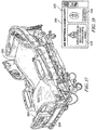
- FIG. 1 An illustrative patient support apparatus embodied as a hospital bed 10 is shown in Fig. 1 .
- the bed 10 is illustrated as a hospital bed; however, it will be appreciated that the bed 10 may be utilized in any healthcare facility or home.
- the bed 10 may be utilized in a nursing home or in a patient own home under hospice care.
- the support surfaces and devices described herein may be equally applicable to other support apparatuses, for example, chairs, wheelchairs, stretchers, etc.
- the bed 10 includes a microclimate system 12 mounted on a frame structure 14 that supports the microclimate system 12 above a floor 11.
- the microclimate system 12 is arranged to underlie a patient supported on the bed 10.
- the microclimate system 12 is configured to cool and dry the interface between a patient and the bed 10 to promote skin health by moving air along the interface when the patient is supported on the bed 10.
- the microclimate system 12 may include an environmental sensor unit configured to detect information about the environment around the microclimate system 12 so that operation of the microclimate system 12 can be adjusted to account for environmental temperature, humidity, and/or pressure.
- the support surface 16 (sometimes called a mattress) is configured to underlie a patient supported on the bed 10.
- An air box (not shown) may be coupled to the support surface 16 to provide conditioned air to the support surface 16 in order to cool and dry the interface between a patient and the support surface 16 when the patient is supported on the bed 10.
- the support surface 16 includes a topper 20 and a lower ticking 22 that cooperate to encase a foam shell 24, a foam head section 26, a foam foot section 28, body bladders 30, and turn bladders 32 as shown, for example, in Fig. 2 .
- the bladders 30 may be passive or active pressure redistribution bladders.
- the bladders 30 may also include heel suspension bladders.
- a heel suspension feature may be utilized to replace foam wedges typically used in healthcare facilities.
- Other embodiments of a heel suspension feature may include a portion of the foot section 28 that folds over.
- a cam may be provided to rotate a portion of the foot section 28 upward for heel suspension. It may be desired that the turn bladders 32 are also configured as passive or active pressure redistribution bladders.
- a passive pressure redistribution system may utilize a series of pressure release valves and foam filled bladders.
- the topper 20 forms a top face 36 of the support surface 16 and is configured to conduct conditioned air provided by the air box 18 along the interface between a patient and the support surface 16 when the patient is supported on the bed 10.
- the foam components 24, 26, 28 and the bladders 30, 32 cooperate to support a patient when the patient is supported on the bed 10.
- the support surface 16 may also include a coverlet 40 encasing the topper 20 and the lower ticking 22 as shown in Fig. 1 .
- the topper 20 illustratively includes a bottom layer 41, a middle layer 42, and a top layer 43 as shown in Fig. 2 .
- the middle layer 42 is illustratively a three-dimensional material that allows conditioned air to flow between the bottom layer 41 and the top layer 43 along the top face 36 of the support surface 16 from a foot end 21 to a head end 31 of the support surface 16.
- the top layer 43 is made from a perforated material that allows moisture from a patient supported on the topper 20 to pass through the top layer 43 and be carried away for evaporation by conditioned air flowing through the middle layer 42 of the topper 20.
- other air-flow cooled toppers may be used with the support surface 16.
- air-loss toppers, air-fluidized bead toppers, and the like can be used in support surface 16.
- an air box or pneumatic blower 50 is illustratively adapted to be mounted on the frame structure 14, but in other embodiments may be integrated into the frame structure 14.
- a cost of the micro-climate system 12 may be reduced if the microclimate system 12 is not needed.
- the external nature of the blower 50 allows additional features to be packaged into the support surface 16, e.g. heel suspension, temperature control, etc.
- the air box 50 is coupled to the support surface 16 to provide air to the support surface 16.
- the air box 18 includes a housing 52 (including air handling unit), a connector hose 54, a power cord 56, and a user interface 58.
- the user interface 58 is coupled to the housing 52 and includes an LCD display 60 and having a number of buttons.
- the user interface is described in more detail below.
- the power cord 56 may be electrically coupled to a source of power, e.g. a wall outlet or a power source incorporated into the bed 10.
- the housing 52 holds an environmental sensor unit and an air handling unit.
- the connector hose 54 extends from the housing 52 to the support surface 16 to couple the air handling unit to the support surface 16.
- the connector hose 54 is illustrated as a single hose 54.
- the connector hose 54 is configured to provide air flow to the microclimate system 12 and the bladders 30, 32.
- the housing 52 may include a valve system to selectively provide air flow to one of the microclimate system 12 or the bladders 30, 32.
- the connector hose 54 may include a plurality of hoses, wherein each hose connects the air handling unit to one of the microclimate system 12, the bladders 30, and the bladders 32.
- An interface 80 is provided on a side of the support surface 16 in a positioned that is not blocked by a siderail of the bed 10. Although the display is illustrated in the side of the support surface 16, the interface 80 may be located at any position along the support surface 16, e.g. at a foot of the support surface 16.
- An expanded view of the interface 80 is provided in Fig. 4 .
- the interface 80 includes a weight based value control system having a dial 82 and a plurality of indicators 84 that may be selected by the dial 82.
- the indicators 84 include three weight ranges; however, any number of weight ranges may be contemplated. The weight ranges are related to a weight of the patient.
- the body bladders 30 are inflated to an appropriate level to provide comfort for the patient.
- first indicator 84a provides a range of 32 kg to 82 kg.
- the body bladders 30 may be inflated to a first firmness.
- a second indicator 84b provides a weight range of 83 kg to 159 kg. Patients in this weight range may require the body bladders 30 to be inflated to a greater level than the first weight range. That is, when selecting the indicator 84b the body bladders 30 are inflated to a firmness that is greater than the firmness when the indicator 84a is selected.
- a third indicator 84c provides a weight range of 159 kg to 226 kg.
- Patients in this weight range may require the body bladders 30 to be inflated to a greater level than the second weight range. That is, when selecting the indicator 84c the body bladders 30 are inflated to a firmness that is greater than the firmness when the indicator 84b is selected.
- a caregiver may select the appropriate weight range (i.e. indicator 84) prior to the patient being positioned on the support surface 16 or while the patient is on the support surface 16.
- the interface 80 also includes an end of life indicator 90.
- the end of life indicator 90 includes a "new" button 92 that may be selected when the support surface 16 is installed at the healthcare facility. By selecting the "new" button 92, an end of life meter for the support surface 16 is activated.
- the end of life indicator 90 also includes a meter 94.
- the meter 94 is a liquid crystal display (LED).
- the meter 94 includes an upper limit 96 and a lower limit 98. When the support surface 16 is first installed and the "new" button 92 is selected, the meter 94 is started at the lower limit 98. As the support surface 16 becomes worn out, the meter 94 raises toward the upper limit 96.
- the meter 94 is displayed in different colors. For example, when the meter 94 is near the lower limit 98, the meter 94 may be green. As the meter 94 raises to a position between the upper limit 96 and the lower limit 98, e.g. half way between the upper limit 96 and the lower limit 98, the meter 94 may turn yellow. As the meter 94 approaches the upper limit 96, the meter 94 may turn red. As the meter 94 approaches the upper limit 96, caregivers are alerted that the support surface 16 may have become worn out.
- the end of life detector includes a timer that is activated when the support surface 16 is installed.
- the timer counts down the life of the support surface 16 over a predetermined time, e.g. 3 years, 5 years, and 7 years.
- a predetermined time e.g. 3 years, 5 years, and 7 years.
- an end of life detector for a support surface 16 with a 7 year life span will indicate that the support surface 16 should be replaced 7 years from the date of installation.
- Some timers may be electronic, whereas other timers may include a chemical that erodes or grows over time. The chemical may be configured to erode entirely from the system within a predetermined time from the date that the chemical is activated.
- the timer may be switched on and off.
- the timer may track an amount of time that the bed is in use by tracking when a patient enters and exits the support surface 16.
- the timer is switch on to track an amount of use.
- the timer is turned off.
- the timer tracks when the support surface 16 has power. For example, when the support surface 16 is plugged in and power is delivered to the support surface 16, the timer switches to an on position to track use. When the support surface 16 is turned off and is not receiving power, the timer switches to an off position and stops tracking the use of the support surface 16 until power is restored.
- Fig. 5 illustrates another embodiment of a support surface 120.
- the support surface 120 is similar to the support surface 16 and includes several elements that are referenced with the same reference number.
- the support surface 120 includes a side 122 having an opening 124.
- a cavity 126 extends from the opening 124 and into the support surface 120.
- the cavity 126 is illustrated in a thigh section 130 of the support surface 120; however, in other embodiments, the cavity 126 may be formed in a head section 132, a seat section 134, or a foot section 136 of the support surface 120.
- the cavity 126 is formed in a section of the support surface 120 where a caregiver will have access to the cavity 126.
- the cavity 126 may be formed in a foot end 140 or a head end 142 of the support surface 120.
- An inlet port 146 (shown in dashed lines) is housed within the cavity 126.
- the inlet port 146 extends from a back wall 148 of the cavity 126.
- the inlet port 146 is in fluid communication with the microclimate system 12. Air flow into the inlet port 146 is delivered to the microclimate system 12.
- the inlet port 146 is also in fluid communication with the bladders 30, 32 so that air flow into the inlet port 146 may be delivered to the bladders 30, 32.
- a valve may be positioned downstream from the inlet port 146 to direct air flow to one of the microclimate system 12, the bladders 30, or the bladders 32.
- the support surface 120 may include a plurality of inlet ports 146, wherein each inlet port 146 is in fluid communication with one of the microclimate system 12, the bladders 30, or the bladders 32.
- An air box or pneumatic blower 150 is configured to be positioned within the cavity 126. By positioning the blower 150 in the cavity 126, space on the footboard of the bed 10 is not required. Additionally, the blower 150 may be added only when needed to save money and resources within the healthcare facility. Moreover, the blower 150 has a smaller more compact size, which saves storage space within the healthcare facility. In some embodiments, the blower 150 may be stored in the patient room. The blower 150 can be positioned within the cavity 126 while a patient is on the support surface 120. The blower 150 includes an outlet port 152. In some embodiments, the blower 150 may include a plurality of outlet ports 152.
- the blower 150 is configured to be inserted into the cavity 126 so that the outlet port 152 fluidly couples to the inlet port 146.
- the plurality of outlet ports 152 fluidly couple to the plurality of inlet ports 146.
- the blower 150 controls airflow from the outlet port 152 into the inlet port 146 and, consequently, into the microclimate system 12, the bladders 30, and the bladders 32.
- the blower 150 may have a valve to control air flow to one of the outlet ports 152, thereby controlling air flow to one of the microclimate system 12, the bladders 30, or the bladders 32.
- the blower 150 When a patient is in need of additional therapy, the blower 150 may be inserted into the cavity 126 to provide air flow to the microclimate system 12, the bladders 30, and the bladders 32.
- the blower 150 is illustrated with a power cord 156 that plugs into a wall socket.
- the blower 150 may be battery operated.
- the blower 150 may electrically couple to the support surface 120 when the blower 150 is inserted into the cavity 126. Such coupling may be achieved with a plug on the blower 150 that engages an outlet in the cavity 126 when the blower 150 is inserted into the cavity 126. If a patient is not in need of therapy, the blower 150 can be removed from the cavity 126.
- the walls of the cavity 126 are formed from a stiff material that maintains a shape of the cavity 126 even if a patient is on the support surface 120. That is, the cavity 126 is left open and does not collapse.
- the cavity 126 may be filled, for example, with a foam block, when the blower 150 is not in use.
- the blower 150 includes an interface 160 that enables a caregiver to control operation of the blower 150.
- An example of an interface for a blower is provided below.
- the support surface 120 also includes an end of life indicator 90 that operates as described above. In some embodiments, operating the blower 150 may affect the life span of the support surface 120. Accordingly, the end of life detector of the end of life indicator 90 may track usage of the blower 150.
- the end of life detector may include a timer that is activated when the blower 150 is installed within the cavity 126. The timer may be stopped when the blower 150 is removed from the cavity 126.
- a patient support surface 200 is provided that is similar to the patient support surface 16. Elements of the patient support surface 200 that are the same as the elements described with respect to patient support surface 16 are referenced using the same reference numbers.
- the patient support surface 200 includes an airbox or pneumatic blower 202 positioned within the patient support surface 200.
- the blower 202 is fluidly coupled to the microclimate system 12 and the bladders 30, 32. As described above valves may be positioned within the blower 202 or the microclimate system 12 to control the flow of air to one of the microclimate system 12, the bladders 30, or the bladders 32.
- the blower 202 is permanently housed in the support surface 200 and configured to be discarded or recycled when the support surface 200 is replaced.
- the blower 202 may be accessible via an opening in the support surface 200 to provide maintenance for the blower 202 and/or to replace the blower 202 if the blower becomes damaged before the end of life of the support surface 200. In some embodiments, when the support surface 200 reaches its end of life, the blower 202 may be removed from the support surface 200 and reused in a new support surface 200.
- the microclimate system 12 becomes available in all support surfaces 200, thereby eliminating the need for a caregiver to find a blower that may be in storage. Additionally, the blowers 202 will not become lost within the healthcare facility, thereby reducing inventory and increasing costs. With the blower 202 built into the support surface 200, patients do not need to wait for a blower 202 to receive therapy. Moreover, an end of life indicator that operates based on usage, e.g. tracks use when the system is powered, will automatically begin tracking usage when the support surface 200 is powered, rather than requiring a blower to be added to the support surface 200.
- the blower 202 also avoids becoming contaminated during use because the blower 202 is incorporated into the support surface 200 and not exposed to the healthcare facility. Further, the blower 202 provides quiet operation since noises from the blower 202 are filtered by the foam and the bladders within the support surface 200.
- an interface 204 may be provided on a side 206 of the support surface 200 to enable a caregiver to control the blower 202.
- Another interface 210 is provided on the side 206 of the support surface 200. Referring to Fig. 7 , the interface 210 includes the dial 82 and the plurality of indicators 84 that may be selected by the dial 82 as described above. The interface 210 is illustrated without an end of life indicator; however, it should be appreciated that the interface 210 may include an end of life indicator as shown in the interface 80 as described above.
- a controller 220 is provided that may be used with any of the support surfaces described herein.
- the controller 220 is configured to control the microclimate system 12.
- the controller 220 is positioned on a power cord 222, e.g. the power cord of any of the blowers described herein or the power cord of any of the support surfaces described herein.
- the controller 220 is configured to be operated by either the caregiver or the patient. That is, the controller 220 may be configured to be within reach of the patient when the patient is supported on a support surface.
- the controller 220 may include a meter 224 that indicates a remaining life span of the support surface 200.
- the meter 224 may include a plurality of LED colored bars 226 indicating the remaining life of the support surface.
- the meter 224 may include eight bars 226 that are all lit green when the support surface 200 has a first predetermined life span remaining. As the life span decreases, fewer bars 226 may be lit. As an example, when only 4-5 bars 226 are lit corresponding to a second predetermined life span remaining that is less than the first predetermined life span, the bars 226 may be lit in yellow. As another example, when only 3 bars 226 or fewer are lit corresponding to a third predetermined life span less than the second predetermined life span, the bars 226 may be illuminated in red. When only one bar 226 is lit, the bar may flash red.
- the controller 220 may include a power switch 228 to turn the microclimate system 12 on and off.
- the power switch may be a push button switch, but may take the form of any switch.
- An intensity button may enable a user to control the intensity of the microclimate system 12. That is, an amount of airflow from the microclimate system 12 may be increased or decreased with the button.
- a meter may be provided to indicate a current intensity of the microclimate system 12. The meter may only be visible when the microclimate system 12 is turned on. Additionally, the meter may include various colors to display the intensity of the microclimate system 12. For example, when the microclimate system 12 is set at a low airflow, the meter may light up 1-5 bars in a green color.
- the meter When the airflow is increased, the meter may light up an additional 1-4 bars in a yellow color. When the airflow is further increased, the meter may light up an additional 1-3 bars in a red color. Accordingly, the intensity of the microclimate system 12 may be indicated both through the number of illuminated bars and the color of the bars. In some embodiments, the meter may only include a number of bars. In some embodiments, the meter may only include colors. In even further embodiments, the meter may have a numerical indicator.
- a support surface 250 is illustrated in Fig. 9 .
- the support surface 250 includes elements that are the same as the elements of the support surface 16 and referenced with the same reference number.
- the support surface 250 is positioned on a frame 252 having a foot end 254.
- An airbox or pneumatic blower 260 is coupled to the foot end 254.
- the blower 260 may be removably coupled to the foot end 254.
- the blower 260 may be coupled to a siderail 256 of the frame 252.
- the blower 260 is fluidly coupled to the microclimate system 12 and the bladders 30, 32 via a hose 262. As set forth above, multiple hoses 262 may couple the blower 260 to the microclimate system 12 and the bladders 30, 32.
- the blower 260 and/or the support surface 250 may include at least one valve to direct air flow from the blower 260 to the microclimate system 12, the bladders 30, or the bladders 32.
- the blower 260 also includes a power cord 264 is illustrated as electrically coupling the blower 260 to a power source on the frame 252. Alternatively, the power cord 264 may be electrically coupled to a wall outlet.
- the blower 260 includes a housing 270.
- the power cord 264 and the hose 262 extend from the housing 270.
- the housing 270 includes an interface 280 that may be used by a caregiver to control the blower 260.
- the caregiver can control air flow to the microclimate system 12, the bladders 30, and the bladders 32.
- the interface 280 may be used with any of the support surfaces described or illustrated herein.
- the interface 280 may be incorporated into any of the blowers and/or any of the support surfaces described or illustrated herein.
- the interface 280 may include a screen 282, e.g. an LED screen.
- the screen 282 is a touch screen that enables the caregiver to select from various operational settings.
- the screen 282 includes a button 284 to control a pressure of the body bladders 30.
- the button 284 enables alternating pressure within the body bladders 30. That is, the blower 260 alternates inflating and deflating the body bladders 30 to increase and decrease an air pressure within the body bladders 30, thereby increasing and decreasing a firmness of the support surface 250. By alternating the pressure within the body bladders 30 a likelihood of the patient acquiring pressure ulcers may be reduced.
- the blower 260 gradually increases the pressure of the body bladders 30 and then gradually decreases the pressure of the body bladders 30. In other embodiments, the increase and decrease in pressure may occur more rapidly to provide pulses to the patient. In some embodiments, all of the body bladders 30 are inflated and deflated simultaneously, whereas in other embodiments, some body bladders 30 are inflated while others are deflated to rotate the patient.
- the button 284 may open a second screen that enables the caregiver to select specific pressure levels and/or otherwise control the pressure within the body bladders 30.
- a button 286 is provided to control the microclimate system 12.
- the button 286 may turn the microclimate system 12 on and off.
- the button 286 may open a microclimate screen that enables the caregiver to select an amount of airflow through the microclimate system 12.
- the blower 260 is activated to discharge airflow to the microclimate system 12 to prevent dry skin in injury prone areas of the patient, e.g. areas that may develop pressure ulcers.
- a button 288 activates a max inflate operation of the support surface 250.
- all of the body bladders 30 are inflated to a maximum capacity.
- the bladders 32 may also be inflated to a maximum capacity.
- the support surface 250 is at a maximum firmness which assists the caregiver in repositioning the bed.
- a button 290 enables a comfort adjustment operation of the support surface 250. Activating the button 290 may activate a comfort screen that enables the caregiver to selectively inflate and deflate the body bladders 30.
- the body bladders 30 may be adjusted per zones of the support surface 250. That is a head section, a torso section, a seat section, and a foot section of the support surface 250 may be individually controlled to inflate or deflate each section to a different pressure. For example, for patient comfort, the head section of the support surface 250 may be inflated while deflating the seat section, thereby raising the patient's head. Likewise, the foot section may be inflated to a greater capacity than the seat section to raise the patient's feet.
- the bladders 32 may also be inflated or deflated to turn the patient onto one side.
- a CPR button 292 activates a CPR function of the support surface 250. Like button 288, the CPR button 292 inflates all of the bladders 30 to a maximum pressure. However, the CPR button 292 also stops all other therapies currently active in the support surface 250, for example, the microclimate system 12, heaters, and any therapy that may vibrate or pulse the support surface 250. By inflating the bladders 30 to a maximum pressure, the support surface 250 is at a maximum firmness, which is ideal for performing CPR on a patient.
- Part of the screen 282 also includes an on button 300 and an off button 302 for a patient pendant (described in more detail below).
- the on button 300 When the on button 300 is selected, the patient pendant enables the patient to individually control various comfort features of the support surface.
- the off button 302 When the off button 302 is selected, the patient pendant is disabled and the patient is not capable of controlling any support surface functions.
- a home button 304 returns the interface 280 to the screen 282 if the interface has been changed to a different screen as described above.
- An alarm button 306 alerts other caregivers, for example, at the nurse's station, of emergencies. Such emergencies may include a patient who is coding, a patient who is having a severe reaction to medication or the like, a patient who has become ill, a patient who has become violent, etc.
- a settings button 308 activates a settings screen that enables the caregiver to alter various settings of the interface 280, the support surface 250, or any other device coupled to the support surface 250.
- An exemplary patient pendant 320 is illustrated in Fig. 11 and includes support surface firmness controls 322.
- the firmness controls 322 control an amount of pressure in the body bladders 30 by inflating or deflating the body bladders 30.
- a button 324 is provided to increase a pressure of the body bladders 30 by supplying additional air flow to the body bladders 30 from the blower 260.
- Another button 326 is provided to decrease a pressure of the body bladders 30 by releasing air from the body bladders 30.
- the button 324 is includes a plus sign and the button 326 includes a minus sign.
- a meter 328 displays the current firmness of the support surface 250.
- the meter 328 includes a plurality of bars 330 that are lit, e.g. with LEDs, to display the current firmness.
- the support surface 250 is at a lowest level of firmness. As the button 324 is activated, the number of lit bars 330 increases corresponding to the amount of pressure increase. If all of the bars 330 are lit, the support surface 250 is at a maximum firmness. As the button 326 is activated, fewer bars 330 remain lit to correspond to a decrease in pressure.
- the pendant 320 also includes an alternating pressure control 340.
- the alternating pressure control 340 controls alternations in pressure within the body bladders 30 as related to the alternating pressure function described above.
- the alternating pressure control 340 may control a rate at which the body bladders 30 alternate in pressure.
- the alternating pressure control 340 may also control a variance in pressures between max inflate and max deflate.
- a minimum setting, a normal setting, or a maximum setting may be selected.
- the selected setting is indicated by one of three lights (LEDs) 342 provided next to the alternating pressure control 340.
- a light 342a indicates the minimum setting
- a light 342b indicates the normal setting
- a light 342c indicates the maximum setting.
- the maximum setting alternates between inflated and deflated faster than the normal setting, which, in turn, alternates between inflated and deflated faster than the minimum setting. In some embodiments, the maximum setting inflates and deflates over a greater pressure range than the normal setting, which inflates and deflates over a greater pressure range than the minimum setting.
- a sleep mode button 350 positions the support surface 250 for a comfortable sleeping position.
- the sleep mode button 350 may inflate and deflate certain body bladders 30 to comfortably position the patient for sleeping.
- the sleep settings are patient specific and programmed at the time the patient is admitted pursuant to the patient's requests.
- the sleep mode button 350 may also raise and lower parts of the bed, e.g. the head section or the foot section.
- a massage control 372 includes an activation button 374. Selecting the activation button 374 cycles the massage control 372 between vibrations, pulses, and off. For example, pressing the button 374 a first time activates vibration mode, wherein the body bladders 30 are vibrated with rapid air flow. The vibration mode is indicated with an indicator 378 that is lit when the vibration mode is selected. Pressing the button 374 a second time activates the pulsation mode, wherein air flow is pulsed through the body bladders 30. The pulsation mode is indicated with an indicator 380 that is lit when the pulsation mode is selected.
- the intensity of the massage control may be altered with an increase button 382 and a decrease button 384, wherein the increase button 382 increases a rate of vibration or pulses, and the decrease button 384 decreases the rate of vibrations pulses.
- An LED meter 386 indicates a level of intensity between maximum intensity 388 and minimum intensity 390.
- a microclimate control 400 toggles the microclimate system 12 between various intensities.
- the microclimate control 400 is only activated when a caregiver activates the microclimate system 12, e.g. from the interface 280 as described above.
- the patient may activate the microclimate system 12 with the microclimate control 400. That is, activating the microclimate control 400 may activate the microclimate system 12 and then allow the patient to toggle through the intensity levels before the microclimate system 12 is deactivated after the patient has toggled through each intensity level. For example, pressing the microclimate control 400 a first time, places the microclimate system 12 at a minimum intensity, as indicated by light 402, wherein the microclimate system 12 provides a low level of air flow to the patient.
- Pressing the microclimate control 400 a second time places the microclimate system 12 into normal operation, as indicated by light 404. Pressing the microclimate control 400 a third time places the microclimate system 12 at a maximum intensity, as indicated by light 406, and wherein a maximum amount of air flow is provided to the microclimate system 12. In an embodiment where a caregiver must activate the microclimate system 12, pressing the microclimate control a fourth time returns the microclimate system 12 to the minimum intensity. In another embodiment, pressing the microclimate control 400 a fourth time may deactivate the microclimate system 12.
- a foot warming button 410 activates a foot warmer 412 within the support surface 250.
- the foot warmer 412 is illustrated in Fig. 9 as being incorporated into the support surface 250.
- the foot warmer 412 may be an additional component that is positioned on the support surface 250.
- the support surface 250 includes other warmers, for example, a seat warmer and/or a back warmer. Any warmers incorporated into the support surface 250 may be controlled by a patient pendant, e.g. pendant 370.
- An indicator 414 is lit when the foot warmer is activated.
- an intensity of heat from the foot warmer from a low heat to a high heat may be controlled with the pendant 370.
- a compression sleeve 450 is coupled to the blower 260 via a hose 452.
- the compression sleeve 450 is illustrated on the patient's legs to prevent blood clots and/or pressure ulcer in the patient's legs.
- the compression sleeve 450 includes a right sleeve 454 and a left sleeve 456.
- an icon or button 460 appears on the interface 280, as illustrated in Fig. 14 . Selecting the icon 460 activates compression screen 462 on the interface 280.
- the screen 462 illustrates the right sleeve 454 and the left sleeve 456.
- each sleeve 454 and 456 includes several zones 470, for example, an upper leg zone 472, a first lower leg zone 474, a second lower leg zone 476, and a calf zone 478.
- each zone 470 may be supplied with the same pressure. In other embodiments, the zones 470 may each be supplied with a different pressure depending on the needs of the patient.
- a weigh scale 500 is incorporated into the support surface 250.
- the weigh scale 500 may be positioned within the support surface 250.
- the weigh scale 500 may be positioned under the support surface 250.
- the weigh scale 500 includes load cells 502 that monitor a weight of a patient on the support surface 250.
- the load cells 502 are electrically coupled to a transmitter 504.
- the transmitter 504 is wirelessly connected to the interface 280.
- the transmitter 504 sends signals to the interface 280 indicative of a weight measured by the load cells 502.
- the transmitter 504 may include a radio-frequency identification tag to identify the support surface 250 at a remote location or at the interface 280.
- the transmitter 504 may communicate with a cloud server via wireless connections, Bluetooth® connections or other wireless capabilities.
- the interface 280 includes a screen 506 that enables an operator to control the weigh scale 500.
- An icon 510 allows the caregiver to wirelessly connect the interface 280 to the weigh scale 500 so that the interface 280 may receive signals from the weigh scale 500.
- An icon 512 syncs the interface to the weigh scale 500 to receive a signal from the transmitter 504 indicative of the patient's weight.
- the screen 506 displays the patient's weight when the signal is received from the transmitter 504.
- the screen 506 also displays a date and time that the signal was received.
- some end of life indicators may track the use of a support surface, e.g. support surface 250, based on an amount of time that the support surface 250 is in use.
- the weigh scale 500 may detect that a patient is on the support surface 250. The weigh scale 500 then sends a signal to the end of life indicator instructing the end of life indicator to begin tracking time with a timer. When the weigh scale 500 detects that the patient is no longer on the support surface 250, the weigh scale 500 sends a signal to the end of life indicator instructing the end of life indicator to stop the timer.
- the life span of the support surface may be three years.
- the end of life indicator reduces remaining life span of the support surface 250 by 2 hours. That is, by communicating with the weigh scale 500, the end of life indicator tracks an actual usage of the support surface 250 and alerts the caregiver when the usage reaches a predetermined time.
- the end of life indicator may also factor the weight of a patient in determining a remaining useful life of the support surface 250. For example, the support surface 250 may have a useful life of 7 years for patients under 200 pounds, and a useful life of only 5 years for patients over 200 pounds. By receiving a signal indicative of the patient's weight, the end of life indicator may more accurately determine the remaining life span of the support surface 250.
- the weigh scale 500 provides bed entry and bed exit features that may be utilized in conjunction with caregiver input to track a use of the support surface 250.
- a bed entry signal from the weigh scale triggers a continuous timer that is started and runs as long as the patient is on the support surface 250. The timer pauses when a bed exit signal is delivered from the weigh scale 500.
- the weigh scale 500 also determines the weight of the patient. In other embodiments, the patient weight may be entered by the caregiver.
- Each block of support surface occupancy is recorded along with the patient's weight to provide a usage profile.
- the usage profile provides the healthcare facility with real-world use data that may be used to determine surface performance trends in the support surface over time.
- a transmitter 520 is positioned with the support surface 250.
- the transmitter 520 may be a near field communication device or any other transmitter capable of wirelessly communicating with the interface 280. In some embodiments, the transmitter 520 may also communicate with a remote hub, for example, a nurse's station.
- the transmitter 520 is electrically coupled to an end of life indicator incorporated with the support surface 250. As described herein, the end of life end indicator may be the weigh scale 500 described in Fig. 15 , an electrical timer and/or a chemical timer. In some embodiments, the electrical and/or chemical timer may count down a useful life of the support surface 250. In other embodiments, the electrical timer may track an amount of time that a patient is on the support surface 250. In yet another embodiment, the electrical timer may track an amount of time that the support surface 250 is receiving power from a power supply or an amount of time that the support surface 250 is turned on.
- the transmitter 520 is configured to communicate with the end of life indicator to receive a signal indicative of a remaining useful life of the support surface 250.
- the transmitter 520 is further configured to wirelessly communicate with the interface 280 to display an alert regarding the remaining useful life of the support surface 250.
- the transmitter 520 may include a radio-frequency identification tag to identify the support surface 250 at a remote location or at the interface 280.
- the transmitter 520 may communicate with a cloud server via wireless connections, Bluetooth® connections or other wireless capabilities.
- the interface 280 may have a screen 522 as illustrated in Fig. 18 .
- the screen 522 includes a wireless connection button 524 that may be activated to communicatively couple the interface 280 to the transmitter 520.
- the button 524 may be activated so that the interface 280 begins receiving a wireless signal from the transmitter 520.
- the interface 280 is in constant communication with the transmitter 520 while both the interface 280 and the transmitter 520 are powered.
- the screen 522 displays an icon 526 indicating the remaining life of the support surface 250 as determined from the signal from the transmitter 520.
- Fig. 18 illustrates a warning that the support surface 250 is approaching an end of its useful life.
- This warning may be displayed when the support surface 250 has a predetermined remaining useful life, e.g. 1 year, 6 months, etc.
- the icon 526 may display an estimated remaining life in a numerical value.
- the icon 526 may display the words "7 years, "5 years,” “6 months,” etc.
- the icon 526 may display a color indicative of the remaining life.
- the color green may indicated that the support surface 250 has over 5 years of remaining useful life
- the color yellow may indicate that the support surface 250 has between 1 year and 5 years of remaining useful life
- the color red may indicate that the support surface 250 has less than 1 year of remaining useful life.
- numerical figures may be used in conjunction with colors.
- the icon 526 may display a meter indicative of the remaining useful life of the support surface 250. The meter may be used in conjunction with numerical figures and/or colors.
- the screen 522 may display a predicted age of the support surface 250 based on usage, an actual age of the support surface 250, a manufacturing date, an installation date, fault codes, error messages, and/or usage data, e.g. number of uses, average patient weight, mean patient weight, average time of use, and/or mean time of use.
- a serial number of the support surface 250 is recorded at a time of manufacture. This number is then stored and made available to the healthcare facility so that the healthcare facility can track a usage of the support surface 250.
- a continuous timer tracks the time that the support surface 250 is in use.
- the timer stops and records a total usage time. The total usage time is associated with the serial number and data related to the total usage is transmitted to a remote hub of the healthcare facility allowing the usage data of all support surfaces 250 to be associated with the serial number of the support surface 250 and recorded by the healthcare facility.
- an end of life indicator 540 is incorporated into a top face 542 of the support surface 250.
- the end of life indicator 540 is configured to change a color of the top face 542 to indicate a remaining useful life of the support surface 250.
- the top face 542 may be blue.
- the top face 542 may alter to a light blue color indicating caution.
- the top face 542 may turn to a grey color. In some embodiments, other colors such as green, yellow, and red may be provided.
- the top face 542 remains blue when it has over a first predetermined remaining useful life, e.g. over 5 years.
- the top face 542 may turn light blue when the remaining useful life is between the first predetermined remaining useful life and a second predetermined remaining useful life, e.g. 1-5 years.
- the top face 542 may turn grey when the remaining useful life is below the second predetermined remaining useful life, e.g. less than 1 year.
- the top face 542 is filled with a base chemical that changes color when exposed to a catalyst.
- a seal is broken to release the catalyst into the top face 542, thereby mixing the catalyst with the base chemical.
- the base chemical changes colors over time.
- the base chemical may be configured to fully change colors over the span of 7 years.
- the chemical may change colors over a different time span, e.g. 5 years, thereby altering the time span over which the remaining life of the support surface 250 is indicated.
- the chemical may be selected based on an expected life span of the support surface 205. For example, if the expected life span of the support surface 250 is 5 years, a chemical that changes colors over 5 years may be selected.
- the chemical erodes over time. In some embodiments, the chemical grows over time.
- the top face 542 includes a thin filament, for example, liquid crystals, that may be controlled to display various colors.
- the support surface 250 may include a weigh scale and/or electrical timer, as described above. Based on signals from the weigh scale and/or electrical timer, filament may be altered in color to indicate the remaining life span of the support surface. As set forth above, such a display may include a green, yellow, red color scheme. It should be appreciated that any color scheme may be utilized.
- the support surface 250 include an end of life indicator 270 on a side 272 of the support surface 250 as illustrated in Fig. 20 .
- the end of life indicator 270 is positioned on the side 272 of the support surface 250 so that the end of life indicator 270 is not obstructed by the siderail 256.
- the end of life indicator 270 is positioned such that the end of life indicator 270 is visible to a caregiver.
- the end of life indicator 270 includes a meter 274.
- the meter 274 may be chemically actuated as described above. In some embodiments, the meter 274 may be electrically actuated by LEDs or the like and display an input from a weigh scale or electrical timer.
- the meter 274 includes a series of marks 276 illustrated as 5 years, 4 years, 3 years, 2 years, and 1 year. It should be appreciated that the meter 274 may display other time spans. As the remaining life of the support surface 250 decreases a colored bar 278 of the meter 274 drops. That is the colored bar 278 starts at the 5 year mark 276 and after 1 year of use, the colored bar drops to the 4 year mark 276, etc. Throughout the life of the support surface 250 the colored bar 278 continues to drop corresponding to an elapsed time until the colored bar 278 is extinguished at 0 years indicating that the support surface 250 should be replaced. In some embodiments, the colored bar 278 may also change colors. For example, at the 5 year mark 276, the colored bar 278 may be green; at the 3 year mark 276, the colored bar 278 may be yellow; and at the 1 year mark 276, the colored bar 278 may be red.
- a support surface 600 includes a head end 602, an opposite foot end 604, a right side 606, and a left side 608.
- An x-ray cassette sleeve 620 is positioned within the support surface 600 and configured to retain an x-ray cassette 622.
- the sleeve 620 is sealed with zipper 624.
- a fastening mechanism other than zipper 624 may be utilized, e.g. hook and loop fasteners, etc.
- the zipper 624 extends along the entire length 626 of the head end 602.
- the zipper 624 also extends partially along a length 628 of the right side 606 and partially along the length 628 of the left side 608.
- the support surface 600 includes an upper ticking 640 that is sealed to a lower ticking 642 with a zipper 644.
- the zipper 644 may be actuated to separate the upper ticking 640 from the lower ticking 642 to expose an inside of the support surface 600, for example, bladders and other components described above.
- the zipper 624 is positioned between the upper ticking 640 and the zipper 644.
- the zipper 624 has a different color than the zipper 644 to distinguish the sleeve 620 from the ticking connection.
- the zipper 624 and the zipper 644 may have different sizes to distinguish the zippers 624, 644.
- Figs. 24 and 25 illustrate the sleeve 620 in an open configuration that enables insertion and removal of the cassette 622.
- the sleeve 620 includes an opening 650 that is sealed by the zipper 624.
- a cavity 652 extends from the opening 650 into the support surface 600.
- the cavity 652 is configured to receive the cassette 622.
- the opening 650 extends partially along both sides 606, 608 of the support surface 600 and entirely along the head end 602 of the support surface 600 to provide access to the sleeve 620 by a caregiver.
- the caregiver may insert and remove the cassette 622 from the sleeve 620 while a patient is positioned on the support surface 600.
- the sleeve 620 includes an inner liner 660 that is bonded or welded to a rip stop material 662 of the zipper 624 to seal the sleeve 620.
- the liner 660 is welded with ultrasonic welding or radio-frequency welding.
- the liner 660 is formed from a water resistant material, e.g. thermoplastic.
- the sleeve 620 is able to open on three sides to allow for wiping down the sleeve 620 without having to remove the support surface 600 from service. Caregivers can access the sleeve 620 from either the right side 606, the left side 608, or the head end 602. Additionally, the sleeve 620 is larger than conventional sleeves allowing coverage from the head to the seat/hip of the patient allowing for chest, abdominal, and hip x-rays. In some embodiments, the sleeve 620 may extend all the way to the foot end 604 of the support surface 600.
- the sleeve 620 is placed above a core of the support surface 600, the sleeve 620 does not interfere with a microclimate system that may be incorporated into the support surface 600.
- the two separate compartments (the sleeve 620 and the core) of the support surface 600 enable each compartment to accept a fully enclosed fire sock, thereby enabling the support surface 600 to pass a flame test.
- the sleeve 620 can be installed in a support surface 600 with or without a topper.
- a support surface 700 includes a touch sensor 716 coupled to an electronic controller 704.
- a base foam 710 is provided and a plurality of air bladders 712 are positioned above the base foam 710.
- An upper ticking 714 of the support surface 700 extends across the air bladders 712. The patient is configured to lie on the upper ticking 714.
- a capacitive touch sensor 716 is positioned between the base foam 710 and the air bladders 712.
- a touch sensor 716 can be used to detect when a patient is within approximately an inch of the touch sensor 716.
- the touch sensor 716 is a capacitive charge sensor that acts as a switch sending out a signal when it is touched or the human body is within an inch of the touch sensor 716.
- the touch sensor can detect through plastic, glass, paper, or fabric.
- the touch sensor 716 is therefore capable of detecting through air, bladders, and ticking material. Conductive materials can also be attached to the sensor to increase the sensing area.
- the touch sensor 716 can be positioned only under the entire area of the support surface 700 or regionalized where the patient is likely to bottom out.
- the touch sensor 716 When the patient is not within one inch of the touch sensor 716, the touch sensor delivers a first voltage to the electronic controller 704. As illustrated in Fig. 28 , a weight of the patient has caused the air bladders 712 to deform and bottom out. The patient's sacrum 718 is illustrated within one inch of the touch sensor 716. Accordingly, the touch sensor 716 sends a second voltage, e.g. 5V, to the electronic controller 704. Upon receiving the second voltage, the electronic controller 704 sends an audible or visual alert to the caregiver indicating that the patient has bottomed out.
- a second voltage e.g. 5V
- the touch sensor 716 may monitor the patient to determine whether the patient has bottomed out, e.g. come in contact with or close to the base foam 710.
- the touch sensor 716 enables the caregiver to do a "hand check" without actually having to position their hand under the patient. This enables better comfort for the patient, who does not require unnecessary prodding by the caregiver.
- the caregiver is alerted either audibly or visually if the patient has bottomed out.
- Figs. 29 illustrates a conductive fabric 720 that is configured to be used with the touch sensor 716.
- the support surface 700 includes the fabric 720 and the touch sensor 716.
- the fabric 720 is positioned below an upper ticking 730 of the support surface 700.
- a spacer 732 is positioned between the upper ticking 730 and the fabric 720 to isolate the patient from the fabric 720.
- the air bladders 712 are positioned between the touch sensor 716 and the fabric 720.
- the touch sensor 716 is positioned over the base foam 710. As a load 734 is applied to the support surface 700, the fabric 720 is moved closed to the touch sensor 716.
- the fabric 720 is configured to activate the touch sensor 716 when the fabric 720 is within 0.5 inches of the touch sensor 716.
- the touch sensor 716 sends a voltage to the electronic controller 704 indicating that the support surface 700 has bottomed out.
- the support surface 700 may make pressure adjustments with the bladders 712 to raise the patient from the base foam. Additionally, surface bladder pressures may be optimized for an ideal interface pressure without risking bottoming out by understanding the amount of weight that the support surface 700 can withstand. If the bottoming out condition cannot be corrected by adjusting the pressure of the bladders 712, an alarm may be sent to the caregiver or nurse's station. Further, repeatedly bottoming out may be an indicator that the support surface 700 has become worn. As such the touch sensor 716 may aid in determining an end of life of the support surface 700.
- Figs. 31-33 illustrate another sensor 750 for determining bottoming out of a support surface.
- the sensor 750 is positioned within a gap 752 formed in a foam surface 754, e.g. a foam support surface.
- the gap 752 is formed in approximately the bottom inch of the foam surface 754. If the bottom inch of the foam surface 754 collapses, the patient would be determined as having bottomed out.
- the sensor 750 may include a pair of resilient metal conductors 756 and 758 positioned on a top 760 of the gap 752 and a bottom 762 of the gap 752, respectively.
- the conductors 756, 758 may be spaced from one another by means of insulators. The conductors are adapted to contact one another when at least a portion of the patient's bottoms out.
- the sensor 750 may also include a waterproof flexible housing which encloses the conductors 756, 758. It will be readily understood that, when the patient lies on the bed, the sensor 750 will be compressed. The compression of the sensor 750 may result in contact at one or more places between the conductors 756, 758 resulting in an electrical indication that the patient has bottomed out. Fig.
- FIG. 31 illustrates the gap 752 in an expanded configuration.
- the gap 752 is shown as beginning to collapse.
- the gap 752 is entirely collapsed.
- the conductors 756, 758 approach one another, thereby generating the electrical signal.
- the signal increases as the conductors 756, 758 get closer to one another.
- the foam surface 754 is considered to have bottomed out.
- the caregiver is alerted that the patient has bottomed out. Bottoming out may also indicate that the foam surface 754 has reached its end of life.
- FIGs. 34-60 provide support surfaces having a heel suspension mechanism built into the support surface. In such embodiments, caregivers do not have to locate and place a separate heel wedge for the support surface.
- the heel suspension mechanisms described herein eliminate the need to create an improvised solution for heel suspension if a wedge cannot be located.
- the mechanisms also eliminate time spent searching for missing components and allows for more focus on patient care.
- the heel suspension mechanisms described herein can be optimized to work properly with any support surface that is integrated with. For example, the heel suspension mechanisms described herein may be utilized with any of the support surfaces described herein. The mechanisms improve cleaning of the support surface because the mechanisms may be fully integrated inside a support surface cover. Additionally, the mechanisms eliminate the cost of replacing lost heel wedges.
- a patient support surface 800 includes a body 802 having a body section 804 and an opposite foot section 806.
- the patient support surface 800 may be a foam mattress or an air mattress. In some embodiments, the patient support surface 800 may be any of the support surfaces described in Figs. 1-33 .
- a top face 808 extends from the body section 804 to the foot section 806. The top face 808 is positioned at a first height 810 from a bottom 812 of the support surface 800.
- a patient 820 is configured to rest on the top face 808 with their feet 822 at the foot section 806 of the support surface 800.
- a heel suspension mechanism 824 is positioned within the foot section 806 to alter a height of the top face 808. By altering a height of the top face 808, heels 826 of the patient's feet 822 are separated from the top face 808 by a gap 828 (shown in Fig. 35 ).
- the heel suspension mechanism 824 includes a plate 838 having a plurality of grooves 840 formed therein. It should be noted that only one side of the support surface 800 is illustrated; however, it will be appreciated that the support surface 800 may include a plate 838 on both sides of the support surface 800. Optionally, multiple plates 838 may be positioned between the sides of the support surface 800. In the illustrated embodiment, the plate 838 includes three grooves 840a-840c; however, any number of grooves 840 may be contemplated. Each groove 840a-840c is positioned under one of three corresponding sections 842a-842c of the foot section 806. A flexible membrane 844 is coupled to the body 802 and extends along each section 842.
- a cam assembly 846 is configured to position within one of the grooves 840a-840c.
- the cam assembly 846 is further configured to be movable to and from any of the grooves 840a-840c so that the cam assembly 846 is positionable under a corresponding section 842a-842c of the foot section 806.
- the cam assembly 846 includes a rod 848 that is moveable to any of the grooves 840a-840c and sits within the respective groove 840a-840c.
- a cam 850 having a fixed end 852 and a moving end 854 is coupled to the rod 848. It should be noted that, while only a single cam 850 is illustrated, multiple cams 850 may be positioned along the rod 848 between the sides of the support surface 800.
- a handle 856 extends from the rod 848.
- the handle 856 is configured to be rotated so that the moving end 854 of the cam 850 rotates around the fixed end 852 from a first position 860 (shown in Fig. 34 ) to a second position 862 (shown in Fig. 35 ).
- the membrane 844 rests on the fixed end 852 of the cam 850 so that the top face 808 of the foot section 806 is retained at the first height 810.
- the moving end 854 of the cam 850 moves the membrane 844 upward so that the top face 808 of the foot section 806 is raised to a second height 870 from the bottom 812 of the support surface 800, wherein the second height 870 is greater than the first height 810.
- the cam assembly 846 is illustrated in the groove 840b, thereby raising section 842b. It will be appreciated that the cam assembly 846 is also movable to grooves 840a and 840c to raise the height of the section 842a or 842c, respectively.
- a patient support surface 900 includes a body 902 having a body section 904 and an opposite foot section 906.
- the patient support surface 900 may be a foam mattress or an air mattress. In some embodiments, the patient support surface 900 may be any of the support surfaces described in Figs. 1-33 .
- a top face 908 extends from the body section 904 to the foot section 906. The top face 908 is positioned at a first height 910 from a bottom 912 of the support surface 900.
- a patient 920 is configured to rest on the top face 908 with their feet 922 at the foot section 906 of the support surface 900.
- a heel suspension mechanism 924 is positioned within the foot section 906 to alter a height of the top face 908. By altering a height of the top face 908, heels 926 of the patient's feet 922 are separated from the top face 908 by a gap 928 (shown in Fig. 37 ).
- the heel suspension mechanism 924 includes a plurality of cams 940.
- the heel suspension mechanism 924 includes three cams 940a-940c; however, any number of cams 940 may be contemplated.
- Each cam 940a-940c is positioned under one of three corresponding sections 942a-942c of the foot section 906.
- a flexible membrane 944 is coupled to the body 902 and extends along each section 942a-942c.
- Each cam 940a-940c has a fixed end 952 and a moving end 954. It should be noted that, while only a single cam 940a-940c is illustrated, multiple cams 940a-940c may be positioned between the sides of the support surface 800 and coupled via a rod.
- a knob 956 is positioned on each cam 940a-940c to rotate the respective cam 940a-940c so that the moving end 954 of the respective cam 940a-940c rotates around the fixed end 952 from a first position 960 (shown in Fig. 36 ) to a second position 962 (shown in Fig. 37 ).
- each cam 940a-940c when each cam 940a-940c is in the first position 962, the membrane 944 rests on the fixed end 952 of the each cam 940a-940c so that the top face 908 of the foot section 906 is retained at the first height 910.
- the moving end 954 of the cam 940b moves the membrane 944 upward so that the top face 908 of the foot section 906 is raised to a second height 970 from the bottom 912 of the support surface 900, wherein the second height 970 is greater than the first height 910.
- the cam 940b is illustrated as being rotated, thereby raising section 942b.
- cams 940a-940c are also rotatable to raise the height of the section 942a or 942c, respectively. In some embodiments, any number of cams 940a-940c may be rotated to alter the height of the top face 908 of the foot section 906.
- a patient support surface 1000 includes a body 1002 having a body section 1004 and an opposite foot section 1006.
- the patient support surface 1000 may be a foam mattress or an air mattress. In some embodiments, the patient support surface 1000 may be any of the support surfaces described in Figs. 1-33 .
- a top face 1008 extends from the body section 1004 to the foot section 1006. The top face 1008 is positioned at a first height 1010 from a bottom 1012 of the support surface 1000.
- a patient 1020 is configured to rest on the top face 1008 with their feet 1022 at the foot section 1006 of the support surface 1000.
- a heel suspension mechanism 1024 is positioned within the foot section 1006 to alter a height of the top face 1008. By altering a height of the top face 1008, heels 1026 of the patient's feet 1022 are separated from the top face 1008 by a gap 1028 (shown in Fig. 39 ).
- the heel suspension mechanism 1024 includes a plurality of cams 1040.
- the heel suspension mechanism 1024 includes three cams 1040a-1040c; however, any number of cams 1040 may be contemplated.
- Each cam 1040a-1040c is positioned under one of three corresponding sections 1042a-1042c of the foot section 1006.
- Flexible membranes 1044a-1044c are coupled to the body 1002 by a hinge 1046.
- Each membrane 1044a-1044c extends along a respective section 1042a-1042c.
- Each cam 1040a-1040c has a fixed end 1052 and a moving end 1054.
- cam 1040a-1040c may be positioned between the sides of the support surface 1000 and coupled via a rod.
- a knob 1056 is positioned on each cam 1040a-1040c to rotate the respective cam 1040a-1040c so that the moving end 1054 of the respective cam 1040a-1040c rotates around the fixed end 1052 from a first position 1060 (shown in Fig. 38 ) to a second position 1062 (shown in Fig. 39 ).
- each membrane 1044 rests on the fixed end 1052 of the respective cam 1040a-1040c so that the top face 1008 of the foot section 1006 is retained at the first height 1010.
- the moving end 1054 of the cam 1040b rotates the membrane 1044b upward about its hinge 1046 so that the top face 1008 of the foot section 1006 is raised to a second height 1070 from the bottom 1012 of the support surface 1000, wherein the second height 1070 is greater than the first height 1010.
- cam 1040b is illustrated as being rotated, thereby raising section 1042b. It will be appreciated that the cams 1040a-1040c are also rotatable to raise the height of the section 1042a or 1042c, respectively. In some embodiments, any number of cams 1040a-1040c may be rotated to alter the height of the top face 1008 of the foot section 1006.
- a patient support surface 1100 includes a body 1102 having a body section 1104 and an opposite foot section 1106.
- a plurality of foam segments 1108 are positioned within the body 1102 from the body section 1104 to the foot section 1106.
- the support surface 1100 may be any one of the support surfaces described in Figs. 1-33 .
- a top face 1110 extends from the body section 1104 to the foot section 1106. The top face 1110 is positioned at a first height 1112 from a bottom 1114 of the support surface 1100.
- a patient 1120 is configured to rest on the top face 1110 with their feet 1122 at the foot section 1106 of the support surface 1100.
- a heel suspension mechanism 1124 is positioned within the foot section 1106 to alter a height of the top face 1110. By altering a height of the top face 1110, heels 1126 of the patient's feet 1122 are separated from the top face 1110 by a gap 1128 (shown in Fig. 41 ).
- the heel suspension mechanism 1124 includes a plurality of the air bladders 1128 positioned in the foot section 1106 of the support surface 1100 below foam sections 1108.
- the heel suspension mechanism 1124 includes air bladders 1128a-1128d; however, any number of air bladders 1128 may be incorporated into the heel suspension mechanism 1124.
- the bladders 1128 that are not incorporated into the heel suspension mechanism 1124 may be foamed filled air bladders.
- Each air bladder 1128a-1128d is positioned under a respective section 1130a-1130d of the foot section 1106.
- Each bladder 1128a-1128d is fluidly coupled to a valve 1140 via a respective hose 1142a-1142d.
- a hand pump 1144 is fluidly coupled to the valve 1140 to supply air flow to the valve 1140.
- an electrical pump may be fluidly coupled to the valve 1140.
- the valve 1140 includes a dial 1146 that is actuated to direct the air flow to one of the air bladders 1128a-1128d.
- the dial 1146 includes indicators 1148a-1148d that each corresponds to one of the hoses 1142a-1142d and, consequently, the respective bladder 1128a-1128d.
- the hand pump 1144 is operable to supply air flow to one of the bladders 1128a-1128d via the valve 1140 to inflate the respective bladder 1128a-1128d from a first position 1160 (shown in Fig. 40 ) to a second position 1162 (shown in Fig. 41 ).
- each air bladder 1128a-1128d when each air bladder 1128a-1128d is in the first position 1160 the top face 1110 of the foot section 1106 is retained at the first height 1112.
- the air bladder 1128b when the air bladder 1128b is inflated to the second position 1162, the top face 1110 of the foot section 1106 is raised to a second height 1170 from the bottom 1114 of the support surface 1100, wherein the second height 1170 is greater than the first height 1112.
- the air bladder 1128b is illustrated as being inflated, thereby raising section 1130b.
- the air bladders 1128a, 1128c, and 1128d are also inflatable to raise the height of the section 1130a, 1130c, and 1130d, respectively.
- the valve 1140 may be configured so the multiple combinations of air bladders 1128a-1128d may be inflated to alter the height of the top face 1110 of the foot section 1106.
- a patient support surface 1200 includes a body 1202 having a body section 1204 and an opposite foot section 1206.
- a plurality of air bladders 1208 are positioned within the body 1202 from the body section 1204 to the foot section 1206.
- the support surface 1200 may be any one of the support surfaces described in Figs. 1-33 .
- a top face 1210 extends from the body section 1204 to the foot section 1206. The top face 1210 is positioned at a first height 1212 from a bottom 1214 of the support surface 1200.
- a patient 1220 is configured to rest on the top face 1210 with their feet 1222 at the foot section 1206 of the support surface 1200.
- a heel suspension mechanism 1224 is positioned within the foot section 1206 to alter a height of the top face 1210. By altering a height of the top face 1210, heels 1226 of the patient's feet 1222 are separated from the top face 1210 by a gap 1228 (shown in Fig. 43 ).
- the heel suspension mechanism 1224 includes a plurality of the air bladders 1208 positioned in the foot section 1206 of the support surface 1200.
- the heel suspension mechanism 1224 includes air bladders 1208a-1208c; however, any number of air bladders 1208 may be incorporated into the heel suspension mechanism 1224.
- the bladders 1208 that are not incorporated into the heel suspension mechanism 1224 may be foamed filled air bladders.
- Each air bladder 1208a-1208c is positioned under a respective section 1230a-1230d of the foot section 1206.
- Each bladder 1208a-1208c is fluidly coupled to a release valve 1240 via a respective hose 1242a-1242c.
- the release valve 1240 is configured to release air from any one of the air bladder 1208a-1208c.
- the valve 1240 includes a dial 1246 that is actuated to release air flow from any of the air bladders 1208a-1208c to a pump 1250.
- the dial 1246 includes indicators 1248a-1248c that each corresponds to one of the hoses 1242a-1242c and, consequently, the respective bladder 1208a-1208c.
- the valve 1240 is operable to release air from any of the bladders 1208a-1208c to deflate the respective bladders 1208a-1208c from a first position 1260 (shown in Fig. 42 ) to a second position 1262 (shown in Fig. 43 ).
- each air bladder 1208a-1208c when each air bladder 1208a-1208c is in the first position 1260 the top face 1210 of the foot section 1206 is retained at the first height 1212.
- the air bladders 1208a and 1208b when the air bladders 1208a and 1208b are deflated to the second position 1262, the top face 1210 of the foot section 1206 is lower to a second height 1270 from the bottom 1214 of the support surface 1200, wherein the second height 1270 is less than the first height 1212.
- the air bladder 1208a is illustrated as being deflated approximately 50% and the air bladder 1208b is illustrated being deflated approximately 25%, thereby lowering sections 1230a and 1230b. It will be appreciated that any number of air bladders 1208a-1208c may be deflated to any pressure to lower the height of the sections 1230a-1230c, respectively, thereby lowering the top face 1210 of the foot section 1206.
- a patient support surface 1300 includes a body 1302 having a body section 1304 and an opposite foot section 1306.
- the patient support surface 1300 may be a foam mattress or an air mattress. In some embodiments, the patient support surface 1300 may be any of the support surfaces described in Fig s. 1-33.
- a top face 1310 extends from the body section 1304 to the foot section 1306. The top face 1310 is positioned at a first height 1312 from a bottom 1314 of the support surface 1300. The top face 1310 angles at the foot section 1306 from the first height 1312 to a second height 1316 forming an angled surface 1318.
- a patient 1320 is configured to rest on the top face 1310 with their feet 1322 on the angled surface 1318.
- a heel suspension mechanism 1324 is positioned within the foot section 1306 under the angled surface 1318 to alter a height of the angled surface 1318. By altering a height of the angled surface 1318, heels 1326 of the patient's feet 1322 are separated from the top face 1310 by a gap 1328 (shown in Fig. 45 ).
- the heel suspension mechanism 1324 includes an air bladder 1326 positioned under the angled surface 1318 of the top face 1310 of the support surface 1300.
- the air bladder 1326 is fluidly coupled to a hand pump 1340 via a hose 1342.
- the hand pump 1340 is configured to inflate the air bladder 1326.
- the valve 1340 is operable to provide air to the air bladder 3126 to inflate the air bladder 1326 from a first position 1360 (shown in Fig. 44 ) to a second position 1362 (shown in Fig. 45 ).
- a first position 1360 shown in Fig. 44
- a second position 1362 shown in Fig. 45
- the air bladder 1326 is deflated to the first position 1362
- the angled surface 1318 is retained in a first position 1364.
- the angled surface 1318 is raised to a second position 1366, wherein the second position 1366 raises the height top the top face1310.
- a patient support surface 1400 includes a body 1402 having a body section 1404 and an opposite foot section 1406.
- the patient support surface 1400 may be a foam mattress or an air mattress. In some embodiments, the patient support surface 1400 may be any of the support surfaces described in Figs. 1-33 .
- a top face 1410 extends from the body section 1404 to the foot section 1406. The top face 1410 is positioned at a first height 1412 from a bottom 1414 of the support surface 1400. The top face 1410 angles at the foot section 1406 from the first height 1412 to a second height 1416 forming an angled surface 1418.
- a patient 1420 is configured to rest on the top face 1410 with their feet 1422 on the angled surface 1418.
- a heel suspension mechanism 1424 is positioned within the foot section 1406 under the angled surface 1418 to alter a height of the angled surface 1418. By altering a height of the angled surface 1418, heels 1426 of the patient's feet 1422 are separated from the top face 1410 by a gap 1428 (shown in Figs. 47 and 48 ).
- a microclimate system 1430 is positioned under the top face 1410 of the body section 1404.
- the microclimate system 1430 includes a bladder 1432 configured to force air over the top face 1410 of the body section 1404. In some embodiments, the bladder 1432 may extend into the foot section 1406.
- the microclimate system 1430 is fluidly coupled to a valve 1436 via a hose 1438.
- the valve 1436 is fluidly coupled to a pump 1440 via a hose 1442.
- the pump 1440 is configured to provide air flow to the microclimate system 1430.
- the heel suspension mechanism 1424 includes air bladders 1450a-1450b positioned under the angled surface 1418 of the foot section 1406 of the support surface 1400.
- the air bladders 1450a-1450b are fluidly coupled to the pump 1440 via respective hoses 1452a-1452b.
- the valve 1436 includes a dial 1454 having indicators 1456a-1456c.
- the dial 1454 is turned to one of the indicators 1456a-1456b to provide air flow to the air bladder 1450a-1450b, respectively, to inflate the corresponding air bladder 1450a-1450b from a first position 1460a-1460b to a second position 1462a-1462b (shown in Fig s. 47 and 48).
- the dial 1454 may also be turned to the indicator 1456c to provide air flow to the microclimate system 1430.
- Fig. 46 when the air bladders 1450a-1450b are deflated to the first position 1460a-1460b the angled surface 1418 is retained in a first position 1464.
- Fig. 46 also illustrates the dial 1454 turned to the indicator 1456c to provide air flow to the microclimate system 1430.
- Fig. 47 when the dial 1454 is turned to the indicator 1456a, the pump 1440 provides air flow to the air bladder 1450a to inflate the air bladder 1450a to the second position 1464a, to raise the angled surface 1418.
- Fig. 46 when the air bladders 1450a-1450b are deflated to the first position 1460a-1460b the angled surface 1418 is retained in a first position 1464.
- Fig. 46 also illustrates the dial 1454 turned to the indicator 1456c to provide air flow to the microclimate system 1430.
- the pump 1440 when the dial 1454 is turned to the indicator 1456a, the pump 1440 provides air flow to the air bladder 1450
- the pump 1440 when the dial 1454 is turned to the indicator 1456b, the pump 1440 provides air flow to the air bladder 1450b to inflate the air bladder 1450b to the second position 1464b, to raise the angled surface 1418. It will be appreciated that the dial 1454 may be configured to supply air flow to any combination of air bladders 1450a-1450b and microclimate system 1430.
- a patient support surface 1500 includes a body 1502 having a body section 1504 and an opposite foot section 1506.
- the patient support surface 1500 may be a foam mattress or an air mattress. In some embodiments, the patient support surface 1500 may be any of the support surfaces described in Figs. 1-33 .
- a top face 1508 extends from the body section 1504 to the foot section 1506. The top face 1508 is positioned at a first height 1510 from a bottom 1512 of the support surface 1500.
- a patient 1520 is configured to rest on the top face 1508 with their feet 1522 at the foot section 1506 of the support surface 1500.
- a heel suspension mechanism 1524 is positioned within the foot section 1506. The heel suspension mechanism 1524 is movable onto the top face 1508 so that heels 1526 of the patient's feet 1522 are separated from the top face 1508 by a gap 1528 (shown in Fig. 50 ).
- the heel suspension mechanism 1524 includes a wedge 1538, for example, a foam wedge, that is positioned at an end 1540 of the foot section 1506.
- the end 1540 of the foot section 1506 includes a notch 1542 formed in the foot section 1506.
- the wedge 1538 rests in the notch 1542 and is secured to the foot section 1506 via a strap 1544.
- the strap 1544 retains the wedge 1538 in the notch 1542 in a first position 1560.
- the wedge 1538 is configured to be flipped over onto the top face 1508 of the foot section 1506 to a second position 1562 (shown in Fig. 50 ). As illustrated in Fig.
- a top 1570 of the wedge 1538 is at the first height 1510 and level with the top face 1508.
- an outer side 1572 of the wedge 1538 is positioned on the top face 1508 so that an inner side 1574 of the wedge 1538 faces upward and is positioned at a second height 1576 that is greater than the first height 1510.
- the patient's feet 1522 are configured to rest on the inner side 1574 of the wedge 1538 to elevate the patient's heels 1526 when the wedge 1538 is in the second position 1562.
- a patient support surface 1600 includes a body 1602 having a body section 1604 and an opposite foot section 1606.
- the patient support surface 1600 may be a foam mattress or an air mattress. In some embodiments, the patient support surface 1600 may be any of the support surfaces described in Figs. 1-33 .
- a top face 1608 extends from the body section 1604 to the foot section 1606. The top face 1608 is positioned at a first height 1610 from a bottom 1612 of the support surface 1600.
- a patient 1620 is configured to rest on the top face 1608 with their feet 1622 at the foot section 1606 of the support surface 1600.
- a heel suspension mechanism 1624 is positioned within the foot section 1606. The heel suspension mechanism 1624 is movable onto the top face 1608 so that heels 1626 of the patient's feet 1622 are separated from the top face 1608 by a gap 1628 (shown in Fig. 52 ).
- the heel suspension mechanism 1624 includes a wedge 1638, for example a foam wedge, that is positioned at an end 1640 of the foot section 1606.
- the end 1640 of the foot section 1606 includes a notch 1642 formed in the foot section 1606.
- the wedge 1638 rests in the notch 1642 in a first position 1660.
- the wedge 1638 is configured to be slid onto the top face 1608 of the foot section 1606 to a second position 1662 (shown in Fig. 52 ).
- a top 1670 of the wedge 1638 is at the first height 1610 and level with the top face 1608.
- Fig. 51 when the wedge 1638 is in the first position 1660, a top 1670 of the wedge 1638 is at the first height 1610 and level with the top face 1608.
- Fig. 51 when the wedge 1638 is in the first position 1660, a top 1670 of the wedge 1638 is at the first height 1610 and level with the top face 1608.
- Fig. 51 when the wedge 1638 is in the
- the top 1670 of the wedge 1638 is positioned at a second height 1674 that is greater than the first height 1610.
- the patient's feet 1622 are configured to rest on the top 1670 of the wedge 1638 to elevate the patient's heels 1626 when the wedge 1638 is in the second position 1662.
- a patient support surface 1700 includes a body 1702 having a body section 1704 and an opposite foot section 1706.
- the patient support surface 1700 may be a foam mattress or an air mattress. In some embodiments, the patient support surface 1700 may be any of the support surfaces described in Figs. 1-33 .
- a top face 1708 extends from the body section 1704 to the foot section 1706. The top face 1708 is positioned at a first height 1710 from a bottom 1712 of the support surface 1700.
- a patient 1720 is configured to rest on the top face 1708 with their feet 1722 at the foot section 1706 of the support surface 1700.
- a heel suspension mechanism 1724 is positioned within the foot section 1706. The heel suspension mechanism 1724 is movable under the patient's feet 1722 so that heels 1726 of the patient's feet 1722 are separated from the top face 1708 by a gap 1728 (shown in Fig. 54 ).
- the heel suspension mechanism 1724 includes a cutout 1738 in the foot section 1706.
- the cutout 1738 includes a bottom cut 1740 that begins at a location 1742 spaced from an end 1744 of the foot section 1706 and extends toward the body section 1704 to location 1746.
- the location 1742 is spaced a first distance 1748 from the end 1744
- the location 1746 is spaced a second distance 1750 from the end 1744.
- the second distance 1750 is greater than the first distance 1748.
- a cut 1752 extends from the bottom cut 1740 through the top face 1708 at the location 1746.
- the bottom cut 1740 and the cut 1752 may be sealed with a zipper.
- the cutout 1738 is configured to be rolled from the location 1746 toward the end 1744 to form a rolled cutout 1754 (shown in Fig. 54 ).
- a top 1762 of the cutout 1738 is at the first height 1710 and level with the top face 1708.
- a portion 1764 of a bottom 1766 of the cutout 1738 is positioned at a second height 1774 that is greater than the first height 1710.
- the patient's feet 1722 are configured to rest on the rolled cutout 1754 to elevate the patient's heels 1726 when the cutout 1738 is in the second position 1762.
- a patient support surface 1800 includes a body 1802 having a body section 1804 and an opposite foot section 1806.
- the patient support surface 1800 may be a foam mattress or an air mattress. In some embodiments, the patient support surface 1800 may be any of the support surfaces described in Figs. 1-33 .
- a top face 1808 extends from the body section 1804 to the foot section 1806. The top face 1808 is positioned at a first height 1810 from a bottom 1812 of the support surface 1800.
- a patient 1820 is configured to rest on the top face 1808 with their feet 1822 at the foot section 1806 of the support surface 1800.
- a heel suspension mechanism 1824 is positioned within the foot section 1806. The heel suspension mechanism 1824 is movable onto the top face 1808 so that heels 1826 of the patient's feet 1822 are separated from the top face 1808 by a gap 1828 (shown in Fig. 56 ).
- the heel suspension mechanism 1824 includes a cutout 1838 in the foot section 1806.
- the cutout 1838 includes a bottom cut 1840 that begins at an end 1844 of the foot section 1806 and extends toward the body section 1804 to location 1846 that is spaced a distance 1848 from the end 1844.
- a zipper 1836 extends along the bottom cut 1840 to secure the cutout 1838 to the foot section 1806, when the heel suspension mechanism 1824 is not in use.
- the cutout 1838 is configured to be folded from a first position 1860 to a second position 1862 (shown in Fig. 56 ). As illustrated in Fig. 55 , when the cutout 1838 is in the first position 1860, a top 1862 of the cutout 1838 is at the first height 1810 and level with the top face 1808.
- a bottom 1866 of the cutout 1838 is positioned at a second height 1874 that is greater than the first height 1810.
- the patient's feet 1822 are configured to rest on the bottom 1866 of the cutout 1838 to elevate the patient's heels 1826 when the cutout 1838 is in the second position 1862.
- An additional foam pad 1880 may be placed on the bottom 1866 of the cutout 1838 to further raise the patient's heels 1826 and to protect the patient's feet 1822 from the zipper 1836.
- a patient support surface 1900 includes a body 1902 having a body section 1904 and an opposite foot section 1906.
- the patient support surface 1900 may be a foam mattress or an air mattress. In some embodiments, the patient support surface 1900 may be any of the support surfaces described in Figs. 1-33 .
- a top face 1908 extends from the body section 1904 to the foot section 1906. The top face 1908 is positioned at a first height 1910 from a bottom 1912 of the support surface 1900.
- a patient 1920 is configured to rest on the top face 1908 with their feet 1922 at the foot section 1906 of the support surface 1900.
- a heel suspension mechanism 1924 is positioned within the foot section 1906. The heel suspension mechanism 1924 is movable to raise the foot section 1906 so that heels 1926 of the patient's feet 1922 are separated from the top face 1908 by a gap 1928 (shown in Fig. 58 ).
- the heel suspension mechanism 1924 includes a jack 1940 positioned below the foot section 1906.
- the jack 1940 includes a base 1942 and expandable arms 1944 extending from the base 1942 to a top post 1946.
- the top post 1946 is coupled to a flexible membrane 1948 that extends along the bottom 1912 of the support surface 1900 at the foot section 1906.
- a handle 1950 is coupled to a screw 1952 that is threaded to the expandable arms 1944. When the handle 1950 is rotated a first direction, the screw 1952 is actuated to lower the expandable arms 1944 to a collapsed position 1954 (shown in Fig. 57 ). When the handle 1950 is rotated an opposite second direction, the screw 1952 is actuated to raise the expandable arms 1944 to a raised position 1956 (shown in Fig. 58 ).
- the expandable arms 1944 may be hydraulically actuated.
- the top face 1808 of the foot section 1906 is positioned at the first height 1810.
- the top post 1946 of the jack 1940 pushes the membrane 1948 upward to push against the bottom 1912 of the support surface 1900 at the foot section 1906, thereby raising the top face 1908 at the foot section 1906 to a second height 1960 that is greater than the first height 1910.
- a patient support surface 2000 includes a body 2002 having a body section 2004 and an opposite foot section 2006.
- the patient support surface 2000 may be a foam mattress or an air mattress. In some embodiments, the patient support surface 2000 may be any of the support surfaces described in Figs. 1-33 .
- a top face 2008 extends from the body section 2004 to the foot section 2006. The top face 2008 is positioned at a first height 2010 from a bottom 2012 of the support surface 2000.
- a patient 2020 is configured to rest on the top face 2008 with their feet 2022 at the foot section 2006 of the support surface 2000.
- a heel suspension mechanism 2024 is positioned within the foot section 2006. The heel suspension mechanism 2024 is movable to raise the foot section 2006 so that heels 2026 of the patient's feet 2022 are separated from the top face 2008 by a gap 2028 (shown in Fig. 60 ).
- the heel suspension mechanism 2024 includes an elevating assembly 2040 positioned below the body 2002.
- the elevating assembly 2040 includes a base 2042 that extends along the bottom 2012 of the support surface 2000.
- An arm 2044 extends from the base 2042 to a top plate 2046.
- the top plate 2046 is coupled to a flexible membrane 2048 that extends along the bottom 2012 of the support surface 2000 at the foot section 2006.
- the arm 2044 is extendable from the base 2042.
- the arm 2044 is hydraulically lifted from the base 2042.
- the arm 2044 is telescopically extended from the base 2042.
- the arm 2044 may be actuated to lower the top plate 2046 to a collapsed position 2054 (shown in Fig. 59 ).
- the arm 2044 may also be actuated to raise the top plate 2046 to a raised position 2056 (shown in Fig. 60 ).
- a raised position 2056 shown in Fig. 60 .
- the top plate 2046 is in the collapsed position 2054, the top face 2008 of the foot section 2006 is positioned at the first height 2010.
- the top plate 2046 is in the raised position 2056 the top face 2008 at the foot section 2006 is raised to a second height 2060 that is greater than the first height 2010.
- a patient support apparatus 2100 is embodied as a mattress 2100 having a top cover 2104, one or more support elements 2102, and a bottom cover 2106.
- the mattress 2100 may be any of the mattresses described herein.
- the top and bottom covers 2104 and 2106 attach together, such as with a zipper to form a coverlet or casing having an interior region in which the support elements 2102 are received.
- support element 2102 is shown as a single foam block, but, in other embodiments, includes multiple foam elements or an inflatable bladder.
- the top cover 2104 may be a non-permeable cover, e.g. a plastic cover that is not permeable to liquid.
- the top cover 2104 is a fabric cover that may be permeable to liquids. In still other embodiments, the top cover 2104 is made of a moisture vapor permeable material that is permeable to air and moisture vapor but impermeable to liquids.
- a fluid ingress detection system 2110 is positioned between the top cover 2104 and other support elements of the mattress 2100.
- the fluid ingress detection system 2110 generally includes a flexible substrate 2112.
- the flexible substrate 2112 includes a hydrophobic material, such as plastic.
- the flexible substrate 2112 may include a synthetic resin.
- the flexible substrate 2112 may include a thermoplastic polymer material.
- the flexible substrate 2112 is substantially rectangular and extends from a head end 2114 of the mattress 2100 to a foot end 2116 of the mattress 2100 and extends laterally across the width of the mattress 2100. Thus, the flexible substrate 2112 extends entirely between the support elements 2102 of the mattress 2100 and the top cover 2104.
- the flexible substrate 2112 includes a conductive trace 2120 extending along a first side 2122 of the flexible substrate 2112.
- a conductive trace 2124 extends along a second side 2126 of the flexible substrate 2112.
- the conductive trace 2120 and the conductive trace 2124 may include conductive threads woven on the flexible substrate 2112.
- the conductive trace 2120 and the conductive trace 2124 include conductive ink printed on the flexible substrate 2112.
- the conductive trace 2120 and the conductive trace 2124 may be electrically coupled to a controller 2130.
- the controller 2130 includes an alarm 2132 that may be an audible or visual alarm.
- the controller 2130 is electrically or wirelessly coupled to a remote alarm 2134, e.g. an alarm at a nurse's station 2170.
- a plurality of conductive segments 2140 extend from the conductive trace 2120.
- the segments 2140 may include conductive threads woven on the flexible substrate 2112.
- the segments 2140 include conductive ink printed on the flexible substrate 2112.
- the segments 2140 extend from the conductive trace 2120 toward the conductive trace 2124.
- the segments 2140 do not contact the conductive trace 2124.
- Another plurality of conductive segments 2142 extend from the conductive trace 2124.
- the segments 2142 may include conductive threads woven on the flexible substrate 2112.
- the segments 2142 include conductive ink printed on the flexible substrate 2112.
- the segments 2142 extend from the conductive trace 2124 toward the conductive trace 2120.
- the segments 2142 do not contact the conductive trace 2120.
- a moisture absorbent material may overlie the first conductive trace 2120, the second conductive trace 2124, and the segments 2140 and 2142.
- the segments 2140 and the segments 2142 alternate along a length 2150 of the flexible substrate 2112 from the head end 2114 to the foot end 2116.
- the segments 2140 are interleaved or interdigitated with the segments 2142.
- Each pathway 2140 is positioned adjacent to a pathway 2142, and each pathway 2142 is positioned adjacent to a pathway 2140.
- An open circuit is formed between the conductive trace 2120 and the conductive trace 2124 when the flexible substrate is dry.
- the controller 2130 measures an impedance between the adjacent segments 2140 and 2142. In some embodiments, the controller 2130 is calibrated to measure a baseline impedance between the segments 2140 and2142.
- the impedance between the segments 2140 and 2142 is constant, within a range, when the flexible substrate 2112 remains dry.
- the presence of a threshold amount of liquid, such as cleaning solution or incontinence, on the flexible substrate 2112 forms a closed circuit with the conductive trace 2120 and the conductive trace 2124 due to the flexible substrate 2112 being wet.
- the impedance between the conductive trace 2120 and the conductive trace 2124 changes when the flexible substrate is wet.
- the liquid is collected on the flexible substrate 2112. In some embodiments, the liquid permeates through the top cover 2104 because of a tear in the top cover 2104. In some embodiments, the liquid permeates through the top cover 2104 because the top cover 2104 has become worn. When the liquid permeates through the top cover 2104, the liquid settles on the flexible substrate 2112. As a result of the liquid bridging the gap between adjacent segments 2140 and 2142, the liquid changes the impedance between the segments 2140 and 2142. The change in impedance is detected by the controller 2130. In particular, the liquid bridging between segments 2140, 2142 causes the impedance to be reduced significantly, thereby changing an open circuit (i.e. dry) condition to a closed circuit (i.e. wet) condition. In response, the controller 2130 sends an alert that the top cover 2104 has been compromised and that liquid is ingressing into the mattress 2100.
- an open circuit i.e. dry
- a closed circuit i.e. wet
- a passive RFID tag 2150 may be situated on the flexible substrate 2112 and in electrical communication with the conductive trace 2120 and the conductive trace 2124.
- An antenna 2152 receives wireless energy emitted by the RFID tag 2150 indicating whether the flexible substrate is dry or wet.
- a reader 2154 of the controller 2130 supplies power to the antenna, which produces an electromagnetic field that powers the passive RFID tag 2150.
- the reader 2154 receives signals from the antenna, which signals contain back scattered data from the passive RFID tag 2150, and transmits a notification message in response to at least one of the signals from the antenna indicating that the flexible substrate 2112 is wet.
- the reader may be communicatively coupled to a network 2160 of a healthcare facility and configured to communicate wirelessly with the network 2160.
- the alarm 2132 may be activated when the impedance between the conductive trace 2120 and the conductive trace 2124 changes.
- the alarm 2132 may be a visual alarm or an audible alarm.
- the alarm 2132 may be provided on the patient support apparatus 2100. In other embodiments, the alarm 2134 is remote from the patient support apparatus 2100, e.g. at a nurse's station 2170.
- the liquid detection by system 2110 prevents caregivers from having to perform hand checks to determine whether a mattress interior has been soiled due to a compromised top cover 2104. Once the liquid permeates through the top cover 2104, the caregiver is alerted in real time. Accordingly, the caregiver can attend to the liquid within the mattress 2100 in a quicker manner, rather than the liquid settling into the mattress 2100. By attending to liquid ingress into the mattress 2012 in a timelier manner, a life-span of the mattress 2100 may be extended with only the top cover 2104 needing to be replaced. Additionally, the mattress 2100 may be properly cleaned upon learning of the liquid ingress, so that infections may be prevented when the mattress 2012 is used.
- a mattress 2200 includes a foam base 2202 having a bottom section 2204, a head section 2206, and a foot section 2208.
- the bottom section 2204 extends between the head section 2206 and the foot section 2208.
- the bottom section 2204 has a height 2220 and the head section 2206 and foot section 2208 have a height 2222 that is greater than the height 2220.
- a cavity 2224 is formed in the foam base 2202 between the head section 2206 and foot section 2208 and above the bottom section 2204.
- the foam base 2202 may also include side sections (not shown) that extend to the height 2222 so that the cavity 2224 is enclosed on all sides.
- a foam layer 2230 is positioned within the cavity 2224 and extends from the head section 2206 to the foot section 2208.
- the foam layer 2230 is a separate layer from the foam base 2202.
- the foam layer 2230 may be integrally formed with the foam base 2202.
- the foam layer 2230 extends to a height 2232 that is less than the height 2222 of the head section 2206 and the foot section 2208.
- a cavity 2234 is defined between the head section 2206 and the foot section 2208 and above the foam layer 2230.
- the cavity 2234 is sized so that a patient can lie across the mattress 2200 without having pressure points developed due to the difference in height between the foam layer 2230 and the head section 2206 and foot section 2208.
- a therapeutic layer 2240 is positioned within the cavity 2234.
- the therapeutic layer 2240 is inflatable from a deflated position to an inflated position. When a patient does not require therapeutic treatment, the therapeutic layer 2240 is deflated. If the patient requires therapeutic treatment, e.g. to treat ulcers or bed sores, the therapeutic layer 2240 is inflated.
- a protective layer 2250 is positioned over the therapeutic layer 2240.
- the protective layer 2250 extends over the head section 2206 and the foot section 2208 of the foam base 2202.
- the protective layer 2250 made be formed from three-dimensional spacers.
- the protective layer 2250 is formed from a non-woven fabric layer.
- the protective layer 2250 is formed from a layer of foam. It will be appreciated that the protective layer 2250 may be made from a combination of materials.
- the therapeutic layer 2240 is positioned adjacent the protective layer 2250, so that when the therapeutic layer 2240 is deflated, the protective layer 2240 continues to provide a level surface for the patient. That is, the protective layer 2250 is formed so that is does not dip into the cavity 2234 when the therapeutic layer 2240 is deflated.
- a cover 2260 is positioned around the mattress 2200.
- the cover 2260 encloses the foam base 2202, the foam layer 2230, the therapeutic layer 2240, and the protective layer 2250.
- the cover 2260 may include a zipper or other fastening mechanism to seal the cover 2260 around the mattress 2200.
- the cover 2260 is formed from a water impermeable material to prevent liquids, such as patient sweat, from saturating the layers of the mattress 2200.
- the therapeutic layer 2240 is formed from a plastic material that may be welded with laser or radio-frequency welding.
- the therapeutic layer 2240 includes a plurality of bladders 2270.
- the bladders 2270 may be formed be welding a top layer 2272 of the therapeutic layer 2240 to a bottom layer 2274 of the therapeutic layer 2240.
- the bladders 2270 are illustrated as extending along a width 2280 of the therapeutic layer 2240; however, the bladders 2270 may be formed to extends along a length 2282 of the therapeutic layer 2240. In some embodiments, the bladders 2270 may have other configurations, e.g. an array.
- a control unit 2290 is configured to couple to the therapeutic layer 2240.
- the control unit 2290 includes a blower 2292 that is fluidly coupled to the therapeutic layer 2240 via a hose 2294.
- the hose 2294 is coupled to an inlet 2296 of the therapeutic layer 2240.
- a healthcare facility may have a plurality of mattresses 2200, and a lesser number of control units 2290. That is, the control unit 2290 is only required when a particular patient requires therapeutic treatment. Accordingly, the healthcare facility can save costs by having control units 2290 for only those patients that require therapy. Patient's that do not require therapy can utilize the mattress 2200 with the therapeutic layer 2240 in the deflated position. When a patient requires therapy, the control unit 2290 is attached to the therapeutic layer 2240 to inflate the therapeutic layer 2240.
- the therapeutic layer 2240 includes a valve 2300.
- the valve 2300 is configured to direct airflow to particular bladders 2270 via a series of hoses (not shown). In that way, not all of the bladders 2270 are required to be simultaneously inflated. Rather, individual bladders 2270 may be inflated based on the patient's therapeutic needs. For example, a bladder 2302 in a seat section 2304 of the therapeutic layer 2240 may be inflated to provide pressure relief to a patient's sacrum. In other embodiments, the therapeutic layer 2240 does not include a valve 2300, and all of the bladders 2270 are simultaneously inflated.
- Fig. 65 shows an example of a display 2310 for the control unit 2290.
- the display 2310 may include user input buttons, e.g. membrane switches, or a touchscreen display.
- the display 2310 includes user inputs to turn the control unit 2290 on and off.
- the display 2310 includes an "on" input 2312 and an "off' input 2314. It will be appreciated that inputs 2312 and 2314 may be replaced with a single power input.
- a plurality of inputs 2316 may be provided for selecting particular bladders to inflate.
- the inputs 2316 may include buttons 2318 for inflating a head section, buttons 2320 for inflating a torso section, buttons 2322 for inflating a seat section, and buttons 2324 for inflating a foot section.
- Other inputs 2316 may be provided for specific therapies, e.g. legs sores, or back sores.
- Another input 2316 may be provided for inflating all bladders 2270.
- the control unit 2290 may provide percussion therapy by sending impulses or vibrations to the bladders 2270.
- the display 2310 includes inputs 2340 for controlling the percussion therapy.
- the display 2310 includes an input 2342 for increasing the percussion therapy and an input 2344 for decreasing the percussion therapy.
- the display 2310 may also include a meter 2346 having a plurality of icons 2348 that indicate a level of the percussion therapy.
- the display 2310 may also include additional inputs 2350 for controlling other aspects of the therapeutic layer 2240.
- the therapeutic layer 2240 may enable microclimate control.
- a therapeutic layer 2360 may be used with the mattress 2200.
- the therapeutic layer 2360 includes a plurality of bladders 2362 that may be formed by laser or radio-frequency welding, as described above.
- the therapeutic layer 2360 includes a blower 2364 that is coupled to an end or side of the therapeutic layer 2360.
- the blower 2364 extends through the cover 2260 and includes a power input 2366.
- the blower 2364 is in fluid communication with each of the bladders 2362.
- a valve 2364 selectively fluidly couples the bladders 2362 to the blower 2364, as described above.
- control unit 2380 is configured to plug into the power input 2366 to supply power to the blower 2364.
- the control unit 2380 may be configured with a display 2382, e.g. the display 2310 describe above. As set forth above, the control unit 2380 is attached to the therapeutic layer 2360 when the patient requires therapeutic treatment.
- each of these layers may be coupled to the foam base 2202 and/or the foam layer 2230.
- the therapeutic layer 2240 is coupled to the foam layer 2230 with fasteners 2390, e.g. snaps, zippers, buckles, etc.
- the therapeutic layer 2240 may also be coupled to any of the bottom section 2204, head section 2206 and/or foot section 2208 of the foam base 2202.
- the protective layer 2250 is coupled to the head section 2206 and the foot section 2208 with fasteners 2392, e.g. snaps, zippers, buckles, etc.
- the protective layer 2250 may also be coupled to the foam layer 2230 or the bottom layer 2204 of the foam base 2202. In some embodiments, the protective layer 2250 and the therapeutic layer 2240 may be coupled.
- the mattress 2200 provides a surface for a patient that may be used with or without therapy.
- a patient may be placed on a mattress 2200 with the therapeutic layer 2240 already inflated. If the patient later does not require therapy, the therapeutic layer 2240 may be deflated without having to move the patient.
- the patient may be placed on a mattress 2200 with the therapeutic layer 2240 deflated. If the patient later requires therapy, the therapeutic layer 2240 may be inflated without having to move the patient. Accordingly, the mattress 2200 facilitates not having to move a patient once the patient is admitted to the healthcare facility.
- a patient support apparatus 2400 includes a microclimate management (MCM) feature 2402 in a surface 2404 of the apparatus 2400 to remove heat and moisture from the skin-surface interface. Removing heat and moisture has been shown to lower the risk of pressure injury (PI) development. Lab studies have shown that more heat removal leads to greater protection against ischemia and ischemic necrosis. At the sacrum and pelvis in general nearly 60% of PIs occur over less than 10% of the body's surface area. Given a severity and prevalence of PIs in this area, the MCM 2402 is configured to direct air to a seat section 2406 of the patient support apparatus 2400.
- MCM microclimate management
- the patient support apparatus 2400 includes a base 2420 that may be formed from a foam material. In other embodiments, the base 2420 is formed from air bladders or other suitable cushion materials.
- the base 2420 is illustrated as a plurality of blocks 2428; however the base 2420 may be one continuous piece.
- the base 2420 extends from a head end 2422 of the apparatus 2400 to the seat section 2406.
- a blower assembly 2424 is positioned adjacent the base 2420 between the base 2420 and a foot end member 2426 of the apparatus 2400.
- the foot end member 2426 may also be formed from a foam material. In other embodiments, the foot end member 2426 is formed from air bladders or other suitable cushion materials.
- Another foam layer or cushion 2430 is positioned above the blower assembly 2424 adjacent the foot end member 2426.
- Another foam layer 2440 is positioned over the base 2420. In some embodiments, the layer 2440 may be formed from air bladders or other suitable cushion materials.
- a visco foam layer 2442 is positioned over the layer
- a manifold 2450 extends over the visco foam layer 2442.
- An outlet of the blower assembly 2424 is configured to direct airflow from the blower assembly 2424, through a passageway in the cushion 2430, and into the manifold 2450.
- the manifold 2450 directs the air flow into a patient three dimensional spacer 2452 that is positioned between the manifold 2450 and a top surface 2454 of the apparatus 2400.
- a top surface 2456 of the patient three dimensional spacer 2452 forms the top surface 2454 of the apparatus 2400.
- the air flow is directed into the seat section 2406 of the patient support apparatus 2400.
- the manifold 2450 includes a manifold three dimensional spacer 2470 that is positioned between a top fabric layer 2472 and a bottom fabric layer 2474.
- the manifold three dimensional spacer 2470 has a thickness 2476.
- Apertures 2478 are formed in a top surface 2490 of the manifold three dimensional spacer 2470.
- the apertures 2478 are formed in the seat section 2406 of the apparatus 2400 and configured to direct the air flow from the blower assembly 2424 through the top surface 2490 of the manifold three dimensional spacer 2470 at the seat section 2406.
- the patient three dimensional spacer 2452 is positioned over the manifold 2450 and has a thickness 2480 that is less than the thickness 2476 of the manifold three dimensional spacer 2452.
- the air flows through the top fabric layer 2472 and into the patient three dimensional spacer 2452 through apertures 2492 formed in a bottom surface 2494 of the patient three dimensional spacer 2452.
- the air flows around the patient's sacrum and pelvis 2484 and travels to a head end 2496 of the patient three dimensional spacer 2452.
- the air exits the patient support apparatus 2400 through apertures 2498 (shown in Fig. 69 ) formed in the head end 2496 of the patient three dimensional spacer 2452.
- the apparatus provides a system for directing the air flow into the region of interest (ROI).
- the manifold 2450 is constructed by introducing the layer of 3-D spacer material 2452 between the two fabric materials 2472, 2474.
- the manifold three dimensional spacer 2452 is chosen to provide a medium to allow sufficient air flow.
- the manifold three dimensional spacer 2452 is configured to prevent severe occlusion of the air flow path through the fabric 2472, 2474 when a patient load is applied.
- the top fabric layer 2472 has a pattern of holes punched out of the appropriate location where the most therapy is needed (i.e. the seat section 2406).
- the remaining unaltered top fabric layer 2472 and bottom fabric layer 2474 act as a wall to facilitate preventing air leakage from the manifold 2450.
- the apparatus 2400 is configured to provide a low-pressure system that can be used to provide the air flow for MCM therapy.
- a location of the therapy can be controlled by the design so that therapy is provided by the MCM where therapy is required the most.
- Fig. 71 shows a computation fluid dynamics simulation of a velocity particle track. This simulation illustrates the air flow converging at the seat section 2406.
- a pressure spectrum, shown in Fig 72 illustrates a substantially uniform pressure that facilitates ease of controlling the air flow.
- a low pressure air source can be utilized by the patient support apparatus 2400 to provide sufficient air flow to the target region.
- the blower assembly 2424 includes a base 2500 having a bottom 2502 and side walls 2504 extending from the bottom 2502 to form a cavity 2506.
- a center platform 2510 extends upward from the bottom 2502 to a height that is greater than a height of the side walls 2504.
- An opening 2520 is formed in a top surface 2522 of the platform 2510 and extends into a vacuum chamber 2524.
- the vacuum chamber 2524 is fluidly connected to an inlet assembly 2526.
- the inlet assembly 2526 extends along a side 2528 of the base 2500.
- the inlet assembly 2526 includes a pair of opposite inlets 2528.
- the inlet assembly 2526 includes only one inlet 2528.
- the inlet assembly 2526 may include any number of inlets 2528.
- Each inlet 2528 includes an opening 2550 that extends into a passageway 2560.
- the passageway 2560 in the illustrated embodiment extends between the openings 2550 of the inlets 2528.
- the passageway 2560 is in fluid communication with the vacuum chamber 2524.
- a blower 2570 is positioned over the opening 2520 and sealed to the platform 2510.
- the blower 2570 includes an inlet that is in fluid communication with the vacuum chamber 2524. Accordingly, the blower 2570 is sealed to the vacuum chamber 2524.
- the blower 2570 also includes an outlet 2572 that opens over the base 2500.
- the blower 2570 includes a fan that draws air into the inlet of the blower 2570. That is, air enters the blower assembly 2424 through the inlets 2528, passes through the passageway 2560 to the vacuum chamber 2524, and into the blower 2570 through the inlet. The blower 2570 then discharges the air through the outlet 2572 over the base 2500.
- a top cover 2590 is sealed to the side walls 2504 of the base 2500 to form a pressurized chamber 2592.
- the blower 2570 is positioned within the pressurized chamber 2592. Accordingly, the inlet of the blower 2570 is in fluid communication with the vacuum chamber 2524 and the outlet 2572 of the blower 2570 is in fluid communication with the pressurized chamber 2592.
- the blower 2570 receives air from the vacuum chamber 2524 and discharges air into the pressurized chamber 2592.
- the top cover 2590 includes an opening 2594 that defines an exhaust 2596 of the blower assembly 2424.
- each inlet 2528 includes an opening 2550 that extends into a passageway 2560.
- a ridge 2600 is formed across a bottom 2602 of the inlet 2528.
- the ridge 2600 extends across a portion of the opening 2550 so that the ridge 2600 covers that portion of the opening 2550.
- the ridge 2600 is configured to facilitate preventing the ingress of fluids into the passageway 2560. That is, while air may pass over the ridge 2600 and into the passageway 2560, liquids are blocked from entering the passageway 2560 by the ridge 2600.
- a height 2604 of the ridge 2600 is selected based on an air flow criteria for the blower assembly 2424.
- the blower assembly 2424 draws air from the sides of the patient support apparatus 2400, as shown in Fig. 70 .
- the air enters the inlets 2528 and passes into the vacuum chamber 2524.
- the blower 2570 is operated to draw the air from the vacuum chamber 2524 and discharged the air into the pressurized chamber 2592 at a predetermined pressure.
- the pressurized air exits the pressurized chamber 2592 through the exhaust 2596. From the exhaust 2596, the air travels through a plenum or hose into the manifold three dimensional spacer 2452.
- the pressurized air in the manifold three dimensional spacer 2452 passes through the apertures 2478 and the apertures 2492 and into the patient three dimensional spacer 2452 at the patient's sacrum and pelvis 2484.
- the pressurized air then flows through the patient three dimension spacer 2452 to the apertures 2498 formed in the head end 2496.
- the pressurized air exits the patient support apparatus 2400 through the apertures 2498.
- the blower 2570 of the blower assembly 2424 includes fan 2620 that is driven by a motor 2622 to draw air into an inlet 2624 and discharge pressurized air through the outlet 2572.
- a controller 2630 includes a processor 2632 and a memory 2634 electronically coupled to the processor 2632.
- the memory includes instructions that are carried out by the processor 2632 to control the motor 2622.
- the blower 2570 may be configured to operate such that the discharged air has a predetermined pressure.
- the processor 2632 carries out instructions to rotate the fan 2620 at an optimal speed for maintaining the predetermined pressure.
- the predetermined pressure may be a predetermined pressure range.
- a display 2636 may be configured to display the operating speed and discharge pressure of the blower 2570.
- the display 2636 may be a touch screen display or include other user inputs. Accordingly, the display or other user inputs may be operable to set the predetermine discharge pressure, as well as, other parameters of the blower assembly 2424.
- a pressure sensor 2650 is provide to monitor the discharge pressure at the outlet 2572.
- the pressure sensor 2650 may be configured to detect the discharge pressure at the exhaust 2596 of the blower assembly 2424. If the pressure sensor 2650 detects that the discharge pressure is outside of the predetermined pressure range or that a predetermined pressure is not being maintained, the controller 2630 may alter a speed of the motor 2622 to help maintain the predetermine pressure or pressure range.
- a speed sensor 2660 may also be provided to monitor the speed of the motor 2622. By monitoring the motor speed, the controller 2630 may be operable to detect blockages in the blower assembly 2424. Referring to Fig. 78 , a method 2670 is illustrated for determining blockages in the blower assembly 2424.
- a predetermined operating range is set for the blower assembly 2424. The predetermined operating range may include a predetermined discharge pressure and/or a predetermined speed of the motor 2622.
- a speed of the motor 2622 is monitored by the speed sensor 2660. The speed of the motor 2622 is then compared to the predetermined speed range, at step 2676.
- the controller 2630 determines whether the motor 2622 is operating within the predetermined range, at block 2678. If the motor 2622 is operating within the predetermined operating range, the motor 2622 continues to operate within the predetermined parameters, at block 2690. If the motor 2622 is not operating within the predetermined range, the controller 2630 determines whether the motor 2622 is operating at a speed greater than the predetermined operating range, at block 2692. If the motor 2622 is operating at a speed greater than the predetermined operating speed, the controller determines that an inlet 2624 of the blower 2570 is blocked, at block 2694. In some embodiments, a greater operating speed may be indicative of the inlets 2528 of the blower assembly 2424 being blocked.
- both the inlets 2528 and the inlet 2624 may be blocked. If the controller 2630 determines that the motor 2622 is not operating at a speed greater than the predetermined operating range, the motor 2622 must be operating at a speed less than the predetermined operating range. At block 2696, the controller 2630 determines that the outlet 2572 of the blower 2570 is blocked. In some embodiments, a lower operating speed may be indicative of the exhaust 2596 of the blower assembly 2424 being blocked. In some embodiments, both the outlet 2572 and the exhaust 2596 may be blocked.
- a graph 2700 illustrates a fan operating speed 2702 in revolutions per minute (RPM) in view of various operating conditions 2704.
- An operating range 2706 of the blower assembly 2424 is between approximately 3100 RPM and approximately 5100 RPM, in the illustrated embodiment.
- An operating speed greater than approximately 5100 RPM is indicative of an intake system block condition 2710.
- An operating speed less than approximately 3100 RPM is indicative if an exhaust system block condition 2712.
- the fan In a condition 2720 wherein all inlets and outlets are open, the fan operates within the operating range 2706 at a speed 2722 of approximately 3500 RPM. In a condition 2724 wherein all inlets and outlets are open and the fan is operating at approximately 10,000 foot speed, the fan operates within the operating range 2706 at a speed 2726 of approximately 4100 RPM. In a condition 2730 wherein one inlet is closed, the fan operates at an intake system block condition 2710 at a speed 2732 of approximately 5100 RPM. In a condition 2740 wherein the outlet is fully closed, the fan operates at the exhaust system block condition 2712 at a speed 2742 of approximately 2800 RPM.
- the fan operates in the exhaust system block condition 2712 at a speed 2752 of approximately 3100 RPM. Accordingly, by monitoring a speed of the blower assembly 2424, an operating condition of the blower assembly 2424 may be determined.
- a support surface 2800 includes a head end 2802, an opposite foot end 2804, a right side 2806, and a left side 2808.
- An x-ray cassette sleeve 2820 is positioned within the support surface 2800 and configured to retain an x-ray cassette 2822.
- the sleeve 2820 is sealed with a pair of zippers 2824.
- a fastening mechanism other than zippers 2824 may be utilized, e.g. hook and loop fasteners, etc.
- Each zipper 2824 extends partially along a length 2828 of the right side 2806 and partially along the length 2828 of the left side 2808, respectively. In the illustrative embodiment, the zippers 2824 do not extend along the head end 2802 or the foot end 2804 of the support surface 2800.
- the support surface 2800 includes an upper ticking 2840 that is sealed to a lower ticking 2842 with a zipper 2844.
- the zipper 2844 may be actuated to separate the upper ticking 2840 from the lower ticking 2842 to expose an inside of the support surface 2800, for example, bladders and other components described herein.
- Each zipper 2824 is positioned between the upper ticking 2840 and the zipper 2844.
- the both zippers 2824 have a different color than the zipper 2844 to distinguish the sleeve 2820 from the ticking connection.
- each zipper 2824 and the zipper 2844 may have different sizes to distinguish the zippers 2824, 2844.
- Figs. 82 and 83 illustrate the sleeve 2820 in an open configuration that enables insertion and removal of the cassette 2822.
- the sleeve 2820 includes an opening 2850 on both the right side 2806 and the left side 2808 that is sealed by a respective zipper 2824.
- a cavity 2852 extends into the support surface 2800 between the openings 2850.
- the cavity 2852 is configured to receive the cassette 2822.
- Each opening 2850 extends partially along one of the sides 2806 and 2808 of the support surface 2800 to provide access to the sleeve 2820 by a caregiver.
- the caregiver may insert and remove the cassette 2822 from the sleeve 2820 while a patient is positioned on the support surface 2800.
- the sleeve 2820 includes an inner liner 2860 that is bonded or welded to a rip stop material 2862 of each zipper 2824 to seal the sleeve 2820.
- the liner 2860 is welded with ultrasonic welding or radio-frequency welding.
- the liner 2860 is formed from a water resistant material, e.g. thermoplastic.
- the sleeve 2820 is able to open on both sides 2806 and 2808 to allow for wiping down the sleeve 2820 without having to remove the support surface 2800 from service. Caregivers can access the sleeve 2820 from either the right side 2806 or the left side 2808. Additionally, the sleeve 2820 is larger than conventional sleeves allowing coverage from the head to the seat/hip of the patient allowing for chest, abdominal, and hip x-rays. In some embodiments, the sleeve 2820 may extend all the way to the foot end 2804 of the support surface 2800.
- the sleeve 2820 is placed above a core of the support surface 2800, the sleeve 2820 does not interfere with a microclimate system that may be incorporated into the support surface 2800.
- the two separate compartments (the sleeve 2820 and the core) of the support surface 2800 enable each compartment to accept a fully enclosed fire sock, thereby enabling the support surface 2800 to pass a flame test.
- the sleeve 2820 can be installed in a support surface 2800 with or without a topper.
- an x-ray cassette sleeve 2900 includes a pocket 2902 that is formed from fabric.
- the fabric may be coated with a plastic coating, for example polyurethane.
- the pocket 2902 includes open ends 2904, as shown in Fig. 85 .
- a cavity extends between the open ends 2904.
- Each of a pair of end panels 2906 is coupled to an end 2904 of the pocket 2902.
- the panels 2906 are welded to the pocket 2902, for example through radio-frequency welding.
- the panels 2906 include openings 2908 that extend through the panel 2906.
- an upper coupling member 2920 and a lower coupling member 2922 include a pocket flange 2924 and a panel flange 2926.
- the pocket flanges 2924 are welded to the pocket 2902 at the ends 2904.
- the panel flanges 2926 are welded to the end panels 2906 so that the open end 2904 of the pocket 2902 is aligned with the opening 2908 of the panel 2906, as shown in Fig. 87 .
- a zipper 2928 is welded to each of the upper coupling member 2920 and the lower coupling member 2922.
- Fig. 89 illustrates tabs 2930 of each coupling member 2920, 2922 welded together over an end 2932 of the zipper 2928.
- the welded tabs 2930 seal the ends 2932 of the zipper 2928.
- the zipper 2928 is welded to the panels 2906 and closes the opening 2908. When in a zipped condition, unzipping the zipper 2928 opens the respective opening 2908 to permit insertion of an x-ray cassette into pocket 2902.
- the sleeve 2900 is welded to a bottom cover 2950 of a mattress.
- the bottom cover 2950 includes a bottom panel 2952, a pair of side panels 2954, a head end panel 2956, and a foot end panel 2958.
- the bottom panel 2952 extends between the side panels 2954 and between the head end panel 2956 and the foot end panel 2958.
- the sleeve 2900 is welded to the side panels 2954 adjacent the head end panel 2956.
- Each of the end panels 2906 of the sleeve 2900 is welded to a side panel 2954 of the cover 2950.
- the sleeve 2900 is welded to the cover 2950 so that the openings 2908 of the sleeve 2900 are accessible from the side panels 2954 of the cover 2950.
- the welding and the zippers 2928 are substantially fluid-proof to inhibit fluid on the mattress from entering the pocket 2902.
- the bottom panel 2952 includes pockets 2970 that are configured to retain components of the mattress.
- the pockets 2970 may be configured to retain foam blocks (not shown).
- the pockets 2970 are formed from a fabric material that is welded to the bottom panel 2952. The fabric material is welded on three sides so that an opening is formed on the fourth side. The opening provides access to the pocket 2970 to insert components of the mattress.
- the bottom panel 2952 also includes an opening 2974 that is sized to receive a power cord (described in detail below). As described below, the power cord extends from a blower in the mattress to outside the mattress so that the blower may receive power from an outlet.
- the side panels 2954 include inlets 2980.
- the inlets 2980 are configured to permit air to be drawn into the mattress by a blower assembly.
- each inlet 2980 includes a body 3000 having a sidewall 3002 that defines a cavity 3004.
- the sidewall 3002 includes an outer flange 3006 that is welded to the side panel 2954 of the cover 2950 to prevent fluid ingress into the mattress.
- a cover 3008 extends over a portion of an opening 3010 of the cavity 3004.
- the opening 3010 has an axis 3012.
- Fig. 98 illustrates a back side 3020 of the body 3000 having an opening 3022.
- the opening 3022 extends from the back side 3020 to the cavity 3004.
- the cover 3008 partially blocks the opening 3022 to inhibit fluid from flowing into the opening 3022.
- a plug 3030 shown in Fig. 99 , is configured to be inserted into the opening 3022.
- the plug 3030 includes a medial flange 3032 and an inlet connector 3034 extending from the medial flange 3032.
- the plug 3030 has a passageway 3044 having an axis 3046 that is co-axial to the axis 3012 of the opening 3010.
- the inlet connector 3034 is inserted into the opening 3022 so that a lip 3036 of the inlet connector 3034 engages and locks to an opening flange 3038 formed around the opening 3022, as illustrated in Fig. 100 .
- the opening flange 3038 extends into the cavity 3004 causing the medial flange 3032 of the plug 3030 to rest against the back side 3020 of the body 3000, as illustrated in Fig. 101 .
- a blower connector 3040 extends from the medial flange 3032 in a direction opposite the inlet connector 3034.
- the blower connector 3040 is configured to couple to an inlet of the blower via tubing or other suitable conduit, as discussed below.
- the blower connector 3040 includes a lip 3042 to secure the blower connector 3040 to the tubing leading to the inlet of the blower assembly.
- the cover 3008 and the opening flange 3038 cooperate to inhibit fluid ingress into the blower.
- each outlet 3050 includes a body 3052 having a sidewall 3054 that defines a cavity 3056.
- the sidewall 3054 includes an outer flange 3058 that is welded to the head end panel 2956 of the cover 2950 to prevent fluid ingress into the mattress.
- a cover 3060 extends over a portion of an opening 3062 of the cavity 3056.
- the opening 3062 has an axis 3068.
- Fig. 93 illustrates a back side 3058 of the body 3052 having an opening 3062.
- the opening 3062 extends from the back side 3058 to the cavity 3056.
- the cover 3060 partially blocks the opening 3062 to inhibit fluid from flowing into the opening 3062.
- a sidewall 3064 defining the opening 3062 includes a notch 3066.
- a plug 3080 shown in Fig. 94 , is configured to be inserted into the opening 3062.
- the plug 3080 includes a flange 3082 and an outlet connector 3084 extending from the flange 3082.
- the plug 3080 has a passageway 3092 having an axis 3094 that co-axial to the axis 3068 of the opening 3062.
- the outlet connector 3084 is inserted into the opening 3062 so that a flange 3086 of the outlet connector 3084 engages and locks to an opening flange 3090 formed around the opening 3062, as illustrated in Fig. 95 .
- the opening flange 3090 extends into the cavity 3056 causing the flange 3082 of the plug 3080 to rest against the back side 3058 of the body 3052, as illustrated in Fig.
- a lip 3100 extends from a bottom end 3102 of the outlet connector 3084 and into the cavity 3056, as shown in Fig. 95 .
- a tab 3104 is provided on the outlet connector 3084 and configured to engage the notch 3066 to prevent the lip 3100 from rotating.
- a mattress 3200 includes the bottom cover 2950 and the sleeve 2900 welded to the bottom cover 2950.
- a blower assembly 3202 is positioned within the mattress 3200.
- the blower assembly 3202 is illustrated in Fig. 102 and includes a housing 3204 that houses a fan (or blower) 3206 in a chamber 3208.
- a universal serial bus (USB) port 3214 is positioned within the housing 3204 to provide diagnostics access to the blower assembly 3202.
- the housing 3204 includes an outlet 3210 that is in fluid communication with the outlets 3050 positioned in the head end panel 2956 of the bottom cover 2950.
- a pair of tubes 3212 extend from the housing 3204 and are in fluid communication with the inlets 2980 formed in the side panels 2954 of the bottom cover 2950.
- a power outlet 3220 of the housing 3204 is configured to couple a power cord 3222, shown in Fig. 91.
- Fig. 91 illustrates the cord 3222 extending toward a head end 3230 of the mattress 3200; however, it should be appreciated that, as described below, the cord 3222 extends through the opening 2974 in the bottom panel 2952 of the bottom cover 2950.
- the opening 2974 is sealed around the cord 3222, as described below, to inhibit fluid ingress through the opening 2974.
- foam filled bladders 3240 are positioned adjacent to the blower assembly 3202 and extend between the blower assembly 3202 and the head end panel 2956 of the bottom cover 2950.
- the bladders 3240 include inlet valves (not shown) that allow ambient air to flow into the bladders 3240. The ambient air passes through the bladders 3240 and exits through exit valves 3242.
- the bladders 3240 are arranged in a row and extend laterally between the side panels 2954 of the bottom cover 2950.
- a foam panel 3250 encases the bladders 3240 and the blower assembly 3202.
- a foot end 3252 of the foam panel 3250 includes apertures 3254 that enable the foot end 3252 of the foam panel 3250 to extend and retract as dictated by extension and retraction of a foot section of a bed frame (not shown).
- An opening 3256 extends through the foam panel 3250 and is aligned with the outlet 3210 of the blower assembly 3202.
- a microclimate management (MCM) layer 3260 is positioned above the foam panel 3250 and zipped to the bottom cover 2950.
- the MCM layer 3260 is encased in a fire barrier sock.
- An inlet 3262 of the layer 3260 extends from a foot end 3264 of the layer 3260.
- the inlet 3262 is configured to be folded downward and extend through the opening 3256 in the foam panel 3250.
- the inlet 3262 is coupled to the outlet 3210 of the blower assembly 3202. In some embodiments, the inlet 3262 is secured around the outlet 3210 of the blower assembly 3202 with hook and loop fasteners, snaps, or the like.
- a fire barrier sock 3270 encases the foam panel 3250 and the bladders 3240.
- the fire barrier sock 3270 is positioned over the sleeve 2900.
- the blower assembly 3202 is positioned outside of the sock 3270.
- a hole is cut in the sock to connect the microclimate management layer 3260 to the blower assembly 3202.
- the fire sock 3270 is secured to the foam panel 3250 with retaining flanges 3251 coupled to the foam panel 3250. Holes are cut in the sock 3270 to receive ends of the flanges 3251.
- a top cover 3272 is zipped to the bottom cover 2950 to seal the mattress 3200.
- a control circuit 3300 is positioned within the housing 3204 of the blower assembly 3202.
- the control circuit 3300 includes a control board 3001 with the USB port 3214, which couples to a USB diagnostics device 3216 that receives diagnostics information regarding the blower assembly 3202 to power the blower 3206.
- Another port 3302 provides power and control signals to the blower assembly 3202.
- the control circuit 3300 may be powered from a frame 3304 of a patient support apparatus (not shown).
- a power cable from the frame 3304 is plugged into the outlet 3221 of the housing 3204.
- the frame 3304 includes a power supply 3306, e.g. 28 volt power supply, from which power is supplied to board 3301 and to blower 3206.
- control circuit 3300 is powered by an external power source, for example a wall outlet.
- a power cord 3222 is coupled to the wall outlet.
- the power cord 3222 is joined to an AC/DC power supply 3312, which is coupled to the outlet 3220 of the housing 3204.
- a ground wire lug 3314 extends from the outlet 3220.
- a user interface device 3320 is coupled to an interface port 3322 of the control circuit 3300.
- the device 3320 may be coupled to a frame of the patient support apparatus in some embodiments.
- a positive terminal 3350 and a negative terminal 3352 extend from the outlet 3220 to the power supply 3212 to power the control board 3301.
- a ground wire 3354 extends from the outlet 3220 to a ground plate 3356.
- Another ground wire 3358 extends from the ground plate 3356 to a bolt 3357 that extends through the housing 3204.
- An electrical cable 3360 extends from power supply 3312 to the control board 3301. The electrical cable 3360 supplies power to operate the blower 3206 of the blower assembly 3202 and other components of the control board 3301.
- a ground wire 3380 is joined to the bolt 3357 that extends through the housing 3204 and is routed along the power cord 3222.
- the ground wire 3380 and the power cord 3222 are sheathed together with a cover 3384 and extend to an overmold 3382.
- the power cord 3222 passes through the overmold 3382 and extends to the respective plug.
- the ground wire 3380 is inserted into the overmold 3382 and coupled to the ground lug 3314, which extends from the other side of the overmold 3382.
- the ground lug 3314 provides access for a ground continuity test that runs high current through the ground line and monitors for maximum impedance.
- an alligator clip is attached to the ground lug 3380 on the overmold 3382 and the power cord 3222 is plugged into a machine that measures the impedance.
- the overmold 3382 includes a pair of ridges 3390 that form a notch 3392. That is, the notch 3392 is formed between the ridges 3390 and configured to retain a clamp or tie.
- a somewhat frusto-conically shaped umbilical 3400 extends from the opening 2974 in the bottom cover 2950 of the mattress 3200.
- the power cord 3222 extends through the umbilical 3400.
- the umbilical 3400 is pulled over the overmold 3382 and a clamp or tie 3402 is secured around an end of the umbilical and the overmold 3382.
- the tie 3402 is secured within the notch 3392 so that the ridges 3390 prevent movement of the tie 3402.
Abstract
Description
- The present disclosure relates to controllers for patient beds and features of bed frames of patient beds that are typically found in healthcare facilities such as hospitals and nursing homes. More particularly, the present disclosure relates to support surfaces having enhanced patient and caregiver interaction such as controlling overall bed functionality and patient therapy.
- The present disclosure is also related to a microclimate structure for hospital beds, medical beds, or other types of beds in which the microclimate structures are designed to cool and dry a patient's skin around targeted therapeutic regions. In a care facility, such as a hospital or a nursing home, patients are often placed on patient support apparatuses for an extended period of time. Patients who are positioned on the patient support apparatus often have a risk of developing certain skin conditions, such as bed sores (also known as pressure sores or decubitus ulcers), due to heat and moisture along the interface of the patient with the surface of the bed mattress. In an effort to mitigate or prevent such conditions, some bed mattresses have a built-in microclimate structure. The microclimate structure may conduct air along the interface of a patient with the surface to keep the patient's skin cool and dry. Some microclimate structures require a large volume of air to be supplied to them in order to provide an effective amount of cooling and drying to a patient's skin. Accordingly, some microclimate structures require a pneumatic box that is fluidly coupled to the microclimate structure and positioned within the patient room, thereby occupying space within the patient's room.
- Typical powered air surfaces or microclimate structures generally rely on a separate pump and control to provide wound treatment therapy. Accordingly, users must locate an available pump module within the healthcare facility to operate the structure. Also, separate pumps get lost in healthcare facilities, thereby reducing the number of pumps available in the facility and increasing the difficulty of finding an available pump. Often, this results in a delay in providing treatment to the patient and not all patients have access to a microclimate system. Moreover, the hose attachments of typical pumps provide an unreliable connection and can become dirty, thereby requiring cleaning of the hoses and pumps after each use. Failure to clean the hoses and pumps may result in the spread of infection and other diseases.
- The present disclosure also relates to monitoring the use of support surfaces of patient support apparatuses and mitigating the use of a support surface that has degraded. Support surfaces wear in response to patient loads being applied to the support surfaces over time. Use of support surfaces beyond their useful lives may degrade the support surfaces and reduce the effectiveness of the support provided by the support surfaces to patients supported thereby. Degradation of the support surfaces may increase the likelihood of skin breakdown and pressure ulcers caused by support surfaces that have reached the end of their useful life. Support surfaces should be replaced once their useful lives have expired to minimize the likelihood of skin breakdown and pressure ulcers. By doing so, the substantial costs associated with treating skin breakdown and damage resulting from patient stays on support surfaces in service beyond their useful lives may be avoided.
- Generally, notifying caregivers that a support surface is nearing the end of its life span is important to reduce patient safety hazards. A support surface life is dependent on several factors including how long it is used, the number of cleanings and disinfections it undergoes, ambient conditions, and storage conditions. Additionally, if a first support surface is only used with 100 pound patients for 5,000 hours, and a second support surface is used only with 500 pound patients for 5,000 hours, the performance of first support surface and the performance of the second support surface will be dramatically different over time.
- The present disclosure also relates to x-ray sleeves. Generally, x-ray sleeves are installed in toppers. However, many support surfaces do not include a topper and, therefore, cannot accept an x-ray sleeve. Also, many x-ray sleeves only allow access to the x-ray sleeve from one of the sides of the support surface. Accordingly, a caregiver may have difficulty installing an x-ray cassette. Housekeepers may also be required to take the support surface out of service to clean the x-ray sleeve. Another downfall to current x-ray sleeves is that many x-ray sleeves are not fluid resistant. As a result, fluids, such as bodily fluids may contaminate the x-ray cassette or internal surface components.
- The present disclosure also relates to determining if a patient has bottomed out on the support surface. Bottoming out occurs when the patient has immersed all the way through the support surface and is no longer supported by the support surface in a therapeutic pressure range that results in high interface pressure. Bottoming out reduces the effectiveness of patient therapy, may be uncomfortable to patients, and/or may injure the patient, for example causing pressure ulcers, bruises, poor circulation, or the like. Bottoming out may occur in a support surface having air bladders, when there is insufficient air in the bladders. Such bottoming out, if detected, may be corrected by inflating the bladders. Bottoming out may also occur when the air bladders have become worn and cannot retain air any longer. In a support surface having foam, bottoming out may occur when the foam becomes worn and the support surface has reached its end of life. Generally, bottoming out is detected by the caregiver performing a "hand check," wherein the caregiver positions his/her hand under the patient. However, hand checks are intrusive and may be uncomfortable to the patient.
- The present disclosure also relates to heel suspension in a patient support apparatus. Often, caregivers desire the ability to suspend the heels of a patient to ensure that new or worsening pressure ulcers do not occur on the foot. Typically, the caregiver needs to suspend the heel in a manner that creates an air gap between the support surface and the heel. This is usually accomplished by the use of foam heel wedges that are placed on top of the support surface underneath the patient's calf. These accessories are separate from the bed and are often misplaced. In cases where the accessory cannot be located, the caregiver must use towels and/or pillows to accomplish the same task.
- The present disclosure also relates to determining when a mattress cover has been soiled. There is currently no automated method for detecting fluid ingress into a mattress. Generally, hospital personnel perform hand and visual checks of the mattress core on a sometimes-yearly basis to determine if fluid ingress has occurred. In some cases the hospital personnel may be unable to tell that the mattress cover has been compromised, thereby posing a significant risk to the patient for infections.
- The present disclosure also relates to therapeutic mattresses. Generally, a patient support apparatus in a healthcare facility includes a foam mattress. However, in situations where the patient may be susceptible to pressure ulcers, the patient may be positioned on a mattress having inflatable air bladders. The air bladders may be inflated or deflated based on the patient's comfort and condition. Typically, the type of patient support apparatus used in determined at the time that the patient is admitted to the healthcare facility. Accordingly, is a patient is admitted to a foam mattress and later develops pressure ulcers, the patient must be moved to mattress having inflatable air bladders. Depending on the patient's condition, moving the patient to another support apparatus may be dangerous and detrimental to the patient's overall health.
- The present disclosure also relates to developing air flow paths and a pneumatic system to generate adequate air flow for a microclimate management system on a medical mattress. Air flow may be required to be directed to the specific human body location on a medical mattress system. The air flow may be required to be controlled and any blockage to the intake and exhaust system detected. Control of air flow and detection of blockages may reduce safety concerns with mattress contamination due to fluid ingress.
- The present disclosure includes one or more of the following features alone or in any combination.
- In one aspect of the disclosed embodiments, a patient support apparatus may include a support surface including a topper. The topper may be configured to conduct air along a top face of the support surface so that heat and moisture from a patient lying on the support surface are drawn away from the top face of the support surface. An opening may be formed in a side of the support surface. A cavity may extend from the opening into the support surface. An inlet port may be positioned within the cavity and fluidly coupled to the topper. A pneumatic blower may be removably positioned within the cavity. The pneumatic blower may have an outlet port that couples to the inlet port when the pneumatic blower is positioned within the cavity. The pneumatic blower may conduct air through the inlet port to the topper.
- It may be contemplated that the cavity is formed in a thigh section of the support surface. A controller may be provided to control the flow of air from the pneumatic blower to the topper. The support surface may include a plurality of bladders. Each of the plurality of bladders may be fluidly coupled to the pneumatic blower. The controller may control the flow of air from the pneumatic blower to each of the plurality of bladders to inflate and deflate each of the plurality of bladders. Each of the plurality of bladders may be inflated or deflated to control a comfort level of the support surface. Each of the plurality of bladders may be inflated and deflated to control pulsation of the support surface. A compression sleeve may be fluidly coupled to the pneumatic blower. The controller may control the flow of air to the compression sleeve. The support surface may be positioned on a bed frame. The controller may be coupled to the bed frame. An electrical plug may extend from the pneumatic blower. The controller may be positioned on the electrical plug.
- In some embodiments, the controller may be a patient pendant. The patient support may include a plurality of bladders. The patient pendant may control a pulsation intensity of the plurality of bladders. The patient support may include a microclimate system having a flow control. The patient pendant may control the flow control of the microclimate system. The patient support may include a foot warmer. The patient pendant may control the foot warmer. The patient pendant may control one or more of a pulsation intensity of the support surface, a microclimate management flowrate of the topper, and a foot warmer positioned within a foot section of the support surface. The patient pendant may control two or more of a pulsation intensity of the support surface, a microclimate management flowrate of the topper, and a foot warmer positioned within a foot section of the support surface. The patient pendant may control each of a pulsation intensity of the support surface, a microclimate management flowrate of the topper, and a foot warmer positioned within a foot section of the support surface.
- Optionally, an interface may be provided on a side of the support surface. The interface may include a dial to select a patient weight range. A plurality of bladders within the support surface may be inflated or deflated to adjust the support surface according to the patient weight range. The interface may also include an end of life indicator that monitors a remaining life span of the support surface. The end of life indicator may include a chemical strip that erodes or grows over time. The end of life indicator may include a timer that tracks how long the support surface has been in use. The end of life indicator may include a timer that tracks a total time that the support surface receives power.
- It may be desired that an end of life indicator is positioned within the support surface. The end of life indicator may monitor a remaining life span of the support surface. The end of life indicator may include a transmitter to transmit a signal indicating a remaining life span of the support surface to a user interface.
- Alternatively or additionally, the support surface may include a bottom ticking coupled to an upper ticking with a first zipper. An x-ray cassette sleeve may have an opening that is sealed by a second zipper positioned between the first zipper and the top face of the support surface. The second zipper may have a different appearance from the first zipper. The opening of the x-ray cassette sleeve may extend at least partially around two sides of the support surface and entirely across a head end of the support surface. The topper may extend over the upper ticking. A fluid resistant material may be welded over a rip stop material of the second zipper to fluidly seal the opening of the x-ray cassette sleeve.
- In some embodiments, a sensor may be positioned below the support surface. The sensor may determine when a patient is within a predetermined range of the sensor. An indicator may provide an alert when the sensor determines that the patient is within a predetermined range of the sensor. A sensor may be positioned below the support surface. A conductive material may be positioned below the topper. The sensor may determine when the conductive material is within a predetermined range of the sensor. An indicator may provide an alert when the sensor determines that the conductor is within a predetermined range of the sensor.
- In another aspect of the disclosed embodiments, a patient support apparatus may include a support surface including a topper. The topper may be configured to conduct air along a top face of the support surface so that heat and moisture from a patient lying on the support surface are drawn away from the top face of the support surface. An inlet port may be positioned within the support surface and fluidly coupled to the topper. A pneumatic blower may be positioned within the support surface. The pneumatic blower may have an outlet port that couples to the inlet port when the pneumatic blower is positioned within the support surface. The pneumatic blower may conduct air through the inlet port to the topper.
- It may be desired that the pneumatic blower is positioned within a thigh section of the support surface. A controller may be provided to control the flow of air from the pneumatic blower to the topper. The support surface may include a plurality of bladders. Each of the plurality of bladders may be fluidly coupled to the pneumatic blower. The controller may control the flow of air from the pneumatic blower to each of the plurality of bladders to inflate and deflate each of the plurality of bladders. Each of the plurality of bladders may be inflated or deflated to control a comfort level of the support surface. Each of the plurality of bladders may be inflated and deflated to control pulsation of the support surface. A compression sleeve may be fluidly coupled to the pneumatic blower. The controller may control the flow of air to the compression sleeve. The support surface may be positioned on a bed frame. The controller maybe coupled to the bed frame. An electrical plug may extend from the pneumatic blower. The controller may be positioned on the electrical plug. The controller may include a patient pendant. The patient pendant may control one or more of a pulsation intensity of the support surface, a microclimate management flowrate of the topper, and a foot warmer positioned within a foot section of the support surface. The patient pendant may control two or more of a pulsation intensity of the support surface, a microclimate management flowrate of the topper, and a foot warmer positioned within a foot section of the support surface. The patient pendant may control each of a pulsation intensity of the support surface, a microclimate management flowrate of the topper, and a foot warmer positioned within a foot section of the support surface.
- Alternatively, or additionally, an interface may be provided on a side of the support surface. The interface may include a dial to select a patient weight range. A plurality of bladders within the support surface may be inflated or deflated to adjust the support surface according to the patient weight range. The interface may also include an end of life indicator that monitors a remaining life span of the support surface. The end of life indicator may include a chemical strip that erodes or grows over time. The end of life indicator may include a timer that tracks how long the support surface has been in use. The end of life indicator may include a timer that tracks a total time that the support surface receives power. An end of life indicator may be positioned within the support surface. The end of life indicator may monitor a remaining life span of the support surface. The end of life indicator may include a transmitter to transmit a signal indicating a remaining life span of the support surface to a user interface.
- In some embodiments, the support surface may include a bottom ticking coupled to an upper ticking with a first zipper. An x-ray cassette sleeve may have an opening that is sealed by a second zipper positioned between the first zipper and the top face of the support surface. The second zipper may have a different appearance from the first zipper. The opening of the x-ray cassette sleeve may extend at least partially around two sides of the support surface and entirely across a head end of the support surface. The topper may extend over the upper ticking. A fluid resistant material may be welded over a rip stop material of the second zipper to fluidly seal the opening of the x-ray cassette sleeve.
- Optionally, a sensor is positioned below the support surface. The sensor determines when a patient is within a predetermined range of the sensor. An indicator may provide an alert when the sensor determines that the patient is within a predetermined range of the sensor. A sensor may be positioned below the support surface. A conductive material may be positioned below the topper. The sensor may determine when the conductive material is within a predetermined range of the sensor. An indicator may provide an alert when the sensor determines that the conductor is within a predetermined range of the sensor.
- In yet another aspect of the disclosed embodiments, a patient support apparatus may include a support surface including a topper. The topper may be configured to conduct air along a top face of the support surface so that heat and moisture from a patient lying on the support surface are drawn away from the top face of the support surface. A pneumatic blower may have an outlet port that couples to an inlet port of the support surface. The pneumatic blower may conduct air through the inlet port to the topper. An end of life indicator may be coupled to the support surface to indicate when the support surface has reached an end of a useful life of the support surface.
- Optionally, the end of life indicator includes a chemical strip that erodes or grows over time. The end of life indicator may include a timer that tracks how long the support surface has been in use. The end of life indicator may include a timer that tracks a total time that the support surface receives power. The end of life indicator may include a transmitter to transmit a signal indicating a remaining life span of the support surface to a user interface.
- It may be contemplated that an interface is provided on a side of the support surface. The interface may include a dial to select a patient weight range. A plurality of bladders within the support surface may be inflated or deflated to adjust the support surface according to the patient weight range. The interface may include the end of life indicator.
- In some embodiments, the end of life indicator may include a sensor positioned below the support surface. The sensor may determine when a patient is within a predetermined range of the sensor. The end of life indicator may provide an end of life alert when the sensor determines that the patient is within a predetermined range of the sensor. The end of life indicator may include a sensor positioned below the support surface. A conductive material may be positioned below the topper. The sensor may determine when the conductive material is within a predetermined range of the sensor. The end of life indicator may provide an end of life alert when the sensor determines that the conductor is within a predetermined range of the sensor.
- In a further aspect of the disclosed embodiments, patient support apparatus may include a support surface including a topper. The topper may be configured to conduct air along a top face of the support surface so that heat and moisture from a patient lying on the support surface are drawn away from the top face of the support surface. The support surface may include a bottom ticking coupled to an upper ticking with a first zipper. A pneumatic blower may have an outlet port that couples to an inlet port of the support surface. The pneumatic blower may conduct air through the inlet port to the topper. An x-ray cassette sleeve may have an opening that is sealed by a second zipper positioned between the first zipper and the top face of the support surface.
- Alternatively, or additionally, the second zipper may have a different appearance from the first zipper. The first zipper may have a first color that is different from a second color of the second zipper. The first zipper may have a first size that is different from a second size of the second zipper.
- It may be desired that the opening of the x-ray cassette sleeve extends at least partially along three sides of the support surface. The opening of the x-ray cassette sleeve may extend at least partially around both sides of the support surface and entirely across a head end of the support surface.
- In some embodiments, a fluid resistant material may be welded over a rip stop material of the second zipper to fluidly seal the opening of the x-ray cassette sleeve. The fluid resistant material may be welded with ultrasonic welding. The fluid resistant material may be welded with radio-frequency welding.
- In a further aspect of the disclosed embodiments, a patient support apparatus may include a support surface including a topper. The topper may be configured to conduct air along a top face of the support surface so that heat and moisture from a patient lying on the support surface are drawn away from the top face of the support surface. The support surface may include a bottom ticking coupled to an upper ticking. A pneumatic blower may have an outlet port that couples to an inlet port of the support surface. The pneumatic blower may conduct air through the inlet port to the topper. An x-ray cassette sleeve may have an opening that is sealed by a sleeve zipper that extends at least partially along three sides of the support surface.
- Optionally, the bottom ticking may be coupled to the upper ticking with a ticking zipper. The sleeve zipper may have a different appearance from the ticking zipper. The sleeve zipper may have a first color that is different from a second color of the ticking zipper. The sleeve zipper may have a first size that is different from a second size of the ticking zipper.
- It may be desired that the sleeve zipper extends at least partially around both sides of the support surface and entirely across a head end of the support surface.
- In some embodiments, a fluid resistant material is welded over a rip stop material of the sleeve zipper to fluidly seal the opening of the x-ray cassette sleeve. The fluid resistant material may be welded with ultrasonic welding. The fluid resistant material may be welded with radio-frequency welding.
- In another aspect of the disclosed embodiments, a patient support apparatus may include a support surface having a head end and a foot end. The support surface may have a top face at a first height. The top face may extend from the head end to the foot end. A heel support mechanism may be built into the foot end of the support surface. The heel support mechanism may be configured to alter a height of the top face at the foot end of the support surface to a second height that is different than the first height. The second height may be greater than the first height. The second height may be less than the first height.
- It may be desired that the heel support mechanism includes a plate positioned below the foot end of the support surface. The plate may have at least one groove. A rod may be positioned within the groove and have a cam attached thereto. A handle may extend from the rod to rotate the rod. The rod may be rotatable between a lowered position, wherein the cam holds the top face of the foot end at a first height, and a raised position, wherein the cam raises the top face of the foot end to the second height. The plate may have a plurality of grooves. The rod may be moveable between the plurality of grooves to adjust a section of the foot end actuated by the cam.
- Optionally, the heel support mechanism may have an air bladder positioned within the foot end of the support surface to alter the height of the top face of the foot end. The air bladder may be inflatable to raise the top face of the foot end to the second height. The second height may be greater than the first height. The air bladder may be deflatable to lower the top face of the foot end to the second height. The second height may be less than the first height. The air bladder may be inflated and deflated with a hand pump. The air bladder may be inflated and deflated with a pump of a microclimate system. The heel suspension mechanism may include a plurality of air bladders. Each air bladder of the plurality of air bladders may be positioned under one of a plurality of sections of the foot end. One of the air bladders of the plurality of air bladders may be actuated to alter the height of the corresponding section of the foot end.
- Alternatively or additionally, the heel suspension mechanism may have a foam wedge coupled to the foot end and movable to alter the height of the top face of the foot section. The foam wedge may be rotated relative to the foot end to position the foam wedge at the second height. The foam wedge may be translated along the foot end to position the foam wedge at the second height.
- In some embodiments, the heel suspension mechanism may have at least one cam positioned under the foot end. A membrane may be positioned between the at least one cam and the foot end. The cam may be rotatable to move the membrane. The membrane may alter the height of the top face of the foot end when the membrane is moved. The heel suspension mechanism may have a plurality of cams. At least one of the plurality of cams may be rotatable to move the membrane. The membrane may have a hinged plate. The cam may rotate the hinged plate when the cam is rotated. The heel suspension mechanism may have a plurality of hinged plates and a plurality of cams. Each cam may be positioned under one of the plurality of hinges plates and rotatable to rotate the corresponding hinged plate.
- It may be contemplated that the support surface includes a base surface and the heel suspension mechanism includes a top surface positioned over the base surface at the foot end. The top surface may be configured to roll into a rolled configuration to alter the height of the top face of the foot end. A fastening mechanism may be provided to secure the top surface to the base surface.
- It may be desired that the heel suspension mechanism has a jack positioned under the foot end. The jack may be actuated to alter the height of the top face of the foot end. The jack may a hydraulic jack or hand operated.
- In some embodiments, the heel suspension mechanism may be a telescoping member positioned under the foot end. The telescoping member may be adjustable to alter the height of the top face of the foot end. The telescoping member may be hydraulic or hand operated.
- In another aspect of the disclosed embodiments, a patient support apparatus may include a support surface including a mattress having a top cover and at least one support element. A flexible substrate may be positioned beneath the top cover and above the at least one support element. A first conductive trace may be carried by the flexible substrate, and a second conductive trace may be carried by the flexible substrate adjacent to the first conductive trace. An open circuit may be formed between the first conductive trace and the second conductive trace when the flexible substrate is dry. The presence of a threshold amount of liquid on the flexible substrate may form a closed circuit with the first conductive trace and the second conductive trace due to the flexible substrate being wet.
- It may be contemplated that the first conductive trace and the second conductive trace include conductive threads woven into the flexible substrate. The first conductive trace and the second conductive trace may include conductive ink printed on the flexible substrate.
- In some embodiments, an impedance between the first conductive trace and the second conductive trace may change when the flexible substrate is wet.
- Optionally, the flexible substrate may be a plastic sheet. The first conductive trace and the second conductive trace may be woven into the plastic sheet.
- Alternatively or additionally, an alarm may be activated when an impedance between the first conductive trace and the second conductive trace changes. The alarm may be a visual alarm. The alarm may be an audible alarm. The alarm may be located remotely from the support surface.
- In some embodiments, a passive RFID tag may be situated on the flexible substrate and in electrical communication with the first conductive trace and the second conductive trace. An antenna may receive wireless energy emitted by the passive RFID tag indicating whether the flexible substrate is dry or wet. A reader may supply power to the antenna. The reader may receive signals from the antenna and transmit a notification message in response to at least one of the signals from the antenna indicating that the flexible substrate is wet. The reader may be communicatively coupled to a network of a healthcare facility. The reader may be configured to communicate wirelessly with the network.
- It may be desired that the flexible substrate is generally rectangular in shape and the RFID tag is mounted closer to an edge of the flexible substrate than to a middle of the flexible substrate.
- Optionally, the first conductive trace includes first trace segments and the second conductive trace includes second trace segments. The first trace segments may be spaced from and interleaved with the second trace segments.
- In some embodiments, the flexible substrate includes a plastic film and the first conductive trace and the second conductive trace are woven into the plastic film. The flexible substrate may include a hydrophobic material and a moisture absorbent material may overlie the first conductive trace and the second conductive trace. The flexible substrate may include a synthetic resin or a thermoplastic polymer material.
- According to another aspect of the disclosure, a patient support apparatus may have a support layer. A mattress layer may be positioned on the support layer. A therapeutic layer may be positioned on the mattress layer and may have a plurality of bladders that are configured to inflate. A protective layer may be positioned over the therapeutic layer. A control unit may be configured to inflate the therapeutic layer. In a normal mode, the control unit may not be coupled to the therapeutic layer and the therapeutic layer may be deflated. In a therapeutic mode, the control unit may be coupled to the therapeutic layer to inflate the therapeutic layer.
- In some embodiments, each of the plurality of bladders may be individually inflated. The therapeutic layer may be inflated with alternating pressures.
- Optionally, the support layer may be positioned on a bed frame. The control unit may be positioned on the bed frame. A hose may extend from the control unit and may be configured to be coupled to the therapeutic layer. The hose may be coupled to an inlet of the therapeutic layer. The control unit may include a pump. The control unit may include user inputs to selectively alter a pressure in the therapeutic layer. The therapeutic layer may deflate when the control unit is disconnected from the therapeutic layer.
- Alternatively, or in addition to, the support layer may include foam. The mattress may include foam. The protective layer may include three-dimensional spacers. The protective layer may include a non-woven fabric layer. The protective layer may include foam.
- It may be desired that, each of the plurality of bladders is inflatable to a different pressure.
- It may be contemplated that a cover encloses the support layer, the mattress layer, the therapeutic layer, and the protective layer. The cover may include a zipper that is configured to seal the cover around the support layer, the mattress layer, the therapeutic layer, and the protective layer.
- According to another aspect of the disclosure, a patient support apparatus may include a mattress assembly having a foam support layer. A foam mattress layer may be positioned on the foam support layer. A therapeutic layer may be positioned on the foam mattress layer and may have a plurality of bladders. A protective layer may be positioned over the therapeutic layer. A control unit may be configured to inflate the therapeutic layer. In a normal mode, the control unit may not be coupled to the therapeutic layer and the therapeutic layer may be deflated. In a therapeutic mode, a hose may couple the control unit to the therapeutic layer to inflate the therapeutic layer.
- In some embodiments, the therapeutic layer may be inflated with alternating pressures.
- Optionally, the support layer may be positioned on a bed frame. The control unit may be positioned on the bed frame. The control unit may include a pump. The control unit may include user inputs to selectively alter a pressure in the therapeutic layer. The therapeutic layer may deflate when the control unit is disconnected from the therapeutic layer.
- Alternatively, or additionally, the protective layer may include at least one of three-dimensional spacers, a non-woven fabric layer, or foam.
- It may be desired that each of the plurality of bladders is inflatable to a different pressure.
- In some embodiments, a cover encloses the mattress assembly.
- According to an aspect of the disclosed embodiments, a patient support apparatus may include a first foam layer and a second foam layer positioned on the first foam layer. A manifold may be positioned on the second foam layer. The manifold may have a plurality of apertures. A patient three dimensional spacer may be positioned on the manifold and configured to retain a patient. A blower may be configured to direct air flow into the manifold. The airflow may exit the manifold through the plurality of apertures and enter the patient three dimensional spacer.
- It may be desired that the manifold includes a bottom fabric layer and a top fabric layer. A manifold three dimensional spacer may be positioned between the bottom fabric layer and the top fabric layer. The plurality of apertures may be formed in the top fabric layer. The plurality of apertures may be positioned at high pressure points in the patient three dimensional spacer. The plurality of apertures may be positioned in a seat region of the patient three dimensional spacer. The air flow may enter the manifold in the manifold three dimensional spacer. The patient three dimensional spacer may have a smaller thickness than the manifold three dimensional spacer.
- Alternatively or additionally, the second foam layer may be a visco foam. The first foam layer may be positioned on a support foam layer.
- Optionally, the plurality of apertures may be formed in a seat region so that the air flow flows from the manifold to a seat region of the patient three dimensional spacer. The patient three dimensional spacer may have exit apertures for the air flow to exit the patient three dimensional spacer. The exit apertures may be positioned at a head end of the patient three dimensional spacer. The airflow may enter the patient three dimensional spacer at the seat region and flows to the head end of the patient three dimensional spacer.
- It may be contemplated that the blower is positioned in a foot end of the patient support apparatus. The blower may be external to the patient support apparatus and includes hoses to the manifold.
- In some embodiments, a blower housing may house the blower. The blower housing may be positioned in a foot end of the patient support apparatus. The blower housing may include a base having a vacuum chamber and a top cover sealed to the base to create a pressurized chamber. An intake of the blower may be sealed to the vacuum chamber.
- It may desired that an inlet is in flow communication with the vacuum chamber. A pair of inlets may be in flow communication with the vacuum chamber. The inlet may include an intake extending into an inlet cavity. A ridge may be formed at a bottom of the intake to prevent direct fluid intrusion into the cavity. The ridge may cover a portion of the intake.
- Optionally, an outlet of the blower may be in flow communication with the pressurized chamber. An outlet may be formed in the top cover. The outlet may release the air flow from the pressurized chamber to manifold.
- In some embodiments, the blower may increase speed to maintain pressure when an inlet of the blower housing is blocked. The blower may decrease speed to maintain pressure when an outlet of the blower housing is blocked
- According to another aspect of the disclosed embodiments, a blower assembly for a patient support apparatus may include a blower housing having a base that forms a vacuum chamber and a top cover sealed to the base to create a pressurized chamber. A blower may have an inlet and an outlet. The inlet may be sealed to the vacuum chamber. The outlet may be in flow communication with the pressurized chamber. A pair of inlets may be in flow communication with the vacuum chamber.
- Optionally, the blower housing may be positioned in a foot end of the patient support apparatus. The blower housing may be external to the patient support apparatus and may include a hose coupling the blower housing to a manifold of the patient support apparatus.
- It may be contemplated that each of pair of inlets includes an intake extending into an inlet cavity. A ridge may be formed at a bottom of the intake to prevent direct fluid intrusion into the cavity. The ridge may cover a portion of the intake.
- Alternatively or additionally, an outlet may be formed in the top cover. The outlet may release the air flow from the pressurized chamber to a manifold of the patient support apparatus.
- It may be desired that the blower increases speed to maintain pressure when an inlet of the blower housing is blocked. The blower may decrease speed to maintain pressure when an outlet of the blower housing is blocked.
- According to yet another aspect of the disclosed embodiments, a method of monitoring the operation of a blower assembly may include setting a predetermined speed of a blower in a blower assembly. The method may also include monitoring the speed of the blower in the blower assembly. The method may also include comparing the monitored speed of the blower to the predetermined speed. The method may also include determining whether the blower assembly has a blockage based on the comparison of the monitored speed to the predetermined speed.
- Optionally, determining whether the blower assembly has a blockage may include determining that the blower assembly does not have a blockage when the monitored speed is substantially equal to the predetermined speed. Determining whether the blower assembly has a blockage may include determining that an intake of the blower assembly has a blockage when the monitored speed is greater than the predetermined speed. Determining whether the blower assembly has a blockage ay include determining that an outlet of the blower assembly has a blockage when the monitored speed is less than the predetermined speed.
- According to a further aspect of the disclosed embodiments, a patient support apparatus may include a first foam layer and a second foam layer positioned on the first foam layer. A manifold may be positioned on the second foam layer. The manifold may include a bottom fabric layer and a top fabric layer. A manifold may be positioned between the bottom fabric layer and the top fabric layer. A plurality of apertures may be formed in the top fabric layer. A patient three dimensional spacer may be positioned on the manifold and configured to retain a patient. Exit apertures may be formed in a head end of the patient three dimensional spacer. A blower may be configured to direct air flow into the manifold three dimensional spacer. The airflow may exit the manifold three dimensional spacer through the plurality of apertures and enter the patient three dimensional spacer. The air flow may flow through the patient three dimensional spacers to the exit apertures.
- In some embodiments, the plurality of apertures may be positioned at high pressure points in the patient three dimensional spacer. The plurality of apertures may be positioned in a seat region of the patient three dimensional spacer.
- Optionally, the patient three dimensional spacer may have a smaller thickness than the manifold three dimensional spacer. The second foam layer may be a visco foam. The first foam layer may be positioned on a support foam layer.
- It may be desired that the blower is positioned in a foot end of the patient support apparatus. The blower may be external to the patient support apparatus and includes hoses to the manifold.
- It may be contemplated that a blower housing houses the blower. The blower housing may include a base having a vacuum chamber. A top cover may be sealed to the base to create a pressurized chamber. The blower housing may be positioned in a foot end of the patient support apparatus. An intake of the blower may be sealed to the vacuum chamber. An inlet may be flow communication with the vacuum chamber. The inlet may include an intake extending into an inlet cavity. A ridge may be formed at a bottom of the intake to prevent direct fluid intrusion into the cavity. The ridge may cover a portion of the intake. An outlet of the blower may be in flow communication with the pressurized chamber. An outlet may be formed in the top cover. The outlet may release the air flow from the pressurized chamber to manifold.
- Optionally, the blower may increase speed to maintain pressure when an inlet of the blower housing is blocked. The blower may decrease speed to maintain pressure when an outlet of the blower housing is blocked.
- According to another aspect of the disclosed embodiments, a patient support apparatus may include a support surface including a topper. The topper may be configured to conduct air along a top face of the support surface so that heat and moisture from a patient lying on the support surface are drawn away from the top face of the support surface. The support surface may include a bottom ticking coupled to an upper ticking with a first zipper. A pneumatic blower may have an outlet port that couples to an inlet port of the support surface. The pneumatic blower may conduct air through the inlet port to the topper. An x-ray cassette sleeve may have openings that extend at least partially along two sides of the support surface. The openings may be sealed by a pair of second zippers. Each second zipper may be positioned between the first zipper and the top face of the support surface.
- In some embodiments, each second zipper may have a different appearance from the first zipper. The first zipper may have a first color that is different from a second color of each of the second zippers. The first zipper may have a first size that is different from a second size of each of the second zippers.
- Optionally, the opening may not extend along a head of the support surface.
- It may be desired that a fluid resistant material is welded over a rip stop material of each of the second zippers to fluidly seal the opening of the x-ray cassette sleeve. The fluid resistant material may be welded with ultrasonic welding. The fluid resistant material may be welded with radio-frequency welding.
- According to yet another aspect of the disclosed embodiments, a patient support apparatus may include a support surface including a topper. The topper may be configured to conduct air along a top face of the support surface so that heat and moisture from a patient lying on the support surface are drawn away from the top face of the support surface. The support surface may include a bottom ticking coupled to an upper ticking. A pneumatic blower may have an outlet port that couples to an inlet port of the support surface. The pneumatic blower may conduct air through the inlet port to the topper. An x-ray cassette sleeve may have an opening that is sealed by a pair of sleeve zippers. Each of the pair of sleeve zippers may extends at least partially along a side of the support surface.
- In some embodiments, the bottom ticking may be coupled to the upper ticking with a ticking zipper. Each of the sleeve zippers may have a different appearance from the ticking zipper. Each of the sleeve zippers may have a first color that is different from a second color of the ticking zipper. Each of the sleeve zippers may have a first size that is different from a second size of the ticking zipper.
- Optionally, a fluid resistant material may be welded over a rip stop material of each of the sleeve zippers to fluidly seal the opening of the x-ray cassette sleeve. The fluid resistant material may be welded with ultrasonic welding. The fluid resistant material may be welded with radio-frequency welding.
- Additional features, which alone or in combination with any other feature(s), such as those listed above and/or those listed in the claims, can comprise patentable subject matter and will become apparent to those skilled in the art upon consideration of the following detailed description of various embodiments exemplifying the best mode of carrying out the embodiments as presently perceived.
- According to another aspect of the disclosed embodiments, a patient support apparatus may include a support surface configured to conduct air along a top face of the support surface so that heat and moisture from a patient lying on the support surface are drawn away from the top face of the support surface. An opening may be formed in a side of the support surface. A cavity may extend from the opening into the support surface. An inlet port may be positioned within the cavity and fluidly coupled to the top face. A pneumatic blower may be configured to position within the cavity. The pneumatic blower may have an outlet port that couples to the inlet port when the pneumatic blower is positioned within the cavity. The pneumatic blower may conduct air through the inlet port to the top face of the support surface.
- In some embodiments, an end of life indicator may be coupled to the support surface to indicate when the support surface has reached an end of a useful life of the support surface.
- Optionally, the support surface may include a bottom ticking coupled to an upper ticking with a first zipper. The patient support apparatus may also include an x-ray cassette sleeve having an opening that is sealed by a second zipper positioned between the first zipper and the top face of the support surface.
- Additionally or alternatively, an x-ray cassette sleeve may have an opening that is sealed by a sleeve zipper that extends at least partially along three sides of the support surface.
- It may be desired that a heel support mechanism may be built into a foot end of the support surface. The heel support mechanism may be configured to alter a height of the top face at the foot end of the support surface.
- It may be contemplated that the support surface may include at least one support element. The patient support apparatus may also include a flexible substrate positioned above the at least one support element. A first conductive trace may be carried by the flexible substrate. A second conductive trace may be carried by the flexible substrate adjacent to the first conductive trace. An open circuit may be formed between the first conductive trace and the second conductive trace when the flexible substrate is dry. The presence of a threshold amount of liquid on the flexible substrate may form a closed circuit with the first conductive trace and the second conductive trace due to the flexible substrate being wet.
- In some embodiments, the support surface may include a therapeutic layer having a plurality of bladders that are configured to inflate. A protective layer may be positioned over the therapeutic layer. A control unit may be configured to inflate the therapeutic layer. In a normal mode, the control unit may not be coupled to the therapeutic layer and the therapeutic layer is deflated. In a therapeutic mode, the control unit may be coupled to the therapeutic layer to inflate the therapeutic layer.
- Optionally, the support surface may include a foam support layer. A foam mattress layer may be positioned on the foam support layer. A therapeutic layer may be positioned on the foam mattress layer and have a plurality of bladders. A protective layer may be positioned over the therapeutic layer. A control unit may be configured to inflate the therapeutic layer. In a normal mode, the control unit may not be coupled to the therapeutic layer and the therapeutic layer is deflated. In a therapeutic mode, a hose may couple the control unit to the therapeutic layer to inflate the therapeutic layer.
- Additionally or alternatively, the patient support surface may include a first foam layer. A second foam layer may be positioned on the first foam layer. A manifold may be positioned on the second foam layer. The manifold may have a plurality of apertures. A patient three dimensional spacer may be positioned on the manifold and configured to retain a patient. The blower may be configured to direct air flow into the manifold. The airflow exits the manifold through the plurality of apertures and enters the patient three dimensional spacer.
- It may be desired that the blower may include a blower housing having a base that forms a vacuum chamber and a top cover sealed to the base to create a pressurized chamber. A fan may be positioned with the pressurized chamber. A fan inlet may be sealed to the vacuum chamber. A fan outlet may be in flow communication with the pressurized chamber. A pair of housing inlets may be in flow communication with the vacuum chamber.
- It may be contemplated that the blower may be controlled by setting a predetermined speed of the blower. The speed of the blower may be monitored. The monitored speed of the blower may be compared to the predetermined speed. Whether the blower has a blockage may be determined based on the comparison of the monitored speed to the predetermined speed.
- In some embodiments, the support surface may also include a first foam layer. A second foam layer may be positioned on the first foam layer. A manifold may be positioned on the second foam layer. The manifold may include a bottom fabric layer and a top fabric layer. A manifold three dimensional spacer may be positioned between the bottom fabric layer and the top fabric layer. A plurality of apertures may be formed in the top fabric layer. A patient three dimensional spacer may be positioned on the manifold and configured to retain a patient. Exit apertures may be formed in a head end of the patient three dimensional spacer. The blower may be configured to direct air flow into the manifold three dimensional spacer. The airflow may exit the manifold three dimensional spacer through the plurality of apertures and enter the patient three dimensional spacer. The air flow may flow through the patient three dimensional spacers to the exit apertures.
- Optionally, an x-ray cassette sleeve may have an openings that extend at least partially along two sides of the support surface.
- Additionally or alternatively, an x-ray cassette sleeve may have an opening that is sealed by a pair of sleeve zippers. Each of the pair of sleeve zippers may extend at least partially along a side of the support surface.
- It may be desired that an electronics enclosure may be positioned within the support surface. A wire may extend from the electronics enclosure and may be grounded. An overmold may be formed on the wire. A terminal may extend from the wire through the overmold to provide a ground test point.
- In some embodiments, a support surface outlet port may extend through the support surface and may be in fluid communication with the outlet port of the blower. The support surface outlet port may have a lip to facilitate preventing the ingress of fluids into the support surface outlet port.
- According to a further aspect of the disclosed embodiments, patient support apparatus includes a support surface configured to conduct air along a top face of the support surface so that heat and moisture from a patient lying on the support surface are drawn away from the top face of the support surface. An opening may be formed in a side of the support surface. A cavity may extend from the opening into the support surface. An inlet port may be positioned within the cavity and may fluidly couple to the top face. A blower assembly may be configured to position within the cavity. The blower assembly may have an outlet port that couples to the inlet port when the blower assembly is positioned within the cavity. The blower assembly may conduct air through the inlet port to the top face of the support surface.
- According to an aspect of the disclosed embodiments, a patient support apparatus may include a cover having a foot end and an opposite head end. A pair of sides may extend between the foot end and the head end. A cover inlet may extend through the cover. A cover outlet may extend through the cover. A blower assembly may positioned in the cover, the blower assembly may have a blower inlet in flow communication with the cover inlet and a blower outlet. A microclimate management system may be in flow communication with the blower outlet. Air may flow through the cover inlet to the blower assembly and the blower assembly may discharge the air to the microclimate management system. The air may be discharged from the microclimate management system through the cover outlet.
- In some embodiments, the cover inlet may be positioned in one of the sides of the cover. Some embodiments may include two cover inlets. Each cover inlet may be positioned in one of the sides of the cover. The blower assembly may include two blower inlets. Each blower inlet may be in fluid communication with one of the cover inlets. The cover outlet may positioned in the head end of the cover. Some embodiments may include a plurality of cover outlets.
- Optionally, the cover inlet may include an opening. An inlet cover may partially cover the opening. A plug may be positioned in the opening and may be configured to couple the cover inlet to the blower inlet. The plug may include an opening flange that may be configured to be inserted into the opening. A blower flange may be configured to couple to the blower inlet. A passageway may extend through the plug. The passageway may have an axis that is co-axial to an axis of the opening when the opening flange is inserted into the opening. The cover outlet may include an opening. An outlet cover may partially cover the opening. A plug may be positioned in the opening and may be configured to couple the cover outlet to an outlet of the microclimate management system. The plug may include an opening flange that may be configured to be inserted into the opening. The cover outlet may include a notch and the plug may include a tab. The tab may be received in the notch to prevent rotation of the plug relative to the cover outlet when the opening flange is inserted into the opening. The plug may include a lip that extends from the opening when the opening flange is inserted into the opening.
- Additionally or alternatively, a ground plate may be positioned in the blower assembly. A ground wire may extend from the ground plate. The ground wire may extend through the cover. A ground lug may extend from the ground wire. The ground lug may be configured to enable testing of the blower assembly. The ground lug may enable impedance testing of the blower assembly.
- It may be desired that a power cord may extend through the cover. The power cord may include an overmold. The cover may include an umbilical. The umbilical may be secured to the overmold to prevent fluid ingress into the cover. The overmold may include a pair of ridges. A notch may be defined between the ridges. The umbilical may be secured to the overmold with at least one of a tie or clamp secured within the notch.
- According to another aspect of the disclosed embodiments, a patient support apparatus may include a cover having a foot end and an opposite head end. A pair of sides may extend between the foot end and the head end. A pair of cover inlets may be provided. Each cover inlet may extend through one of the sides of the cover. A plurality of cover outlets may extend through the head end of the cover. A blower assembly may be positioned in the cover. The blower assembly may have a blower inlet in flow communication with the cover inlet and a blower outlet. A microclimate management system may be in flow communication with the blower outlet. Air may flow through the cover inlet to the blower assembly and the blower assembly may discharge the air to the microclimate management system. The air may be discharged from the microclimate management system through the cover outlet.
- It may be desired that the blower assembly may include two blower inlets. Each blower inlet may be in fluid communication with one of the cover inlets. The cover inlet may include an opening. An inlet cover may partially cover the opening. A plug may be positioned in the opening and may be configured to couple the cover inlet to the blower inlet. The plug may include an opening flange that may be configured to be inserted into the opening. A blower flange may be configured to couple to the blower inlet. A passageway may extend through the plug. The passageway may have an axis that is co-axial to an axis of the opening when the opening flange is inserted into the opening.
- In some embodiments, the cover outlet may include an opening. An outlet cover may partially cover the opening. A plug may be positioned in the opening and may be configured to couple the cover outlet to an outlet of the microclimate management system. The plug may include an opening flange that is configured to be inserted into the opening. The cover outlet may include a notch and the plug may include a tab. The tab may be received in the notch to prevent rotation of the plug relative to the cover outlet when the opening flange is inserted into the opening. The plug may include a lip that extends from the opening when the opening flange is inserted into the opening.
- Optionally, a ground plate may be positioned in the blower assembly. A ground wire may extend from the ground plate. The ground wire may extend through the cover. A ground lug may extend from the ground wire. The ground lug may be configured to enable testing of the blower assembly. The ground lug may enable impedance testing of the blower assembly.
- Additionally or alternatively, a power cord may extend through the cover. The power cord may include an overmold. The cover may include an umbilical. The umbilical may be secured to the overmold to prevent fluid ingress into the cover. The overmold may include a pair of ridges. A notch may be defined between the ridges. The umbilical may be secured to the overmold with at least one of a tie or clamp secured within the notch.
- According to yet another aspect of the disclosed embodiments, a patient support apparatus may include a cover having a foot end and an opposite head end. A pair of sides may extend between the foot end and the head end. A cover inlet may extend through the cover. The cover inlet may have an opening. An inlet cover may partially cover the opening. A plug may be positioned in the opening and configured to couple the cover inlet to a blower assembly positioned within the cover.
- It may be desired that the cover inlet may be positioned in one of the sides of the cover. Some embodiments may include two cover inlets. Each cover inlet may be positioned in one of the sides of the cover. A blower assembly may include two blower inlets. Each blower inlet may be in fluid communication with one of the cover inlets. The plug may include an opening flange that may be configured to be inserted into the opening. A blower flange may be configured to couple to the blower assembly. A passageway may extend through the plug. The passageway may have an axis that is co-axial to an axis of the opening when the opening flange is inserted into the opening.
- According to a further aspect of the disclosed embodiments, a patient support apparatus may include a cover having a foot end and an opposite head end. A pair of sides may extend between the foot end and the head end. A cover outlet may extend through the cover. The cover outlet may include an opening. An outlet cover may partially cover the opening. A plug may be positioned in the opening and may be configured to couple the cover outlet to a microclimate management system positioned within the cover.
- It may be contemplated that the cover outlet may be positioned in the head end of the cover. Some embodiments may include a plurality of cover outlets. The plug may include an opening flange that may be configured to be inserted into the opening. The cover outlet may include a notch and the plug may include a tab. The tab may be received in the notch to prevent rotation of the plug relative to the cover outlet when the opening flange is inserted into the opening. The plug may include a lip that extends from the opening when the opening flange is inserted into the opening.
- According to yet a further aspect of the disclosed embodiments, a patient support apparatus may include a cover having a foot end and an opposite head end. A pair of sides may extend between the foot end and the head end. A blower assembly may be positioned in the cover. A ground plate may be positioned in the blower assembly. A ground wire may extend from the ground plate. The ground wire may extend through the cover.
- In some embodiments, ground lug may extend from the ground wire. The ground lug may be configured to enable testing of the blower assembly. The ground lug may enable impedance testing of the blower assembly.
- Optionally, the blower assembly may include a blower inlet that may be in fluid communication with a cover inlet positioned in the cover. The cover inlet may include an opening. An inlet cover may partially cover the opening. A plug may have an opening flange that may be configured to be inserted into the opening. A blower flange may be configured to couple to the blower inlet. A passageway may extend through the plug. The passageway may have an axis that is co-axial to an axis of the opening when the opening flange is inserted into the opening.
- In some embodiments, the blower assembly may include a blower outlet that is in fluid communication with a cover outlet positioned in the cover. The cover outlet may include an opening. An outlet cover may partially cover the opening. A plug may have an opening flange that may be configured to be inserted into the opening. The plug may be configured to couple to an outlet of a microclimate management system. The cover outlet may include a notch and the plug may include a tab. The tab may be received in the notch to prevent rotation of the plug relative to the cover outlet when the opening flange is inserted into the opening. The plug may include a lip that extends from the opening when the opening flange is inserted into the opening.
- It may be contemplated that a power cord may extend through the cover. The power cord may include an overmold. The cover may include an umbilical. The umbilical may be secured to the overmold to prevent fluid ingress into the cover. The overmold may include a pair of ridges. A notch may be defined between the ridges. The umbilical may be secured to the overmold with at least one of a tie or clamp secured within the notch. The power cord and the ground wire may be sheathed together.
- According to an aspect of the disclosed embodiments, a patient support apparatus may include a cover having a foot end and an opposite head end. A pair of sides may extend between the foot end and the head end. The cover may have an umbilical. A blower assembly may be positioned in the cover. A power cord may extending from the blower assembly and through the cover. The power cord may have an overmold. The umbilical may be secured to the overmold to prevent fluid ingress into the cover.
- In some embodiments, the overmold may include a pair of ridges. A notch may be defined between the ridges. The umbilical may be secured to the overmold with at least one of a tie or clamp secured within the notch.
- Optionally, a ground plate may be positioned in the blower assembly. A ground wire may extend from the ground plate. The ground wire may extend through the cover. A ground lug may extend from the ground wire. The ground lug may be configured to enable testing of the blower assembly. The ground lug may enable impedance testing of the blower assembly.
- Optionally, the blower assembly may include a blower inlet that may be in fluid communication with a cover inlet positioned in the cover. The cover inlet may include an opening. An inlet cover may partially cover the opening. A plug may have an opening flange that may be configured to be inserted into the opening. A blower flange may be configured to couple to the blower inlet. A passageway may extend through the plug. The passageway may have an axis that is co-axial to an axis of the opening when the opening flange is inserted into the opening.
- In some embodiments, the blower assembly may include a blower outlet that is in fluid communication with a cover outlet positioned in the cover. The cover outlet may include an opening. An outlet cover may partially cover the opening. A plug may have an opening flange that may be configured to be inserted into the opening. The plug may be configured to couple to an outlet of a microclimate management system. The cover outlet may include a notch and the plug may include a tab. The tab may be received in the notch to prevent rotation of the plug relative to the cover outlet when the opening flange is inserted into the opening. The plug may include a lip that extends from the opening when the opening flange is inserted into the opening.
- The invention will now be further described by way of example with reference to the accompanying drawings, in which:
-
Fig. 1 is perspective view of an illustrative patient support apparatus including a microclimate system supported on a frame structure showing that the microclimate system includes a support surface; -
Fig. 2 is a perspective view of the microclimate system ofFig. 1 showing that the support surface includes a topper that cooperates with a lower ticking to enclose the other components of the support surface; -
Fig. 3 is a perspective view of the patient support apparatus ofFig. 1 having a support surface in accordance with an embodiment and a pneumatic blower coupled to a foot end thereof; -
Fig. 4 is a front elevation view of an interface of the support surface ofFig. 3 ; -
Fig. 5 is a perspective view of the patient support apparatus ofFig. 1 having a support surface in accordance with an embodiment and a pneumatic blower coupled thereto; -
Fig. 6 is a perspective view of the patient support apparatus ofFig. 1 having a support surface in accordance with an embodiment and a pneumatic blower positioned therein; -
Fig. 7 is a front elevation view of an interface of the support surface ofFig. 6 ; -
Fig. 8 is a perspective view of a power cord of a pneumatic blower having a controller incorporated therein; -
Fig. 9 is a perspective view of the patient support apparatus ofFig. 1 having a support surface in accordance with an embodiment and a pneumatic blower coupled thereto; -
Fig. 10 is a front elevation view of an interface of a pneumatic blower in accordance with an embodiment; -
Fig. 11 is a front perspective view of a patient pedant for a support surface formed in accordance with an embodiment; -
Fig. 12 is a front perspective view of a patient pedant for a support surface formed in accordance with an embodiment; -
Fig. 13 is a view of a patient support apparatus having a pneumatic blower coupled to a frame thereof and a compression sleeve fluidly coupled to the pneumatic blower; -
Fig. 14 is a schematic view of a screen of a user interface that is configured to control air flow to the compression sleeve shown inFig. 13 ; -
Fig. 15 is a perspective view of a patient support apparatus in accordance with an embodiment and having a scale incorporated into a support surface thereof; -
Fig. 16 is a schematic view of a screen for monitoring the scale ofFig. 15 ; -
Fig. 17 is a perspective view of a patient support apparatus in accordance with an embodiment and having an end of life monitor incorporated into a support surface thereof; -
Fig. 18 is a schematic view of a screen for monitoring the end of life monitor ofFig. 17 ; -
Fig. 19 is a perspective view of a patient support apparatus having a support surface with an end of life indicator incorporated into a top face of the support surface; -
Fig. 20 is a perspective view of a patient support apparatus having a support surface with an end of life indicator incorporated into a side of the support surface; -
Fig. 21 is a front elevation view of the end of life indicator ofFig. 20 ; -
Fig. 22 is a top perspective view of a patient support surface having an x-ray sleeve extending from a first side to a second side along a head end of the support surface; -
Fig. 23 is a perspective view of a portion of the x-ray sleeve shown inFig. 22 and illustrating a zipper that fluidly seals the x-ray sleeve to prevent bodily fluids from entering the x-ray sleeve; -
Fig. 24 is perspective view of a portion of the x-ray sleeve shown inFig. 22 and illustrating the lining of the x-ray sleeve; -
Fig. 25 is a perspective view of a portion of the x-ray sleeve shown inFig. 22 and illustrating a cavity that is configured to receive an x-ray cassette therein, wherein the x-ray cassette may be positioned under the chest, abdomen, or hips of a patient on the support surface; -
Fig. 26 is a perspective view of a patient support surface having a touch sensor positioned therein to detect bottoming out of the support surface, wherein the touch sensor is electrically coupled to an electronic controller positioned within the support surface and configured to alert a caregiver when the support surface has bottomed out; -
Fig. 27 is a cross-sectional view of one embodiment of the support surface shown inFig. 26 illustrating the support surface without a patient or load positioned thereon; -
Fig. 28 is a cross-sectional view of the support surface similar to the view shown inFig. 27 , wherein a patient is illustrated on the support surface and the support surface has bottomed out; -
Fig. 29 is a perspective view of a conductive fabric that may be used with the touch sensor shown inFig. 26 to expand a sensing area of the touch sensor across an entire area of the support surface; -
Fig. 30 is a cross-sectional view of another embodiment of the support surface shown inFig. 26 that incorporates both a touch sensor and a conductive fabric to detect bottoming out of the support surface; -
Fig. 31 is a front elevational view of a sensor for detecting bottoming out of a foam surface, wherein the foam surface is illustrated without any load thereon and the sensor is in a fully expanded position; -
Fig. 32 is a front elevational view of the sensor and foam surface shown inFig. 31 , wherein the foam surface has a load thereon and the sensor is partially collapsed; -
Fig. 33 is a front elevational view of the sensor and foam surface shown inFig. 31 , wherein the foam surface has a load thereon and the sensor is entirely collapsed indicating bottoming out of the foam surface; -
Fig. 34 is a side elevation view of a support surface having a cam assembly positioned in a foot end, wherein the cam assembly operates as a heel suspension mechanism; -
Fig. 35 is a side elevation view similar toFig. 34 , wherein the cam assembly is actuated to raise the foot end of the support surface; -
Fig. 36 is a side elevation view of a support surface having another cam assembly positioned in a foot end, wherein the cam assembly operates as a heel suspension mechanism; -
Fig. 37 is a side elevation view similar toFig. 36 , wherein the cam assembly is actuated to raise the foot end of the support surface; -
Fig. 38 is a side elevation view of a support surface having yet another cam assembly positioned in a foot end, wherein the cam assembly operates as a heel suspension mechanism; -
Fig. 39 is a side elevation view similar toFig. 38 , wherein the cam assembly is actuated to raise the foot end of the support surface; -
Fig. 40 is a side elevation view of a support surface having a plurality of bladders positioned in a foot end, wherein the plurality of bladders operate as a heel suspension mechanism; -
Fig. 41 is a side elevation view similar toFig. 40 , wherein one of the plurality of bladders is actuated to raise the foot end of the support surface; -
Fig. 42 is a side elevation view of a support surface having another plurality of bladders positioned in a foot end, wherein the plurality of bladders operate as a heel suspension mechanism; -
Fig. 43 is a side elevation view similar toFig. 42 , wherein one of the plurality of bladders is actuated to raise the foot end of the support surface; -
Fig. 44 is a side elevation view of a support surface having an air bladder positioned in a foot end, wherein the air bladder operates as a heel suspension mechanism; -
Fig. 45 is a side elevation view similar toFig. 44 , wherein the air bladder is actuated to raise the foot end of the support surface; -
Fig. 46 is a side elevation view of a support surface having two air bladders positioned in a foot end, wherein the air bladders operate as a heel suspension mechanism; -
Fig. 47 is a side elevation view similar toFig. 46 , wherein one of the air bladders is actuated to raise the foot end of the support surface; -
Fig. 48 is a side elevation view similar toFig. 46 , wherein another of the air bladders is actuated to raise the foot end of the support surface; -
Fig. 49 is a side elevation view of a support surface having a foam wedge positioned in a foot end, wherein the foam wedge operates as a heel suspension mechanism; -
Fig. 50 is a side elevation view similar toFig. 49 , wherein the foam wedge is actuated to raise the foot end of the support surface; -
Fig. 51 is a side elevation view of a support surface having another foam wedge positioned in a foot end, wherein the foam wedge operates as a heel suspension mechanism; -
Fig. 52 is a side elevation view similar toFig. 51 , wherein the foam wedge is actuated to raise the foot end of the support surface; -
Fig. 53 is a side elevation view of a support surface having a cutout positioned in a foot end, wherein the cutout operates as a heel suspension mechanism; -
Fig. 54 is a side elevation view similar toFig. 53 , wherein the cutout is actuated to raise the foot end of the support surface; -
Fig. 55 is a side elevation view of a support surface having another cutout positioned in a foot end, wherein the cutout operates as a heel suspension mechanism; -
Fig. 56 is a side elevation view similar toFig. 55 , wherein the cutout is actuated to raise the foot end of the support surface; -
Fig. 57 is a side elevation view of a support surface having a jack positioned in a foot end, wherein the jack operates as a heel suspension mechanism; -
Fig. 58 is a side elevation view similar toFig. 57 , wherein the jack is actuated to raise the foot end of the support surface; -
Fig. 59 is a side elevation view of a support surface having an elevating member positioned in a foot end, wherein the elevating member operates as a heel suspension mechanism; and -
Fig. 60 is a side elevation view similar toFig. 59 , wherein the elevating member is actuated to raise the foot end of the support surface; -
Fig. 61 is a top perspective view of a patient support apparatus in accordance with another embodiment; -
Fig. 62 is a top plan view of the fluid ingress detection system shown inFig. 61 ; -
Fig. 63 is a side cross-sectional view of a mattress in accordance with an embodiment; -
Fig. 64 is a top perspective view of a therapeutic layer of the mattress shown inFig. 63 and coupled to a control unit with a hose; -
Fig. 65 is a front elevation view of the control unit shown inFig. 64 ; -
Fig. 66 is a top perspective view of another embodiment of a therapeutic layer having a blower coupled to a control unit; -
Fig. 67 is a side cross-sectional view of the mattress shown inFig. 63 having the therapeutic layer and protective layer coupled to the foam base with a fastener; -
Fig. 68 is a side cross-sectional view of another embodiment of a patient support apparatus; -
Fig. 69 is a foot end cross-sectional view taken about line 69-69 inFig. 68 ; -
Fig. 70 is a top schematic view of airflow through the patient support apparatus shown inFig. 68 ; -
Fig. 71 is a schematic view of airflow through the patient three dimensional spacer shown inFig. 68 ; -
Fig. 72 is a schematic view of pressure in the patient three dimension spacer shown inFig. 68 ; -
Fig. 73 is a top perspective view of a base of a blower assembly housing; -
Fig. 74 is a top perspective view of a blower coupled to the base of the blower assembly housing shown inFig. 73 ; -
Fig. 75 is a top perspective view of the blower assembly housing having a cover coupled to the base; -
Fig. 76 is a side elevation view of the blower assembly housing; -
Fig. 77 is a schematic view of the blower assembly coupled to a control system; -
Fig. 78 is a flowchart for a method of detecting blockages in the blower assembly; -
Fig. 79 is a graph illustrating a speed of the blower during various conditions; -
Fig. 80 is a top perspective view of a patient support surface having an x-ray sleeve extending along a first side and a second side of the support surface; -
Fig. 81 is a perspective view of a portion of the x-ray sleeve shown inFig. 80 and illustrating a zipper that fluidly seals the x-ray sleeve to prevent bodily fluids from entering the x-ray sleeve; -
Fig. 82 is perspective view of a portion of the x-ray sleeve shown inFig. 80 and illustrating the lining of the x-ray sleeve; -
Fig. 83 is a perspective view of a portion of the x-ray sleeve shown inFig. 80 and illustrating a cavity that is configured to receive an x-ray cassette therein, wherein the x-ray cassette may be positioned under the chest, abdomen, or hips of a patient on the support surface; -
Fig. 84 is a top perspective view of an x-ray sleeve that is configured to be inserted into a mattress; -
Fig. 85 is an exploded view of the x-ray sleeve shown inFig. 84 ; -
Fig. 86 is a top partial view of the x-ray sleeve shown inFig. 84 ; -
Fig. 87 is a cross-sectional view of the x-ray sleeve taken about line A-A inFig. 86 ; -
Fig. 88 is a side view of the x-ray sleeve shown inFig. 84 ; -
Fig. 89 is an enlarged view of area B shown inFig. 87 ; -
Fig. 90 is a top perspective view of the x-ray sleeve shown inFig. 84 welded into a bottom cover of a mattress; -
Fig. 91 is an exploded view of a mattress in accordance with an embodiment and having a blower assembly positioned therein; -
Fig. 92 is a front perspective view of an outlet of a blower assembly having a cover positioned on a front face of the outlet; -
Fig. 93 is a rear perspective view of the outlet having an opening; -
Fig. 94 is a front perspective view of a plug that is configured to be inserted into the opening formed in the outlet; -
Fig. 95 is a front perspective view of the plug positioned within the opening formed in the outlet; -
Fig. 96 is a rear perspective view of the plug positioned within the opening formed in the outlet; -
Fig. 97 is a front perspective view of an inlet of a blower assembly having a cover positioned on a front face of the inlet; -
Fig. 98 is a rear perspective view of the inlet having an opening; -
Fig. 99 is a front perspective view of a plug that is configured to be inserted into the opening formed in the inlet; -
Fig. 100 is a front perspective view of the plug positioned within the opening formed in the inlet; -
Fig. 101 is a rear perspective view of the plug positioned within the opening formed in the inlet; -
Fig. 102 is a top perspective view of a blower assembly in accordance with an embodiment; -
Fig. 103 is a schematic view of a control circuit for use in a mattress having a blower in accordance with an embodiment; -
Fig. 104 is top perspective view of a portion of the control circuit installed in a housing of the blower; -
Fig. 105 is a side perspective view of a power cord and ground wire extending from the housing of the blower; -
Fig. 106 is a side view of an overmold formed on the power cord; -
Fig. 107 is a perspective view of the power cord extending through an umbilical formed in a bottom cover of the mattress; and -
Fig. 108 is a side inside-out view of the power cord extending through an umbilical formed in a bottom cover of the mattress. - An illustrative patient support apparatus embodied as a
hospital bed 10 is shown inFig. 1 . Thebed 10 is illustrated as a hospital bed; however, it will be appreciated that thebed 10 may be utilized in any healthcare facility or home. For example, thebed 10 may be utilized in a nursing home or in a patient own home under hospice care. Additionally, although this description is in reference to abed 10, it will be appreciated that the support surfaces and devices described herein may be equally applicable to other support apparatuses, for example, chairs, wheelchairs, stretchers, etc. Thebed 10 includes amicroclimate system 12 mounted on aframe structure 14 that supports themicroclimate system 12 above afloor 11. Themicroclimate system 12 is arranged to underlie a patient supported on thebed 10. Themicroclimate system 12 is configured to cool and dry the interface between a patient and thebed 10 to promote skin health by moving air along the interface when the patient is supported on thebed 10. Themicroclimate system 12 may include an environmental sensor unit configured to detect information about the environment around themicroclimate system 12 so that operation of themicroclimate system 12 can be adjusted to account for environmental temperature, humidity, and/or pressure. - Referring now to
Fig. 2 , the support surface 16 (sometimes called a mattress) is configured to underlie a patient supported on thebed 10. An air box (not shown) may be coupled to thesupport surface 16 to provide conditioned air to thesupport surface 16 in order to cool and dry the interface between a patient and thesupport surface 16 when the patient is supported on thebed 10. - The
support surface 16 includes atopper 20 and alower ticking 22 that cooperate to encase afoam shell 24, afoam head section 26, afoam foot section 28,body bladders 30, and turnbladders 32 as shown, for example, inFig. 2 . Thebladders 30 may be passive or active pressure redistribution bladders. In some embodiments, thebladders 30 may also include heel suspension bladders. A heel suspension feature may be utilized to replace foam wedges typically used in healthcare facilities. Other embodiments of a heel suspension feature may include a portion of thefoot section 28 that folds over. In yet another embodiment, a cam may be provided to rotate a portion of thefoot section 28 upward for heel suspension. It may be desired that theturn bladders 32 are also configured as passive or active pressure redistribution bladders. A passive pressure redistribution system may utilize a series of pressure release valves and foam filled bladders. Thetopper 20 forms atop face 36 of thesupport surface 16 and is configured to conduct conditioned air provided by the air box 18 along the interface between a patient and thesupport surface 16 when the patient is supported on thebed 10. Thefoam components bladders bed 10. In some embodiments, thesupport surface 16 may also include acoverlet 40 encasing thetopper 20 and thelower ticking 22 as shown inFig. 1 . - The
topper 20 illustratively includes abottom layer 41, amiddle layer 42, and atop layer 43 as shown inFig. 2 . Themiddle layer 42 is illustratively a three-dimensional material that allows conditioned air to flow between thebottom layer 41 and thetop layer 43 along thetop face 36 of thesupport surface 16 from afoot end 21 to ahead end 31 of thesupport surface 16. Thetop layer 43 is made from a perforated material that allows moisture from a patient supported on thetopper 20 to pass through thetop layer 43 and be carried away for evaporation by conditioned air flowing through themiddle layer 42 of thetopper 20. In other embodiments, other air-flow cooled toppers may be used with thesupport surface 16. For example, air-loss toppers, air-fluidized bead toppers, and the like can be used insupport surface 16. - Referring to
Fig. 3 , an air box orpneumatic blower 50 is illustratively adapted to be mounted on theframe structure 14, but in other embodiments may be integrated into theframe structure 14. By providing aseparate blower 50, a cost of themicro-climate system 12 may be reduced if themicroclimate system 12 is not needed. Additionally, the external nature of theblower 50 allows additional features to be packaged into thesupport surface 16, e.g. heel suspension, temperature control, etc. Theair box 50 is coupled to thesupport surface 16 to provide air to thesupport surface 16. The air box 18 includes a housing 52 (including air handling unit), aconnector hose 54, apower cord 56, and auser interface 58. Theuser interface 58 is coupled to thehousing 52 and includes anLCD display 60 and having a number of buttons. The user interface is described in more detail below. Thepower cord 56 may be electrically coupled to a source of power, e.g. a wall outlet or a power source incorporated into thebed 10. Thehousing 52 holds an environmental sensor unit and an air handling unit. Theconnector hose 54 extends from thehousing 52 to thesupport surface 16 to couple the air handling unit to thesupport surface 16. Theconnector hose 54 is illustrated as asingle hose 54. Theconnector hose 54 is configured to provide air flow to themicroclimate system 12 and thebladders housing 52 may include a valve system to selectively provide air flow to one of themicroclimate system 12 or thebladders connector hose 54 may include a plurality of hoses, wherein each hose connects the air handling unit to one of themicroclimate system 12, thebladders 30, and thebladders 32. - An
interface 80 is provided on a side of thesupport surface 16 in a positioned that is not blocked by a siderail of thebed 10. Although the display is illustrated in the side of thesupport surface 16, theinterface 80 may be located at any position along thesupport surface 16, e.g. at a foot of thesupport surface 16. An expanded view of theinterface 80 is provided inFig. 4 . Theinterface 80 includes a weight based value control system having adial 82 and a plurality of indicators 84 that may be selected by thedial 82. In the illustrative embodiment, the indicators 84 include three weight ranges; however, any number of weight ranges may be contemplated. The weight ranges are related to a weight of the patient. By selecting a weight range that corresponds to a weight of the patient, thebody bladders 30 are inflated to an appropriate level to provide comfort for the patient. For example, asfirst indicator 84a provides a range of 32 kg to 82 kg. For patients within this weight range, thebody bladders 30 may be inflated to a first firmness. Asecond indicator 84b provides a weight range of 83 kg to 159 kg. Patients in this weight range may require thebody bladders 30 to be inflated to a greater level than the first weight range. That is, when selecting theindicator 84b thebody bladders 30 are inflated to a firmness that is greater than the firmness when theindicator 84a is selected. Athird indicator 84c provides a weight range of 159 kg to 226 kg. Patients in this weight range may require thebody bladders 30 to be inflated to a greater level than the second weight range. That is, when selecting theindicator 84c thebody bladders 30 are inflated to a firmness that is greater than the firmness when theindicator 84b is selected. A caregiver may select the appropriate weight range (i.e. indicator 84) prior to the patient being positioned on thesupport surface 16 or while the patient is on thesupport surface 16. - The
interface 80 also includes an end oflife indicator 90. The end oflife indicator 90 includes a "new"button 92 that may be selected when thesupport surface 16 is installed at the healthcare facility. By selecting the "new"button 92, an end of life meter for thesupport surface 16 is activated. The end oflife indicator 90 also includes ameter 94. In the illustrative embodiment, themeter 94 is a liquid crystal display (LED). Themeter 94 includes anupper limit 96 and alower limit 98. When thesupport surface 16 is first installed and the "new"button 92 is selected, themeter 94 is started at thelower limit 98. As thesupport surface 16 becomes worn out, themeter 94 raises toward theupper limit 96. In some embodiments, themeter 94 is displayed in different colors. For example, when themeter 94 is near thelower limit 98, themeter 94 may be green. As themeter 94 raises to a position between theupper limit 96 and thelower limit 98, e.g. half way between theupper limit 96 and thelower limit 98, themeter 94 may turn yellow. As themeter 94 approaches theupper limit 96, themeter 94 may turn red. As themeter 94 approaches theupper limit 96, caregivers are alerted that thesupport surface 16 may have become worn out. - Several embodiments of end of life detectors may be used to determine when the
support surface 16 has reached and of life, and to signal to themeter 94 what level of use should be displayed. Some of these embodiments are described in more detail below. In some embodiments, the end of life detector includes a timer that is activated when thesupport surface 16 is installed. The timer counts down the life of thesupport surface 16 over a predetermined time, e.g. 3 years, 5 years, and 7 years. For example, an end of life detector for asupport surface 16 with a 7 year life span will indicate that thesupport surface 16 should be replaced 7 years from the date of installation. Some timers may be electronic, whereas other timers may include a chemical that erodes or grows over time. The chemical may be configured to erode entirely from the system within a predetermined time from the date that the chemical is activated. - In some embodiments, the timer may be switched on and off. For example, the timer may track an amount of time that the bed is in use by tracking when a patient enters and exits the
support surface 16. When a patient is detected on thesupport surface 16, the timer is switch on to track an amount of use. When the patient exits thesupport surface 16, the timer is turned off. In another embodiment, the timer tracks when thesupport surface 16 has power. For example, when thesupport surface 16 is plugged in and power is delivered to thesupport surface 16, the timer switches to an on position to track use. When thesupport surface 16 is turned off and is not receiving power, the timer switches to an off position and stops tracking the use of thesupport surface 16 until power is restored. -
Fig. 5 illustrates another embodiment of asupport surface 120. Thesupport surface 120 is similar to thesupport surface 16 and includes several elements that are referenced with the same reference number. Thesupport surface 120 includes aside 122 having anopening 124. Acavity 126 extends from theopening 124 and into thesupport surface 120. Thecavity 126 is illustrated in athigh section 130 of thesupport surface 120; however, in other embodiments, thecavity 126 may be formed in ahead section 132, aseat section 134, or afoot section 136 of thesupport surface 120. Thecavity 126 is formed in a section of thesupport surface 120 where a caregiver will have access to thecavity 126. Optionally, thecavity 126 may be formed in afoot end 140 or ahead end 142 of thesupport surface 120. An inlet port 146 (shown in dashed lines) is housed within thecavity 126. In the illustrative embodiment, theinlet port 146 extends from a back wall 148 of thecavity 126. Theinlet port 146 is in fluid communication with themicroclimate system 12. Air flow into theinlet port 146 is delivered to themicroclimate system 12. Theinlet port 146 is also in fluid communication with thebladders inlet port 146 may be delivered to thebladders inlet port 146 to direct air flow to one of themicroclimate system 12, thebladders 30, or thebladders 32. Alternatively or additionally, thesupport surface 120 may include a plurality ofinlet ports 146, wherein eachinlet port 146 is in fluid communication with one of themicroclimate system 12, thebladders 30, or thebladders 32. - An air box or
pneumatic blower 150 is configured to be positioned within thecavity 126. By positioning theblower 150 in thecavity 126, space on the footboard of thebed 10 is not required. Additionally, theblower 150 may be added only when needed to save money and resources within the healthcare facility. Moreover, theblower 150 has a smaller more compact size, which saves storage space within the healthcare facility. In some embodiments, theblower 150 may be stored in the patient room. Theblower 150 can be positioned within thecavity 126 while a patient is on thesupport surface 120. Theblower 150 includes anoutlet port 152. In some embodiments, theblower 150 may include a plurality ofoutlet ports 152. Theblower 150 is configured to be inserted into thecavity 126 so that theoutlet port 152 fluidly couples to theinlet port 146. Optionally, the plurality ofoutlet ports 152 fluidly couple to the plurality ofinlet ports 146. Theblower 150 controls airflow from theoutlet port 152 into theinlet port 146 and, consequently, into themicroclimate system 12, thebladders 30, and thebladders 32. In an embodiment having a plurality ofoutlet ports 152, theblower 150 may have a valve to control air flow to one of theoutlet ports 152, thereby controlling air flow to one of themicroclimate system 12, thebladders 30, or thebladders 32. - When a patient is in need of additional therapy, the
blower 150 may be inserted into thecavity 126 to provide air flow to themicroclimate system 12, thebladders 30, and thebladders 32. Theblower 150 is illustrated with apower cord 156 that plugs into a wall socket. In some embodiments, theblower 150 may be battery operated. In other embodiments, theblower 150 may electrically couple to thesupport surface 120 when theblower 150 is inserted into thecavity 126. Such coupling may be achieved with a plug on theblower 150 that engages an outlet in thecavity 126 when theblower 150 is inserted into thecavity 126. If a patient is not in need of therapy, theblower 150 can be removed from thecavity 126. In one embodiment, the walls of thecavity 126 are formed from a stiff material that maintains a shape of thecavity 126 even if a patient is on thesupport surface 120. That is, thecavity 126 is left open and does not collapse. In some embodiments, thecavity 126 may be filled, for example, with a foam block, when theblower 150 is not in use. - The
blower 150 includes aninterface 160 that enables a caregiver to control operation of theblower 150. An example of an interface for a blower is provided below. Thesupport surface 120 also includes an end oflife indicator 90 that operates as described above. In some embodiments, operating theblower 150 may affect the life span of thesupport surface 120. Accordingly, the end of life detector of the end oflife indicator 90 may track usage of theblower 150. For example, the end of life detector may include a timer that is activated when theblower 150 is installed within thecavity 126. The timer may be stopped when theblower 150 is removed from thecavity 126. - Referring to
Fig. 6 , apatient support surface 200 is provided that is similar to thepatient support surface 16. Elements of thepatient support surface 200 that are the same as the elements described with respect topatient support surface 16 are referenced using the same reference numbers. Thepatient support surface 200 includes an airbox orpneumatic blower 202 positioned within thepatient support surface 200. Theblower 202 is fluidly coupled to themicroclimate system 12 and thebladders blower 202 or themicroclimate system 12 to control the flow of air to one of themicroclimate system 12, thebladders 30, or thebladders 32. In some embodiments, theblower 202 is permanently housed in thesupport surface 200 and configured to be discarded or recycled when thesupport surface 200 is replaced. In some embodiments, theblower 202 may be accessible via an opening in thesupport surface 200 to provide maintenance for theblower 202 and/or to replace theblower 202 if the blower becomes damaged before the end of life of thesupport surface 200. In some embodiments, when thesupport surface 200 reaches its end of life, theblower 202 may be removed from thesupport surface 200 and reused in anew support surface 200. - By integrating the
blower 202 into thesupport surface 200, themicroclimate system 12 becomes available in all support surfaces 200, thereby eliminating the need for a caregiver to find a blower that may be in storage. Additionally, theblowers 202 will not become lost within the healthcare facility, thereby reducing inventory and increasing costs. With theblower 202 built into thesupport surface 200, patients do not need to wait for ablower 202 to receive therapy. Moreover, an end of life indicator that operates based on usage, e.g. tracks use when the system is powered, will automatically begin tracking usage when thesupport surface 200 is powered, rather than requiring a blower to be added to thesupport surface 200. Theblower 202 also avoids becoming contaminated during use because theblower 202 is incorporated into thesupport surface 200 and not exposed to the healthcare facility. Further, theblower 202 provides quiet operation since noises from theblower 202 are filtered by the foam and the bladders within thesupport surface 200. - In some embodiments, an interface 204 may be provided on a
side 206 of thesupport surface 200 to enable a caregiver to control theblower 202. Anotherinterface 210 is provided on theside 206 of thesupport surface 200. Referring toFig. 7 , theinterface 210 includes thedial 82 and the plurality of indicators 84 that may be selected by thedial 82 as described above. Theinterface 210 is illustrated without an end of life indicator; however, it should be appreciated that theinterface 210 may include an end of life indicator as shown in theinterface 80 as described above. - Referring to
Fig. 8 , acontroller 220 is provided that may be used with any of the support surfaces described herein. Thecontroller 220 is configured to control themicroclimate system 12. Thecontroller 220 is positioned on apower cord 222, e.g. the power cord of any of the blowers described herein or the power cord of any of the support surfaces described herein. Thecontroller 220 is configured to be operated by either the caregiver or the patient. That is, thecontroller 220 may be configured to be within reach of the patient when the patient is supported on a support surface. Thecontroller 220 may include ameter 224 that indicates a remaining life span of thesupport surface 200. Themeter 224 may include a plurality of LED coloredbars 226 indicating the remaining life of the support surface. For example, themeter 224 may include eightbars 226 that are all lit green when thesupport surface 200 has a first predetermined life span remaining. As the life span decreases,fewer bars 226 may be lit. As an example, when only 4-5bars 226 are lit corresponding to a second predetermined life span remaining that is less than the first predetermined life span, thebars 226 may be lit in yellow. As another example, when only 3bars 226 or fewer are lit corresponding to a third predetermined life span less than the second predetermined life span, thebars 226 may be illuminated in red. When only onebar 226 is lit, the bar may flash red. - The
controller 220 may include apower switch 228 to turn themicroclimate system 12 on and off. The power switch may be a push button switch, but may take the form of any switch. An intensity button may enable a user to control the intensity of themicroclimate system 12. That is, an amount of airflow from themicroclimate system 12 may be increased or decreased with the button. A meter may be provided to indicate a current intensity of themicroclimate system 12. The meter may only be visible when themicroclimate system 12 is turned on. Additionally, the meter may include various colors to display the intensity of themicroclimate system 12. For example, when themicroclimate system 12 is set at a low airflow, the meter may light up 1-5 bars in a green color. When the airflow is increased, the meter may light up an additional 1-4 bars in a yellow color. When the airflow is further increased, the meter may light up an additional 1-3 bars in a red color. Accordingly, the intensity of themicroclimate system 12 may be indicated both through the number of illuminated bars and the color of the bars. In some embodiments, the meter may only include a number of bars. In some embodiments, the meter may only include colors. In even further embodiments, the meter may have a numerical indicator. - A
support surface 250 is illustrated inFig. 9 . Thesupport surface 250 includes elements that are the same as the elements of thesupport surface 16 and referenced with the same reference number. Thesupport surface 250 is positioned on aframe 252 having afoot end 254. An airbox orpneumatic blower 260 is coupled to thefoot end 254. Theblower 260 may be removably coupled to thefoot end 254. In some embodiments, theblower 260 may be coupled to asiderail 256 of theframe 252. Theblower 260 is fluidly coupled to themicroclimate system 12 and thebladders hose 262. As set forth above,multiple hoses 262 may couple theblower 260 to themicroclimate system 12 and thebladders blower 260 and/or thesupport surface 250 may include at least one valve to direct air flow from theblower 260 to themicroclimate system 12, thebladders 30, or thebladders 32. Theblower 260 also includes apower cord 264 is illustrated as electrically coupling theblower 260 to a power source on theframe 252. Alternatively, thepower cord 264 may be electrically coupled to a wall outlet. - The
blower 260 includes ahousing 270. Thepower cord 264 and thehose 262 extend from thehousing 270. Thehousing 270 includes aninterface 280 that may be used by a caregiver to control theblower 260. In particular, with theinterface 280, the caregiver can control air flow to themicroclimate system 12, thebladders 30, and thebladders 32. While illustrated in use with thesupport surface 250, theinterface 280 may be used with any of the support surfaces described or illustrated herein. Theinterface 280 may be incorporated into any of the blowers and/or any of the support surfaces described or illustrated herein. - As shown in
Fig. 10 , theinterface 280 may include ascreen 282, e.g. an LED screen. In the illustrated embodiment, thescreen 282 is a touch screen that enables the caregiver to select from various operational settings. Thescreen 282 includes abutton 284 to control a pressure of thebody bladders 30. Thebutton 284 enables alternating pressure within thebody bladders 30. That is, theblower 260 alternates inflating and deflating thebody bladders 30 to increase and decrease an air pressure within thebody bladders 30, thereby increasing and decreasing a firmness of thesupport surface 250. By alternating the pressure within the body bladders 30 a likelihood of the patient acquiring pressure ulcers may be reduced. In some embodiments, theblower 260 gradually increases the pressure of thebody bladders 30 and then gradually decreases the pressure of thebody bladders 30. In other embodiments, the increase and decrease in pressure may occur more rapidly to provide pulses to the patient. In some embodiments, all of thebody bladders 30 are inflated and deflated simultaneously, whereas in other embodiments, somebody bladders 30 are inflated while others are deflated to rotate the patient. Thebutton 284 may open a second screen that enables the caregiver to select specific pressure levels and/or otherwise control the pressure within thebody bladders 30. - A
button 286 is provided to control themicroclimate system 12. For example, thebutton 286 may turn themicroclimate system 12 on and off. Alternatively, thebutton 286 may open a microclimate screen that enables the caregiver to select an amount of airflow through themicroclimate system 12. By selecting thebutton 286 theblower 260 is activated to discharge airflow to themicroclimate system 12 to prevent dry skin in injury prone areas of the patient, e.g. areas that may develop pressure ulcers. - A
button 288 activates a max inflate operation of thesupport surface 250. By selecting the max inflate operation, all of thebody bladders 30 are inflated to a maximum capacity. Additionally, thebladders 32 may also be inflated to a maximum capacity. When thebladders 30 are at maximum capacity, thesupport surface 250 is at a maximum firmness which assists the caregiver in repositioning the bed. - A
button 290 enables a comfort adjustment operation of thesupport surface 250. Activating thebutton 290 may activate a comfort screen that enables the caregiver to selectively inflate and deflate thebody bladders 30. The body bladders 30 may be adjusted per zones of thesupport surface 250. That is a head section, a torso section, a seat section, and a foot section of thesupport surface 250 may be individually controlled to inflate or deflate each section to a different pressure. For example, for patient comfort, the head section of thesupport surface 250 may be inflated while deflating the seat section, thereby raising the patient's head. Likewise, the foot section may be inflated to a greater capacity than the seat section to raise the patient's feet. In some embodiments, thebladders 32 may also be inflated or deflated to turn the patient onto one side. - A
CPR button 292 activates a CPR function of thesupport surface 250. Likebutton 288, theCPR button 292 inflates all of thebladders 30 to a maximum pressure. However, theCPR button 292 also stops all other therapies currently active in thesupport surface 250, for example, themicroclimate system 12, heaters, and any therapy that may vibrate or pulse thesupport surface 250. By inflating thebladders 30 to a maximum pressure, thesupport surface 250 is at a maximum firmness, which is ideal for performing CPR on a patient. - Part of the
screen 282 also includes an onbutton 300 and anoff button 302 for a patient pendant (described in more detail below). When the onbutton 300 is selected, the patient pendant enables the patient to individually control various comfort features of the support surface. When theoff button 302 is selected, the patient pendant is disabled and the patient is not capable of controlling any support surface functions. - A
home button 304 returns theinterface 280 to thescreen 282 if the interface has been changed to a different screen as described above. Analarm button 306 alerts other caregivers, for example, at the nurse's station, of emergencies. Such emergencies may include a patient who is coding, a patient who is having a severe reaction to medication or the like, a patient who has become ill, a patient who has become violent, etc. Asettings button 308 activates a settings screen that enables the caregiver to alter various settings of theinterface 280, thesupport surface 250, or any other device coupled to thesupport surface 250. - An
exemplary patient pendant 320 is illustrated inFig. 11 and includes support surface firmness controls 322. The firmness controls 322 control an amount of pressure in thebody bladders 30 by inflating or deflating thebody bladders 30. Abutton 324 is provided to increase a pressure of thebody bladders 30 by supplying additional air flow to thebody bladders 30 from theblower 260. Anotherbutton 326 is provided to decrease a pressure of thebody bladders 30 by releasing air from thebody bladders 30. Thebutton 324 is includes a plus sign and thebutton 326 includes a minus sign. Ameter 328 displays the current firmness of thesupport surface 250. Themeter 328 includes a plurality ofbars 330 that are lit, e.g. with LEDs, to display the current firmness. If nobars 330 are lit, thesupport surface 250 is at a lowest level of firmness. As thebutton 324 is activated, the number of litbars 330 increases corresponding to the amount of pressure increase. If all of thebars 330 are lit, thesupport surface 250 is at a maximum firmness. As thebutton 326 is activated,fewer bars 330 remain lit to correspond to a decrease in pressure. - The
pendant 320 also includes an alternatingpressure control 340. The alternatingpressure control 340 controls alternations in pressure within thebody bladders 30 as related to the alternating pressure function described above. The alternatingpressure control 340 may control a rate at which thebody bladders 30 alternate in pressure. The alternatingpressure control 340 may also control a variance in pressures between max inflate and max deflate. By activating, the alternatingpressure control 340, a minimum setting, a normal setting, or a maximum setting may be selected. The selected setting is indicated by one of three lights (LEDs) 342 provided next to the alternatingpressure control 340. A light 342a indicates the minimum setting, a light 342b indicates the normal setting, and a light 342c indicates the maximum setting. In some embodiments, the maximum setting alternates between inflated and deflated faster than the normal setting, which, in turn, alternates between inflated and deflated faster than the minimum setting. In some embodiments, the maximum setting inflates and deflates over a greater pressure range than the normal setting, which inflates and deflates over a greater pressure range than the minimum setting. - A
sleep mode button 350 positions thesupport surface 250 for a comfortable sleeping position. For example, thesleep mode button 350 may inflate and deflatecertain body bladders 30 to comfortably position the patient for sleeping. In some embodiments, the sleep settings are patient specific and programmed at the time the patient is admitted pursuant to the patient's requests. In some embodiments, thesleep mode button 350 may also raise and lower parts of the bed, e.g. the head section or the foot section. - Referring to
Fig. 12 , anotherpatient pendant 370 enables patient control over various features of thesupport surface 250. Amassage control 372 includes anactivation button 374. Selecting theactivation button 374 cycles themassage control 372 between vibrations, pulses, and off. For example, pressing the button 374 a first time activates vibration mode, wherein thebody bladders 30 are vibrated with rapid air flow. The vibration mode is indicated with anindicator 378 that is lit when the vibration mode is selected. Pressing the button 374 a second time activates the pulsation mode, wherein air flow is pulsed through thebody bladders 30. The pulsation mode is indicated with anindicator 380 that is lit when the pulsation mode is selected. Pressing the button 374 a third time deactivates the massage control and bothindicators increase button 382 and adecrease button 384, wherein theincrease button 382 increases a rate of vibration or pulses, and thedecrease button 384 decreases the rate of vibrations pulses. AnLED meter 386 indicates a level of intensity betweenmaximum intensity 388 andminimum intensity 390. - A
microclimate control 400 toggles themicroclimate system 12 between various intensities. In some embodiments, themicroclimate control 400 is only activated when a caregiver activates themicroclimate system 12, e.g. from theinterface 280 as described above. In some embodiments, the patient may activate themicroclimate system 12 with themicroclimate control 400. That is, activating themicroclimate control 400 may activate themicroclimate system 12 and then allow the patient to toggle through the intensity levels before themicroclimate system 12 is deactivated after the patient has toggled through each intensity level. For example, pressing the microclimate control 400 a first time, places themicroclimate system 12 at a minimum intensity, as indicated bylight 402, wherein themicroclimate system 12 provides a low level of air flow to the patient. Pressing the microclimate control 400 a second time, places themicroclimate system 12 into normal operation, as indicated bylight 404. Pressing the microclimate control 400 a third time places themicroclimate system 12 at a maximum intensity, as indicated bylight 406, and wherein a maximum amount of air flow is provided to themicroclimate system 12. In an embodiment where a caregiver must activate themicroclimate system 12, pressing the microclimate control a fourth time returns themicroclimate system 12 to the minimum intensity. In another embodiment, pressing the microclimate control 400 a fourth time may deactivate themicroclimate system 12. - A
foot warming button 410 activates a foot warmer 412 within thesupport surface 250. The foot warmer 412 is illustrated inFig. 9 as being incorporated into thesupport surface 250. However, the foot warmer 412 may be an additional component that is positioned on thesupport surface 250. In some embodiments, thesupport surface 250 includes other warmers, for example, a seat warmer and/or a back warmer. Any warmers incorporated into thesupport surface 250 may be controlled by a patient pendant,e.g. pendant 370. An indicator 414 is lit when the foot warmer is activated. In some embodiments, an intensity of heat from the foot warmer from a low heat to a high heat may be controlled with thependant 370. - In
Fig. 13 , acompression sleeve 450 is coupled to theblower 260 via ahose 452. Thecompression sleeve 450 is illustrated on the patient's legs to prevent blood clots and/or pressure ulcer in the patient's legs. Thecompression sleeve 450 includes aright sleeve 454 and aleft sleeve 456. When thecompression sleeve 450 is coupled to theblower 260 an icon orbutton 460 appears on theinterface 280, as illustrated inFig. 14 . Selecting theicon 460 activatescompression screen 462 on theinterface 280. Thescreen 462 illustrates theright sleeve 454 and theleft sleeve 456. Throughscreen 462 the caregiver can alter a pressure that is applied to thesleeve 450. In some embodiments, a selected pressure is applied to both theright sleeve 454 and theleft sleeves 456. In some embodiments, different pressures may be applied to theright sleeve 454 and theleft sleeve 456. Eachsleeve several zones 470, for example, anupper leg zone 472, a firstlower leg zone 474, a secondlower leg zone 476, and acalf zone 478. In some embodiments, eachzone 470 may be supplied with the same pressure. In other embodiments, thezones 470 may each be supplied with a different pressure depending on the needs of the patient. - Referring to
Fig. 15 , aweigh scale 500 is incorporated into thesupport surface 250. Theweigh scale 500 may be positioned within thesupport surface 250. Alternatively, theweigh scale 500 may be positioned under thesupport surface 250. Theweigh scale 500 includesload cells 502 that monitor a weight of a patient on thesupport surface 250. Theload cells 502 are electrically coupled to atransmitter 504. Thetransmitter 504 is wirelessly connected to theinterface 280. When theweigh scale 500 is operational, thetransmitter 504 sends signals to theinterface 280 indicative of a weight measured by theload cells 502. Thetransmitter 504 may include a radio-frequency identification tag to identify thesupport surface 250 at a remote location or at theinterface 280. In some embodiments, thetransmitter 504 may communicate with a cloud server via wireless connections, Bluetooth® connections or other wireless capabilities. As illustrated inFig. 16 , theinterface 280 includes ascreen 506 that enables an operator to control theweigh scale 500. Anicon 510 allows the caregiver to wirelessly connect theinterface 280 to theweigh scale 500 so that theinterface 280 may receive signals from theweigh scale 500. Anicon 512 syncs the interface to theweigh scale 500 to receive a signal from thetransmitter 504 indicative of the patient's weight. Thescreen 506 displays the patient's weight when the signal is received from thetransmitter 504. Thescreen 506 also displays a date and time that the signal was received. - As set forth above, some end of life indicators may track the use of a support surface,
e.g. support surface 250, based on an amount of time that thesupport surface 250 is in use. In some embodiments, theweigh scale 500 may detect that a patient is on thesupport surface 250. Theweigh scale 500 then sends a signal to the end of life indicator instructing the end of life indicator to begin tracking time with a timer. When theweigh scale 500 detects that the patient is no longer on thesupport surface 250, theweigh scale 500 sends a signal to the end of life indicator instructing the end of life indicator to stop the timer. In one example, the life span of the support surface may be three years. Accordingly, if theweigh scale 500 detects that a patient has been on the support surface for 2 hours, the end of life indicator reduces remaining life span of thesupport surface 250 by 2 hours. That is, by communicating with theweigh scale 500, the end of life indicator tracks an actual usage of thesupport surface 250 and alerts the caregiver when the usage reaches a predetermined time. In some embodiments, the end of life indicator may also factor the weight of a patient in determining a remaining useful life of thesupport surface 250. For example, thesupport surface 250 may have a useful life of 7 years for patients under 200 pounds, and a useful life of only 5 years for patients over 200 pounds. By receiving a signal indicative of the patient's weight, the end of life indicator may more accurately determine the remaining life span of thesupport surface 250. - The
weigh scale 500 provides bed entry and bed exit features that may be utilized in conjunction with caregiver input to track a use of thesupport surface 250. A bed entry signal from the weigh scale triggers a continuous timer that is started and runs as long as the patient is on thesupport surface 250. The timer pauses when a bed exit signal is delivered from theweigh scale 500. In some embodiments, theweigh scale 500 also determines the weight of the patient. In other embodiments, the patient weight may be entered by the caregiver. Each block of support surface occupancy is recorded along with the patient's weight to provide a usage profile. The usage profile provides the healthcare facility with real-world use data that may be used to determine surface performance trends in the support surface over time. - As shown in
Fig. 17 , atransmitter 520 is positioned with thesupport surface 250. Thetransmitter 520 may be a near field communication device or any other transmitter capable of wirelessly communicating with theinterface 280. In some embodiments, thetransmitter 520 may also communicate with a remote hub, for example, a nurse's station. Thetransmitter 520 is electrically coupled to an end of life indicator incorporated with thesupport surface 250. As described herein, the end of life end indicator may be theweigh scale 500 described inFig. 15 , an electrical timer and/or a chemical timer. In some embodiments, the electrical and/or chemical timer may count down a useful life of thesupport surface 250. In other embodiments, the electrical timer may track an amount of time that a patient is on thesupport surface 250. In yet another embodiment, the electrical timer may track an amount of time that thesupport surface 250 is receiving power from a power supply or an amount of time that thesupport surface 250 is turned on. - The
transmitter 520 is configured to communicate with the end of life indicator to receive a signal indicative of a remaining useful life of thesupport surface 250. Thetransmitter 520 is further configured to wirelessly communicate with theinterface 280 to display an alert regarding the remaining useful life of thesupport surface 250. Thetransmitter 520 may include a radio-frequency identification tag to identify thesupport surface 250 at a remote location or at theinterface 280. In some embodiments, thetransmitter 520 may communicate with a cloud server via wireless connections, Bluetooth® connections or other wireless capabilities. For example, theinterface 280 may have ascreen 522 as illustrated inFig. 18 . Thescreen 522 includes awireless connection button 524 that may be activated to communicatively couple theinterface 280 to thetransmitter 520. That is, thebutton 524 may be activated so that theinterface 280 begins receiving a wireless signal from thetransmitter 520. In other embodiments, theinterface 280 is in constant communication with thetransmitter 520 while both theinterface 280 and thetransmitter 520 are powered. When thetransmitter 520 is in communication with theinterface 280, thescreen 522 displays anicon 526 indicating the remaining life of thesupport surface 250 as determined from the signal from thetransmitter 520. -
Fig. 18 illustrates a warning that thesupport surface 250 is approaching an end of its useful life. This warning may be displayed when thesupport surface 250 has a predetermined remaining useful life, e.g. 1 year, 6 months, etc. In some embodiments, theicon 526 may display an estimated remaining life in a numerical value. For example, theicon 526 may display the words "7 years, "5 years," "6 months," etc. Alternatively or additionally, theicon 526 may display a color indicative of the remaining life. For example, the color green may indicated that thesupport surface 250 has over 5 years of remaining useful life, the color yellow may indicate that thesupport surface 250 has between 1 year and 5 years of remaining useful life, and the color red may indicate that thesupport surface 250 has less than 1 year of remaining useful life. In some embodiments, numerical figures may be used in conjunction with colors. In yet another embodiment, theicon 526 may display a meter indicative of the remaining useful life of thesupport surface 250. The meter may be used in conjunction with numerical figures and/or colors. In some embodiments, thescreen 522 may display a predicted age of thesupport surface 250 based on usage, an actual age of thesupport surface 250, a manufacturing date, an installation date, fault codes, error messages, and/or usage data, e.g. number of uses, average patient weight, mean patient weight, average time of use, and/or mean time of use. - In some embodiments, a serial number of the
support surface 250 is recorded at a time of manufacture. This number is then stored and made available to the healthcare facility so that the healthcare facility can track a usage of thesupport surface 250. Once thesupport surface 250 receives power, e.g. the support surface is plugged in or turned on, a continuous timer tracks the time that thesupport surface 250 is in use. Once thesupport surface 250 is powered down, e.g. unplugged or turned off, the timer stops and records a total usage time. The total usage time is associated with the serial number and data related to the total usage is transmitted to a remote hub of the healthcare facility allowing the usage data of all support surfaces 250 to be associated with the serial number of thesupport surface 250 and recorded by the healthcare facility. - Referring to
Fig. 19 , an end oflife indicator 540 is incorporated into atop face 542 of thesupport surface 250. The end oflife indicator 540 is configured to change a color of thetop face 542 to indicate a remaining useful life of thesupport surface 250. For example, asnew support surface 250, thetop face 542 may be blue. As thesupport surface 250 ages, thetop face 542 may alter to a light blue color indicating caution. When thesupport surface 250 has reached its end of life, thetop face 542 may turn to a grey color. In some embodiments, other colors such as green, yellow, and red may be provided. In some embodiments, thetop face 542 remains blue when it has over a first predetermined remaining useful life, e.g. over 5 years. Thetop face 542 may turn light blue when the remaining useful life is between the first predetermined remaining useful life and a second predetermined remaining useful life, e.g. 1-5 years. Thetop face 542 may turn grey when the remaining useful life is below the second predetermined remaining useful life, e.g. less than 1 year. - In some embodiments, the
top face 542 is filled with a base chemical that changes color when exposed to a catalyst. Upon installing thesupport surface 250, a seal is broken to release the catalyst into thetop face 542, thereby mixing the catalyst with the base chemical. Due to the chemical properties, the base chemical changes colors over time. For example, the base chemical may be configured to fully change colors over the span of 7 years. As such, by monitoring the color of thetop face 542, the remaining life of the support surface can be determined over the course of 7 years. In other embodiments, the chemical may change colors over a different time span, e.g. 5 years, thereby altering the time span over which the remaining life of thesupport surface 250 is indicated. The chemical may be selected based on an expected life span of the support surface 205. For example, if the expected life span of thesupport surface 250 is 5 years, a chemical that changes colors over 5 years may be selected. In some embodiments, the chemical erodes over time. In some embodiments, the chemical grows over time. - In some embodiments, the
top face 542 includes a thin filament, for example, liquid crystals, that may be controlled to display various colors. In such an embodiment, thesupport surface 250 may include a weigh scale and/or electrical timer, as described above. Based on signals from the weigh scale and/or electrical timer, filament may be altered in color to indicate the remaining life span of the support surface. As set forth above, such a display may include a green, yellow, red color scheme. It should be appreciated that any color scheme may be utilized. - It may be desired that the
support surface 250 include an end oflife indicator 270 on aside 272 of thesupport surface 250 as illustrated inFig. 20 . The end oflife indicator 270 is positioned on theside 272 of thesupport surface 250 so that the end oflife indicator 270 is not obstructed by thesiderail 256. The end oflife indicator 270 is positioned such that the end oflife indicator 270 is visible to a caregiver. As illustrated inFig. 21 , the end oflife indicator 270 includes ameter 274. Themeter 274 may be chemically actuated as described above. In some embodiments, themeter 274 may be electrically actuated by LEDs or the like and display an input from a weigh scale or electrical timer. - The
meter 274 includes a series ofmarks 276 illustrated as 5 years, 4 years, 3 years, 2 years, and 1 year. It should be appreciated that themeter 274 may display other time spans. As the remaining life of thesupport surface 250 decreases acolored bar 278 of themeter 274 drops. That is thecolored bar 278 starts at the 5year mark 276 and after 1 year of use, the colored bar drops to the 4year mark 276, etc. Throughout the life of thesupport surface 250 thecolored bar 278 continues to drop corresponding to an elapsed time until thecolored bar 278 is extinguished at 0 years indicating that thesupport surface 250 should be replaced. In some embodiments, thecolored bar 278 may also change colors. For example, at the 5year mark 276, thecolored bar 278 may be green; at the 3year mark 276, thecolored bar 278 may be yellow; and at the 1year mark 276, thecolored bar 278 may be red. - Referring to
Fig. 22 , asupport surface 600 includes ahead end 602, anopposite foot end 604, aright side 606, and aleft side 608. Anx-ray cassette sleeve 620 is positioned within thesupport surface 600 and configured to retain anx-ray cassette 622. Thesleeve 620 is sealed withzipper 624. In some embodiments, a fastening mechanism other thanzipper 624 may be utilized, e.g. hook and loop fasteners, etc. Thezipper 624 extends along theentire length 626 of thehead end 602. Thezipper 624 also extends partially along alength 628 of theright side 606 and partially along thelength 628 of theleft side 608. - As illustrated in
Fig. 23 , thesupport surface 600 includes anupper ticking 640 that is sealed to alower ticking 642 with azipper 644. Thezipper 644 may be actuated to separate the upper ticking 640 from thelower ticking 642 to expose an inside of thesupport surface 600, for example, bladders and other components described above. Thezipper 624 is positioned between theupper ticking 640 and thezipper 644. In some embodiments, thezipper 624 has a different color than thezipper 644 to distinguish thesleeve 620 from the ticking connection. In some embodiments, thezipper 624 and thezipper 644 may have different sizes to distinguish thezippers -
Figs. 24 and 25 illustrate thesleeve 620 in an open configuration that enables insertion and removal of thecassette 622. Thesleeve 620 includes anopening 650 that is sealed by thezipper 624. Acavity 652 extends from theopening 650 into thesupport surface 600. Thecavity 652 is configured to receive thecassette 622. Theopening 650 extends partially along bothsides support surface 600 and entirely along thehead end 602 of thesupport surface 600 to provide access to thesleeve 620 by a caregiver. In some embodiments, the caregiver may insert and remove thecassette 622 from thesleeve 620 while a patient is positioned on thesupport surface 600. - The
sleeve 620 includes aninner liner 660 that is bonded or welded to a rip stop material 662 of thezipper 624 to seal thesleeve 620. In some embodiments, theliner 660 is welded with ultrasonic welding or radio-frequency welding. Theliner 660 is formed from a water resistant material, e.g. thermoplastic. When thezipper 624 is closed, thesleeve 620 is fluidly sealed to prevent fluid such as bodily fluids from entering thesleeve 620. Accordingly, thesleeve 620 prevents exposure of thecassette 622 to fluids which may damage the cassette. - The
sleeve 620 is able to open on three sides to allow for wiping down thesleeve 620 without having to remove thesupport surface 600 from service. Caregivers can access thesleeve 620 from either theright side 606, theleft side 608, or thehead end 602. Additionally, thesleeve 620 is larger than conventional sleeves allowing coverage from the head to the seat/hip of the patient allowing for chest, abdominal, and hip x-rays. In some embodiments, thesleeve 620 may extend all the way to thefoot end 604 of thesupport surface 600. Because thesleeve 620 is placed above a core of thesupport surface 600, thesleeve 620 does not interfere with a microclimate system that may be incorporated into thesupport surface 600. The two separate compartments (thesleeve 620 and the core) of thesupport surface 600 enable each compartment to accept a fully enclosed fire sock, thereby enabling thesupport surface 600 to pass a flame test. Thesleeve 620 can be installed in asupport surface 600 with or without a topper. - As illustrated in
Figs. 26 and27 , asupport surface 700 includes atouch sensor 716 coupled to anelectronic controller 704. Abase foam 710 is provided and a plurality ofair bladders 712 are positioned above thebase foam 710. Anupper ticking 714 of thesupport surface 700 extends across theair bladders 712. The patient is configured to lie on theupper ticking 714. Acapacitive touch sensor 716 is positioned between thebase foam 710 and theair bladders 712. Atouch sensor 716 can be used to detect when a patient is within approximately an inch of thetouch sensor 716. Thetouch sensor 716 is a capacitive charge sensor that acts as a switch sending out a signal when it is touched or the human body is within an inch of thetouch sensor 716. The touch sensor can detect through plastic, glass, paper, or fabric. Thetouch sensor 716 is therefore capable of detecting through air, bladders, and ticking material. Conductive materials can also be attached to the sensor to increase the sensing area. Thetouch sensor 716 can be positioned only under the entire area of thesupport surface 700 or regionalized where the patient is likely to bottom out. - When the patient is not within one inch of the
touch sensor 716, the touch sensor delivers a first voltage to theelectronic controller 704. As illustrated inFig. 28 , a weight of the patient has caused theair bladders 712 to deform and bottom out. The patient'ssacrum 718 is illustrated within one inch of thetouch sensor 716. Accordingly, thetouch sensor 716 sends a second voltage, e.g. 5V, to theelectronic controller 704. Upon receiving the second voltage, theelectronic controller 704 sends an audible or visual alert to the caregiver indicating that the patient has bottomed out. - The
touch sensor 716 may monitor the patient to determine whether the patient has bottomed out, e.g. come in contact with or close to thebase foam 710. Thetouch sensor 716 enables the caregiver to do a "hand check" without actually having to position their hand under the patient. This enables better comfort for the patient, who does not require unnecessary prodding by the caregiver. In some embodiments, the caregiver is alerted either audibly or visually if the patient has bottomed out. -
Figs. 29 illustrates aconductive fabric 720 that is configured to be used with thetouch sensor 716. Referring toFig. 30 , thesupport surface 700 includes thefabric 720 and thetouch sensor 716. Thefabric 720 is positioned below anupper ticking 730 of thesupport surface 700. Aspacer 732 is positioned between theupper ticking 730 and thefabric 720 to isolate the patient from thefabric 720. Theair bladders 712 are positioned between thetouch sensor 716 and thefabric 720. Thetouch sensor 716 is positioned over thebase foam 710. As aload 734 is applied to thesupport surface 700, thefabric 720 is moved closed to thetouch sensor 716. Thefabric 720 is configured to activate thetouch sensor 716 when thefabric 720 is within 0.5 inches of thetouch sensor 716. When thefabric 720 is within 0.5 inches of thetouch sensor 716, thetouch sensor 716 sends a voltage to theelectronic controller 704 indicating that thesupport surface 700 has bottomed out. - When bottoming out is detected, the
support surface 700 may make pressure adjustments with thebladders 712 to raise the patient from the base foam. Additionally, surface bladder pressures may be optimized for an ideal interface pressure without risking bottoming out by understanding the amount of weight that thesupport surface 700 can withstand. If the bottoming out condition cannot be corrected by adjusting the pressure of thebladders 712, an alarm may be sent to the caregiver or nurse's station. Further, repeatedly bottoming out may be an indicator that thesupport surface 700 has become worn. As such thetouch sensor 716 may aid in determining an end of life of thesupport surface 700. -
Figs. 31-33 illustrate anothersensor 750 for determining bottoming out of a support surface. Thesensor 750 is positioned within agap 752 formed in afoam surface 754, e.g. a foam support surface. Thegap 752 is formed in approximately the bottom inch of thefoam surface 754. If the bottom inch of thefoam surface 754 collapses, the patient would be determined as having bottomed out. - The
sensor 750 may include a pair ofresilient metal conductors gap 752 and abottom 762 of thegap 752, respectively. Theconductors sensor 750 may also include a waterproof flexible housing which encloses theconductors sensor 750 will be compressed. The compression of thesensor 750 may result in contact at one or more places between theconductors Fig. 31 illustrates thegap 752 in an expanded configuration. InFig. 32 , thegap 752 is shown as beginning to collapse. InFig. 33 , thegap 752 is entirely collapsed. As the gap collapses, theconductors conductors foam surface 754 is considered to have bottomed out. At this stage, the caregiver is alerted that the patient has bottomed out. Bottoming out may also indicate that thefoam surface 754 has reached its end of life. - The embodiments described in
FIGs. 34-60 provide support surfaces having a heel suspension mechanism built into the support surface. In such embodiments, caregivers do not have to locate and place a separate heel wedge for the support surface. The heel suspension mechanisms described herein eliminate the need to create an improvised solution for heel suspension if a wedge cannot be located. The mechanisms also eliminate time spent searching for missing components and allows for more focus on patient care. The heel suspension mechanisms described herein can be optimized to work properly with any support surface that is integrated with. For example, the heel suspension mechanisms described herein may be utilized with any of the support surfaces described herein. The mechanisms improve cleaning of the support surface because the mechanisms may be fully integrated inside a support surface cover. Additionally, the mechanisms eliminate the cost of replacing lost heel wedges. - Referring to
Fig. 34 , apatient support surface 800 includes abody 802 having abody section 804 and anopposite foot section 806. Thepatient support surface 800 may be a foam mattress or an air mattress. In some embodiments, thepatient support surface 800 may be any of the support surfaces described inFigs. 1-33 . Atop face 808 extends from thebody section 804 to thefoot section 806. Thetop face 808 is positioned at afirst height 810 from abottom 812 of thesupport surface 800. Apatient 820 is configured to rest on thetop face 808 with theirfeet 822 at thefoot section 806 of thesupport surface 800. Aheel suspension mechanism 824 is positioned within thefoot section 806 to alter a height of thetop face 808. By altering a height of thetop face 808,heels 826 of the patient'sfeet 822 are separated from thetop face 808 by a gap 828 (shown inFig. 35 ). - The
heel suspension mechanism 824 includes aplate 838 having a plurality of grooves 840 formed therein. It should be noted that only one side of thesupport surface 800 is illustrated; however, it will be appreciated that thesupport surface 800 may include aplate 838 on both sides of thesupport surface 800. Optionally,multiple plates 838 may be positioned between the sides of thesupport surface 800. In the illustrated embodiment, theplate 838 includes threegrooves 840a-840c; however, any number of grooves 840 may be contemplated. Eachgroove 840a-840c is positioned under one of three corresponding sections 842a-842c of thefoot section 806. Aflexible membrane 844 is coupled to thebody 802 and extends along each section 842. Acam assembly 846 is configured to position within one of thegrooves 840a-840c. Thecam assembly 846 is further configured to be movable to and from any of thegrooves 840a-840c so that thecam assembly 846 is positionable under a corresponding section 842a-842c of thefoot section 806. Thecam assembly 846 includes arod 848 that is moveable to any of thegrooves 840a-840c and sits within therespective groove 840a-840c. Acam 850 having afixed end 852 and a movingend 854 is coupled to therod 848. It should be noted that, while only asingle cam 850 is illustrated,multiple cams 850 may be positioned along therod 848 between the sides of thesupport surface 800. Ahandle 856 extends from therod 848. Thehandle 856 is configured to be rotated so that the movingend 854 of thecam 850 rotates around thefixed end 852 from a first position 860 (shown inFig. 34 ) to a second position 862 (shown inFig. 35 ). - As illustrated in
Fig. 34 , when thecam 850 is in thefirst position 860, themembrane 844 rests on thefixed end 852 of thecam 850 so that thetop face 808 of thefoot section 806 is retained at thefirst height 810. As illustrated inFig. 35 , when thecam 850 is rotated to thesecond position 862, the movingend 854 of thecam 850 moves themembrane 844 upward so that thetop face 808 of thefoot section 806 is raised to asecond height 870 from thebottom 812 of thesupport surface 800, wherein thesecond height 870 is greater than thefirst height 810. Notably, inFigs. 34-35 , thecam assembly 846 is illustrated in thegroove 840b, thereby raising section 842b. It will be appreciated that thecam assembly 846 is also movable togrooves - Referring to
Fig. 36 , apatient support surface 900 includes abody 902 having abody section 904 and anopposite foot section 906. Thepatient support surface 900 may be a foam mattress or an air mattress. In some embodiments, thepatient support surface 900 may be any of the support surfaces described inFigs. 1-33 . Atop face 908 extends from thebody section 904 to thefoot section 906. Thetop face 908 is positioned at afirst height 910 from abottom 912 of thesupport surface 900. Apatient 920 is configured to rest on thetop face 908 with theirfeet 922 at thefoot section 906 of thesupport surface 900. Aheel suspension mechanism 924 is positioned within thefoot section 906 to alter a height of thetop face 908. By altering a height of thetop face 908,heels 926 of the patient'sfeet 922 are separated from thetop face 908 by a gap 928 (shown inFig. 37 ). - The
heel suspension mechanism 924 includes a plurality of cams 940. In the illustrated embodiment, theheel suspension mechanism 924 includes threecams 940a-940c; however, any number of cams 940 may be contemplated. Eachcam 940a-940c is positioned under one of threecorresponding sections 942a-942c of thefoot section 906. Aflexible membrane 944 is coupled to thebody 902 and extends along eachsection 942a-942c. Eachcam 940a-940c has a fixedend 952 and a movingend 954. It should be noted that, while only asingle cam 940a-940c is illustrated,multiple cams 940a-940c may be positioned between the sides of thesupport surface 800 and coupled via a rod. Aknob 956 is positioned on eachcam 940a-940c to rotate therespective cam 940a-940c so that the movingend 954 of therespective cam 940a-940c rotates around thefixed end 952 from a first position 960 (shown inFig. 36 ) to a second position 962 (shown inFig. 37 ). - As illustrated in
Fig. 36 , when eachcam 940a-940c is in thefirst position 962, themembrane 944 rests on thefixed end 952 of the eachcam 940a-940c so that thetop face 908 of thefoot section 906 is retained at thefirst height 910. As illustrated inFig. 37 , when thecam 940b is rotated to thesecond position 964, the movingend 954 of thecam 940b moves themembrane 944 upward so that thetop face 908 of thefoot section 906 is raised to asecond height 970 from thebottom 912 of thesupport surface 900, wherein thesecond height 970 is greater than thefirst height 910. Notably, inFig. 37 , thecam 940b is illustrated as being rotated, thereby raisingsection 942b. It will be appreciated that thecams 940a-940c are also rotatable to raise the height of thesection cams 940a-940c may be rotated to alter the height of thetop face 908 of thefoot section 906. - Referring to
Fig. 38 , apatient support surface 1000 includes abody 1002 having abody section 1004 and anopposite foot section 1006. Thepatient support surface 1000 may be a foam mattress or an air mattress. In some embodiments, thepatient support surface 1000 may be any of the support surfaces described inFigs. 1-33 . Atop face 1008 extends from thebody section 1004 to thefoot section 1006. Thetop face 1008 is positioned at afirst height 1010 from abottom 1012 of thesupport surface 1000. Apatient 1020 is configured to rest on thetop face 1008 with theirfeet 1022 at thefoot section 1006 of thesupport surface 1000. Aheel suspension mechanism 1024 is positioned within thefoot section 1006 to alter a height of thetop face 1008. By altering a height of thetop face 1008,heels 1026 of the patient'sfeet 1022 are separated from thetop face 1008 by a gap 1028 (shown inFig. 39 ). - The
heel suspension mechanism 1024 includes a plurality of cams 1040. In the illustrated embodiment, theheel suspension mechanism 1024 includes threecams 1040a-1040c; however, any number of cams 1040 may be contemplated. Eachcam 1040a-1040c is positioned under one of threecorresponding sections 1042a-1042c of thefoot section 1006.Flexible membranes 1044a-1044c are coupled to thebody 1002 by ahinge 1046. Eachmembrane 1044a-1044c extends along arespective section 1042a-1042c. Eachcam 1040a-1040c has a fixedend 1052 and a movingend 1054. It should be noted that, while only asingle cam 1040a-1040c is illustrated,multiple cams 1040a-1040c may be positioned between the sides of thesupport surface 1000 and coupled via a rod. A knob 1056 is positioned on eachcam 1040a-1040c to rotate therespective cam 1040a-1040c so that the movingend 1054 of therespective cam 1040a-1040c rotates around thefixed end 1052 from a first position 1060 (shown inFig. 38 ) to a second position 1062 (shown inFig. 39 ). - As illustrated in
Fig. 38 , when eachcam 1040a-1040c is in thefirst position 1060, each membrane 1044 rests on thefixed end 1052 of therespective cam 1040a-1040c so that thetop face 1008 of thefoot section 1006 is retained at thefirst height 1010. As illustrated inFig. 39 , when thecam 1040b is rotated to thesecond position 1062, the movingend 1054 of thecam 1040b rotates themembrane 1044b upward about itshinge 1046 so that thetop face 1008 of thefoot section 1006 is raised to asecond height 1070 from thebottom 1012 of thesupport surface 1000, wherein thesecond height 1070 is greater than thefirst height 1010. Notably, inFig. 39 , thecam 1040b is illustrated as being rotated, thereby raisingsection 1042b. It will be appreciated that thecams 1040a-1040c are also rotatable to raise the height of thesection cams 1040a-1040c may be rotated to alter the height of thetop face 1008 of thefoot section 1006. - Referring to
Fig. 40 , apatient support surface 1100 includes abody 1102 having abody section 1104 and anopposite foot section 1106. A plurality offoam segments 1108 are positioned within thebody 1102 from thebody section 1104 to thefoot section 1106. In some embodiments, thesupport surface 1100 may be any one of the support surfaces described inFigs. 1-33 . Atop face 1110 extends from thebody section 1104 to thefoot section 1106. Thetop face 1110 is positioned at afirst height 1112 from abottom 1114 of thesupport surface 1100. Apatient 1120 is configured to rest on thetop face 1110 with theirfeet 1122 at thefoot section 1106 of thesupport surface 1100. Aheel suspension mechanism 1124 is positioned within thefoot section 1106 to alter a height of thetop face 1110. By altering a height of thetop face 1110,heels 1126 of the patient'sfeet 1122 are separated from thetop face 1110 by a gap 1128 (shown inFig. 41 ). - The
heel suspension mechanism 1124 includes a plurality of theair bladders 1128 positioned in thefoot section 1106 of thesupport surface 1100 belowfoam sections 1108. In the illustrated embodiment, theheel suspension mechanism 1124 includesair bladders 1128a-1128d; however, any number ofair bladders 1128 may be incorporated into theheel suspension mechanism 1124. Thebladders 1128 that are not incorporated into theheel suspension mechanism 1124 may be foamed filled air bladders. Eachair bladder 1128a-1128d is positioned under arespective section 1130a-1130d of thefoot section 1106. Eachbladder 1128a-1128d is fluidly coupled to avalve 1140 via arespective hose 1142a-1142d. Ahand pump 1144 is fluidly coupled to thevalve 1140 to supply air flow to thevalve 1140. In some embodiments, an electrical pump may be fluidly coupled to thevalve 1140. Thevalve 1140 includes adial 1146 that is actuated to direct the air flow to one of theair bladders 1128a-1128d. Thedial 1146 includesindicators 1148a-1148d that each corresponds to one of thehoses 1142a-1142d and, consequently, therespective bladder 1128a-1128d. Thehand pump 1144 is operable to supply air flow to one of thebladders 1128a-1128d via thevalve 1140 to inflate therespective bladder 1128a-1128d from a first position 1160 (shown inFig. 40 ) to a second position 1162 (shown inFig. 41 ). - As illustrated in
Fig. 40 , when eachair bladder 1128a-1128d is in the first position 1160 thetop face 1110 of thefoot section 1106 is retained at thefirst height 1112. As illustrated inFig. 41 , when theair bladder 1128b is inflated to thesecond position 1162, thetop face 1110 of thefoot section 1106 is raised to asecond height 1170 from thebottom 1114 of thesupport surface 1100, wherein thesecond height 1170 is greater than thefirst height 1112. Notably, inFig. 41 , theair bladder 1128b is illustrated as being inflated, thereby raisingsection 1130b. It will be appreciated that the air bladders 1128a, 1128c, and 1128d are also inflatable to raise the height of thesection valve 1140 may be configured so the multiple combinations ofair bladders 1128a-1128d may be inflated to alter the height of thetop face 1110 of thefoot section 1106. - Referring to
Fig. 42 , apatient support surface 1200 includes abody 1202 having abody section 1204 and anopposite foot section 1206. A plurality of air bladders 1208 are positioned within thebody 1202 from thebody section 1204 to thefoot section 1206. In some embodiments, thesupport surface 1200 may be any one of the support surfaces described inFigs. 1-33 . Atop face 1210 extends from thebody section 1204 to thefoot section 1206. Thetop face 1210 is positioned at afirst height 1212 from abottom 1214 of thesupport surface 1200. Apatient 1220 is configured to rest on thetop face 1210 with theirfeet 1222 at thefoot section 1206 of thesupport surface 1200. Aheel suspension mechanism 1224 is positioned within thefoot section 1206 to alter a height of thetop face 1210. By altering a height of thetop face 1210,heels 1226 of the patient'sfeet 1222 are separated from thetop face 1210 by a gap 1228 (shown inFig. 43 ). - The
heel suspension mechanism 1224 includes a plurality of the air bladders 1208 positioned in thefoot section 1206 of thesupport surface 1200. In the illustrated embodiment, theheel suspension mechanism 1224 includesair bladders 1208a-1208c; however, any number of air bladders 1208 may be incorporated into theheel suspension mechanism 1224. The bladders 1208 that are not incorporated into theheel suspension mechanism 1224 may be foamed filled air bladders. Eachair bladder 1208a-1208c is positioned under arespective section 1230a-1230d of thefoot section 1206. Eachbladder 1208a-1208c is fluidly coupled to arelease valve 1240 via arespective hose 1242a-1242c. Therelease valve 1240 is configured to release air from any one of theair bladder 1208a-1208c. Thevalve 1240 includes adial 1246 that is actuated to release air flow from any of theair bladders 1208a-1208c to apump 1250. Thedial 1246 includesindicators 1248a-1248c that each corresponds to one of thehoses 1242a-1242c and, consequently, therespective bladder 1208a-1208c. Thevalve 1240 is operable to release air from any of thebladders 1208a-1208c to deflate therespective bladders 1208a-1208c from a first position 1260 (shown inFig. 42 ) to a second position 1262 (shown inFig. 43 ). - As illustrated in
Fig. 42 , when eachair bladder 1208a-1208c is in thefirst position 1260 thetop face 1210 of thefoot section 1206 is retained at thefirst height 1212. As illustrated inFig. 43 , when theair bladders second position 1262, thetop face 1210 of thefoot section 1206 is lower to asecond height 1270 from thebottom 1214 of thesupport surface 1200, wherein thesecond height 1270 is less than thefirst height 1212. Notably, inFig. 41 , theair bladder 1208a is illustrated as being deflated approximately 50% and theair bladder 1208b is illustrated being deflated approximately 25%, thereby loweringsections air bladders 1208a-1208c may be deflated to any pressure to lower the height of thesections 1230a-1230c, respectively, thereby lowering thetop face 1210 of thefoot section 1206. - Referring to
Fig. 44 , apatient support surface 1300 includes abody 1302 having abody section 1304 and anopposite foot section 1306. Thepatient support surface 1300 may be a foam mattress or an air mattress. In some embodiments, thepatient support surface 1300 may be any of the support surfaces described in Fig s. 1-33. Atop face 1310 extends from thebody section 1304 to thefoot section 1306. Thetop face 1310 is positioned at afirst height 1312 from abottom 1314 of thesupport surface 1300. Thetop face 1310 angles at thefoot section 1306 from thefirst height 1312 to asecond height 1316 forming anangled surface 1318. Apatient 1320 is configured to rest on thetop face 1310 with theirfeet 1322 on theangled surface 1318. Aheel suspension mechanism 1324 is positioned within thefoot section 1306 under theangled surface 1318 to alter a height of theangled surface 1318. By altering a height of theangled surface 1318,heels 1326 of the patient'sfeet 1322 are separated from thetop face 1310 by a gap 1328 (shown inFig. 45 ). - The
heel suspension mechanism 1324 includes anair bladder 1326 positioned under theangled surface 1318 of thetop face 1310 of thesupport surface 1300. Theair bladder 1326 is fluidly coupled to ahand pump 1340 via ahose 1342. Thehand pump 1340 is configured to inflate theair bladder 1326. Thevalve 1340 is operable to provide air to the air bladder 3126 to inflate theair bladder 1326 from a first position 1360 (shown inFig. 44 ) to a second position 1362 (shown inFig. 45 ). As illustrated inFig. 44 , when theair bladder 1326 is deflated to thefirst position 1362 theangled surface 1318 is retained in a first position 1364. As illustrated inFig. 45 , when theair bladder 1326 is inflated to thesecond position 1362, theangled surface 1318 is raised to a second position 1366, wherein the second position 1366 raises the height top the top face1310. - Referring to
Fig. 46 , apatient support surface 1400 includes abody 1402 having abody section 1404 and anopposite foot section 1406. Thepatient support surface 1400 may be a foam mattress or an air mattress. In some embodiments, thepatient support surface 1400 may be any of the support surfaces described inFigs. 1-33 . Atop face 1410 extends from thebody section 1404 to thefoot section 1406. Thetop face 1410 is positioned at afirst height 1412 from abottom 1414 of thesupport surface 1400. Thetop face 1410 angles at thefoot section 1406 from thefirst height 1412 to a second height 1416 forming anangled surface 1418. Apatient 1420 is configured to rest on thetop face 1410 with theirfeet 1422 on theangled surface 1418. Aheel suspension mechanism 1424 is positioned within thefoot section 1406 under theangled surface 1418 to alter a height of theangled surface 1418. By altering a height of theangled surface 1418,heels 1426 of the patient'sfeet 1422 are separated from thetop face 1410 by a gap 1428 (shown inFigs. 47 and 48 ). - A
microclimate system 1430 is positioned under thetop face 1410 of thebody section 1404. Themicroclimate system 1430 includes a bladder 1432 configured to force air over thetop face 1410 of thebody section 1404. In some embodiments, the bladder 1432 may extend into thefoot section 1406. Themicroclimate system 1430 is fluidly coupled to avalve 1436 via a hose 1438. Thevalve 1436 is fluidly coupled to apump 1440 via a hose 1442. Thepump 1440 is configured to provide air flow to themicroclimate system 1430. - The
heel suspension mechanism 1424 includesair bladders 1450a-1450b positioned under theangled surface 1418 of thefoot section 1406 of thesupport surface 1400. Theair bladders 1450a-1450b are fluidly coupled to thepump 1440 viarespective hoses 1452a-1452b. Thevalve 1436 includes adial 1454 havingindicators 1456a-1456c. Thedial 1454 is turned to one of theindicators 1456a-1456b to provide air flow to theair bladder 1450a-1450b, respectively, to inflate thecorresponding air bladder 1450a-1450b from a first position 1460a-1460b to asecond position 1462a-1462b (shown in Fig s. 47 and 48). Thedial 1454 may also be turned to theindicator 1456c to provide air flow to themicroclimate system 1430. - As illustrated in
Fig. 46 , when theair bladders 1450a-1450b are deflated to the first position 1460a-1460b theangled surface 1418 is retained in a first position 1464.Fig. 46 also illustrates thedial 1454 turned to theindicator 1456c to provide air flow to themicroclimate system 1430. As illustrated inFig. 47 , when thedial 1454 is turned to theindicator 1456a, thepump 1440 provides air flow to theair bladder 1450a to inflate theair bladder 1450a to thesecond position 1464a, to raise theangled surface 1418. As illustrated inFig. 48 , when thedial 1454 is turned to theindicator 1456b, thepump 1440 provides air flow to theair bladder 1450b to inflate theair bladder 1450b to thesecond position 1464b, to raise theangled surface 1418. It will be appreciated that thedial 1454 may be configured to supply air flow to any combination ofair bladders 1450a-1450b andmicroclimate system 1430. - Referring to
Fig. 49 , apatient support surface 1500 includes abody 1502 having abody section 1504 and anopposite foot section 1506. Thepatient support surface 1500 may be a foam mattress or an air mattress. In some embodiments, thepatient support surface 1500 may be any of the support surfaces described inFigs. 1-33 . Atop face 1508 extends from thebody section 1504 to thefoot section 1506. Thetop face 1508 is positioned at afirst height 1510 from abottom 1512 of thesupport surface 1500. Apatient 1520 is configured to rest on thetop face 1508 with theirfeet 1522 at thefoot section 1506 of thesupport surface 1500. Aheel suspension mechanism 1524 is positioned within thefoot section 1506. Theheel suspension mechanism 1524 is movable onto thetop face 1508 so thatheels 1526 of the patient'sfeet 1522 are separated from thetop face 1508 by a gap 1528 (shown inFig. 50 ). - The
heel suspension mechanism 1524 includes awedge 1538, for example, a foam wedge, that is positioned at anend 1540 of thefoot section 1506. Theend 1540 of thefoot section 1506 includes anotch 1542 formed in thefoot section 1506. Thewedge 1538 rests in thenotch 1542 and is secured to thefoot section 1506 via astrap 1544. Thestrap 1544 retains thewedge 1538 in thenotch 1542 in afirst position 1560. Thewedge 1538 is configured to be flipped over onto thetop face 1508 of thefoot section 1506 to a second position 1562 (shown inFig. 50 ). As illustrated inFig. 49 , when thewedge 1538 is in thefirst position 1560, a top 1570 of thewedge 1538 is at thefirst height 1510 and level with thetop face 1508. As illustrated inFig. 50 , when thewedge 1538 is flipped to thesecond position 1562, anouter side 1572 of thewedge 1538 is positioned on thetop face 1508 so that aninner side 1574 of thewedge 1538 faces upward and is positioned at asecond height 1576 that is greater than thefirst height 1510. The patient'sfeet 1522 are configured to rest on theinner side 1574 of thewedge 1538 to elevate the patient'sheels 1526 when thewedge 1538 is in thesecond position 1562. - Referring to
Fig. 51 , apatient support surface 1600 includes abody 1602 having abody section 1604 and anopposite foot section 1606. Thepatient support surface 1600 may be a foam mattress or an air mattress. In some embodiments, thepatient support surface 1600 may be any of the support surfaces described inFigs. 1-33 . Atop face 1608 extends from thebody section 1604 to thefoot section 1606. Thetop face 1608 is positioned at afirst height 1610 from abottom 1612 of thesupport surface 1600. Apatient 1620 is configured to rest on thetop face 1608 with theirfeet 1622 at thefoot section 1606 of thesupport surface 1600. Aheel suspension mechanism 1624 is positioned within thefoot section 1606. Theheel suspension mechanism 1624 is movable onto thetop face 1608 so thatheels 1626 of the patient'sfeet 1622 are separated from thetop face 1608 by a gap 1628 (shown inFig. 52 ). - The
heel suspension mechanism 1624 includes a wedge 1638, for example a foam wedge, that is positioned at anend 1640 of thefoot section 1606. Theend 1640 of thefoot section 1606 includes anotch 1642 formed in thefoot section 1606. The wedge 1638 rests in thenotch 1642 in afirst position 1660. The wedge 1638 is configured to be slid onto thetop face 1608 of thefoot section 1606 to a second position 1662 (shown inFig. 52 ). As illustrated inFig. 51 , when the wedge 1638 is in thefirst position 1660, a top 1670 of the wedge 1638 is at thefirst height 1610 and level with thetop face 1608. As illustrated inFig. 52 , when the wedge 1638 is slid into thesecond position 1662, the top 1670 of the wedge 1638 is positioned at asecond height 1674 that is greater than thefirst height 1610. The patient'sfeet 1622 are configured to rest on the top 1670 of the wedge 1638 to elevate the patient'sheels 1626 when the wedge 1638 is in thesecond position 1662. - Referring to
Fig. 53 , apatient support surface 1700 includes abody 1702 having abody section 1704 and anopposite foot section 1706. Thepatient support surface 1700 may be a foam mattress or an air mattress. In some embodiments, thepatient support surface 1700 may be any of the support surfaces described inFigs. 1-33 . Atop face 1708 extends from thebody section 1704 to thefoot section 1706. Thetop face 1708 is positioned at afirst height 1710 from abottom 1712 of thesupport surface 1700. Apatient 1720 is configured to rest on thetop face 1708 with theirfeet 1722 at thefoot section 1706 of thesupport surface 1700. Aheel suspension mechanism 1724 is positioned within thefoot section 1706. Theheel suspension mechanism 1724 is movable under the patient'sfeet 1722 so thatheels 1726 of the patient'sfeet 1722 are separated from thetop face 1708 by a gap 1728 (shown inFig. 54 ). - The
heel suspension mechanism 1724 includes acutout 1738 in thefoot section 1706. Thecutout 1738 includes abottom cut 1740 that begins at alocation 1742 spaced from anend 1744 of thefoot section 1706 and extends toward thebody section 1704 tolocation 1746. Thelocation 1742 is spaced afirst distance 1748 from theend 1744, and thelocation 1746 is spaced asecond distance 1750 from theend 1744. Thesecond distance 1750 is greater than thefirst distance 1748. Acut 1752 extends from thebottom cut 1740 through thetop face 1708 at thelocation 1746. In some embodiments, thebottom cut 1740 and thecut 1752 may be sealed with a zipper. Thecutout 1738 is configured to be rolled from thelocation 1746 toward theend 1744 to form a rolled cutout 1754 (shown inFig. 54 ). As illustrated inFig. 53 , when thecutout 1738 is in a firstunrolled position 1760, a top 1762 of thecutout 1738 is at thefirst height 1710 and level with thetop face 1708. As illustrated inFig. 54 , when thecutout 1738 is rolled into a second position 1762 to form the rolledcutout 1754, a portion 1764 of abottom 1766 of thecutout 1738 is positioned at asecond height 1774 that is greater than thefirst height 1710. The patient'sfeet 1722 are configured to rest on the rolledcutout 1754 to elevate the patient'sheels 1726 when thecutout 1738 is in the second position 1762. - Referring to
Fig. 55 , apatient support surface 1800 includes abody 1802 having abody section 1804 and anopposite foot section 1806. Thepatient support surface 1800 may be a foam mattress or an air mattress. In some embodiments, thepatient support surface 1800 may be any of the support surfaces described inFigs. 1-33 . Atop face 1808 extends from thebody section 1804 to thefoot section 1806. Thetop face 1808 is positioned at afirst height 1810 from abottom 1812 of thesupport surface 1800. Apatient 1820 is configured to rest on thetop face 1808 with theirfeet 1822 at thefoot section 1806 of thesupport surface 1800. Aheel suspension mechanism 1824 is positioned within thefoot section 1806. Theheel suspension mechanism 1824 is movable onto thetop face 1808 so thatheels 1826 of the patient'sfeet 1822 are separated from thetop face 1808 by a gap 1828 (shown inFig. 56 ). - The
heel suspension mechanism 1824 includes acutout 1838 in thefoot section 1806. Thecutout 1838 includes abottom cut 1840 that begins at anend 1844 of thefoot section 1806 and extends toward thebody section 1804 tolocation 1846 that is spaced adistance 1848 from theend 1844. Azipper 1836 extends along thebottom cut 1840 to secure thecutout 1838 to thefoot section 1806, when theheel suspension mechanism 1824 is not in use. Thecutout 1838 is configured to be folded from afirst position 1860 to a second position 1862 (shown inFig. 56 ). As illustrated inFig. 55 , when thecutout 1838 is in thefirst position 1860, a top 1862 of thecutout 1838 is at thefirst height 1810 and level with thetop face 1808. As illustrated inFig. 56 , when thecutout 1838 is folded into thesecond position 1862, abottom 1866 of thecutout 1838 is positioned at asecond height 1874 that is greater than thefirst height 1810. The patient'sfeet 1822 are configured to rest on thebottom 1866 of thecutout 1838 to elevate the patient'sheels 1826 when thecutout 1838 is in thesecond position 1862. Anadditional foam pad 1880 may be placed on thebottom 1866 of thecutout 1838 to further raise the patient'sheels 1826 and to protect the patient'sfeet 1822 from thezipper 1836. - Referring to
Fig. 57 , apatient support surface 1900 includes abody 1902 having abody section 1904 and anopposite foot section 1906. Thepatient support surface 1900 may be a foam mattress or an air mattress. In some embodiments, thepatient support surface 1900 may be any of the support surfaces described inFigs. 1-33 . Atop face 1908 extends from thebody section 1904 to thefoot section 1906. Thetop face 1908 is positioned at afirst height 1910 from abottom 1912 of thesupport surface 1900. Apatient 1920 is configured to rest on thetop face 1908 with theirfeet 1922 at thefoot section 1906 of thesupport surface 1900. Aheel suspension mechanism 1924 is positioned within thefoot section 1906. Theheel suspension mechanism 1924 is movable to raise thefoot section 1906 so thatheels 1926 of the patient'sfeet 1922 are separated from thetop face 1908 by a gap 1928 (shown inFig. 58 ). - The
heel suspension mechanism 1924 includes ajack 1940 positioned below thefoot section 1906. Thejack 1940 includes abase 1942 andexpandable arms 1944 extending from thebase 1942 to atop post 1946. Thetop post 1946 is coupled to aflexible membrane 1948 that extends along thebottom 1912 of thesupport surface 1900 at thefoot section 1906. Ahandle 1950 is coupled to ascrew 1952 that is threaded to theexpandable arms 1944. When thehandle 1950 is rotated a first direction, thescrew 1952 is actuated to lower theexpandable arms 1944 to a collapsed position 1954 (shown inFig. 57 ). When thehandle 1950 is rotated an opposite second direction, thescrew 1952 is actuated to raise theexpandable arms 1944 to a raised position 1956 (shown inFig. 58 ). In some embodiments, theexpandable arms 1944 may be hydraulically actuated. - As illustrated in
Fig. 57 , when theexpandable arms 1944 are in thecollapsed position 1954, thetop face 1808 of thefoot section 1906 is positioned at thefirst height 1810. As illustrated inFig. 58 , whenexpandable arms 1944 are in the raisedposition 1956, thetop post 1946 of thejack 1940 pushes themembrane 1948 upward to push against thebottom 1912 of thesupport surface 1900 at thefoot section 1906, thereby raising thetop face 1908 at thefoot section 1906 to asecond height 1960 that is greater than thefirst height 1910. - Referring to
Fig. 59 , apatient support surface 2000 includes abody 2002 having abody section 2004 and anopposite foot section 2006. Thepatient support surface 2000 may be a foam mattress or an air mattress. In some embodiments, thepatient support surface 2000 may be any of the support surfaces described inFigs. 1-33 . Atop face 2008 extends from thebody section 2004 to thefoot section 2006. Thetop face 2008 is positioned at afirst height 2010 from abottom 2012 of thesupport surface 2000. Apatient 2020 is configured to rest on thetop face 2008 with theirfeet 2022 at thefoot section 2006 of thesupport surface 2000. Aheel suspension mechanism 2024 is positioned within thefoot section 2006. Theheel suspension mechanism 2024 is movable to raise thefoot section 2006 so thatheels 2026 of the patient'sfeet 2022 are separated from thetop face 2008 by a gap 2028 (shown inFig. 60 ). - The
heel suspension mechanism 2024 includes an elevatingassembly 2040 positioned below thebody 2002. The elevatingassembly 2040 includes a base 2042 that extends along thebottom 2012 of thesupport surface 2000. Anarm 2044 extends from the base 2042 to atop plate 2046. Thetop plate 2046 is coupled to aflexible membrane 2048 that extends along thebottom 2012 of thesupport surface 2000 at thefoot section 2006. Thearm 2044 is extendable from the base 2042. In some embodiments, thearm 2044 is hydraulically lifted from the base 2042. In some embodiments, thearm 2044 is telescopically extended from the base 2042. Thearm 2044 may be actuated to lower thetop plate 2046 to a collapsed position 2054 (shown inFig. 59 ). Thearm 2044 may also be actuated to raise thetop plate 2046 to a raised position 2056 (shown inFig. 60 ). As illustrated inFig. 59 , when thetop plate 2046 is in thecollapsed position 2054, thetop face 2008 of thefoot section 2006 is positioned at thefirst height 2010. As illustrated inFig. 60 , when thetop plate 2046 is in the raisedposition 2056 thetop face 2008 at thefoot section 2006 is raised to asecond height 2060 that is greater than thefirst height 2010. - Referring to
Fig. 61 apatient support apparatus 2100 is embodied as amattress 2100 having atop cover 2104, one ormore support elements 2102, and abottom cover 2106. Themattress 2100 may be any of the mattresses described herein. The top and bottom covers 2104 and 2106 attach together, such as with a zipper to form a coverlet or casing having an interior region in which thesupport elements 2102 are received. In the illustrative example,support element 2102 is shown as a single foam block, but, in other embodiments, includes multiple foam elements or an inflatable bladder. Thetop cover 2104 may be a non-permeable cover, e.g. a plastic cover that is not permeable to liquid. In other embodiments, thetop cover 2104 is a fabric cover that may be permeable to liquids. In still other embodiments, thetop cover 2104 is made of a moisture vapor permeable material that is permeable to air and moisture vapor but impermeable to liquids. - A fluid
ingress detection system 2110 is positioned between thetop cover 2104 and other support elements of themattress 2100. The fluidingress detection system 2110 generally includes aflexible substrate 2112. Theflexible substrate 2112 includes a hydrophobic material, such as plastic. In some embodiments, theflexible substrate 2112 may include a synthetic resin. In some embodiments, theflexible substrate 2112 may include a thermoplastic polymer material. Theflexible substrate 2112 is substantially rectangular and extends from ahead end 2114 of themattress 2100 to afoot end 2116 of themattress 2100 and extends laterally across the width of themattress 2100. Thus, theflexible substrate 2112 extends entirely between thesupport elements 2102 of themattress 2100 and thetop cover 2104. - As illustrated in
Fig. 62 , theflexible substrate 2112 includes aconductive trace 2120 extending along afirst side 2122 of theflexible substrate 2112. A conductive trace 2124 extends along asecond side 2126 of theflexible substrate 2112. Theconductive trace 2120 and the conductive trace 2124 may include conductive threads woven on theflexible substrate 2112. In some embodiments, theconductive trace 2120 and the conductive trace 2124 include conductive ink printed on theflexible substrate 2112. Theconductive trace 2120 and the conductive trace 2124 may be electrically coupled to acontroller 2130. In some embodiments, thecontroller 2130 includes analarm 2132 that may be an audible or visual alarm. In some embodiments, thecontroller 2130 is electrically or wirelessly coupled to aremote alarm 2134, e.g. an alarm at a nurse'sstation 2170. - A plurality of
conductive segments 2140 extend from theconductive trace 2120. Thesegments 2140 may include conductive threads woven on theflexible substrate 2112. In some embodiments, thesegments 2140 include conductive ink printed on theflexible substrate 2112. Thesegments 2140 extend from theconductive trace 2120 toward the conductive trace 2124. Thesegments 2140 do not contact the conductive trace 2124. Another plurality ofconductive segments 2142 extend from the conductive trace 2124. Thesegments 2142 may include conductive threads woven on theflexible substrate 2112. In some embodiments, thesegments 2142 include conductive ink printed on theflexible substrate 2112. Thesegments 2142 extend from the conductive trace 2124 toward theconductive trace 2120. Thesegments 2142 do not contact theconductive trace 2120. A moisture absorbent material may overlie the firstconductive trace 2120, the second conductive trace 2124, and thesegments - The
segments 2140 and thesegments 2142 alternate along alength 2150 of theflexible substrate 2112 from thehead end 2114 to thefoot end 2116. Thus, thesegments 2140 are interleaved or interdigitated with thesegments 2142. Eachpathway 2140 is positioned adjacent to apathway 2142, and eachpathway 2142 is positioned adjacent to apathway 2140. An open circuit is formed between theconductive trace 2120 and the conductive trace 2124 when the flexible substrate is dry. Thecontroller 2130 measures an impedance between theadjacent segments controller 2130 is calibrated to measure a baseline impedance between thesegments 2140 and2142. That is, the impedance between thesegments flexible substrate 2112 remains dry. The presence of a threshold amount of liquid, such as cleaning solution or incontinence, on theflexible substrate 2112 forms a closed circuit with theconductive trace 2120 and the conductive trace 2124 due to theflexible substrate 2112 being wet. The impedance between theconductive trace 2120 and the conductive trace 2124 changes when the flexible substrate is wet. - If fluid permeates through the
top cover 2104, the liquid is collected on theflexible substrate 2112. In some embodiments, the liquid permeates through thetop cover 2104 because of a tear in thetop cover 2104. In some embodiments, the liquid permeates through thetop cover 2104 because thetop cover 2104 has become worn. When the liquid permeates through thetop cover 2104, the liquid settles on theflexible substrate 2112. As a result of the liquid bridging the gap betweenadjacent segments segments controller 2130. In particular, the liquid bridging betweensegments controller 2130 sends an alert that thetop cover 2104 has been compromised and that liquid is ingressing into themattress 2100. - In some embodiments, a
passive RFID tag 2150 may be situated on theflexible substrate 2112 and in electrical communication with theconductive trace 2120 and the conductive trace 2124. Anantenna 2152 receives wireless energy emitted by theRFID tag 2150 indicating whether the flexible substrate is dry or wet. In some embodiments, areader 2154 of thecontroller 2130 supplies power to the antenna, which produces an electromagnetic field that powers thepassive RFID tag 2150. Thereader 2154 receives signals from the antenna, which signals contain back scattered data from thepassive RFID tag 2150, and transmits a notification message in response to at least one of the signals from the antenna indicating that theflexible substrate 2112 is wet. The reader may be communicatively coupled to a network 2160 of a healthcare facility and configured to communicate wirelessly with the network 2160. - In some embodiments, the
alarm 2132 may be activated when the impedance between theconductive trace 2120 and the conductive trace 2124 changes. Thealarm 2132 may be a visual alarm or an audible alarm. Thealarm 2132 may be provided on thepatient support apparatus 2100. In other embodiments, thealarm 2134 is remote from thepatient support apparatus 2100, e.g. at a nurse'sstation 2170. - The liquid detection by
system 2110 prevents caregivers from having to perform hand checks to determine whether a mattress interior has been soiled due to a compromisedtop cover 2104. Once the liquid permeates through thetop cover 2104, the caregiver is alerted in real time. Accordingly, the caregiver can attend to the liquid within themattress 2100 in a quicker manner, rather than the liquid settling into themattress 2100. By attending to liquid ingress into themattress 2012 in a timelier manner, a life-span of themattress 2100 may be extended with only thetop cover 2104 needing to be replaced. Additionally, themattress 2100 may be properly cleaned upon learning of the liquid ingress, so that infections may be prevented when themattress 2012 is used. - Referring now to
Fig. 63 , amattress 2200 includes afoam base 2202 having abottom section 2204, ahead section 2206, and afoot section 2208. Thebottom section 2204 extends between thehead section 2206 and thefoot section 2208. Thebottom section 2204 has aheight 2220 and thehead section 2206 andfoot section 2208 have aheight 2222 that is greater than theheight 2220. Acavity 2224 is formed in thefoam base 2202 between thehead section 2206 andfoot section 2208 and above thebottom section 2204. In some embodiments, thefoam base 2202 may also include side sections (not shown) that extend to theheight 2222 so that thecavity 2224 is enclosed on all sides. - A
foam layer 2230 is positioned within thecavity 2224 and extends from thehead section 2206 to thefoot section 2208. In the illustrated embodiment, thefoam layer 2230 is a separate layer from thefoam base 2202. In other embodiments, thefoam layer 2230 may be integrally formed with thefoam base 2202. Thefoam layer 2230 extends to aheight 2232 that is less than theheight 2222 of thehead section 2206 and thefoot section 2208. Acavity 2234 is defined between thehead section 2206 and thefoot section 2208 and above thefoam layer 2230. Thecavity 2234 is sized so that a patient can lie across themattress 2200 without having pressure points developed due to the difference in height between thefoam layer 2230 and thehead section 2206 andfoot section 2208. - A
therapeutic layer 2240 is positioned within thecavity 2234. Thetherapeutic layer 2240 is inflatable from a deflated position to an inflated position. When a patient does not require therapeutic treatment, thetherapeutic layer 2240 is deflated. If the patient requires therapeutic treatment, e.g. to treat ulcers or bed sores, thetherapeutic layer 2240 is inflated. - A
protective layer 2250 is positioned over thetherapeutic layer 2240. Theprotective layer 2250 extends over thehead section 2206 and thefoot section 2208 of thefoam base 2202. Theprotective layer 2250 made be formed from three-dimensional spacers. In some embodiments, theprotective layer 2250 is formed from a non-woven fabric layer. In other embodiments, theprotective layer 2250 is formed from a layer of foam. It will be appreciated that theprotective layer 2250 may be made from a combination of materials. Thetherapeutic layer 2240 is positioned adjacent theprotective layer 2250, so that when thetherapeutic layer 2240 is deflated, theprotective layer 2240 continues to provide a level surface for the patient. That is, theprotective layer 2250 is formed so that is does not dip into thecavity 2234 when thetherapeutic layer 2240 is deflated. - A
cover 2260 is positioned around themattress 2200. Thecover 2260 encloses thefoam base 2202, thefoam layer 2230, thetherapeutic layer 2240, and theprotective layer 2250. Thecover 2260 may include a zipper or other fastening mechanism to seal thecover 2260 around themattress 2200. In some embodiments, thecover 2260 is formed from a water impermeable material to prevent liquids, such as patient sweat, from saturating the layers of themattress 2200. - Referring now to
Fig. 64 , thetherapeutic layer 2240 is formed from a plastic material that may be welded with laser or radio-frequency welding. Thetherapeutic layer 2240 includes a plurality ofbladders 2270. Thebladders 2270 may be formed be welding atop layer 2272 of thetherapeutic layer 2240 to abottom layer 2274 of thetherapeutic layer 2240. Thebladders 2270 are illustrated as extending along awidth 2280 of thetherapeutic layer 2240; however, thebladders 2270 may be formed to extends along alength 2282 of thetherapeutic layer 2240. In some embodiments, thebladders 2270 may have other configurations, e.g. an array. - A
control unit 2290 is configured to couple to thetherapeutic layer 2240. Thecontrol unit 2290 includes ablower 2292 that is fluidly coupled to thetherapeutic layer 2240 via ahose 2294. Thehose 2294 is coupled to aninlet 2296 of thetherapeutic layer 2240. In one embodiment, a healthcare facility may have a plurality ofmattresses 2200, and a lesser number ofcontrol units 2290. That is, thecontrol unit 2290 is only required when a particular patient requires therapeutic treatment. Accordingly, the healthcare facility can save costs by havingcontrol units 2290 for only those patients that require therapy. Patient's that do not require therapy can utilize themattress 2200 with thetherapeutic layer 2240 in the deflated position. When a patient requires therapy, thecontrol unit 2290 is attached to thetherapeutic layer 2240 to inflate thetherapeutic layer 2240. - In the illustrated embodiment, the
therapeutic layer 2240 includes avalve 2300. Thevalve 2300 is configured to direct airflow toparticular bladders 2270 via a series of hoses (not shown). In that way, not all of thebladders 2270 are required to be simultaneously inflated. Rather,individual bladders 2270 may be inflated based on the patient's therapeutic needs. For example, abladder 2302 in a seat section 2304 of thetherapeutic layer 2240 may be inflated to provide pressure relief to a patient's sacrum. In other embodiments, thetherapeutic layer 2240 does not include avalve 2300, and all of thebladders 2270 are simultaneously inflated. -
Fig. 65 shows an example of adisplay 2310 for thecontrol unit 2290. It will be appreciated that thedisplay 2310 may include user input buttons, e.g. membrane switches, or a touchscreen display. Thedisplay 2310 includes user inputs to turn thecontrol unit 2290 on and off. In the illustrated embodiment, thedisplay 2310 includes an "on"input 2312 and an "off'input 2314. It will be appreciated thatinputs - In an embodiment where the
therapeutic layer 2240 includes thevalve 2300, a plurality ofinputs 2316 may be provided for selecting particular bladders to inflate. For example, theinputs 2316 may includebuttons 2318 for inflating a head section,buttons 2320 for inflating a torso section,buttons 2322 for inflating a seat section, andbuttons 2324 for inflating a foot section.Other inputs 2316 may be provided for specific therapies, e.g. legs sores, or back sores. Anotherinput 2316 may be provided for inflating allbladders 2270. - In some embodiments, the
control unit 2290 may provide percussion therapy by sending impulses or vibrations to thebladders 2270. In such an embodiment, thedisplay 2310 includesinputs 2340 for controlling the percussion therapy. Thedisplay 2310 includes an input 2342 for increasing the percussion therapy and aninput 2344 for decreasing the percussion therapy. Thedisplay 2310 may also include a meter 2346 having a plurality oficons 2348 that indicate a level of the percussion therapy. - The
display 2310 may also includeadditional inputs 2350 for controlling other aspects of thetherapeutic layer 2240. For example, thetherapeutic layer 2240 may enable microclimate control. - Referring now to
Fig. 66 , another embodiment of atherapeutic layer 2360 may be used with themattress 2200. Thetherapeutic layer 2360 includes a plurality ofbladders 2362 that may be formed by laser or radio-frequency welding, as described above. Thetherapeutic layer 2360 includes ablower 2364 that is coupled to an end or side of thetherapeutic layer 2360. Theblower 2364 extends through thecover 2260 and includes apower input 2366. Theblower 2364 is in fluid communication with each of thebladders 2362. In some embodiments, avalve 2364 selectively fluidly couples thebladders 2362 to theblower 2364, as described above. - Another embodiment of a
control unit 2380 is configured to plug into thepower input 2366 to supply power to theblower 2364. Thecontrol unit 2380 may be configured with adisplay 2382, e.g. thedisplay 2310 describe above. As set forth above, thecontrol unit 2380 is attached to thetherapeutic layer 2360 when the patient requires therapeutic treatment. - Referring to
Fig. 67 , to prevent bunching of thetherapeutic layer 2240 and theprotective layer 2250, each of these layers may be coupled to thefoam base 2202 and/or thefoam layer 2230. In the illustrated embodiment, thetherapeutic layer 2240 is coupled to thefoam layer 2230 withfasteners 2390, e.g. snaps, zippers, buckles, etc. Thetherapeutic layer 2240 may also be coupled to any of thebottom section 2204,head section 2206 and/orfoot section 2208 of thefoam base 2202. In the illustrated embodiment, theprotective layer 2250 is coupled to thehead section 2206 and thefoot section 2208 withfasteners 2392, e.g. snaps, zippers, buckles, etc. Theprotective layer 2250 may also be coupled to thefoam layer 2230 or thebottom layer 2204 of thefoam base 2202. In some embodiments, theprotective layer 2250 and thetherapeutic layer 2240 may be coupled. - The
mattress 2200 provides a surface for a patient that may be used with or without therapy. In an example where a patient is admitted to a healthcare facility and requires therapy, the patient may be placed on amattress 2200 with thetherapeutic layer 2240 already inflated. If the patient later does not require therapy, thetherapeutic layer 2240 may be deflated without having to move the patient. In an example where a patient is admitted to a healthcare facility and does not require therapy, the patient may be placed on amattress 2200 with thetherapeutic layer 2240 deflated. If the patient later requires therapy, thetherapeutic layer 2240 may be inflated without having to move the patient. Accordingly, themattress 2200 facilitates not having to move a patient once the patient is admitted to the healthcare facility. - Referring now to
Fig. 68 , apatient support apparatus 2400 includes a microclimate management (MCM) feature 2402 in asurface 2404 of theapparatus 2400 to remove heat and moisture from the skin-surface interface. Removing heat and moisture has been shown to lower the risk of pressure injury (PI) development. Lab studies have shown that more heat removal leads to greater protection against ischemia and ischemic necrosis. At the sacrum and pelvis in general nearly 60% of PIs occur over less than 10% of the body's surface area. Given a severity and prevalence of PIs in this area, theMCM 2402 is configured to direct air to aseat section 2406 of thepatient support apparatus 2400. - The
patient support apparatus 2400 includes a base 2420 that may be formed from a foam material. In other embodiments, thebase 2420 is formed from air bladders or other suitable cushion materials. Thebase 2420 is illustrated as a plurality of blocks 2428; however thebase 2420 may be one continuous piece. Thebase 2420 extends from a head end 2422 of theapparatus 2400 to theseat section 2406. Ablower assembly 2424 is positioned adjacent thebase 2420 between the base 2420 and afoot end member 2426 of theapparatus 2400. Thefoot end member 2426 may also be formed from a foam material. In other embodiments, thefoot end member 2426 is formed from air bladders or other suitable cushion materials. Another foam layer orcushion 2430 is positioned above theblower assembly 2424 adjacent thefoot end member 2426. Anotherfoam layer 2440 is positioned over thebase 2420. In some embodiments, thelayer 2440 may be formed from air bladders or other suitable cushion materials. A visco foam layer 2442 is positioned over thelayer 2440. - A manifold 2450 extends over the visco foam layer 2442. An outlet of the
blower assembly 2424 is configured to direct airflow from theblower assembly 2424, through a passageway in thecushion 2430, and into themanifold 2450. The manifold 2450 directs the air flow into a patient threedimensional spacer 2452 that is positioned between the manifold 2450 and atop surface 2454 of theapparatus 2400. A top surface 2456 of the patient threedimensional spacer 2452 forms thetop surface 2454 of theapparatus 2400. The air flow is directed into theseat section 2406 of thepatient support apparatus 2400. - As illustrated in
Fig. 69 , themanifold 2450 includes a manifold threedimensional spacer 2470 that is positioned between atop fabric layer 2472 and abottom fabric layer 2474. The manifold threedimensional spacer 2470 has athickness 2476.Apertures 2478 are formed in atop surface 2490 of the manifold threedimensional spacer 2470. Theapertures 2478 are formed in theseat section 2406 of theapparatus 2400 and configured to direct the air flow from theblower assembly 2424 through thetop surface 2490 of the manifold threedimensional spacer 2470 at theseat section 2406. As illustrated inFig. 70 , air enters theblower assembly 2424 throughsides 2482 of theapparatus 2400 and is discharged in the manifold threedimensional spacer 2470. The air exits the manifold 2450 through theapertures 2478. - Referring back to
Fig. 69 , the patient threedimensional spacer 2452 is positioned over the manifold 2450 and has athickness 2480 that is less than thethickness 2476 of the manifold threedimensional spacer 2452. The air flows through thetop fabric layer 2472 and into the patient threedimensional spacer 2452 throughapertures 2492 formed in abottom surface 2494 of the patient threedimensional spacer 2452. As shown inFig. 70 , the air flows around the patient's sacrum and pelvis 2484 and travels to ahead end 2496 of the patient threedimensional spacer 2452. The air exits thepatient support apparatus 2400 through apertures 2498 (shown inFig. 69 ) formed in thehead end 2496 of the patient threedimensional spacer 2452. - The apparatus provides a system for directing the air flow into the region of interest (ROI). The manifold 2450 is constructed by introducing the layer of 3-
D spacer material 2452 between the twofabric materials dimensional spacer 2452 is chosen to provide a medium to allow sufficient air flow. The manifold threedimensional spacer 2452 is configured to prevent severe occlusion of the air flow path through thefabric top fabric layer 2472 has a pattern of holes punched out of the appropriate location where the most therapy is needed (i.e. the seat section 2406). The remaining unalteredtop fabric layer 2472 andbottom fabric layer 2474 act as a wall to facilitate preventing air leakage from themanifold 2450. - The
apparatus 2400 is configured to provide a low-pressure system that can be used to provide the air flow for MCM therapy. A location of the therapy can be controlled by the design so that therapy is provided by the MCM where therapy is required the most.Fig. 71 shows a computation fluid dynamics simulation of a velocity particle track. This simulation illustrates the air flow converging at theseat section 2406. A pressure spectrum, shown inFig 72 illustrates a substantially uniform pressure that facilitates ease of controlling the air flow. A low pressure air source can be utilized by thepatient support apparatus 2400 to provide sufficient air flow to the target region. - Referring to
Fig. 73 , theblower assembly 2424 includes abase 2500 having a bottom 2502 andside walls 2504 extending from the bottom 2502 to form acavity 2506. Acenter platform 2510 extends upward from the bottom 2502 to a height that is greater than a height of theside walls 2504. Anopening 2520 is formed in atop surface 2522 of theplatform 2510 and extends into avacuum chamber 2524. - The
vacuum chamber 2524 is fluidly connected to aninlet assembly 2526. Theinlet assembly 2526 extends along aside 2528 of thebase 2500. Theinlet assembly 2526 includes a pair ofopposite inlets 2528. In some embodiments, theinlet assembly 2526 includes only oneinlet 2528. In other embodiments, theinlet assembly 2526 may include any number ofinlets 2528. Eachinlet 2528 includes anopening 2550 that extends into apassageway 2560. Thepassageway 2560 in the illustrated embodiment extends between theopenings 2550 of theinlets 2528. Thepassageway 2560 is in fluid communication with thevacuum chamber 2524. - Referring now to
Fig. 74 , ablower 2570 is positioned over theopening 2520 and sealed to theplatform 2510. Theblower 2570 includes an inlet that is in fluid communication with thevacuum chamber 2524. Accordingly, theblower 2570 is sealed to thevacuum chamber 2524. Theblower 2570 also includes anoutlet 2572 that opens over thebase 2500. Although not shown, it should be appreciated that theblower 2570 includes a fan that draws air into the inlet of theblower 2570. That is, air enters theblower assembly 2424 through theinlets 2528, passes through thepassageway 2560 to thevacuum chamber 2524, and into theblower 2570 through the inlet. Theblower 2570 then discharges the air through theoutlet 2572 over thebase 2500. - As illustrated in
Fig. 75 , atop cover 2590 is sealed to theside walls 2504 of the base 2500 to form a pressurized chamber 2592. Theblower 2570 is positioned within the pressurized chamber 2592. Accordingly, the inlet of theblower 2570 is in fluid communication with thevacuum chamber 2524 and theoutlet 2572 of theblower 2570 is in fluid communication with the pressurized chamber 2592. Theblower 2570 receives air from thevacuum chamber 2524 and discharges air into the pressurized chamber 2592. Thetop cover 2590 includes an opening 2594 that defines an exhaust 2596 of theblower assembly 2424. - As illustrated in
Fig. 76 , eachinlet 2528 includes anopening 2550 that extends into apassageway 2560. A ridge 2600 is formed across abottom 2602 of theinlet 2528. The ridge 2600 extends across a portion of theopening 2550 so that the ridge 2600 covers that portion of theopening 2550. The ridge 2600 is configured to facilitate preventing the ingress of fluids into thepassageway 2560. That is, while air may pass over the ridge 2600 and into thepassageway 2560, liquids are blocked from entering thepassageway 2560 by the ridge 2600. Aheight 2604 of the ridge 2600 is selected based on an air flow criteria for theblower assembly 2424. - In operation, the
blower assembly 2424 draws air from the sides of thepatient support apparatus 2400, as shown inFig. 70 . The air enters theinlets 2528 and passes into thevacuum chamber 2524. Theblower 2570 is operated to draw the air from thevacuum chamber 2524 and discharged the air into the pressurized chamber 2592 at a predetermined pressure. The pressurized air exits the pressurized chamber 2592 through the exhaust 2596. From the exhaust 2596, the air travels through a plenum or hose into the manifold threedimensional spacer 2452. The pressurized air in the manifold threedimensional spacer 2452 passes through theapertures 2478 and theapertures 2492 and into the patient threedimensional spacer 2452 at the patient's sacrum and pelvis 2484. The pressurized air then flows through the patient three dimension spacer 2452 to theapertures 2498 formed in thehead end 2496. The pressurized air exits thepatient support apparatus 2400 through theapertures 2498. - As illustrated in
Fig. 77 , theblower 2570 of theblower assembly 2424 includesfan 2620 that is driven by amotor 2622 to draw air into aninlet 2624 and discharge pressurized air through theoutlet 2572. Acontroller 2630 includes aprocessor 2632 and amemory 2634 electronically coupled to theprocessor 2632. The memory includes instructions that are carried out by theprocessor 2632 to control themotor 2622. For example, theblower 2570 may be configured to operate such that the discharged air has a predetermined pressure. Theprocessor 2632 carries out instructions to rotate thefan 2620 at an optimal speed for maintaining the predetermined pressure. In some embodiments, the predetermined pressure may be a predetermined pressure range. Adisplay 2636 may be configured to display the operating speed and discharge pressure of theblower 2570. Thedisplay 2636 may be a touch screen display or include other user inputs. Accordingly, the display or other user inputs may be operable to set the predetermine discharge pressure, as well as, other parameters of theblower assembly 2424. - A
pressure sensor 2650 is provide to monitor the discharge pressure at theoutlet 2572. In some embodiments, thepressure sensor 2650 may be configured to detect the discharge pressure at the exhaust 2596 of theblower assembly 2424. If thepressure sensor 2650 detects that the discharge pressure is outside of the predetermined pressure range or that a predetermined pressure is not being maintained, thecontroller 2630 may alter a speed of themotor 2622 to help maintain the predetermine pressure or pressure range. - A
speed sensor 2660 may also be provided to monitor the speed of themotor 2622. By monitoring the motor speed, thecontroller 2630 may be operable to detect blockages in theblower assembly 2424. Referring toFig. 78 , amethod 2670 is illustrated for determining blockages in theblower assembly 2424. Atblock 2672, a predetermined operating range is set for theblower assembly 2424. The predetermined operating range may include a predetermined discharge pressure and/or a predetermined speed of themotor 2622. At block 2674, a speed of themotor 2622 is monitored by thespeed sensor 2660. The speed of themotor 2622 is then compared to the predetermined speed range, atstep 2676. - The
controller 2630 determines whether themotor 2622 is operating within the predetermined range, atblock 2678. If themotor 2622 is operating within the predetermined operating range, themotor 2622 continues to operate within the predetermined parameters, atblock 2690. If themotor 2622 is not operating within the predetermined range, thecontroller 2630 determines whether themotor 2622 is operating at a speed greater than the predetermined operating range, atblock 2692. If themotor 2622 is operating at a speed greater than the predetermined operating speed, the controller determines that aninlet 2624 of theblower 2570 is blocked, atblock 2694. In some embodiments, a greater operating speed may be indicative of theinlets 2528 of theblower assembly 2424 being blocked. In some embodiments, both theinlets 2528 and theinlet 2624 may be blocked. If thecontroller 2630 determines that themotor 2622 is not operating at a speed greater than the predetermined operating range, themotor 2622 must be operating at a speed less than the predetermined operating range. Atblock 2696, thecontroller 2630 determines that theoutlet 2572 of theblower 2570 is blocked. In some embodiments, a lower operating speed may be indicative of the exhaust 2596 of theblower assembly 2424 being blocked. In some embodiments, both theoutlet 2572 and the exhaust 2596 may be blocked. - Referring now to
Fig. 79 , agraph 2700 illustrates afan operating speed 2702 in revolutions per minute (RPM) in view ofvarious operating conditions 2704. Anoperating range 2706 of theblower assembly 2424 is between approximately 3100 RPM and approximately 5100 RPM, in the illustrated embodiment. An operating speed greater than approximately 5100 RPM is indicative of an intakesystem block condition 2710. An operating speed less than approximately 3100 RPM is indicative if an exhaustsystem block condition 2712. - In a
condition 2720 wherein all inlets and outlets are open, the fan operates within theoperating range 2706 at aspeed 2722 of approximately 3500 RPM. In acondition 2724 wherein all inlets and outlets are open and the fan is operating at approximately 10,000 foot speed, the fan operates within theoperating range 2706 at aspeed 2726 of approximately 4100 RPM. In acondition 2730 wherein one inlet is closed, the fan operates at an intakesystem block condition 2710 at aspeed 2732 of approximately 5100 RPM. In acondition 2740 wherein the outlet is fully closed, the fan operates at the exhaustsystem block condition 2712 at aspeed 2742 of approximately 2800 RPM. In acondition 2750 wherein the outlet is partially closed, the fan operates in the exhaustsystem block condition 2712 at aspeed 2752 of approximately 3100 RPM. Accordingly, by monitoring a speed of theblower assembly 2424, an operating condition of theblower assembly 2424 may be determined. - Referring to
Fig. 80 , asupport surface 2800 includes ahead end 2802, anopposite foot end 2804, aright side 2806, and aleft side 2808. Anx-ray cassette sleeve 2820 is positioned within thesupport surface 2800 and configured to retain anx-ray cassette 2822. Thesleeve 2820 is sealed with a pair ofzippers 2824. In some embodiments, a fastening mechanism other thanzippers 2824 may be utilized, e.g. hook and loop fasteners, etc. Eachzipper 2824 extends partially along a length 2828 of theright side 2806 and partially along the length 2828 of theleft side 2808, respectively. In the illustrative embodiment, thezippers 2824 do not extend along thehead end 2802 or thefoot end 2804 of thesupport surface 2800. - As illustrated in
Fig. 81 , thesupport surface 2800 includes anupper ticking 2840 that is sealed to alower ticking 2842 with azipper 2844. Thezipper 2844 may be actuated to separate theupper ticking 2840 from thelower ticking 2842 to expose an inside of thesupport surface 2800, for example, bladders and other components described herein. Eachzipper 2824 is positioned between theupper ticking 2840 and thezipper 2844. In some embodiments, the bothzippers 2824 have a different color than thezipper 2844 to distinguish thesleeve 2820 from the ticking connection. In some embodiments, eachzipper 2824 and thezipper 2844 may have different sizes to distinguish thezippers -
Figs. 82 and 83 illustrate thesleeve 2820 in an open configuration that enables insertion and removal of thecassette 2822. Thesleeve 2820 includes anopening 2850 on both theright side 2806 and theleft side 2808 that is sealed by arespective zipper 2824. Acavity 2852 extends into thesupport surface 2800 between theopenings 2850. Thecavity 2852 is configured to receive thecassette 2822. Eachopening 2850 extends partially along one of thesides support surface 2800 to provide access to thesleeve 2820 by a caregiver. In some embodiments, the caregiver may insert and remove thecassette 2822 from thesleeve 2820 while a patient is positioned on thesupport surface 2800. - The
sleeve 2820 includes aninner liner 2860 that is bonded or welded to a rip stop material 2862 of eachzipper 2824 to seal thesleeve 2820. In some embodiments, theliner 2860 is welded with ultrasonic welding or radio-frequency welding. Theliner 2860 is formed from a water resistant material, e.g. thermoplastic. When thezippers 2824 are closed, thesleeve 2820 is fluidly sealed to prevent fluid such as bodily fluids from entering thesleeve 2820. Accordingly, thesleeve 2820 prevents exposure of thecassette 2822 to fluids which may damage the cassette. - The
sleeve 2820 is able to open on bothsides sleeve 2820 without having to remove thesupport surface 2800 from service. Caregivers can access thesleeve 2820 from either theright side 2806 or theleft side 2808. Additionally, thesleeve 2820 is larger than conventional sleeves allowing coverage from the head to the seat/hip of the patient allowing for chest, abdominal, and hip x-rays. In some embodiments, thesleeve 2820 may extend all the way to thefoot end 2804 of thesupport surface 2800. Because thesleeve 2820 is placed above a core of thesupport surface 2800, thesleeve 2820 does not interfere with a microclimate system that may be incorporated into thesupport surface 2800. The two separate compartments (thesleeve 2820 and the core) of thesupport surface 2800 enable each compartment to accept a fully enclosed fire sock, thereby enabling thesupport surface 2800 to pass a flame test. Thesleeve 2820 can be installed in asupport surface 2800 with or without a topper. - Referring to
Fig. 84 , anx-ray cassette sleeve 2900 includes apocket 2902 that is formed from fabric. The fabric may be coated with a plastic coating, for example polyurethane. Thepocket 2902 includesopen ends 2904, as shown inFig. 85 . A cavity extends between the open ends 2904. Each of a pair ofend panels 2906 is coupled to anend 2904 of thepocket 2902. In some embodiments, thepanels 2906 are welded to thepocket 2902, for example through radio-frequency welding. Thepanels 2906 includeopenings 2908 that extend through thepanel 2906. When thepanels 2906 are welded to thepocket 2902, as shown inFig. 86 , theopenings 2908 in thepanel 2906 are aligned with the open ends 2904 of thepocket 2902. As shown inFig. 85 , anupper coupling member 2920 and alower coupling member 2922 include apocket flange 2924 and apanel flange 2926. Thepocket flanges 2924 are welded to thepocket 2902 at the ends 2904. Thepanel flanges 2926 are welded to theend panels 2906 so that theopen end 2904 of thepocket 2902 is aligned with theopening 2908 of thepanel 2906, as shown inFig. 87 . Azipper 2928 is welded to each of theupper coupling member 2920 and thelower coupling member 2922. The weld seals thecoupling members zipper 2928 so that fluids cannot flow into thepocket 2902.Fig. 89 illustratestabs 2930 of eachcoupling member end 2932 of thezipper 2928. The weldedtabs 2930 seal theends 2932 of thezipper 2928. As shown inFig. 88 , thezipper 2928 is welded to thepanels 2906 and closes theopening 2908. When in a zipped condition, unzipping thezipper 2928 opens therespective opening 2908 to permit insertion of an x-ray cassette intopocket 2902. - Referring to
Fig. 90 , thesleeve 2900 is welded to abottom cover 2950 of a mattress. Thebottom cover 2950 includes abottom panel 2952, a pair ofside panels 2954, ahead end panel 2956, and afoot end panel 2958. Thebottom panel 2952 extends between theside panels 2954 and between thehead end panel 2956 and thefoot end panel 2958. Thesleeve 2900 is welded to theside panels 2954 adjacent thehead end panel 2956. Each of theend panels 2906 of thesleeve 2900 is welded to aside panel 2954 of thecover 2950. Thesleeve 2900 is welded to thecover 2950 so that theopenings 2908 of thesleeve 2900 are accessible from theside panels 2954 of thecover 2950. The welding and thezippers 2928 are substantially fluid-proof to inhibit fluid on the mattress from entering thepocket 2902. - The
bottom panel 2952 includespockets 2970 that are configured to retain components of the mattress. For example, thepockets 2970 may be configured to retain foam blocks (not shown). Thepockets 2970 are formed from a fabric material that is welded to thebottom panel 2952. The fabric material is welded on three sides so that an opening is formed on the fourth side. The opening provides access to thepocket 2970 to insert components of the mattress. Thebottom panel 2952 also includes anopening 2974 that is sized to receive a power cord (described in detail below). As described below, the power cord extends from a blower in the mattress to outside the mattress so that the blower may receive power from an outlet. - The
side panels 2954 includeinlets 2980. Theinlets 2980 are configured to permit air to be drawn into the mattress by a blower assembly. As illustrated inFig. 97 , eachinlet 2980 includes abody 3000 having asidewall 3002 that defines acavity 3004. Thesidewall 3002 includes anouter flange 3006 that is welded to theside panel 2954 of thecover 2950 to prevent fluid ingress into the mattress. Acover 3008 extends over a portion of anopening 3010 of thecavity 3004. Theopening 3010 has an axis 3012.Fig. 98 illustrates aback side 3020 of thebody 3000 having anopening 3022. Theopening 3022 extends from theback side 3020 to thecavity 3004. Thecover 3008 partially blocks theopening 3022 to inhibit fluid from flowing into theopening 3022. During operation of the blower assembly, air flows around thecover 3008 and into theopening 3022. - A
plug 3030, shown inFig. 99 , is configured to be inserted into theopening 3022. Theplug 3030 includes amedial flange 3032 and aninlet connector 3034 extending from themedial flange 3032. Theplug 3030 has a passageway 3044 having an axis 3046 that is co-axial to the axis 3012 of theopening 3010. Theinlet connector 3034 is inserted into theopening 3022 so that alip 3036 of theinlet connector 3034 engages and locks to anopening flange 3038 formed around theopening 3022, as illustrated inFig. 100 . Theopening flange 3038 extends into thecavity 3004 causing themedial flange 3032 of theplug 3030 to rest against theback side 3020 of thebody 3000, as illustrated inFig. 101 . Ablower connector 3040 extends from themedial flange 3032 in a direction opposite theinlet connector 3034. Theblower connector 3040 is configured to couple to an inlet of the blower via tubing or other suitable conduit, as discussed below. Theblower connector 3040 includes alip 3042 to secure theblower connector 3040 to the tubing leading to the inlet of the blower assembly. During operation, air flows around thecover 3008 and through theplug 3030 andopening 3022 to the inlet of the blower. Thecover 3008 and theopening flange 3038 cooperate to inhibit fluid ingress into the blower. - The
head end panel 2956 includesoutlets 3050, as shown inFig. 90 . Theoutlets 3050 are configured to discharge air from the mattress. As illustrated inFig. 92 , eachoutlet 3050 includes abody 3052 having asidewall 3054 that defines acavity 3056. Thesidewall 3054 includes anouter flange 3058 that is welded to thehead end panel 2956 of thecover 2950 to prevent fluid ingress into the mattress. Acover 3060 extends over a portion of anopening 3062 of thecavity 3056. Theopening 3062 has an axis 3068.Fig. 93 illustrates aback side 3058 of thebody 3052 having anopening 3062. Theopening 3062 extends from theback side 3058 to thecavity 3056. Thecover 3060 partially blocks theopening 3062 to inhibit fluid from flowing into theopening 3062. Asidewall 3064 defining theopening 3062 includes anotch 3066. - A
plug 3080, shown inFig. 94 , is configured to be inserted into theopening 3062. Theplug 3080 includes aflange 3082 and anoutlet connector 3084 extending from theflange 3082. Theplug 3080 has a passageway 3092 having an axis 3094 that co-axial to the axis 3068 of theopening 3062. Theoutlet connector 3084 is inserted into theopening 3062 so that aflange 3086 of theoutlet connector 3084 engages and locks to anopening flange 3090 formed around theopening 3062, as illustrated inFig. 95 . Theopening flange 3090 extends into thecavity 3056 causing theflange 3082 of theplug 3080 to rest against theback side 3058 of thebody 3052, as illustrated inFig. 96 . Referring back toFig. 94 , alip 3100 extends from a bottom end 3102 of theoutlet connector 3084 and into thecavity 3056, as shown inFig. 95 . Atab 3104 is provided on theoutlet connector 3084 and configured to engage thenotch 3066 to prevent thelip 3100 from rotating. - During operation, air is discharged from the mattress through the
opening 3062. Thecover 3060, theopening flange 3090 and thelip 3100 inhibit fluid ingress into theoutlet 3050. When the head end of the mattress is substantially horizontal, fluids are prevented from entering theoutlet 3050 by thecover 3060 and theopening flange 3090. However, as the head end of the mattress is raised between a 0 degree and 65 degrees head tilt angle, fluids from the mattress may begin to accumulate in thecavity 3056 of theoutlet 3050. Thelip 3100 inhibits these fluids from flowing into theopening 3062. That is, thelip 3100 is sized so that fluids gathering in thecavity 3056 will flow out of the cavity along the head end of the mattress before flowing back into the mattress through theopening 3062. - Referring to
Fig. 91 , amattress 3200 includes thebottom cover 2950 and thesleeve 2900 welded to thebottom cover 2950. Ablower assembly 3202 is positioned within themattress 3200. Theblower assembly 3202 is illustrated inFig. 102 and includes ahousing 3204 that houses a fan (or blower) 3206 in achamber 3208. A universal serial bus (USB)port 3214 is positioned within thehousing 3204 to provide diagnostics access to theblower assembly 3202. Thehousing 3204 includes anoutlet 3210 that is in fluid communication with theoutlets 3050 positioned in thehead end panel 2956 of thebottom cover 2950. A pair oftubes 3212 extend from thehousing 3204 and are in fluid communication with theinlets 2980 formed in theside panels 2954 of thebottom cover 2950. Apower outlet 3220 of thehousing 3204 is configured to couple apower cord 3222, shown inFig. 91. Fig. 91 illustrates thecord 3222 extending toward ahead end 3230 of themattress 3200; however, it should be appreciated that, as described below, thecord 3222 extends through theopening 2974 in thebottom panel 2952 of thebottom cover 2950. Theopening 2974 is sealed around thecord 3222, as described below, to inhibit fluid ingress through theopening 2974. - Still referring to
Fig. 91 , foam filled bladders 3240 are positioned adjacent to theblower assembly 3202 and extend between theblower assembly 3202 and thehead end panel 2956 of thebottom cover 2950. The bladders 3240 include inlet valves (not shown) that allow ambient air to flow into the bladders 3240. The ambient air passes through the bladders 3240 and exits through exit valves 3242. The bladders 3240 are arranged in a row and extend laterally between theside panels 2954 of thebottom cover 2950. A foam panel 3250 encases the bladders 3240 and theblower assembly 3202. Afoot end 3252 of the foam panel 3250 includesapertures 3254 that enable thefoot end 3252 of the foam panel 3250 to extend and retract as dictated by extension and retraction of a foot section of a bed frame (not shown). Anopening 3256 extends through the foam panel 3250 and is aligned with theoutlet 3210 of theblower assembly 3202. - A microclimate management (MCM)
layer 3260 is positioned above the foam panel 3250 and zipped to thebottom cover 2950. TheMCM layer 3260 is encased in a fire barrier sock. Aninlet 3262 of thelayer 3260 extends from afoot end 3264 of thelayer 3260. Theinlet 3262 is configured to be folded downward and extend through theopening 3256 in the foam panel 3250. Theinlet 3262 is coupled to theoutlet 3210 of theblower assembly 3202. In some embodiments, theinlet 3262 is secured around theoutlet 3210 of theblower assembly 3202 with hook and loop fasteners, snaps, or the like. - A
fire barrier sock 3270 encases the foam panel 3250 and the bladders 3240. Thefire barrier sock 3270 is positioned over thesleeve 2900. Theblower assembly 3202 is positioned outside of thesock 3270. A hole is cut in the sock to connect themicroclimate management layer 3260 to theblower assembly 3202. Thefire sock 3270 is secured to the foam panel 3250 with retainingflanges 3251 coupled to the foam panel 3250. Holes are cut in thesock 3270 to receive ends of theflanges 3251. Atop cover 3272 is zipped to thebottom cover 2950 to seal themattress 3200. - Now referring to
Fig. 103 , acontrol circuit 3300 is positioned within thehousing 3204 of theblower assembly 3202. Thecontrol circuit 3300 includes a control board 3001 with theUSB port 3214, which couples to aUSB diagnostics device 3216 that receives diagnostics information regarding theblower assembly 3202 to power theblower 3206. Anotherport 3302 provides power and control signals to theblower assembly 3202. There are two options available for powering thecontrol circuit 3300. First, thecontrol circuit 3300 may be powered from aframe 3304 of a patient support apparatus (not shown). In such an embodiment, a power cable from theframe 3304 is plugged into theoutlet 3221 of thehousing 3204. Theframe 3304 includes apower supply 3306, e.g. 28 volt power supply, from which power is supplied toboard 3301 and toblower 3206. - In another embodiment, the
control circuit 3300 is powered by an external power source, for example a wall outlet. In such an embodiment, apower cord 3222 is coupled to the wall outlet. Thepower cord 3222 is joined to an AC/DC power supply 3312, which is coupled to theoutlet 3220 of thehousing 3204. Aground wire lug 3314 extends from theoutlet 3220. To provide a graphical user interface, auser interface device 3320 is coupled to aninterface port 3322 of thecontrol circuit 3300. Thedevice 3320 may be coupled to a frame of the patient support apparatus in some embodiments. - As shown in
Fig. 104 , apositive terminal 3350 and a negative terminal 3352 extend from theoutlet 3220 to thepower supply 3212 to power thecontrol board 3301. Aground wire 3354 extends from theoutlet 3220 to aground plate 3356. Anotherground wire 3358 extends from theground plate 3356 to abolt 3357 that extends through thehousing 3204. Anelectrical cable 3360 extends frompower supply 3312 to thecontrol board 3301. Theelectrical cable 3360 supplies power to operate theblower 3206 of theblower assembly 3202 and other components of thecontrol board 3301. - Referring now to
Fig. 105 , aground wire 3380 is joined to thebolt 3357 that extends through thehousing 3204 and is routed along thepower cord 3222. Theground wire 3380 and thepower cord 3222 are sheathed together with acover 3384 and extend to anovermold 3382. Thepower cord 3222 passes through theovermold 3382 and extends to the respective plug. As shown inFig. 106 , theground wire 3380 is inserted into theovermold 3382 and coupled to theground lug 3314, which extends from the other side of theovermold 3382. Theground lug 3314 provides access for a ground continuity test that runs high current through the ground line and monitors for maximum impedance. In some embodiments, an alligator clip is attached to theground lug 3380 on theovermold 3382 and thepower cord 3222 is plugged into a machine that measures the impedance. - The
overmold 3382 includes a pair ofridges 3390 that form anotch 3392. That is, thenotch 3392 is formed between theridges 3390 and configured to retain a clamp or tie. As shown inFig. 107 , a somewhat frusto-conically shaped umbilical 3400 extends from theopening 2974 in thebottom cover 2950 of themattress 3200. Thepower cord 3222 extends through the umbilical 3400. As shown inFig. 108 , the umbilical 3400 is pulled over theovermold 3382 and a clamp ortie 3402 is secured around an end of the umbilical and theovermold 3382. Thetie 3402 is secured within thenotch 3392 so that theridges 3390 prevent movement of thetie 3402. By coupling the umbilical 3400 to theovermold 3382, thepower cord 3222 is permitted to exit themattress 3200, while maintaining a substantially fluid-proof seal that inhibits ingress of fluids into themattress 3200. - Although this disclosure refers to multiple embodiments, it will be appreciated that aspects of each embodiment may be utilized with other embodiments described herein.
- Although this disclosure refers to specific embodiments, it will be understood by those skilled in the art that various changes in form and detail may be made.
- Embodiments of the invention can be described with reference to the following numbered clauses, with preferred features laid out in the dependent clauses:
- 1. A patient support apparatus comprising
a support surface including a topper, the topper configured to conduct air along a top face of the support surface so that heat and moisture from a patient lying on the support surface are drawn away from the top face of the support surface,
an opening formed in a side of the support surface,
a cavity extending from the opening into the support surface,
an inlet port positioned within the cavity and fluidly coupled to the topper, and
a pneumatic blower configured to removably position within the cavity, the pneumatic blower having an outlet port that couples to the inlet port when the pneumatic blower is positioned within the cavity, the pneumatic blower conducting air through the inlet port to the topper. - 2. The patient support apparatus of
clause 1, wherein the cavity is formed in a thigh section of the support surface. - 3. The patient support apparatus of either
clause 1 orclause 2, further comprising a controller to control the flow of air from the pneumatic blower to the topper. - 4. The patient support apparatus of
clause 3, wherein the support surface includes a plurality of bladders, each of the plurality of bladders fluidly coupled to the pneumatic blower, wherein the controller controls the flow of air from the pneumatic blower to each of the plurality of bladders to inflate and deflate each of the plurality of bladders. - 5. The patient support apparatus of clause 4, wherein each of the plurality of bladders is inflated or deflated to control a comfort level of the support surface.
- 6. The patient support apparatus of either clause 4 or clause 5, wherein each of the plurality of bladders is inflated and deflated to control pulsation of the support surface.
- 7. The patient support apparatus of any one of
clauses 3 to 6, further comprising a compression sleeve fluidly coupled to the pneumatic blower, wherein the controller controls the flow of air to the compression sleeve. - 8. The patient support apparatus of any one of
clauses 3 to 7, wherein the support surface is positioned on a bed frame, wherein the controller is coupled to the bed frame. - 9. The patient support apparatus of any one of
clauses 3 to 8, further comprising an electrical plug extending from the pneumatic blower, wherein the controller is positioned on the electrical plug. - 10. The patient support apparatus of any one of
clauses 3 to 9, wherein the controller includes a patient pendant. - 11. The patient support apparatus of
clause 10, further comprising a plurality of bladders, wherein the patient pendant controls a pulsation intensity of the plurality of bladders. - 12. The patient support apparatus of either
clause 10 orclause 11, further comprising a microclimate system having a flow control, wherein the patient pendant controls the flow control of the microclimate system. - 13. The patient support apparatus of any one of
clauses 10 to 12, further comprising a foot warmer, wherein the patient pendant controls the foot warmer. - 14. The patient support apparatus of
clause 10, wherein the patient pendant controls one or more of a pulsation intensity of the support surface, a microclimate management flowrate of the topper, and a foot warmer positioned within a foot section of the support surface. - 15. The patient support apparatus of
clause 10, wherein the patient pendant controls two or more of a pulsation intensity of the support surface, a microclimate management flowrate of the topper, and a foot warmer positioned within a foot section of the support surface. - 16. The patient support apparatus of
clause 10, wherein the patient pendant controls each of a pulsation intensity of the support surface, a microclimate management flowrate of the topper, and a foot warmer positioned within a foot section of the support surface. - 17. The patient support apparatus of any preceding clause, further comprising an interface on a side of the support surface, the interface including:
a dial to select a patient weight range, wherein a plurality of bladders within the support surface are inflated or deflated to adjust the support surface according to the patient weight range, and an end of life indicator that monitors a remaining life span of the support surface. - 18. The patient support apparatus of clause 17, wherein the end of life indicator includes a chemical strip that at least one of erodes or grows over time.
- 19. The patient support apparatus of clause 17, wherein the end of life indicator includes a timer that tracks how long the support surface has been in use.
- 20. The patient support apparatus of any of clauses 17 to 19, wherein the end of life indicator includes a timer that tracks a total time that the support surface receives power.
- 21. The patient support apparatus of any preceding clause, further comprising an end of life indicator positioned within the support surface, the end of life indicator monitoring a remaining life span of the support surface.
- 22. The patient support apparatus of
clause 21, wherein the end of life indicator includes a transmitter to transmit a signal indicating a remaining life span of the support surface to a user interface. - 23. The patient support apparatus of any preceding clause, wherein:
the support surface includes a bottom ticking coupled to an upper ticking with a first zipper, and an x-ray cassette sleeve having an opening that is sealed by a second zipper positioned between the first zipper and the top face of the support surface. - 24. The patient support apparatus of clause 23, wherein the second zipper has a different appearance from the first zipper.
- 25. The patient support apparatus of either clause 23 or
clause 24, wherein the opening of the x-ray cassette sleeve extends at least partially around two sides of the support surface and entirely across a head end of the support surface. - 26. The patient support apparatus of any one of clauses 23 to 25, wherein the topper extends over the upper ticking, wherein a fluid resistant material is welded over a rip stop material of the second zipper to fluidly seal the opening of the x-ray cassette sleeve.
- 27. The patient support apparatus of any preceding clause, further comprising a sensor positioned below the support surface, the sensor determining when a patient is within a predetermined range of the sensor.
- 28. The patient support apparatus of clause 27, wherein an indicator provides an alert when the sensor determines that the patient is within a predetermined range of the sensor.
- 29. The patient support apparatus of any preceding clause, further comprising:
- a sensor positioned below the support surface, and
- a conductive material positioned below the topper,
- the sensor determining when the conductive material is within a predetermined range of the sensor.
- 30. The patient support apparatus of clause 29, wherein an indicator provides an alert when the sensor determines that the conductor is within a predetermined range of the sensor.
- 31. A patient support apparatus comprising
- a support surface including a topper, the topper configured to conduct air along a top face of the support surface so that heat and moisture from a patient lying on the support surface are drawn away from the top face of the support surface,
- an inlet port positioned within the support surface and fluidly coupled to the topper, and
- a pneumatic blower positioned within the support surface, the pneumatic blower having an outlet port that couples to the inlet port when the pneumatic blower is positioned within the support surface, the pneumatic blower conducting air through the inlet port to the topper.
- 32. The patient support apparatus of
clause 31, wherein the pneumatic blower is positioned within a thigh section of the support surface. - 33. The patient support apparatus of either
clause 31 orclause 32, further comprising a controller to control the flow of air from the pneumatic blower to the topper. - 34. The patient support apparatus of clause 33, wherein the support surface includes a plurality of bladders, each of the plurality of bladders fluidly coupled to the pneumatic blower, wherein the controller controls the flow of air from the pneumatic blower to each of the plurality of bladders to inflate and deflate each of the plurality of bladders.
- 35. The patient support apparatus of clause 34, wherein each of the plurality of bladders is inflated or deflated to control a comfort level of the support surface.
- 36. The patient support apparatus of either clause 34 or clause 35, wherein each of the plurality of bladders is inflated and deflated to control pulsation of the support surface.
- 37. The patient support apparatus of any one of clauses 33 to 36, further comprising a compression sleeve fluidly coupled to the pneumatic blower, wherein the controller controls the flow of air to the compression sleeve.
- 38. The patient support apparatus of any one of clauses 33 to 37, wherein the support surface is positioned on a bed frame, wherein the controller is coupled to the bed frame.
- 39. The patient support apparatus of any one of clauses 33 to 38, further comprising an electrical plug extending from the pneumatic blower, wherein the controller is positioned on the electrical plug.
- 40. The patient support apparatus of any one of clauses 33 to 39, wherein the controller includes a patient pendant.
- 41. The patient support apparatus of
clause 40, wherein the patient pendant controls one or more of a pulsation intensity of the support surface, a microclimate management flowrate of the topper, and a foot warmer positioned within a foot section of the support surface. - 42. The patient support apparatus of
clause 40, wherein the patient pendant controls two or more of a pulsation intensity of the support surface, a microclimate management flowrate of the topper, and a foot warmer positioned within a foot section of the support surface. - 43. The patient support apparatus of
clause 40, wherein the patient pendant controls each of a pulsation intensity of the support surface, a microclimate management flowrate of the topper, and a foot warmer positioned within a foot section of the support surface. - 44. The patient support apparatus of any one of
clauses 31 to 43, further comprising an interface on a side of the support surface, the interface including:
a dial to select a patient weight range, wherein a plurality of bladders within the support surface are inflated or deflated to adjust the support surface according to the patient weight range, and an end of life indicator that monitors a remaining life span of the support surface. - 45. The patient support apparatus of clause 44, wherein the end of life indicator includes a chemical strip that at least one of erodes or grows over time.
- 46. The patient support apparatus of clause 44, wherein the end of life indicator includes a timer that tracks how long the support surface has been in use.
- 47. The patient support apparatus of any one of
clauses 31 to 46, wherein the end of life indicator includes a timer that tracks a total time that the support surface receives power. - 48. The patient support apparatus of any one of
clauses 31 to 47, further comprising an end of life indicator positioned within the support surface, the end of life indicator monitoring a remaining life span of the support surface. - 49. The patient support apparatus of clause 48, wherein the end of life indicator includes a transmitter to transmit a signal indicating a remaining life span of the support surface to a user interface.
- 50. The patient support apparatus of any one of
clauses 31 to 49, wherein:
the support surface includes a bottom ticking coupled to an upper ticking with a first zipper, and an x-ray cassette sleeve having an opening that is sealed by a second zipper positioned between the first zipper and the top face of the support surface. - 51. The patient support apparatus of
clause 50, wherein the second zipper has a different appearance from the first zipper. - 52. The patient support apparatus of either
clause 50 or clause 51, wherein the opening of the x-ray cassette sleeve extends at least partially around two sides of the support surface and entirely across a head end of the support surface. - 53. The patient support apparatus of any one of
clauses 50 to 52, wherein the topper extends over the upper ticking, wherein a fluid resistant material is welded over a rip stop material of the second zipper to fluidly seal the opening of the x-ray cassette sleeve. - 54. The patient support apparatus of any one of
clauses 31 to 53, further comprising a sensor positioned below the support surface, the sensor determining when a patient is within a predetermined range of the sensor. - 55. The patient support apparatus of
clause 54, wherein an indicator provides an alert when the sensor determines that the patient is within a predetermined range of the sensor. - 56. The patient support apparatus of any one of
clauses 31 to 55, further comprising:- a sensor positioned below the support surface, and
- a conductive material positioned below the topper,
- the sensor determining when the conductive material is within a predetermined range of the sensor.
- 57. The patient support apparatus of
clause 56, wherein an indicator provides an alert when the sensor determines that the conductor is within a predetermined range of the sensor. - 58. A patient support apparatus comprising
a support surface including a topper, the topper configured to conduct air along a top face of the support surface so that heat and moisture from a patient lying on the support surface are drawn away from the top face of the support surface,
a pneumatic blower having an outlet port that couples to an inlet port of the support surface, the pneumatic blower conducting air through the inlet port to the topper, and
an end of life indicator coupled to the support surface to indicate when the support surface has reached an end of a useful life of the support surface. - 59. The patient support apparatus of
clause 58, wherein the end of life indicator includes a chemical strip that at least one of erodes or grows over time. - 60. The patient support apparatus of
clause 58, wherein the end of life indicator includes a timer that tracks how long the support surface has been in use. - 61. The patient support apparatus of any one of
clauses 58 to 60, wherein the end of life indicator includes a timer that tracks a total time that the support surface receives power. - 62. The patient support apparatus of any one of
clauses 58 to 61, wherein the end of life indicator includes a transmitter to transmit a signal indicating a remaining life span of the support surface to a user interface. - 63. The patient support apparatus of any one of
clauses 58 to 62, further comprising an interface on a side of the support surface, the interface including a dial to select a patient weight range, wherein a plurality of bladders within the support surface are inflated or deflated to adjust the support surface according to the patient weight range. - 64. The patient support surface of clause 63, wherein the interface includes the end of life indicator.
- 65. The patient support apparatus of any one of
clauses 58 to 64, wherein the end of life indicator includes a sensor positioned below the support surface, the sensor determining when a patient is within a predetermined range of the sensor. - 66. The patient support apparatus of clause 65, wherein the end of life indicator provides an end of life alert when the sensor determines that the patient is within a predetermined range of the sensor.
- 67. The patient support apparatus of any one of
clauses 58 to 66, wherein the end of life indicator includes:- a sensor positioned below the support surface, and
- a conductive material positioned below the topper, and
- the sensor determining when the conductive material is within a predetermined range of the sensor.
- 68. The patient support apparatus of clause 67, wherein the end of life indicator provides an end of life alert when the sensor determines that the conductor is within a predetermined range of the sensor.
- 69. A patient support apparatus comprising
a support surface including a topper, the topper configured to conduct air along a top face of the support surface so that heat and moisture from a patient lying on the support surface are drawn away from the top face of the support surface, the support surface including a bottom ticking coupled to an upper ticking with a first zipper,
a pneumatic blower having an outlet port that couples to an inlet port of the support surface, the pneumatic blower conducting air through the inlet port to the topper, and
an x-ray cassette sleeve having an opening that is sealed by a second zipper positioned between the first zipper and the top face of the support surface. - 70. The patient support apparatus of
clause 69, wherein the second zipper has a different appearance from the first zipper. - 71. The patient support apparatus of clause 70, wherein the first zipper has a first color that is different from a second color of the second zipper.
- 72. The patient support apparatus of clause 70, wherein the first zipper has a first size that is different from a second size of the second zipper.
- 73. The patient support apparatus of any one of
clauses 69 to 72, wherein the opening of the x-ray cassette sleeve extends at least partially along three sides of the support surface. - 74. The patient support apparatus of any one of
clauses 69 to 72, wherein the opening of the x-ray cassette sleeve extends at least partially around both sides of the support surface and entirely across a head end of the support surface. - 75. The patient support apparatus of any one of
clauses 69 to 74, wherein a fluid resistant material is welded over a rip stop material of the second zipper to fluidly seal the opening of the x-ray cassette sleeve. - 76. The patient support apparatus of clause 75, wherein the fluid resistant material is welded with ultrasonic welding.
- 77. The patient support apparatus of clause 75, wherein the fluid resistant material is welded with radio-frequency welding.
- 78. A patient support apparatus comprising
a support surface including a topper, the topper configured to conduct air along a top face of the support surface so that heat and moisture from a patient lying on the support surface are drawn away from the top face of the support surface, the support surface including a bottom ticking coupled to an upper ticking,
a pneumatic blower having an outlet port that couples to an inlet port of the support surface, the pneumatic blower conducting air through the inlet port to the topper, and an x-ray cassette sleeve having an opening that is sealed by a sleeve zipper that extends at least partially along three sides of the support surface. - 79. The patient support apparatus of clause 78, wherein the bottom ticking is coupled to the upper ticking with a ticking zipper, wherein the sleeve zipper has a different appearance from the ticking zipper.
- 80. The patient support apparatus of clause 79, wherein the sleeve zipper has a first color that is different from a second color of the ticking zipper.
- 81. The patient support apparatus of clause 79, wherein the sleeve zipper has a first size that is different from a second size of the ticking zipper.
- 82. The patient support apparatus of any one of clauses 78 to 81, wherein the sleeve zipper extends at least partially around both sides of the support surface and entirely across a head end of the support surface.
- 83. The patient support apparatus of any one of clauses 78 to 82, wherein a fluid resistant material is welded over a rip stop material of the sleeve zipper to fluidly seal the opening of the x-ray cassette sleeve.
- 84. The patient support apparatus of clause 83, wherein the fluid resistant material is welded with ultrasonic welding.
- 85. The patient support apparatus of clause 83, wherein the fluid resistant material is welded with radio-frequency welding.
- 86. A patient support apparatus comprising:
- a support surface having a head end and a foot end, the support surface having a top face at a first height, the top face extending from the head end to the foot end, and
- a heel support mechanism built into the foot end of the support surface, the heel support mechanism being configured to alter a height of the top face at the foot end of the support surface to a second height that is different than the first height.
- 87. The patient support apparatus of
clause 86, wherein the second height is greater than the first height. - 88. The patient support apparatus of
clause 86, wherein the second height is less than the first height. - 89. The patient support apparatus of any one of
clauses 86 to 88, wherein the heel support mechanism includes:- a plate positioned below the foot end of the support surface, the plate includes at least one groove,
- a rod positioned within the groove and having a cam attached thereto, and
- a handle extending from the rod to rotate the rod, wherein the rod is rotatable between a lowered position, wherein the cam holds the top face of the foot end at a first height, and a raised position, wherein the cam raises the top face of the foot end to the second height.
- 90. The patient support apparatus of clause 89, wherein the plate includes a plurality of grooves, wherein the rod is moveable between the plurality of grooves to adjust a section of the foot end actuated by the cam.
- 91. The patient support apparatus of any one of
clauses 86 to 90, wherein the heel support mechanism includes an air bladder positioned within the foot end of the support surface to alter the height of the top face of the foot end. - 92. The patient support apparatus of clause 91, wherein the air bladder is inflatable to raise the top face of the foot end to the second height, wherein the second height is greater than the first height.
- 93. The patient support apparatus of clause 91, wherein the air bladder is deflatable to lower the top face of the foot end to the second height, wherein the second height is less than the first height.
- 94. The patient support apparatus of clause 91, wherein the air bladder is inflated and deflated with a hand pump.
- 95. The patient support apparatus of clause 91, wherein the air bladder is inflated and deflated with a pump of a microclimate system.
- 96. The patient support apparatus of any one of clauses 91 to 95, further comprising a plurality of air bladders, wherein each air bladder of the plurality of air bladders is positioned under one of a plurality of sections of the foot end, wherein one of the air bladders of the plurality of air bladders is actuated to alter the height of the corresponding section of the foot end.
- 97. The patient support apparatus of any one of
clauses 86 to 96, wherein the heel suspension mechanism includes a foam wedge coupled to the foot end and movable to alter the height of the top face of the foot section. - 98. The patient support apparatus of clause 97, wherein the foam wedge is rotated relative to the foot end to position the foam wedge at the second height.
- 99. The patient support apparatus of clause 97, wherein the foam wedge is translated along the foot end to position the foam wedge at the second height.
- 100. The patient support apparatus of any one of
clauses 86 to 99, wherein the heel suspension mechanism includes:- at least one cam positioned under the foot end, and
- a membrane positioned between the at least one cam and the foot end, wherein the cam is rotatable to move the membrane, wherein the membrane alters the height of the top face of the foot end when the membrane is moved.
- 101. The patient support apparatus of clause 100, including a plurality of cams, wherein at least one of the plurality of cams is rotatable to move the membrane.
- 102. The patient support apparatus of either clause 100 or clause 101, wherein the membrane includes a hinged plate, wherein the cam rotates the hinged plate when the cam is rotated.
- 103. The patient support apparatus of clause 102, including a plurality of hinged plates and a plurality of cams, wherein each cam is positioned under one of the plurality of hinges plates and rotatable to rotate the corresponding hinged plate.
- 104. The patient support apparatus of any one of
clauses 86 to 103, wherein the support surface includes a base surface and the heel suspension mechanism includes a top surface positioned over the base surface at the foot end, wherein the top surface is configured to roll into a rolled configuration to alter the height of the top face of the foot end. - 105. The patient support apparatus of clause 104, including a fastening mechanism to secure the top surface to the base surface.
- 106. The patient support apparatus of any one of
clauses 86 to 105, wherein the heel suspension mechanism includes a jack positioned under the foot end, the jack being actuated to alter the height of the top face of the foot end. - 107. The patient support apparatus of clause 106, wherein the jack is a hydraulic jack.
- 108. The patient support apparatus of clause 106, wherein the jack is hand operated.
- 109. The patient support apparatus of any one of
clauses 86 to 106, wherein the heel suspension mechanism includes a telescoping member positioned under the foot end, wherein the telescoping member is adjustable to alter the height of the top face of the foot end. - 110. The patient support apparatus of clause 109, wherein the telescoping member is hydraulic.
- 111. The patient support apparatus of clause 109, wherein the telescoping member is hand operated.
- 112. A patient support apparatus comprising
a support surface including a mattress having a top cover and at least one support element,
a flexible substrate positioned beneath the top cover and above the at least one support element, a first conductive trace carried by the flexible substrate, and
a second conductive trace carried by the flexible substrate adjacent to the first conductive trace, wherein an open circuit is formed between the first conductive trace and the second conductive trace when the flexible substrate is dry, wherein the presence of a threshold amount of liquid on the flexible substrate forms a closed circuit with the first conductive trace and the second conductive trace due to the flexible substrate being wet. - 113. The patient support apparatus of clause 112, wherein the first conductive trace and the second conductive trace include conductive threads woven into the flexible substrate.
- 114. The patient support apparatus of clause 112, wherein the first conductive trace and the second conductive trace include conductive ink printed on the flexible substrate.
- 115. The patient support apparatus of clause 112, wherein the flexible substrate is a plastic sheet, wherein the first conductive trace and the second conductive trace are woven into the plastic sheet.
- 116. The patient support apparatus of any one of clauses 112 to 115, wherein an impedance between the first conductive trace and the second conductive trace changes when the flexible substrate is wet.
- 117. The patient support apparatus of any one of clauses 112 to 116, further comprising an alarm that is activated when the impedance between the first conductive trace and the second conductive trace changes.
- 118. The patient support apparatus of clause 117, wherein the alarm comprises a visual alarm.
- 119. The patient support apparatus of either clause 117 or clause 118, wherein the alarm comprises an audible alarm.
- 120. The patient support apparatus of any one of clauses 117 to 119, wherein the alarm is located remotely from the support surface.
- 121. The patient support apparatus of any one of clauses 112 to 120, further comprising:
- a passive RFID tag situated on the flexible substrate and in electrical communication with the first conductive trace and the second conductive trace, and
- an antenna to receive wireless energy emitted by the passive RFID tag indicating whether the flexible substrate is dry or wet.
- 122. The patient support apparatus of clause 121, further comprising a reader to supply power to the antenna, the reader receiving signals from the antenna and transmitting a notification message in response to at least one of the signals from the antenna indicating that the flexible substrate is wet.
- 123. The patient support apparatus of
clause 122, wherein the reader is communicatively coupled to a network of a healthcare facility. - 124. The patient support apparatus of clause 123, wherein the reader is configured to communicate wirelessly with the network.
- 125. The patient support apparatus of any one of clauses 112 to 124, wherein the flexible substrate is generally rectangular in shape and the RFID tag is mounted closer to an edge of the flexible substrate than to a middle of the flexible substrate.
- 126. The patient support apparatus of any one of clauses 112 to 125, wherein the first conductive trace includes first trace segments and the second conductive trace includes second trace segments, the first trace segments being spaced from and interleaved with the second trace segments.
- 127. The patient support apparatus of any one of clauses 112 to 126, wherein the flexible substrate includes a plastic film and the first and second conductive traces are woven into the plastic film.
- 128. The patient support apparatus of any one of clauses 112 to 127, wherein the flexible substrate includes a hydrophobic material and a moisture absorbent material overlies the first conductive trace and the second conductive trace.
- 129. The patient support apparatus of any one of clauses 112 to 128, wherein the flexible substrate includes a synthetic resin or a thermoplastic polymer material.
- Further embodiments of the invention can be described with reference to the following numbered clauses, with preferred features laid out in the further dependent clauses:
- 1. A patient support apparatus, comprising:
- a support layer,
- a mattress layer positioned on the support layer,
- a therapeutic layer positioned on the mattress layer and having a plurality of bladders that are configured to inflate,
- a protective layer positioned over the therapeutic layer, and
- a control unit that is configured to inflate the therapeutic layer, wherein, in a normal mode, the control unit is not coupled to the therapeutic layer and the therapeutic layer is deflated, and, in a therapeutic mode, the control unit is coupled to the therapeutic layer to inflate the therapeutic layer.
- 2. The apparatus of
clause 1, wherein each of the plurality of bladders is individually inflatable. - 3. The apparatus of either
clause 1 orclause 2, wherein the therapeutic layer is inflated with alternating pressures. - 4. The apparatus of any preceding clause, wherein the support layer is positioned on a bed frame.
- 5. The apparatus of clause 4, wherein the control unit is positioned on the bed frame.
- 6. The apparatus of clause 5, further comprising a hose extending from the control unit and configured to be coupled to the therapeutic layer.
- 7. The apparatus of clause 6, wherein the hose is coupled to an inlet of the therapeutic layer.
- 8. The apparatus of either clause 6 or
clause 7, wherein the control unit comprises a pump. - 9. The apparatus of
clause 8, wherein the control unit includes user inputs to selectively alter a pressure in the therapeutic layer. - 10. The apparatus of either
clause 8 or clause 9, wherein the therapeutic layer deflates when the control unit is disconnected from the therapeutic layer. - 11. The apparatus of any preceding clause, wherein the support layer comprises foam.
- 12. The apparatus of any preceding clause, wherein the mattress layer comprises foam.
- 13. The apparatus of any preceding clause, wherein the protective layer comprises three-dimensional spacers.
- 14. The apparatus of any preceding clause, wherein the protective layer comprises a non-woven fabric layer.
- 15. The apparatus of any one of
clauses 1 to 13, wherein the protective layer comprises foam. - 16. The apparatus of any preceding clause, wherein each of the plurality of bladders is inflatable to a different pressure.
- 17. The apparatus of any preceding clause, further comprising a cover that encloses the support layer, the mattress layer, the therapeutic layer, and the protective layer.
- 18. The apparatus of clause 17, wherein the cover includes a zipper that is configured to seal the cover around the support layer, the mattress layer, the therapeutic layer, and the protective layer.
- 19. A patient support apparatus, comprising:
a mattress assembly comprising:- a foam support layer,
- a foam mattress layer positioned on the foam support layer,
- a therapeutic layer positioned on the foam mattress layer and having a plurality of bladders, and a protective layer positioned over the therapeutic layer, and
- a control unit that is configured to inflate the therapeutic layer, wherein, in a normal mode, the control unit is not coupled to the therapeutic layer and the therapeutic layer is deflated, and, in a therapeutic mode, a hose couples the control unit to the therapeutic layer to inflate the therapeutic layer.
- 20. The apparatus of clause 19, wherein the therapeutic layer is inflated with alternating pressures.
- 21. The apparatus of either clause 19 or
clause 20, wherein the support layer is positioned on a bed frame. - 22. The apparatus of
clause 21, wherein the control unit is positioned on the bed frame. - 23. The apparatus of any one of clauses 19 to 22, wherein the control unit comprises a pump.
- 24. The apparatus of any one of clauses 19 to 23, wherein the control unit includes user inputs to selectively alter a pressure in the therapeutic layer.
- 25. The apparatus of any one of clauses 19 to 24, wherein the therapeutic layer deflates when the control unit is disconnected from the therapeutic layer.
- 26. The apparatus of any one of clauses 19 to 25, wherein the protective layer comprises at least one of three-dimensional spacers, a non-woven fabric layer, or foam.
- 27. The apparatus of any one of clauses 19 to 26, wherein each of the plurality of bladders is inflatable to a different pressure.
- 28. The apparatus of any one of clauses 19 to 27, further comprising a cover that encloses the mattress assembly.
- 29. A patient support apparatus comprising:
- a first foam layer,
- a second foam layer positioned on the first foam layer,
- a manifold positioned on the second foam layer, the manifold having a plurality of apertures,
- a patient three dimensional spacer positioned on the manifold and configured to retain a patient, and
- a blower configured to direct air flow into the manifold, wherein the airflow exits the manifold through the plurality of apertures and enters the patient three dimensional spacer.
- 30. The patient support apparatus of clause 29, wherein the manifold comprises:
- a bottom fabric layer,
- a top fabric layer, and
- a manifold three dimensional spacer positioned between the bottom fabric layer and the top fabric layer.
- 31. The patient support apparatus of
clause 30, wherein the plurality of apertures are formed in the top fabric layer. - 32. The patient support apparatus of
clause 31, wherein the plurality of apertures are positioned at high pressure points in the patient three dimensional spacer. - 33. The patient support apparatus of
clause 32, wherein the plurality of apertures are positioned in a seat region of the patient three dimensional spacer. - 34. The patient support apparatus of any one of
clauses 30 to 33 wherein the air flow enters the manifold in the manifold three dimensional spacer. - 35. The patient support apparatus of anyone of
clauses 30 to 34, wherein the patient three dimensional spacer has a smaller thickness than the manifold three dimensional spacer. - 36. The patient support apparatus of any one of clauses 29 to 35, wherein the second foam layer comprises a visco foam.
- 37. The patient support apparatus of any one of clauses 29 to 36, wherein the first foam layer is positioned on a support foam layer.
- 38. The patient support apparatus of clause 29, wherein the plurality of apertures are formed in a seat region so that the air flow flows from the manifold to a seat region of the patient three dimensional spacer.
- 39. The patient support apparatus of clause 38, wherein the patient three dimensional spacer includes exit apertures for the air flow to exit the patient three dimensional spacer.
- 40. The patient support apparatus of clause 39, wherein the exit apertures are positioned at a head end of the patient three dimensional spacer.
- 41. The patient support apparatus of
clause 40, wherein the airflow enters the patient three dimensional spacer at the seat region and flows to the head end of the patient three dimensional spacer. - 42. The patient support apparatus of clause 29, wherein the blower is positioned in a foot end of the patient support apparatus.
- 43. The patient support apparatus of clause 29, wherein the blower is external to the patient support apparatus and includes hoses to the manifold.
- 44. The patient support apparatus of clause 29, further comprising a blower housing to house the blower.
- 45. The patient support apparatus of clause 44, wherein the blower housing is positioned in a foot end of the patient support apparatus.
- 46. The patient support apparatus of clause 44, wherein the blower housing comprises:
- a base having a vacuum chamber, and
- a top cover sealed to the base to create a pressurized chamber.
- 47. The patient support apparatus of clause 46, wherein an intake of the blower is sealed to the vacuum chamber.
- 48. The patient support apparatus of clause 47, further comprising an inlet in flow communication with the vacuum chamber.
- 49. The patient support apparatus of clause 48, further comprising a pair of inlets in flow communication with the vacuum chamber.
- 50. The patient support apparatus of clause 48, wherein the inlet comprises:
- an intake extending into an inlet cavity,
- a ridge formed at a bottom of the intake to prevent direct fluid intrusion into the cavity.
- 51. The patient support apparatus of
clause 50, wherein the ridge covers a portion of the intake. - 52. The patient support apparatus of clause 46, wherein an outlet of the blower is in flow communication with the pressurized chamber.
- 53. The patient support apparatus of
clause 52, further comprising an outlet formed in the top cover, the outlet releasing the air flow from the pressurized chamber to manifold. - 54. The patient support apparatus of clause 46, wherein the blower increases speed to maintain pressure when an inlet of the blower housing is blocked.
- 55. The patient support apparatus of clause 46, wherein the blower decreases speed to maintain pressure when an outlet of the blower housing is blocked.
- 56. A blower assembly for a patient support apparatus, comprising:
- a blower housing having a base that forms a vacuum chamber and a top cover sealed to the base to create a pressurized chamber,
- a blower having an inlet and an outlet, the inlet sealed to the vacuum chamber, the outlet in flow communication with the pressurized chamber, and
- a pair of inlets in flow communication with the vacuum chamber.
- 57. The blower assembly of
clause 56, wherein the blower housing is positioned in a foot end of the patient support apparatus. - 58. The blower assembly of
clause 56, wherein the blower housing is external to the patient support apparatus and includes a hose coupling the blower housing to a manifold of the patient support apparatus. - 59. The blower assembly of
clause 56, wherein each of pair of inlets comprises:- an intake extending into an inlet cavity,
- a ridge formed at a bottom of the intake to prevent direct fluid intrusion into the cavity.
- 60. The blower assembly of clause 59, wherein the ridge covers a portion of the intake.
- 61. The blower assembly of
clause 56, further comprising an outlet formed in the top cover, the outlet releasing the air flow from the pressurized chamber to a manifold of the patient support apparatus. - 62. The blower assembly of
clause 56, wherein the blower increases speed to maintain pressure when an inlet of the blower housing is blocked. - 63. The blower assembly of
clause 56, wherein the blower decreases speed to maintain pressure when an outlet of the blower housing is blocked. - 64. A method of monitoring the operation of a blower assembly, the method comprising:
- setting a predetermined speed of a blower in a blower assembly,
- monitoring the speed of the blower in the blower assembly,
- comparing the a monitored speed of the blower to the predetermined speed, and
- determining whether the blower assembly has a blockage based on the comparison of the monitored speed to the predetermined speed.
- 65. The method of clause 64, wherein determining whether the blower assembly has a blockage further comprises determining that the blower assembly does not have a blockage when the monitored speed is substantially equal to the predetermined speed.
- 66. The method of clause 64, wherein determining whether the blower assembly has a blockage further comprises determining that an intake of the blower assembly has a blockage when the monitored speed is greater than the predetermined speed.
- 67. The method of clause 64, wherein determining whether the blower assembly has a blockage further comprises determining that an outlet of the blower assembly has a blockage when the monitored speed is less than the predetermined speed.
- 68. A patient support apparatus comprising:
- a first foam layer,
- a second foam layer positioned on the first foam layer,
- a manifold positioned on the second foam layer, the manifold comprising:
- a bottom fabric layer,
- a top fabric layer, and
- a manifold three dimensional spacer positioned between the bottom fabric layer and the top fabric layer, and
- a plurality of apertures formed in the top fabric layer,
- a patient three dimensional spacer positioned on the manifold and configured to retain a patient, wherein exit apertures are formed in a head end of the patient three dimensional spacer, and
- a blower configured to direct air flow into the manifold three dimensional spacer, wherein the airflow exits the manifold three dimensional spacer through the plurality of apertures and enters the patient three dimensional spacer, the air flow flowing through the patient three dimensional spacers to the exit apertures.
- 69. The patient support apparatus of clause 68, wherein the plurality of apertures are positioned at high pressure points in the patient three dimensional spacer.
- 70. The patient support apparatus of
clause 69, wherein the plurality of apertures are positioned in a seat region of the patient three dimensional spacer. - 71. The patient support apparatus of clause 68, wherein the patient three dimensional spacer has a smaller thickness than the manifold three dimensional spacer.
- 72. The patient support apparatus of clause 68, wherein the second foam layer comprises a visco foam.
- 73. The patient support apparatus of clause 68, wherein the first foam layer is positioned on a support foam layer.
- 74. The patient support apparatus of clause 68, wherein the blower is positioned in a foot end of the patient support apparatus.
- 75. The patient support apparatus of clause 68, wherein the blower is external to the patient support apparatus and includes hoses to the manifold.
- 76. The patient support apparatus of clause 68, further comprising a blower housing to house the blower, the blower housing comprising:
- a base having a vacuum chamber, and
- a top cover sealed to the base to create a pressurized chamber.
- 77. The patient support apparatus of clause 76, wherein the blower housing is positioned in a foot end of the patient support apparatus.
- 78. The patient support apparatus of clause 76, wherein an intake of the blower is sealed to the vacuum chamber.
- 79. The patient support apparatus of clause 78, further comprising an inlet in flow communication with the vacuum chamber.
- 80. The patient support apparatus of clause 79, wherein the inlet comprises:
- an intake extending into an inlet cavity,
- a ridge formed at a bottom of the intake to prevent direct fluid intrusion into the cavity.
- 81. The patient support apparatus of
clause 80, wherein the ridge covers a portion of the intake. - 82. The patient support apparatus of clause 76, wherein an outlet of the blower is in flow communication with the pressurized chamber.
- 83. The patient support apparatus of
clause 82, further comprising an outlet formed in the top cover, the outlet releasing the air flow from the pressurized chamber to manifold. - 84. The patient support apparatus of clause 76, wherein the blower increases speed to maintain pressure when an inlet of the blower housing is blocked.
- 85. The patient support apparatus of clause 76, wherein the blower decreases speed to maintain pressure when an outlet of the blower housing is blocked.
- 86. A patient support apparatus comprising
a support surface including a topper, the topper configured to conduct air along a top face of the support surface so that heat and moisture from a patient lying on the support surface are drawn away from the top face of the support surface, the support surface including a bottom ticking coupled to an upper ticking with a first zipper,
a pneumatic blower having an outlet port that couples to an inlet port of the support surface, the pneumatic blower conducting air through the inlet port to the topper, and
an x-ray cassette sleeve having an openings that extend at least partially along two sides of the support surface, the openings being sealed by a pair of second zippers, wherein each second zipper is positioned between the first zipper and the top face of the support surface. - 87. The patient support apparatus of
clause 86, wherein each second zipper has a different appearance from the first zipper. - 88. The patient support apparatus of
clause 87, wherein the first zipper has a first color that is different from a second color of each of the second zippers. - 89. The patient support apparatus of
clause 87, wherein the first zipper has a first size that is different from a second size of each of the second zippers. - 90. The patient support apparatus of
clause 86, wherein the opening does not extend along a head of the support surface. - 91. The patient support apparatus of
clause 86, wherein a fluid resistant material is welded over a rip stop material of each of the second zippers to fluidly seal the opening of the x-ray cassette sleeve. - 92. The patient support apparatus of clause 91, wherein the fluid resistant material is welded with ultrasonic welding.
- 93. The patient support apparatus of clause 91, wherein the fluid resistant material is welded with radio-frequency welding.
- 94. A patient support apparatus comprising
a support surface including a topper, the topper configured to conduct air along a top face of the support surface so that heat and moisture from a patient lying on the support surface are drawn away from the top face of the support surface, the support surface including a bottom ticking coupled to an upper ticking,
a pneumatic blower having an outlet port that couples to an inlet port of the support surface, the pneumatic blower conducting air through the inlet port to the topper, and
an x-ray cassette sleeve having an opening that is sealed by a pair of sleeve zippers, wherein each of the pair of sleeve zippers extends at least partially along a side of the support surface. - 95. The patient support apparatus of
clause 94, wherein the bottom ticking is coupled to the upper ticking with a ticking zipper, wherein each of the sleeve zippers has a different appearance from the ticking zipper. - 96. The patient support apparatus of clause 95, wherein each of the sleeve zippers has a first color that is different from a second color of the ticking zipper.
- 97. The patient support apparatus of clause 95, wherein each of the sleeve zippers has a first size that is different from a second size of the ticking zipper.
- 98. The patient support apparatus of
clause 94, wherein a fluid resistant material is welded over a rip stop material of each of the sleeve zippers to fluidly seal the opening of the x-ray cassette sleeve. - 99. The patient support apparatus of
clause 98, wherein the fluid resistant material is welded with ultrasonic welding. - 100. The patient support apparatus of
clause 98, wherein the fluid resistant material is welded with radio-frequency welding. - Yet further embodiments of the invention can be described with reference to the following numbered clauses, with preferred features laid out in the yet further dependent clauses:
- 1. A patient support apparatus comprising
a support surface including a topper, the topper configured to conduct air along a top face of the support surface so that heat and moisture from a patient lying on the support surface are drawn away from the top face of the support surface,
an opening formed in a side of the support surface,
a cavity extending from the opening into the support surface,
an inlet port positioned within the cavity and fluidly coupled to the topper, and
a pneumatic blower configured to position within the cavity, the pneumatic blower having an outlet port that couples to the inlet port when the pneumatic blower is positioned within the cavity, the pneumatic blower conducting air through the inlet port to the topper. - 2. The patient support apparatus of
clause 1, further comprising an end of life indicator coupled to the support surface to indicate when the support surface has reached an end of a useful life of the support surface. - 3. The patient support apparatus of any preceding clause, wherein:
the support surface includes a bottom ticking coupled to an upper ticking with a first zipper, and the patient support apparatus further comprises an x-ray cassette sleeve having an opening that is sealed by a second zipper positioned between the first zipper and the top face of the support surface. - 4. The patient support apparatus of any preceding clause, further comprising an x-ray cassette sleeve having an opening that is sealed by a sleeve zipper that extends at least partially along three sides of the support surface.
- 5. The patient support apparatus of any preceding clause, further comprising a heel support mechanism built into a foot end of the support surface, the heel support mechanism being configured to alter a height of the top face at the foot end of the support surface.
- 6. The patient support apparatus of
clause 1, wherein:- the support surface includes at least one support element, and
- the patient support apparatus further comprises:
- a flexible substrate positioned beneath the topper and above the at least one support element, a first conductive trace carried by the flexible substrate, and
- a second conductive trace carried by the flexible substrate adjacent to the first conductive trace, wherein an open circuit is formed between the first conductive trace and the second conductive trace when the flexible substrate is dry, wherein the presence of a threshold amount of liquid on the flexible substrate forms a closed circuit with the first conductive trace and the second conductive trace due to the flexible substrate being wet.
- 7. The patient support apparatus of any preceding clause, wherein the support surface further comprises:
- a therapeutic layer having a plurality of bladders that are configured to inflate,
- a protective layer positioned over the therapeutic layer, and
- a control unit that is configured to inflate the therapeutic layer, wherein, in a normal mode, the control unit is not coupled to the therapeutic layer and the therapeutic layer is deflated, and, in a therapeutic mode, the control unit is coupled to the therapeutic layer to inflate the therapeutic layer.
- 8. The patient support apparatus of any one of
clauses 1 to 6, wherein the support surface further comprises:- a foam support layer,
- a foam mattress layer positioned on the foam support layer,
- a therapeutic layer positioned on the foam mattress layer and having a plurality of bladders, and a protective layer positioned over the therapeutic layer, and
- a control unit that is configured to inflate the therapeutic layer, wherein, in a normal mode, the control unit is not coupled to the therapeutic layer and the therapeutic layer is deflated, and, in a therapeutic mode, a hose couples the control unit to the therapeutic layer to inflate the therapeutic layer.
- 9. The patient support apparatus of any one of
clauses 1 to 6, wherein the patient support surface further comprises:- a first foam layer,
- a second foam layer positioned on the first foam layer,
- a manifold positioned on the second foam layer, the manifold having a plurality of apertures,
- a patient three dimensional spacer positioned on the manifold and configured to retain a patient, and
- a blower configured to direct air flow into the manifold, wherein the airflow exits the manifold through the plurality of apertures and enters the patient three dimensional spacer.
- 10. The patient support apparatus of any preceding clause, wherein the blower further comprises:
- a blower housing having a base that forms a vacuum chamber and a top cover sealed to the base to create a pressurized chamber,
- a blower having an inlet and an outlet, the inlet sealed to the vacuum chamber, the outlet in flow communication with the pressurized chamber, and
- a pair of inlets in flow communication with the vacuum chamber.
- 11. The patient support apparatus of any preceding clause, wherein the blower is controlled by:
- setting a predetermined speed of the blower,
- monitoring the speed of the blower,
- comparing the a monitored speed of the blower to the predetermined speed, and
- determining whether the blower has a blockage based on the comparison of the monitored speed to the predetermined speed.
- 12. The patient support apparatus of any one of
clauses 1 to 6, wherein the support surface further comprises:- a first foam layer,
- a second foam layer positioned on the first foam layer,
- a manifold positioned on the second foam layer, the manifold comprising:
- a bottom fabric layer,
- a top fabric layer, and
- a manifold three dimensional spacer positioned between the bottom fabric layer and the top fabric layer,
- a plurality of apertures formed in the top fabric layer, and
- a patient three dimensional spacer positioned on the manifold and configured to retain a patient, wherein exit apertures are formed in a head end of the patient three dimensional spacer, wherein the blower is configured to direct air flow into the manifold three dimensional spacer, wherein the airflow exits the manifold three dimensional spacer through the plurality of apertures and enters the patient three dimensional spacer, the air flow flowing through the patient three dimensional spacers to the exit apertures.
- 13. The patient support apparatus of any preceding clause, further comprising an x-ray cassette sleeve having an openings that extend at least partially along two sides of the support surface.
- 14. The patient support apparatus of any one of
clauses 1 to 12, further comprising an x-ray cassette sleeve having an opening that is sealed by a pair of sleeve zippers, wherein each of the pair of sleeve zippers extends at least partially along a side of the support surface. - 15. The patient support apparatus of any preceding clause, further comprising:
- an electronics enclosure positioned within the support surface,
- a wire extending from the electronics enclosure and grounded,
- an overmold formed on the wire, and
- a terminal extending from the wire through the overmold to provide a ground test point.
- 16. The patient support apparatus of any preceding clause, further comprising a support surface outlet port extending through the support surface and in fluid communication with the outlet port of the blower, the support surface outlet port having a lip to facilitate preventing the ingress of fluids into the support surface outlet port.
- Yet further embodiments of the invention can be described with reference to the following numbered clauses, with preferred features laid out in the yet further dependent clauses:
- 1. A patient support apparatus comprising:
- a cover having a foot end and an opposite head end, wherein a pair of sides extend between the foot end and the head end,
- a cover inlet extending through the cover,
- a cover outlet extending through the cover,
- a blower assembly positioned in the cover, the blower assembly having a blower inlet in flow communication with the cover inlet and a blower outlet, and
- a microclimate management system in flow communication with the blower outlet,
- wherein air flows through the cover inlet to the blower assembly and the blower assembly discharges the air to the microclimate management system, wherein the air is discharged from the microclimate management system through the cover outlet.
- 2. The patient support apparatus of
clause 1, wherein the cover inlet is positioned in one of the sides of the cover. - 3. The patient support apparatus of
clause 1, further comprising two cover inlets, wherein each cover inlet is positioned in one of the sides of the cover. - 4. The patient support apparatus of
clause 3, wherein the blower assembly includes two blower inlets, wherein each blower inlet is in fluid communication with one of the cover inlets. - 5. The patient support apparatus of any preceding clause, wherein the cover outlet is positioned in the head end of the cover.
- 6. The patient support apparatus of any preceding clause, further comprising a plurality of cover outlets.
- 7. The patient support apparatus of any preceding clause, wherein the cover inlet includes:
- an opening, and
- an inlet cover partially covering the opening.
- 8. The patient support apparatus of
clause 7, further comprising a plug positioned in the opening and configured to couple the cover inlet to the blower inlet. - 9. The patient support apparatus of
clause 8, wherein the plug includes:- an opening flange that is configured to be inserted into the opening, and
- a blower flange configured to couple to the blower inlet.
- 10. The patient support apparatus of clause 9, further comprising a passageway extending through the plug, the passageway having an axis that is co-axial to an axis of the opening when the opening flange is inserted into the opening.
- 11. The patient support apparatus of any preceding clause, wherein the cover outlet includes:
- an opening, and
- an outlet cover partially covering the opening.
- 12. The patient support apparatus of
clause 11, further comprising a plug positioned in the opening and configured to couple the cover outlet to an outlet of the microclimate management system. - 13. The patient support apparatus of
clause 12, wherein the plug includes an opening flange that is configured to be inserted into the opening. - 14. The patient support apparatus of
clause 12, wherein the cover outlet includes a notch and the plug includes a tab, wherein the tab is received in the notch to prevent rotation of the plug relative to the cover outlet when the opening flange is inserted into the opening. - 15. The patient support apparatus of
clause 14, wherein the plug includes a lip that extends from the opening when the opening flange is inserted into the opening. - 16. The patient support apparatus of any preceding clause, further comprising:
- a ground plate positioned in the blower assembly, and
- a ground wire extending from the ground plate.
- 17. The patient support apparatus of
clause 16, wherein the ground wire extends through the cover. - 18. The patient support apparatus of
clause 16, further comprising a ground lug extending from the ground wire, the ground lug configured to enable testing of the blower assembly. - 19. The patient support apparatus of clause 18, wherein the ground lug enables impedance testing of the blower assembly.
- 20. The patient support apparatus of any preceding clause, further comprising a power cord extending through the cover.
- 21. The patient support apparatus of
clause 20, wherein:- the power cord includes an overmold, and
- the cover includes an umbilical,
- wherein the umbilical is secured to the overmold to prevent fluid ingress into the cover.
- 22. The patient support apparatus of
clause 21, wherein the overmold includes:- a pair of ridges, and
- a notch defined between the ridges,
- wherein the umbilical is secured to the overmold with at least one of a tie or clamp secured within the notch.
- Yet further embodiments of the invention can be described with reference to the following numbered clauses, with preferred features laid out in the yet further dependent clauses:
- 1. A patient support apparatus comprising:
- a cover having a foot end and an opposite head end, wherein a pair of sides extend between the foot end and the head end,
- a pair of cover inlets, each cover inlet extending through one of the sides of the cover,
- a plurality of cover outlets extending through the head end of the cover,
- a blower assembly positioned in the cover, the blower assembly having a blower inlet in flow communication with the cover inlet and a blower outlet, and
- a microclimate management system in flow communication with the blower outlet,
- wherein air flows through the cover inlet to the blower assembly and the blower assembly discharges the air to the microclimate management system, wherein the air is discharged from the microclimate management system through the cover outlet.
- 2. The patient support apparatus of
clause 1, wherein the blower assembly includes two blower inlets, wherein each blower inlet is in fluid communication with one of the cover inlets. - 3. The patient support apparatus of either
clause 1 orclause 2, wherein the cover inlet includes:- an opening, and
- an inlet cover partially covering the opening.
- 4. The patient support apparatus of
clause 3, further comprising a plug positioned in the opening and configured to couple the cover inlet to the blower inlet. - 5. The patient support apparatus of clause 4, wherein the plug includes:
- an opening flange that is configured to be inserted into the opening, and
- a blower flange configured to couple to the blower inlet.
- 6. The patient support apparatus of clause 5, further comprising a passageway extending through the plug, the passageway having an axis that is co-axial to an axis of the opening when the opening flange is inserted into the opening.
- 7. The patient support apparatus of any preceding clause, wherein the cover outlet includes: an opening, and
an outlet cover partially covering the opening. - 8. The patient support apparatus of
clause 7, further comprising a plug positioned in the opening and configured to couple the cover outlet to an outlet of the microclimate management system. - 9. The patient support apparatus of
clause 8, wherein the plug includes an opening flange that is configured to be inserted into the opening. - 10. The patient support apparatus of clause 9, wherein the cover outlet includes a notch and the plug includes a tab, wherein the tab is received in the notch to prevent rotation of the plug relative to the cover outlet when the opening flange is inserted into the opening.
- 11. The patient support apparatus of
clause 10, wherein the plug includes a lip that extends from the opening when the opening flange is inserted into the opening. - 12. The patient support apparatus of any preceding clause, further comprising:
- a ground plate positioned in the blower assembly, and
- a ground wire extending from the ground plate.
- 13. The patient support apparatus of
clause 12, wherein the ground wire extends through the cover. - 14. The patient support apparatus of
clause 12, further comprising a ground lug extending from the ground wire, the ground lug configured to enable testing of the blower assembly. - 15. The patient support apparatus of
clause 14, wherein the ground lug enables impedance testing of the blower assembly. - 16. The patient support apparatus of any preceding clause, further comprising a power cord extending through the cover.
- 17. The patient support apparatus of
clause 16, wherein:- the power cord includes an overmold, and
- the cover includes an umbilical,
- wherein the umbilical is secured to the overmold to prevent fluid ingress into the cover.
- 18. The patient support apparatus of clause 17, wherein the overmold includes:
- a pair of ridges, and
- a notch defined between the ridges,
- wherein the umbilical is secured to the overmold with at least one of a tie or clamp secured within the notch.
- Embodiments of the invention can be described with reference to the following numbered clauses, with preferred features laid out in the yet further dependent clauses:
- 1. A patient support apparatus comprising:
- a cover having a foot end and an opposite head end, wherein a pair of sides extend between the foot end and the head end,
- a cover inlet extending through the cover and having:
- an opening, and
- an inlet cover partially covering the opening, and
- a plug positioned in the opening and configured to couple the cover inlet to a blower assembly positioned within the cover.
- 2. The patient support apparatus of
clause 1, wherein the cover inlet is positioned in one of the sides of the cover. - 3. The patient support apparatus of
clause 1, further comprising two cover inlets, wherein each cover inlet is positioned in one of the sides of the cover. - 4. The patient support apparatus of
clause 3, further comprising a blower assembly having two blower inlets, wherein each blower inlet is in fluid communication with one of the cover inlets. - 5. The patient support apparatus of any preceding clause, wherein the plug includes:
- an opening flange that is configured to be inserted into the opening, and
- a blower flange configured to couple to the blower assembly.
- 6. The patient support apparatus of clause 5, further comprising a passageway extending through the plug, the passageway having an axis that is co-axial to an axis of the opening when the opening flange is inserted into the opening.
- Yet further embodiments of the invention can be described with reference to the following numbered clauses, with preferred features laid out in the yet further dependent clauses:
- 1. A patient support apparatus comprising:
- a cover having a foot end and an opposite head end, wherein a pair of sides extend between the foot end and the head end,
- a cover outlet extending through the cover and having:
- an opening, and
- an outlet cover partially covering the opening, and
- a plug positioned in the opening and configured to couple the cover outlet to a microclimate management system positioned within the cover.
- 2. The patient support apparatus of
clause 1, wherein the cover outlet is positioned in the head end of the cover. - 3. The patient support apparatus of either
clause 1 orclause 2, further comprising a plurality of cover outlets. - 4. The patient support apparatus of any preceding clause, wherein the plug includes an opening flange that is configured to be inserted into the opening.
- 5. The patient support apparatus of clause 4, wherein the cover outlet includes a notch and the plug includes a tab, wherein the tab is received in the notch to prevent rotation of the plug relative to the cover outlet when the opening flange is inserted into the opening.
- 6. The patient support apparatus of clause 5, wherein the plug includes a lip that extends from the opening when the opening flange is inserted into the opening.
- Yet further embodiments of the invention can be described with reference to the following numbered clauses, with preferred features laid out in the yet further dependent clauses:
- 1. A patient support apparatus comprising:
- a cover having a foot end and an opposite head end, wherein a pair of sides extend between the foot end and the head end,
- a blower assembly positioned in the cover,
- a ground plate positioned in the blower assembly, and
- a ground wire extending from the ground plate, wherein the ground wire extends through the cover.
- 2. The patient support apparatus of
clause 1, further comprising a ground lug extending from the ground wire, the ground lug configured to enable testing of the blower assembly. - 3. The patient support apparatus of
clause 2, wherein the ground lug enables impedance testing of the blower assembly. - 4. The patient support apparatus of any preceding clause, wherein the blower assembly includes a blower inlet that is in fluid communication with a cover inlet positioned in the cover.
- 5. The patient support apparatus of clause 4, wherein the cover inlet includes:
- an opening, and
- an inlet cover partially covering the opening.
- 6. The patient support apparatus of clause 5, further comprising a plug having:
- an opening flange that is configured to be inserted into the opening
- a blower flange configured to couple to the blower inlet.
- 7. The patient support apparatus of clause 6, further comprising a passageway extending through the plug, the passageway having an axis that is co-axial to an axis of the opening when the opening flange is inserted into the opening.
- 8. The patient support apparatus of any preceding clause, wherein the blower assembly includes a blower outlet that is in fluid communication with a cover outlet positioned in the cover.
- 9. The patient support apparatus of
clause 8, wherein the cover outlet includes:- an opening, and
- an outlet cover partially covering the opening.
- 10. The patient support apparatus of clause 5, further comprising a plug having an opening flange that is configured to be inserted into the opening, the plug configured to couple to an outlet of a microclimate management system.
- 11. The patient support apparatus of
clause 10, wherein the cover outlet includes a notch and the plug includes a tab, wherein the tab is received in the notch to prevent rotation of the plug relative to the cover outlet when the opening flange is inserted into the opening. - 12. The patient support apparatus of
clause 10, wherein the plug includes a lip that extends from the opening when the opening flange is inserted into the opening. - 13. The patient support apparatus of any preceding clause, further comprising a power cord extending through the cover.
- 14. The patient support apparatus of clause 13, wherein:
- the power cord includes an overmold, and
- the cover includes an umbilical,
- wherein the umbilical is secured to the overmold to prevent fluid ingress into the cover.
- 15. The patient support apparatus of
clause 14, wherein the overmold includes:- a pair of ridges, and
- a notch defined between the ridges,
- wherein the umbilical is secured to the overmold with at least one of a tie or clamp secured within the notch.
- 16. The patient support apparatus of any one of clauses 13 to 15, wherein the power cord and the ground wire are sheathed together.
- Yet further embodiments of the invention can be described with reference to the following numbered clauses, with preferred features laid out in the yet further dependent clauses:
- 1. A patient support apparatus comprising:
- a cover having a foot end and an opposite head end, wherein a pair of sides extend between the foot end and the head end, the cover having an umbilical,
- a blower assembly positioned in the cover, and
- a power cord extending from the blower assembly and through the cover, the power cord having an overmold,
- wherein the umbilical is secured to the overmold to prevent fluid ingress into the cover.
- 2. The patient support apparatus of
clause 1, wherein the overmold includes:- a pair of ridges, and
- a notch defined between the ridges,
- wherein the umbilical is secured to the overmold with at least one of a tie or clamp secured within the notch.
- 3. The patient support apparatus of either
clause 1 orclause 2, further comprising:- a ground plate positioned in the blower assembly, and
- a ground wire extending from the ground plate.
- 4. The patient support apparatus of
clause 3, wherein the ground wire extends through the cover. - 5. The patient support apparatus of either
clause 3 or clause 4, further comprising a ground lug extending from the ground wire, the ground lug configured to enable testing of the blower assembly. - 6. The patient support apparatus of clause 5, wherein the ground lug enables impedance testing of the blower assembly.
- 7. The patient support apparatus of any preceding clause, wherein the blower assembly includes a blower inlet that is in fluid communication with a cover inlet positioned in the cover.
- 8. The patient support apparatus of
clause 7, wherein the cover inlet includes:- an opening, and
- an inlet cover partially covering the opening.
- 9. The patient support apparatus of
clause 8, further comprising a plug having:- an opening flange that is configured to be inserted into the opening
- a blower flange configured to couple to the blower inlet.
- 10. The patient support apparatus of clause 9, further comprising a passageway extending through the plug, the passageway having an axis that is co-axial to an axis of the opening when the opening flange is inserted into the opening.
- 11. The patient support apparatus of any preceding clause, wherein the blower assembly includes a blower outlet that is in fluid communication with a cover outlet positioned in the cover.
- 12. The patient support apparatus of
clause 11, wherein the cover outlet includes:- an opening, and
- an outlet cover partially covering the opening.
- 13. The patient support apparatus of
clause 12, further comprising a plug having an opening flange that is configured to be inserted into the opening, the plug configured to couple to an outlet of a microclimate management system. - 14. The patient support apparatus of clause 13, wherein the cover outlet includes a notch and the plug includes a tab, wherein the tab is received in the notch to prevent rotation of the plug relative to the cover outlet when the opening flange is inserted into the opening.
- 15. The patient support apparatus of clause 13, wherein the plug includes a lip that extends from the opening when the opening flange is inserted into the opening.
Claims (16)
- A patient support apparatus comprising
a support surface configured to conduct air along a top face of the support surface so that heat and moisture from a patient lying on the support surface are drawn away from the top face of the support surface,
an opening formed in a side of the support surface,
a cavity extending from the opening into the support surface,
an inlet port positioned within the cavity and fluidly coupled to the top face, and
a blower assembly configured to position within the cavity, the blower assembly having an outlet port that couples to the inlet port when the blower assembly is positioned within the cavity, the blower assembly conducting air through the inlet port to the top face of the support surface. - The patient support apparatus of claim 1, further comprising an end of life indicator coupled to the support surface to indicate when the support surface has reached an end of a useful life of the support surface.
- The patient support apparatus of either claim 1 or claim 2, wherein:the support surface includes a bottom ticking coupled to an upper ticking with a first zipper, andthe patient support apparatus further comprises an x-ray cassette sleeve having an opening that is sealed by a second zipper positioned between the first zipper and the top face of the support surface.
- The patient support apparatus of any preceding claim, further comprising a heel support mechanism built into a foot end of the support surface, the heel support mechanism being configured to alter a height of the top face at the foot end of the support surface.
- The patient support apparatus of any preceding claim, wherein:the support surface includes at least one support element, andthe patient support apparatus further comprises:a flexible substrate positioned above the at least one support element,a first conductive trace carried by the flexible substrate, anda second conductive trace carried by the flexible substrate adjacent to the first conductive trace, wherein an open circuit is formed between the first conductive trace and the second conductive trace when the flexible substrate is dry, wherein the presence of a threshold amount of liquid on the flexible substrate forms a closed circuit with the first conductive trace and the second conductive trace due to the flexible substrate being wet.
- The patient support apparatus of any preceding claim, wherein the blower assembly further comprises:a housing having a base that forms a vacuum chamber and a top cover sealed to the base to create a pressurized chamber,a fan positioned with the pressurized chamber,a fan inlet sealed to the vacuum chamber,a fan outlet in flow communication with the pressurized chamber, anda pair of housing inlets in flow communication with the vacuum chamber.
- The patient support apparatus of any preceding claim, wherein the blower assembly is controlled by:setting a predetermined speed of the blower assembly,monitoring the speed of the blower assembly,comparing the monitored speed of the blower assembly to the predetermined speed, anddetermining whether the blower assembly has a blockage based on the comparison of the monitored speed to the predetermined speed.
- The patient support apparatus of any preceding claim, further comprising:an electronics enclosure positioned within the support surface,a wire extending from the electronics enclosure and grounded,an overmold formed on the wire, anda terminal extending from the wire through the overmold to provide a ground test point.
- The patient support apparatus of any preceding claim, further comprising a support surface outlet port extending through the support surface and in fluid communication with the outlet port of the blower assembly, the support surface outlet port having a lip to facilitate preventing the ingress of fluids into the support surface outlet port.
- The patient support apparatus of any preceding claim, further comprising an x-ray cassette sleeve having an opening that is sealed by a sleeve zipper that extends at least partially along three sides of the support surface.
- The patient support apparatus of any one of claims 1 to 9, further comprising an x-ray cassette sleeve having an opening that extends at least partially along two sides of the support surface.
- The patient support apparatus of any one of claims 1 to 9, further comprising an x-ray cassette sleeve having an opening that is sealed by a pair of sleeve zippers, wherein each of the pair of sleeve zippers extends at least partially along a side of the support surface.
- The patient support apparatus of any preceding claim, wherein the support surface further comprises:a therapeutic layer having a plurality of bladders that are configured to inflate,a protective layer positioned over the therapeutic layer, anda control unit that is configured to inflate the therapeutic layer, wherein, in a normal mode, the control unit is not coupled to the therapeutic layer and the therapeutic layer is deflated, and, in a therapeutic mode, the control unit is coupled to the therapeutic layer to inflate the therapeutic layer.
- The patient support apparatus of any one of claims 1 to 12, wherein the support surface further comprises:a foam support layer,a foam mattress layer positioned on the foam support layer,a therapeutic layer positioned on the foam mattress layer and having a plurality of bladders,a protective layer positioned over the therapeutic layer, anda control unit that is configured to inflate the therapeutic layer, wherein, in a normal mode, the control unit is not coupled to the therapeutic layer and the therapeutic layer is deflated, and, in a therapeutic mode, a hose couples the control unit to the therapeutic layer to inflate the therapeutic layer.
- The patient support apparatus of any one of claims 1 to 12, wherein the patient support surface further comprises:a first foam layer,a second foam layer positioned on the first foam layer,a manifold positioned on the second foam layer, the manifold having a plurality of apertures, anda patient three dimensional spacer positioned on the manifold and configured to retain a patient,wherein the blower assembly is configured to direct air flow into the manifold, wherein the airflow exits the manifold through the plurality of apertures and enters the patient three dimensional spacer.
- The patient support apparatus of any one of claims 1 to 12, wherein the support surface further comprises:a first foam layer,a second foam layer positioned on the first foam layer,a manifold positioned on the second foam layer, the manifold comprising:a bottom fabric layer,a top fabric layer, anda manifold three dimensional spacer positioned between the bottom fabric layer and the top fabric layer,a plurality of apertures formed in the top fabric layer, anda patient three dimensional spacer positioned on the manifold and configured to retain a patient, wherein exit apertures are formed in a head end of the patient three dimensional spacer,wherein the blower assembly is configured to direct air flow into the manifold three dimensional spacer, wherein the airflow exits the manifold three dimensional spacer through the plurality of apertures and enters the patient three dimensional spacer, the air flow flowing through the patient three dimensional spacers to the exit apertures.
Applications Claiming Priority (3)
| Application Number | Priority Date | Filing Date | Title |
|---|---|---|---|
| US201862635749P | 2018-02-27 | 2018-02-27 | |
| US201862667769P | 2018-05-07 | 2018-05-07 | |
| US201962793668P | 2019-01-17 | 2019-01-17 |
Publications (2)
| Publication Number | Publication Date |
|---|---|
| EP3530251A2 true EP3530251A2 (en) | 2019-08-28 |
| EP3530251A3 EP3530251A3 (en) | 2019-10-30 |
Family
ID=65598564
Family Applications (1)
| Application Number | Title | Priority Date | Filing Date |
|---|---|---|---|
| EP19159476.1A Pending EP3530251A3 (en) | 2018-02-27 | 2019-02-26 | Patient support apparatus |
Country Status (5)
| Country | Link |
|---|---|
| US (2) | US11540964B2 (en) |
| EP (1) | EP3530251A3 (en) |
| JP (2) | JP6916827B2 (en) |
| CN (2) | CN113616439A (en) |
| AU (2) | AU2019201323B2 (en) |
Cited By (3)
| Publication number | Priority date | Publication date | Assignee | Title |
|---|---|---|---|---|
| EP3861972A1 (en) * | 2020-02-10 | 2021-08-11 | Hill-Rom Services, Inc. | Person support systems including a person support surface having an integrated blower for microclimate management |
| IT202100020912A1 (en) * | 2021-08-03 | 2023-02-03 | Rinaldi Group | System and method for measuring and evaluating the wear of a mattress |
| WO2023041101A1 (en) * | 2021-09-20 | 2023-03-23 | LINET spol s r.o. | Mattress with x-ray sleeve and a method of use thereof |
Families Citing this family (7)
| Publication number | Priority date | Publication date | Assignee | Title |
|---|---|---|---|---|
| US10179077B2 (en) * | 2014-04-18 | 2019-01-15 | Kreg Medical, Inc. | Patient support with stand-up and sit features |
| CN110840679A (en) * | 2019-11-27 | 2020-02-28 | 厦门大学附属第一医院 | Multifunctional medical bed |
| US11178976B2 (en) * | 2020-02-11 | 2021-11-23 | Craig Adams | Low air loss mattress having a low acoustic signature and interchangeable air pump cartridge |
| US11826295B2 (en) * | 2020-11-25 | 2023-11-28 | Hill-Rom Services, Inc. | Port for an internal air distribution system of a patient support surface |
| JP7451474B2 (en) * | 2021-10-11 | 2024-03-18 | 株式会社藤商事 | gaming machine |
| US20230233165A1 (en) * | 2022-01-25 | 2023-07-27 | Kurt Hainze | Portable x-ray cassette positioning system and method |
| CN114801195A (en) * | 2022-05-11 | 2022-07-29 | 福建恩迈特新材料有限公司 | Device and method for continuously attaching upper and lower cloth layers to height setting layer of inflatable product |
Family Cites Families (198)
| Publication number | Priority date | Publication date | Assignee | Title |
|---|---|---|---|---|
| US1332933A (en) | 1916-05-12 | 1920-03-09 | Rubber Regenerating Co | Pneumatic cushion |
| US2886834A (en) | 1957-05-24 | 1959-05-19 | Stanley F Gilbertson | Self-inflating mattress |
| US3551923A (en) | 1968-04-10 | 1971-01-05 | Marshall Franklin | New mattress construction |
| DE6918374U (en) | 1969-05-07 | 1969-09-18 | Bock Orthopaed Ind | MULTI-PIECE FOAM MATTRESS |
| US3742528A (en) | 1970-05-05 | 1973-07-03 | Bock Orthopaedische Ind Kg Fa | Mattress for invalids |
| US3864766A (en) | 1973-10-01 | 1975-02-11 | Ancra Corp | Self-adjusting contour pillow |
| US4127906A (en) | 1976-07-15 | 1978-12-05 | Zur Henry C | Adjustable bed-chair |
| US4114230A (en) | 1976-12-20 | 1978-09-19 | The Scott & Fetzer Company | Deflator-inflator attachment |
| US4156145A (en) | 1977-05-16 | 1979-05-22 | Weatherholt Brian R | X-ray support |
| US4169295A (en) | 1977-10-13 | 1979-10-02 | Darling Michael E | Mattress structure |
| US4224706A (en) | 1978-10-16 | 1980-09-30 | Dial-A-Firm, Inc. | Pneumatic bed |
| JPS5873403U (en) | 1981-11-10 | 1983-05-18 | ヤンマー農機株式会社 | Work equipment attachment device for agricultural vehicles |
| JPS59178869A (en) | 1983-03-29 | 1984-10-11 | Nec Corp | Device for detecting procedure interruption signal for medium speed facsimile equipment |
| US4644597A (en) | 1983-05-09 | 1987-02-24 | Dynatech, Inc. | Air mattress with pressure relief valve |
| JPS59178869U (en) * | 1983-05-16 | 1984-11-29 | シャープ株式会社 | Ground terminal attachment device for electrical equipment |
| US4843663A (en) | 1983-08-15 | 1989-07-04 | Juro Horvat | Inflatible mattress with adjustable internal partitions |
| US4688283A (en) | 1983-10-17 | 1987-08-25 | Jacobson Theodore L | Mattress which conforms to body profile |
| US4788729A (en) | 1985-04-14 | 1988-12-06 | Walker Robert A | Air mattress with audible pressure relief valve |
| US4679264A (en) | 1985-05-06 | 1987-07-14 | Mollura Carlos A | Airbed mattress including a regulated, controllable air reservoir therefor |
| US4665573A (en) | 1985-05-16 | 1987-05-19 | Fiore Timothy J | Contoured body support structure |
| US4665574A (en) | 1985-09-27 | 1987-05-19 | Filips Chester P | Mattress |
| US4807313A (en) | 1985-12-03 | 1989-02-28 | Ryder International Corporation | Inflatable inclined mattress support system |
| CA1277783C (en) | 1986-01-21 | 1990-12-11 | Robert A. Walker | Air mattress with filler check valve assembly |
| US4706313A (en) | 1986-05-01 | 1987-11-17 | Comfortex, Inc. | Decubitus ulcer mattress |
| US4839512A (en) | 1987-01-27 | 1989-06-13 | Tactilitics, Inc. | Tactile sensing method and apparatus having grids as a means to detect a physical parameter |
| US4724560A (en) | 1987-02-10 | 1988-02-16 | Christie Larry L | Pillow utilizing air and water |
| US4803744A (en) | 1987-05-19 | 1989-02-14 | Hill-Rom Company, Inc. | Inflatable bed |
| IT218609Z2 (en) | 1987-09-11 | 1992-06-23 | Perali Luigi Perali Costanza | INFLATABLE SUPPORT OF THE BUST AND OTHER PARTS OF THE HUMAN BODY. |
| US5016268A (en) | 1988-01-15 | 1991-05-14 | Lotman D Barry | Patient support |
| GB8805961D0 (en) | 1988-03-14 | 1988-04-13 | Huntleigh Technology Plc | Pressure controller |
| JPH04500463A (en) | 1988-03-23 | 1992-01-30 | ファーランド ロバート | patient support equipment |
| US5802640A (en) | 1992-04-03 | 1998-09-08 | Hill-Rom, Inc. | Patient care system |
| US4962552A (en) | 1988-05-09 | 1990-10-16 | Hasty Charles E | Air-operated body support device |
| US4953247A (en) | 1988-05-09 | 1990-09-04 | Hasty Charles E | Air-operated body support device |
| US4893323A (en) | 1988-07-19 | 1990-01-09 | Cook Iii Charles F | Combination portable x-ray table and stretcher |
| US4982466A (en) | 1988-10-12 | 1991-01-08 | Leggett & Platt, Incorporated | Body support system |
| US4995124A (en) | 1988-10-20 | 1991-02-26 | Sustena, Inc. | Constant pressure load bearing air chamber |
| US5142717A (en) | 1988-10-20 | 1992-09-01 | Sustena, Inc. | Constant pressure load bearing air chamber |
| US5444881A (en) | 1989-12-04 | 1995-08-29 | Supracor Systems, Inc. | Anatomical support apparatus |
| US5180619A (en) | 1989-12-04 | 1993-01-19 | Supracor Systems, Inc. | Perforated honeycomb |
| US5840400A (en) | 1989-12-04 | 1998-11-24 | Supracor Systems, Inc. | Perforated core honeycomb panel system |
| US5060174A (en) | 1990-04-18 | 1991-10-22 | Biomechanics Corporation Of America | Method and apparatus for evaluating a load bearing surface such as a seat |
| US5144708A (en) | 1991-02-26 | 1992-09-08 | Dielectrics Industries | Check valve for fluid bladders |
| JPH04348714A (en) * | 1991-05-28 | 1992-12-03 | Matsushita Electric Works Ltd | Air mat |
| US5161271A (en) | 1991-06-07 | 1992-11-10 | Gronbach Carter E | Waterbed mattress cover with removable top and insertable foam pads |
| US5097552A (en) | 1991-10-07 | 1992-03-24 | Connecticut Artcraft Corporation | Inflatable air mattress with straps to attach it to a conventional mattress |
| US5269030A (en) | 1991-11-13 | 1993-12-14 | Ssi Medical Services, Inc. | Apparatus and method for managing waste from patient care, maintenance, and treatment |
| US5561875A (en) | 1992-02-20 | 1996-10-08 | Crown Therapeutics, Inc. | Vacuum/heat formed cushion supported on a fluid permeable manifold |
| US5243722A (en) | 1992-04-06 | 1993-09-14 | Ignaty Gusakov | Fluid cushion |
| US5325551A (en) | 1992-06-16 | 1994-07-05 | Stryker Corporation | Mattress for retarding development of decubitus ulcers |
| US5249319A (en) | 1992-09-09 | 1993-10-05 | Mellen Air Manufacturing, Inc. | Low air loss, pressure relieving mattress system |
| JPH06154483A (en) * | 1992-11-18 | 1994-06-03 | Matsushita Electric Ind Co Ltd | Bedclothes drying machine |
| JP3113107B2 (en) | 1992-12-17 | 2000-11-27 | マツダ株式会社 | How to join metal members |
| US5469592A (en) | 1993-06-16 | 1995-11-28 | Johnson; Mark C. | Geometrically efficient self-inflating seat cushion |
| US5450638A (en) | 1993-06-16 | 1995-09-19 | Johnson; Mark C. | Auto-inflating cushion |
| US5539942A (en) | 1993-12-17 | 1996-07-30 | Melou; Yves | Continuous airflow patient support with automatic pressure adjustment |
| US5473783A (en) | 1994-04-04 | 1995-12-12 | Allen; Randall W. | Air percolating pad |
| US5652985A (en) | 1994-06-03 | 1997-08-05 | Span-America Medical Systems, Inc. | Self-adjusting pressure relief support system and methodology |
| BE1008500A3 (en) | 1994-07-11 | 1996-05-07 | Hoorens Jan | Mat for lying. |
| GB9414142D0 (en) | 1994-07-13 | 1994-08-31 | Obrams Karlis | Support structure for a baby |
| US5634224A (en) | 1994-08-16 | 1997-06-03 | Gates; Stephen M. | Inflatable cushioning device with self opening intake valve |
| US6085369A (en) | 1994-08-30 | 2000-07-11 | Feher; Steve | Selectively cooled or heated cushion and apparatus therefor |
| US6212714B1 (en) | 1995-01-03 | 2001-04-10 | Hill-Rom, Inc. | Hospital bed and mattress having a retracting foot section |
| US5471687A (en) | 1995-02-06 | 1995-12-05 | Vierra; Michael J. | Air mattress sleeping bag |
| DE29502025U1 (en) | 1995-02-08 | 1996-06-05 | Dreher Herbert | Changeable pillow |
| US5638565A (en) | 1995-04-07 | 1997-06-17 | Dielectrics Industries | Inflatable cushion |
| JPH08299118A (en) * | 1995-05-05 | 1996-11-19 | France Bed Co Ltd | Mattress device |
| US6584628B1 (en) | 1995-08-04 | 2003-07-01 | Hill-Rom Services, Inc. | Hospital bed having a rotational therapy device |
| US5802646A (en) | 1995-11-30 | 1998-09-08 | Hill-Rom, Inc. | Mattress structure having a foam mattress core |
| US5833321A (en) | 1995-12-22 | 1998-11-10 | Hoechst Celanese Corp | Vehicle seat having high air circulation and materials used therein |
| JP2000502575A (en) | 1995-12-22 | 2000-03-07 | ヘキスト・セラニーズ・コーポレーション | Shoes containing three-dimensional molded fiber products |
| US5882322A (en) | 1995-12-22 | 1999-03-16 | Hoechst Celanese Corporation | Medical casts and other orthopedic devices comprising thermoplastic three-dimensional fiber networks |
| US5731062A (en) | 1995-12-22 | 1998-03-24 | Hoechst Celanese Corp | Thermoplastic three-dimensional fiber network |
| US5689845A (en) | 1996-04-17 | 1997-11-25 | Roho, Inc. | Expansible air cell cushion |
| US5873137A (en) | 1996-06-17 | 1999-02-23 | Medogar Technologies | Pnuematic mattress systems |
| US5845352A (en) | 1996-07-12 | 1998-12-08 | Roho, Inc. | Foam-air hybrid cushion and method of making same |
| US5970789A (en) | 1996-11-20 | 1999-10-26 | Hill-Rom, Inc. | Method and apparatus for evaluating a support surface |
| GB9626860D0 (en) | 1996-12-24 | 1997-02-12 | Pegasus Airwave Ltd | Patient movement detection |
| US5817391A (en) | 1997-04-17 | 1998-10-06 | Malden Mills Industries, Inc. | Three-dimensional knit spacer fabric for bed pads |
| US5984418A (en) | 1997-04-28 | 1999-11-16 | Crown Therapeutics, Inc. | Adjustable seat for wheelchairs |
| US5954402A (en) | 1997-04-28 | 1999-09-21 | Crown Therapeutics, Inc. | Size-adjustable load supporting device for wheelchairs |
| US6306483B1 (en) | 1997-06-19 | 2001-10-23 | North Carolina State University | Resilient three-dimensionally shaped fiber networks with improved comfort and aesthetic properties, improved method of making same and articles containing same |
| US5774917A (en) | 1997-06-20 | 1998-07-07 | Liu; Antony Ching-Fong | Turn mattress inherently formed with side guards |
| AT2468U1 (en) | 1997-06-23 | 1998-11-25 | Macher David | SEAT, PARTICULAR VEHICLE SEAT |
| US5972477A (en) | 1997-06-23 | 1999-10-26 | Hoechst Celanese Corporation | Laminated fiber networks |
| DE29712428U1 (en) | 1997-07-14 | 1997-09-11 | Apex Medical Corp | Air mattress with changeable ascent and descent effects |
| US5917180A (en) | 1997-07-16 | 1999-06-29 | Canadian Space Agency | Pressure sensor based on illumination of a deformable integrating cavity |
| US5926884A (en) | 1997-08-05 | 1999-07-27 | Sentech Medical Systems, Inc. | Air distribution device for the prevention and the treatment of decubitus ulcers and pressure sores |
| US5926883A (en) | 1997-08-13 | 1999-07-27 | Gaymar Industries, Inc. | Apparatus and method for controlling a patient positioned upon a cushion |
| US6611979B2 (en) * | 1997-09-23 | 2003-09-02 | Hill-Rom Services, Inc. | Mattress having a retractable foot section |
| USD412685S (en) | 1997-10-06 | 1999-08-10 | Roho, Inc. | Back support pad assembly for a wheelchair |
| US6095611A (en) | 1997-10-07 | 2000-08-01 | Roho, Inc. | Modular backrest system for a wheelchair |
| AU1408199A (en) | 1997-11-14 | 1999-06-07 | Span-America Medical Systems, Inc. | Patient support surfaces |
| US5851930A (en) | 1997-11-24 | 1998-12-22 | Hoechst Celanese Corp. | Rigid fiber network structures having improved post-yield dimensional recovery, method of making same, and articles incorporating same |
| US6403196B1 (en) | 1997-11-24 | 2002-06-11 | North Carolina State University | Rigid fiber network structures having improved post-yield dimensional recovery, method of making same, and articles incorporating same |
| US6560804B2 (en) | 1997-11-24 | 2003-05-13 | Kci Licensing, Inc. | System and methods for mattress control in relation to patient distance |
| DE69829073T2 (en) | 1997-12-11 | 2005-06-30 | Hill-Rom Services, Inc., Batesville | MATTRESS STRUCTURE |
| US6014346A (en) | 1998-02-12 | 2000-01-11 | Accucure, L.L.C. | Medical timer/monitor and method of monitoring patient status |
| US6202239B1 (en) | 1998-02-25 | 2001-03-20 | Select Comfort Corp. | Multi-zone support |
| CA2326812A1 (en) * | 1998-03-31 | 1999-10-07 | Hill-Rom, Inc. | Air-over-foam mattress |
| US9462893B2 (en) | 1998-05-06 | 2016-10-11 | Hill-Rom Services, Inc. | Cover system for a patient support surface |
| US6269504B1 (en) | 1998-05-06 | 2001-08-07 | Hill-Rom Services, Inc. | Mattress or cushion structure |
| US6286166B1 (en) | 1998-06-19 | 2001-09-11 | Hill-Rom Services, Inc. | Modular foam mattress |
| US6165142A (en) | 1998-09-21 | 2000-12-26 | Roho, Inc. | Biomedical apparatus |
| US6182315B1 (en) | 1998-12-30 | 2001-02-06 | Seven States Enterprise Co., Ltd. | Structure of three-layer venting mattress |
| US6398409B1 (en) | 1999-03-16 | 2002-06-04 | Hill-Rom Services, Inc. | Patient support with digital X-ray cassette |
| US6652140B1 (en) | 1999-03-19 | 2003-11-25 | Hill-Rom Services, Inc. | X-ray cassette holder apparatus |
| CA2273585A1 (en) | 1999-05-28 | 2000-11-28 | Canpolar East Inc. | Sensors for detecting changes in temperature, ph, chemical conditions, biological conditions, radiation, electrical field and pressure |
| US6337836B1 (en) | 1999-06-01 | 2002-01-08 | Arthur F. Eidelson | Programmable electronic label |
| JP3274130B2 (en) | 2000-05-29 | 2002-04-15 | 滿 藤原 | Urine detection switch and urine detection device |
| US6487739B1 (en) | 2000-06-01 | 2002-12-03 | Crown Therapeutics, Inc. | Moisture drying mattress with separate zone controls |
| US6646556B1 (en) | 2000-06-09 | 2003-11-11 | Bed-Check Corporation | Apparatus and method for reducing the risk of decubitus ulcers |
| US6782574B2 (en) | 2000-07-18 | 2004-08-31 | Span-America Medical Systems, Inc. | Air-powered low interface pressure support surface |
| US6463610B1 (en) | 2000-07-28 | 2002-10-15 | The Coleman Company, Inc. | Multi-chamber airbed |
| US6474743B1 (en) | 2000-09-18 | 2002-11-05 | Crown Therapeutics, Inc. | Wheelchair back support assembly |
| WO2002038099A2 (en) | 2000-11-07 | 2002-05-16 | Tempur World, Inc. | Therapeutic mattress assembly |
| US6629724B2 (en) | 2001-01-05 | 2003-10-07 | Johnson Controls Technology Company | Ventilated seat |
| US20020088152A1 (en) | 2001-01-09 | 2002-07-11 | Margaret Esterman | Method and device for determining mattress rotation |
| EP1352189B1 (en) | 2001-01-18 | 2008-06-04 | Roho, Inc. | Valve for zoned cellular cushion |
| US6687936B2 (en) | 2001-01-18 | 2004-02-10 | Roho, Inc. | Valve for zoned cellular cushion |
| CA2435736A1 (en) | 2001-02-15 | 2002-08-29 | Hill-Rom Services, Inc. | Self-inflating mattress |
| IES20010323A2 (en) | 2001-03-30 | 2002-10-02 | Patricia M Mcgettigan | A Mattress |
| EP1416834A4 (en) | 2001-08-09 | 2005-03-30 | Roho Inc | Improved cellular cushion vehicle seat system |
| US6739005B2 (en) * | 2001-09-04 | 2004-05-25 | Banyan Licensing Lc | Bed with adjustable elevation components |
| US6643875B2 (en) | 2001-11-14 | 2003-11-11 | Aero International Products, Inc. | Inflatable mattress topper |
| US20030115672A1 (en) | 2001-12-21 | 2003-06-26 | Newkirk David C. | Dual patient support control system |
| US20030135929A1 (en) * | 2002-01-23 | 2003-07-24 | Dennison Nathaniel J. | Buttocksrest pad |
| JP3854566B2 (en) | 2002-10-28 | 2006-12-06 | 電源開発株式会社 | Low noise indoor fan |
| US6893156B2 (en) | 2003-01-17 | 2005-05-17 | Steris Inc. | Pad assembly adapted for receiving an x-ray cassette and method of using the same |
| DE10316162A1 (en) | 2003-04-09 | 2004-10-28 | Gerhard Wilhelm Klemm | Device to stabilize the balance of human bodies in land sea or air vehicles has automatically adjustable seat carriers and acceleration sensors |
| US6823545B1 (en) * | 2003-05-16 | 2004-11-30 | Banyan Licensing Lc | Back support system |
| US6836914B1 (en) * | 2003-06-27 | 2005-01-04 | Lung-Po Tsai | Air-cushioned bed with built in air blower |
| US20050011009A1 (en) | 2003-07-15 | 2005-01-20 | Hsiang-Ling Wu | Ventilation mattress |
| DE10333742A1 (en) | 2003-07-23 | 2005-02-10 | Horn, Andreas, Dr. | Air-cushioned support system as patient support surface, especially for operating tables |
| EP1677648A4 (en) * | 2003-09-26 | 2008-03-26 | Mario Cladinoro Piraino | Adjustable support means for a bed |
| AU2005215039B2 (en) | 2004-02-18 | 2011-07-14 | Hoana Medical, Inc. | Method and system for integrating a passive sensor array with a mattress for patient monitoring |
| US7469432B2 (en) | 2004-04-30 | 2008-12-30 | Hill-Rom Services, Inc. | Method and apparatus for improving air flow under a patient |
| EP1847200B1 (en) | 2004-06-04 | 2009-07-22 | Hill-Rom Services, Inc. | Mattress with heel pressure relief portion |
| US7346944B2 (en) | 2004-11-05 | 2008-03-25 | Mark Shaw | Mattress monitoring system |
| NZ562851A (en) * | 2005-03-28 | 2009-10-30 | Bg Ind Inc | A mattress with chambers, independantly filled with foam and air to help prevent bed sores |
| JP3113107U (en) * | 2005-05-18 | 2005-09-02 | 承濬 林 | Blower type electric mating type spring mattress assembly |
| US20060271011A1 (en) * | 2005-05-25 | 2006-11-30 | Mock Bradley D | Methods and apparatus for indicating when a disposable component of a drug delivery system needs to be replaced |
| US8441893B2 (en) | 2005-10-21 | 2013-05-14 | Double U Products, Inc. | System and method for indicating elapsed time |
| DE102005053755A1 (en) | 2005-11-10 | 2007-05-16 | Maquet Gmbh & Co Kg | Upholstery element for a patient support surface of a surgical table |
| US8524303B2 (en) | 2005-11-23 | 2013-09-03 | The Coca-Cola Company | High-potency sweetener composition with phytosterol and compositions sweetened therewith |
| JP2007175476A (en) | 2005-11-29 | 2007-07-12 | Seishi Takagi | Temperature-adjustable mat |
| AU2007212590B2 (en) | 2006-02-02 | 2012-06-21 | Bg Industries, Llc. | Pressure reduction healthcare mattress system |
| US7914611B2 (en) | 2006-05-11 | 2011-03-29 | Kci Licensing, Inc. | Multi-layered support system |
| JP4921915B2 (en) * | 2006-10-12 | 2012-04-25 | 有限会社さいとう工房 | Posture change assist device and chair |
| FR2907328B1 (en) | 2006-10-23 | 2009-04-17 | Hill Rom Ind S A Sa | PROTECTIVE COVER FOR A MATTRESS-TYPE SUPPORT ELEMENT COMPRISING A POCKET CAPABLE OF CONTAINING A RADIOGRAPHIC CASSETTE AND A RADIOGRAPHY METHOD |
| JP4348714B2 (en) | 2007-05-10 | 2009-10-21 | シャープ株式会社 | Data transmission system and data transmission method |
| US8108957B2 (en) * | 2007-05-31 | 2012-02-07 | Hill-Rom Services, Inc. | Pulmonary mattress |
| ITBO20070803A1 (en) | 2007-12-06 | 2009-06-07 | Ferno Washington Italia Srl | SPINAL INFLATABLE TABLE |
| NL1035218C1 (en) * | 2008-02-28 | 2009-09-01 | Neggers Johannes Cornelis Mari | Device for adjusting the shape of a supporting surface. |
| WO2009111822A1 (en) | 2008-03-11 | 2009-09-17 | A.H. Beard Pty Ltd | A mattress |
| US8856993B2 (en) | 2008-04-15 | 2014-10-14 | Hill-Rom Services, Inc. | Temperature and moisture regulating topper for non-powered person-support surfaces |
| ATE517599T1 (en) * | 2008-08-25 | 2011-08-15 | Recticel Ltd | MATTRESS ARRANGEMENT |
| US8157443B2 (en) | 2008-09-19 | 2012-04-17 | Khan Dayna N | Radiograph cassette cover |
| US8490226B2 (en) | 2008-09-19 | 2013-07-23 | Diacor, Inc. | Systems for patient transfer, devices for movement of a patient, and methods for transferring a patient for treatment |
| KR20110086859A (en) | 2008-11-19 | 2011-08-01 | 케이씨아이 라이센싱 인코포레이티드 | Multi-layered support system and method thereof |
| US8322343B2 (en) * | 2009-06-19 | 2012-12-04 | Grace Cardin | Lower extremity exerciser and positioning device |
| US8332975B2 (en) * | 2009-08-31 | 2012-12-18 | Gentherm Incorporated | Climate-controlled topper member for medical beds |
| US8531307B2 (en) | 2009-09-18 | 2013-09-10 | Hill-Rom Services, Inc. | Patient support surface index control |
| GB2473661B (en) | 2009-09-21 | 2012-02-15 | Squirrel Medical Ltd | A mattress |
| US9820904B2 (en) * | 2011-07-13 | 2017-11-21 | Stryker Corporation | Patient/invalid handling support |
| CA2688999C (en) | 2010-01-18 | 2010-09-28 | Tiffany Shuk-Wing Chung | Drying mat for babies |
| US9538853B2 (en) | 2010-05-27 | 2017-01-10 | Huntleigh Technology Limited | Multi-layer support system |
| US20120317713A1 (en) | 2010-08-16 | 2012-12-20 | Osnat Eytan | Device to help nurse and move immobile patients in bed |
| CN201861867U (en) * | 2010-11-04 | 2011-06-15 | 高法涛 | Multifunctional nursing bed |
| US8595873B2 (en) | 2010-12-08 | 2013-12-03 | Hill-Rom Services, Inc. | Mattress deflation management |
| US8918930B2 (en) | 2011-01-04 | 2014-12-30 | Huntleigh Technology Limited | Methods and apparatuses for low-air-loss (LAL) coverlets and airflow units for coverlets |
| AU2012202456A1 (en) | 2011-05-03 | 2012-11-22 | Hill-Rom Services, Inc. | Temperature and moisture regulating topper for non-powered person-support surfaces |
| JP5855748B2 (en) | 2011-07-28 | 2016-02-09 | ハントリー テクノロジー リミテッド | Multi-layer support system |
| JP2013027535A (en) * | 2011-07-28 | 2013-02-07 | Tokai Rubber Ind Ltd | Mattress |
| WO2013052495A1 (en) | 2011-10-03 | 2013-04-11 | Kci Licensing, Inc. | Multi-layered support system |
| CN104066411B (en) | 2012-01-20 | 2018-01-02 | 亨特来夫工业技术有限公司 | System for support and thermal control |
| US9131780B2 (en) | 2012-02-14 | 2015-09-15 | Hill-Rom Services, Inc. | Topper with preferential fluid flow distribution |
| US8939379B2 (en) | 2012-02-27 | 2015-01-27 | L&P Property Management Company | Mattress with mattress age indicator |
| US9257057B2 (en) * | 2012-02-27 | 2016-02-09 | L&P Property Management Company | Bedding product with age indicator |
| JP6185583B2 (en) * | 2012-07-20 | 2017-08-23 | エルゴモーション, インコーポレイテッドErgomotion, Inc. | Articulated bed with flexible mattress support |
| US9233038B2 (en) * | 2012-09-04 | 2016-01-12 | Hill-Rom Services, Inc. | Patient support with a microclimate system and a graphical user interface |
| US9131781B2 (en) | 2012-12-27 | 2015-09-15 | Select Comfort Corporation | Distribution pad for a temperature control system |
| US9289072B2 (en) * | 2013-01-18 | 2016-03-22 | Fxi, Inc. | Compressible or retractable support for air blower cavity of air flow mattress |
| US9138064B2 (en) | 2013-01-18 | 2015-09-22 | Fxi, Inc. | Mattress with combination of pressure redistribution and internal air flow guides |
| US9392875B2 (en) | 2013-01-18 | 2016-07-19 | Fxi, Inc. | Body support system with combination of pressure redistribution and internal air flow guide(s) for withdrawing heat and moisture away from body reclining on support surface of body support system |
| US9433300B2 (en) | 2013-02-28 | 2016-09-06 | Hill-Rom Services, Inc. | Topper for a patient surface |
| US9003583B2 (en) * | 2013-04-16 | 2015-04-14 | L & P Property Management Company | Hidden mattress-retention mechanism |
| EP3033702A4 (en) | 2013-08-12 | 2017-05-03 | Your.MD AS | Method and arrangement for finding a second opinion for disease using modern database, search&matching technology integrated with a social media |
| US9259098B2 (en) * | 2013-12-06 | 2016-02-16 | Hill-Rom Services, Inc. | Inflatable patient positioning unit |
| US9717638B2 (en) | 2014-03-10 | 2017-08-01 | Span-America Medical Systems, Inc. | Self-powered microclimate controlled mattress |
| US9596945B2 (en) | 2014-04-16 | 2017-03-21 | Tempur-Pedic Management, Llc | Support cushions and methods for dissipating heat away from the same |
| US9907719B2 (en) | 2014-07-17 | 2018-03-06 | The United Mattress, Llc | Air fluidized mattress |
| US9504620B2 (en) | 2014-07-23 | 2016-11-29 | American Sterilizer Company | Method of controlling a pressurized mattress system for a support structure |
| FR3027204B1 (en) | 2014-10-17 | 2017-04-21 | System Assist Medical | SUPPORT DEVICE FOR SUPPORTING A BODY, ESPECIALLY A HUMAN BODY |
| CN204542670U (en) * | 2015-02-03 | 2015-08-12 | 张燕 | A kind of anti-foot pressure ulcer support frame device |
| US10517784B2 (en) * | 2015-05-29 | 2019-12-31 | Hill-Rom Services, Inc. | Patient support apparatus |
| CN105055096B (en) * | 2015-07-07 | 2024-02-27 | 周学蒙 | Intelligent health care bed for old people |
| CN206473516U (en) * | 2016-12-02 | 2017-09-08 | 金华市中心医院 | Femoral artery venipuncture bed bracket |
-
2019
- 2019-02-26 JP JP2019032881A patent/JP6916827B2/en active Active
- 2019-02-26 EP EP19159476.1A patent/EP3530251A3/en active Pending
- 2019-02-26 AU AU2019201323A patent/AU2019201323B2/en active Active
- 2019-02-26 US US16/285,608 patent/US11540964B2/en active Active
- 2019-02-27 CN CN202110731476.2A patent/CN113616439A/en active Pending
- 2019-02-27 CN CN201910147457.8A patent/CN110192956B/en active Active
-
2020
- 2020-05-19 AU AU2020203243A patent/AU2020203243B2/en active Active
-
2021
- 2021-05-18 JP JP2021084160A patent/JP7111865B2/en active Active
-
2022
- 2022-12-05 US US18/061,823 patent/US20230095213A1/en active Pending
Non-Patent Citations (1)
| Title |
|---|
| None |
Cited By (4)
| Publication number | Priority date | Publication date | Assignee | Title |
|---|---|---|---|---|
| EP3861972A1 (en) * | 2020-02-10 | 2021-08-11 | Hill-Rom Services, Inc. | Person support systems including a person support surface having an integrated blower for microclimate management |
| EP3890560A4 (en) * | 2020-02-10 | 2022-02-23 | Hill-Rom Services, Inc. | Person support systems including a person support surface having an integrated blower for microclimate management |
| IT202100020912A1 (en) * | 2021-08-03 | 2023-02-03 | Rinaldi Group | System and method for measuring and evaluating the wear of a mattress |
| WO2023041101A1 (en) * | 2021-09-20 | 2023-03-23 | LINET spol s r.o. | Mattress with x-ray sleeve and a method of use thereof |
Also Published As
| Publication number | Publication date |
|---|---|
| CN110192956B (en) | 2021-07-23 |
| US20230095213A1 (en) | 2023-03-30 |
| AU2019201323B2 (en) | 2020-03-05 |
| AU2020203243B2 (en) | 2022-05-19 |
| US11540964B2 (en) | 2023-01-03 |
| EP3530251A3 (en) | 2019-10-30 |
| AU2019201323A1 (en) | 2019-09-12 |
| JP2021166715A (en) | 2021-10-21 |
| JP7111865B2 (en) | 2022-08-02 |
| JP6916827B2 (en) | 2021-08-11 |
| US20190262201A1 (en) | 2019-08-29 |
| CN113616439A (en) | 2021-11-09 |
| JP2019193772A (en) | 2019-11-07 |
| AU2020203243A1 (en) | 2020-06-04 |
| CN110192956A (en) | 2019-09-03 |
Similar Documents
| Publication | Publication Date | Title |
|---|---|---|
| AU2020203243B2 (en) | Patient support surface control, end of life indication, and x-ray cassette sleeve | |
| US11413202B2 (en) | Inflatable mattress and control methods | |
| US10952920B2 (en) | Patient support apparatus having an integrated limb compression device | |
| EP4129170A1 (en) | Patient support apparatus | |
| EP2213206B1 (en) | Patient support with pressure switch | |
| US7515059B2 (en) | Patient support surface with physiological sensors | |
| EP2490641A2 (en) | Microclimate management system | |
| EP3714857A1 (en) | Method and apparatus for upgrading a patient support apparatus to include an integrated patient therapy device | |
| WO2020026171A1 (en) | Sensing system for patient support apparatus | |
| EP3714856A1 (en) | Patient support apparatus with integrated patient therapy device |
Legal Events
| Date | Code | Title | Description |
|---|---|---|---|
| PUAI | Public reference made under article 153(3) epc to a published international application that has entered the european phase |
Free format text: ORIGINAL CODE: 0009012 |
|
| STAA | Information on the status of an ep patent application or granted ep patent |
Free format text: STATUS: THE APPLICATION HAS BEEN PUBLISHED |
|
| AK | Designated contracting states |
Kind code of ref document: A2 Designated state(s): AL AT BE BG CH CY CZ DE DK EE ES FI FR GB GR HR HU IE IS IT LI LT LU LV MC MK MT NL NO PL PT RO RS SE SI SK SM TR |
|
| AX | Request for extension of the european patent |
Extension state: BA ME |
|
| PUAL | Search report despatched |
Free format text: ORIGINAL CODE: 0009013 |
|
| AK | Designated contracting states |
Kind code of ref document: A3 Designated state(s): AL AT BE BG CH CY CZ DE DK EE ES FI FR GB GR HR HU IE IS IT LI LT LU LV MC MK MT NL NO PL PT RO RS SE SI SK SM TR |
|
| AX | Request for extension of the european patent |
Extension state: BA ME |
|
| RIC1 | Information provided on ipc code assigned before grant |
Ipc: A61G 7/057 20060101ALI20190920BHEP Ipc: A61B 6/04 20060101ALN20190920BHEP Ipc: A61G 7/075 20060101ALI20190920BHEP Ipc: A61G 7/05 20060101AFI20190920BHEP |
|
| STAA | Information on the status of an ep patent application or granted ep patent |
Free format text: STATUS: REQUEST FOR EXAMINATION WAS MADE |
|
| 17P | Request for examination filed |
Effective date: 20200430 |
|
| RBV | Designated contracting states (corrected) |
Designated state(s): AL AT BE BG CH CY CZ DE DK EE ES FI FR GB GR HR HU IE IS IT LI LT LU LV MC MK MT NL NO PL PT RO RS SE SI SK SM TR |
|
| STAA | Information on the status of an ep patent application or granted ep patent |
Free format text: STATUS: EXAMINATION IS IN PROGRESS |
|
| 17Q | First examination report despatched |
Effective date: 20210421 |