EP3530172B1 - Spülmaschine mit beladungserkennung - Google Patents
Spülmaschine mit beladungserkennung Download PDFInfo
- Publication number
- EP3530172B1 EP3530172B1 EP19155643.0A EP19155643A EP3530172B1 EP 3530172 B1 EP3530172 B1 EP 3530172B1 EP 19155643 A EP19155643 A EP 19155643A EP 3530172 B1 EP3530172 B1 EP 3530172B1
- Authority
- EP
- European Patent Office
- Prior art keywords
- container
- washware
- washware container
- dishwasher
- loading
- Prior art date
- Legal status (The legal status is an assumption and is not a legal conclusion. Google has not performed a legal analysis and makes no representation as to the accuracy of the status listed.)
- Active
Links
Images




Classifications
-
- A—HUMAN NECESSITIES
- A47—FURNITURE; DOMESTIC ARTICLES OR APPLIANCES; COFFEE MILLS; SPICE MILLS; SUCTION CLEANERS IN GENERAL
- A47L—DOMESTIC WASHING OR CLEANING; SUCTION CLEANERS IN GENERAL
- A47L15/00—Washing or rinsing machines for crockery or tableware
- A47L15/42—Details
- A47L15/4295—Arrangements for detecting or measuring the condition of the crockery or tableware, e.g. nature or quantity
-
- A—HUMAN NECESSITIES
- A47—FURNITURE; DOMESTIC ARTICLES OR APPLIANCES; COFFEE MILLS; SPICE MILLS; SUCTION CLEANERS IN GENERAL
- A47L—DOMESTIC WASHING OR CLEANING; SUCTION CLEANERS IN GENERAL
- A47L15/00—Washing or rinsing machines for crockery or tableware
- A47L15/42—Details
- A47L15/4246—Details of the tub
-
- A—HUMAN NECESSITIES
- A47—FURNITURE; DOMESTIC ARTICLES OR APPLIANCES; COFFEE MILLS; SPICE MILLS; SUCTION CLEANERS IN GENERAL
- A47L—DOMESTIC WASHING OR CLEANING; SUCTION CLEANERS IN GENERAL
- A47L15/00—Washing or rinsing machines for crockery or tableware
- A47L15/42—Details
- A47L15/50—Racks ; Baskets
- A47L15/501—Baskets, e.g. for conveyor-type, in-sink type or hood-type machines
-
- A—HUMAN NECESSITIES
- A47—FURNITURE; DOMESTIC ARTICLES OR APPLIANCES; COFFEE MILLS; SPICE MILLS; SUCTION CLEANERS IN GENERAL
- A47L—DOMESTIC WASHING OR CLEANING; SUCTION CLEANERS IN GENERAL
- A47L2401/00—Automatic detection in controlling methods of washing or rinsing machines for crockery or tableware, e.g. information provided by sensors entered into controlling devices
- A47L2401/04—Crockery or tableware details, e.g. material, quantity, condition
Definitions
- the present invention relates to a dishwasher and a corresponding method for operating a dishwasher.
- Dishwashers typically have a treatment zone in which the items to be washed are treated with water and detergent, and a zone for loading the dishwasher with items to be washed, this zone for loading items to be washed in a conveyor dishwasher usually includes a curtain or a door a hood-type dishwasher comprises a hood and in the case of a program machine generally comprises a door through which the items to be washed are introduced into the treatment zone.
- the dishwasher has a spray device in the treatment zone, such as spray nozzles, for applying washing liquid to items to be cleaned.
- a spray device in the treatment zone, such as spray nozzles, for applying washing liquid to items to be cleaned.
- washing baskets which are designed to be removable for the user from the dishwasher or treatment zone.
- U.S. 2012/138092 A1 describes an automatic dishwasher and a method for controlling the operation of the automatic dishwasher, including an imaging device that repeatedly captures images of a subsection of a wash chamber while a dish rack is moved from a loading position to a use position. The repeated capture of images is synchronized with the movement of the dish rack, and areas of the dish rack where dishes are present are determined from the repeatedly captured images.
- the dishwasher according to the invention comprises the following: an optical unit that is designed to display an image of a washware container to record; and a processing unit which is designed to recognize at least one marking applied to the washing-ware container on the basis of the image of the washing-ware container recorded by the optical unit and to determine a state of the loading of the washing-ware container with washing items on the basis of the recognized at least one marking, the computing unit being designed is to output the determined state of the loading of the washware container with washware.
- the invention achieves this object because the method according to the invention for operating a dishwasher, comprising the following: taking an image of a wash-ware container by means of an optical unit; on the basis of the image of the wash-ware container recorded by the optical unit, detecting at least one attached to the wash-ware container Marking by means of a computing unit; on the basis of the identified at least one marking, determining a state of the loading of the washware container with washware by means of the computing unit; and outputting the ascertained status of the loading of the washware container with washware by means of the computing unit.
- This dishwasher according to the invention and the method according to the invention can each improve the program sequence in the dishwasher ecologically and economically and simplify operation for the game personnel.
- it can be prevented that incompletely loaded washware containers are placed in the dishwasher at all or that incompletely loaded washware containers are washed in the same way as fully loaded washware containers.
- By determining the state of the loading of the washing-ware container it is possible to react to still free capacities in the washing-ware container in such a way that the resources required by the dishwasher are used optimally and thus a resource-saving washing operation can be provided.
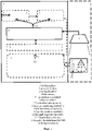
- figure 1 1 shows a schematic functional representation of a dishwasher 1 in which its essential components and also some optional components and their interaction are represented by dashed lines.
- the dishwasher 1 can be designed, for example, as a transport dishwasher, a hood-type dishwasher or as a program machine with a door.
- the dishwasher 1 comprises an optical unit 2 which is designed to record an image of a washing-ware container 3; and a computing unit 6, which is designed to recognize at least one mark 4 applied to the wash-ware container 3 based on the image of the wash-ware container 3 recorded by the optical unit 2 and, based on the recognized at least one marking 4, a status of the loading of the wash-ware container 3 with wash items 14 to be determined, with the computing unit 6 being designed to output the determined state of the loading of the washware container 3 with washware 14 (output 13).
- the dishwasher 1 can also include an optional display device 8 on which the determined state of the loading of the wash-ware container 3 with wash items 14 that is output by the computing unit 6 is displayed graphically.
- the user can make a user input 9 via the display device 8, which causes a corresponding adjustment of one or more operating parameters of the dishwasher 1.
- the display device 8 can prevent incompletely loaded washware containers 3 from being introduced into the dishwasher 1 at all.
- the display device 8 can show sections that are not completely occupied by items to be washed 14 (such as the unoccupied sections 15 in figure 3 ) in the washware container 3 is graphically highlighted for the user, so that the user is able to increase and optimize the loading of the washware container 3 with washware 14 in a targeted manner and thereby contribute to the ecology and economy of the dishwasher 1.
- the operating parameters of the dishwasher 1 can be adjusted by the control unit 7 - either automatically or by triggering the user input 9 - on the basis of the output 13 to the actual state of the loading of the washware container 3 with washware 14, so that the ecology and economy of the dishwasher 1 are also improved .
- the display device 8 can be designed, for example, to graphically display the selected washing program and/or the selected value of the one or more operating parameters.
- the display device 8 can also be designed, for example, to receive an input 9 from a user and the control unit 7 can be designed, based on the input 9 received, to send the selected washing program and/or the selected value of the one or more operating parameters of the dishwasher change.
- an already predefined program could be selected in a first step.
- the user can then based on the output 13 toggle between Washing programs, for example between glasses and plates program, using the user input 9 effect.
- operating parameters in the “sense circle” of the individual washing programs could then also be changed in the background in order to achieve an even better adaptation to the state of the loading of the washware container 3 with washware 14 .
- the Sinner Vietnamese contains the four segments of time, chemistry, temperature and mechanics.
- the dishwasher 1 shown can include one or more treatment zones 11 with dispensing nozzles 12 arranged therein.
- the one or more operating parameters can include the following from the list below, individually or in any combination: a nozzle pressure at the dispensing nozzles 12, a volume flow of the cleaning liquid used by the dishwasher 1 to wash the items to be washed 14, a distribution of sprayed washing liquid within one of the one or more treatment zones 11, a final-rinse quantity of final-rinse liquid sprayed in a final-rinse zone, a temperature of the washing liquid sprayed at the dispensing nozzles 12, a dosage of a washware cleaner within the washing liquid sprayed at the dispensing nozzles 12, a speed of a conveyor belt which washware is conveyed through one of the one or several treatment zones 11 of the dishwasher 1 is transported and/or an exposure time of a washing liquid sprayed through the dispensing nozzles 12 on the washware 14 located in the washware container 3.
- the one or more operating parameters are there i selected in such a way that the program sequence in the dishwasher is improved and in particular that the resources required by the dishwasher (energy, water, chemicals) are used optimally and thus a washing operation that is specially adapted to the load status of the washware container and thus resource-saving can be provided.
- the arithmetic unit 6 described is designed to determine the state of the loading of the washware container 3 with washware 14 without using a comparison of the image of the washware container 3 recorded by the optical unit 2 with a stored reference image. Such a comparison would place a relatively heavy burden on the arithmetic unit 6 with arithmetic operations (for example pixel-by-pixel comparison of recorded image and reference image).
- the arithmetic unit 6 is designed, however, a number of recognized at least one on To determine washware container 3 attached marking 4 within the image of the washware container 3 recorded by the optical unit 2 and to determine the state of the loading of the washware container 3 with washware 14 on the basis of this specific number of markings 4 .
- the number of detected at least one marking 4 applied to the wash-ware container 3 within the image of the wash-ware container 3 recorded by the optical unit 2 can be determined by using common algorithms for pattern recognition.
- the computing unit 6 can run such an algorithm over the recorded image in order to determine the number of markings contained in the image.
- the computing unit 6 can be designed to determine the state of the loading of the washware container 3 with washware 14 by comparing this specific number of markings 4 with a stored reference value.
- the stored reference value can correspond to a washware container 3 that is not loaded with washware 14 .
- the stored reference value can specify a total number of the one or more markings 4 applied to the washware container 3 which are completely visible to the optical unit 2 in the case of a washware container 3 not loaded with washware 14 .
- the computing unit 6 can also be designed to recognize one or more optional type indicators 5 attached to the wash container on the basis of the image recorded by the optical unit 2 of the wash-ware container 3 and based on the recognized one or more type indicators 5 To determine the type of wash tub 3 , the computing unit 6 also being designed to read out the stored reference value from an optional storage medium 10 , which reference value is assigned to the determined type of wash tub 3 .
- the dishwasher 1 can respond optimally to different types of washware containers 3, with the number of possible types of washware containers 3 being small compared to the number of possible types of washware 14 and their options for arrangement in the washware container 3, so that great reliability with high flexibility can be provided for determining a total number of the one or more markings 4 attached to the washware container 3, which would be completely visible to the optical unit 2 in the case of a washware container 3 unloaded with washware 14. Markings 4 that are partially visible indicate occupied sections in the wash-ware container 3.
- the image can be a two-dimensional image.
- the optical unit 2 can include or be a camera.
- the optical unit 2 can be attached above a zone for loading the dishwasher 1 with items to be washed 14 . As indicated by the dashed line in figure 1 shown, the optical unit 2 can be either inside or outside the dishwasher 1 be appropriate.
- the optical unit 2 can be attached outside the dishwasher 1 on a cantilever arm 2a or directly on the housing or a door of the dishwasher 1. In the case of a hood dishwasher, the optical unit 2 can be fastened directly to the hood from the outside. In the case of a transport dishwasher, the optical unit 2 can be fastened above the loading zone. In the case of a programmable machine with a door, the optical unit 2 can be fastened to the dishwasher above the door, with the optical unit 2 then being directed obliquely downwards on the door side.
- the computing unit 6 can be designed to filter or post-process the image of the wash-ware container 3 recorded by the optical unit 2 and to recognize the at least one marking 4 applied to the wash-ware container 3 in the filtered or post-processed image.
- Such filtering or post-processing may include one or more of edge sharpening, contrast alteration, or artifact removal, for example.
- the dishwasher 1 can have a light source (e.g. light source 20 in Figures 4A, 4B , 4C ) that illuminates the washing-ware container and the optical unit 2 thus detects the light of the light source reflected or transmitted by the at least one marking 4 and the type indicator 5 .
- FIGS. 2 and 3 show schematic representations of different possibilities 4a, 4b, 4c, 4d, 4e and 4f of the design of the markings 4 on the wash-ware container 3 and an exemplary representation of the type indicator 5 on the wash-ware container 3, as well as exemplary arrangements of the markings 4 and type indicators 5 the dishwashing container 3.
- the at least one marking 4 attached to the wash-ware container 3 can be attached to the bottom or to a wall of the wash-ware container 3 .
- the one or more type indicators 5 attached to the wash container can be attached to a point (e.g. on the edge) of the wash container 3 where the type indicators 5 are fully visible to the optical unit 2, regardless of the load status of the wash container 3. Both the marking 4 in the case of an unloaded section 15 and the type indicator 5 should be attached so that the optical unit 2 can detect it from above or from below.
- the at least one marking 4 attached to the wash-ware container 3 can differ from the type indicators 5 attached to the wash-ware container 3 in color, shape and/or material.
- the number and design of the markings 4 applied to the washing-ware container 3 are all known to the computing unit 6 . Thus, after any processing, the recorded image is searched for these markings 4 and any type indicators 5 . The respective degree of loading of the washing-ware container 3 can thus be determined on the basis of the counted features 4 .
- a plurality of markings 4 can be applied to the washware container 3, with the washware container 3 comprising a plurality of sections 15 for receiving washware 14, one of the plurality of markings 4 being applied in each of these sections 15, and the plurality of markings 4 on the washware container 3 being those of the Arithmetic unit 6 detected at least one marker 4 include.
- the determined state of the loading of the washware container 3 with washware 14 can include a degree of loading of the washware container 3 with washware 14 .
- the markings 4 applied in the washing items container 3 can no longer be detected by the optics, in particular for the optical unit 2, when items to be washed 14 are occupied. This marking then allows this space or section 15 in the washing-ware container 3 to be recognized as “occupied”.
- one or more markings 4 are attached to the wash-ware container 3, which include the recognized at least one mark 4 attached to the wash-ware container 3, the one or more markings 4 attached to the wash-ware container 3 being laid out when the wash-ware container 3 is occupied by wash items 14 for the optical unit 2 to no longer be fully visible and thereby mark a section 15 of the washing-ware container 3 as being occupied.
- markings 4 can have different shapes, colors and materials, each with different optical properties, and can be permanently attached to the bottom or side wall of the washing-ware container 3 or retrofitted.
- portions 15 in the tub 3 intended for glasses may have circular features 4c, 4f
- portions 15 in the tub 3 intended for plates may have triangular markings 4a, 4d
- portions 15 in the tub 3 designated for Small parts are provided, be equipped with quadrangular features 4b, 4e.
- Markings 4 in different sections 15 can differ in size, colour, shape and orientation.
- the triangle 4a, 4d can be used, for example, for a section 15 of the washing-ware container 3 intended for flat and deep plates.
- the system assumes, for example, that the section 15 of the washing-ware container 3 is loaded with deep plates.
- a large circle 4c could be used for wine glasses.
- the identification of the marking 4 can be such that a noticeable distinction is made for the processing unit 6 even if the glasses are transparent. This can be achieved, for example, by different optical properties, such as refraction, reflection or absorption of light (for example of the light source 20).
- a simple example would be if the marking 4, 4c, 4f were to change solely due to the optical refraction in such a way that it can no longer be recognized completely and precisely by the computing unit 6.
- the at least one marking 4 applied to the washing-ware container 3 recognized by the computing unit 6 can be completely visible to the optical unit 2 .
- the computing unit 6 can be designed to determine a number, an area, a size, a shape or a color of the recognized at least one marking 4, 4a-4f applied to the wash-ware container 3 within the image of the wash-ware container 3 recorded by the optical unit 2 and to determine the state of the loading of the washware container 3 with washware 14 on the basis of a certain number, surface area, size, shape or color.
- the computing unit 6 can be designed to determine the state of the loading of the washware container 3 with washware 14 by means of a comparison of a specific number, surface area, size, shape or color with a stored reference.
- type indicators 5 can also be attached to each wash-ware container 3 in addition to the markings 4 in the wash-ware container 3 in such a way that the computing unit 6 can always recognize them. As a result, the computing unit 6 recognizes what type of wash-ware container 3 it is, even if all sections 15 of the wash-ware container 3 are fully occupied and thus all markings 4 in the wash-ware container 3 are covered.
- a plurality of markings 4 can be attached to the wash-ware container 3, which includes the detected at least one mark 4 attached to the wash-ware container 3, the plurality of markings 4 including one or more markings 4 which are at least partially invisible to the optical unit 2.
- the for the optical unit 2 at least partially invisible one or more markings 4 of the plurality of The arithmetic unit 6 cannot recognize markings 4 .
- the at least one marking 4 recognized by the processing unit 6 can be applied in a section 15 of the plurality of sections 15 of the wash-ware container 3 that is not loaded with washware 14 .
- the processing unit 6 can be designed to determine a number of the recognized at least one marking 4 attached to the washware container 3 within the image of the washware container 3 recorded by the optical unit 2 and, on the basis of this determined number, to determine the state of the loading of the washware container 3 with washware 14 determine, wherein the determined state of the loading of the wash-ware container 3 with wash items includes a degree of loading of the wash-ware container 3 with wash items and the degree of loading of the wash-ware container 3 with wash items 14 by the computing unit 6 by comparing this specific number with the stored number of the plurality Sections 15 of the washware container 3 for receiving washware 14 is determined.
- a marking 4 can also be used which extends over a larger area, for example over a number of sections 15.
- the processing unit 6 can then be designed to determine an area of such a recognized at least one marking 4 applied to the wash-ware container 3 within the image of the wash-ware container 3 recorded by the optical unit 2 and on the basis of a comparison of this determined area with a total area stored in the storage medium 10 the at least one marking 4 applied to the wash-ware container 3 to determine the state of the loading of the wash-ware container 3 with wash items 14 .
- a single, continuous marking area 4 can be attached to the bottom of the washing basket 3 and the load status can be determined on the basis of the area that is still visible to the optical unit 2 .
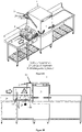
- FIGS. 4A, 4B , 4C show, using a hood type dishwasher 1, where and how the optical unit 2 can be arranged relative to the washing-ware container 3 and the treatment zone 11.
- a zone 30 for loading the dishwasher 1 with items to be washed 14 can be provided on the side of the hood-type dishwasher 1 . From this loading zone 30 , the washware container 3 is introduced into the dishwasher 1 , in particular into the treatment zone 11 . The washware container 3 can be guided into the dishwasher 1 or the treatment zone 11 either manually or by means of an automatic guide device, not shown here.
- the optical unit 2 is attached to the dishwasher 1 from the outside.
- An optional cantilever arm 2a can be attached to the dishwasher 1 from the outside and have the optical unit 2 .
- the optical unit 2 can be a camera.
- the optical unit 2 is arranged outside the dishwasher 1 in such a way that it can receive light reflected or transmitted by the marking 4 and type indicators 5 .
- the optical unit 2 can be arranged outside the dishwasher 1 by means of the cantilever arm 2a in such a way that the optical unit 2 is arranged above the loading zone 30 and thus above the washware container 3 during the loading process. The optical unit 2 then picks up the marking 4 and the optional type indicator 5 from above.
- the dishwasher 1 can include a light source 20 .
- the light source 20 can, for example, below the loading zone 30, as in FIG Figure 4A, 4B shown, and illuminate the marking 4 and the type indicator 5 from below, so that the optical unit 2 receives the light transmitted from the markings 4 and type indicators 5 .
- the light source 20, as in FIG Figures 4A , 4C shown also be arranged on the cantilever arm 2a (above the loading zone 30), so that the optical unit 2 receives, for example, the light from the light source 20 reflected by the markings 4 and type indicators 5.
- Arranging the light source 20 on the cantilever 2a has the advantage that the optical alignment of the optical unit 2 and light source 20 can be better coordinated with one another and also that the cantilever 2a together with the light source 20 and optical unit 2 form an optical system that is portable and can be attached at various points of the dishwasher 1 to determine the state of the loading of the washware container 3 with washware 14.
- the dishwasher 1 can also do without a light source 20, since the light incident from the surroundings is sufficient to use the optical unit 2 to create an image of the marking 4 and the optional type indicator 5 record and using the computing unit 6 of the dishwasher 1 to determine the state of loading of the container 3 with items to be washed 14.
- figure 5 shows a flow chart showing essential and optional (in figure 5 dashed) operations of the method 100 according to the invention for operating a dishwasher 1 indicates.
- the method 100 first begins with the recording of an image of a wash-ware container 3 by means of an optical unit 2.
- a type indicator 5 attached to the wash-ware container 3 is recognized by the computing unit 6 .
- a type of the washing-ware container 3 is then determined by the arithmetic unit 6 on the basis of the recognized type indicator 5 .
- a state of the loading of the washware container 3 with washware 14 is then determined by means of the computing unit 6.
- the determination 105 of a state of loading of the washware container 3 with washware 14 by means of the computing unit 6 can optionally include the following: determining 105a a number of recognized at least one marking applied to the wash-ware container 3 within the image of the wash-ware container recorded by the optical unit 2 .
- the determination 105 of a state of loading of the wash-ware container 3 with wash items 14 by means of the computing unit 6 can optionally also include the following: Queries 105b of the stored reference value, which is assigned to the determined type of wash-ware container 3, by means of the computing unit 6, the reference value being a total number which indicates one or more markings 4 attached to a washing-ware container 3 of the type determined
- the determination 105 of a state of loading of the wash-ware container 3 with wash items 14 by means of the computing unit 6 can optionally also include the following: comparing 105c this specific number of recognized at least one mark 4 applied to the wash-ware container 3 with the queried stored reference value.
- the dishwasher operation can be checked by the control unit 7 in accordance with the determined load status that has been output.
- Operation 107 can include the following: on the basis of the determined state of the loading of the washware container 3 with washware 14 output by the computing unit 6, using the control unit 7 to (automatically) select a wash program and/or a value of an operating parameter of the dishwasher 1 which/r is adapted to the determined state of the load of the washing-ware container 3 .
- the one or more operating parameters can include the following from the list below, either individually or in any combination: a nozzle pressure at the dispensing nozzles 12, a volume flow of the cleaning liquid used by the dishwasher 1 to wash the items to be washed 14, a distribution of sprayed washing liquid within one of the one or more treatment zones 11, a rinsing quantity sprayed in a rinsing zone, a temperature of the rinsing liquid sprayed at the dispensing nozzles 12, a dosage of a dishwashing detergent within the rinsing liquid sprayed at the dispensing nozzles 12, a speed a conveyor belt which transports items to be washed through one of the one or more treatment zones 11 of the dishwasher 1 and/or an exposure time of a washing liquid sprayed through the dispensing nozzles 12 to the items to be washed 14 located in the wash-ware container 3.
- the one or more operating parameters are selected in such a way that the Program flow in the dishwasher is improved and in particular that the resources required by the dishwasher (energy, water, chemicals) are used optimally and thus a specially adapted to the loading status of the washing-ware container and thus resource-saving washing operation can be provided.
- the dishwasher 1 can also include an optional display device 8, on which the determined state of the loading of the washware container 3 with washware 14, which is output by the computing unit 6, is graphically displayed during operation 106.
- the user can make a user input 9 via the display device 8 , which causes one or more of the operating parameters of the dishwasher 1 to be adjusted in operation 107 .
- the display device 8 can graphically highlight to the user sections 15 in the washware container 3 that are not completely occupied by washware, so that the user is able to increase and optimize the loading of the washware container 3 with washware 14 in a targeted manner and thereby to ecology and economy to contribute to the dishwasher.
- operations 106 and/or 107 can be used to adapt the operating parameters of dishwasher 1 to the actual state of loading of washware container 3 with washware 14, so that the ecology and economy of dishwasher 1 are improved.
Landscapes
- Washing And Drying Of Tableware (AREA)
- Table Devices Or Equipment (AREA)
- Enzymes And Modification Thereof (AREA)
- Detergent Compositions (AREA)
Description
- Die vorliegende Erfindung betrifft eine Spülmaschine und ein entsprechendes Verfahren zum Betrieb einer Spülmaschine.
- In Spülmaschinen wird das Spülgut üblicherweise mit Spüllauge gereinigt und anschließend mit klarem Frischwasser nachgespült. Es wird je nach Bauart zwischen Transportgeschirrspülmaschinen (Korb- oder Bandtransportmaschinen), Haubengeschirrspülmaschinen und Programmautomaten unterschieden.
- Geschirrspülmaschinen verfügen typischerweise über eine Behandlungszone, in der das Spülgut mit Wasser und Spülmittel beaufschlagt wird, sowie über eine Zone zum Beladen der Spülmaschine mit Spülgut, wobei diese Zone zum Beladen von Spülgut bei einer Transportgeschirrspülmaschine in der Regel ein Vorhang oder eine Tür umfasst, bei einer Haubengeschirrspülmaschine eine Haube umfasst und bei einem Programmautomaten in der Regel eine Tür umfasst durch die jeweils das Spülgut in die Behandlungszone eingebracht wird.
- Zum Beaufschlagen von zu reinigendem Spülgut mit Spülflüssigkeit verfügt die Geschirrspülmaschine in der Behandlungszone über eine Sprüheinrichtung wie zum Beispiel Sprühdüsen.
- Für eine Beladung der Geschirrspülmaschine mit zu reinigendem Spülgut kommen in der Regel Spülgutbehälter, wie zum Beispiel Spülkörbe, zum Einsatz, die für den Verwender aus der Geschirrspülmaschine bzw. Behandlungszone herausnehmbar ausgebildet sind.
- Insbesondere aus Gründen des Umweltschutzes und des sparsamen Umgangs mit Ressourcen werden immer größere Anforderungen an solche Spülmaschinen gestellt. Das Spülergebnis ist dabei - neben den Betriebsparametern Temperatur der Spülflüssigkeit, Anteil der Lauge, Spülmechanik und Einwirkzeit - stark abhängig von der in dem Spülwasser befindlichen Verschmutzung, die durch das verschmutzte Spülgut in die Spülmaschine eingebracht wird.
- In bestehenden Systemen wird oftmals Energie, sauberes Wasser und Spülmittel verschwendet in dem unvollständig beladene Spülgutbehälter gespült werden, insbesondere genauso gespült werden wie vollständig beladene Spülgutbehälter.
-
US 2012/138092 A1 beschreibt automatischen Geschirrspüler und ein Verfahren zum Steuern des Betriebs des automatischen Geschirrspülers, einschließlich einer Bildgebungsvorrichtung, die wiederholt Bilder eines Unterabschnitts einer Waschkammer aufnimmt, während ein Geschirrkorb von einer Ladeposition in eine Verwendungsposition bewegt wird. Die wiederholte Erfassung von Bildern wird mit der Bewegung des Geschirrkorbs synchronisiert, und Bereiche des Geschirrkorbs, in denen Geschirr vorhanden ist, werden aus den wiederholt aufgenommenen Bildern bestimmt. - Es ist daher eine Aufgabe der vorliegenden Erfindung, eine Spülmaschine zur Verfügung zu stellen, die möglichst ressourcenschonend bei gleichbleibend gutem Spülergebnis spült und gleichzeitig eine hohe Verlässlichkeit und Bedienungsfreundlichkeit bietet.
- Diese Aufgabe wird durch eine Spülmaschine gemäß Anspruch 1 und ein Verfahren zum Betrieb einer solchen Spülmaschine nach Anspruch 11 gelöst. Die Ansprüche 2 bis 10 und 12 bis 14 betreffen besonders vorteilhafte Ausführungsformen.
- Die Erfindung löst diese Aufgabe, weil die erfindungsgemäße Spülmaschine folgendes umfasst: eine optische Einheit, die ausgelegt ist, ein Bild von einem Spülgutbehälter aufzunehmen; und eine Recheneinheit, die ausgelegt ist, auf Basis des von der optischen Einheit aufgenommenen Bildes des Spülgutbehälters mindestens eine am Spülgutbehälter angebrachte Markierung zu erkennen und auf Basis der erkannten mindestens einen Markierung einen Zustand der Beladung des Spülgutbehälters mit Spülgut zu ermitteln, wobei die Recheneinheit ausgelegt ist, den ermittelten Zustand der Beladung des Spülgutbehälters mit Spülgut auszugeben.
- Die Erfindung löst diese Aufgabe, weil das erfindungsgemäße Verfahren zum Betrieb einer Spülmaschine, Folgendes umfassend: Aufnehmen eines Bildes von einem Spülgutbehälter mittels einer optischen Einheit; auf Basis des von der optischen Einheit aufgenommenen Bildes des Spülgutbehälters, Erkennen mindestens einer am Spülgutbehälter angebrachten Markierung mittels einer Recheneinheit; auf Basis der erkannten mindestens einen Markierung, Ermitteln eines Zustands der Beladung des Spülgutbehälters mit Spülgut mittels der Recheneinheit; und Ausgeben des ermittelten Zustands der Beladung des Spülgutbehälters mit Spülgut mittels der Recheneinheit.
- Diese erfindungsgemäßen Spülmaschine und das erfindungsgemäße Verfahren können jeweils den Programmablauf in der Spülmaschine ökologisch und ökonomisch verbessern und die Bedienung für das Spielpersonal vereinfachen. Insbesondere kann verhindert werden, dass unvollständig beladene Spülgutbehälter in die Spülmaschine überhaupt eingebracht werden oder, dass unvollständig beladene Spülgutbehälter so gespült werden wie vollständig beladene Spülgutbehälter. Durch die Ermittlung des Zustands der Beladung des Spülgutbehälters kann auf noch freie Kapazitäten im Spülgutbehälter derart reagiert werden, dass die von der Spülmaschine benötigten Ressourcen optimal verwendet werden und somit ein ressourcenschonender Spülbetrieb bereitgestellt werden kann. Dadurch, dass auf Basis des von der optischen Einheit aufgenommenen Bildes des Spülgutbehälters mindestens eine am Spülgutbehälter angebrachte Markierung erkannt wird und auf Basis der erkannten Markierung der Zustand der Beladung des Spülgutbehälters ermittelt wird, stellt zusätzlich die Vorteile einer einfachen Integrierbarkeit und hohen Wartungsfreiheit des Systems bereit, bei gleichzeitig hohem Nutzen für Ökologie und Ökonomie des Gesamtsystems. Ferner erlaubt die Tatsache, dass der Zustand der Beladung des Spülgutbehälters mittels am Spülgutbehälter angebrachte Markierungen ermittelt wird, dass die Recheneinheit der Spülmaschine kein Spülgut einlernen muss und somit die Ermittlung des Zustands der Beladung des Spülgutbehälters robust gegenüber Veränderungen des Spülguts und dessen Anordnung im Spülgutbehälter ist.
- Diese und weitere Merkmale und Vorteile der Erfindung werden anhand der nachfolgenden detaillierten Beschreibung von weiteren bevorzugten Ausführungsformen besonders deutlich.
-
- Fig. 1
- zeigt eine schematische Funktionsdarstellung einer Geschirrspülmaschine in der ihre wesentlichen Komponenten, und einige optionalen Komponenten, und deren Zusammenwirken dargestellt sind.
- Fig. 2
- zeigt eine schematische Darstellung von Möglichkeiten der Ausgestaltung der Markierungen am Spülgutbehälter sowie des Typ-Indikators am Spülgutbehälter.
- Fig. 3
- zeigt eine beispielhafte Anordnung der Markierungen und Typ-Indikatoren an dem Spülgutbehälter.
- Fig. 4A, 4B, 4C
- zeigen anhand einer Haubengeschirrspülmaschine, wo und wie die optische Einheit relativ zu Spülgutbehälter und Behandlungszone angeordnet sein kann.
- Fig. 5
- zeigt ein Flussdiagramm, welches wesentliche und optionale Operationen des erfindungsgemäßen Verfahrens angibt.
-
Figur 1 zeigt eine schematische Funktionsdarstellung einer Geschirrspülmaschine 1 in der ihre wesentlichen Komponenten, und durch gestrichelte Linien auch einige optionalen Komponenten, und deren Zusammenwirken dargestellt sind. - Die Spülmaschine 1 kann beispielsweise als Transportgeschirrspülmaschine, Haubengeschirrspülmaschine oder als Programmautomat mit Tür ausgebildet sein. Die Spülmaschine 1 umfasst dabei eine optische Einheit 2, die ausgelegt ist, ein Bild von einem Spülgutbehälter 3 aufzunehmen; und eine Recheneinheit 6, die ausgelegt ist, auf Basis des von der optischen Einheit 2 aufgenommenen Bildes des Spülgutbehälters 3 mindestens eine am Spülgutbehälter 3 angebrachte Markierung 4 zu erkennen und auf Basis der erkannten mindestens einen Markierung 4 einen Zustand der Beladung des Spülgutbehälters 3 mit Spülgut 14 zu ermitteln, wobei die Recheneinheit 6 ausgelegt ist, den ermittelten Zustand der Beladung des Spülgutbehälters 3 mit Spülgut 14 auszugeben (Ausgabe 13).
- Diese kann ferner eine optionale Kontrolleinheit 7 umfassen, die ausgelegt ist, auf Basis des von der Recheneinheit 6 ausgegebenen ermittelten Zustands der Beladung des Spülgutbehälters 3 mit Spülgut 14 ein Spülprogramm und/oder einen Wert ein oder mehrerer Betriebsparameter der Spülmaschine 1 auszuwählen, welches/r an den ermittelten Zustand der Beladung des Spülgutbehälters 3 angepasst ist. Alternative oder zusätzlich dazu, kann die Spülmaschine 1 ferner eine optionale Anzeigevorrichtung 8 umfassen, auf der der von der Recheneinheit 6 ausgegebene ermittelte Zustand der Beladung des Spülgutbehälters 3 mit Spülgut 14 grafisch angezeigt wird. Der Benutzer kann in Reaktion über die Anzeigevorrichtung 8 eine Benutzereingabe 9 tätigen, die eine entsprechende Anpassung von ein oder mehreren Betriebsparametern der Spülmaschine 1 bewirkt. Durch diese optionalen Mittel 7 und 8 der Spülmaschine 1 kann somit der Programmablauf in der Spülmaschine ökologisch und ökonomisch verbessert während die Bedienung für das Spülpersonal einfach gehalten wird.
- Insbesondere kann durch die Anzeigevorrichtung 8 verhindert werden, dass unvollständig beladene Spülgutbehälter 3 in die Spülmaschine 1 überhaupt eingebracht werden. Zum Beispiel kann die Anzeigevorrichtung 8 nicht durch Spülgut 14 vollständig belegte Abschnitte (wie die unbelegten Abschnitte 15 in
Figur 3 ) im Spülgutbehälter 3 dem Benutzer grafisch hervorgehoben angezeigt, sodass dieser in die Lage versetzt wird zielgerichtet die Beladung des Spülgutbehälters 3 mit Spülgut 14 zu steigern und zu optimieren und dadurch zu Ökologie und Ökonomie der Spülmaschine 1 beizutragen. - Ferner kann durch Kontrolleinheit 7 - entweder automatisch oder mittels Auslösung durch die Benutzereingabe 9 - auf Basis der Ausgabe 13 Betriebsparameter der Spülmaschine 1 an den tatsächlichen Zustand der Beladung des Spülgutbehälters 3 mit Spülgut 14 angepasst werden, sodass ebenfalls Ökologie und Ökonomie der Spülmaschine 1 verbessert werden.
- Die Anzeigevorrichtung 8 kann beispielsweise ausgelegt sein, das ausgewählte Spülprogramm und/oder den ausgewählten Wert des/r ein oder mehreren Betriebsparameter grafisch anzuzeigen. Die Anzeigevorrichtung 8 kann beispielsweise auch ausgelegt sein, eine Eingabe 9 eines Benutzers zu empfangen und die Kontrolleinheit 7 kann ausgelegt sein, basierend auf der empfangenen Eingabe 9, das ausgewählte Spülprogramm und/oder den ausgewählten Wert des/der ein oder mehrerer Betriebsparameter der Spülmaschine zu verändern.
- Zum Beispiel könnte in einem ersten Schritt ein bereits vordefiniertes Programm ausgewählt werden. Der Benutzer kann dann auf Basis der Ausgabe 13 ein Umschalten zwischen Spülprogrammen, zum Beispiel zwischen Gläser- und Tellerprogramm, mittels der Benutzereingabe 9 bewirken. Zusätzlich könnten dann im Hintergrund noch Betriebsparameter im "Sinnerkreis" der einzelnen Spülprogramme verändert werden, um eine noch bessere Anpassung an den Zustand der Beladung des Spülgutbehälters 3 mit Spülgut 14 zu realisieren. Der Sinnerkreis enthält die vier Segmente Zeit, Chemie, Temperatur und Mechanik.
- Die in
Figur 1 dargestellte Spülmaschine 1 kann eine oder mehrere Behandlungszonen 11 mit darin angeordneten Abgabedüsen 12 umfassen. - Die ein oder mehreren Betriebsparameter (z.B. des Sinnerkreises) können aus der folgenden Auflistung einzeln oder in beliebiger Kombination Folgendes umfassen: einen Düsendruck an den Abgabedüsen 12, einen Volumenstrom der von der Spülmaschine 1 zum Spülen des Spülguts 14 verwendeten Reinigungsflüssigkeit, eine Verteilung von versprühter Spülflüssigkeit innerhalb einer der ein oder mehreren Behandlungszonen 11, eine Nachspülmenge in einer Nachspülzone versprühten Nachspülflüssigkeit, eine Temperatur der an den Abgabedüsen 12 versprühten Spülflüssigkeit, eine Dosierung eines Spülgutreinigers innerhalb der an den Abgabedüsen 12 versprühten Spülflüssigkeit, eine Geschwindigkeit eines Transportbandes welchem Spülgut durch eine der ein oder mehreren Behandlungszonen 11 der Spülmaschine 1 transportiert wird und/oder eine Einwirkzeit einer durch die Abgabedüsen 12 versprühten Spülflüssigkeit auf das im Spülgutbehälter 3 befindliche Spülgut 14. Die ein oder mehreren Betriebsparameter sind dabei derart ausgewählt, dass der Programmablauf in der Spülmaschine verbessert wird und insbesondere, dass die von der Spülmaschine benötigten Ressourcen (Energie, Wasser, Chemikalien) optimal verwendet werden und somit ein speziell an den Beladungszustand des Spülgutbehälters angepasster und damit ressourcenschonender Spülbetrieb bereitgestellt werden kann.
- Neben diesen Vorteilen im Bereich Ökologie und Ökonomie, gibt es jedoch auch noch weitere Vorteile im Bereich der Datenverarbeitung. Die beschriebene Recheneinheit 6 ist ausgelegt, den Zustand der Beladung des Spülgutbehälters 3 mit Spülgut 14 ohne Verwendung eines Vergleichs des von der optischen Einheit 2 aufgenommenen Bildes des Spülgutbehälters 3 mit einem gespeicherten Referenzbildes zu ermitteln. Ein solcher Vergleich würde die Recheneinheit 6 relativ stark mit Rechenoperationen (zum Beispiel pixelweiser Vergleich von aufgenommenen Bild und Referenzbild) belasten. Die Recheneinheit 6 ist hingegen ausgelegt, eine Anzahl der erkannten mindestens einen am Spülgutbehälter 3 angebrachten Markierung 4 innerhalb des von der optischen Einheit 2 aufgenommenen Bildes des Spülgutbehälters 3 zu bestimmen und auf Basis dieser bestimmten Anzahl von Markierungen 4 den Zustand der Beladung des Spülgutbehälters 3 mit Spülgut 14 zu ermitteln. Die Anzahl der erkannten mindestens einen am Spülgutbehälter 3 angebrachten Markierung 4 innerhalb des von der optischen Einheit 2 aufgenommenen Bildes des Spülgutbehälters 3 kann dabei durch Verwendung von gängigen Algorithmen zur Mustererkennung bestimmt werden. Die Recheneinheit 6 kann einen solchen Algorithmus über das aufgenommene Bild laufen lassen um die Anzahl der im Bild enthaltenen Markierungen zu bestimmen. Die Recheneinheit 6 kann ausgelegt sein, den Zustand der Beladung des Spülgutbehälters 3 mit Spülgut 14 mittels eines Vergleichs dieser bestimmten Anzahl von Markierungen 4 mit einem gespeicherten Referenzwert zu ermitteln. Der gespeicherte Referenzwert kann dabei einem mit Spülgut 14 unbeladenen Spülgutbehälter 3 entsprechen. Der gespeicherte Referenzwert kann eine Gesamtanzahl der am Spülgutbehälter 3 angebrachten ein oder mehreren Markierungen 4 angeben, die im Falle eines mit Spülgut 14 unbeladenen Spülgutbehälters 3 für die optische Einheit 2 vollständig sichtbar sind.
- Die Recheneinheit 6 kann dabei ferner ausgelegt sein, auf Basis des von der optischen Einheit 2 aufgenommenen Bildes des Spülgutbehälters 3 ein oder mehrere optionale, am Spülgutbehälter angebrachte, Typ-Indikatoren 5 zu erkennen und auf Basis der erkannten ein oder mehreren Typ-Indikatoren 5 einen Typ des Spülgutbehälters 3 zu ermitteln, wobei die Recheneinheit 6 ferner ausgelegt ist, aus einem optionalen Speichermedium 10 den gespeicherten Referenzwert auszulesen, der zu dem ermittelten Typ des Spülgutbehälters 3 zugeordnet ist. So kann die Spülmaschine 1 jeweils optimal auf unterschiedliche Typen von Spülgutbehälter 3 reagieren, wobei die Anzahl möglicher Typen von Spülgutbehältern 3 gering ist gegenüber der Anzahl möglicher Arten von Spülgut 14 und deren Möglichkeiten der Anordnung im Spülgutbehälter 3, so dass eine große Verlässlichkeit bei hoher Flexibilität bereitgestellt werden kann für die Bestimmung einer Gesamtanzahl der am Spülgutbehälter 3 angebrachten ein oder mehreren Markierungen 4, die im Falle eines mit Spülgut 14 unbeladenen Spülgutbehälters 3 für die optische Einheit 2 vollständig sichtbar wären. Teilweise sichtbare Markierungen 4 markieren dabei belegte Abschnitte im Spülgutbehälter 3.
- Das Bild kann dabei ein zweidimensionales Bild sein. Die optische Einheit 2 kann eine Kamera umfassen oder sein. Die optische Einheit 2 kann über einer Zone zum Beladen der Spülmaschine 1 mit Spülgut 14 angebracht sein. Wie durch die gestrichelte Linie in
Figur 1 dargestellt, kann die optische Einheit 2 entweder innerhalb oder außerhalb der Spülmaschine 1 angebracht sein. Die optische Einheit 2 kann außerhalb der Spülmaschine 1 an einem Kragarm 2a oder unmittelbar an dem Gehäuse oder einer Tür der Spülmaschine 1 angebracht sein. Im Falle einer Haubengeschirrspülmaschine kann die optische Einheit 2 direkt von außen an der Haube befestigt sein. Im Falle einer Transportgeschirrspülmaschine kann eine Befestigungsmöglichkeit für die optische Einheit 2 über der Beladungszone gegeben sein. Im Fall eines Programmautomaten mit einer Tür kann eine Befestigung der optischen Einheit 2 an der Spülmaschine oben über der Tür vorgesehen sein, wobei die optische Einheit 2 dann an der Türseite schräg nach unten gerichtet ist. - Die Recheneinheit 6 kann ausgelegt sein, das von der optischen Einheit 2 aufgenommene Bild des Spülgutbehälters 3 zu filtern oder nachzubearbeiten und die mindestens eine am Spülgutbehälter 3 angebrachte Markierung 4 in dem gefilterten oder nachbearbeiteten Bild zu erkennen. Eine solche Filterung oder Nachbearbeitung kann zum Beispiel ein oder mehrere von Kantenschärfung, Kontrastveränderung oder Entfernung von Artefakten umfassen. Ferner kann die Spülmaschine1 eine Lichtquelle (zum Beispiel Lichtquelle 20 in
Figuren 4A, 4B ,4C ) umfassen, die den Spülgutbehälter ausleuchtet und so die optische Einheit 2 das von der mindestens einen Markierung 4 und des Typ-Indikators 5 reflektierte oder transmittierte Licht der Lichtquelle erfasst. -
Figuren 2 und3 zeigen schematische Darstellungen von verschiedenen Möglichkeiten 4a, 4b, 4c, 4d, 4e und 4f der Ausgestaltung der Markierungen 4 am Spülgutbehälter 3 und eine beispielhafte Darstellung des Typ-Indikators 5 am Spülgutbehälter 3, sowie beispielhafte Anordnungen der Markierungen 4 und Typ-Indikatoren 5 an dem Spülgutbehälter 3. - Die mindestens eine am Spülgutbehälter 3 angebrachte Markierung 4 kann am Boden oder an einer Wand des Spülgutbehälters 3 angebracht sein. Die ein oder mehrere am Spülgutbehälter angebrachten Typ-Indikatoren 5 können an einer Stelle (zum Beispiel am Rand) des Spülgutbehälters 3 angebracht sind, an der die Typ-Indikatoren 5 unabhängig vom Beladungszustand des Spülgutbehälters 3 für die optische Einheit 2 vollständig sichtbar sind. Sowohl die Markierung 4 im Falle der eines unbeladenen Abschnitts 15, als auch der Typ-Indikator 5, sollen von oben oder von unten für die optische Einheit 2 erfassbar angebracht sein.
- Die mindestens eine am Spülgutbehälter 3 angebrachte Markierung 4 kann sich von den am Spülgutbehälter 3 angebrachten Typ-Indikatoren 5 in Farbe, Form und/oder Material unterscheiden.
- Die Anzahl und Ausgestaltung der am Spülgutbehälter 3 angebrachten Markierungen 4 sind der Recheneinheit 6 alle bekannt. Somit wird das aufgenommene Bild nach einer eventuellen Bearbeitung nach diesen Markierungen 4 und eventuellen Typ-Indikatoren 5 durchsucht. So kann anhand der gezählten Merkmale 4 der jeweiligen Beladungsgrad des Spülgutbehälters 3 bestimmt werden.
- Wie in
Figur 3 gezeigt, können mehrere Markierungen 4 am Spülgutbehälter 3 angebracht sein, wobei der Spülgutbehälter 3 mehrere Abschnitte 15 zum Empfangen von Spülgut 14 umfasst, in jeder dieser Abschnitte 15 eine der mehreren Markierungen 4 angebracht ist, und die mehreren Markierungen 4 am Spülgutbehälter 3 die von der Recheneinheit 6 erkannte mindestens eine Markierung 4 umfassen. Der ermittelte Zustand der Beladung des Spülgutbehälters 3 mit Spülgut 14 kann einen Grad der Beladung des Spülgutbehälters 3 mit Spülgut 14 umfassen. - Die im Spülgutbehälter 3 angebrachten Markierungen 4 sind bei Belegung mit Spülgut 14 für die Optik, insbesondere für die optische Einheit 2, nicht mehr zu erfassen. Diese Markierung lassen diesen Platz oder Abschnitt 15 im Spülgutbehälter 3 dann als "belegt" erkennen. Mit anderen Worten sind an dem Spülgutbehälter 3 ein oder mehrere Markierungen 4 angebracht, die die erkannte mindestens eine am Spülgutbehälter 3 angebrachte Markierung 4 umfassen, wobei die ein oder mehreren an dem Spülgutbehälter 3 angebrachten Markierungen 4 ausgelegt sind bei Belegung des Spülgutbehälters 3 mit Spülgut 14 für die optische Einheit 2 nicht mehr vollständig sichtbar zu sein und dadurch einen Abschnitt 15 des Spülgutbehälters 3 als belegt markieren. Diese Markierungen 4 können in verschiedenen Formen, Farben und Materialien mit je verschiedenen optischen Eigenschaften ausgeführt und am Boden oder Seitenwand des Spülgutbehälters 3 fest angebracht oder nachgerüstet sein. So können zum Beispiel Abschnitte 15 im Spülgutbehälter 3, die für Gläser vorgesehen sind, mit runden Merkmalen 4c, 4f, Abschnitte 15 im Spülgutbehälter 3, die für Teller vorgesehen sind, mit dreieckigen Markierungen 4a, 4d und Abschnitte 15 im Spülgutbehälter 3, die für Kleinteile vorgesehen sind, mit viereckigen Merkmalen 4b, 4e ausgestattet sein. Markierungen 4 in verschiedenen Abschnitten 15 können sich durch Größe, Farbe, Form und Ausrichtung unterscheiden. In
Figur 2 sind einige Beispiele für verschiedene Formen und Größen dargestellt. Das Dreieck 4a, 4d kann beispielsweise für einen Abschnitt 15 des Spülgutbehälters 3, der für flache und tiefe Teller vorgesehenes, verwendet werden. Wenn das Dreieck 4d um 90° gedreht erkannt wird, dann nimmt das System zum Beispiel an, dass der Abschnitt 15 des Spülgutbehälters 3 mit tiefen Tellern beladen ist. Ein großer Kreis 4c könnte für Weingläser verwendet werden. Bei Gläsern kann die Erkennung der Markierung 4 so geartet sein, dass auch bei der vorhandenen Transparenz der Gläser eine für die Recheneinheit 6 merkbare Unterscheidung gegeben ist. Dies kann beispielsweise durch unterschiedliche optische Eigenschaften, wie Brechung, Reflexion oder Absorption von Licht (zum Beispiel der Lichtquelle 20), erreicht werden. Ein einfaches Beispiel wäre, wenn sich alleine durch die optische Brechung die Markierung 4, 4c, 4f so verändern würde, dass diese nicht mehr vollständig exakt für die Recheneinheit 6 zu erkennen ist. Die von der Recheneinheit 6 erkannte mindestens eine am Spülgutbehälter 3 angebrachte Markierung 4 kann für die optische Einheit 2 vollständig sichtbar sein. - Die Recheneinheit 6 kann ausgelegt sein, eine Anzahl, einen Flächeninhalt, eine Größe, eine Form oder eine Farbe der erkannten mindestens einen am Spülgutbehälter 3 angebrachten Markierung 4, 4a-4f innerhalb des von der optischen Einheit 2 aufgenommenen Bildes des Spülgutbehälters 3 zu bestimmen und auf Basis von bestimmter/m Anzahl, Flächeninhalt, Größe, Form, oder Farbe den Zustand der Beladung des Spülgutbehälters 3 mit Spülgut 14 zu ermitteln. Die Recheneinheit 6 kann ausgelegt sein, den Zustand der Beladung des Spülgutbehälters 3 mit Spülgut 14 mittels eines Vergleichs von bestimmter/m Anzahl, Flächeninhalt, Größe, Form oder Farbe mit einer gespeicherten Referenz zu ermitteln.
- Wie schon erwähnt, können auf jedem Spülgutbehälter 3 zusätzlich zu den Markierungen 4 im Spülgutbehälter 3 noch Typ-Indikatoren 5 so angebracht sein, dass diese von der Recheneinheit 6 immer zu erkennen sind. Dadurch erkennt die Recheneinheit 6, um welchen Typ des Spülgutbehälters 3 es sich handelt, auch wenn alle Abschnitte 15 des Spülgutbehälters 3 voll belegt und damit alle Markierungen 4 im Spülgutbehälter 3 verdeckt sind.
- Am Spülgutbehälter 3 kann eine Mehrzahl von Markierungen 4 angebracht sein, die die erkannte mindestens eine am Spülgutbehälter 3 angebrachte Markierung 4 umfasst, wobei die Mehrzahl von Markierungen 4 eine oder mehrere Markierungen 4 umfasst, die für die optische Einheit 2 zumindest teilweise nicht sichtbar sind. Die für die optische Einheit 2 zumindest teilweise nicht sichtbaren ein oder mehreren Markierungen 4 der Mehrzahl von Markierungen 4 können von der Recheneinheit 6 nicht erkannt werden. Die von der Recheneinheit 6 erkannte mindestens eine Markierung 4 kann in einem von Spülgut 14 unbeladenen Abschnitts 15 der mehrere Abschnitte 15 des Spülgutbehälters 3 angebracht sein.
- Die Recheneinheit 6 kann ausgelegt sein, eine Anzahl der erkannten mindestens einen am Spülgutbehälter 3 angebrachten Markierung 4 innerhalb des von der optischen Einheit 2 aufgenommenen Bildes des Spülgutbehälters 3 zu bestimmen und auf Basis dieser bestimmten Anzahl den Zustand der Beladung des Spülgutbehälters 3 mit Spülgut 14 zu ermitteln, wobei der ermittelte Zustand der Beladung des Spülgutbehälters 3 mit Spülgut einen Grad der Beladung des Spülgutbehälters 3 mit Spülgut umfasst und der Grad der Beladung des Spülgutbehälters 3 mit Spülgut 14 von der Recheneinheit 6 mittels eines Vergleichs dieser bestimmten Anzahl mit der gespeicherten Anzahl der mehreren Abschnitte 15 des Spülgutbehälters 3 zum Empfangen von Spülgut 14 ermittelt wird.
- Alternativ zu den in
Figuren 2 und dargestellten lokal beschränkten Markierungen 4 kann auch eine Markierung 4 verwendet werden, die sich über einen größeren Bereich, zum Beispiel über mehrerer Abschnitte 15, erstreckt. Die Recheneinheit 6 kann dann ausgelegt sein, einen Flächeninhalt einer solchen erkannten mindestens einen am Spülgutbehälter 3 angebrachten Markierung 4 innerhalb des von der optischen Einheit 2 aufgenommenen Bildes des Spülgutbehälters 3 zu bestimmen und auf Basis eines Vergleichs dieses bestimmten Flächeninhalts mit einer im Speichermedium 10 gespeicherten Gesamtfläche der mindestens einen am Spülgutbehälter 3 angebrachten Markierung 4 den Zustand der Beladung des Spülgutbehälters 3 mit Spülgut 14 zu ermitteln. In anderen Worten, es kann alternativ eine einzige, durchgängige Markierungsfläche 4 am Boden des Spülkorbes 3 angebracht werden und der Beladungszustand kann auf Basis der noch für die optische Einheit 2 sichtbaren Fläche ermittelt werden. - Die hier dargestellten Formen für Markierung 4 und Typ-Indikator 5 sind jedoch nur Beispiele, die die beanspruchten Markierungen und Typ-Indikatoren nicht beschränken, da auch andere Formen für die Markierung 4 und den Typ-Indikator 5 verwendet werden können.
- Die
Figuren 4A, 4B ,4C zeigen anhand einer Haubengeschirrspülmaschine 1, wo und wie die optische Einheit 2 relativ zu Spülgutbehälter 3 und Behandlungszone 11 angeordnet sein kann. - Seitlich der Haubengeschirrspülmaschine 1 kann eine Zone 30 zum Beladen der Spülmaschine 1 mit Spülgut 14 vorgesehen sein. Aus dieser Beladungszone 30 heraus wird der Spülgutbehälter 3 in die Spülmaschine 1, insbesondere in die Behandlungszone 11, eingebracht. Der Spülgutbehälter 3 kann dabei entweder manuell oder mittels einer hier nicht gezeigten automatischen Führungseinrichtung in die Spülmaschine 1 bzw. die Behandlungszone 11 hereingeführt werden.
- Die optische Einheit 2 ist von Außen an der Spülmaschine 1 angebracht. Ein optionaler Kragarm 2a kann von Außen an der Spülmaschine 1 angebracht sein und die optische Einheit 2 aufweisen. Die optische Einheit 2 kann dabei eine Kamera sein. Die optische Einheit 2 ist derart außerhalb der Spülmaschine 1 angeordnet, dass sie von der Markierung 4 und Typ-Indikatoren 5 reflektiertes oder transmittiertes Licht empfangen kann. Wie in
Figuren 4A, 4B ,4C dargestellt, kann die optische Einheit 2 mittels des Kragarms 2a so außerhalb der Spülmaschine 1 angeordnet sein, dass die optische Einheit 2 oberhalb der Beladungszone 30 und damit oberhalb des Spülgutbehälters 3 während des Beladungsvorgangs angeordnet ist. Die optische Einheit 2 nimmt dann die Markierung 4 und den optionalen Typ-Indikator 5 von oben auf. - Ferner kann die Spülmaschine 1 eine Lichtquelle 20 umfassen. Die Lichtquelle 20 kann zum Beispiel unterhalb der Beladungszone 30, wie in der
Figur 4A, 4B dargestellt, angeordnet sein und die Markierung 4 und den Typ-Indikator 5 von unten beleuchten, sodass die optische Einheit 2 das von den Markierungen 4 und Typ-Indikatoren 5 transmittierte Licht empfängt. Alternativ kann die Lichtquelle 20, wie in derFiguren 4A ,4C dargestellt, auch am Kragarm 2a (oberhalb der Beladungszone 30) angeordnet sein, sodass die optische Einheit 2 zum Beispiel das von den Markierungen 4 und Typ-Indikatoren 5 reflektierte Licht der Lichtquelle 20 empfängt. Eine Anordnung der Lichtquelle 20 am Kragarm 2a hat den Vorteil, dass die optische Ausrichtung von optische Einheit 2 und Lichtquelle 20 besser aufeinander abgestimmt werden können und zudem, dass der Kragarm 2a samt Lichtquelle 20 und optischer Einheit 2 ein optisches System bilden, welches portabel ist und an verschiedenen Stellen der Spülmaschine 1 zu Ermittlung des Zustands der Beladung des Spülgutbehälters 3 mit Spülgut 14 angebracht werden kann. Die Spülmaschine 1 kann jedoch auch ohne Lichtquelle 20 auskommen, da das aus der Umgebung einfallende Licht genügt, um mittels der optischen Einheit 2 ein Bild von der Markierung 4 und des optionalen Typ-Indikators 5 aufzunehmen und mittels der Recheneinheit 6 der Spülmaschine 1 den Zustand der Beladung des Gutbehälters 3 mit Spülgut 14 zu ermitteln. - Nach der Behandlung des Spülguts 14 durch die Spülmaschine 1, insbesondere nach dem Spülen des Spülguts 14 in der Behandlungszone 11, kann der Spülgutbehälter 3 samt Spülgut 14 entweder manuell oder mittels eines automatischen Prozesses aus der Spülmaschine 1, insbesondere aus der Behandlungszone 11, wieder entfernt werden. In
Figur 4B ist dazu eine Zone rechts von der Haubengeschirrspülmaschine 1 und gegenüber der Beladungszone 30 vorgesehen um den Spülgutbehälter 3 samt gereinigtem Spülgut 14 zu empfangen -
Figur 5 zeigt ein Flussdiagramm, welches wesentliche und optionale (inFigur 5 gestrichelt) Operationen des erfindungsgemäßen Verfahrens 100 zum Betrieb einer Spülmaschine 1 angibt. - In Operation 101 beginnt das Verfahren 100 zunächst mit dem Aufnehmen eines Bildes von einem Spülgutbehälter 3 mittels einer optischen Einheit 2.
- In der optionalen Operation 102 wird danach auf Basis des von der optischen Einheit 2 aufgenommenen Bildes des Spülgutbehälters 3, ein Erkennen eines am Spülgutbehälter 3 angebrachten Typ-Indikators 5 mittels der Recheneinheit 6 durchgeführt.
- In der optionalen Operation 103 wird danach auf Basis des erkannten Typ-Indikators 5 ein Ermitteln eines Typs des Spülgutbehälters 3 mittels der Recheneinheit 6 durchgeführt.
- In der Operation 104 wird danach auf Basis des von der optischen Einheit 2 aufgenommenen Bildes des Spülgutbehälters 3, ein Erkennen mindestens einer am Spülgutbehälter 3 angebrachten Markierung 4 mittels einer Recheneinheit 6 durchgeführt.
- In der Operation 105 wird danach auf Basis der erkannten mindestens einen Markierung 4, ein Ermitteln eines Zustands der Beladung des Spülgutbehälters 3 mit Spülgut 14 mittels der Recheneinheit 6 durchgeführt.
- Das Ermitteln 105 eines Zustands der Beladung des Spülgutbehälters 3 mit Spülgut 14 mittels der Recheneinheit 6 kann optional Folgendes umfassen: Bestimmen 105a einer Anzahl der erkannten mindestens einen am Spülgutbehälter 3 angebrachten Markierung innerhalb des von der optischen Einheit 2 aufgenommenen Bildes des Spülgutbehälters.
- Das Ermitteln 105 eines Zustands der Beladung des Spülgutbehälters 3 mit Spülgut 14 mittels der Recheneinheit 6 kann optional ferner Folgendes umfassen: Abfragen 105b des gespeicherten Referenzwertes, der zu dem ermittelten Typ des Spülgutbehälters 3 zugeordnet ist, mittels der Recheneinheit 6, wobei der Referenzwert eine Gesamtanzahl der an einem Spülgutbehälter 3 des ermittelten Typs angebrachten ein oder mehreren Markierungen 4 angibt
- Das Ermitteln 105 eines Zustands der Beladung des Spülgutbehälters 3 mit Spülgut 14 mittels der Recheneinheit 6 kann optional ferner Folgendes umfassen: Vergleichen 105c dieser bestimmten Anzahl der erkannten mindestens einer am Spülgutbehälter 3 angebrachten Markierung 4 mit dem abgefragten gespeicherten Referenzwert.
- In der Operation 106 wird nach Operation 105 (zum Beispiel nach der Operation 105c) ein Ausgeben des ermittelten Zustands der Beladung des Spülgutbehälters 3 mit Spülgut 14 mittels der Recheneinheit 6 durchgeführt.
- In der optionalen Operation 107 kann eine Kontrolle des Spülmaschinenbetriebs durch die Kontrolleinheit 7 entsprechend des ausgegebenen ermittelten Beladungszustands durchgeführt werden. Operation 107 kann dabei Folgendes umfassen: auf Basis des von der Recheneinheit 6 ausgegebenen ermittelten Zustands der Beladung des Spülgutbehälters 3 mit Spülgut 14, mittels der Kontrolleinheit 7 ein Spülprogramm und/oder einen Wert eines Betriebsparameters der Spülmaschine 1 (automatisch) auswählen, welches/r an den ermittelten Zustand der Beladung des Spülgutbehälters 3 angepasst ist.
- Die ein oder mehreren Betriebsparameter (z.B. des Sinnerkreises) können aus der folgenden Auflistung einzeln oder in beliebiger Kombination Folgendes umfassen: einen Düsendruck an den Abgabedüsen 12, einen Volumenstrom der von der Spülmaschine 1 zum Spülen des Spülguts 14 verwendeten Reinigungsflüssigkeit, eine Verteilung von versprühter Spülflüssigkeit innerhalb einer der ein oder mehreren Behandlungszonen 11, eine Nachspülmenge in einer Nachspülzone versprühten Nachspülflüssigkeit, eine Temperatur der an den Abgabedüsen 12 versprühten Spülflüssigkeit, eine Dosierung eines Spülgutreinigers innerhalb der an den Abgabedüsen 12 versprühten Spülflüssigkeit, eine Geschwindigkeit eines Transportbandes welchem Spülgut durch eine der ein oder mehreren Behandlungszonen 11 der Spülmaschine 1 transportiert wird und/oder eine Einwirkzeit einer durch die Abgabedüsen 12 versprühten Spülflüssigkeit auf das im Spülgutbehälter 3 befindliche Spülgut 14. Die ein oder mehreren Betriebsparameter sind dabei derart ausgewählt, dass der Programmablauf in der Spülmaschine verbessert wird und insbesondere, dass die von der Spülmaschine benötigten Ressourcen (Energie, Wasser, Chemikalien) optimal verwendet werden und somit ein speziell an den Beladungszustand des Spülgutbehälters angepasster und damit ressourcenschonender Spülbetrieb bereitgestellt werden kann.
- Alternative oder zusätzlich zu der (automatischen) Kontrolle durch die Kontrolleinheit 7, kann die Spülmaschine 1 ferner eine optionale Anzeigevorrichtung 8 umfassen, auf der der von der Recheneinheit 6 ausgegebene ermittelte Zustand der Beladung des Spülgutbehälters 3 mit Spülgut 14 während Operation 106 grafisch angezeigt wird. Der Benutzer kann in Reaktion über die Anzeigevorrichtung 8 eine Benutzereingabe 9 tätigen, die eine Anpassung von ein oder mehreren der Betriebsparameter der Spülmaschine 1 in Operation 107 bewirkt. Ferner kann die Anzeigevorrichtung 8 in Operation 106 nicht durch Spülgut vollständig belegte Abschnitte 15 im Spülgutbehälter 3 dem Benutzer grafisch hervorheben, sodass dieser in die Lage versetzt wird zielgerichtet die Beladung des Spülgutbehälters 3 mit Spülgut 14 zu steigern und zu optimieren und dadurch zu Ökologie und Ökonomie der Spülmaschine beizutragen. Somit kann durch Operationen 106 und/oder 107 die Betriebsparameter der Spülmaschine 1 an den tatsächlichen Zustand der Beladung des Spülgutbehälters 3 mit Spülgut 14 angepasst werden, sodass Ökologie und Ökonomie der Spülmaschine 1 verbessert werden.
Claims (14)
- Eine Spülmaschine (1) umfassend:eine optische Einheit (2), die ausgelegt ist, ein Bild von einem Spülgutbehälter (3) aufzunehmen; undeine Recheneinheit (6), die ausgelegt ist, auf Basis des von der optischen Einheit (2) aufgenommenen Bildes des Spülgutbehälters (3) mindestens eine am Spülgutbehälter (3) angebrachte Markierung (4, 4a-4f) zu erkennen und auf Basis der erkannten mindestens einen Markierung (4, 4a-4f) einen Zustand der Beladung des Spülgutbehälters (3) mit Spülgut (14) zu ermitteln, wobei die Recheneinheit (6) ausgelegt ist, den ermittelten Zustand der Beladung des Spülgutbehälters (3) mit Spülgut (14) auszugeben,wobei an dem Spülgutbehälter (3) ein oder mehrere Markierungen (4, 4a-4f) angebracht sind, die die erkannte mindestens eine am Spülgutbehälter (3) angebrachte Markierung (4, 4a-4f) umfassen;dadurch gekennzeichnet, dassdie ein oder mehreren an dem Spülgutbehälter (3) angebrachten Markierungen (4, 4a-4f) ausgelegt sind bei Belegung des Spülgutbehälters (3) mit Spülgut (14) für die optische Einheit (2) nicht mehr vollständig sichtbar zu sein und dadurch einen Abschnitt (15) des Spülgutbehälters (3) als belegt markieren.
- Spülmaschine (1) nach Anspruch 1, dadurch gekennzeichnet, dass die Spülmaschine (1) ferner eine Kontrolleinheit umfasst, die ausgelegt ist, auf Basis des von der Recheneinheit (6) ausgegebenen ermittelten Zustands der Beladung des Spülgutbehälters (3) mit Spülgut (14) ein Spülprogramm und/oder einen Wert ein oder mehrerer Betriebsparameter der Spülmaschine (1) auszuwählen, welches/r an den ermittelten Zustand der Beladung des Spülgutbehälters (3) angepasst ist.
- Spülmaschine (1) nach einem der Ansprüche 1 bis 2, dadurch gekennzeichnet, dass die Recheneinheit (6) ausgelegt ist, den Zustand der Beladung des Spülgutbehälters (3) mit Spülgut (14) ohne Verwendung eines Vergleichs des von der optischen Einheit (2) aufgenommenen Bildes des Spülgutbehälters (3) mit einem gespeicherten Referenzbildes zu ermitteln.
- Spülmaschine (1) nach einem der vorhergehenden Ansprüche, dadurch gekennzeichnet, dass die Recheneinheit (6) ausgelegt ist, eine Anzahl, einen Flächeninhalt, eine Größe, eine Form oder eine Farbe der erkannten mindestens einen am Spülgutbehälter (3) angebrachten Markierung (4, 4a-4f) innerhalb des von der optischen Einheit (2) aufgenommenen Bildes des Spülgutbehälters (3) zu bestimmen und auf Basis von bestimmter/m Anzahl, Flächeninhalt, Größe, Form, oder Farbe den Zustand der Beladung des Spülgutbehälters (3) mit Spülgut (14) zu ermitteln.
- Spülmaschine (1) nach Anspruch 4, dadurch gekennzeichnet, dass die Recheneinheit (6) ausgelegt ist, den Zustand der Beladung des Spülgutbehälters (3) mit Spülgut (14) mittels eines Vergleichs von bestimmter/m Anzahl, Flächeninhalt, Größe, Form oder Farbe mit einer gespeicherten Referenz zu ermitteln.
- Spülmaschine (1) nach Anspruch 5, dadurch gekennzeichnet, dass die gespeicherte Referenz eine Gesamtanzahl oder eine Gesamtfläche der am Spülgutbehälter (3) angebrachten ein oder mehreren Markierungen (4, 4a-4f) angibt, die im Falle eines mit Spülgut (14) unbeladenen Spülgutbehälters (3) für die optische Einheit (2) vollständig sichtbar sind.
- Spülmaschine (1) nach einem der Ansprüche 5 bis 6, dadurch gekennzeichnet, dass die Recheneinheit (6) ausgelegt ist, auf Basis des von der optischen Einheit (2) aufgenommenen Bildes des Spülgutbehälters (3) ein oder mehrere am Spülgutbehälter (3) angebrachte Typ-Indikatoren (5) zu erkennen und auf Basis der erkannten ein oder mehreren Typ-Indikatoren (5) einen Typ des Spülgutbehälters (3) zu ermitteln, wobei die Recheneinheit (6) ferner ausgelegt ist, aus einem Speichermedium den gespeicherten Referenzwert auszulesen, der zu dem ermittelten Typ des Spülgutbehälters (3) zugeordnet ist.
- Spülmaschine (1) nach Anspruch 7, dadurch gekennzeichnet, dass sich die mindestens eine am Spülgutbehälter (3) angebrachte Markierung (4, 4a-4f) von den am Spülgutbehälter (3) angebrachten Typ-Indikatoren (5) in Farbe, Form und/oder Material unterscheiden.
- Spülmaschine (1) nach einem der Ansprüche 1 bis 8, dadurch gekennzeichnet, dass am Spülgutbehälter (3) eine Mehrzahl von Markierungen (4, 4a-4f) angebracht ist, die die erkannte mindestens eine am Spülgutbehälter (3) angebrachte Markierung (4, 4a-4f) umfasst, und die Recheneinheit (6) ausgelegt ist, eine Anzahl der erkannten mindestens einen am Spülgutbehälter (3) angebrachten Markierung (4, 4a-4f) innerhalb des von der optischen Einheit (2) aufgenommenen Bildes des Spülgutbehälters (3) zu bestimmen und auf Basis dieser bestimmten Anzahl den Zustand der Beladung des Spülgutbehälters (3) mit Spülgut (14) zu ermitteln, wobei der ermittelte Zustand der Beladung des Spülgutbehälters (3) mit Spülgut (14) einen Grad der Beladung des Spülgutbehälters (3) mit Spülgut (14) umfasst und der Grad der Beladung des Spülgutbehälters (3) mit Spülgut (14) von der Recheneinheit (6) mittels eines Vergleichs dieser bestimmten Anzahl mit der gespeicherten Anzahl der mehreren Abschnitte (15) des Spülgutbehälters (3) zum Empfangen von Spülgut (14) ermittelt wird.
- Spülmaschine (1) nach einem der Ansprüche 1 bis 9, dadurch gekennzeichnet, dass die Spülmaschine (1) ferner eine Anzeigevorrichtung (8) umfasst, auf der der von der Recheneinheit (6) ausgegebene ermittelte Zustand der Beladung des Spülgutbehälters (3) mit Spülgut (14) grafisch angezeigt wird.
- Ein Verfahren zum Betrieb einer Spülmaschine (1), das Verfahren umfassend:Aufnehmen eines Bildes von einem Spülgutbehälter (3) mittels einer optischen Einheit (2);auf Basis des von der optischen Einheit (2) aufgenommenen Bildes des Spülgutbehälters (3), Erkennen mindestens einer am Spülgutbehälter (3) angebrachten Markierung (4, 4a-4f) mittels einer Recheneinheit (6), wobei an dem Spülgutbehälter (3) ein oder mehrere Markierungen (4, 4a-4f) angebracht sind, die die erkannte mindestens eine am Spülgutbehälter (3) angebrachte Markierung (4, 4a-4f) umfassen, auf Basis der erkannten mindestens einen Markierung (4, 4a-4f), Ermitteln eines Zustands der Beladung des Spülgutbehälters (3) mit Spülgut (14) mittels der Recheneinheit (6); undAusgeben des ermittelten Zustands der Beladung des Spülgutbehälters (3) mit Spülgut (14) mittels der Recheneinheit (6), dadurch gekennzeichnet, dass die ein oder mehreren an dem Spülgutbehälter (3) angebrachten Markierungen (4, 4a-4f) ausgelegt sind bei Belegung des Spülgutbehälters (3) mit Spülgut (14) für die optische Einheit (2) nicht mehr vollständig sichtbar zu sein und dadurch einen Abschnitt (15) des Spülgutbehälters (3) als belegt markieren.
- Verfahren nach Anspruch 11, wobei das Ermitteln eines Zustands der Beladung des Spülgutbehälters (3) mit Spülgut (14) mittels der Recheneinheit (6) Folgendes umfasst:Bestimmen einer Anzahl der erkannten mindestens einen am Spülgutbehälter (3) angebrachten Markierung (4, 4a-4f) innerhalb des von der optischen Einheit (2) aufgenommenen Bildes des Spülgutbehälters (3); undVergleichen dieser bestimmten Anzahl der erkannten mindestens einer am Spülgutbehälter (3) angebrachten Markierung (4, 4a-4f) mit einem gespeicherten Referenzwert.
- Verfahren nach Anspruch 11 oder 12, ferner umfassend:auf Basis des von der optischen Einheit (2) aufgenommenen Bildes des Spülgutbehälters (3), Erkennen eines am Spülgutbehälter (3) angebrachten Typ-Indikators (5) mittels der Recheneinheit (6);auf Basis des erkannten Typ-Indikators (5), Ermitteln eines Typs des Spülgutbehälters (3) mittels der Recheneinheit (6);Abfragen des gespeicherten Referenzwertes, der zu dem ermittelten Typ des Spülgutbehälters (3) zugeordnet ist, mittels der Recheneinheit (6), wobei der Referenzwert eine Gesamtanzahl der an einem Spülgutbehälter (3) des ermittelten Typs angebrachten ein oder mehreren Markierungen (4, 4a-4f) angibt;
- Verfahren nach einem der Ansprüche 11 bis 13, ferner umfassend:
auf Basis des von der Recheneinheit (6) ausgegebenen ermittelten Zustands der Beladung des Spülgutbehälters (3) mit Spülgut, mittels einer Kontrolleinheit ein Spülprogramm und/oder einen Wert eines Betriebsparameters der Spülmaschine (1) auswählen, welches/r an den ermittelten Zustand der Beladung des Spülgutbehälters (3) angepasst ist.
Applications Claiming Priority (1)
| Application Number | Priority Date | Filing Date | Title |
|---|---|---|---|
| DE102018103888.7A DE102018103888B3 (de) | 2018-02-21 | 2018-02-21 | Spülmaschine mit Beladungserkennung |
Publications (2)
| Publication Number | Publication Date |
|---|---|
| EP3530172A1 EP3530172A1 (de) | 2019-08-28 |
| EP3530172B1 true EP3530172B1 (de) | 2022-06-29 |
Family
ID=65351889
Family Applications (1)
| Application Number | Title | Priority Date | Filing Date |
|---|---|---|---|
| EP19155643.0A Active EP3530172B1 (de) | 2018-02-21 | 2019-02-06 | Spülmaschine mit beladungserkennung |
Country Status (3)
| Country | Link |
|---|---|
| EP (1) | EP3530172B1 (de) |
| DE (1) | DE102018103888B3 (de) |
| ES (1) | ES2924888T3 (de) |
Cited By (1)
| Publication number | Priority date | Publication date | Assignee | Title |
|---|---|---|---|---|
| US12539015B2 (en) | 2023-09-05 | 2026-02-03 | Midea Group Co., Ltd. | Dishwasher with personalized utensil detection and scanning aids therefor |
Families Citing this family (2)
| Publication number | Priority date | Publication date | Assignee | Title |
|---|---|---|---|---|
| IT202000007582A1 (it) * | 2020-04-09 | 2021-10-09 | Candy Spa | Metodo e sistema per determinare informazioni relative al riempimento di una lavastoviglie e per preparare un ciclo di lavaggio della lavastoviglie |
| DE102024106909A1 (de) * | 2024-03-11 | 2025-09-11 | Winterhalter Product & Technology GmbH | System zur optischen Spülguterkennung bei einer Spülmaschine |
Family Cites Families (6)
| Publication number | Priority date | Publication date | Assignee | Title |
|---|---|---|---|---|
| DE10048081A1 (de) * | 2000-09-28 | 2002-04-18 | Miele & Cie | Verfahren zur Erkennung der Spülgutbeladung und/oder des Verschmutzungsgrades von Spülgut in einer programmgesteuerten Geschirrspülmaschine und Geschirrspülmaschine dafür |
| EP1925250A1 (de) * | 2006-11-23 | 2008-05-28 | Electrolux Home Products N.V. | Geschirrspülmaschine mit einer Alarmvorrichtung |
| US7935194B2 (en) * | 2007-08-27 | 2011-05-03 | Whirlpool Corporation | Dishwasher with targeted sensing |
| DE102010003687A1 (de) * | 2010-04-07 | 2011-10-13 | BSH Bosch und Siemens Hausgeräte GmbH | Geschirrspülmaschine mit einer optischen Anzeigeeinrichtung |
| US8696827B2 (en) | 2010-12-01 | 2014-04-15 | Whirlpool Corporation | Dishwasher with imaging device for measuring load characteristics and a method for controlling same |
| DE102015215984A1 (de) * | 2015-08-21 | 2017-03-09 | BSH Hausgeräte GmbH | Wasserführendes Haushaltsgerät und Verfahren zum Betreiben eines wasserführenden Haushaltsgeräts |
-
2018
- 2018-02-21 DE DE102018103888.7A patent/DE102018103888B3/de active Active
-
2019
- 2019-02-06 EP EP19155643.0A patent/EP3530172B1/de active Active
- 2019-02-06 ES ES19155643T patent/ES2924888T3/es active Active
Cited By (1)
| Publication number | Priority date | Publication date | Assignee | Title |
|---|---|---|---|---|
| US12539015B2 (en) | 2023-09-05 | 2026-02-03 | Midea Group Co., Ltd. | Dishwasher with personalized utensil detection and scanning aids therefor |
Also Published As
| Publication number | Publication date |
|---|---|
| EP3530172A1 (de) | 2019-08-28 |
| DE102018103888B3 (de) | 2019-06-13 |
| ES2924888T3 (es) | 2022-10-11 |
Similar Documents
| Publication | Publication Date | Title |
|---|---|---|
| EP2434936B1 (de) | Geschirrspülmaschine | |
| DE102020112205B4 (de) | Geschirrspülmaschine mit einer Bilderfassungseinrichtung und Verfahren zum Betreiben einer derartigen Geschirrspülmaschine | |
| EP3654815B1 (de) | Haushaltsgeschirrspülmaschine und verfahren zum betreiben einer haushaltsgeschirrspülmaschine | |
| DE10039408B4 (de) | Haushaltsmaschine | |
| DE10048081A1 (de) | Verfahren zur Erkennung der Spülgutbeladung und/oder des Verschmutzungsgrades von Spülgut in einer programmgesteuerten Geschirrspülmaschine und Geschirrspülmaschine dafür | |
| DE102017126856A1 (de) | Spülmaschine sowie Verfahren zum Reinigen von Spülgut in einer Spülmaschine | |
| EP2510863B1 (de) | Geschirrspülmaschine mit variabler Direktbesprühung | |
| DE102018009311A1 (de) | Spülmaschine und Verfahren zum Ermitteln von Spülgutinformationen einer Spülmaschine | |
| DE102011054150A1 (de) | Geschirrspüler mit mehreren Behandlungskammern | |
| DE102020128333A1 (de) | Transportspülmaschine sowie verfahren zum betreiben einer transportspülmaschine | |
| DE102005014353A1 (de) | Transportspülmaschine und Verfahren hierfür | |
| DE102018202092A1 (de) | Verfahren zum Betreiben einer Haushaltsgeschirrspülmaschine, Haushaltsgeschirrspülmaschine und System | |
| DE102017219806A1 (de) | Handscanner zur verbesserten Fleckenerkennung, System mit einem solchen Handscanner und Verfahren zu seinem Betrieb | |
| DE102018103888B3 (de) | Spülmaschine mit Beladungserkennung | |
| DE102019111848B4 (de) | System zur optischen Spülguterkennung bei Spülmaschinen, Verfahren zur optischen Spülguterkennung, Spülmaschine mit einem optischen Spülguterkennungssystem sowie Verfahren zum Betreiben einer solchen Spülmaschine | |
| DE102019102800A1 (de) | System zum Beladen einer Spülmaschine und Spülmaschine mit einem derartigen System | |
| DE102020123416A1 (de) | Verfahren zum Reinigen von Spülgut in einer Geschirrspülmaschine und Geschirrspülmaschine | |
| DE102020208346A1 (de) | System mit einer Geschirrspülmaschine und Verfahren zum Betreiben einer Geschirrspülmaschine | |
| DE10048086A1 (de) | Verfahren zur Beladungserkennung einer programmgesteuerten Geschirrspülmaschine und Geschirrspülmaschine zur Durchführung des Verfahrens | |
| EP4106596B1 (de) | System mit einer geschirrspülmaschine und verfahren zum betreiben einer geschirrspülmaschine | |
| DE3908438A1 (de) | Programmgesteuerte waschmaschine | |
| DE102011053548A1 (de) | Verfahren zur Reinigung eines Spülflotten-Speicherbehälters | |
| WO2025190614A1 (de) | System zur optischen spülguterkennung bei einer spülmaschine | |
| BE1031766B1 (de) | Verfahren und Steuervorrichtung zum Anpassen eines Reinigungsvorgangs in einem Reinigungsgerät, Reinigungsgerät | |
| EP4213695A1 (de) | System mit einer geschirrspülmaschine, verfahren zum betreiben einer geschirrspülmaschine und computerprogrammprodukt |
Legal Events
| Date | Code | Title | Description |
|---|---|---|---|
| PUAI | Public reference made under article 153(3) epc to a published international application that has entered the european phase |
Free format text: ORIGINAL CODE: 0009012 |
|
| STAA | Information on the status of an ep patent application or granted ep patent |
Free format text: STATUS: THE APPLICATION HAS BEEN PUBLISHED |
|
| AK | Designated contracting states |
Kind code of ref document: A1 Designated state(s): AL AT BE BG CH CY CZ DE DK EE ES FI FR GB GR HR HU IE IS IT LI LT LU LV MC MK MT NL NO PL PT RO RS SE SI SK SM TR |
|
| AX | Request for extension of the european patent |
Extension state: BA ME |
|
| STAA | Information on the status of an ep patent application or granted ep patent |
Free format text: STATUS: REQUEST FOR EXAMINATION WAS MADE |
|
| 17P | Request for examination filed |
Effective date: 20200220 |
|
| RBV | Designated contracting states (corrected) |
Designated state(s): AL AT BE BG CH CY CZ DE DK EE ES FI FR GB GR HR HU IE IS IT LI LT LU LV MC MK MT NL NO PL PT RO RS SE SI SK SM TR |
|
| GRAP | Despatch of communication of intention to grant a patent |
Free format text: ORIGINAL CODE: EPIDOSNIGR1 |
|
| STAA | Information on the status of an ep patent application or granted ep patent |
Free format text: STATUS: GRANT OF PATENT IS INTENDED |
|
| RIC1 | Information provided on ipc code assigned before grant |
Ipc: A47L 15/50 20060101ALN20220317BHEP Ipc: A47L 15/42 20060101AFI20220317BHEP |
|
| INTG | Intention to grant announced |
Effective date: 20220330 |
|
| GRAS | Grant fee paid |
Free format text: ORIGINAL CODE: EPIDOSNIGR3 |
|
| GRAA | (expected) grant |
Free format text: ORIGINAL CODE: 0009210 |
|
| STAA | Information on the status of an ep patent application or granted ep patent |
Free format text: STATUS: THE PATENT HAS BEEN GRANTED |
|
| AK | Designated contracting states |
Kind code of ref document: B1 Designated state(s): AL AT BE BG CH CY CZ DE DK EE ES FI FR GB GR HR HU IE IS IT LI LT LU LV MC MK MT NL NO PL PT RO RS SE SI SK SM TR |
|
| REG | Reference to a national code |
Ref country code: CH Ref legal event code: EP |
|
| REG | Reference to a national code |
Ref country code: DE Ref legal event code: R096 Ref document number: 502019004762 Country of ref document: DE |
|
| REG | Reference to a national code |
Ref country code: AT Ref legal event code: REF Ref document number: 1500736 Country of ref document: AT Kind code of ref document: T Effective date: 20220715 |
|
| REG | Reference to a national code |
Ref country code: IE Ref legal event code: FG4D Free format text: LANGUAGE OF EP DOCUMENT: GERMAN |
|
| REG | Reference to a national code |
Ref country code: SE Ref legal event code: TRGR |
|
| REG | Reference to a national code |
Ref country code: LT Ref legal event code: MG9D |
|
| REG | Reference to a national code |
Ref country code: ES Ref legal event code: FG2A Ref document number: 2924888 Country of ref document: ES Kind code of ref document: T3 Effective date: 20221011 |
|
| PG25 | Lapsed in a contracting state [announced via postgrant information from national office to epo] |
Ref country code: NO Free format text: LAPSE BECAUSE OF FAILURE TO SUBMIT A TRANSLATION OF THE DESCRIPTION OR TO PAY THE FEE WITHIN THE PRESCRIBED TIME-LIMIT Effective date: 20220929 Ref country code: LT Free format text: LAPSE BECAUSE OF FAILURE TO SUBMIT A TRANSLATION OF THE DESCRIPTION OR TO PAY THE FEE WITHIN THE PRESCRIBED TIME-LIMIT Effective date: 20220629 Ref country code: HR Free format text: LAPSE BECAUSE OF FAILURE TO SUBMIT A TRANSLATION OF THE DESCRIPTION OR TO PAY THE FEE WITHIN THE PRESCRIBED TIME-LIMIT Effective date: 20220629 Ref country code: GR Free format text: LAPSE BECAUSE OF FAILURE TO SUBMIT A TRANSLATION OF THE DESCRIPTION OR TO PAY THE FEE WITHIN THE PRESCRIBED TIME-LIMIT Effective date: 20220930 Ref country code: FI Free format text: LAPSE BECAUSE OF FAILURE TO SUBMIT A TRANSLATION OF THE DESCRIPTION OR TO PAY THE FEE WITHIN THE PRESCRIBED TIME-LIMIT Effective date: 20220629 Ref country code: BG Free format text: LAPSE BECAUSE OF FAILURE TO SUBMIT A TRANSLATION OF THE DESCRIPTION OR TO PAY THE FEE WITHIN THE PRESCRIBED TIME-LIMIT Effective date: 20220929 |
|
| REG | Reference to a national code |
Ref country code: NL Ref legal event code: MP Effective date: 20220629 |
|
| PG25 | Lapsed in a contracting state [announced via postgrant information from national office to epo] |
Ref country code: RS Free format text: LAPSE BECAUSE OF FAILURE TO SUBMIT A TRANSLATION OF THE DESCRIPTION OR TO PAY THE FEE WITHIN THE PRESCRIBED TIME-LIMIT Effective date: 20220629 Ref country code: LV Free format text: LAPSE BECAUSE OF FAILURE TO SUBMIT A TRANSLATION OF THE DESCRIPTION OR TO PAY THE FEE WITHIN THE PRESCRIBED TIME-LIMIT Effective date: 20220629 |
|
| PG25 | Lapsed in a contracting state [announced via postgrant information from national office to epo] |
Ref country code: NL Free format text: LAPSE BECAUSE OF FAILURE TO SUBMIT A TRANSLATION OF THE DESCRIPTION OR TO PAY THE FEE WITHIN THE PRESCRIBED TIME-LIMIT Effective date: 20220629 |
|
| PG25 | Lapsed in a contracting state [announced via postgrant information from national office to epo] |
Ref country code: SM Free format text: LAPSE BECAUSE OF FAILURE TO SUBMIT A TRANSLATION OF THE DESCRIPTION OR TO PAY THE FEE WITHIN THE PRESCRIBED TIME-LIMIT Effective date: 20220629 Ref country code: SK Free format text: LAPSE BECAUSE OF FAILURE TO SUBMIT A TRANSLATION OF THE DESCRIPTION OR TO PAY THE FEE WITHIN THE PRESCRIBED TIME-LIMIT Effective date: 20220629 Ref country code: RO Free format text: LAPSE BECAUSE OF FAILURE TO SUBMIT A TRANSLATION OF THE DESCRIPTION OR TO PAY THE FEE WITHIN THE PRESCRIBED TIME-LIMIT Effective date: 20220629 Ref country code: PT Free format text: LAPSE BECAUSE OF FAILURE TO SUBMIT A TRANSLATION OF THE DESCRIPTION OR TO PAY THE FEE WITHIN THE PRESCRIBED TIME-LIMIT Effective date: 20221031 Ref country code: EE Free format text: LAPSE BECAUSE OF FAILURE TO SUBMIT A TRANSLATION OF THE DESCRIPTION OR TO PAY THE FEE WITHIN THE PRESCRIBED TIME-LIMIT Effective date: 20220629 |
|
| PG25 | Lapsed in a contracting state [announced via postgrant information from national office to epo] |
Ref country code: PL Free format text: LAPSE BECAUSE OF FAILURE TO SUBMIT A TRANSLATION OF THE DESCRIPTION OR TO PAY THE FEE WITHIN THE PRESCRIBED TIME-LIMIT Effective date: 20220629 Ref country code: IS Free format text: LAPSE BECAUSE OF FAILURE TO SUBMIT A TRANSLATION OF THE DESCRIPTION OR TO PAY THE FEE WITHIN THE PRESCRIBED TIME-LIMIT Effective date: 20221029 |
|
| REG | Reference to a national code |
Ref country code: DE Ref legal event code: R097 Ref document number: 502019004762 Country of ref document: DE |
|
| PG25 | Lapsed in a contracting state [announced via postgrant information from national office to epo] |
Ref country code: AL Free format text: LAPSE BECAUSE OF FAILURE TO SUBMIT A TRANSLATION OF THE DESCRIPTION OR TO PAY THE FEE WITHIN THE PRESCRIBED TIME-LIMIT Effective date: 20220629 |
|
| PG25 | Lapsed in a contracting state [announced via postgrant information from national office to epo] |
Ref country code: DK Free format text: LAPSE BECAUSE OF FAILURE TO SUBMIT A TRANSLATION OF THE DESCRIPTION OR TO PAY THE FEE WITHIN THE PRESCRIBED TIME-LIMIT Effective date: 20220629 Ref country code: CZ Free format text: LAPSE BECAUSE OF FAILURE TO SUBMIT A TRANSLATION OF THE DESCRIPTION OR TO PAY THE FEE WITHIN THE PRESCRIBED TIME-LIMIT Effective date: 20220629 |
|
| PLBE | No opposition filed within time limit |
Free format text: ORIGINAL CODE: 0009261 |
|
| STAA | Information on the status of an ep patent application or granted ep patent |
Free format text: STATUS: NO OPPOSITION FILED WITHIN TIME LIMIT |
|
| 26N | No opposition filed |
Effective date: 20230330 |
|
| P01 | Opt-out of the competence of the unified patent court (upc) registered |
Effective date: 20230421 |
|
| PG25 | Lapsed in a contracting state [announced via postgrant information from national office to epo] |
Ref country code: SI Free format text: LAPSE BECAUSE OF FAILURE TO SUBMIT A TRANSLATION OF THE DESCRIPTION OR TO PAY THE FEE WITHIN THE PRESCRIBED TIME-LIMIT Effective date: 20220629 |
|
| PG25 | Lapsed in a contracting state [announced via postgrant information from national office to epo] |
Ref country code: MC Free format text: LAPSE BECAUSE OF FAILURE TO SUBMIT A TRANSLATION OF THE DESCRIPTION OR TO PAY THE FEE WITHIN THE PRESCRIBED TIME-LIMIT Effective date: 20220629 |
|
| REG | Reference to a national code |
Ref country code: BE Ref legal event code: MM Effective date: 20230228 |
|
| PG25 | Lapsed in a contracting state [announced via postgrant information from national office to epo] |
Ref country code: LU Free format text: LAPSE BECAUSE OF NON-PAYMENT OF DUE FEES Effective date: 20230206 |
|
| REG | Reference to a national code |
Ref country code: IE Ref legal event code: MM4A |
|
| PG25 | Lapsed in a contracting state [announced via postgrant information from national office to epo] |
Ref country code: IE Free format text: LAPSE BECAUSE OF NON-PAYMENT OF DUE FEES Effective date: 20230206 |
|
| PG25 | Lapsed in a contracting state [announced via postgrant information from national office to epo] |
Ref country code: BE Free format text: LAPSE BECAUSE OF NON-PAYMENT OF DUE FEES Effective date: 20230228 |
|
| PG25 | Lapsed in a contracting state [announced via postgrant information from national office to epo] |
Ref country code: BG Free format text: LAPSE BECAUSE OF FAILURE TO SUBMIT A TRANSLATION OF THE DESCRIPTION OR TO PAY THE FEE WITHIN THE PRESCRIBED TIME-LIMIT Effective date: 20220629 |
|
| PG25 | Lapsed in a contracting state [announced via postgrant information from national office to epo] |
Ref country code: BG Free format text: LAPSE BECAUSE OF FAILURE TO SUBMIT A TRANSLATION OF THE DESCRIPTION OR TO PAY THE FEE WITHIN THE PRESCRIBED TIME-LIMIT Effective date: 20220629 |
|
| REG | Reference to a national code |
Ref country code: AT Ref legal event code: MM01 Ref document number: 1500736 Country of ref document: AT Kind code of ref document: T Effective date: 20240206 |
|
| PG25 | Lapsed in a contracting state [announced via postgrant information from national office to epo] |
Ref country code: AT Free format text: LAPSE BECAUSE OF NON-PAYMENT OF DUE FEES Effective date: 20240206 |
|
| PG25 | Lapsed in a contracting state [announced via postgrant information from national office to epo] |
Ref country code: CY Free format text: LAPSE BECAUSE OF FAILURE TO SUBMIT A TRANSLATION OF THE DESCRIPTION OR TO PAY THE FEE WITHIN THE PRESCRIBED TIME-LIMIT; INVALID AB INITIO Effective date: 20190206 |
|
| PG25 | Lapsed in a contracting state [announced via postgrant information from national office to epo] |
Ref country code: HU Free format text: LAPSE BECAUSE OF FAILURE TO SUBMIT A TRANSLATION OF THE DESCRIPTION OR TO PAY THE FEE WITHIN THE PRESCRIBED TIME-LIMIT; INVALID AB INITIO Effective date: 20190206 |
|
| PG25 | Lapsed in a contracting state [announced via postgrant information from national office to epo] |
Ref country code: TR Free format text: LAPSE BECAUSE OF FAILURE TO SUBMIT A TRANSLATION OF THE DESCRIPTION OR TO PAY THE FEE WITHIN THE PRESCRIBED TIME-LIMIT Effective date: 20220629 |
|
| REG | Reference to a national code |
Ref country code: CH Ref legal event code: U11 Free format text: ST27 STATUS EVENT CODE: U-0-0-U10-U11 (AS PROVIDED BY THE NATIONAL OFFICE) Effective date: 20260301 |
|
| PGFP | Annual fee paid to national office [announced via postgrant information from national office to epo] |
Ref country code: SE Payment date: 20260223 Year of fee payment: 8 |
|
| PGFP | Annual fee paid to national office [announced via postgrant information from national office to epo] |
Ref country code: GB Payment date: 20260223 Year of fee payment: 8 |
|
| PGFP | Annual fee paid to national office [announced via postgrant information from national office to epo] |
Ref country code: ES Payment date: 20260317 Year of fee payment: 8 |
|
| PGFP | Annual fee paid to national office [announced via postgrant information from national office to epo] |
Ref country code: DE Payment date: 20260220 Year of fee payment: 8 |
|
| PGFP | Annual fee paid to national office [announced via postgrant information from national office to epo] |
Ref country code: AT Payment date: 20260410 Year of fee payment: 5 |
|
| PGFP | Annual fee paid to national office [announced via postgrant information from national office to epo] |
Ref country code: IT Payment date: 20260220 Year of fee payment: 8 |
|
| PGFP | Annual fee paid to national office [announced via postgrant information from national office to epo] |
Ref country code: FR Payment date: 20260227 Year of fee payment: 8 |
|
| PGFP | Annual fee paid to national office [announced via postgrant information from national office to epo] |
Ref country code: CH Payment date: 20260301 Year of fee payment: 8 |