EP3529879B1 - Kraftstoffpumpe - Google Patents
Kraftstoffpumpe Download PDFInfo
- Publication number
- EP3529879B1 EP3529879B1 EP17781080.1A EP17781080A EP3529879B1 EP 3529879 B1 EP3529879 B1 EP 3529879B1 EP 17781080 A EP17781080 A EP 17781080A EP 3529879 B1 EP3529879 B1 EP 3529879B1
- Authority
- EP
- European Patent Office
- Prior art keywords
- housing
- motor housing
- pump
- fuel
- fuel pump
- Prior art date
- Legal status (The legal status is an assumption and is not a legal conclusion. Google has not performed a legal analysis and makes no representation as to the accuracy of the status listed.)
- Active
Links
Images



Classifications
-
- F—MECHANICAL ENGINEERING; LIGHTING; HEATING; WEAPONS; BLASTING
- F02—COMBUSTION ENGINES; HOT-GAS OR COMBUSTION-PRODUCT ENGINE PLANTS
- F02M—SUPPLYING COMBUSTION ENGINES IN GENERAL WITH COMBUSTIBLE MIXTURES OR CONSTITUENTS THEREOF
- F02M37/00—Apparatus or systems for feeding liquid fuel from storage containers to carburettors or fuel-injection apparatus; Arrangements for purifying liquid fuel specially adapted for, or arranged on, internal-combustion engines
- F02M37/04—Feeding by means of driven pumps
- F02M37/08—Feeding by means of driven pumps electrically driven
- F02M37/10—Feeding by means of driven pumps electrically driven submerged in fuel, e.g. in reservoir
-
- H—ELECTRICITY
- H02—GENERATION; CONVERSION OR DISTRIBUTION OF ELECTRIC POWER
- H02K—DYNAMO-ELECTRIC MACHINES
- H02K5/00—Casings; Enclosures; Supports
- H02K5/04—Casings or enclosures characterised by the shape, form or construction thereof
- H02K5/12—Casings or enclosures characterised by the shape, form or construction thereof specially adapted for operating in liquid or gas
- H02K5/132—Submersible electric motors
-
- F—MECHANICAL ENGINEERING; LIGHTING; HEATING; WEAPONS; BLASTING
- F02—COMBUSTION ENGINES; HOT-GAS OR COMBUSTION-PRODUCT ENGINE PLANTS
- F02M—SUPPLYING COMBUSTION ENGINES IN GENERAL WITH COMBUSTIBLE MIXTURES OR CONSTITUENTS THEREOF
- F02M37/00—Apparatus or systems for feeding liquid fuel from storage containers to carburettors or fuel-injection apparatus; Arrangements for purifying liquid fuel specially adapted for, or arranged on, internal-combustion engines
- F02M37/0011—Constructional details; Manufacturing or assembly of elements of fuel systems; Materials therefor
-
- H—ELECTRICITY
- H02—GENERATION; CONVERSION OR DISTRIBUTION OF ELECTRIC POWER
- H02K—DYNAMO-ELECTRIC MACHINES
- H02K5/00—Casings; Enclosures; Supports
- H02K5/04—Casings or enclosures characterised by the shape, form or construction thereof
- H02K5/22—Auxiliary parts of casings not covered by groups H02K5/06-H02K5/20, e.g. shaped to form connection boxes or terminal boxes
- H02K5/225—Terminal boxes or connection arrangements
Definitions
- the invention relates to a fuel pump with an electric motor and with a pump stage, with a motor housing of the electric motor, with a pump housing of the pump stage and with a sheet metal jacket that engages behind the edges of the motor housing and the pump housing, the motor housing being designed to hold a stator of the electric motor that encloses a rotor wherein the motor housing has a stator-retaining portion made of plastic and wherein, seen from the stator, the edge of the motor housing for the metal jacket is arranged on the side facing the pump housing.
- Such fuel pumps are frequently used in today's motor vehicles and are known from practice.
- the electric motor and the pump stage are rolled with the metal jacket in such a way that both the electric motor and the pump stage are encapsulated and enclosed in a sealed manner.
- An interface designed on the pressure side to the electric motor on the one hand and an arrangement of an axially acting seal or axial seal on the suction side on the other hand influence a straining of the pump stage that occurs when the metal jacket rolls. This tension extends over the entire pump stage and leads to a statically excessive or indeterminate installation situation of the pump stage.
- the pump stage of the fuel pump can be designed as a peripheral pump, as a side channel pump or as a screw pump.
- the disadvantage of the known fuel pump is that the metal jacket is a very expensive component.
- the metal jacket closes the radial circumference of the Electric motor and the pump stage, so that all connections of the fuel pump are led away axially.
- the known fuel pump therefore has particularly large axial dimensions.
- large axial dimensions are very disruptive when the fuel pump is to be placed inside a fuel tank.
- the pamphlet DE 10 2005 015 014 A1 discloses a fuel pump with an electric motor that drives a pump stage through which fuel can be pumped.
- the electric motor has a stator and a rotor.
- the motor housing of the electric motor is connected to a pump stage housing of the pump stage via a metal jacket, in that the metal jacket is cast with the motor housing.
- the pamphlet JP 5338733 B2 discloses a fuel pump having an electric motor, a motor housing accommodating the electric motor, a pump stage, and a pump stage housing accommodating the pump stage.
- the pump stage housing is fixed to the motor housing via a snap-in connection.
- the invention is based on the problem of developing a fuel pump of the type mentioned at the outset in such a way that it can be manufactured particularly inexpensively and has particularly small dimensions.
- this problem is solved in that the metal casing engages behind the edges with a curl in each case, such that the pump housing is prestressed against the motor housing.
- the sheet-metal jacket extends exclusively from the edge of the motor housing facing the pump housing to over the pump housing. Thanks to the invention, the majority of the area of the electric motor is not covered by the sheet metal jacket. This allows the sheet metal jacket particularly make it short.
- the fuel pump according to the invention can therefore be manufactured particularly inexpensively. Furthermore, connections can be discharged radially from the section of the electric motor made of plastic. This contributes to the particularly small dimensions of the fuel pump.
- the fuel pump can be manufactured particularly cost-effectively if the height of the metal casing is at most 50% of the sum of the heights of the pump housing and the motor housing.
- connection contacts of the stator In the case of known fuel pumps, fuel generally flows around connection contacts of the stator. To avoid corrosion, very expensive seals and coatings of the connection contacts are known. According to another advantageous development of the invention, expensive sealing of connection contacts of the electric motor can be easily avoided if connection contacts of the stator are enclosed in a sealed manner by the plastic of the motor housing.
- the section of the motor housing made of plastic is preferably manufactured particularly cost-effectively using the injection molding process.
- the number of components of the fuel pump can be kept particularly low if the section of the motor housing made of plastic has a connecting piece for a fuel line.
- This design avoids a cover for the connecting piece that has to be mounted separately.
- the fuel pump has a particularly low overall height when the connecting piece is guided radially away from the motor housing.
- the fuel pump can also be arranged in low fuel tanks.
- the connecting piece helps to further reduce the axial dimensions of the fuel pump if the connecting piece is arranged at the axial height of the stator.
- ducts for guiding fuel through the fuel pump can be manufactured particularly easily if a cover of a duct leading to a connecting piece is sealed on the section of the motor housing made of plastic.
- the sealing is preferably carried out in a welding process, for example by butt welding, or by gluing.
- the section of the motor housing made of plastic can be produced in a particularly simple mold if a section of the fuel-carrying channel is guided parallel to the axis of the rotor from the end facing away from the pump housing into the motor housing.
- a separate mounting of the rotor of the electric motor can be avoided if the rotor of the electric motor is mounted with one end on the pump housing and with the other end in the section of the motor housing made of plastic.
- the fuel pump is assembled in a special way easy if the stator-supporting portion of the motor housing has an open side facing the pump housing for insertion of the rotor.
- This design allows the electric motor to be mounted from one side, namely the side facing the pump stage.
- the fuel pump is structurally particularly simple if the section made of plastic has support arms for supporting the bearing of the rotor and if a channel for guiding the fuel runs between the support arms.
- the sealing of the fuel pump is structurally particularly simple if a radially sealing sealing ring is arranged between the pump housing and the metal jacket.
- the sealing ring can be designed as an elastomer O-ring.
- the sealing ring can also be designed as an O-ring.
- Such toroidal rings are manufactured as a cord in the extrusion process and connected to one another by gluing or vulcanizing.
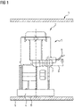
- figure 1 shows a portion of a fuel tank 1 shown in section with a fuel delivery unit arranged therein.
- the fuel delivery unit 2 has a holder 4 for a fuel pump 5 with a pre-filter 6 that is prestressed against the bottom 3 of the fuel tank 1 .
- Electrical connecting lines 9 for supplying the fuel pump 5 with electrical current are also routed radially away from the fuel pump 5 .
- the connecting piece 7 and the connecting lines 9 are arranged in an axial middle area of the fuel pump 5 .
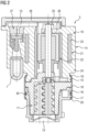
- FIG 2 shows a longitudinal section through the fuel pump 5 figure 1 .
- an electric motor 10 drives a pump stage 11 .
- the pump stage 11 draws in fuel via an intake port 12 and delivers it through the electric motor 10 via a channel 13 to the connection port 7.
- the electric motor 10 has a manufactured motor housing 14 with an edge 15 facing the pump stage 11.
- the pump stage 11 has a pump housing 16 with also an edge 17.
- a metal jacket 18 engages behind the edges with a roll 19, 20 and thus prestresses the pump housing 16 against the motor housing 14.
- the electric motor 10 has a stator 21 and a rotor 22 connected to the pump stage 11. Coils 23 or permanent magnets of the stator 11 are arranged within a section 24 made of plastic and overmoulded by the latter.
- the rotor 22 is mounted in the pump stage 11 and has a further bearing 25 in the end of the plastic section 24 of the motor housing 14 facing away from the pump stage 11. This bearing 25 is held by several support arms 26 of the motor housing 14. The fuel flows between the support arms 26 from the pump stage 11 to the connection piece 7.
- a check valve 27 is arranged in the channel 13 provided for guiding fuel.
- the channel 13 is closed by a cover 28 on a section 24 arranged in the side of the motor housing 14 facing away from the pump stage 11 .
- the cover 28 is sealingly connected to the section 24 of the motor housing 14 made of plastic.
- the sealing connection is produced, for example, by welding or by gluing.
- a sealing ring 30 embodied, for example, as an O-ring or O-ring seals the pump housing 16 radially with respect to the metal jacket 18 .
- the radial sealing of the pump housing 16 with respect to the metal jacket 18 achieves a floating centering of the pump stage.
- the rolling area of the metal jacket 18 on the pump stage 16 can be shifted towards the pressure side of the pump stage 16, so that the length of the metal jacket 18 can be further reduced.
- FIG 3 shows the fuel pump 5 in a plan view of the cover 28. It can be seen here that the connecting lines 9 are made of plastic in the section 24 of the motor housing 14 and are partially encapsulated by this. Connection contacts 29, which establish a conductive connection between fuel pump 5 and connecting lines 9, are also overmoulded by the plastic of section 24 of motor housing 14.
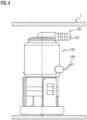
- FIG 4 shows a further embodiment of a fuel delivery unit 102 with a fuel pump 105.
- figure 5 shows the fuel pump 105 in a longitudinal section. This differs from the one from the Figures 1 to 3 characterized in that a fuel-carrying channel 113 is routed away through an end face of an electric motor 110 that faces away from a pump stage 111 .
- a cover 128 terminating the end face carries a connecting piece 107 for a fuel line and is sealed off from a section 124 of the motor housing 114 made of plastic.
- Connection lines 109 leading to the electric motor 110 lead radially into a section 104 of the motor housing 114 made of plastic.
- Connection contacts 129 of the fuel pump 105 are encapsulated by the plastic.
- the pump housing 116 is supported radially by means of a sealing ring 130 in relation to a metal jacket 118 .
- the sheet-metal jacket 118 prestresses an edge 115 of the motor housing 114 and an edge 117 of the pump housing 116 against one another by means of rolls 119, 120.
- the edge 115 of the motor housing 114 is arranged on the side facing the pump housing 116 as seen from the stator 121 .
- a rotor 122 is arranged in the pump stage 111 and in the plastic-made section 124 of the motor housing 114 .
- the pump stages 11, 111 are designed as screw pumps.
- the pump stages can also be designed as a side channel or as a peripheral pump.
- FIG figure 6 shows a longitudinal section through a further embodiment of a fuel pump 205. This differs from that in FIG figure 2 in that a connecting piece 207 for the in figure 1 shown flow line 8 is made in one piece with a stator 221 holding portion 224 of an electric motor 210.
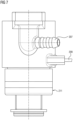
- FIG. 12 shows a side view of fuel pump 205.
- FIG figure 6 It can be seen here that connecting lines 209 leading to the stator 221 are arranged closer to a pump stage 211 than the connecting piece 207.
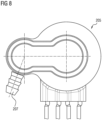
- figure 8 12 shows fuel pump 205 in a plan view figure 6 that the connecting piece 207 is angled relative to the axis of symmetry of the fuel pump 205. Otherwise, the embodiment of the fuel pump 205 according to Figures 6 to 8 essentially like those from the Figures 1 to 3 built up.
Landscapes
- Engineering & Computer Science (AREA)
- Chemical & Material Sciences (AREA)
- Combustion & Propulsion (AREA)
- Mechanical Engineering (AREA)
- General Engineering & Computer Science (AREA)
- Power Engineering (AREA)
- Structures Of Non-Positive Displacement Pumps (AREA)
- Motor Or Generator Frames (AREA)
Description
- Die Erfindung betrifft eine Kraftstoffpumpe mit einem Elektromotor und mit einer Pumpenstufe, mit einem Motorgehäuse des Elektromotors, mit einem Pumpengehäuse der Pumpenstufe und mit einem Ränder des Motorgehäuses und des Pumpengehäuses hintergreifenden Blechmantel, wobei das Motorgehäuse zur Halterung eines einen Rotor umschließenden Stators des Elektromotors ausgebildet ist, wobei das Motorgehäuse einen den Stator halternden Abschnitt aus Kunststoff hat und wobei, von dem Stator aus gesehen, der Rand des Motorgehäuses für den Blechmantel auf der dem Pumpengehäuse zugewandten Seite angeordnet ist.
- Solche Kraftstoffpumpen werden in heutigen Kraftfahrzeugen häufig eingesetzt und sind aus der Praxis bekannt. Bei der bekannten Kraftstoffpumpe sind der Elektromotor und die Pumpenstufe derart mit dem Blechmantel verrollt, dass sowohl der Elektromotor als auch die Pumpenstufe eingekapselt und dabei dichtend umschlossen sind. Eine Druckseitig ausgebildete Schnittstelle zum Elektromotor einerseits und eine saugseitige Anordnung einer axial wirkenden Dichtung oder Axialdichtung andererseits beeinflussen sich eine beim Verrollen des Blechmantels einstellende Verspannung der Pumpenstufe. Diese Verspannung erstreckt sich dabei über die gesamte Pumpenstufe und führt zu einer statisch über- oder unbestimmten Einbausituation der Pumpenstufe.
- Die Pumpenstufe der Kraftstoffpumpe kann als Peripheralpumpe, als Seitenkanalpumpe oder als Schraubenpumpe ausgebildet sein.
- Nachteilig bei der bekannten Kraftstoffpumpe ist jedoch, dass der Blechmantel ein sehr kostenintensives Bauteil darstellt. Zudem verschließt der Blechmantel den radialen Umfang des Elektromotors und der Pumpenstufe, so dass sämtliche Anschlüsse der Kraftstoffpumpe axial weggeführt sind. Die bekannte Kraftstoffpumpe weist daher besonders große axiale Abmessungen auf. Große axiale Abmessungen sind jedoch sehr störend, wenn die Kraftstoffpumpe innerhalb eines Kraftstoffbehälters angeordnet werden soll.
- Die Druckschrift
DE 10 2005 015 014 A1 offenbart eine Kraftstoffpumpe mit einem Elektromotor, der eine Pumpenstufe antreibt, durch die Kraftstoff förderbar ist. Der Elektromotor weist einen Stator und einen Rotor auf. Das Motorgehäuse des Elektromotors ist über einen Blechmantel mit einem Pumpenstufengehäuse der Pumpenstufe verbunden, indem der Blechmantel mit dem Motorgehäuse vergossen wird. - Die Druckschrift
JP 5338733 B2 - Der Erfindung liegt das Problem zugrunde, eine Kraftstoffpumpe der eingangs genannten Art so weiter zu bilden, dass sie besonders kostengünstig zu fertigen ist und besonders niedrige Abmessungen aufweist.
- Dieses Problem wird erfindungsgemäß dadurch gelöst, dass der Blechmantel die Ränder mit jeweils einer Verrollung hintergreift, derart, dass das Pumpengehäuse gegen das Motorgehäuse vorgespannt ist.
- Durch diese Gestaltung erstreckt sich der Blechmantel ausschließlich von dem dem Pumpengehäuse zugewandten Rand des Motorgehäuses bis über das Pumpengehäuse. Der überwiegende Bereich des Elektromotors ist dank der Erfindung nicht von dem Blechmantel umfasst. Damit lässt sich der Blechmantel besonders kurz gestalten. Die erfindungsgemäße Kraftstoffpumpe lässt sich daher besonders kostengünstig fertigen. Weiterhin lassen sich Anschlüsse von dem aus Kunststoff gefertigten Abschnitt des Elektromotors radial abführen. Dies trägt zu besonders geringen Abmessungen der Kraftstoffpumpe bei.
- Die Kraftstoffpumpe lässt sich gemäß einer anderen vorteilhaften Weiterbildung der Erfindung besonders kostengünstig fertigen, wenn die Höhe des Blechmantels maximal 50 % der Summe der Höhen des Pumpengehäuses und des Motorgehäuses beträgt.
- Bei bekannten Kraftstoffpumpen sind Anschlusskontakte des Stators in der Regel von Kraftstoff umströmt. Zur Vermeidung von Korrosion sind sehr kostenintensive Abdichtungen und Beschichtungen der Anschlusskontakte bekannt. Kostenintensive Abdichtungen von Anschlusskontakten des Elektromotors lassen sich gemäß einer anderen vorteilhaften Weiterbildung der Erfindung einfach vermeiden, wenn Anschlusskontakte des Stators von dem Kunststoff des Motorgehäuses dichtend eingeschlossen sind. Vorzugsweise ist der aus Kunststoff gefertigte Abschnitt des Motorgehäuses besonders kostengünstig im Spritzgussverfahren gefertigt.
- Zur Verringerung der axialen Bauhöhe der Kraftstoffpumpe trägt es gemäß einer anderen vorteilhaften Weiterbildung der Erfindung bei, wenn zu dem Elektromotor führende Anschlussleitungen radial in den aus Kunststoff gefertigten Abschnitt des Motorgehäuses geführt sind.
- Die Anzahl der Bauteile der Kraftstoffpumpe lassen sich gemäß einer anderen vorteilhaften Weiterbildung der Erfindung besonders gering halten, wenn der aus Kunststoff gefertigte Abschnitt des Motorgehäuses einen Anschlussstutzen für eine Kraftstoffleitung hat. Durch diese Gestaltung wird ein separat zu montierender Deckel für den Anschlussstutzen vermieden.
- Die Kraftstoffpumpe weist gemäß einer anderen vorteilhaften Weiterbildung der Erfindung eine besonders geringe Bauhöhe auf, wenn der Anschlussstutzen radial von dem Motorgehäuse weg geführt ist. Durch diese Gestaltung lässt sich die Kraftstoffpumpe auch in niedrigen Kraftstoffbehältern anordnen.
- Zur weiteren Verringerung der axialen Abmessungen der Kraftstoffpumpe trägt es gemäß einer anderen vorteilhaften Weiterbildung der Erfindung bei, wenn der Anschlussstutzen auf der axialen Höhe des Stators angeordnet ist.
- Kanäle zur Führung von Kraftstoff durch die Kraftstoffpumpe lassen sich gemäß einer anderen vorteilhaften Weiterbildung der Erfindung besonders einfach fertigen, wenn ein zu einem dem Anschlussstutzen führender Deckel eines Kanals auf dem aus Kunststoff gefertigten Abschnitt des Motorgehäuses abgedichtet ist. Die Abdichtung erfolgt vorzugsweise im Schweißverfahren, beispielsweise durch Spiegelschweißen, oder durch Verklebung.
- Der aus Kunststoff gefertigte Abschnitt des Motorgehäuses lässt sich gemäß einer anderen vorteilhaften Weiterbildung der Erfindung in einer besonders einfachen Werkzeugform fertigen, wenn ein Abschnitt des Kraftstoff führenden Kanals parallel zur Achse des Rotors von der dem Pumpengehäuse abgewandten Ende in das Motorgehäuse geführt ist.
- Eine separat zu montierende Lagerung des Rotors des Elektromotors lässt sich gemäß einer anderen vorteilhaften Weiterbildung der Erfindung vermeiden, wenn der Rotor des Elektromotors mit einem Ende an dem Pumpengehäuse und mit dem anderem Ende in dem aus Kunststoff gefertigten Abschnitt des Motorgehäuses gelagert ist.
- Die Montage der Kraftstoffpumpe gestaltet sich gemäß einer anderen vorteilhaften Weiterbildung der Erfindung besonders einfach, wenn der den Stator halternde Abschnitt des Motorgehäuses eine dem Pumpengehäuse zugewandte offene Seite zur Einführung des Rotors hat. Durch diese Gestaltung lässt sich der Elektromotor von einer Seite, nämlich der der Pumpenstufe zugewandten Seite montieren.
- Die Kraftstoffpumpe gestaltet sich gemäß einer anderen vorteilhaften Weiterbildung der Erfindung konstruktiv besonders einfach, wenn der aus Kunststoff gefertigte Abschnitt Stützarme zur Abstützung der Lagerung des Rotors hat und dass ein Kanal zur Führung des Kraftstoffs zwischen den Stützarmen hindurchführt.
- Die Abdichtung der Kraftstoffpumpe gestaltet sich gemäß einer anderen vorteilhaften Weiterbildung der Erfindung konstruktiv besonders einfach, wenn zwischen dem Pumpengehäuse und dem Blechmantel ein radial dichtender Dichtring angeordnet ist. Der Dichtring kann als Elastomer O-Ring ausgebildet sein. Alternativ dazu kann der Dichtring auch als Rundschnurrring ausgebildet sein. Solche Rundschnurringe werden im Extrusionsverfahren als Schnur gefertigt und auf Stoß miteinander durch Klebung oder Vulkanisierung verbunden.
- Die Erfindung lässt zahlreiche Ausführungsformen zu. Zur weiteren Verdeutlichung ihres Grundprinzips sind mehrere davon in der Zeichnung dargestellt und werden nachfolgend beschrieben. Diese zeigt in
- Fig. 1
- eine in einem Kraftstoffbehälter montierte Kraftstofffördereinheit,
- Fig. 2
- einen Längsschnitt durch eine Kraftstoffpumpe der Kraftstofffördereinheit aus
Figur 1 , - Fig. 3
- eine Draufsicht auf die Kraftstoffpumpe aus
Figur 2 , - Fig. 4
- eine weitere Ausführungsform einer in einem Kraftstoffbehälter montierte Kraftstofffördereinheit,
- Fig. 5
- einen Längsschnitt durch eine Kraftstoffpumpe der Kraftstofffördereinheit,
- Fig. 6
- einen Längsschnitt durch eine weitere Ausführungsform der Kraftstoffpumpe,
- Fig. 7
- eine Seitenansicht der Kraftstoffpumpe aus
Figur 6 , - Fig. 8
- eine Draufsicht auf die Kraftstoffpumpe aus
Figur 6 . -
Figur 1 zeigt einen Teilbereich eines geschnitten dargestellten Kraftstoffbehälters 1 mit einer darin angeordneten Kraftstofffördereinheit. Die Kraftstofffördereinheit 2 hat einen gegen den Boden 3 des Kraftstoffbehälters 1 vorgespannten Halter 4 für eine Kraftstoffpumpe 5 mit einem Vorfilter 6. Ein Anschlussstutzen 7 zur Verbindung mit einer Kraftstoff abführenden Kraftstoffleitung 8 ist radial von der Kraftstoffpumpe 5 weg geführt. Elektrische Anschlussleitungen 9 zur Versorgung der Kraftstoffpumpe 5 mit elektrischem Strom sind ebenfalls radial von der Kraftstoffpumpe 5 weggeführt. Der Anschlussstutzen 7 und die Anschlussleitungen 9 sind in einem axialen mittleren Bereich der Kraftstoffpumpe 5 angeordnet. -
Figur 2 zeigt einen Längsschnitt durch die Kraftstoffpumpe 5 ausFigur 1 . Hierbei ist zu erkennen, dass ein Elektromotor 10 eine Pumpenstufe 11 antreibt. Die Pumpenstufe 11 saugt Kraftstoff über einen Ansaugstutzen 12 an und fördert diesen durch den Elektromotor 10 über einen Kanal 13 zu dem Anschlussstutzen 7. Der Elektromotor 10 hat ein gefertigtes Motorgehäuse 14 mit einem der Pumpenstufe 11 zugewandten Rand 15. Die Pumpenstufe 11 hat ein Pumpengehäuse 16 mit ebenfalls einem Rand 17. Ein Blechmantel 18 hintergreift die Ränder mit jeweils einer Verrollung 19, 20 und spannt damit das Pumpengehäuse 16 gegen das Motorgehäuse 14 vor. - Der Elektromotor 10 hat einen Stator 21 und einen mit der Pumpenstufe 11 verbundenen Rotor 22. Spulen 23 oder Permanentmagnete des Stators 11 sind innerhalb eines aus Kunststoff gefertigten Abschnitts 24 angeordnet und von diesem umspritzt. Der Rotor 22 ist in der Pumpenstufe 11 gelagert und hat eine weitere Lagerung 25 in dem von der Pumpenstufe 11 abgewandten Ende des aus Kunststoff gefertigten Abschnitts 24 des Motorgehäuses 14. Diese Lagerung 25 ist von mehreren Stützarmen 26 des Motorgehäuses 14 gehalten. Zwischen den Stützarmen 26 strömt der Kraftstoff von der Pumpenstufe 11 zu dem Anschlussstutzen 7.
- In dem zur Führung von Kraftstoff vorgesehenen Kanal 13 ist ein Rückschlagventil 27 angeordnet. Der Kanal 13 ist an einem in dem von der Pumpenstufe 11 abgewandten Seite des Motorgehäuses 14 angeordneten Abschnitt 24 von einem Deckel 28 verschlossen. Der Deckel 28 ist dichtend mit dem aus Kunststoff gefertigten Abschnitt 24 des Motorgehäuses 14 verbunden. Die dichtende Verbindung ist beispielsweise im Schweißverfahren oder durch Verklebung erzeugt. Ein beispielsweise als O-Ring oder Rundschnurring ausgebildeter Dichtring 30 dichtet das Pumpengehäuse 16 radial gegenüber dem Blechmantel 18 ab.
- Die radiale Abdichtung des Pumpengehäuses 16 gegenüber dem Blechmantel 18 wird eine schwimmende Zentrierung der Pumpenstufe erreicht. Zudem kann der Verrollbereich des Blechmantels 18 an der Pumpenstufe 16 hin zur Druckseite der Pumpenstufe 16 verlagert werden, so dass sich die Länge des Blechmantels 18 weiter reduzieren lässt.
-
Figur 3 zeigt die Kraftstoffpumpe 5 in einer Draufsicht auf den Deckel 28. Hierbei ist zu erkennen, dass die Anschlussleitungen 9 in den aus Kunststoff gefertigten Abschnitt 24 des Motorgehäuses 14 geführt und von diesem teilweise umspritzt sind. Ebenso sind Anschlusskontakte 29, welche eine leitende Verbindung der Kraftstoffpumpe 5 mit den Anschlussleitungen 9 herstellen, von dem Kunststoff des Abschnitts 24 des Motorgehäuses 14 umspritzt. -
Figur 4 zeigt eine weitere Ausführungsform einer Kraftstofffördereinheit 102 mit einer Kraftstoffpumpe 105.Figur 5 zeigt die Kraftstoffpumpe 105 in einem Längsschnitt. Diese unterscheidet sich von der aus denFiguren 1 bis 3 dadurch, ein Kraftstoff führender Kanal 113 durch eine einer Pumpenstufe 111 abgewandten Stirnseite eines Elektromotors 110 weg geführt ist. Ein die Stirnseite abschließender Deckel 128 trägt einen Anschlussstutzen 107 für eine Kraftstoffleitung und ist gegenüber einem aus Kunststoff gefertigten Abschnitt 124 des Motorgehäuses 114 abgedichtet. Zu dem Elektromotor 110 führende Anschlussleitungen 109 führen radial in einen aus Kunststoff gefertigten Abschnitt 104 des Motorgehäuses 114 hinein. Anschlusskontakte 129 der Kraftstoffpumpe 105 sind von dem Kunststoff umspritzt. Das Pumpengehäuse 116 ist radial mittels eines Dichtrings 130 gegenüber einem Blechmantel 118 abgestützt. Der Blechmantel 118 spannt durch Verrollungen 119, 120 einen Rand 115 des Motorgehäuses 114 und einen Rand 117 des Pumpengehäuses 116 gegeneinander vor. Der Rand 115 des Motorgehäuses 114 ist von dem Stator 121 aus gesehen auf der dem Pumpengehäuse 116 zugewandten Seite angeordnet. Ein Rotor 122 ist in der Pumpenstufe 111 und in dem aus Kunststoff gefertigten Abschnitt 124 des Motorgehäuses 114 angeordnet. - Bei den Kraftstoffpumpen 5, 105 aus den
Figuren 1 bis 5 sind die Pumpenstufen 11, 111 als Schraubenpumpen ausgebildet. Zwei Schraubenspindeln der Pumpenstufen 11, 111 bilden in Verbindung mit dem Pumpengehäuse 16, 116 Förderkammern, welche sich infolge er Drehung der Schraubenspindeln, von einer Saugseite zu einer Druckseite der Pumpenstufe 11, 111 bewegen. In einer alternativen, nicht dargestellten Ausführungsform können die Pumpenstufen auch als Seitenkanal oder als Peripheralpumpe ausgebildet sein. -
Figur 6 zeigt einen Längsschnitt durch eine weitere Ausführungsform einer Kraftstoffpumpe 205. Diese unterscheidet sich von der ausFigur 2 dadurch, dass ein Anschlussstutzen 207 für die inFigur 1 dargestellte Vorlaufleitung 8 einstückig mit einem einen Stator 221 halternden Abschnitt 224 eines Elektromotors 210 gefertigt ist. -
Figur 7 zeigt eine Seitenansicht der Kraftstoffpumpe 205 ausFigur 6 . Hierbei ist zu erkennen, dass zu dem Stator 221 führende Anschlussleitungen 209 näher an einer Pumpenstufe 211 angeordnet sind als der Anschlussstutzen 207. -
Figur 8 zeigt in einer Draufsicht die Kraftstoffpumpe 205 ausFigur 6 , dass der Anschlussstutzen 207 gegenüber Symmetrieachsen der Kraftstoffpumpe 205 abgewinkelt ist. Ansonsten ist die Ausführungsform der Kraftstoffpumpe 205 nach denFiguren 6 bis 8 im Wesentlichen wie die aus denFiguren 1 bis 3 aufgebaut.
Claims (13)
- Kraftstoffpumpe (5, 105, 205) mit einem Elektromotor (10, 110, 210) und mit einer Pumpenstufe (11, 111, 211), mit einem Motorgehäuse (14, 114) des Elektromotors (10, 110, 210), mit einem Pumpengehäuse (16, 116) der Pumpenstufe (11, 111, 211) und mit einem Ränder (15, 17, 115, 117) des Motorgehäuses (14, 114) und des Pumpengehäuses (16, 116) hintergreifenden Blechmantel (18, 118), wobei das Motorgehäuse (14, 114) zur Halterung eines einen Rotor (22, 222) umschließenden Stators (21, 121, 221) des Elektromotors (10, 110, 210) ausgebildet ist, wobei das Motorgehäuse (14, 114) einen den Stator (21, 121, 221) halternden Abschnitt (24, 124, 224) aus Kunststoff hat, wobei, von dem Stator (24, 124, 224) aus gesehen, der Rand (15, 115) des Motorgehäuses (14, 114) für den Blechmantel (18) auf der dem Pumpengehäuse (16, 116) zugewandten Seite angeordnet ist, dadurch gekennzeichnet, dass der Blechmantel (18) die Ränder (15, 17, 115, 117) mit jeweils einer Verrollung (19, 20) hintergreift, derart, dass das Pumpengehäuse (16, 116) gegen das Motorgehäuse (14, 114) vorspannt ist.
- Kraftstoffpumpe nach Anspruch 1, dadurch gekennzeichnet, dass die Höhe des Blechmantels (18, 118) maximal 50 % der Summe der Höhen des Pumpengehäuses (16, 116) und des Motorgehäuses (14, 114) beträgt.
- Kraftstoffpumpe nach Anspruch 1 oder 2, dadurch gekennzeichnet, dass Anschlusskontakte (29, 129) des Stators (21, 121, 221) von dem Kunststoff des Motorgehäuses (14, 114) dichtend eingeschlossen sind.
- Kraftstoffpumpe nach einem der Ansprüche 1 bis 3, dadurch gekennzeichnet, dass zu dem Elektromotor (10, 110) führende Anschlussleitungen (9, 109, 209) radial in den aus Kunststoff gefertigten Abschnitt (24, 124, 224) des Motorgehäuses (14, 114) geführt sind.
- Kraftstoffpumpe nach einem der Ansprüche 1 bis 4, dadurch gekennzeichnet, dass der aus Kunststoff gefertigte Abschnitt (24, 124, 224) des Motorgehäuses (14, 114) einen Anschlussstutzen (7, 107, 207) für eine Kraftstoffleitung (8, 108) hat.
- Kraftstoffpumpe nach Anspruch 5, dadurch gekennzeichnet, dass der Anschlussstutzen (7, 107, 207) radial von dem Motorgehäuse weggeführt ist.
- Kraftstoffpumpe nach Anspruch 5 oder 6, dadurch gekennzeichnet, dass der Anschlussstutzen (7, 207) auf der axialen Höhe des Stators (21, 221) angeordnet ist.
- Kraftstoffpumpe nach einem der Ansprüche 5 bis 7, dadurch gekennzeichnet, dass ein zu einem dem Anschlussstutzen (7, 107, 207) führender Deckel (28, 128) eines Kanals (13, 113) auf dem aus Kunststoff gefertigten Abschnitt (24, 124, 224) des Motorgehäuses (14, 114) abgedichtet ist.
- Kraftstoffpumpe nach Anspruch 8, dadurch gekennzeichnet, dass ein Abschnitt des Kraftstoff führenden Kanals (13) parallel zur Achse des Rotors (22) von der dem Pumpengehäuse (16) abgewandten Ende in das Motorgehäuse (14) geführt ist.
- Kraftstoffpumpe nach einem der Ansprüche 1 bis 9, dadurch gekennzeichnet, dass der Rotor (22, 122) des Elektromotors (10, 110) mit einem Ende an dem Pumpengehäuse (16, 116) und mit dem anderem Ende in dem aus Kunststoff gefertigten Abschnitt (24, 124, 224) des Motorgehäuses (14, 114) gelagert ist.
- Kraftstoffpumpe nach Anspruch 10, dadurch gekennzeichnet, dass der den Stator (21, 121, 221) halternde Abschnitt (24, 124, 224) des Motorgehäuses (14, 114) eine dem Pumpengehäuse (16, 116) zugewandte offene Seite zur Einführung des Rotors (22, 122) hat.
- Kraftstoffpumpe nach Anspruch 10 oder 11, dadurch gekennzeichnet, dass der aus Kunststoff gefertigte Abschnitt (24, 124, 224) Stützarme (26) zur Abstützung der Lagerung (25) des Rotors (22, 122) hat und dass der Kanal (13, 113) zur Führung des Kraftstoffs zwischen den Stützarmen (26) hindurchführt.
- Kraftstoffpumpe nach einem der Ansprüche 1 bis 12, dadurch gekennzeichnet, dass zwischen dem Pumpengehäuse (16, 116) und dem Blechmantel (18, 118) ein radial dichtender Dichtring (30, 130) angeordnet ist.
Applications Claiming Priority (2)
| Application Number | Priority Date | Filing Date | Title |
|---|---|---|---|
| DE102016220638.9A DE102016220638A1 (de) | 2016-10-20 | 2016-10-20 | Kraftstoffpumpe |
| PCT/EP2017/075278 WO2018073009A1 (de) | 2016-10-20 | 2017-10-05 | Kraftstoffpumpe |
Publications (2)
| Publication Number | Publication Date |
|---|---|
| EP3529879A1 EP3529879A1 (de) | 2019-08-28 |
| EP3529879B1 true EP3529879B1 (de) | 2023-04-05 |
Family
ID=60043188
Family Applications (1)
| Application Number | Title | Priority Date | Filing Date |
|---|---|---|---|
| EP17781080.1A Active EP3529879B1 (de) | 2016-10-20 | 2017-10-05 | Kraftstoffpumpe |
Country Status (6)
| Country | Link |
|---|---|
| US (1) | US20210285409A1 (de) |
| EP (1) | EP3529879B1 (de) |
| KR (1) | KR102240468B1 (de) |
| CN (1) | CN109983664A (de) |
| DE (1) | DE102016220638A1 (de) |
| WO (1) | WO2018073009A1 (de) |
Family Cites Families (16)
| Publication number | Priority date | Publication date | Assignee | Title |
|---|---|---|---|---|
| JPS5338733B2 (de) * | 1974-05-11 | 1978-10-17 | ||
| US4447192A (en) * | 1980-02-19 | 1984-05-08 | Walbro Corporation | Self-contained rotary fuel pump |
| US4619591A (en) | 1985-11-11 | 1986-10-28 | Mitsubishi Denki Kabushiki Kaisha | In-tank type fuel pump |
| US5013222A (en) * | 1990-04-19 | 1991-05-07 | General Motors Corporation | Fuel pump for motor vehicle |
| JP4613596B2 (ja) * | 2004-04-02 | 2011-01-19 | 株式会社デンソー | 燃料供給装置 |
| DE102005015014A1 (de) * | 2004-04-02 | 2005-11-03 | Denso Corp., Kariya | Brennstoffpumpe, Brennstoffzufuhrvorrichtung unter Verwendung der Brennstoffpumpe und Verfahren zur Herstellung der Brennstoffpumpe |
| US7365458B2 (en) * | 2005-03-31 | 2008-04-29 | Nidec Shibaura Corporation | Brushless DC motor with molded resin housing |
| JP5338733B2 (ja) * | 2009-11-05 | 2013-11-13 | 三菱電機株式会社 | 燃料供給装置 |
| CN102052217B (zh) * | 2009-11-05 | 2013-03-06 | 三菱电机株式会社 | 燃料供给装置 |
| US20130055771A1 (en) * | 2010-07-21 | 2013-03-07 | Panasonic Corporation | Brushless motor for washing machine and drum-type washing machine provided with same |
| US20130042655A1 (en) * | 2010-07-21 | 2013-02-21 | Panasonic Corporation | Brushless motor for washing machine, drum-type washing machine provided with same and manufacturing method of brushless motor for washing machine |
| JP2012031808A (ja) * | 2010-08-02 | 2012-02-16 | Denso Corp | 燃料ポンプ |
| JP5818476B2 (ja) * | 2011-03-25 | 2015-11-18 | 三菱電機株式会社 | 燃料供給装置 |
| JP2013066314A (ja) * | 2011-09-19 | 2013-04-11 | Nippon Densan Corp | モータおよびモータの製造方法 |
| JP5672510B2 (ja) * | 2012-06-01 | 2015-02-18 | 株式会社デンソー | ブラシレスモータ、および、それを用いた燃料ポンプ |
| JP6444653B2 (ja) * | 2014-08-18 | 2018-12-26 | 愛三工業株式会社 | ステータ及び電動ポンプ |
-
2016
- 2016-10-20 DE DE102016220638.9A patent/DE102016220638A1/de not_active Withdrawn
-
2017
- 2017-10-05 US US16/343,302 patent/US20210285409A1/en not_active Abandoned
- 2017-10-05 WO PCT/EP2017/075278 patent/WO2018073009A1/de not_active Ceased
- 2017-10-05 EP EP17781080.1A patent/EP3529879B1/de active Active
- 2017-10-05 KR KR1020197014316A patent/KR102240468B1/ko active Active
- 2017-10-05 CN CN201780063415.5A patent/CN109983664A/zh active Pending
Also Published As
| Publication number | Publication date |
|---|---|
| EP3529879A1 (de) | 2019-08-28 |
| KR102240468B1 (ko) | 2021-04-14 |
| WO2018073009A1 (de) | 2018-04-26 |
| KR20190065434A (ko) | 2019-06-11 |
| US20210285409A1 (en) | 2021-09-16 |
| CN109983664A (zh) | 2019-07-05 |
| DE102016220638A1 (de) | 2018-04-26 |
Similar Documents
| Publication | Publication Date | Title |
|---|---|---|
| DE102012111150A1 (de) | Elektrische Wasserpumpe | |
| WO2018073008A1 (de) | Kraftstoffpumpe | |
| DE10140613A1 (de) | Naßläuferpumpe | |
| DE102017214264A1 (de) | Pumpengehäuse für eine gerotor-pumpe und gerotor-pumpe | |
| WO2019072887A1 (de) | Kraftstoffpumpe und kraftstofffördereinheit | |
| EP0982491B1 (de) | Fördereinheit | |
| DE102021114571A1 (de) | Spaltrohrmotor | |
| EP3379085B1 (de) | Umspritzter und ausgewuchteter aussenläufer-rotor einer pumpe | |
| DE102011077777B3 (de) | Tauchpumpe und Verfahren zum Zusammenbau einer Tauchpumpe | |
| EP3529879B1 (de) | Kraftstoffpumpe | |
| WO2019072895A1 (de) | Kraftstoffpumpe und kraftstofffördereinheit | |
| EP2228538A1 (de) | Mehrstufiges Kreiselpumpenaggregat | |
| DE102010005963A1 (de) | Rotor mit umspritzter Hülse | |
| DE102007025510A1 (de) | Kraftstoffpumpe | |
| DE112016005804T5 (de) | Kraftstoffpumpeneinheit | |
| EP3055568A1 (de) | Pumpe | |
| DE102010041240A1 (de) | Pumpe mit Elektromotor | |
| DE19906884A1 (de) | Elektromotor | |
| DE102010041244A1 (de) | Pumpe mit Elektromotor | |
| EP2990651A1 (de) | Pumpengehäuse | |
| DE102010041237A1 (de) | Pumpe mit Elektromotor | |
| DE102009047910B4 (de) | Läufereinheit für einen Elektromotor und Wasserpumpe mit Elektromotor | |
| DE102017012219B4 (de) | Kraftstoffpumpe und Kraftstofffördereinheit | |
| DE102018110174A1 (de) | Elektromotor und lagerschild für einen elektromotor | |
| DE102016211596A1 (de) | Förderaggregat |
Legal Events
| Date | Code | Title | Description |
|---|---|---|---|
| STAA | Information on the status of an ep patent application or granted ep patent |
Free format text: STATUS: UNKNOWN |
|
| STAA | Information on the status of an ep patent application or granted ep patent |
Free format text: STATUS: THE INTERNATIONAL PUBLICATION HAS BEEN MADE |
|
| PUAI | Public reference made under article 153(3) epc to a published international application that has entered the european phase |
Free format text: ORIGINAL CODE: 0009012 |
|
| STAA | Information on the status of an ep patent application or granted ep patent |
Free format text: STATUS: REQUEST FOR EXAMINATION WAS MADE |
|
| 17P | Request for examination filed |
Effective date: 20190520 |
|
| AK | Designated contracting states |
Kind code of ref document: A1 Designated state(s): AL AT BE BG CH CY CZ DE DK EE ES FI FR GB GR HR HU IE IS IT LI LT LU LV MC MK MT NL NO PL PT RO RS SE SI SK SM TR |
|
| AX | Request for extension of the european patent |
Extension state: BA ME |
|
| RAP1 | Party data changed (applicant data changed or rights of an application transferred) |
Owner name: VITESCO TECHNOLOGIES GMBH |
|
| DAV | Request for validation of the european patent (deleted) | ||
| DAX | Request for extension of the european patent (deleted) | ||
| RAP1 | Party data changed (applicant data changed or rights of an application transferred) |
Owner name: VITESCO TECHNOLOGIES GMBH |
|
| STAA | Information on the status of an ep patent application or granted ep patent |
Free format text: STATUS: EXAMINATION IS IN PROGRESS |
|
| 17Q | First examination report despatched |
Effective date: 20210121 |
|
| RAP3 | Party data changed (applicant data changed or rights of an application transferred) |
Owner name: VITESCO TECHNOLOGIES GMBH |
|
| REG | Reference to a national code |
Ref country code: DE Ref legal event code: R079 Ref document number: 502017014601 Country of ref document: DE Free format text: PREVIOUS MAIN CLASS: H02K0005120000 Ipc: H02K0005132000 |
|
| GRAP | Despatch of communication of intention to grant a patent |
Free format text: ORIGINAL CODE: EPIDOSNIGR1 |
|
| STAA | Information on the status of an ep patent application or granted ep patent |
Free format text: STATUS: GRANT OF PATENT IS INTENDED |
|
| RIC1 | Information provided on ipc code assigned before grant |
Ipc: F02M 37/10 20060101ALI20221024BHEP Ipc: F02M 37/00 20060101ALI20221024BHEP Ipc: H02K 5/132 20060101AFI20221024BHEP |
|
| INTG | Intention to grant announced |
Effective date: 20221111 |
|
| GRAS | Grant fee paid |
Free format text: ORIGINAL CODE: EPIDOSNIGR3 |
|
| GRAA | (expected) grant |
Free format text: ORIGINAL CODE: 0009210 |
|
| STAA | Information on the status of an ep patent application or granted ep patent |
Free format text: STATUS: THE PATENT HAS BEEN GRANTED |
|
| AK | Designated contracting states |
Kind code of ref document: B1 Designated state(s): AL AT BE BG CH CY CZ DE DK EE ES FI FR GB GR HR HU IE IS IT LI LT LU LV MC MK MT NL NO PL PT RO RS SE SI SK SM TR |
|
| REG | Reference to a national code |
Ref country code: GB Ref legal event code: FG4D Free format text: NOT ENGLISH |
|
| REG | Reference to a national code |
Ref country code: DE Ref legal event code: R096 Ref document number: 502017014601 Country of ref document: DE |
|
| REG | Reference to a national code |
Ref country code: CH Ref legal event code: EP |
|
| REG | Reference to a national code |
Ref country code: AT Ref legal event code: REF Ref document number: 1559000 Country of ref document: AT Kind code of ref document: T Effective date: 20230415 |
|
| REG | Reference to a national code |
Ref country code: IE Ref legal event code: FG4D Free format text: LANGUAGE OF EP DOCUMENT: GERMAN |
|
| P01 | Opt-out of the competence of the unified patent court (upc) registered |
Effective date: 20230530 |
|
| REG | Reference to a national code |
Ref country code: LT Ref legal event code: MG9D |
|
| REG | Reference to a national code |
Ref country code: NL Ref legal event code: MP Effective date: 20230405 |
|
| PG25 | Lapsed in a contracting state [announced via postgrant information from national office to epo] |
Ref country code: NL Free format text: LAPSE BECAUSE OF FAILURE TO SUBMIT A TRANSLATION OF THE DESCRIPTION OR TO PAY THE FEE WITHIN THE PRESCRIBED TIME-LIMIT Effective date: 20230405 |
|
| PG25 | Lapsed in a contracting state [announced via postgrant information from national office to epo] |
Ref country code: SE Free format text: LAPSE BECAUSE OF FAILURE TO SUBMIT A TRANSLATION OF THE DESCRIPTION OR TO PAY THE FEE WITHIN THE PRESCRIBED TIME-LIMIT Effective date: 20230405 Ref country code: PT Free format text: LAPSE BECAUSE OF FAILURE TO SUBMIT A TRANSLATION OF THE DESCRIPTION OR TO PAY THE FEE WITHIN THE PRESCRIBED TIME-LIMIT Effective date: 20230807 Ref country code: NO Free format text: LAPSE BECAUSE OF FAILURE TO SUBMIT A TRANSLATION OF THE DESCRIPTION OR TO PAY THE FEE WITHIN THE PRESCRIBED TIME-LIMIT Effective date: 20230705 Ref country code: ES Free format text: LAPSE BECAUSE OF FAILURE TO SUBMIT A TRANSLATION OF THE DESCRIPTION OR TO PAY THE FEE WITHIN THE PRESCRIBED TIME-LIMIT Effective date: 20230405 |
|
| PG25 | Lapsed in a contracting state [announced via postgrant information from national office to epo] |
Ref country code: RS Free format text: LAPSE BECAUSE OF FAILURE TO SUBMIT A TRANSLATION OF THE DESCRIPTION OR TO PAY THE FEE WITHIN THE PRESCRIBED TIME-LIMIT Effective date: 20230405 Ref country code: PL Free format text: LAPSE BECAUSE OF FAILURE TO SUBMIT A TRANSLATION OF THE DESCRIPTION OR TO PAY THE FEE WITHIN THE PRESCRIBED TIME-LIMIT Effective date: 20230405 Ref country code: LV Free format text: LAPSE BECAUSE OF FAILURE TO SUBMIT A TRANSLATION OF THE DESCRIPTION OR TO PAY THE FEE WITHIN THE PRESCRIBED TIME-LIMIT Effective date: 20230405 Ref country code: LT Free format text: LAPSE BECAUSE OF FAILURE TO SUBMIT A TRANSLATION OF THE DESCRIPTION OR TO PAY THE FEE WITHIN THE PRESCRIBED TIME-LIMIT Effective date: 20230405 Ref country code: IS Free format text: LAPSE BECAUSE OF FAILURE TO SUBMIT A TRANSLATION OF THE DESCRIPTION OR TO PAY THE FEE WITHIN THE PRESCRIBED TIME-LIMIT Effective date: 20230805 Ref country code: HR Free format text: LAPSE BECAUSE OF FAILURE TO SUBMIT A TRANSLATION OF THE DESCRIPTION OR TO PAY THE FEE WITHIN THE PRESCRIBED TIME-LIMIT Effective date: 20230405 Ref country code: GR Free format text: LAPSE BECAUSE OF FAILURE TO SUBMIT A TRANSLATION OF THE DESCRIPTION OR TO PAY THE FEE WITHIN THE PRESCRIBED TIME-LIMIT Effective date: 20230706 Ref country code: AL Free format text: LAPSE BECAUSE OF FAILURE TO SUBMIT A TRANSLATION OF THE DESCRIPTION OR TO PAY THE FEE WITHIN THE PRESCRIBED TIME-LIMIT Effective date: 20230405 |
|
| PG25 | Lapsed in a contracting state [announced via postgrant information from national office to epo] |
Ref country code: FI Free format text: LAPSE BECAUSE OF FAILURE TO SUBMIT A TRANSLATION OF THE DESCRIPTION OR TO PAY THE FEE WITHIN THE PRESCRIBED TIME-LIMIT Effective date: 20230405 |
|
| REG | Reference to a national code |
Ref country code: DE Ref legal event code: R097 Ref document number: 502017014601 Country of ref document: DE |
|
| PG25 | Lapsed in a contracting state [announced via postgrant information from national office to epo] |
Ref country code: SK Free format text: LAPSE BECAUSE OF FAILURE TO SUBMIT A TRANSLATION OF THE DESCRIPTION OR TO PAY THE FEE WITHIN THE PRESCRIBED TIME-LIMIT Effective date: 20230405 |
|
| PG25 | Lapsed in a contracting state [announced via postgrant information from national office to epo] |
Ref country code: SM Free format text: LAPSE BECAUSE OF FAILURE TO SUBMIT A TRANSLATION OF THE DESCRIPTION OR TO PAY THE FEE WITHIN THE PRESCRIBED TIME-LIMIT Effective date: 20230405 Ref country code: SK Free format text: LAPSE BECAUSE OF FAILURE TO SUBMIT A TRANSLATION OF THE DESCRIPTION OR TO PAY THE FEE WITHIN THE PRESCRIBED TIME-LIMIT Effective date: 20230405 Ref country code: RO Free format text: LAPSE BECAUSE OF FAILURE TO SUBMIT A TRANSLATION OF THE DESCRIPTION OR TO PAY THE FEE WITHIN THE PRESCRIBED TIME-LIMIT Effective date: 20230405 Ref country code: EE Free format text: LAPSE BECAUSE OF FAILURE TO SUBMIT A TRANSLATION OF THE DESCRIPTION OR TO PAY THE FEE WITHIN THE PRESCRIBED TIME-LIMIT Effective date: 20230405 Ref country code: DK Free format text: LAPSE BECAUSE OF FAILURE TO SUBMIT A TRANSLATION OF THE DESCRIPTION OR TO PAY THE FEE WITHIN THE PRESCRIBED TIME-LIMIT Effective date: 20230405 Ref country code: CZ Free format text: LAPSE BECAUSE OF FAILURE TO SUBMIT A TRANSLATION OF THE DESCRIPTION OR TO PAY THE FEE WITHIN THE PRESCRIBED TIME-LIMIT Effective date: 20230405 |
|
| PLBE | No opposition filed within time limit |
Free format text: ORIGINAL CODE: 0009261 |
|
| STAA | Information on the status of an ep patent application or granted ep patent |
Free format text: STATUS: NO OPPOSITION FILED WITHIN TIME LIMIT |
|
| 26N | No opposition filed |
Effective date: 20240108 |
|
| PG25 | Lapsed in a contracting state [announced via postgrant information from national office to epo] |
Ref country code: SI Free format text: LAPSE BECAUSE OF FAILURE TO SUBMIT A TRANSLATION OF THE DESCRIPTION OR TO PAY THE FEE WITHIN THE PRESCRIBED TIME-LIMIT Effective date: 20230405 |
|
| PG25 | Lapsed in a contracting state [announced via postgrant information from national office to epo] |
Ref country code: SI Free format text: LAPSE BECAUSE OF FAILURE TO SUBMIT A TRANSLATION OF THE DESCRIPTION OR TO PAY THE FEE WITHIN THE PRESCRIBED TIME-LIMIT Effective date: 20230405 Ref country code: IT Free format text: LAPSE BECAUSE OF FAILURE TO SUBMIT A TRANSLATION OF THE DESCRIPTION OR TO PAY THE FEE WITHIN THE PRESCRIBED TIME-LIMIT Effective date: 20230405 Ref country code: MC Free format text: LAPSE BECAUSE OF FAILURE TO SUBMIT A TRANSLATION OF THE DESCRIPTION OR TO PAY THE FEE WITHIN THE PRESCRIBED TIME-LIMIT Effective date: 20230405 |
|
| REG | Reference to a national code |
Ref country code: CH Ref legal event code: PL |
|
| REG | Reference to a national code |
Ref country code: BE Ref legal event code: MM Effective date: 20231031 |
|
| PG25 | Lapsed in a contracting state [announced via postgrant information from national office to epo] |
Ref country code: LU Free format text: LAPSE BECAUSE OF NON-PAYMENT OF DUE FEES Effective date: 20231005 |
|
| GBPC | Gb: european patent ceased through non-payment of renewal fee |
Effective date: 20231005 |
|
| PG25 | Lapsed in a contracting state [announced via postgrant information from national office to epo] |
Ref country code: LU Free format text: LAPSE BECAUSE OF NON-PAYMENT OF DUE FEES Effective date: 20231005 |
|
| PG25 | Lapsed in a contracting state [announced via postgrant information from national office to epo] |
Ref country code: GB Free format text: LAPSE BECAUSE OF NON-PAYMENT OF DUE FEES Effective date: 20231005 |
|
| PG25 | Lapsed in a contracting state [announced via postgrant information from national office to epo] |
Ref country code: CH Free format text: LAPSE BECAUSE OF NON-PAYMENT OF DUE FEES Effective date: 20231031 |
|
| PG25 | Lapsed in a contracting state [announced via postgrant information from national office to epo] |
Ref country code: GB Free format text: LAPSE BECAUSE OF NON-PAYMENT OF DUE FEES Effective date: 20231005 Ref country code: FR Free format text: LAPSE BECAUSE OF NON-PAYMENT OF DUE FEES Effective date: 20231031 Ref country code: CH Free format text: LAPSE BECAUSE OF NON-PAYMENT OF DUE FEES Effective date: 20231031 |
|
| PG25 | Lapsed in a contracting state [announced via postgrant information from national office to epo] |
Ref country code: BE Free format text: LAPSE BECAUSE OF NON-PAYMENT OF DUE FEES Effective date: 20231031 |
|
| PG25 | Lapsed in a contracting state [announced via postgrant information from national office to epo] |
Ref country code: IE Free format text: LAPSE BECAUSE OF NON-PAYMENT OF DUE FEES Effective date: 20231005 |
|
| PG25 | Lapsed in a contracting state [announced via postgrant information from national office to epo] |
Ref country code: IE Free format text: LAPSE BECAUSE OF NON-PAYMENT OF DUE FEES Effective date: 20231005 |
|
| PG25 | Lapsed in a contracting state [announced via postgrant information from national office to epo] |
Ref country code: BG Free format text: LAPSE BECAUSE OF FAILURE TO SUBMIT A TRANSLATION OF THE DESCRIPTION OR TO PAY THE FEE WITHIN THE PRESCRIBED TIME-LIMIT Effective date: 20230405 |
|
| PG25 | Lapsed in a contracting state [announced via postgrant information from national office to epo] |
Ref country code: BG Free format text: LAPSE BECAUSE OF FAILURE TO SUBMIT A TRANSLATION OF THE DESCRIPTION OR TO PAY THE FEE WITHIN THE PRESCRIBED TIME-LIMIT Effective date: 20230405 |
|
| REG | Reference to a national code |
Ref country code: AT Ref legal event code: MM01 Ref document number: 1559000 Country of ref document: AT Kind code of ref document: T Effective date: 20231005 |
|
| PG25 | Lapsed in a contracting state [announced via postgrant information from national office to epo] |
Ref country code: AT Free format text: LAPSE BECAUSE OF NON-PAYMENT OF DUE FEES Effective date: 20231005 |
|
| PG25 | Lapsed in a contracting state [announced via postgrant information from national office to epo] |
Ref country code: AT Free format text: LAPSE BECAUSE OF NON-PAYMENT OF DUE FEES Effective date: 20231005 |
|
| REG | Reference to a national code |
Ref country code: DE Ref legal event code: R081 Ref document number: 502017014601 Country of ref document: DE Owner name: SCHAEFFLER TECHNOLOGIES AG & CO. KG, DE Free format text: FORMER OWNER: VITESCO TECHNOLOGIES GMBH, 93055 REGENSBURG, DE |
|
| PG25 | Lapsed in a contracting state [announced via postgrant information from national office to epo] |
Ref country code: CY Free format text: LAPSE BECAUSE OF FAILURE TO SUBMIT A TRANSLATION OF THE DESCRIPTION OR TO PAY THE FEE WITHIN THE PRESCRIBED TIME-LIMIT; INVALID AB INITIO Effective date: 20171005 |
|
| PG25 | Lapsed in a contracting state [announced via postgrant information from national office to epo] |
Ref country code: HU Free format text: LAPSE BECAUSE OF FAILURE TO SUBMIT A TRANSLATION OF THE DESCRIPTION OR TO PAY THE FEE WITHIN THE PRESCRIBED TIME-LIMIT; INVALID AB INITIO Effective date: 20171005 |
|
| PG25 | Lapsed in a contracting state [announced via postgrant information from national office to epo] |
Ref country code: TR Free format text: LAPSE BECAUSE OF FAILURE TO SUBMIT A TRANSLATION OF THE DESCRIPTION OR TO PAY THE FEE WITHIN THE PRESCRIBED TIME-LIMIT Effective date: 20230405 |
|
| PGFP | Annual fee paid to national office [announced via postgrant information from national office to epo] |
Ref country code: DE Payment date: 20251031 Year of fee payment: 9 |