EP3529851B1 - Heat dissipating structure and battery provided with the same - Google Patents
Heat dissipating structure and battery provided with the same Download PDFInfo
- Publication number
- EP3529851B1 EP3529851B1 EP18819560.6A EP18819560A EP3529851B1 EP 3529851 B1 EP3529851 B1 EP 3529851B1 EP 18819560 A EP18819560 A EP 18819560A EP 3529851 B1 EP3529851 B1 EP 3529851B1
- Authority
- EP
- European Patent Office
- Prior art keywords
- thermally conductive
- conductive sheet
- heat dissipating
- heat
- dissipating structure
- Prior art date
- Legal status (The legal status is an assumption and is not a legal conclusion. Google has not performed a legal analysis and makes no representation as to the accuracy of the status listed.)
- Active
Links
Images



Classifications
-
- H—ELECTRICITY
- H01—ELECTRIC ELEMENTS
- H01M—PROCESSES OR MEANS, e.g. BATTERIES, FOR THE DIRECT CONVERSION OF CHEMICAL ENERGY INTO ELECTRICAL ENERGY
- H01M10/00—Secondary cells; Manufacture thereof
- H01M10/60—Heating or cooling; Temperature control
- H01M10/61—Types of temperature control
- H01M10/613—Cooling or keeping cold
-
- H—ELECTRICITY
- H01—ELECTRIC ELEMENTS
- H01M—PROCESSES OR MEANS, e.g. BATTERIES, FOR THE DIRECT CONVERSION OF CHEMICAL ENERGY INTO ELECTRICAL ENERGY
- H01M10/00—Secondary cells; Manufacture thereof
- H01M10/60—Heating or cooling; Temperature control
- H01M10/65—Means for temperature control structurally associated with the cells
- H01M10/655—Solid structures for heat exchange or heat conduction
-
- H—ELECTRICITY
- H01—ELECTRIC ELEMENTS
- H01M—PROCESSES OR MEANS, e.g. BATTERIES, FOR THE DIRECT CONVERSION OF CHEMICAL ENERGY INTO ELECTRICAL ENERGY
- H01M10/00—Secondary cells; Manufacture thereof
- H01M10/60—Heating or cooling; Temperature control
- H01M10/61—Types of temperature control
- H01M10/617—Types of temperature control for achieving uniformity or desired distribution of temperature
-
- H—ELECTRICITY
- H01—ELECTRIC ELEMENTS
- H01M—PROCESSES OR MEANS, e.g. BATTERIES, FOR THE DIRECT CONVERSION OF CHEMICAL ENERGY INTO ELECTRICAL ENERGY
- H01M10/00—Secondary cells; Manufacture thereof
- H01M10/60—Heating or cooling; Temperature control
- H01M10/62—Heating or cooling; Temperature control specially adapted for specific applications
- H01M10/625—Vehicles
-
- H—ELECTRICITY
- H01—ELECTRIC ELEMENTS
- H01M—PROCESSES OR MEANS, e.g. BATTERIES, FOR THE DIRECT CONVERSION OF CHEMICAL ENERGY INTO ELECTRICAL ENERGY
- H01M10/00—Secondary cells; Manufacture thereof
- H01M10/60—Heating or cooling; Temperature control
- H01M10/64—Heating or cooling; Temperature control characterised by the shape of the cells
- H01M10/647—Prismatic or flat cells, e.g. pouch cells
-
- H—ELECTRICITY
- H01—ELECTRIC ELEMENTS
- H01M—PROCESSES OR MEANS, e.g. BATTERIES, FOR THE DIRECT CONVERSION OF CHEMICAL ENERGY INTO ELECTRICAL ENERGY
- H01M10/00—Secondary cells; Manufacture thereof
- H01M10/60—Heating or cooling; Temperature control
- H01M10/65—Means for temperature control structurally associated with the cells
- H01M10/653—Means for temperature control structurally associated with the cells characterised by electrically insulating or thermally conductive materials
-
- H—ELECTRICITY
- H01—ELECTRIC ELEMENTS
- H01M—PROCESSES OR MEANS, e.g. BATTERIES, FOR THE DIRECT CONVERSION OF CHEMICAL ENERGY INTO ELECTRICAL ENERGY
- H01M10/00—Secondary cells; Manufacture thereof
- H01M10/60—Heating or cooling; Temperature control
- H01M10/65—Means for temperature control structurally associated with the cells
- H01M10/655—Solid structures for heat exchange or heat conduction
- H01M10/6556—Solid parts with flow channel passages or pipes for heat exchange
-
- H—ELECTRICITY
- H01—ELECTRIC ELEMENTS
- H01M—PROCESSES OR MEANS, e.g. BATTERIES, FOR THE DIRECT CONVERSION OF CHEMICAL ENERGY INTO ELECTRICAL ENERGY
- H01M10/00—Secondary cells; Manufacture thereof
- H01M10/60—Heating or cooling; Temperature control
- H01M10/65—Means for temperature control structurally associated with the cells
- H01M10/656—Means for temperature control structurally associated with the cells characterised by the type of heat-exchange fluid
- H01M10/6567—Liquids
-
- H—ELECTRICITY
- H01—ELECTRIC ELEMENTS
- H01M—PROCESSES OR MEANS, e.g. BATTERIES, FOR THE DIRECT CONVERSION OF CHEMICAL ENERGY INTO ELECTRICAL ENERGY
- H01M50/00—Constructional details or processes of manufacture of the non-active parts of electrochemical cells other than fuel cells, e.g. hybrid cells
- H01M50/20—Mountings; Secondary casings or frames; Racks, modules or packs; Suspension devices; Shock absorbers; Transport or carrying devices; Holders
- H01M50/204—Racks, modules or packs for multiple batteries or multiple cells
-
- H—ELECTRICITY
- H01—ELECTRIC ELEMENTS
- H01M—PROCESSES OR MEANS, e.g. BATTERIES, FOR THE DIRECT CONVERSION OF CHEMICAL ENERGY INTO ELECTRICAL ENERGY
- H01M50/00—Constructional details or processes of manufacture of the non-active parts of electrochemical cells other than fuel cells, e.g. hybrid cells
- H01M50/20—Mountings; Secondary casings or frames; Racks, modules or packs; Suspension devices; Shock absorbers; Transport or carrying devices; Holders
- H01M50/204—Racks, modules or packs for multiple batteries or multiple cells
- H01M50/207—Racks, modules or packs for multiple batteries or multiple cells characterised by their shape
- H01M50/209—Racks, modules or packs for multiple batteries or multiple cells characterised by their shape adapted for prismatic or rectangular cells
-
- H—ELECTRICITY
- H10—SEMICONDUCTOR DEVICES; ELECTRIC SOLID-STATE DEVICES NOT OTHERWISE PROVIDED FOR
- H10W—GENERIC PACKAGES, INTERCONNECTIONS, CONNECTORS OR OTHER CONSTRUCTIONAL DETAILS OF DEVICES COVERED BY CLASS H10
- H10W40/00—Arrangements for thermal protection or thermal control
- H10W40/40—Arrangements for thermal protection or thermal control involving heat exchange by flowing fluids
- H10W40/47—Arrangements for thermal protection or thermal control involving heat exchange by flowing fluids by flowing liquids, e.g. forced water cooling
-
- H—ELECTRICITY
- H01—ELECTRIC ELEMENTS
- H01M—PROCESSES OR MEANS, e.g. BATTERIES, FOR THE DIRECT CONVERSION OF CHEMICAL ENERGY INTO ELECTRICAL ENERGY
- H01M2220/00—Batteries for particular applications
- H01M2220/20—Batteries in motive systems, e.g. vehicle, ship, plane
-
- Y—GENERAL TAGGING OF NEW TECHNOLOGICAL DEVELOPMENTS; GENERAL TAGGING OF CROSS-SECTIONAL TECHNOLOGIES SPANNING OVER SEVERAL SECTIONS OF THE IPC; TECHNICAL SUBJECTS COVERED BY FORMER USPC CROSS-REFERENCE ART COLLECTIONS [XRACs] AND DIGESTS
- Y02—TECHNOLOGIES OR APPLICATIONS FOR MITIGATION OR ADAPTATION AGAINST CLIMATE CHANGE
- Y02E—REDUCTION OF GREENHOUSE GAS [GHG] EMISSIONS, RELATED TO ENERGY GENERATION, TRANSMISSION OR DISTRIBUTION
- Y02E60/00—Enabling technologies; Technologies with a potential or indirect contribution to GHG emissions mitigation
- Y02E60/10—Energy storage using batteries
Definitions
- the present invention relates to an arrangement of a heat dissipating structure, a heat source and a cooling member and a battery provided with the same.
- the circuit board itself has been made of a material having excellent heat dissipation property, a heat sink has been provided, and/or a heat dissipation fan has been operated.
- a material excellent in heat dissipation property such as diamond, aluminum nitride (AlN), or cubic-boron nitride (cBN)
- AlN aluminum nitride
- cBN cubic-boron nitride
- installation of the heat dissipation fan leads to problems such as failure of a rotary component, i.e., a fan, the need for maintenance to prevent failures, and difficulty in securing its installation space.
- the battery employs a structure including: a water cooling pipe arranged in a housing made of a metal having excellent thermal conduction property, such as aluminum; a plurality of battery cells arranged in the housing; and an adhesive rubber sheet sandwiched between the battery cells and the bottom surface of the housing.
- Patent document EP 2 081 421 A2 relates to a heat radiating structure formed at the bottom of the electronic module to release the generated heat from the electronic module, and includes an impact absorber, which absorbs impact transferred from the outside.
- a heat radiating sheet is formed with a plurality of the multi-layered heat conductive sheets and is in contact with the bottom of the electronic module by covering the outside of the impact absorber.
- the present invention has been made in view of the above problems, and its object is to provide a heat dissipating structure having excellent heat dissipation efficiency irrespective of shapes and materials of its heat source, and a battery including the same.
- 1,1a,1b battery 11 housing, 12 bottom (an example of cooling member or an example of a part of housing near cooling member), 15 cooling member, 20, 20a battery cell (an example of heat source), 25, 45 heat dissipating structure, 30 thermally conductive sheet, 31 cushion member, 32 opening, 50 rubber sheet, 51, 52 electrodes for energization
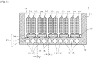
- FIG. 1 shows vertical cross-sectional views of a heat dissipating structure according to a first embodiment and a battery including a plurality of the heat dissipating structures.
- a heat dissipating structure 25 of the first embodiment is provided between a battery cell 20, an example of a heat source, and a cooling member (e.g., cooling water) and enables heat dissipation from the battery cell 20 by conducting heat from the battery cell 20 to the cooling member 15.
- the cooling member may be referred to as a cooling agent.
- the heat dissipating structure 25 includes: a thermally conductive sheet 30 containing at least one of metal, carbon, and ceramic and settable between the battery cell 20 and the cooling member 15; and a cushion member 31 at least partially covered with the thermally conductive sheet 30.
- the thermally conductive sheet 30 has a downward-C-shaped vertical section with an opening 32 facing the cooling member 15 in a part arranged between the battery cell 20 and the cooling member 15.
- the cushion member 31 is arranged inside the thermally conductive sheet 30. Also, in the cushion member 31, at least one end of both ends in a longitudinal direction of the heat dissipating structure 25 (direction of the face side and the back side of the drawing sheet of FIG. 1 ) is preferably exposed from the thermally conductive sheet 30.
- a battery 1 of FIG. 1 includes a plurality of the battery cells 20, as a heat source, in the housing 11 to come into contact with the cooling members 15.
- cross section and “vertical cross section” each mean a cross section in a direction of cutting perpendicularly from the upper opening face in an interior 14 to a bottom 12 of the housing 11 of the battery 1.
- the battery 1 is a battery for electric vehicles, for example, and includes the plurality of battery cells 20.
- the battery 1 includes the bottomed housing 11 opening at one side.
- the housing 11 is preferably made of aluminum or aluminum- based alloy.
- the battery cells 20 are arranged in the interior 14 of the housing 11.
- a plurality of electrodes is protruded on each of the battery cells 20 (see FIG. 2 ).
- the battery cells 20 preferably come in close contact with each other due to force imparted to both sides thereof in a direction to be compressed using, for example, a screw (not shown).
- One or more water cooling pipes 13 are provided at the bottom 12 of the housing 11 to let the cooling water, an example of the cooling member 15, to flow therethrough.
- the battery cells 20 are arranged in the housing 11 to sandwich the heat dissipating structures 25 between the bottom 12 and the battery cells 20.
- each heat dissipating structure 25 mounts one or more of the battery cells 20 arranged in the housing 11.
- heat dissipating structures 25 each mount two of the battery cells 20, the number of the mounted battery cells 20 may be one or three or more.
- the heat dissipating structures 25 in the housing 11 are arranged at a distance "t" from one another not to come into contact with each other even when compressed by the battery cells 20 mounted thereon. This is necessary to avoid collision between adjacent heat dissipating structures 25.
- the distance between the adjacent heat dissipating structures 25 ("t" mentioned above, or “T” described later) is preferably 5 mm, more preferably 2 mm, depending on the amount of deformation and the amount of heat conduction of the heat dissipating structures 25.
- the heat of the battery cells 20 is transferred through the heat dissipating structures 25 to the housing 11 and is efficiently removed by water cooling.
- the cooling member 15 is not limited to the cooling water, but is interpreted to include organic solvents, such as liquid nitrogen and ethanol.
- the cooling member 15 is not necessarily a liquid when used for cooling but may be a gas or a solid.
- the thermally conductive sheet 30 preferably contains carbon, and more preferably contains carbon filler and resin.
- carbon herein is broadly interpreted to include substances having any structure made of carbon (element symbol: C) such as graphite, carbon black having lower crystallinity than graphite, expanded graphite, diamond, diamond like carbon having a structure similar to diamond.
- the resin may account for more than 50%, or the carbon filler may account for more than 50%, of the total mass of the thermally conductive sheet 30.
- the thermally conductive sheet 30 may be mainly made of the resin or mainly made of the carbon filler.
- thermoplastic resin can be suitably used, for example.
- resin having a high melting point that does not melt when conducting heat from the battery cells 20, an example of the heat source, is preferred, and polyphenylene sulfide (PPS), polyether ether ketone (PEEK), polyamide imide (PAI), for example, may be preferably exemplified.
- the thermally conductive sheet 30 is not necessarily required to have excellent electrical conductivity and may have only thermal conduction property.
- the thermally conductive sheet 30 may be a sheet containing AlN, diamond, diamond-like carbon (lower electrical conductivity than graphite).
- its thickness is not restricted but is preferably 0.3 to 5 mm, and more preferably 0.3 to 1 mm. Note that, since the thermal conductivity of the thermally conductive sheet 30 decreases as its thickness increases, the thickness is preferably determined by comprehensively taking the strength, flexibility and thermal conduction property of the sheet into consideration.
- the thermally conductive sheet 30 as a skin includes the cushion member 31 in its internal space. Part of the thermally conductive sheet 30 may be provided with an opening 32 to expose the cushion member 31.
- the cushion member 31 may be either a sponge-like member containing air bubbles, or a rubber-like elastic body containing no air bubbles but is preferably the sponge-like member.
- the cushion member 31 preferably contains: a thermosetting elastomer such as silicone rubber, urethane rubber, isoprene rubber, ethylene propylene rubber, natural rubber, ethylene propylene diene rubber, nitrile rubber (NBR), or styrene butadiene rubber (SBR); a thermoplastic elastomer on urethane basis, ester basis, styrene basis, olefin basis, butadiene basis, or fluorine basis; or a composite thereof.
- a thermosetting elastomer such as silicone rubber, urethane rubber, isoprene rubber, ethylene propylene rubber, natural rubber, ethylene propylene diene rubber, nitrile rubber (NBR), or styrene butadiene rubber (SBR)
- the cushion member 31 is preferably made of high heat-resistant materials capable of maintaining its shape without melting or decomposing by the heat conducted through the thermally conductive sheet 30.
- the cushion member 31 is preferably made of a material in which a urethane-basis elastomer is impregnated with silicone, or silicone rubber.
- the cushion member 31 may be formed by dispersing a filler typified by, for example, AlN, cBN, hBN, and particles of diamond, into the rubber to improve its thermal conduction property to the extent possible.
- FIG. 2 shows a perspective view of the heat dissipating structure of FIG. 1 with two batteries mounted thereon.
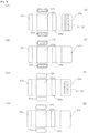
- FIG. 3 shows six views of the modifications (3A, 3B, 3C and 3D) of the heat dissipating structure of FIG. 1 .
- the heat dissipating structure 25 of (3A) in FIG.3 has the structure shown in FIGS. 1 and 2 , in which the thermally conductive sheet 30 covers the substantially rectangular- parallelepiped cushion member 31 except for both end surfaces in the longitudinal direction and a part of a bottom surface of the cushion member 31. Specifically, a top surface 25a and left and right side surfaces 25c, 25d of the heat dissipating structure 25 are covered with the thermally conductive sheet 30. A front surface 25e and a back surface 25f of the heat dissipating structure 25 expose the surfaces of the cushion member 31.
- a heat dissipating structure 25 of (3C) in FIG.3 is a second modification of the heat dissipating structure 25 of (3A) in FIG. 3 and has a structure in which the thermally conductive sheet 30 covers the substantially rectangular parallelepiped cushion member 31 except for a part of the bottom surface of the cushion member 31.
- the heat dissipating structure 25 is not limited to the above-described forms but can be modified.
- a heat dissipating structure 25 having a structure in which the thermally conductive sheet 30 covers the substantially rectangular parallelepiped cushion member 31 except for one end surface of both end surfaces in the longitudinal direction of the cushion member 31 may be used. Owing to the exposure of a part of the cushion member 31 from the thermally conductive sheet 30, the cushion member 31 becomes more susceptible of modifications when the battery cells 20 are mounted on the heat dissipating structure 25.
- FIG. 4 shows vertical cross-sectional views of a heat dissipating structure according to a second embodiment and a battery including a plurality of the heat dissipating structures.
- a battery 1a according to the second embodiment has a structure in which a plurality of heat dissipating structures 25 supports one battery cell 20a larger in size than the battery cell 20 of the first embodiment, which is different from the battery 1 of the first embodiment, and other features are in common with the battery 1.
- a plurality of heat dissipating structures 25 supports one battery cell 20a larger in size than the battery cell 20 of the first embodiment, which is different from the battery 1 of the first embodiment, and other features are in common with the battery 1.
- the housing 11 may have higher electrical conductivity than the thermally conductive sheet 30, provided that the insulation property between the housing 11 and the thermally conductive sheet 30 is ensured.
- the thermally conductive sheet 30 preferably contains carbon filler and resin.
- the carbon filler preferably has electrical conductivity, and is, for example, graphite filler.
- the thermally conductive sheet 30 may be formed of a material excellent in both electrical conductivity and heat conduction property.
Landscapes
- Chemical & Material Sciences (AREA)
- Chemical Kinetics & Catalysis (AREA)
- Electrochemistry (AREA)
- General Chemical & Material Sciences (AREA)
- Engineering & Computer Science (AREA)
- Manufacturing & Machinery (AREA)
- Secondary Cells (AREA)
- Battery Mounting, Suspending (AREA)
- Cooling Or The Like Of Semiconductors Or Solid State Devices (AREA)
Description
- The present application claims the benefit of priorities of Japanese Patent Application No.
2017-248657, filed on December 26, 2017 N2020306, filed on 23 January 2018 - The present invention relates to an arrangement of a heat dissipating structure, a heat source and a cooling member and a battery provided with the same.
- Control systems for vehicles, aircraft, ships, or household or business electronic devices have become more precise and complicated, and accordingly integration densities of compact electronic components on a circuit board have been increasing steadily. Consequently, it is desired to solve problems such as breakdown and shortening of service life of the electronic component due to heat generated in the circuit-board peripheral area
- To rapidly dissipate heat from the circuit board, the circuit board itself has been made of a material having excellent heat dissipation property, a heat sink has been provided, and/or a heat dissipation fan has been operated. Among these measures, making the circuit board of a material excellent in heat dissipation property, such as diamond, aluminum nitride (AlN), or cubic-boron nitride (cBN), extremely increases the cost of the circuit board. Also, installation of the heat dissipation fan leads to problems such as failure of a rotary component, i.e., a fan, the need for maintenance to prevent failures, and difficulty in securing its installation space. On the other hand, heat dissipation fins are widely used as heat dissipation components owing to its simple structure including many columnar or tabular protrusions of a metal having high thermal conduction property (for example, aluminum) to extend its surface areas, thereby to further enhance the heat dissipation (see Patent Literature 1).
- Incidentally, a movement to gradually convert conventional gasoline or diesel vehicles into electric vehicles is now growing around the world to reduce the human impact on the environment. Particularly, in addition to European countries including France, the Netherlands, and Germany, China has declared to switch from gasoline and diesel vehicles to electric vehicles completely by 2040. The development of high- performance battery and installation of many charging stands are needed for spread of electric vehicles. Particularly, the major problem is the development of technology for enhancing the charge and discharge function of lithium-based vehicle battery. It is well known that the vehicle battery cannot sufficiently exhibit the function of charging and discharging at a temperature equals to or higher than 60 degrees Celsius. It is therefore considered important to enhance the heat dissipation of the battery, as well as the circuit board described above.
- To rapidly dissipate the heat of the battery, the battery employs a structure including:
a water cooling pipe arranged in a housing made of a metal having excellent thermal conduction property, such as aluminum; a plurality of battery cells arranged in the housing; and an adhesive rubber sheet sandwiched between the battery cells and the bottom surface of the housing. - Hereinafter, the description will be made with reference to a drawing.
-
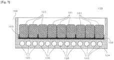
FIG. 7 shows a schematic sectional view of a conventional battery. Abattery 100 ofFIG. 7 includes a plurality ofbattery cells 101 on aninner bottom surface 103 of a housing 102 made of aluminum or aluminum-based alloy.Water cooling pipes 105 for cooling-water flow are provided at abottom 104 of the housing 102. A rubber sheet (for example, a sheet made of silicone rubber curable at room temperature) 106 is interposed between thebattery cells 101 and thebottom 104 to fix thebattery cells 101 in the housing 102. In thebattery 100 having such a structure, heat of thebattery cells 101 is transferred through therubber sheet 106 to the housing 102 and is efficiently removed by water cooling. -
Patent document EP 2 081 421 A2 relates to a heat radiating structure formed at the bottom of the electronic module to release the generated heat from the electronic module, and includes an impact absorber, which absorbs impact transferred from the outside. A heat radiating sheet is formed with a plurality of the multi-layered heat conductive sheets and is in contact with the bottom of the electronic module by covering the outside of the impact absorber. - Patent document
JP 2018 010974 A - [PATENT LITERATURE 1] Japanese Patent Laid-Open No.
2008-243999 - However, the heat dissipating structure of the
conventional battery 100 as shown inFIG. 7 has following problems to be solved. The low thermal conduction property of therubber sheet 106 compared to aluminum or graphite hinders the efficient heat transfer from thebattery cells 101 to the housing 102. Instead of therubber sheet 106, a spacer made of, for example, graphite may be used. However, a gap is generated between thebattery cells 101 and the spacer due to unevenness of lower surfaces of thebattery cells 101, thereby decreasing heat transfer efficiency. Since lower surfaces of battery cells can take various shapes, high- efficiency heat transfer irrespective of the shapes of battery cells is demanded. Also, battery-cell containers made of lighter weight materials, and a heat dissipating structure corresponding to the lightweight battery cell are demanded. This applies not only to batteries but also to other heat sources such as circuit boards and electronic device bodies. - The present invention has been made in view of the above problems, and its object is to provide a heat dissipating structure having excellent heat dissipation efficiency irrespective of shapes and materials of its heat source, and a battery including the same.
-
- (1) A heat dissipating structure in an arrangement according to an embodiment to achieve the above object is provided between a heat source and a cooling member and enables heat dissipation from the heat source by conducting the heat from the heat source to the cooling member. The heat dissipating structure includes: a thermally conductive sheet containing at least one of metal, carbon, and ceramic and settable between the heat source and the cooling member; and a cushion member at least partially covered with the thermally conductive sheet, wherein
the thermally conductive sheet has a downward-C-shaped cross-section with an opening facing the cooling member in a part disposed between the heat source and the cooling member, and a cushion member is arranged inside the thermally conductive sheet. - (2) In a heat dissipating structure according to another embodiment, in any of the cushion members, at least one end of both ends in a longitudinal direction of the heat dissipating structure is preferably exposed from a thermally conductive sheet.
- (3) A heat dissipating structure according to another embodiment preferably further includes a rubber sheet tightly fixing any of the thermally conductive sheets to at least one of the heat source and a periphery of the cooling member.
- (4) In a heat dissipating structure according to another embodiment, the rubber sheet is preferably made of silicone rubber.
- (5) In a heat dissipating structure according to another embodiment, any of the thermally conductive sheets preferably contains carbon filler and resin.
- (6) A heat dissipating structure according to another embodiment preferably further includes energization electrodes capable of supplying electricity to heat any of the thermally conductive sheets or any of the cushion members.
- (7) A battery according to an embodiment includes: a plurality of battery cells, as a heat source, in a housing to come into contact with a cooling member; and any of the heat dissipating structures. The heat dissipating structure includes a thermally conductive sheet containing at least one of metal, carbon, and ceramic and settable between the plurality of battery cells and the cooling member, and a cushion member at least partially covered with the thermally conductive sheet.
- (8) In a battery according to another embodiment, a plurality of the heat dissipating structures is provided in a housing, each heat dissipating structure mounting one or more of battery cells provided in the housing.
- (9) In a battery according to another embodiment, the plurality of heat dissipating structures is arranged at a distance from one another not to come into contact with each other even when compressed by the battery cells mounted on the heat dissipating structures.
- According to the present invention, it is possible to provide a heat dissipating structure having excellent heat dissipation efficiency irrespective of shapes and materials of its heat source and a battery including the same.
-
- [
fig.1] Fig. 1 shows vertical cross-sectional views of a heat dissipating structure according to a first embodiment and a battery including a plurality of the heat dissipating structures; - [
fig.2] Fig. 2 shows a perspective view of the heat dissipating structures ofFIG. 1 with two battery cells mounted thereon; - [
fig.3] Fig. 3 shows six views of the modifications (3A, 3B, 3C and 3D) of the heat dissipating structure ofFIG. 1 ; - [
fig.4] Fig. 4 shows vertical cross-sectional views of a heat dissipating structure according to a second embodiment and a battery including a plurality of the heat dissipating structures; - [
fig.5] Fig. 5 shows vertical cross-sectional views (5A) of a heat dissipating structure according to a third embodiment not being part of the invention and a battery including a plurality of the heat dissipating structures, and six views (5B) of the heat dissipating structure; - [
fig.6] Fig. 6 shows six views (6A, 6B and 6C) of various modifications of the heat dissipating structure according to the present invention; and - [
fig.7] Fig. 7 shows a schematic sectional view of a conventional battery. - 1,1a,1b battery, 11 housing, 12 bottom (an example of cooling member or an example of a part of housing near cooling member), 15 cooling member, 20, 20a battery cell (an example of heat source), 25, 45 heat dissipating structure, 30 thermally conductive sheet, 31 cushion member, 32 opening, 50 rubber sheet, 51, 52 electrodes for energization
- Next, embodiments of the present invention will be described with reference to the drawings. Note that, each of the embodiments described below does not limit the claimed invention and not all the elements and combinations thereof described in the respective embodiments are necessarily essential to the solution of the present invention.
-
FIG. 1 shows vertical cross-sectional views of a heat dissipating structure according to a first embodiment and a battery including a plurality of the heat dissipating structures. - A
heat dissipating structure 25 of the first embodiment is provided between abattery cell 20, an example of a heat source, and a cooling member (e.g., cooling water) and enables heat dissipation from thebattery cell 20 by conducting heat from thebattery cell 20 to the coolingmember 15. The cooling member may be referred to as a cooling agent. Theheat dissipating structure 25 includes: a thermallyconductive sheet 30 containing at least one of metal, carbon, and ceramic and settable between thebattery cell 20 and the coolingmember 15; and acushion member 31 at least partially covered with the thermallyconductive sheet 30. - The thermally
conductive sheet 30 has a downward-C-shaped vertical section with anopening 32 facing the coolingmember 15 in a part arranged between thebattery cell 20 and the coolingmember 15. Thecushion member 31 is arranged inside the thermallyconductive sheet 30. Also, in thecushion member 31, at least one end of both ends in a longitudinal direction of the heat dissipating structure 25 (direction of the face side and the back side of the drawing sheet ofFIG. 1 ) is preferably exposed from the thermallyconductive sheet 30. Abattery 1 ofFIG. 1 includes a plurality of thebattery cells 20, as a heat source, in thehousing 11 to come into contact with the coolingmembers 15. Herein, terms "cross section" and "vertical cross section" each mean a cross section in a direction of cutting perpendicularly from the upper opening face in an interior 14 to a bottom 12 of thehousing 11 of thebattery 1. - In this embodiment, the
battery 1 is a battery for electric vehicles, for example, and includes the plurality ofbattery cells 20. Thebattery 1 includes the bottomedhousing 11 opening at one side. Thehousing 11 is preferably made of aluminum or aluminum- based alloy. Thebattery cells 20 are arranged in the interior 14 of thehousing 11. A plurality of electrodes is protruded on each of the battery cells 20 (seeFIG. 2 ). Thebattery cells 20 preferably come in close contact with each other due to force imparted to both sides thereof in a direction to be compressed using, for example, a screw (not shown). One or morewater cooling pipes 13 are provided at the bottom 12 of thehousing 11 to let the cooling water, an example of the coolingmember 15, to flow therethrough. Thebattery cells 20 are arranged in thehousing 11 to sandwich theheat dissipating structures 25 between the bottom 12 and thebattery cells 20. - Preferably, a plurality of the
heat dissipating structures 25 is provided in thehousing 11 and eachheat dissipating structure 25 mounts one or more of thebattery cells 20 arranged in thehousing 11. Although, in theFIG. 1 ,heat dissipating structures 25 each mount two of thebattery cells 20, the number of the mountedbattery cells 20 may be one or three or more. - The
heat dissipating structures 25 in thehousing 11 are arranged at a distance "t" from one another not to come into contact with each other even when compressed by thebattery cells 20 mounted thereon. This is necessary to avoid collision between adjacentheat dissipating structures 25. The distance between the adjacent heat dissipating structures 25 ("t" mentioned above, or "T" described later) is preferably 5 mm, more preferably 2 mm, depending on the amount of deformation and the amount of heat conduction of theheat dissipating structures 25. - In the
battery 1 having such a structure, the heat of thebattery cells 20 is transferred through theheat dissipating structures 25 to thehousing 11 and is efficiently removed by water cooling. The coolingmember 15 is not limited to the cooling water, but is interpreted to include organic solvents, such as liquid nitrogen and ethanol. The coolingmember 15 is not necessarily a liquid when used for cooling but may be a gas or a solid. - In this embodiment, the thermally
conductive sheet 30 between thebattery cells 20 and the bottom 12 has a downward-C shape in a vertical cross-sectional view. The downward-C shape may be referred to as a downward-U shape.FIG. 1 illustrates the thermallyconductive sheet 30 having the downward-C shape. However, since thermal conductivity is enhanced when an outer surface of the thermallyconductive sheet 30, but not its end faces, is in contact with the bottom 12, the thermallyconductive sheet 30 has the downward-C shape in the vertical cross-sectional view. - The thermally
conductive sheet 30 preferably contains carbon, and more preferably contains carbon filler and resin. The term "carbon" herein is broadly interpreted to include substances having any structure made of carbon (element symbol: C) such as graphite, carbon black having lower crystallinity than graphite, expanded graphite, diamond, diamond like carbon having a structure similar to diamond. - In this embodiment, the thermally
conductive sheet 30 may be a thin sheet formed by curing a material in which graphite fibers and carbon particles are mixed and dispersed in resin. Instead of the graphite fibers or the carbon particles, an expanded graphite filler may be used. Expanded graphite is a graphite in which a graphite intercalation compound formed by inserting a substance into flake graphite by a chemical reaction is rapidly heated to gasify the substance between the layers, and the release of the gas generated at that time causes expansion of the interlayer spacing of the graphite, thus expanding in the stacking direction. The graphite fibers, the carbon particles, or the expanded graphite filler are all included in the concept of the carbon filler. - The thermally
conductive sheet 30 may contain at least one of metal and ceramic instead of or in addition to carbon. The metal can be selected from materials having relatively high thermal conductivity such as aluminum, copper, and an alloy containing at least one of them. The ceramic can be selected from materials having relatively high thermal conductivity, such as AlN, cBN, and hBN. - The resin may account for more than 50%, or the carbon filler may account for more than 50%, of the total mass of the thermally
conductive sheet 30. As long as there is no serious problem in the thermal conduction, the thermallyconductive sheet 30 may be mainly made of the resin or mainly made of the carbon filler. For the resin, thermoplastic resin can be suitably used, for example. For the thermoplastic resin, resin having a high melting point that does not melt when conducting heat from thebattery cells 20, an example of the heat source, is preferred, and polyphenylene sulfide (PPS), polyether ether ketone (PEEK), polyamide imide (PAI), for example, may be preferably exemplified. The resin is dispersed in the form of, for example, particles in the empty space in the carbon filler before molding of the thermallyconductive sheet 30. In the thermallyconductive sheet 30, in addition to the carbon filler and the resin, AIN or diamond may be dispersed as a filler for further improving the thermal conduction. An elastomer more flexible than the resin may be used instead of the resin. - The thermally
conductive sheet 30 preferably has excellent thermal conduction property compared to thecushion member 31 described later but is not necessarily required to have excellent electrical conductivity. The thermal conductivity of the thermallyconductive sheet 30 preferably equals to or higher than 10 W/m K. In this embodiment, the thermallyconductive sheet 30 preferably contains the graphite and the carbon having lower crystallinity than the graphite to configure a network facilitating electrical flow in the thermallyconductive sheet 30. - However, the thermally
conductive sheet 30 is not necessarily required to have excellent electrical conductivity and may have only thermal conduction property. In that case, the thermallyconductive sheet 30 may be a sheet containing AlN, diamond, diamond-like carbon (lower electrical conductivity than graphite). As long as the thermallyconductive sheet 30 has a curved nature (or bendability), its thickness is not restricted but is preferably 0.3 to 5 mm, and more preferably 0.3 to 1 mm. Note that, since the thermal conductivity of the thermallyconductive sheet 30 decreases as its thickness increases, the thickness is preferably determined by comprehensively taking the strength, flexibility and thermal conduction property of the sheet into consideration. - In the
heat dissipating structure 25, the thermallyconductive sheet 30 as a skin includes thecushion member 31 in its internal space. Part of the thermallyconductive sheet 30 may be provided with anopening 32 to expose thecushion member 31. - The
cushion member 31 is an elastic body covered with the thermallyconductive sheet 30. Thecushion member 31 is provided between thebattery cells 20 and the bottom 12 to have a function of exhibiting cushioning property and a function as a protective member preventing theconductive sheet 30 from, for example, being damaged due to the load applied to the thermallyconductive sheet 30. Thecushion member 31 has low thermal conduction property compared to the thermallyconductive sheet 30. - The
cushion member 31 may be either a sponge-like member containing air bubbles, or a rubber-like elastic body containing no air bubbles but is preferably the sponge-like member. Thecushion member 31 preferably contains: a thermosetting elastomer such as silicone rubber, urethane rubber, isoprene rubber, ethylene propylene rubber, natural rubber, ethylene propylene diene rubber, nitrile rubber (NBR), or styrene butadiene rubber (SBR); a thermoplastic elastomer on urethane basis, ester basis, styrene basis, olefin basis, butadiene basis, or fluorine basis; or a composite thereof. Thecushion member 31 is preferably made of high heat-resistant materials capable of maintaining its shape without melting or decomposing by the heat conducted through the thermallyconductive sheet 30. In his embodiment, thecushion member 31 is preferably made of a material in which a urethane-basis elastomer is impregnated with silicone, or silicone rubber. Thecushion member 31 may be formed by dispersing a filler typified by, for example, AlN, cBN, hBN, and particles of diamond, into the rubber to improve its thermal conduction property to the extent possible. -
FIG. 2 shows a perspective view of the heat dissipating structure ofFIG. 1 with two batteries mounted thereon. - The
battery cells 20 each includeelectrodes FIGS 1 ,2 ). The heat produced by thebattery cells 20 in charging or discharging is transferred from lower ends of thebattery cells 20 through the thermallyconductive sheet 30 of the heat dissipating structure 25 (see arrows F inFIG. 2 ) to the bottom 12 of thehousing 11, and then to the coolingmember 15. In this way, effective heat removal of thebattery cells 20 is achieved. -
FIG. 3 shows six views of the modifications (3A, 3B, 3C and 3D) of the heat dissipating structure ofFIG. 1 . - The
heat dissipating structure 25 of (3A) inFIG.3 has the structure shown inFIGS. 1 and2 , in which the thermallyconductive sheet 30 covers the substantially rectangular-parallelepiped cushion member 31 except for both end surfaces in the longitudinal direction and a part of a bottom surface of thecushion member 31. Specifically, atop surface 25a and left and right side surfaces 25c, 25d of theheat dissipating structure 25 are covered with the thermallyconductive sheet 30. Afront surface 25e and aback surface 25f of theheat dissipating structure 25 expose the surfaces of thecushion member 31. Abottom face 25b of theheat dissipating structure 25 is covered with the thermallyconductive sheet 30 to form theopening 32 in a central region in the width direction of theheat dissipating structure 25. Thecushion member 31 is exposed from theopening 32. Although in this embodiment, thecushion member 31 does not protrude to the outside of the thermallyconductive sheet 30, the bottom surface of thecushion member 31 may protrude towards the outside up to a position flush with the thermallyconductive sheet 30 or further outward than the thermallyconductive sheet 30. - A
heat dissipating structure 25 of (3B) inFIG.3 is a first modification of theheat dissipating structure 25 of (3A) inFIG. 3 and has a structure in which the thermallyconductive sheet 30 covers the substantially rectangularparallelepiped cushion member 31 except for both end surfaces in the longitudinal direction of thecushion member 31. Specifically, a top surface 25g, abottom surface 25h, and left and right both side surfaces 25i, 25j are covered with the thermallyconductive sheet 30. Afront surface 25k and aback surface 251 of theheat dissipating structure 25 expose the surfaces of thecushion member 31. - A
heat dissipating structure 25 of (3C) inFIG.3 is a second modification of theheat dissipating structure 25 of (3A) inFIG. 3 and has a structure in which the thermallyconductive sheet 30 covers the substantially rectangularparallelepiped cushion member 31 except for a part of the bottom surface of thecushion member 31. - Specifically, a
top surface 25m, left and right side surfaces 25o, 25p,front surface 25q, and a back surface 25r are covered with the thermallyconductive sheet 30. A part of a bottom surface 25n of theheat dissipating structure 25 has theopening 32 to expose the surface of thecushion member 31. The bottom surface 25n of theheat dissipating structure 25 has theopening 32 in its substantially central part. Although in this embodiment, thecushion member 31 does not protrude to the outside of the thermallyconductive sheet 30, the bottom surface of thecushion member 31 may protrude towards the outside up to a position flush with the thermallyconductive sheet 30 or further outward than the thermallyconductive sheet 30. - A
heat dissipating structure 25 of (3D) inFIG. 3 is a third modification of theheat dissipating structure 25 of (3A) inFIG. 3 and has a structure in which the thermallyconductive sheet 30 covers all surfaces of the substantially rectangularparallelepiped cushion member 31. Specifically, a top surface 25s, aback surface 25t, left andright side surfaces 25u, 25v, front surface 25w, and aback surface 25x are covered with the thermallyconductive sheet 30. - The
heat dissipating structure 25 is not limited to the above-described forms but can be modified. For example, aheat dissipating structure 25 having a structure in which the thermallyconductive sheet 30 covers the substantially rectangularparallelepiped cushion member 31 except for one end surface of both end surfaces in the longitudinal direction of thecushion member 31 may be used. Owing to the exposure of a part of thecushion member 31 from the thermallyconductive sheet 30, thecushion member 31 becomes more susceptible of modifications when thebattery cells 20 are mounted on theheat dissipating structure 25. - Next, a method of assembling (= manufacturing method) the
battery 1 according to this embodiment will be exemplified. - (a) A resin material typified by PPS, etc., and at least one of graphite filler and carbon filler having lower crystallinity than graphite (preferred in the form of particles, fibers, etc.) are stirred in a liquid (water, for example) to form a felt sheet in the same method as papermaking.
- (b) Subsequently, the felt sheet is shaped to have a cross sectional shape identical or similar to that of the thermally
conductive sheet 30 ofFIG. 1 . - (c) The
cushion member 31 is put inside the thermallyconductive sheet 30 to complete theheat dissipating structure 25. At this time, thecushion member 31 and the thermallyconductive sheet 30 may be fixed using or without using fixing means such as a heat resistant adhesive, a double-sided tape, or a screw. - (d) Lastly, the
heat dissipating structure 25 is assembled into thebattery 1. The heat dissipating structure can be mounted on the bottom 12 with or without a heat resistant adhesive or double-sided tapes applied therebetween. The manufacturing method can be adopted in a second embodiment and in subsequent embodiments. - Subsequently, a second embodiment of the heat dissipating structure according to the present invention and the battery including the same will be described. In the second embodiment, the common features with the first embodiment are described in the description of the first embodiment and redundant description is omitted.
-
FIG. 4 shows vertical cross-sectional views of a heat dissipating structure according to a second embodiment and a battery including a plurality of the heat dissipating structures. - A battery 1a according to the second embodiment has a structure in which a plurality of
heat dissipating structures 25 supports onebattery cell 20a larger in size than thebattery cell 20 of the first embodiment, which is different from thebattery 1 of the first embodiment, and other features are in common with thebattery 1. Hereinafter, the features different from the first embodiment will be described. - In the battery 1a according to the second embodiment, the
battery cell 20a is mounted on fiveheat dissipating structures 25 having the same structure as in the first embodiment. Theheat dissipating structures 25 are compressed by the weight of the battery cell la. This brings each thermallyconductive sheet 30 into close contact with both thebattery cell 20a and the bottom 12 of thehousing 11, thereby improving the thermal conduction property. Note that, each of theheat dissipating structures 25 in thehousing 11 is arranged at the distance "t" from one another not to come into contact with each other even when compressed by mounting thereon thebattery cell 20a. - Subsequently, a third embodiment of the heat dissipating structure according to the present invention and the battery including the same will be described. In the third embodiment, features in common with each of the above-described embodiments are described in the description of the respective embodiments and redundant description is omitted.
-
FIG. 5 shows vertical cross-sectional views (5A) of a heat dissipating structure according to a third embodiment not being part of the invention and a battery including a plurality of the heat dissipating structures, and six views (5B) of the heat dissipating structure. - In a battery 1b according to the third embodiment, a
heat dissipating structures 45 having a substantially parallelogram shape in the vertical sectional view supports thebattery cells 20, which is different from thebattery 1 according to the first embodiment, and other features are in common with thebatteries 1. Hereinafter, the features different from the first embodiment will be mainly described. - As shown in
FIG. 5 , in theheat dissipating structure 45, all surfaces of thecolumnar cushion member 31 having substantially parallelogram-shaped end surfaces are fully covered with the thermallyconductive sheet 30. The (5A) inFIG. 5 illustrates a vertical cross section of theheat dissipating structure 45. The number ofheat dissipating structures 45 arranged in thehousing 11 is four. Each of theheat dissipating structures 45 mounts two of thebattery cells 20. Theheat dissipating structures 45 lean toward the bottom 12 by the weight of thebattery cells 20 and are compressed. Since each thermallyconductive sheet 30 is in surface contact with the bottom 12 of thehousing 11, heat is easily transferred from thebattery cells 20 to the bottom 12. Theheat dissipating structures 45 are arranged at a distance "T" from one another not to abut with each other even when compressed to lean toward the bottom 12. Though two of thebattery cells 20 are arranged on eachheat dissipating structure 45, the number of the mountedbattery cells 20 may be one or three or more. - In the
heat dissipating structure 45, all six surfaces, i.e., atop surface 45a a bottom surface 45b, left and right side surfaces 45c, 45d, front surface 45e, and a back surface 45f of thecushion member 31 are covered with the thermallyconductive sheet 30. Thecushion member 31 is not exposed to the outside of theheat dissipating structure 45. However, like the variousheat dissipating structures 25 described in the first embodiment (seeFIG. 3 ), theheat dissipating structure 45 may have thecushion member 31 exposed to the outside. -
FIG. 6 shows six views (6A, 6B and 6C) of various modifications of the heat dissipating structure according to the present invention. - The following various modifications can be included to at least one of the
batteries 1, 1a, 1b. - A
heat dissipating structure 25 of (6A) inFIG. 6 is a first modification in which an energization heating mechanism is added to theheat dissipating structure 25 of (3A) inFIG. 3 . Theheat dissipating structure 25 of the first modification includes electrodes for energization (also simply referred to as "electrodes" or "electrode") 51, 52 capable of supplying electricity to heat the thermallyconductive sheet 30 or thecushion member 31. Theelectrodes top surface 25a so that the current flows in a direction from theelectrode 51 to the electrode 52 (direction of a black thick arrow). In this modification, theelectrodes electrodes conductive sheet 30 and the rubber sheet 50. The rubber sheet 50 has a function of tightly fixing the thermallyconductive sheet 30 to the periphery of thebattery cells 20. The rubber sheet 50 is electrically conductive and formed of a resistive heating material. For this reason, the rubber sheet 50 functions as a sheet, letting the current flow from theelectrode 51 to theelectrode 52, thereby generating heat resulting from its electrical resistance. The rubber sheet 50 is required to have excellent electrical conductivity compared to the thermallyconductive sheet 30. This is to let the current flow preferentially to the rubber sheet 50 with respect to the thermallyconductive sheet 30 when a voltage is applied between theelectrodes - The rubber sheet 50 can be formed of various kinds of elastic bodies like the above-described
cushion member 31 but is preferably made mainly of a rubber that can be heated by energization and has excellent thermal conduction property, as it is necessary to rapidly transfer the heat from thebattery cells 20 to the thermallyconductive sheet 30. Preferably, when the rubber sheet 50 is made mainly of silicone rubber, a filler such as graphite or aluminum is dispersed in the silicone rubber. More preferably, in addition to this, a filler such as AlN or alumina is dispersed in the silicone rubber. The rubber sheet 50 made of silicone rubber may be exemplified by a silicone rubber combining bifunctional silicone raw rubber with silicone resin to increase its stickiness. The silicone resin is preferably exemplified by MQ resin. The MQ resin is formed by crosslinking each Q unit with four-dimensional branching in which an oxygen atom is bonded to each four bonds of a Si atom and then, to stop the reactivity of the end group, bonding thereto M units with one-dimensional branching in which an oxygen atom is bonded to a bond of each Si atom. The silicone resin containing lots of hydroxyl groups is preferably used to enhance its stickiness. - The rubber sheet 50 preferably has a function of enhancing adhesiveness between the
battery cells 20 and the thermallyconductive sheet 30. As long as the rubber sheet 50 has electrical conductivity, heat resistant property, and stickiness, its hardness is not limited, but in the case of a sheet made mainly of silicone rubber, the sheet has a Shore OO hardness of 60, preferably 40 or less, and more preferably 10 or less. This is because the lower the hardness of the rubber sheet 50, the easier it is to absorb un- evenness on surfaces of thebattery cells 20. Further, the rubber sheet 50 preferably has a thickness of 0.3-5 mm, more preferably 0.7-3 mm, and even more preferably 1-2.5 mm. Note that, the thickness of the rubber sheet 50 is preferably determined in accordance with conditions such as thicknesses of theelectrodes battery cells 20, and the hardness of the rubber. - A
heat dissipating structure 25 of (6B) inFIG. 6 is a second modification differentiated from the first modification in the mounting position and shape of theelectrodes conductive sheet 30 generates heat using its electrical conductivity (it may be referred also as electrical resistance) by the electrical supply from theelectrode 51 to theelectrode 52. Theelectrodes electrode 51 to the electrode 52 (direction of thick black arrows). In this case, the thermallyconductive sheet 30 has higher electrical conductivity than thehousing 11 because it is not preferable that the current flow to thehousing 11. However, thehousing 11 may have higher electrical conductivity than the thermallyconductive sheet 30, provided that the insulation property between thehousing 11 and the thermallyconductive sheet 30 is ensured. The thermallyconductive sheet 30 preferably contains carbon filler and resin. The carbon filler preferably has electrical conductivity, and is, for example, graphite filler. The thermallyconductive sheet 30 may be formed of a material excellent in both electrical conductivity and heat conduction property. - A
heat dissipating structure 25 of (6C) inFIG. 6 is a third modification differentiated from the second modification in mounting positions of theelectrodes electrodes top surface 25a by rotating the respective electrodes of the first modification by 90 degrees so that the current flows in a direction from theelectrode 51 to the electrode 52 (direction of a thick black arrow). The thermallyconductive sheet 30 generates heat utilizing own electrical conductivity by the supply of electricity to theelectrode 52 from theelectrode 51, which is in common with the second modification. - A rubber sheet having a low hardness similar to the rubber sheet 50 may be interposed between the thermally
conductive sheet 30 and the bottom 12. In this case, the rubber sheet has a function of tightly fixing the thermallyconductive sheet 30 to a periphery of the cooling member 15 (the bottom 12, i.e.). It is sufficient if the rubber sheet has a function of facilitating the transfer of heat received from thebattery cells 20 through the thermallyconductive sheet 30 to the bottom 12, and high electric conductivity is not required for the rubber sheet. The rubber sheet is not an essential component to theheat dissipating structure 25 and thebatteries 1, 1a, 1b. - Preferred embodiments of the present invention have been described as above, but the present invention is not limited to these embodiments, and various modifications can be made.
- For example, the heat source includes not only the
battery cells member 15 may be not only water for cooling but also organic solvent, liquid nitrogen, or gas for cooling. Further, theheat dissipating structures batteries 1, 1a, 1b, but also in, for example, electronic devices, household electric appliances, and power generation devices. - A part of each
heat dissipating structure 25, 45 (the thermallyconductive sheet 30 alone or the thermallyconductive sheet 30 and the cushion member 31) may be inserted into a gap between thebattery cells 20. - Additionally, any components of each of the embodiments may be freely combined except when it is impossible to combine the components with each other. For example, in the third embodiment, one
battery cell 20a as in the second embodiment may be supported by a plurality of theheat dissipating structures 45. Each of the various modifications of theheat dissipating structure 25 shown inFIG. 6 can be used instead of theheat dissipating structures - The heat dissipating structures according to the present invention can also be used for various electronic devices such as vehicles, industrial robots, power generation devices, PCs, and household electric appliances, in addition to vehicle batteries, for example. The batteries according to the present invention can also be used as home-use chargeable and dischargeable batteries and batteries for electronic devices such as PCs, in addition to the vehicle batteries.
Claims (9)
- An arrangement of a heat dissipating structure (25), a heat source (20) and a cooling member (15), the heat dissipating structure (25) being provided between the heat source (20) and the cooling member (15) and enabling heat dissipation from the heat source (20) by conducting heat from the heat source (20) to the cooling member (15), said heat dissipating structure comprising:a thermally conductive sheet (30) comprising at least one of metal, carbon, and ceramic and settable between the heat source (20) and the cooling member (15); anda cushion member (31) at least partially covered with the thermally conductive sheet (30),wherein the thermally conductive sheet (30) has a downward-C-shaped cross section with an opening (32) facing the cooling member (15) in a part disposed between the heat source (20) and the cooling member (15), andthe cushion member (31) is arranged inside the thermally conductive sheet (30).
- The arrangement of claim 1,
wherein in the cushion member (31), at least one end of both ends in a longitudinal direction of the heat dissipating structure (25) is exposed from the thermally conductive sheet (30). - The arrangement of claim 1 or 2, further comprising a rubber sheet (50) tightly fixing the thermally conductive sheet (30) to at least one of the heat source (20) and a periphery of the cooling member (15).
- The arrangement of claim 3,
wherein the rubber sheet (50) is made of silicone rubber. - The arrangement of any one of claims 1 to 4,
wherein the thermally conductive sheet (30) comprises carbon filler and resin. - The arrangement of any one of claims 1 to 5, further comprising energization electrodes (21, 22) capable of supplying electricity to heat the thermally conductive sheet (30) or the cushion member (31).
- A battery (1) comprising an arrangement according to claims 1-6, said arrangement comprising:a plurality of battery cells (20), as a heat source, in a housing (11) to come into contact with a cooling member (15); anda dissipating structure (25), comprising:a thermally conductive sheet (30) comprising at least one of metal, carbon, and ceramic and settable between the plurality of battery cells (20) and the cooling member (15); anda cushion member (31) at least partially covered with the thermally conductive sheet (30), wherein the thermally conductive sheet (30) has a downward-C-shaped cross section with an opening(32) facing the cooling member (15) in a part disposed between the heat source (20) and the cooling member (15), and the cushion member (31) is arranged inside the thermally conductive sheet (30).
- The battery (1) of claim 7, wherein a plurality of the heat dissipating structures (25) is provided in the housing (11), each heat dissipating structure (25) mounting one or more of the battery cells (20) in the housing (11).
- The battery (1) of claim 8, wherein the plurality of heat dissipating structures (25) is arranged at a distance from one another not to come into contact with each other even when compressed by the battery cells (20) mounted on the heat dissipating structures (25).
Applications Claiming Priority (3)
| Application Number | Priority Date | Filing Date | Title |
|---|---|---|---|
| JP2017248657 | 2017-12-26 | ||
| NL2020306A NL2020306B1 (en) | 2018-01-23 | 2018-01-23 | Heat dissipating structure and battery provoded with the same |
| PCT/JP2018/044662 WO2019131018A1 (en) | 2017-12-26 | 2018-12-05 | Heat dissipating structure and battery provided with the same |
Publications (2)
| Publication Number | Publication Date |
|---|---|
| EP3529851A1 EP3529851A1 (en) | 2019-08-28 |
| EP3529851B1 true EP3529851B1 (en) | 2021-04-07 |
Family
ID=64665818
Family Applications (1)
| Application Number | Title | Priority Date | Filing Date |
|---|---|---|---|
| EP18819560.6A Active EP3529851B1 (en) | 2017-12-26 | 2018-12-05 | Heat dissipating structure and battery provided with the same |
Country Status (5)
| Country | Link |
|---|---|
| US (1) | US11495842B2 (en) |
| EP (1) | EP3529851B1 (en) |
| JP (1) | JP6929464B2 (en) |
| CN (1) | CN111357149B (en) |
| WO (1) | WO2019131018A1 (en) |
Families Citing this family (9)
| Publication number | Priority date | Publication date | Assignee | Title |
|---|---|---|---|---|
| JP2021015696A (en) * | 2019-07-11 | 2021-02-12 | 信越ポリマー株式会社 | Heat dissipation structure and battery having the same |
| KR102788863B1 (en) * | 2019-07-23 | 2025-03-31 | 에스케이온 주식회사 | Battery module |
| JP2023513850A (en) * | 2019-12-11 | 2023-04-03 | ブレン-トロニクス,インコーポレイテッド | Thermal management system for rechargeable batteries |
| CN112531236B (en) * | 2020-12-24 | 2022-05-13 | 大连理工江苏研究院有限公司 | High-efficient heat abstractor that new energy automobile battery was used |
| CN113097604A (en) * | 2021-04-02 | 2021-07-09 | 信骅(上海)器材有限公司 | Special graphene heat dissipation assembly with low thermal resistance, high compressibility and buffering function for electric automobile and preparation method of special graphene heat dissipation assembly |
| JP7556900B2 (en) * | 2022-02-09 | 2024-09-26 | プライムプラネットエナジー&ソリューションズ株式会社 | Battery Module |
| JP2024008590A (en) * | 2022-07-08 | 2024-01-19 | トヨタ自動車株式会社 | battery pack structure |
| CN120035539A (en) * | 2022-10-04 | 2025-05-23 | 软银集团股份有限公司 | Cooling system, cooling execution device, cooling device, cooling execution method, cooling method, program, cooling execution program, and cooling program |
| CN121601922A (en) * | 2024-08-24 | 2026-03-03 | 宁德时代未来能源(上海)研究院有限公司 | Battery, power utilization device, energy storage system and power station |
Citations (2)
| Publication number | Priority date | Publication date | Assignee | Title |
|---|---|---|---|---|
| EP2081421A2 (en) * | 2008-01-17 | 2009-07-22 | Samsung Electronics Co., Ltd. | Heat Radiating Structure for Electronic Module and Electronic Device having the Same |
| JP2018010974A (en) * | 2016-07-14 | 2018-01-18 | 信越ポリマー株式会社 | Heat conduction connector and electronic apparatus including the same |
Family Cites Families (26)
| Publication number | Priority date | Publication date | Assignee | Title |
|---|---|---|---|---|
| US3544375A (en) * | 1967-05-22 | 1970-12-01 | Samuel Ruben | Rechargeable fuel cell |
| US4808494A (en) * | 1986-03-12 | 1989-02-28 | Combustion Engineering, Inc. | Thermally actuated hydrogen secondary battery |
| JPH11354166A (en) * | 1998-06-08 | 1999-12-24 | Sony Tektronix Corp | Battery temperature controller |
| US6953637B2 (en) * | 2001-06-01 | 2005-10-11 | Energy Related Devices, Inc. | Catalytic hydrogen vent filter for batteries |
| US7282294B2 (en) * | 2004-07-02 | 2007-10-16 | General Electric Company | Hydrogen storage-based rechargeable fuel cell system and method |
| JP2006054356A (en) * | 2004-08-13 | 2006-02-23 | Agilent Technol Inc | Thermal conduction member |
| JP2007184392A (en) | 2006-01-06 | 2007-07-19 | Taika:Kk | Thermal conductive structure, heat dissipation member and electronic device using the same |
| JP2008243999A (en) | 2007-03-26 | 2008-10-09 | Sumitomo Electric Ind Ltd | Heat dissipation parts and electronic equipment |
| KR101022857B1 (en) * | 2008-01-16 | 2011-03-17 | 인하대학교 산학협력단 | Manufacturing Method of Transition Metal Plated Porous Carbon Nanofiber Composite for Hydrogen Storage |
| US9196938B2 (en) * | 2010-07-06 | 2015-11-24 | Samsung Sdi Co., Ltd. | Battery module |
| CA3053807A1 (en) * | 2010-10-29 | 2012-05-03 | Dana Canada Corporation | Heat exchanger and battery unit structure for cooling thermally conductive batteries |
| EP2650960B1 (en) * | 2011-01-26 | 2020-01-01 | LG Chem, Ltd. | Cooling element having improved assembly productivity and battery modules including same |
| JP2012190674A (en) | 2011-03-11 | 2012-10-04 | Sanyo Electric Co Ltd | Battery device |
| JP2013012441A (en) * | 2011-06-30 | 2013-01-17 | Sanyo Electric Co Ltd | Electric power source device and vehicle including the same |
| FR2986190B1 (en) * | 2012-02-01 | 2015-02-27 | Plastic Omnium Cie | CASE FOR ELECTRICAL MODULE OF A BATTERY PACK FOR MOTOR VEHICLE AND BATTERY PACK FOR MOTOR VEHICLE |
| DE102013201102A1 (en) * | 2013-01-24 | 2014-08-07 | Robert Bosch Gmbh | Device for controlling the temperature of battery cells |
| DE102013007252B3 (en) * | 2013-04-26 | 2014-08-21 | Audi Ag | Method for producing energy storage device, involves determining supply amount of thermally conductive, pasty material to single base to form a planar coating, in dependence on the respective housing-specific detection result |
| DE102014201220A1 (en) * | 2014-01-23 | 2015-07-23 | Robert Bosch Gmbh | battery module |
| DE102014019002A1 (en) * | 2014-12-18 | 2016-06-23 | Daimler Ag | Motor vehicle battery |
| KR102073950B1 (en) * | 2016-01-06 | 2020-03-02 | 주식회사 엘지화학 | Battery Pack Having Edge Cooling-Typed Member |
| US10644364B2 (en) * | 2016-10-17 | 2020-05-05 | David Fortenbacher | Self-heating cells and self-heating batteries including the self-heating cells |
| CN106374162B (en) * | 2016-11-02 | 2019-04-30 | 上海工程技术大学 | A method and device for thermal management of battery module based on thermoelectric effect |
| KR102322289B1 (en) * | 2017-01-03 | 2021-11-05 | 현대자동차주식회사 | Heat releasing composite, the aluminium pouch film comprising the same, and the water cooling system using the same |
| KR102641151B1 (en) * | 2017-08-11 | 2024-02-28 | 더 보드 오브 트러스티스 오브 더 리랜드 스탠포드 쥬니어 유니버시티 | Metallic hydrogen batteries for large-scale energy storage |
| US10969144B2 (en) * | 2017-08-16 | 2021-04-06 | Art Brisebois | Thin multi-channel heat exchanger |
| US10211494B1 (en) * | 2017-09-15 | 2019-02-19 | Boris Tsenter | Lithium hydrogen secondary electrochemical cell |
-
2018
- 2018-12-05 WO PCT/JP2018/044662 patent/WO2019131018A1/en not_active Ceased
- 2018-12-05 JP JP2020535485A patent/JP6929464B2/en active Active
- 2018-12-05 US US16/769,573 patent/US11495842B2/en active Active
- 2018-12-05 EP EP18819560.6A patent/EP3529851B1/en active Active
- 2018-12-05 CN CN201880073543.2A patent/CN111357149B/en active Active
Patent Citations (2)
| Publication number | Priority date | Publication date | Assignee | Title |
|---|---|---|---|---|
| EP2081421A2 (en) * | 2008-01-17 | 2009-07-22 | Samsung Electronics Co., Ltd. | Heat Radiating Structure for Electronic Module and Electronic Device having the Same |
| JP2018010974A (en) * | 2016-07-14 | 2018-01-18 | 信越ポリマー株式会社 | Heat conduction connector and electronic apparatus including the same |
Also Published As
| Publication number | Publication date |
|---|---|
| JP6929464B2 (en) | 2021-09-01 |
| EP3529851A1 (en) | 2019-08-28 |
| WO2019131018A1 (en) | 2019-07-04 |
| CN111357149B (en) | 2024-06-07 |
| JP2020533776A (en) | 2020-11-19 |
| US11495842B2 (en) | 2022-11-08 |
| US20210376401A1 (en) | 2021-12-02 |
| CN111357149A (en) | 2020-06-30 |
Similar Documents
| Publication | Publication Date | Title |
|---|---|---|
| EP3529851B1 (en) | Heat dissipating structure and battery provided with the same | |
| JP6871183B2 (en) | Heat dissipation structure and battery with it | |
| US10720681B2 (en) | Heat dissipation structure and battery provided with the same | |
| JP7001501B2 (en) | Heat dissipation structure and battery with it | |
| JP7116781B2 (en) | Heat dissipation structure and battery with same | |
| JP7116653B2 (en) | Heat dissipation structure and battery with same | |
| JP7503432B2 (en) | Heat dissipation structure and battery equipped with same | |
| JP7190311B2 (en) | Thermal structure and battery | |
| CN213071222U (en) | Heat-dissipating structure and battery mounted with the heat-dissipating structure | |
| CN115398716B (en) | Heat dissipation structure and battery having the same | |
| CN113302781B (en) | Heat radiation structure and battery with the same | |
| TW202030906A (en) | Heat dissipation structure and battery having the structure | |
| CN213638645U (en) | Heat dissipation structure and battery | |
| NL2020306B1 (en) | Heat dissipating structure and battery provoded with the same | |
| JP7772885B1 (en) | Heat dissipation structure and battery using the same | |
| NL2019888B1 (en) | Heat dissipating structure, and battery provided with the same | |
| JP7174674B2 (en) | Heat dissipation structure, method for manufacturing heat dissipation structure, heat dissipation unit, method for manufacturing heat dissipation unit, and battery | |
| JP2022187504A (en) | Thermal structures, batteries and electronics | |
| NL2020444B1 (en) | Heat dissipating structure and battery provided with the same | |
| JP2019220261A (en) | Heat dissipation structure and battery | |
| WO2022034759A1 (en) | Heat dissipation member, heat dissipation structure, and battery | |
| JP2020009579A (en) | Heat dissipation structure and battery | |
| JP2022147019A (en) | Heat transfer unit and battery with same | |
| JP2020202272A (en) | Heat dissipation structure and battery having the same |
Legal Events
| Date | Code | Title | Description |
|---|---|---|---|
| STAA | Information on the status of an ep patent application or granted ep patent |
Free format text: STATUS: UNKNOWN |
|
| STAA | Information on the status of an ep patent application or granted ep patent |
Free format text: STATUS: THE INTERNATIONAL PUBLICATION HAS BEEN MADE |
|
| PUAI | Public reference made under article 153(3) epc to a published international application that has entered the european phase |
Free format text: ORIGINAL CODE: 0009012 |
|
| STAA | Information on the status of an ep patent application or granted ep patent |
Free format text: STATUS: REQUEST FOR EXAMINATION WAS MADE |
|
| STAA | Information on the status of an ep patent application or granted ep patent |
Free format text: STATUS: EXAMINATION IS IN PROGRESS |
|
| 17P | Request for examination filed |
Effective date: 20190506 |
|
| AK | Designated contracting states |
Kind code of ref document: A1 Designated state(s): AL AT BE BG CH CY CZ DE DK EE ES FI FR GB GR HR HU IE IS IT LI LT LU LV MC MK MT NL NO PL PT RO RS SE SI SK SM TR |
|
| AX | Request for extension of the european patent |
Extension state: BA ME |
|
| 17Q | First examination report despatched |
Effective date: 20190805 |
|
| GRAP | Despatch of communication of intention to grant a patent |
Free format text: ORIGINAL CODE: EPIDOSNIGR1 |
|
| STAA | Information on the status of an ep patent application or granted ep patent |
Free format text: STATUS: GRANT OF PATENT IS INTENDED |
|
| DAV | Request for validation of the european patent (deleted) | ||
| DAX | Request for extension of the european patent (deleted) | ||
| INTG | Intention to grant announced |
Effective date: 20201203 |
|
| GRAS | Grant fee paid |
Free format text: ORIGINAL CODE: EPIDOSNIGR3 |
|
| GRAA | (expected) grant |
Free format text: ORIGINAL CODE: 0009210 |
|
| STAA | Information on the status of an ep patent application or granted ep patent |
Free format text: STATUS: THE PATENT HAS BEEN GRANTED |
|
| AK | Designated contracting states |
Kind code of ref document: B1 Designated state(s): AL AT BE BG CH CY CZ DE DK EE ES FI FR GB GR HR HU IE IS IT LI LT LU LV MC MK MT NL NO PL PT RO RS SE SI SK SM TR |
|
| REG | Reference to a national code |
Ref country code: GB Ref legal event code: FG4D |
|
| REG | Reference to a national code |
Ref country code: AT Ref legal event code: REF Ref document number: 1380852 Country of ref document: AT Kind code of ref document: T Effective date: 20210415 Ref country code: CH Ref legal event code: EP |
|
| REG | Reference to a national code |
Ref country code: DE Ref legal event code: R096 Ref document number: 602018015353 Country of ref document: DE |
|
| REG | Reference to a national code |
Ref country code: IE Ref legal event code: FG4D |
|
| REG | Reference to a national code |
Ref country code: LT Ref legal event code: MG9D |
|
| REG | Reference to a national code |
Ref country code: NL Ref legal event code: MP Effective date: 20210407 Ref country code: AT Ref legal event code: MK05 Ref document number: 1380852 Country of ref document: AT Kind code of ref document: T Effective date: 20210407 |
|
| PG25 | Lapsed in a contracting state [announced via postgrant information from national office to epo] |
Ref country code: AT Free format text: LAPSE BECAUSE OF FAILURE TO SUBMIT A TRANSLATION OF THE DESCRIPTION OR TO PAY THE FEE WITHIN THE PRESCRIBED TIME-LIMIT Effective date: 20210407 Ref country code: BG Free format text: LAPSE BECAUSE OF FAILURE TO SUBMIT A TRANSLATION OF THE DESCRIPTION OR TO PAY THE FEE WITHIN THE PRESCRIBED TIME-LIMIT Effective date: 20210707 Ref country code: NL Free format text: LAPSE BECAUSE OF FAILURE TO SUBMIT A TRANSLATION OF THE DESCRIPTION OR TO PAY THE FEE WITHIN THE PRESCRIBED TIME-LIMIT Effective date: 20210407 Ref country code: FI Free format text: LAPSE BECAUSE OF FAILURE TO SUBMIT A TRANSLATION OF THE DESCRIPTION OR TO PAY THE FEE WITHIN THE PRESCRIBED TIME-LIMIT Effective date: 20210407 Ref country code: HR Free format text: LAPSE BECAUSE OF FAILURE TO SUBMIT A TRANSLATION OF THE DESCRIPTION OR TO PAY THE FEE WITHIN THE PRESCRIBED TIME-LIMIT Effective date: 20210407 Ref country code: LT Free format text: LAPSE BECAUSE OF FAILURE TO SUBMIT A TRANSLATION OF THE DESCRIPTION OR TO PAY THE FEE WITHIN THE PRESCRIBED TIME-LIMIT Effective date: 20210407 |
|
| PG25 | Lapsed in a contracting state [announced via postgrant information from national office to epo] |
Ref country code: IS Free format text: LAPSE BECAUSE OF FAILURE TO SUBMIT A TRANSLATION OF THE DESCRIPTION OR TO PAY THE FEE WITHIN THE PRESCRIBED TIME-LIMIT Effective date: 20210807 Ref country code: GR Free format text: LAPSE BECAUSE OF FAILURE TO SUBMIT A TRANSLATION OF THE DESCRIPTION OR TO PAY THE FEE WITHIN THE PRESCRIBED TIME-LIMIT Effective date: 20210708 Ref country code: SE Free format text: LAPSE BECAUSE OF FAILURE TO SUBMIT A TRANSLATION OF THE DESCRIPTION OR TO PAY THE FEE WITHIN THE PRESCRIBED TIME-LIMIT Effective date: 20210407 Ref country code: PT Free format text: LAPSE BECAUSE OF FAILURE TO SUBMIT A TRANSLATION OF THE DESCRIPTION OR TO PAY THE FEE WITHIN THE PRESCRIBED TIME-LIMIT Effective date: 20210809 Ref country code: RS Free format text: LAPSE BECAUSE OF FAILURE TO SUBMIT A TRANSLATION OF THE DESCRIPTION OR TO PAY THE FEE WITHIN THE PRESCRIBED TIME-LIMIT Effective date: 20210407 Ref country code: LV Free format text: LAPSE BECAUSE OF FAILURE TO SUBMIT A TRANSLATION OF THE DESCRIPTION OR TO PAY THE FEE WITHIN THE PRESCRIBED TIME-LIMIT Effective date: 20210407 Ref country code: NO Free format text: LAPSE BECAUSE OF FAILURE TO SUBMIT A TRANSLATION OF THE DESCRIPTION OR TO PAY THE FEE WITHIN THE PRESCRIBED TIME-LIMIT Effective date: 20210707 Ref country code: PL Free format text: LAPSE BECAUSE OF FAILURE TO SUBMIT A TRANSLATION OF THE DESCRIPTION OR TO PAY THE FEE WITHIN THE PRESCRIBED TIME-LIMIT Effective date: 20210407 |
|
| REG | Reference to a national code |
Ref country code: DE Ref legal event code: R097 Ref document number: 602018015353 Country of ref document: DE |
|
| PG25 | Lapsed in a contracting state [announced via postgrant information from national office to epo] |
Ref country code: ES Free format text: LAPSE BECAUSE OF FAILURE TO SUBMIT A TRANSLATION OF THE DESCRIPTION OR TO PAY THE FEE WITHIN THE PRESCRIBED TIME-LIMIT Effective date: 20210407 Ref country code: EE Free format text: LAPSE BECAUSE OF FAILURE TO SUBMIT A TRANSLATION OF THE DESCRIPTION OR TO PAY THE FEE WITHIN THE PRESCRIBED TIME-LIMIT Effective date: 20210407 Ref country code: SK Free format text: LAPSE BECAUSE OF FAILURE TO SUBMIT A TRANSLATION OF THE DESCRIPTION OR TO PAY THE FEE WITHIN THE PRESCRIBED TIME-LIMIT Effective date: 20210407 Ref country code: CZ Free format text: LAPSE BECAUSE OF FAILURE TO SUBMIT A TRANSLATION OF THE DESCRIPTION OR TO PAY THE FEE WITHIN THE PRESCRIBED TIME-LIMIT Effective date: 20210407 Ref country code: DK Free format text: LAPSE BECAUSE OF FAILURE TO SUBMIT A TRANSLATION OF THE DESCRIPTION OR TO PAY THE FEE WITHIN THE PRESCRIBED TIME-LIMIT Effective date: 20210407 Ref country code: RO Free format text: LAPSE BECAUSE OF FAILURE TO SUBMIT A TRANSLATION OF THE DESCRIPTION OR TO PAY THE FEE WITHIN THE PRESCRIBED TIME-LIMIT Effective date: 20210407 Ref country code: SM Free format text: LAPSE BECAUSE OF FAILURE TO SUBMIT A TRANSLATION OF THE DESCRIPTION OR TO PAY THE FEE WITHIN THE PRESCRIBED TIME-LIMIT Effective date: 20210407 |
|
| PLBE | No opposition filed within time limit |
Free format text: ORIGINAL CODE: 0009261 |
|
| STAA | Information on the status of an ep patent application or granted ep patent |
Free format text: STATUS: NO OPPOSITION FILED WITHIN TIME LIMIT |
|
| 26N | No opposition filed |
Effective date: 20220110 |
|
| PG25 | Lapsed in a contracting state [announced via postgrant information from national office to epo] |
Ref country code: IS Free format text: LAPSE BECAUSE OF FAILURE TO SUBMIT A TRANSLATION OF THE DESCRIPTION OR TO PAY THE FEE WITHIN THE PRESCRIBED TIME-LIMIT Effective date: 20210807 Ref country code: AL Free format text: LAPSE BECAUSE OF FAILURE TO SUBMIT A TRANSLATION OF THE DESCRIPTION OR TO PAY THE FEE WITHIN THE PRESCRIBED TIME-LIMIT Effective date: 20210407 |
|
| PG25 | Lapsed in a contracting state [announced via postgrant information from national office to epo] |
Ref country code: MC Free format text: LAPSE BECAUSE OF FAILURE TO SUBMIT A TRANSLATION OF THE DESCRIPTION OR TO PAY THE FEE WITHIN THE PRESCRIBED TIME-LIMIT Effective date: 20210407 Ref country code: IT Free format text: LAPSE BECAUSE OF FAILURE TO SUBMIT A TRANSLATION OF THE DESCRIPTION OR TO PAY THE FEE WITHIN THE PRESCRIBED TIME-LIMIT Effective date: 20210407 |
|
| REG | Reference to a national code |
Ref country code: CH Ref legal event code: PL |
|
| REG | Reference to a national code |
Ref country code: BE Ref legal event code: MM Effective date: 20211231 |
|
| PG25 | Lapsed in a contracting state [announced via postgrant information from national office to epo] |
Ref country code: LU Free format text: LAPSE BECAUSE OF NON-PAYMENT OF DUE FEES Effective date: 20211205 Ref country code: IE Free format text: LAPSE BECAUSE OF NON-PAYMENT OF DUE FEES Effective date: 20211205 |
|
| PG25 | Lapsed in a contracting state [announced via postgrant information from national office to epo] |
Ref country code: BE Free format text: LAPSE BECAUSE OF NON-PAYMENT OF DUE FEES Effective date: 20211231 Ref country code: FR Free format text: LAPSE BECAUSE OF NON-PAYMENT OF DUE FEES Effective date: 20211231 |
|
| PG25 | Lapsed in a contracting state [announced via postgrant information from national office to epo] |
Ref country code: LI Free format text: LAPSE BECAUSE OF NON-PAYMENT OF DUE FEES Effective date: 20211231 Ref country code: CH Free format text: LAPSE BECAUSE OF NON-PAYMENT OF DUE FEES Effective date: 20211231 |
|
| PG25 | Lapsed in a contracting state [announced via postgrant information from national office to epo] |
Ref country code: CY Free format text: LAPSE BECAUSE OF FAILURE TO SUBMIT A TRANSLATION OF THE DESCRIPTION OR TO PAY THE FEE WITHIN THE PRESCRIBED TIME-LIMIT Effective date: 20210407 |
|
| PG25 | Lapsed in a contracting state [announced via postgrant information from national office to epo] |
Ref country code: HU Free format text: LAPSE BECAUSE OF FAILURE TO SUBMIT A TRANSLATION OF THE DESCRIPTION OR TO PAY THE FEE WITHIN THE PRESCRIBED TIME-LIMIT; INVALID AB INITIO Effective date: 20181205 |
|
| GBPC | Gb: european patent ceased through non-payment of renewal fee |
Effective date: 20221205 |
|
| PG25 | Lapsed in a contracting state [announced via postgrant information from national office to epo] |
Ref country code: GB Free format text: LAPSE BECAUSE OF NON-PAYMENT OF DUE FEES Effective date: 20221205 |
|
| PG25 | Lapsed in a contracting state [announced via postgrant information from national office to epo] |
Ref country code: MK Free format text: LAPSE BECAUSE OF FAILURE TO SUBMIT A TRANSLATION OF THE DESCRIPTION OR TO PAY THE FEE WITHIN THE PRESCRIBED TIME-LIMIT Effective date: 20210407 |
|
| PG25 | Lapsed in a contracting state [announced via postgrant information from national office to epo] |
Ref country code: TR Free format text: LAPSE BECAUSE OF FAILURE TO SUBMIT A TRANSLATION OF THE DESCRIPTION OR TO PAY THE FEE WITHIN THE PRESCRIBED TIME-LIMIT Effective date: 20210407 |
|
| PG25 | Lapsed in a contracting state [announced via postgrant information from national office to epo] |
Ref country code: MT Free format text: LAPSE BECAUSE OF FAILURE TO SUBMIT A TRANSLATION OF THE DESCRIPTION OR TO PAY THE FEE WITHIN THE PRESCRIBED TIME-LIMIT Effective date: 20210407 |
|
| PGFP | Annual fee paid to national office [announced via postgrant information from national office to epo] |
Ref country code: DE Payment date: 20251211 Year of fee payment: 8 |