EP2081421A2 - Heat Radiating Structure for Electronic Module and Electronic Device having the Same - Google Patents
Heat Radiating Structure for Electronic Module and Electronic Device having the Same Download PDFInfo
- Publication number
- EP2081421A2 EP2081421A2 EP08172047A EP08172047A EP2081421A2 EP 2081421 A2 EP2081421 A2 EP 2081421A2 EP 08172047 A EP08172047 A EP 08172047A EP 08172047 A EP08172047 A EP 08172047A EP 2081421 A2 EP2081421 A2 EP 2081421A2
- Authority
- EP
- European Patent Office
- Prior art keywords
- heat
- heat radiating
- electronic module
- sheet
- radiating structure
- Prior art date
- Legal status (The legal status is an assumption and is not a legal conclusion. Google has not performed a legal analysis and makes no representation as to the accuracy of the status listed.)
- Granted
Links
Images




Classifications
-
- H—ELECTRICITY
- H05—ELECTRIC TECHNIQUES NOT OTHERWISE PROVIDED FOR
- H05K—PRINTED CIRCUITS; CASINGS OR CONSTRUCTIONAL DETAILS OF ELECTRIC APPARATUS; MANUFACTURE OF ASSEMBLAGES OF ELECTRICAL COMPONENTS
- H05K7/00—Constructional details common to different types of electric apparatus
- H05K7/20—Modifications to facilitate cooling, ventilating, or heating
- H05K7/2039—Modifications to facilitate cooling, ventilating, or heating characterised by the heat transfer by conduction from the heat generating element to a dissipating body
- H05K7/20436—Inner thermal coupling elements in heat dissipating housings, e.g. protrusions or depressions integrally formed in the housing
- H05K7/20445—Inner thermal coupling elements in heat dissipating housings, e.g. protrusions or depressions integrally formed in the housing the coupling element being an additional piece, e.g. thermal standoff
- H05K7/20472—Sheet interfaces
-
- H—ELECTRICITY
- H05—ELECTRIC TECHNIQUES NOT OTHERWISE PROVIDED FOR
- H05K—PRINTED CIRCUITS; CASINGS OR CONSTRUCTIONAL DETAILS OF ELECTRIC APPARATUS; MANUFACTURE OF ASSEMBLAGES OF ELECTRICAL COMPONENTS
- H05K7/00—Constructional details common to different types of electric apparatus
- H05K7/20—Modifications to facilitate cooling, ventilating, or heating
Definitions
- the cellular phone is one of the most popularized electronic devices and has been upgraded with more superb qualities and multi-functions despite its increasingly minimized size and weight. Therefore, it is very easy for the user to carry and keep the cellular phone.
- a plurality of the components are densely packed to fit in the thinner and smaller space of the cellular phone for better quality and multi-functionality than ever before.
- high temperature is generated from one or more of the components inside, it is very difficult to dissipate generated high temperature to the outside of the cell phone.
- FIG. 1 is a plan view of a prior art electronic device with a heat radiating structure for an electronic module.
- a projector module 20 is installed inside the case of the electronic device like a cell phone case 10.
- the projector module 20 includes a projection unit 21, which generates comparatively less heat, and a lighting unit 25, which generates comparatively lots of heat.
- the projection unit 21 includes a display unit 22 and an optical unit 23, and the lighting unit 25 includes an LED 26 as a light source and a substrate 27 formed with an LED 26 thereon.
- a heat radiating structure for an electronic module 30 includes a heat transfer plate 31 formed to transfer heat from the projector module 20 to the outside by lengthening one side of the heavy heat generating part (hereinafter called as 'heavy heat generating part') to the exterior for a certain distance; and a heat insulating plate 33 formed at the other side of the heavy heat generating part in order not to transfer the generated heat from the heavy heat generating part of the projector module 20 to the inside of the projector module 20, where the other components are installed.
- a heat transfer plate 31 formed to transfer heat from the projector module 20 to the outside by lengthening one side of the heavy heat generating part (hereinafter called as 'heavy heat generating part') to the exterior for a certain distance
- a heat insulating plate 33 formed at the other side of the heavy heat generating part in order not to transfer the generated heat from the heavy heat generating part of the projector module 20 to the inside of the projector module 20, where the other components are installed.
- the heat transfer plate 31 is installed on one side of the lighting unit 25, which is the heavy heat generating part, by extending from one side of the lighting unit 25 to the exterior for a certain distance, and the heat insulating plate 33 is arranged in the other side of the lighting unit 25.
- the heat generated from the heavy heat generating part of the electronic module which originated from the lighting unit 25 of the projector module 20, cannot be transferred to the inside, where the other components are arranged, by the heat insulating plate 33. It can be transferred outside only through the heat transfer plate 31. Thus, some of the heat release problems from the electronic devices are partially resolved by the structure shown in FIG. 1 .
- the heat transfer plate 31 of the heat radiating structure for an electronic module 30 show in FIG. 1 is installed on one side of the lighting unit 25, which is the heavy heat generating part, by extending from one side of the lighting unit 25 to the outside for a certain distance, there is a problem in that the heat transfer plate occupies a significant amount of space of the electronic device.
- the latest trend is to minimize the size and the weight of the electronic devices, and most of the components are getting smaller and arranged in a compact space.
- the above-mentioned configure of the heat transfer plate 31 is against the trend as the size might even have to be enlarged in order to efficiently transfer heat from the electronic device.
- the heat radiating structure for an electronic module 30 shown in FIG. 1 is comprises the heat insulating plate 33, which prevents the heat from the lighting unit 25 from being transferred into the inside components; and the heat transfer plate 31 that transfers the heat from the lighting unit 25 to the outside. It is advantageous that the heat generated from the lighting unit 25 can be only transferred to the outside except the inside where the other components are installed. However, there will be a large difference in temperature between the inside and the outside of the heat insulating plate 33 because of the above-mentioned function of the heat insulating plate 33. Consequently, it may cause the substrate 27 of the lighting unit 25 to bend or twist and thus adversely change the alignment of the LED 26 formed on the substrate 27.
- the alignment of the LED 26 as a light source of the lighting unit 25 may be changed so as to cause a problem of improper operation.
- the present invention provides a heat radiating structure for an electronic module and the electronic device having the same structure, in which the heat radiating function efficiently operates, and the minimized size and the weight is favorably reviewed by consumers.
- the present invention is also directed to a heat radiating structure for an electronic module and the electronic device having the same structure, in which the temperature differences inside the electronic module will be resolved in advance, thereby preventing many problems that were heretofore part of conventional structures.
- the present invention also provides a heat radiating structure for an electronic module and the electronic device having the same structure, in which the generated heat from the electronic module will be dissipated outside; and by absorbing the impact from the outside, the impact of the heat will be minimized or blocked before it reaches the electronic module.
- a heat radiating structure for an electronic module.
- the exemplary heat radiating structure can include a heat radiating sheet formed in contact with at least one of outside surfaces of the electronic module to dissipate heat from the electronic module to the outside, the heat radiating sheet comprised of a plurality of multi-layered heat conductive sheets.
- a plurality of the heat conductive sheets may include a metal sheet and a graphite sheet layered on the metal sheet.
- the metal sheet can be made of, for example, a copper material.
- a heat radiating structure for an electronic module.
- the heat radiating structure includes a heat radiating sheet formed in contact with at least one of a bottom surface and side surfaces of the electronic module, the side surfaces placed adjacent to the bottom surface, in order to dissipate heat from the electronic module to outside, the heat radiating sheet comprised of a plurality of multi-layered heat conductive sheets.
- a plurality of the heat conductive sheet may include a metal sheet and a graphite sheet layered on the metal sheet.
- At least one of the side surfaces of the electronic module in contact with the heat radiating sheet may comprise a side surface of a heavy heat generating part of the electronic module, which mainly generates heat.
- the heat radiating structure of the invention may further include an impact absorber installed between the heat radiating sheet and the bottom surface of the electronic module to absorb impacts from outside.
- the metal sheet can be made of, for example, a copper material.
- a heat radiating structure for an electronic module.
- the heat radiating structure dissipates heat from the electronic module to outside, and includes an impact absorber for absorbing outside impact; and a heat radiating sheet formed with a plurality of the multi-layered heat conductive sheets and contacting a bottom surface of the electronic module by covering outside of the impact absorber.
- the impact absorber can be made of, for example, a copper material.
- a plurality of the heat conductive sheets may include a metal sheet and a graphite sheet layered on the metal sheet.
- the heat radiating sheet may be installed between the side of the case, where the electronic module is fixed, and an outside surface of the electronic module, which is opposite to the side of the case.
- the heat radiating structure for an electronic module may further include an impact absorber formed between the heat radiating sheet and the surface of the electronic module to absorb impacts from outside.
- a plurality of the heat conductive sheet may include a metal sheet and a graphite sheet layered on the metal sheet.
- the heat radiating structure for an electronic module may include a heat radiating sheet comprised of a plurality of the heat conductive sheets.
- the heat radiating structure for an electronic module according to the present invention can more include impact absorbers that absorb the impacts from outside.
- Using the heat radiating structure for the electronic module in accordance with the present invention makes it possible not only to dissipate the generated heat from the electronic module to the outside but also to block or minimize the impact from the outside and thereby not being transferred to the electronic module by absorbing it.
- FIG. 2 is a side cross-sectional view of an electronic device having a heat radiating structure for an electronic module according to an exemplary embodiment of the present invention.
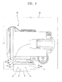
- FIG. 3 is a cross-sectional view illustrating the heat flow of an electronic device in FIG. 2
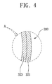
- FIG. 4 is an enlarged cross-sectional view of the part 'A' in FIG. 2
- FIG. 5 is a bottom view of the electronic device from the direction 'B' in FIG. 2 .
- a heat radiating structure 300 for an electronic module 20 in accordance with the exemplary embodiment releases heat from the electronic module 20 (i.e., a projector module 20 as an exemplary embodiment of the present invention, which will be hereinafter referred to as 'projector module 20') to the outside.
- the heat radiating structure 300 of the invention is preferably installed on an outside of the projector module 20, for example, the bottom of the projector module 20.
- the heat radiating structure 300 includes an impact absorber 310 and a heat radiating sheet 320 formed at one outer surface of the projector module 310, particularly, the bottom of the projector module 20 by covering the outer surfaces of the impact absorber 310.
- the heat radiating structure 300 in accordance with the present invention may be performed with a heat radiating sheet 320 only. It is also within the spirit of the claimed invention that the impact absorber and the heat radiating sheet may be comprised of a same or similar material.
- the impact absorber 310 functions to absorb the transferred impact from the outside, for example, the transferred impact from the case 10 of the electronic device, such as, for example, a cellular phone.
- the impact absorber 310 can be made of the high density urethane foam Poron TM produced by INOAC Corporation of Japan, which can shrink and relax with excellent impact absorption.
- the heat radiating sheet 320 is comprised of a metal sheet 323 and a graphite sheet 321, the metal sheet 323 will be formed at the outside of the impact absorber 310 and the graphite sheet 321 will be formed on one side of the projector module 20.
- a projector module 20 in accordance with an exemplary embodiment can be fixed onto the case of the electronic device by, for example, a screw as shown in FIGS. 2 and 3 , for example, at the bottom of the cellular phone case 10.
- a screw as shown in FIGS. 2 and 3
- any known fastening arrangement can be used in accordance with the claimed invention.
- the heat radiating structure 300 in accordance with the present invention releases heat from the projector module 20 to the outside by being connected to an outside surface of the projector module 20, which is not affixed onto the cellular phone case 10.
- the heat radiating structure 300 can be formed between the one side of the cellular phone case 10, where the projector module 20 is fixed, and the outer surface of the projector module 20, which is opposing the one side of the cellular phone case 10; and the generated heat can be released from the projector module 20 in the direction of the cellular phone case 10.
- the heat radiating structure 300 in accordance with the present invention includes the impact absorber 310.
- the impact absorber 310 in the heat radiating structure 300 can absorb the transferred impact from the outside, for example, the impact transferred from the one side of the cellular phone case 10.
- a projection unit 21, which includes a display unit 22 and an optical unit 23 therein, generates comparatively less heat than, for example a lighting unit.
- a lighting unit 25, which include an LED 26 as a light source and a substrate 27 with the LED 26 mounted thereon, and generates comparatively more heat than the projection unit 21.
- FIG. 6 is a perspective view of an electronic device having a heat radiating structure for an electronic module in accordance with another exemplary embodiment of the presently claimed invention.
- the heat radiating structure 300a in accordance with this particular exemplary embodiment includes an impact absorber 310; a heat radiating sheet 320, which covers the outside of the impact absorber 310 and is in contact with one outer surface, particularly, the bottom of the projector module 20; a heat conductive plate 330, which is formed on one side of the projector module 20 adjacent to the bottom so as to transfer heat from the side of the projector module 20 to the heat radiating sheet 320.
- the impact absorber 310 absorbs impact transferred from the outside, for example, the impact transferred from the case 10 of a cellular phone.
- the impact absorber 310 can be arranged, for example, between one side of the cellular phone case 10, where the projector module 20 is installed, and one surface of the projector module 20, which the cellular phone case is contacting. On this arranged position, the impact absorber 310 can absorb the transferred impact from the outside, for example, one side of the cellular phone case 10.
- the impact absorber 310 can be made of, for example, high-density urethane foam Poron TM material produced by the Japanese INOAC Corporation, which can shrink and relax with excellent impact absorption.
- the heat radiating sheet 320 may be comprised of a plurality of the multi-layered heat conductive sheets and these multi-layered heat conductive sheets can be made of the different types of conductive sheets and/or have different characteristics.
- the plurality of the multi-layered heat sheets can be formed with a plurality of the double-layered heat conductive sheets and these heat conductive sheets can be comprised of the metal sheet 323, which is made of copper material, and the graphite sheet 321, which is stacked on the metal sheet 323.
- the heat radiating sheet can cover the impact absorber 310 by forming the edges as round shape. In this case, even if the impact absorber 310 covered by the heat radiating sheet 320 is freely shrunk and relaxed, the edges of the heat radiating sheet 320 will not be torn up.
- the heat conductive plate 330 may include a first contact part 331 in contact with the side surface of the lighting unit 25, which is a heavy heat generating part; and a second contact part 333 in contact with the heat radiating sheet 320.
- the heat conductive plate 330 can be formed as 'L' shape or horizontally-mirrored 'L' shape.
- the first contact part 331 can be formed in parallel with the side of the lighting unit 25 so as to be in contact with the side of the lighting unit 25, and the second contact part 333 can be bent into the body of the projector module 20 from the edge of the first contact part 331 so as to overlap the heat radiating sheet 320 with a certain size.
- the heat generated from the lighting unit 25, which comprises a heavy heat generating part can be transferred to the heat radiating sheet 320 through the heat conductive plate 330 in contact with the lighting unit 25 and the heat radiating unit 320, and the heat can be released to the outside by continuously transferring to the cellular phone case 10 via the heat radiating sheet 320.
- the size of the contacting area needs to be limited to the proper size to effectively dissipate the generated heat from the lighting unit 25.
- the area of the second contact part 333 (W x L in FIG. 6 ), that is, the contacting area where the heat conductive plate 330 and the heat radiating sheet 320 are touching can be made of, for example, 1 cm 2 per 1W according to the power that the LED 26 consumes to generate lighting.
- the aforementioned ratio has been provided for explanatory purposes, and the claimed invention is in no limited to the aforementioned quantities.
- FIG. 7 is a cross-sectional view illustrating an electronic device having a heat radiating structure for an electronic module in accordance with a further exemplary embodiment of the present invention.
- a heat radiating structure 300b in accordance with a further exemplary embodiment can be formed to be in contact with at least one of either the bottom of the projector module 20 or the adjacent side surface, and may include a heat radiating sheet 320a comprised of a plurality of the multi-layered heat conductive sheets; and a impact absorber 310, which is formed between the heat radiating sheet 320a and the bottom of the projector module 20 so as to absorb impact transferred from the outside.
- the heat radiating sheet 320a can include a first contact part 324 formed at the bottom of the projector module 20; a second contact part 326 formed at the side of the projector module 20; and a buffer unit 325 (C portion in FIG. 7 ) formed between the first contact part 324 and the second contact part 326.
- the shape of the impact absorber 310 may be changed by the impact to the projector module 20 from the outside, those contact parts 324 and 326 maintain the contacts, and the heat radiating structure 300b continues to operate as designed since there is the buffer unit 325 inside the heat radiating sheet 320a.
- the plurality of the heat conductive sheets can be comprised of the different heat conductive sheets, for example, which include a metal sheet 323 made of the copper material; and a graphite sheet 321 stacked on the metal sheet 323.
- at least one of the side surfaces of the projector module 20 in contact with the heat radiating sheet 320 can be the side surface of the heavy heat generating part, for example, the side surface of the lighting unit 25.
- the impact absorber 310 can be made of Poron material.
Landscapes
- Physics & Mathematics (AREA)
- Thermal Sciences (AREA)
- Engineering & Computer Science (AREA)
- Microelectronics & Electronic Packaging (AREA)
- Cooling Or The Like Of Electrical Apparatus (AREA)
- Cooling Or The Like Of Semiconductors Or Solid State Devices (AREA)
Abstract
Description
- The present invention relates to a heat radiating structure for an electronic module and an electronic device having the same. More particularly, the present invention relates to a heat radiating structure which can quickly release heat from the electronic module outside, and for an electronic device having the same structure thereon.
- In accordance with the recent development of the overall industrial technologies, multi-functional electronic devices with superb quality have been continuously introduced these days.
- Not only are the electronic devices of excellent quality and contain more multifunction capability than ever before, but such electronic devices also have been getting smaller and light-weighted. The reduced size and weight facilitates portability. However the reduced size introduces problems with heat release because of the high temperature generated form the densely packed components.
- For example, the cellular phone is one of the most popularized electronic devices and has been upgraded with more superb qualities and multi-functions despite its increasingly minimized size and weight. Therefore, it is very easy for the user to carry and keep the cellular phone.
- A plurality of the components are densely packed to fit in the thinner and smaller space of the cellular phone for better quality and multi-functionality than ever before. When high temperature is generated from one or more of the components inside, it is very difficult to dissipate generated high temperature to the outside of the cell phone.
- Especially when the electronic modules, such as a projector module, which generates lots of heat, are installed inside the cell phone and are generating a great deal of heat during operation, the heat-release problem is getting worse.
- To solve this kind of heat-release problem, the electronic devices having a heat radiating structure for releasing heat from an electronic module have been introduced.
-
FIG. 1 is a plan view of a prior art electronic device with a heat radiating structure for an electronic module. Referring now toFIG. 1 , as an example of the electronic module of the prior art, aprojector module 20 is installed inside the case of the electronic device like acell phone case 10. - The
projector module 20 includes aprojection unit 21, which generates comparatively less heat, and alighting unit 25, which generates comparatively lots of heat. Theprojection unit 21 includes adisplay unit 22 and anoptical unit 23, and thelighting unit 25 includes anLED 26 as a light source and asubstrate 27 formed with anLED 26 thereon. - Still referring to
FIG. 1 , a heat radiating structure for anelectronic module 30 includes aheat transfer plate 31 formed to transfer heat from theprojector module 20 to the outside by lengthening one side of the heavy heat generating part (hereinafter called as 'heavy heat generating part') to the exterior for a certain distance; and aheat insulating plate 33 formed at the other side of the heavy heat generating part in order not to transfer the generated heat from the heavy heat generating part of theprojector module 20 to the inside of theprojector module 20, where the other components are installed. - Accordingly, the
heat transfer plate 31 is installed on one side of thelighting unit 25, which is the heavy heat generating part, by extending from one side of thelighting unit 25 to the exterior for a certain distance, and theheat insulating plate 33 is arranged in the other side of thelighting unit 25. - As shown in
FIG. 1 , the heat generated from the heavy heat generating part of the electronic module, which originated from thelighting unit 25 of theprojector module 20, cannot be transferred to the inside, where the other components are arranged, by theheat insulating plate 33. It can be transferred outside only through theheat transfer plate 31. Thus, some of the heat release problems from the electronic devices are partially resolved by the structure shown inFIG. 1 . - Despite the above-mentioned advantages of the device shown in
FIG. 1 , there are still various disadvantages as discussed below with the heat radiating structure for anelectronic module 30 and the electronic device having the same heat radiating structure. - Firstly, because the
heat transfer plate 31 of the heat radiating structure for anelectronic module 30 show inFIG. 1 is installed on one side of thelighting unit 25, which is the heavy heat generating part, by extending from one side of thelighting unit 25 to the outside for a certain distance, there is a problem in that the heat transfer plate occupies a significant amount of space of the electronic device. As previously mentioned, the latest trend is to minimize the size and the weight of the electronic devices, and most of the components are getting smaller and arranged in a compact space. However, the above-mentioned configure of theheat transfer plate 31 is against the trend as the size might even have to be enlarged in order to efficiently transfer heat from the electronic device. - Secondly, the heat radiating structure for an
electronic module 30 shown inFIG. 1 is comprises theheat insulating plate 33, which prevents the heat from thelighting unit 25 from being transferred into the inside components; and theheat transfer plate 31 that transfers the heat from thelighting unit 25 to the outside. It is advantageous that the heat generated from thelighting unit 25 can be only transferred to the outside except the inside where the other components are installed. However, there will be a large difference in temperature between the inside and the outside of theheat insulating plate 33 because of the above-mentioned function of theheat insulating plate 33. Consequently, it may cause thesubstrate 27 of thelighting unit 25 to bend or twist and thus adversely change the alignment of theLED 26 formed on thesubstrate 27. - In case of the
projector module 20 installed on electronic devices such as shown inFIG. 1 , the alignment of theLED 26 as a light source of thelighting unit 25 may be changed so as to cause a problem of improper operation. - The present invention provides a heat radiating structure for an electronic module and the electronic device having the same structure, in which the heat radiating function efficiently operates, and the minimized size and the weight is favorably reviewed by consumers.
- The present invention is also directed to a heat radiating structure for an electronic module and the electronic device having the same structure, in which the temperature differences inside the electronic module will be resolved in advance, thereby preventing many problems that were heretofore part of conventional structures.
- The present invention also provides a heat radiating structure for an electronic module and the electronic device having the same structure, in which the generated heat from the electronic module will be dissipated outside; and by absorbing the impact from the outside, the impact of the heat will be minimized or blocked before it reaches the electronic module.
- According to an exemplary aspect of the present invention, there is provided a heat radiating structure for an electronic module. The exemplary heat radiating structure can include a heat radiating sheet formed in contact with at least one of outside surfaces of the electronic module to dissipate heat from the electronic module to the outside, the heat radiating sheet comprised of a plurality of multi-layered heat conductive sheets.
- In another exemplary aspect of the present invention, a plurality of the heat conductive sheets may include a metal sheet and a graphite sheet layered on the metal sheet. Here, the metal sheet can be made of, for example, a copper material.
- In a further exemplary aspect of the present invention, the heat radiating structure of the invention may further include an impact absorber installed between the heat radiating sheet and an outside surface of the electronic module so as to absorb impacts from outside. Here, the metal sheet can be made of, for example, a copper material.
- According to another exemplary aspect of the present invention, there is provided a heat radiating structure for an electronic module. The heat radiating structure includes a heat radiating sheet formed in contact with at least one of a bottom surface and side surfaces of the electronic module, the side surfaces placed adjacent to the bottom surface, in order to dissipate heat from the electronic module to outside, the heat radiating sheet comprised of a plurality of multi-layered heat conductive sheets.
- In yet another exemplary aspect of the present invention, a plurality of the heat conductive sheet may include a metal sheet and a graphite sheet layered on the metal sheet.
- In a further exemplary aspect of the invention, at least one of the side surfaces of the electronic module in contact with the heat radiating sheet may comprise a side surface of a heavy heat generating part of the electronic module, which mainly generates heat.
- In still another exemplary aspect of the present invention, the heat radiating structure of the invention may further include an impact absorber installed between the heat radiating sheet and the bottom surface of the electronic module to absorb impacts from outside. Here, the metal sheet can be made of, for example, a copper material.
- According to a further exemplary aspect of the present invention, there is provided a heat radiating structure for an electronic module. The heat radiating structure dissipates heat from the electronic module to outside, and includes an impact absorber for absorbing outside impact; and a heat radiating sheet formed with a plurality of the multi-layered heat conductive sheets and contacting a bottom surface of the electronic module by covering outside of the impact absorber. The impact absorber can be made of, for example, a copper material.
- In a further exemplary aspect of the present invention, a plurality of the heat conductive sheets may include a metal sheet and a graphite sheet layered on the metal sheet.
- The heat radiating structure of the present invention, for example, may further include a heat conductive plate formed on a side surface of the electronic module adjacent to the bottom surface to transfer heat from the side surface of the electronic module to the heat radiating sheet. Here, the side surface of the electronic module in contact with the heat transfer plate can be a side surface of a heavy heat generating part of the electronic module, which mainly generates heat. In this case, the heat conductive plate can include a first contact part in contact with the side surface of the heavy heat generating part and a second contact part in contact with the heat radiating sheet, and the second contact part can be piled up on the heat radiating sheet.
- According to still another exemplary aspect of the present invention, there is provided an electronic device, which includes a case; an electronic module which is fixed on a side of the case; and a heat radiating structure for an electronic module formed in contact with at least one of sides of the electronic module in order to dissipate heat from the electronic module to outside. The heat radiating structure comprises a heat radiating sheet comprised of a plurality of multi-layered heat conductive sheets.
- The heat radiating sheet, for example, may be installed between the side of the case, where the electronic module is fixed, and an outside surface of the electronic module, which is opposite to the side of the case.
- In addition, the heat radiating structure for an electronic module may further include an impact absorber formed between the heat radiating sheet and the surface of the electronic module to absorb impacts from outside.
- In still another exemplary aspect of the present invention, a plurality of the heat conductive sheet may include a metal sheet and a graphite sheet layered on the metal sheet.
- According to the present invention, the heat radiating structure for an electronic module may include a heat radiating sheet comprised of a plurality of the heat conductive sheets. Using the heat radiating structure for an electronic module in accordance with the present invention makes it possible not only to perform the heat release function but also to correspond with the trends for the minimization of the size and the weight.
- Since the heat radiating structure for an electronic module of the present invention is formed without the heat insulating plate of the prior art, it is possible to solve the problems with the partial temperature differences caused by the heat insulating plate, and the other points at issue in advance.
- Furthermore, the heat radiating structure for an electronic module according to the present invention can more include impact absorbers that absorb the impacts from outside. Using the heat radiating structure for the electronic module in accordance with the present invention makes it possible not only to dissipate the generated heat from the electronic module to the outside but also to block or minimize the impact from the outside and thereby not being transferred to the electronic module by absorbing it.
- The above and other exemplary objects, features and other advantages of the present invention will be more clearly understood from the following detailed description taken in conjunction with the accompanying drawings, in which:
-
FIG. 1 is a plan view of illustrating an electronic device having a heat radiating structure for an electronic module of the prior art; -
FIG. 2 is a cross-sectional view of an electronic device having a heat radiating structure for an electronic module in accordance with an exemplary embodiment of the invention; -
FIG. 3 is a cross-sectional view illustrating the heat flow of an electronic device inFIG. 2 ; -
FIG. 4 is an enlarged cross-sectional view of the part 'A' inFIG. 2 ; -
FIG. 5 is a bottom view of the electronic device from the direction 'B' inFIG. 2 ; -
FIG. 6 is a perspective view of an electronic device having a heat radiating structure for an electronic module in accordance with another exemplary embodiment; and -
FIG. 7 is a cross-sectional view illustrating an electronic device having a heat radiating structure for an electronic module in accordance with a further exemplary embodiment. - Hereinafter, exemplary embodiments of the invention provided solely for illustrative purposes will be described in detail with reference to the accompanying drawings. A projector module will be described as an exemplary embodiment of the electronic module, and a cellular phone will be described as an exemplary embodiment of the electronic device. However, the present invention is not limited to the exemplary embodiments described herein and various changes or features may be made in the functions and arrangement of the elements that are within the spirit of the invention and the scope of the appended claims. With regard to the drawings, the same reference numerals and signs are used throughout the different drawings to designate the same or similar components.
-
FIG. 2 is a side cross-sectional view of an electronic device having a heat radiating structure for an electronic module according to an exemplary embodiment of the present invention.FIG. 3 is a cross-sectional view illustrating the heat flow of an electronic device inFIG. 2 ,FIG. 4 is an enlarged cross-sectional view of the part 'A' inFIG. 2 , andFIG. 5 is a bottom view of the electronic device from the direction 'B' inFIG. 2 . - Referring now to the examples in
FIGS. 2 to 5 , aheat radiating structure 300 for anelectronic module 20 in accordance with the exemplary embodiment releases heat from the electronic module 20 (i.e., aprojector module 20 as an exemplary embodiment of the present invention, which will be hereinafter referred to as 'projector module 20') to the outside. Theheat radiating structure 300 of the invention is preferably installed on an outside of theprojector module 20, for example, the bottom of theprojector module 20. In this example, theheat radiating structure 300 includes animpact absorber 310 and aheat radiating sheet 320 formed at one outer surface of theprojector module 310, particularly, the bottom of theprojector module 20 by covering the outer surfaces of theimpact absorber 310. However, theheat radiating structure 300 in accordance with the present invention may be performed with aheat radiating sheet 320 only. It is also within the spirit of the claimed invention that the impact absorber and the heat radiating sheet may be comprised of a same or similar material. - Still referring to
FIGs. 2 to 5 , theimpact absorber 310 functions to absorb the transferred impact from the outside, for example, the transferred impact from thecase 10 of the electronic device, such as, for example, a cellular phone. Theimpact absorber 310 can be made of the high density urethane foam Poron™ produced by INOAC Corporation of Japan, which can shrink and relax with excellent impact absorption. - The
heat radiating sheet 320 may comprise a plurality of multi-layered heat conductive sheets. At least some of the multiple heat conductive sheets can be respectively comprised of different types of heat conductive sheets. A plurality of the multi-layered heat conductive sheets may comprise a plurality of double-layered heat conductive sheets, such as shown inFIGS. 2 to 4 . The heat conductive sheets may also be comprised of, for example, a metal sheet 323 (shown inFIG. 4 ) which is comparatively high conductive, and agraphite sheet 321, which is more conductive than themetal sheet 323 and can be piled on themetal sheet 323. Themetal sheet 323 may be made of, for example, a copper material. When theheat radiating sheet 320 is comprised of ametal sheet 323 and agraphite sheet 321, themetal sheet 323 will be formed at the outside of theimpact absorber 310 and thegraphite sheet 321 will be formed on one side of theprojector module 20. - As shown in
FIGs. 2 and3 , in theheat radiating sheet 320 covering the surface of theimpact absorber 310, the edges can be rounded. Even if theimpact absorber 310 covered by theheat radiating sheet 320 are freely shrunk and relaxed, the edges of theheat radiating sheet 320 will not be torn up. - On the other hand, a
projector module 20 in accordance with an exemplary embodiment can be fixed onto the case of the electronic device by, for example, a screw as shown inFIGS. 2 and3 , for example, at the bottom of thecellular phone case 10. However, it should be understand that any known fastening arrangement can be used in accordance with the claimed invention. - In this particular example, the
heat radiating structure 300 in accordance with the present invention releases heat from theprojector module 20 to the outside by being connected to an outside surface of theprojector module 20, which is not affixed onto thecellular phone case 10. However, theheat radiating structure 300 can be formed between the one side of thecellular phone case 10, where theprojector module 20 is fixed, and the outer surface of theprojector module 20, which is opposing the one side of thecellular phone case 10; and the generated heat can be released from theprojector module 20 in the direction of thecellular phone case 10. - Moreover, the
heat radiating structure 300 in accordance with the present invention includes theimpact absorber 310. When theheat radiating structure 300 is formed between one side of the fixedcellular phone case 10 and the outer surface of theprojector module 20, which is in contact with the one side of thecase 10, theimpact absorber 310 in theheat radiating structure 300 can absorb the transferred impact from the outside, for example, the impact transferred from the one side of thecellular phone case 10. - Referring to
FIGs. 2 and3 , aprojection unit 21, which includes adisplay unit 22 and anoptical unit 23 therein, generates comparatively less heat than, for example a lighting unit. Alighting unit 25, which include anLED 26 as a light source and asubstrate 27 with theLED 26 mounted thereon, and generates comparatively more heat than theprojection unit 21. -
FIG. 6 is a perspective view of an electronic device having a heat radiating structure for an electronic module in accordance with another exemplary embodiment of the presently claimed invention. - Referring to
FIG. 6 , theheat radiating structure 300a in accordance with this particular exemplary embodiment includes animpact absorber 310; aheat radiating sheet 320, which covers the outside of theimpact absorber 310 and is in contact with one outer surface, particularly, the bottom of theprojector module 20; a heatconductive plate 330, which is formed on one side of theprojector module 20 adjacent to the bottom so as to transfer heat from the side of theprojector module 20 to theheat radiating sheet 320. - The
impact absorber 310 absorbs impact transferred from the outside, for example, the impact transferred from thecase 10 of a cellular phone. Theimpact absorber 310 can be arranged, for example, between one side of thecellular phone case 10, where theprojector module 20 is installed, and one surface of theprojector module 20, which the cellular phone case is contacting. On this arranged position, theimpact absorber 310 can absorb the transferred impact from the outside, for example, one side of thecellular phone case 10. Theimpact absorber 310 can be made of, for example, high-density urethane foam Poron™ material produced by the Japanese INOAC Corporation, which can shrink and relax with excellent impact absorption. - The
heat radiating sheet 320 may be comprised of a plurality of the multi-layered heat conductive sheets and these multi-layered heat conductive sheets can be made of the different types of conductive sheets and/or have different characteristics. For example, the plurality of the multi-layered heat sheets can be formed with a plurality of the double-layered heat conductive sheets and these heat conductive sheets can be comprised of themetal sheet 323, which is made of copper material, and thegraphite sheet 321, which is stacked on themetal sheet 323. The heat radiating sheet can cover theimpact absorber 310 by forming the edges as round shape. In this case, even if theimpact absorber 310 covered by theheat radiating sheet 320 is freely shrunk and relaxed, the edges of theheat radiating sheet 320 will not be torn up. - Still referring to
FIG. 6 , one side surface of theprojector module 20 in contact with the heatconductive plate 330 may be the side surface of the heavy heat generating part of theprojector module 20, for example, the side surface of thelighting unit 25, which generates lots of heat. - The heat
conductive plate 330 may include afirst contact part 331 in contact with the side surface of thelighting unit 25, which is a heavy heat generating part; and asecond contact part 333 in contact with theheat radiating sheet 320. The heatconductive plate 330 can be formed as 'L' shape or horizontally-mirrored 'L' shape. At this time, thefirst contact part 331 can be formed in parallel with the side of thelighting unit 25 so as to be in contact with the side of thelighting unit 25, and thesecond contact part 333 can be bent into the body of theprojector module 20 from the edge of thefirst contact part 331 so as to overlap theheat radiating sheet 320 with a certain size. - Therefore, the heat generated from the
lighting unit 25, which comprises a heavy heat generating part, can be transferred to theheat radiating sheet 320 through the heatconductive plate 330 in contact with thelighting unit 25 and theheat radiating unit 320, and the heat can be released to the outside by continuously transferring to thecellular phone case 10 via theheat radiating sheet 320. - In the mean time, in order to more efficiently transfer and radiate the generated heat from the
lighting unit 25 to theheat radiating sheet 320, the area (W x L inFIG. 6 ) of thesecond contact part 333, that is, the contactarea (i.e. where the heatconductive plate 330 and theheat radiating sheet 320 are touching each) other needs to be large enough to dissipate the heat generated from thelighting unit 25, particularly, the heat from theLED 26. When the contact area is too large, the sizes of theprojector module 20 having the heatconductive plate 330 and the cellular phone having the same module may go against the latest trend of minimizing the size and the weight. Therefore, the size of the contacting area needs to be limited to the proper size to effectively dissipate the generated heat from thelighting unit 25. For example, the area of the second contact part 333 (W x L inFIG. 6 ), that is, the contacting area where the heatconductive plate 330 and theheat radiating sheet 320 are touching can be made of, for example, 1 cm2 per 1W according to the power that theLED 26 consumes to generate lighting. The aforementioned ratio has been provided for explanatory purposes, and the claimed invention is in no limited to the aforementioned quantities. -
FIG. 7 is a cross-sectional view illustrating an electronic device having a heat radiating structure for an electronic module in accordance with a further exemplary embodiment of the present invention. - As shown in
FIG. 7 , aheat radiating structure 300b in accordance with a further exemplary embodiment can be formed to be in contact with at least one of either the bottom of theprojector module 20 or the adjacent side surface, and may include aheat radiating sheet 320a comprised of a plurality of the multi-layered heat conductive sheets; and aimpact absorber 310, which is formed between theheat radiating sheet 320a and the bottom of theprojector module 20 so as to absorb impact transferred from the outside. - Still referring to the example shown in
FIG. 7 , theheat radiating sheet 320a can include afirst contact part 324 formed at the bottom of theprojector module 20; asecond contact part 326 formed at the side of theprojector module 20; and a buffer unit 325 (C portion inFIG. 7 ) formed between thefirst contact part 324 and thesecond contact part 326. - According to the present invention, even though the shape of the
impact absorber 310 may be changed by the impact to theprojector module 20 from the outside, thosecontact parts heat radiating structure 300b continues to operate as designed since there is thebuffer unit 325 inside theheat radiating sheet 320a. - At this point, if the shape and structure of the
buffer unit 325 prevents theheat radiating sheet 320a from changing its shape despite the outside impact, it is possible to be form the buffer unit to comprise various shapes and structures. For example, the shape and structure of thebuffer unit 325 can be formed as the shoulder structure, such as, for example, a mountain peak as shown inFIG. 7 . - The plurality of the heat conductive sheets can be comprised of the different heat conductive sheets, for example, which include a
metal sheet 323 made of the copper material; and agraphite sheet 321 stacked on themetal sheet 323. Moreover, at least one of the side surfaces of theprojector module 20 in contact with theheat radiating sheet 320 can be the side surface of the heavy heat generating part, for example, the side surface of thelighting unit 25. Furthermore, theimpact absorber 310 can be made of Poron material. - While the present invention has been shown and described in connection with the preferred exemplary embodiments, it will be apparent to those skilled in the art that modifications and variations can be made without departing from the spirit and scope of the invention as defined by the appended claims.
Claims (15)
- A heat radiating structure for an electronic module, comprising:a heat radiating sheet for dissipating heat from the electronic module to an exterior, the heat radiating sheet arranged in contact with at least one of a bottom surface and side surfaces of the electronic module, characterized in that the side surfaces being adjacent the bottom surface, and the heat radiating sheet comprises a plurality of multi-layered heat conductive sheets.
- The heat radiating structure according to claim 1, characterized in that the plurality of the multi-layered heat conductive sheets includes a metal sheet and a graphite sheet layered on the metal sheet.
- The heat radiating structure according to claim 1, characterized in that at least one of the side surfaces of the electronic module in contact with the heat radiating sheet comprises a side surface of a relatively heavy heat generating part of the electronic module, which mainly generates heat.
- The heat radiating structure according to claim 1, further comprising an impact absorber for absorbing impact from an exterior of the electronic module, said impact absorber arranged between the heat radiating sheet and the bottom surface of the electronic module.
- The heat radiating structure according to claim 4, characterized in that the impact absorber comprises a urethane polymer.
- A heat radiating structure for an electronic module, comprising:an impact absorber for absorbing exterior impact; anda heat radiating sheet for dissipating heat from the electronic module to an exterior, the heat radiating sheet comprising a plurality of multi-layered heat conductive sheets and in contact with a bottom surface of the electronic module by covering an outer surface of the impact absorber.
- The heat radiating structure according to claim 6, characterized in that the impact absorber comprises a urethane polymer.
- The heat radiating structure according to claim 6, characterized in that the plurality of the multi-layered heat conductive sheets includes a metal sheet and a graphite sheet layered on the metal sheet.
- The heat radiating structure according to claim 6, further comprising a heat conductive plate formed on a side surface of the electronic module adjacent the bottom surface for transferring heat from the side surface of the electronic module to the heat radiating sheet.
- The heat radiating structure according to claim 9, characterized in that the side surface of the electronic module in contact with the heat transfer plate comprises a side surface of a heavy heat generating part of the electronic module, which mainly generates heat.
- The heat radiating structure according to claim 10, characterized in that the heat conductive plate includes a first contact part in contact with the side surface of the heavy heat generating part and a second contact part in contact with the heat radiating sheet, and
wherein the second contact part is arranged on the heat radiating sheet. - An electronic device comprising:a case;an electronic module which is fixed on a side of the case, said electronic module having a plurality of sides; anda heat radiating structure for an electronic module formed in contact with at least one side of the plurality of sides of the electronic module in order to dissipate heat from the electronic module to an exterior,wherein the heat radiating structure comprises a heat radiating sheet comprised of a plurality of multi-layered heat conductive sheets.
- The electronic device according to claim 12, wherein the heat radiating sheet is arranged between the side of the case, where the electronic module is fixed, and an outer surface of the electronic module, which is opposite to the side of the case.
- The electronic device according to claim 13, characterized in that the heat radiating structure for an electronic module further comprises an impact absorber arranged between the heat radiating sheet and the surface of the electronic module to absorb impacts from outside of the electronic module.
- The electronic device according to claim 12, wherein the plurality of multi-layered heat conductive sheet includes a metal sheet and a graphite sheet layered on the metal sheet.
Applications Claiming Priority (1)
| Application Number | Priority Date | Filing Date | Title |
|---|---|---|---|
| KR1020080005407A KR101420802B1 (en) | 2008-01-17 | 2008-01-17 | HEATING STRUCTURE FOR ELECTRONIC MODULE AND ELECTRONIC DEVICE HAVING THE SAME |
Publications (3)
| Publication Number | Publication Date |
|---|---|
| EP2081421A2 true EP2081421A2 (en) | 2009-07-22 |
| EP2081421A3 EP2081421A3 (en) | 2010-01-13 |
| EP2081421B1 EP2081421B1 (en) | 2011-08-03 |
Family
ID=40600362
Family Applications (1)
| Application Number | Title | Priority Date | Filing Date |
|---|---|---|---|
| EP08172047A Not-in-force EP2081421B1 (en) | 2008-01-17 | 2008-12-18 | Heat Radiating Structure for Electronic Module and Electronic Device having the Same |
Country Status (4)
| Country | Link |
|---|---|
| US (1) | US7965515B2 (en) |
| EP (1) | EP2081421B1 (en) |
| KR (1) | KR101420802B1 (en) |
| CN (1) | CN101489370B (en) |
Cited By (1)
| Publication number | Priority date | Publication date | Assignee | Title |
|---|---|---|---|---|
| WO2019131018A1 (en) * | 2017-12-26 | 2019-07-04 | Shin-Etsu Polymer Co., Ltd. | Heat dissipating structure and battery provided with the same |
Families Citing this family (4)
| Publication number | Priority date | Publication date | Assignee | Title |
|---|---|---|---|---|
| EP2540085A1 (en) * | 2010-02-26 | 2013-01-02 | Graftech International Holdings Inc. | Thermal management for handheld projectors |
| CN103533805A (en) * | 2012-07-05 | 2014-01-22 | 苏州沛德导热材料有限公司 | Polymer graphite three-dimensional heat conduction device |
| KR102122450B1 (en) * | 2016-08-26 | 2020-06-12 | 주식회사 엘지화학 | Materail for radiating heat and method for producing the material and battery module having the same |
| KR102763745B1 (en) * | 2019-04-04 | 2025-02-13 | 삼성전자주식회사 | Electronic device with heat-radiant structure |
Family Cites Families (27)
| Publication number | Priority date | Publication date | Assignee | Title |
|---|---|---|---|---|
| US4997032A (en) * | 1987-09-25 | 1991-03-05 | Minnesota Mining And Manufacturing Company | Thermal transfer bag |
| US5000256A (en) * | 1990-07-20 | 1991-03-19 | Minnesota Mining And Manufacturing Company | Heat transfer bag with thermal via |
| US6657858B2 (en) * | 1997-10-25 | 2003-12-02 | Philon Rothschild | Housing for data storage devices or for accommodating such devices |
| US20020097556A1 (en) * | 2001-01-25 | 2002-07-25 | Jui-Ju Lee | Shockproof device of a hard disk drive |
| JP4706125B2 (en) * | 2001-05-24 | 2011-06-22 | パナソニック株式会社 | Information processing device with heat dissipation buffer structure for functional unit |
| US6946190B2 (en) * | 2002-02-06 | 2005-09-20 | Parker-Hannifin Corporation | Thermal management materials |
| AU2003225797A1 (en) * | 2002-03-13 | 2003-09-29 | Tiqit Computers, Inc. | Computer assembly for facilitating heat dissipation |
| US6765793B2 (en) | 2002-08-30 | 2004-07-20 | Themis Corporation | Ruggedized electronics enclosure |
| US7168484B2 (en) * | 2003-06-30 | 2007-01-30 | Intel Corporation | Thermal interface apparatus, systems, and methods |
| US7009835B2 (en) * | 2003-07-16 | 2006-03-07 | Olixir Technologies Corp. | Energy dissipative device and method |
| US20080131655A1 (en) * | 2006-03-21 | 2008-06-05 | Barbara Wacker | Double Layer Carbon Nanotube-Based Structures and Methods for Removing Heat from Solid-State Devices |
| US20080131722A1 (en) * | 2006-03-21 | 2008-06-05 | Ephraim Suhir | Single Layer Carbon Nanotube-Based Structures and Methods for Removing Heat from Solid-State Devices |
| JP2005210035A (en) * | 2004-01-26 | 2005-08-04 | Otsuka Denki Kk | Graphite composite material |
| KR100696465B1 (en) * | 2003-11-25 | 2007-03-19 | 삼성에스디아이 주식회사 | Plasma display device |
| US7679145B2 (en) * | 2004-08-31 | 2010-03-16 | Intel Corporation | Transistor performance enhancement using engineered strains |
| US7393587B2 (en) * | 2004-09-17 | 2008-07-01 | Graftech International Holdings Inc. | Sandwiched finstock |
| US7345845B2 (en) * | 2004-09-30 | 2008-03-18 | Hitachi Global Storage Technologies Netherlands B.V. | Fluid damping structure for hard disk drives and vibration sensitive electronic devices |
| US20060077638A1 (en) * | 2004-10-12 | 2006-04-13 | Salmon Peter C | Adaptive interface using flexible fingers |
| KR100677394B1 (en) * | 2004-11-16 | 2007-02-02 | 엘지전자 주식회사 | Charging equipment having cooling pad |
| US7306847B2 (en) | 2005-01-28 | 2007-12-11 | Graftech International Holdings Inc. | Heat spreader for display device |
| JP2006336986A (en) | 2005-06-06 | 2006-12-14 | Hidetoshi Watanabe | Target device for gun toy |
| EP1746077A1 (en) * | 2005-06-21 | 2007-01-24 | Sgl Carbon Ag | Metal-coated graphite foil |
| US20070062676A1 (en) | 2005-09-20 | 2007-03-22 | Grand Power Sources Inc. | Heat sink module |
| US20070063339A1 (en) | 2005-09-21 | 2007-03-22 | Grand Power Sources Inc. | Heat dissipating assembly for heat dissipating substrate and application |
| JP2007184392A (en) * | 2006-01-06 | 2007-07-19 | Taika:Kk | Thermal conductive structure, heat dissipation member and electronic device using the same |
| US7495226B2 (en) * | 2006-05-26 | 2009-02-24 | Carestream Health, Inc. | Compact and durable encasement for a digital radiography detector |
| EP2034520B1 (en) | 2006-06-08 | 2013-04-03 | International Business Machines Corporation | Highly heat conductive, flexible sheet |
-
2008
- 2008-01-17 KR KR1020080005407A patent/KR101420802B1/en not_active Expired - Fee Related
- 2008-11-24 US US12/276,542 patent/US7965515B2/en not_active Expired - Fee Related
- 2008-12-18 EP EP08172047A patent/EP2081421B1/en not_active Not-in-force
-
2009
- 2009-01-12 CN CN200910003405XA patent/CN101489370B/en not_active Expired - Fee Related
Cited By (4)
| Publication number | Priority date | Publication date | Assignee | Title |
|---|---|---|---|---|
| WO2019131018A1 (en) * | 2017-12-26 | 2019-07-04 | Shin-Etsu Polymer Co., Ltd. | Heat dissipating structure and battery provided with the same |
| JP2020533776A (en) * | 2017-12-26 | 2020-11-19 | 信越ポリマー株式会社 | Heat dissipation structure and battery with it |
| EP3529851B1 (en) * | 2017-12-26 | 2021-04-07 | Shin-Etsu Polymer Co., Ltd. | Heat dissipating structure and battery provided with the same |
| US11495842B2 (en) | 2017-12-26 | 2022-11-08 | Shin-Etsu Polymer Co., Ltd. | Heat dissipating structure and battery provided with the same |
Also Published As
| Publication number | Publication date |
|---|---|
| KR101420802B1 (en) | 2014-07-21 |
| EP2081421B1 (en) | 2011-08-03 |
| CN101489370B (en) | 2012-06-27 |
| US7965515B2 (en) | 2011-06-21 |
| US20090185354A1 (en) | 2009-07-23 |
| EP2081421A3 (en) | 2010-01-13 |
| KR20090079449A (en) | 2009-07-22 |
| CN101489370A (en) | 2009-07-22 |
Similar Documents
| Publication | Publication Date | Title |
|---|---|---|
| KR100669754B1 (en) | Heat dissipation structure of display panel and display module having same | |
| JP6707960B2 (en) | Electronics | |
| US7639503B2 (en) | Printed circuit board and electronic apparatus | |
| JP5179746B2 (en) | Mobile terminal device | |
| US7251140B2 (en) | Display apparatus having heat dissipating structure for driver integrated circuit | |
| US20100157540A1 (en) | Fin-type heat sink and electronic device using same | |
| US7965515B2 (en) | Heat radiating structure for electronic module and electronic device having the same | |
| US20100157541A1 (en) | Heat sink and electronic device using same | |
| US20080191341A1 (en) | Electronic apparatus and semiconductor package | |
| US20150316966A1 (en) | Electronic device with improved heat dissipation | |
| CN109219307B (en) | Heat radiation structure and electronic device with same | |
| JP2018014428A (en) | Electronics | |
| US20120069522A1 (en) | Thermal module and electronic device incorporating the same | |
| US7478668B2 (en) | Heat dissipation device | |
| JP6791676B2 (en) | Fixing stand and fixing method | |
| JP2023511099A (en) | Protection circuit module using heat dissipation tapeBattery pack with heat dissipation structure | |
| KR20140142858A (en) | Heat radiating sheet | |
| JP2012129379A (en) | Radiation fin | |
| JP5361414B2 (en) | Portable electronic devices | |
| JP3698091B2 (en) | Substrate holding structure | |
| JP2019041014A (en) | Electronic device and substrate | |
| JP2014187133A (en) | Heat radiation member and electronic circuit | |
| US20110299252A1 (en) | Expansion card assembly and heat sink thereof | |
| TWI298619B (en) | Electronic devices and heat sink for preventing electromagnetic interference thereof | |
| JP4657972B2 (en) | Electronics |
Legal Events
| Date | Code | Title | Description |
|---|---|---|---|
| PUAI | Public reference made under article 153(3) epc to a published international application that has entered the european phase |
Free format text: ORIGINAL CODE: 0009012 |
|
| 17P | Request for examination filed |
Effective date: 20081218 |
|
| AK | Designated contracting states |
Kind code of ref document: A2 Designated state(s): AT BE BG CH CY CZ DE DK EE ES FI FR GB GR HR HU IE IS IT LI LT LU LV MC MT NL NO PL PT RO SE SI SK TR |
|
| AX | Request for extension of the european patent |
Extension state: AL BA MK RS |
|
| PUAL | Search report despatched |
Free format text: ORIGINAL CODE: 0009013 |
|
| AK | Designated contracting states |
Kind code of ref document: A3 Designated state(s): AT BE BG CH CY CZ DE DK EE ES FI FR GB GR HR HU IE IS IT LI LT LU LV MC MT NL NO PL PT RO SE SI SK TR |
|
| AX | Request for extension of the european patent |
Extension state: AL BA MK RS |
|
| 17Q | First examination report despatched |
Effective date: 20100602 |
|
| AKX | Designation fees paid |
Designated state(s): DE FR GB |
|
| GRAP | Despatch of communication of intention to grant a patent |
Free format text: ORIGINAL CODE: EPIDOSNIGR1 |
|
| GRAS | Grant fee paid |
Free format text: ORIGINAL CODE: EPIDOSNIGR3 |
|
| GRAA | (expected) grant |
Free format text: ORIGINAL CODE: 0009210 |
|
| AK | Designated contracting states |
Kind code of ref document: B1 Designated state(s): DE FR GB |
|
| REG | Reference to a national code |
Ref country code: GB Ref legal event code: FG4D |
|
| REG | Reference to a national code |
Ref country code: DE Ref legal event code: R096 Ref document number: 602008008581 Country of ref document: DE Effective date: 20111013 |
|
| PLBE | No opposition filed within time limit |
Free format text: ORIGINAL CODE: 0009261 |
|
| STAA | Information on the status of an ep patent application or granted ep patent |
Free format text: STATUS: NO OPPOSITION FILED WITHIN TIME LIMIT |
|
| 26N | No opposition filed |
Effective date: 20120504 |
|
| REG | Reference to a national code |
Ref country code: DE Ref legal event code: R097 Ref document number: 602008008581 Country of ref document: DE Effective date: 20120504 |
|
| REG | Reference to a national code |
Ref country code: FR Ref legal event code: PLFP Year of fee payment: 8 |
|
| REG | Reference to a national code |
Ref country code: FR Ref legal event code: PLFP Year of fee payment: 9 |
|
| REG | Reference to a national code |
Ref country code: FR Ref legal event code: PLFP Year of fee payment: 10 |
|
| PGFP | Annual fee paid to national office [announced via postgrant information from national office to epo] |
Ref country code: DE Payment date: 20191120 Year of fee payment: 12 |
|
| PGFP | Annual fee paid to national office [announced via postgrant information from national office to epo] |
Ref country code: FR Payment date: 20191122 Year of fee payment: 12 |
|
| PGFP | Annual fee paid to national office [announced via postgrant information from national office to epo] |
Ref country code: GB Payment date: 20191122 Year of fee payment: 12 |
|
| REG | Reference to a national code |
Ref country code: DE Ref legal event code: R119 Ref document number: 602008008581 Country of ref document: DE |
|
| GBPC | Gb: european patent ceased through non-payment of renewal fee |
Effective date: 20201218 |
|
| PG25 | Lapsed in a contracting state [announced via postgrant information from national office to epo] |
Ref country code: FR Free format text: LAPSE BECAUSE OF NON-PAYMENT OF DUE FEES Effective date: 20201231 |
|
| PG25 | Lapsed in a contracting state [announced via postgrant information from national office to epo] |
Ref country code: DE Free format text: LAPSE BECAUSE OF NON-PAYMENT OF DUE FEES Effective date: 20210701 Ref country code: GB Free format text: LAPSE BECAUSE OF NON-PAYMENT OF DUE FEES Effective date: 20201218 |