EP3529613B1 - System und verfahren zur kalibrierung einer zentrifuge - Google Patents
System und verfahren zur kalibrierung einer zentrifuge Download PDFInfo
- Publication number
- EP3529613B1 EP3529613B1 EP17787540.8A EP17787540A EP3529613B1 EP 3529613 B1 EP3529613 B1 EP 3529613B1 EP 17787540 A EP17787540 A EP 17787540A EP 3529613 B1 EP3529613 B1 EP 3529613B1
- Authority
- EP
- European Patent Office
- Prior art keywords
- sample
- calibration
- holder
- centre point
- calibration feature
- Prior art date
- Legal status (The legal status is an assumption and is not a legal conclusion. Google has not performed a legal analysis and makes no representation as to the accuracy of the status listed.)
- Active
Links
Images

Classifications
-
- B—PERFORMING OPERATIONS; TRANSPORTING
- B04—CENTRIFUGAL APPARATUS OR MACHINES FOR CARRYING-OUT PHYSICAL OR CHEMICAL PROCESSES
- B04B—CENTRIFUGES
- B04B5/00—Other centrifuges
- B04B5/04—Radial chamber apparatus for separating predominantly liquid mixtures, e.g. butyrometers
-
- G—PHYSICS
- G01—MEASURING; TESTING
- G01N—INVESTIGATING OR ANALYSING MATERIALS BY DETERMINING THEIR CHEMICAL OR PHYSICAL PROPERTIES
- G01N33/00—Investigating or analysing materials by specific methods not covered by groups G01N1/00 - G01N31/00
- G01N33/48—Biological material, e.g. blood, urine; Haemocytometers
- G01N33/483—Physical analysis of biological material
- G01N33/487—Physical analysis of biological material of liquid biological material
- G01N33/49—Blood
-
- A—HUMAN NECESSITIES
- A61—MEDICAL OR VETERINARY SCIENCE; HYGIENE
- A61M—DEVICES FOR INTRODUCING MEDIA INTO, OR ONTO, THE BODY; DEVICES FOR TRANSDUCING BODY MEDIA OR FOR TAKING MEDIA FROM THE BODY; DEVICES FOR PRODUCING OR ENDING SLEEP OR STUPOR
- A61M1/00—Suction or pumping devices for medical purposes; Devices for carrying-off, for treatment of, or for carrying-over, body-liquids; Drainage systems
- A61M1/36—Other treatment of blood in a by-pass of the natural circulatory system, e.g. temperature adaptation, irradiation ; Extra-corporeal blood circuits
- A61M1/3693—Other treatment of blood in a by-pass of the natural circulatory system, e.g. temperature adaptation, irradiation ; Extra-corporeal blood circuits using separation based on different densities of components, e.g. centrifuging
-
- B—PERFORMING OPERATIONS; TRANSPORTING
- B01—PHYSICAL OR CHEMICAL PROCESSES OR APPARATUS IN GENERAL
- B01D—SEPARATION
- B01D17/00—Separation of liquids, not provided for elsewhere, e.g. by thermal diffusion
- B01D17/02—Separation of non-miscible liquids
- B01D17/0217—Separation of non-miscible liquids by centrifugal force
-
- B—PERFORMING OPERATIONS; TRANSPORTING
- B01—PHYSICAL OR CHEMICAL PROCESSES OR APPARATUS IN GENERAL
- B01L—CHEMICAL OR PHYSICAL LABORATORY APPARATUS FOR GENERAL USE
- B01L3/00—Containers or dishes for laboratory use, e.g. laboratory glassware; Droppers
- B01L3/50—Containers for the purpose of retaining a material to be analysed, e.g. test tubes
- B01L3/502—Containers for the purpose of retaining a material to be analysed, e.g. test tubes with fluid transport, e.g. in multi-compartment structures
- B01L3/5027—Containers for the purpose of retaining a material to be analysed, e.g. test tubes with fluid transport, e.g. in multi-compartment structures by integrated microfluidic structures, i.e. dimensions of channels and chambers are such that surface tension forces are important, e.g. lab-on-a-chip
- B01L3/502753—Containers for the purpose of retaining a material to be analysed, e.g. test tubes with fluid transport, e.g. in multi-compartment structures by integrated microfluidic structures, i.e. dimensions of channels and chambers are such that surface tension forces are important, e.g. lab-on-a-chip characterised by bulk separation arrangements on lab-on-a-chip devices, e.g. for filtration or centrifugation
-
- B—PERFORMING OPERATIONS; TRANSPORTING
- B04—CENTRIFUGAL APPARATUS OR MACHINES FOR CARRYING-OUT PHYSICAL OR CHEMICAL PROCESSES
- B04B—CENTRIFUGES
- B04B13/00—Control arrangements specially designed for centrifuges; Program control of centrifuges
-
- B—PERFORMING OPERATIONS; TRANSPORTING
- B04—CENTRIFUGAL APPARATUS OR MACHINES FOR CARRYING-OUT PHYSICAL OR CHEMICAL PROCESSES
- B04B—CENTRIFUGES
- B04B5/00—Other centrifuges
-
- B—PERFORMING OPERATIONS; TRANSPORTING
- B04—CENTRIFUGAL APPARATUS OR MACHINES FOR CARRYING-OUT PHYSICAL OR CHEMICAL PROCESSES
- B04B—CENTRIFUGES
- B04B5/00—Other centrifuges
- B04B5/04—Radial chamber apparatus for separating predominantly liquid mixtures, e.g. butyrometers
- B04B5/0407—Radial chamber apparatus for separating predominantly liquid mixtures, e.g. butyrometers for liquids contained in receptacles
-
- G—PHYSICS
- G01—MEASURING; TESTING
- G01N—INVESTIGATING OR ANALYSING MATERIALS BY DETERMINING THEIR CHEMICAL OR PHYSICAL PROPERTIES
- G01N15/00—Investigating characteristics of particles; Investigating permeability, pore-volume or surface-area of porous materials
- G01N15/04—Investigating sedimentation of particle suspensions
- G01N15/042—Investigating sedimentation of particle suspensions by centrifuging and investigating centrifugates
-
- G—PHYSICS
- G01—MEASURING; TESTING
- G01N—INVESTIGATING OR ANALYSING MATERIALS BY DETERMINING THEIR CHEMICAL OR PHYSICAL PROPERTIES
- G01N15/00—Investigating characteristics of particles; Investigating permeability, pore-volume or surface-area of porous materials
- G01N15/04—Investigating sedimentation of particle suspensions
- G01N15/05—Investigating sedimentation of particle suspensions in blood
-
- G—PHYSICS
- G01—MEASURING; TESTING
- G01N—INVESTIGATING OR ANALYSING MATERIALS BY DETERMINING THEIR CHEMICAL OR PHYSICAL PROPERTIES
- G01N21/00—Investigating or analysing materials by the use of optical means, i.e. using sub-millimetre waves, infrared, visible or ultraviolet light
- G01N21/01—Arrangements or apparatus for facilitating the optical investigation
- G01N21/03—Cuvette constructions
- G01N21/07—Centrifugal type cuvettes
-
- G—PHYSICS
- G01—MEASURING; TESTING
- G01N—INVESTIGATING OR ANALYSING MATERIALS BY DETERMINING THEIR CHEMICAL OR PHYSICAL PROPERTIES
- G01N33/00—Investigating or analysing materials by specific methods not covered by groups G01N1/00 - G01N31/00
- G01N33/48—Biological material, e.g. blood, urine; Haemocytometers
- G01N33/483—Physical analysis of biological material
- G01N33/487—Physical analysis of biological material of liquid biological material
- G01N33/49—Blood
- G01N33/491—Blood by separating the blood components
-
- A—HUMAN NECESSITIES
- A61—MEDICAL OR VETERINARY SCIENCE; HYGIENE
- A61M—DEVICES FOR INTRODUCING MEDIA INTO, OR ONTO, THE BODY; DEVICES FOR TRANSDUCING BODY MEDIA OR FOR TAKING MEDIA FROM THE BODY; DEVICES FOR PRODUCING OR ENDING SLEEP OR STUPOR
- A61M2205/00—General characteristics of the apparatus
- A61M2205/33—Controlling, regulating or measuring
- A61M2205/3306—Optical measuring means
-
- A—HUMAN NECESSITIES
- A61—MEDICAL OR VETERINARY SCIENCE; HYGIENE
- A61M—DEVICES FOR INTRODUCING MEDIA INTO, OR ONTO, THE BODY; DEVICES FOR TRANSDUCING BODY MEDIA OR FOR TAKING MEDIA FROM THE BODY; DEVICES FOR PRODUCING OR ENDING SLEEP OR STUPOR
- A61M2205/00—General characteristics of the apparatus
- A61M2205/70—General characteristics of the apparatus with testing or calibration facilities
-
- B—PERFORMING OPERATIONS; TRANSPORTING
- B01—PHYSICAL OR CHEMICAL PROCESSES OR APPARATUS IN GENERAL
- B01L—CHEMICAL OR PHYSICAL LABORATORY APPARATUS FOR GENERAL USE
- B01L2200/00—Solutions for specific problems relating to chemical or physical laboratory apparatus
- B01L2200/06—Fluid handling related problems
- B01L2200/0621—Control of the sequence of chambers filled or emptied
-
- B—PERFORMING OPERATIONS; TRANSPORTING
- B01—PHYSICAL OR CHEMICAL PROCESSES OR APPARATUS IN GENERAL
- B01L—CHEMICAL OR PHYSICAL LABORATORY APPARATUS FOR GENERAL USE
- B01L2300/00—Additional constructional details
- B01L2300/08—Geometry, shape and general structure
- B01L2300/0803—Disc shape
-
- B—PERFORMING OPERATIONS; TRANSPORTING
- B01—PHYSICAL OR CHEMICAL PROCESSES OR APPARATUS IN GENERAL
- B01L—CHEMICAL OR PHYSICAL LABORATORY APPARATUS FOR GENERAL USE
- B01L2300/00—Additional constructional details
- B01L2300/08—Geometry, shape and general structure
- B01L2300/0861—Configuration of multiple channels and/or chambers in a single devices
- B01L2300/0864—Configuration of multiple channels and/or chambers in a single devices comprising only one inlet and multiple receiving wells, e.g. for separation, splitting
-
- B—PERFORMING OPERATIONS; TRANSPORTING
- B01—PHYSICAL OR CHEMICAL PROCESSES OR APPARATUS IN GENERAL
- B01L—CHEMICAL OR PHYSICAL LABORATORY APPARATUS FOR GENERAL USE
- B01L2400/00—Moving or stopping fluids
- B01L2400/04—Moving fluids with specific forces or mechanical means
- B01L2400/0403—Moving fluids with specific forces or mechanical means specific forces
- B01L2400/0409—Moving fluids with specific forces or mechanical means specific forces centrifugal forces
-
- G—PHYSICS
- G01—MEASURING; TESTING
- G01N—INVESTIGATING OR ANALYSING MATERIALS BY DETERMINING THEIR CHEMICAL OR PHYSICAL PROPERTIES
- G01N15/00—Investigating characteristics of particles; Investigating permeability, pore-volume or surface-area of porous materials
- G01N15/01—Investigating characteristics of particles; Investigating permeability, pore-volume or surface-area of porous materials specially adapted for biological cells, e.g. blood cells
-
- G—PHYSICS
- G01—MEASURING; TESTING
- G01N—INVESTIGATING OR ANALYSING MATERIALS BY DETERMINING THEIR CHEMICAL OR PHYSICAL PROPERTIES
- G01N15/00—Investigating characteristics of particles; Investigating permeability, pore-volume or surface-area of porous materials
- G01N15/04—Investigating sedimentation of particle suspensions
- G01N15/042—Investigating sedimentation of particle suspensions by centrifuging and investigating centrifugates
- G01N2015/045—Investigating sedimentation of particle suspensions by centrifuging and investigating centrifugates by optical analysis
- G01N2015/047—Investigating sedimentation of particle suspensions by centrifuging and investigating centrifugates by optical analysis by static multidetectors
-
- G—PHYSICS
- G01—MEASURING; TESTING
- G01N—INVESTIGATING OR ANALYSING MATERIALS BY DETERMINING THEIR CHEMICAL OR PHYSICAL PROPERTIES
- G01N15/00—Investigating characteristics of particles; Investigating permeability, pore-volume or surface-area of porous materials
- G01N15/04—Investigating sedimentation of particle suspensions
- G01N15/05—Investigating sedimentation of particle suspensions in blood
- G01N2015/055—Investigating sedimentation of particle suspensions in blood for hematocrite determination
-
- G—PHYSICS
- G01—MEASURING; TESTING
- G01N—INVESTIGATING OR ANALYSING MATERIALS BY DETERMINING THEIR CHEMICAL OR PHYSICAL PROPERTIES
- G01N21/00—Investigating or analysing materials by the use of optical means, i.e. using sub-millimetre waves, infrared, visible or ultraviolet light
- G01N21/17—Systems in which incident light is modified in accordance with the properties of the material investigated
- G01N21/59—Transmissivity
- G01N21/5907—Densitometers
- G01N2021/5969—Scanning of a tube, a cuvette, a volume of sample
- G01N2021/5973—Scanning of a tube, a cuvette, a volume of sample where the cuvette or tube is moved
Definitions
- This invention relates to a system and method for fluid analysis, and in particular relates to a system for the accurate analysis of fluids under centrifugation.
- one known technique involves placing a sample of the fluid in an elongate sample chamber of a cuvette, and rotating the cuvette in a centrifuge, such that the elongate sample chamber is arranged generally radially with respect to the axis about which the cuvette rotates.
- the heaviest components of the fluid will gather at the end of the sample chamber which is furthest the axis of rotation, while the lightest components will gather at the end of the sample chamber that is closest to the axis of rotation. In this way, fractionation of the fluid can be achieved, and the boundaries between the various components can be measured.
- a medical professional may wish to determine the proportion of red blood cells in a sample of blood, haematocrit.
- the red blood cells will (being the heaviest component of the blood) gather at the location furthest from the axis of rotation.
- the highest position of the layer of the red blood cells (edge) relative to the end of the sample chamber furthest from the axis of rotation divided by the position of the total sample height (edge) relative to the end of the sample chamber furthest from the axis of rotation can be used to indicate the proportion of red blood cells in the sample (haematocrit).
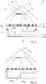
- FIG. 1 of the accompanying drawings a schematic view is shown of a conventional set up for analysing blood under these circumstances.
- a blood sample 1 is held within an elongate sample chamber S, which is subject to centrifugation.
- the blood sample 1 has separated into two separate components, namely the red blood cells 2, which have accumulated at the end of the sample chamber which is furthest from the axis of rotation A, and the remaining components 3 of the blood occupy the part of the sample chamber that is closest to the axis of rotation.
- a radiation source 4 is provided to one side of the sample chamber.
- the radiation source 4 emits a beam 5 of radiation (which may be optical frequencies of light, or any other type of radiation), which impinges on the blood sample 1.
- a sensor array 6 is provided on the far side of the blood sample 1 from the radiation source 4.
- the sensor array 6 includes a number of discrete radiation sensors, arranged along an axis which is aligned with the blood sample 1. It will be understood that the beam 5 of radiation emitted by the radiation source 4 will impinge from the blood sample 1, and to the extent that the radiation passes through the blood sample 1, this radiation will be detected by the sensors in the sensor array 6.
- the sensor array 6 may, for example, comprise a narrow, elongate charge coupled device (CCD).
- CCD charge coupled device
- FIG. 1 shows a graph representing schematically the intensity of radiation 7 detected by the sensor array 6 along its length 8.
- the radiation bypasses the blood sample 1 and impinges directly on the sensor array 6.
- the intensity of radiation detected by the sensor array 6 is low, since relatively little radiation will be transmitted through the dense red blood cells 2.
- the length of the zone 9 created by the red blood cell component (or 11b-11a) as a portion of the intensity profile created by total length of the sample i.e. the total of the two regions 9, 10 or 11c-11a
- FIG 1 shows the system of figure 1 in solid lines, with an alternative laterally dislodged position for the radiation source 4 being shown in dashed lines. It can be seen that the beam 5 of radiation produced by the radiation source 4 will also be laterally shifted as a result of this. A lateral shift in the radiation source would lead edges 11a, 11b and 11c to change with a non-linear relation to each other that would make direct indication of the proportion of red blood cells 2 in the blood sample 1 inaccurate.
- US6002474 discloses a centrifuge device that is used to centrifuge a fluid sample, such as a blood sample, to separate the fluid sample into its various component layers, and which is capable of measuring the length of the component layers to calculate cell counts for each layer.
- the centrifuge device includes a rotor assembly for rotating and thus centrifuging the fluid sample, and a movable optical reader device for reading the cell layers in the centrifuged sample.
- the centrifuge device is capable of accurately controlling the reading of the centrifuged sample based on the orientation of the rotor, so that the rotor can continue to rotate the centrifuged sample while the readings are being taken.
- WO96/17243 discloses an apparatus for analysing blood or the like, which has a centrifuge rotor with a means for visibly holding a sample, and a scanning arm which traverses the rotor and includes a means for sending light to the sample to detect the sample component interfaces.
- a second light source may be provided for colourimetric inspection of the sample.
- one aspect of the present invention provides a sample holder for use in a centrifuge, the sample holder being generally planar and comprising: an aperture or recess for releasably retaining a sample storage member including a sample chamber adapted to contain a volume of liquid; a centre point around which the holder will rotate during use; and one or more calibration features, wherein the calibration feature(s) comprise one or more outer edges, which lie on the side of the or each calibration feature which is furthest from the centre point, and the one or more outer edges comprise a series of radially spaced-apart outer edge portions or positions which are spaced at different distances from the centre point as a function of angular position around the centre point, and wherein the or each calibration feature is an aperture formed through the entire thickness of the holder, or is an insert of a transparent or substantially transparent material which is placed into a hole in the holder.
- the sample holder comprises a calibration feature having a continuous outer edge which has a plurality of outer edge portions or positions which are at varying distances from the centre point.
- the outer edge of the calibration feature is curved and the distance of the outer edge from the centre point varies continuously or substantially continuously along its length.
- the outer edge of the calibration feature comprising a series of discrete outer edge portions, each of which is at a different distance from the centre point.
- the sample holder comprises a series of individual, spaced-apart calibration features, each feature having an outer edge which is at a different distance from the centre point.
- each calibration feature is substantially elongate and arranged to extend in a substantially radial direction with respect to the centre point.
- each calibration feature is substantially circular.
- the calibration features further comprise one or more inner edges, which lie on the side of the or each calibration feature which is closest to the centre point, and the one or more inner edges comprise a series of radially spaced-apart inner edge portions or positions which are spaced at different distances from the centre point as a function of angular position around the centre point.
- sample holder according to any of the above in combination with a sample containment member which is adapted to be receivably retained in the aperture or recess of the sample holder, the sample containment member including a sample chamber in which, during use, a fluid to be analysed may be contained.
- the sample chamber has a length which, in use, is arranged to lie in a substantially radial direction with respect to the centre point, and wherein the outer edge portions or positions of calibration feature(s) correspond to distances from the centre point that lie along the length of the sample chamber.
- the outer edge of the or each one calibration feature is at a depth, with respect to the depth of the sample holder, which is the same or substantially the same as the depth at which fluid in the sample chamber of the sample containment member will lie when the sample containment member is retained in the aperture or recess of the sample holder.
- the outer edge of the or each one calibration feature has a thickness which is the same or substantially the same as the thickness of fluid in the sample chamber of the sample containment member, when the sample containment member is retained in the aperture or recess of the sample holder and the sample chamber is filled with fluid.
- a further aspect of the present invention provides a centrifuge apparatus comprising: a sample holder and sample containment member according to any of the above; a rotation arrangement adapted to hold the sample holder and rotate the sample holder around the centre point thereof; a radiation source which is arranged to be on one side of the sample holder; and a radiation detector, adapted to detect radiation emitted by the radiation source, and arranged on the opposite side of the sample holder from the light source, or on the same side of the holder as the radiation source.
- the centrifuge apparatus comprises an elongate array of radiation sources arranged along a line which is substantially radial with respect to the centre of the sample holder and extending over a radial distance which corresponds to, or is greater than, the radial extent of the sample chamber.
- the centrifuge apparatus comprises a elongate array of radiation detectors, arranged in a line which is substantially radial with respect to the centre of the sample holder, and arranged over a distance which corresponds to, or is greater than, that of the sample chamber.
- Another aspect of the present invention provides a method of calibration and analysis comprising the steps of: providing a centrifuge apparatus according to any of the above; providing a fluid sample in the sample chamber of the sample containment member; rotating the sample holder using the rotation arrangement; illuminating the radiation source, and, during illumination of the radiation source, recording an intensity profile for each outer edge portion or position of the calibration feature(s), comprising signals received from the radiation detector when radiation from the radiation source is transmitted through, or reflected from, the calibration feature(s); illuminating the radiation source, and, during illumination of the radiation source, recording an intensity profile for the fluid sample, comprising signals received from the radiation sensor when radiation from the radiation source is transmitted through, or reflected from, the fluid sample; and determining the position of at least one boundary between phases in the fluid sample, based on correlation between a feature in the intensity profile of the fluid sample corresponding to the boundary, and features in the intensity profiles relating to one or more of the outer edge portions or positions of the calibration feature(s).
- a plurality of radiation sources are provided, and recording an intensity profile for each, or a selection of, the outer edge portions or positions of the calibration feature(s), and recording an intensity profile for the fluid sample, is carried out for each one of the radiation sources illuminated in turn.
- the method further comprises the steps of: during illumination of the radiation source, recording an intensity profile for each inner edge portion or position of the calibration feature(s), comprising signals received from the radiation detector when radiation from the radiation source is transmitted through, or reflected from, the calibration feature(s); and determining the position of at least one boundary between phases in the fluid sample, based on correlation between a feature in the intensity profile of the fluid sample corresponding to the boundary, and features in the intensity profiles relating to one or more of the inner edge portions or positions of the calibration feature(s).
- a further aspect of the present invention provides a sample holder for use in a centrifuge, the sample holder being generally planar and comprising: an aperture or recess for releasably retaining a sample storage member including a sample chamber adapted to contain a volume of liquid; a centre point around which the holder will rotate during use; and one or more calibration features, wherein the calibration feature(s) comprise one or more inner edges, which lie on the side on the or each calibration feature which is closest to the centre point, and the one or more inner edges have a series of radially spaced-apart edge portions or positions which are spaced at different distances from the centre point, and wherein the or each calibration feature is an aperture formed through the entire thickness of the holder, or is an insert of a transparent or substantially transparent material which is placed into a hole in the holder.
- a sample holder which is generally planar and comprises: an aperture or recess for releasably retaining a sample storage member including a sample chamber adapted to contain a volume of liquid; a centre point around which the holder will rotate during use; one or more first calibration features, wherein the first calibration feature(s) comprise one or more outer edges, which lie on the side of the or each first calibration feature which is furthest from the centre point, and the one or more outer edges comprise a series of radially spaced-apart outer edge portions or positions which are spaced at different distances from the centre point; and one or more second calibration features, wherein the second calibration feature(s) comprise one or more inner edges, which lie on the side on the or each second calibration feature which is closest to the centre point, and the one or more inner edges have a series of radially spaced-apart edge portions or positions which are spaced at different distances from the centre point, wherein the or each first or second calibration feature is an aperture formed through the entire thickness of the holder
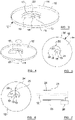
- the disc 12 includes a central mounting aperture 13, which is aligned with the centre of the disc 12, and preferably passes throughout the entire thickness of the disc 12.
- the mounting aperture 13 is generally circular in cross-section, although the mounting aperture can take any suitable shape.
- the disc has top and bottom surfaces 14, 15, which are substantially flat and parallel with one another, and a circumferential side wall 16.
- a calibration aperture 17 is formed through the disc 12.
- the calibration aperture 17 is formed through the entire thickness of the disc 12, and the inner edges of the calibration aperture 17 are (in this example) generally straight, i.e. passing directly from the top surface 14 to the bottom surface 15 in a direction which is perpendicular with the plane of the disc 12.
- the calibration aperture 17 includes an inner edge 18, which is concentric or substantially concentric with the centre of the disc 12.
- the inner edge 18 extends for approximately 180° around the centre of the disc 12, at a distance which is, in the depicted embodiment, about one tenth of the way from the centre of the disc 12 to the outer edge thereof.
- the calibration aperture 17 it is preferable for the calibration aperture 17 to extend at least 180° around the disc 12, although the invention is not limited to this.
- a spacing edge 19 extends from one end of the inner edge 18.
- the spacing edge 19 is straight, and extends directly or substantially directly radially outwardly from the centre of the disc 12 towards the outer edge thereof.
- the length of the spacing edge 19 is, in the example shown, around one third of the total radius of the disc 12.
- the calibration aperture 17 has an outer edge 20, which is curved and extends from the other end 21 of the inner edge 18 to the outer end 22 of the spacing edge 19.
- the outer edge 20 of the calibration aperture 17 is shaped as follows. Where the outer edge 20 meets the inner edge 18, these edges 18, 20 converge at a point, and at this point the effective distance between the inner and outer edges 18, 20 is zero.
- the radial distance between the inner and outer edges 18, 20 increases linearly (i.e. by the same amount for each unit of angular distance) until the outer edge 20 meets the outer point of the spacing wall 19, at which point the radial distance between the inner and outer edges 18, 20 is identical to the length of the spacing wall 19.
- Figure 4 shows the disc 12 mounted for rotation around an axis 23, which passes through the mounting aperture 13, and is perpendicular to the plane of the disc 12.
- an arrow represents the fact that, in use, the disc 12 will rotate around the axis 23.
- the disc 12 may be mounted for rotation around the axis 23, with a plurality of light sources 24 being positioned on one side of the disc 12, and an elongate light receiving array 25 being positioned on the other side of the disc 12.
- the plurality of light sources 24 are arranged so that, looking at the disc 12 along the axis of rotation 23, the light sources 24 are arranged in a line which is radial with respect to the disc 12.
- the line of light sources 24 extends from a point between the mounting aperture 13 of the disc 12 and the inner edge 18 of the calibration aperture 17, outwardly to a position which is further from the mounting aperture 13 than the furthest end of the spacing edge 19.
- the light sources 24 are, therefore, when viewed along the axis of rotation 23, arranged in a line which extends radially on one side of the centre of the disc 12.
- the elongate light receiving array 25 is arranged to be directly or substantially directly opposite the light sources 24.
- the disc 12 is preferably comprised of a material that is opaque to the radiation emitted by the light sources 24.
- the disc 12 is rotated to a position in which any part of the calibration aperture 17 is aligned between the light sources 24 and the light receiving array 25, light from one or more of the light sources 24 may pass through the calibration aperture 17 and be received by the light receiving array 25. If, on the other hand, the disc 12 is rotated to a position where no part of the calibration aperture 17 is aligned between the light sources 24 and the light receiving array 25, then the light from the sources 24 will be blocked from reaching the light receiving array 25.
- the light sources 24 and light receiving array 25 remain stationary, while the disc 12 rotates around the axis 23.
- the light sources 24 and light receiving array 25 are connected to a processor 26, which sends control signals to the light sources 24, and receives signals from the light receiving array 25.
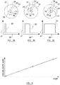
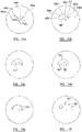
- Figures 8a, 8b, and 8c show the disc 12 in three different rotational orientations with respect to the light sources 24 and light receiving array 25.
- a graph showing schematically the light intensity 27 received by the light receiving array 25, as a function of distance 28 along its length, passing from the inner end thereof to the outer end.
- Figure 8a shows a rotational position in which a relatively narrow part of the calibration aperture 17 overlaps with the light sources 24 and light receiving array 25. It can be seen that the intensity profile for this position comprises a relatively narrow peak 29.
- Figure 8b shows a position when the disc 12 has rotated (in this example, clockwise) with respect to the position shown in 8a, so that the light sources 24 and light receiving array 25 overlap with a wider part of the calibration aperture 17, near the middle thereof. It can be seen that the intensity profile for this position comprises a wider peak 30.
- figure 8c shows the position where the disc 12 has rotated so that the light sources 24 and light receiving array 25 overlap with a wide part of the calibration aperture 24, close to the spacing edge 19.
- the intensity profile for this position comprises a peak 31 that is wider than the peaks 29, 30 that appear for the other rotational positions.
- the inner edge 18 of the calibration aperture 17 is effectively radially stationary with respect to the light sources 24 and light receiving array 25.
- the outer edge 20 of the calibration aperture appears to move steadily from an initial position that is close to the inner edge 18 (as shown in figure 8a ), away from the inner edge 18 until it is at a maximum distance therefrom, near the spacing aperture 19 (as shown in figure 8c ).
- Figure 9 schematically shows how the width of the intensity profile increases linearly as the angle of the disc 12 changes. It will be understood that the graph shown in figure 9 covers the portion of rotation of the disc 12 in which at least some part of the calibration aperture 17 overlaps with the light sources 24 and light receiving array 25. At angular positions where no part of the calibration apertures 17 overlaps in this way, then zero or substantially zero light from the light sources 24 will be detected by the light receiving array 25.
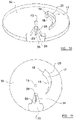
- Figures 10 and 11 show a further disc 32 which includes a calibration aperture 17 including an inner wall 18, outer wall 20 and a spacing wall 19 as described above.
- the further disc 32 has a central mounting aperture 13, on which the disc 32 may be mounted for rotation about an axis.
- the further disc 32 also includes a holding aperture 33, for releasably retaining a cuvette or other device which holds a sample of fluid to be analysed.
- the overall shape of the holding aperture 33 will depend upon the shape of the cuvette other device which is to be used with the disc 32, and it is expected that the shape of the holding aperture 33 will generally match the exterior shape of the cuvette or other device.
- the holding aperture 33 is formed at the edge of the disc 32, and extends generally inwards towards (but does not reach) the central mounting aperture 13.
- the location 34 where a sample chamber of the cuvette will be located.
- the sample chamber will be arranged generally radially with respect to the disc 32, and extends between an inner end 35, which is set a radius r 1 from the centre of the disc 32, and an outer end 36, which is set at a distance r 2 from the centre of the disc 32.
- the calibration aperture 17 is formed in the disc 32 such that the inner edge 18 thereof, is at a distance which is equal to, or less than, r 1 from the centre of the disc 32. At the widest point of the calibration aperture 17, the outer edge 20 lies at a distance which is substantially equal to, or greater than, r 2 from the centre of the disc 32.
- the length of the spacing wall 19 is roughly equal to the length the sample chamber.
- blood is the fluid to be analysed.
- a sample of blood is loaded into a cuvette in known fashion.
- the cuvette is then fixed in place in the holding aperture 33, so that its sample chamber lies in the position 34 indicated in figures 10 and 11 .
- the disc 32 is then rotated about its axis. Any suitable rotation rate may be used, although one example of a suitable rate is 6,000rpm.
- a calibration stage of the apparatus is then carried out.
- an array of light sources is arranged to be on one side of the disc 32, and an array of light sensors is placed in a corresponding location on the opposite side of the disc 32.
- one of the light sources in the array is illuminated. This may be, for example, the innermost light source in the array. While this first light source is illuminated, the signals from the light sensors are analysed at several different rotational positions in which the calibration aperture 17 is aligned between the light sensors and the light sources. For instance, a reading may be taken when the narrowest part of the calibration aperture 17 is aligned between the light sources and the light sensors. Ten or twenty (for example) readings may then be taken at spaced-apart angular positions, culminating in a final reading when the widest part of the calibration aperture 17 is aligned between the light sources and the light sensors.
- the signals gathered from the light sensors at each of these rotational positions are stored, to generate an intensity profile for the light source that is illuminated.
- an intensity profile for the light source that is illuminated.
- repeated intensity profiles may be taken during different rotations of the disc 32. For instance, ten readings may be taken.
- the first light source is extinguished and a second light source is illuminated.
- This process is repeated, with each of the light sources being illuminated in turn.
- a convenient way of carrying this step out may be to illuminate each light source in turn beginning at the innermost light source and working towards the outermost light source, or vice versa.
- the light sources can be illuminated in any sequence.
- a first one of the light sources is illuminated, with the other light sources being extinguished.
- the signals from the light sensors are gathered as the analysis chamber is aligned between the light sources and the light sensors. This may be repeated, for instance, ten times.
- the first light source is extinguished and a second light source is illuminated, and this measurement process is repeated.
- each of the light sources is illuminated in turn, and the signals gathered by the light sensors are received when the analysis chamber is positioned between the light sources and the light sensors.
- the blood in the sample chamber will separate into two main phases, namely a relatively opaque phase comprising the blood red cells, and a relatively transmissive phase comprising the other components of the blood, such as serum. Between these two phases there will be an "edge". Effectively, the red blood cells of the blood sample will cast a shadow on the light sensing array, with the edge of this shadow being an indicator of the position where the red blood cells in the blood sample terminate.
- the calibration stage information is gathered regarding the position in which the edge of the shadow falls when the outer edge 20 of the calibration aperture 17 is positioned at various radial distances from the centre of the disc 32, i.e. various distances along the length of the light sensing array.
- the distance of the outer edge 20 of the calibration aperture 17 from the centre of the disc 32 is known - the rotational position of the disc 32 at each calibration point is known, and the shape of the outer edge 20 of the calibration aperture 17 is also known.
- the outer edge 20 of the calibration aperture 17 in this example is continuously curved, and so does not have clearly demarked edge regions at different distances from the centre of the disc 32.
- calibration readings are taken at set angular positions of the disc 32, where these angular positions are spaced apart from each other.
- this intensity profile can then be compared to the intensity profiles that were gathered during the calibration stage.
- the intensity profile arising from the blood sample will include edges, indicating the position where the red cells start and terminate and the serum terminates. These edges can be compared to the edge that appears in the data from each of the calibration stages. Where the position of the edge in the intensity profile arising from the blood sample is the same as the position of the edge in an intensity profile from the calibration stage, it can be concluded that the position of the point where the red blood cells of the blood sample end, as a function of distance from the centre of the disc 32, is the same as the position of the outer edge 20 of the calibration aperture 17, in the rotational position corresponding to that calibration stage, again as a function of distance from the centre of disc 32. The same is true of the start of the red blood cells and the serum/air boundary.
- an interpolation process can be used to determine the position of the termination of the red blood cells in the blood sample, compared to the positions of the edges in the two calibration stages. For instance, if the edge arising from the blood sample falls halfway between the edges in the two calibration stages, it may be concluded that the position of the termination of the red cells lies halfway between the positions of the outer edge 20 of the calibration aperture 17 in the two appropriate calibration steps.
- this method eliminates many possible sources of error that might arise from mis-calibration. Because the cuvette is held rigidly in place with respect to the calibration aperture, the spatial relation between the cuvette and the calibration aperture is fixed. This means that any errors arising from misalignment of the disc 32 itself, the light sources and/or the light sensors will be compensated for - the calibration stage will correctly register the position of the outer edge of the calibration aperture at various rotational positions, and this data can then be applied to the signal derived during analysis of the blood sample. Any errors or variation in the relative positions of various components will therefore automatically be corrected for.
- the disc 32 may have timing features thereon to assist the apparatus in determining the angular position of the disc 32 during rotation.
- the disc 32 may have three evenly angularly-spaced notches formed therethrough, with these notches being provided at known angular locations with respect both to the holding aperture 33 and the calibration aperture 17.
- the light sensing array will receive three "flashes" of light at evenly-spaced time intervals, and the system will then be able to determine the rotational orientation of the disc 32.
- the use of features of this kind to determine the rotational orientation of a disc during centrifugation is known per se and will not be discussed in detail here.
- Figures 12a and 12b show different cross-sectional shapes for the outer edge 20 of the calibration aperture 17.
- Figure 12a shows the calibration aperture 17 as discussed above, in which the outer edge 20 thereof is straight in cross-section, passing directly from the top surface to the bottom surface of the disc, and being aligned perpendicular or substantially perpendicular to the plane of the disc.
- the outer edge 20 has a cross-sectional shape having an upper wall 37 which slopes, as it passes from the top surface 14 towards the bottom surface 15, in a direction which is towards the centre of the disc 32.
- the upper wall 37 terminates slightly above the midpoint of the thickness of the disc 32.
- a middle wall 38 is preferably relatively short and protrudes directly from the end of the upper wall 37 towards the bottom surface 15 of the disc 32, in a direction which is perpendicular or substantially perpendicular to the plane of the disc 32.
- middle wall 38 Extending from the lower end of middle wall 38 is a lower wall 39. As the lower wall 39 passes from the middle wall 38 to the bottom surface 15 of the disc 32, the lower wall 39 slopes in a direction away from the centre of the disc 32.
- the cross-sectional profile of the outer wall 20 in this embodiment is symmetrical or substantially symmetrical around a plane which lies halfway through the thickness of the disc 32.
- the sample chamber of the cuvette that holds the sample under analysis, is set to be at the same position with respect to the depth of the disc as the middle wall 38. This ensures that the shadow cast by the middle wall 38 on the light sensing array can be compared accurately to the shadow that is cast by the fluid sample held within the sample chamber.
- the thickness of the middle wall 38, in the depth direction of the disc 32 may also be the same, or substantially the same, as the thickness of a blood sample held within the sample chamber. This will mean that the shadow cast by the middle wall 38 will be as directly comparable as possible to the shadow cast by fluid in the sample chamber.
- Figures 13a-13f show potential cross-sectional shapes for the outer edge 20 of the calibration aperture 17.
- Figure 13a shows a straight cross-sectional shape with squared edges, corresponding to the shape shown in figures 3-6 , 10 , 11 and 12a .
- Figure 13b shows a shape which is similar to that shown in 13a, although where the outer edge 20 meets the upper and lower surfaces 14, 15 of the disc 32 there are rounded or radiused edges 40.
- Figure 13c shows further alternative in which the profile of the outer edge 20 is rounded and approximately semi-circular.
- Figure 13d shows the profile shown in figure 12b , involving upper and lower walls 37, 39, with a middle wall 38 therebetween.
- Figure 13e shows a further alternative, similar to that shown in figure 13d , although the upper and lower walls 41, 42 are not separated by a middle wall, and converge at a sharp point 43
- figure 13f shows a further alternative in which the profile of the outer edge 20 is curved in a parabolic manner, thereby presenting a more pointed edge than the example shown in figure 13c .
- Figures 14a-14f show different calibration apertures that are suitable for use with the present invention.
- a disc which, instead of having a single calibration aperture, has four separate calibration apertures 44a-44d.
- Each of the calibration apertures 44a-44d has an inner edge 45 which lies at the same distance from the centre of the disc.
- Each of the calibration apertures 44a-44d is generally rectangular and elongate, extending radially directly away from the centre of the disc.
- a first one 44a of the calibration apertures is relatively short, terminating at a first distance from the centre of the disc.
- a second one 44b of the calibration apertures is longer, terminating at a greater distance from the centre of the disc.
- a third one 44c of the calibration apertures is longer still, terminated at a third distance from the centre of the disc, which is greater than the second distance.
- a fourth one 44d of the apertures is longest, terminating a fourth distance from the centre of the disc, which is greater than the other three distances.
- the inner edges 45 of the calibration apertures 44a-44d will lie at a distance which is the same as, or slightly less than, the distance of the inner end of the sample chamber from the centre of the disc.
- the outer end of the fourth calibration aperture 44d in the centre of the disc will be at approximately the same, or slightly more than, the distance at which the outer end of the sample chamber lies from the centre of the disc.
- each of the apertures 44a-44d will function in a similar way to the single calibration aperture 17 discussed above.
- the outer ends of each of the apertures 44a-44d will cast respective shadows on the array of light sensors at different positions, thus allowing calibration of the system which can subsequently be used in analysing a blood sample, or sample of other liquid held in the sample chamber.
- Figure 14b shows an alternative shape for a single calibration aperture 46, having an outer edge 47 which has several (in this example, six) connected calibration edges 48a-48f, each of which is concentric with the centre of the disc.
- the calibration edges 48a-48f are connected by radially-extending connecting edges.
- the calibration edges 48a-48f are preferably set at steadily-increasing radial distances from the centre of the disc.
- this calibration aperture 46 works in a similar manner to the calibration aperture 17 shown in figure 3 .
- a difference is that, as the disc rotates, each of the calibration edges 48a-48f will cast, for a length of time, a shadow which remains stationary, thus allowing a more robust and accurate and determination of where the shadow falls on the light sensing array, relating to each the calibration edges 48a-48f.
- This example therefore has clearly demarked edge regions or portions 48a-48f, set at different linear distances from the centre of the disc.
- Figure 14c shows a calibration aperture 17 as shown in figure 3 and elsewhere.
- Figure 14d shows an alternative aperture 49, which is similar in shape to the calibration aperture 17 shown in figure 3 , although in this case the inner edge 50 of the calibration aperture 49 is not concentric with the centre of the disc.
- This aperture 49 therefore has both an inner edge 50 and an outer edge 53 that continuously vary in distance from the centre of the disc.
- This aperture 49 could therefore be used to obtain calibration information based on the outer edge and, separately, on the inner edge. This is explained in more detail below.
- Figure 14e shows an alternative set of calibration apertures 51, each of which comprises a circular or substantially circular aperture formed through the depth of the disc.
- the apertures 51 are evenly radially spaced around the centre of the disc.
- a first one of the apertures 51 is provided at a first distance from the centre of the disc.
- Each successive aperture is provided at a distance which is incrementally greater than the previous one, cumulating in a final aperture 51 which is at a greatest distance from the centre of the disc.
- apertures 51 function in a similar manner in the apertures 44a-44d shown in figure 14a .
- the outer edge of each of the apertures 51 is at a known location, and casts a shadow on the light-sensing array as the aperture 51 passes between the light sources and the light sensing array.
- figure 14f shows a further set of calibration apertures 52, which are again circular or substantially circular apertures which are formed through the depth of the disc.
- the apertures are evenly radially spaced around the centre of the disc. The centres of the apertures are all located at the same or substantially the same radial distance from the centre of the disc. However, the radii of the apertures increase steadily from a first aperture 52, which has the smallest radius, to a final one of the apertures 52, which has the greatest radius. It will be understood that the outer edge of each aperture 52 will be located at an increasing distance from the centre of the disc, and each edge will therefore cast a shadow on the light sensitive array in a different position, corresponding to a known outer edge position.
- calibration aperture(s) there are many different shapes for calibration aperture(s) that can be used with the present invention. What is important is that the calibration aperture(s) provide an outer edge or series of outer edges which, as the disc rotates, are at different known distances from the centre of the disc.
- the calibration aperture(s) will ideally present a range of outer edges, or a single shaped outer edge, which are at, or have parts thereof at, different radial distances from the centre of the disc, extending between a relatively short distance, being equal to or less than the radial distance at which the inner edge of the sample chamber will lie in use (or, alternatively, equal to or less than the smallest distance from the centre of the disc at which an edge to be observed can be expected to lie), and a greatest distance, corresponding to a position which is equal to or greater than the position where the outer end of the sample chamber will lie during use (or, alternatively, equal to or more than the greatest distance from the centre of the disc at which an edge to be observed can be expected to lie).
- the invention may be used to determine the volume occupied by the lightest or least dense fraction in a multi-phase liquid.
- one or more calibration apertures could be provided in which the distance of the inner edge of each aperture varies from the centre of the disc varies, and the shadow cast on the light sensing array by the inner edge or edges is analysed to provide calibration for later analysis of a fluid sample.
- the outer edge of the or each calibration aperture may be radially stationary with respect to the centre of the disc.
- an intermediate fractional component of the fluid under analysis i.e. a component which is neither the most dense nor the least dense.
- the edge that appears at the inner limit of this fractional component and the edge that appears at the outer limit of the fractional component may need to be determined.
- two separate calibration apertures may be provided through the disc, one of which has a stationary inner edge and an outer edge whose distance from the centre of the disc varies (as shown in figure 3 ), and a second calibration aperture which has a stationary outer edge, and an inner edge whose distance varies from the centre of the disc.
- two separate calibration stages may be carried out, one to detect the shadows cast by the outer edge of the first calibration aperture, and a second one to detect shadows cast by the inner edge of the second calibration aperture.
- two separate analysis stages may take place, one to measure the inner edge cast by the fractional component of the liquid under analysis and a second, separate analysis stage to detect the position of the shadow cast by the outer edge of the component or fraction under analysis.
- both the inner and outer edges may be detected in a single calibration stage and/or the inner and outer edges of the fractional component under analysis may be detected in a single measurement stage.
- a set of calibration apertures may be provided for either or both of the inner or outer edges.
- both the inner edge 50 and the outer edge 53 of the same aperture 49 may be used for calibration purposes.
- Embodiments of the invention may, at a minimum, use only one single aperture to obtain calibration information for both inner and outer edges. The skilled reader will understand how this may be applied to the other types of aperture disclosed herein.
- the linear distances of the inner edges 45 of the respective apertures may vary from the centre of the disc, as well as (as is the case in figure 14a ) the linear distances of the outer edges 44a-44d of the apertures from the centre of the disc varying.
- the calibration stage is carried out and completed before the measurement of a blood sample takes place.
- the skilled reader will appreciate that there is no reason for these steps to occur in this order. What is important is that, for each of the light sources in the array, the light source is illuminated and an intensity profile for the calibration aperture(s), and for the fluid sample, is gathered.
- the intensity profile from the fluid sample may equally be gathered before the intensity profiles from the calibration aperture(s) are obtained.
- each of the light sources is illuminated, and while the light source is illuminated intensity profiles are gathered both from the calibration aperture(s) and from the fluid sample. This allows measurements to be made for calibration purposes, and measurements of the fluid sample to be made, in an efficient manner.
- the element which has the calibration aperture(s) formed therethrough, and which holds the fluid sample is referred to as a disc.
- this element which has the calibration aperture(s) formed therethrough, and which holds the fluid sample, is referred to as a disc.
- the outer edge of this element needs to be circular and this element can take any suitable shape.
- each calibration aperture may comprise a region of the disc which is transparent or substantially transparent to the radiation. This may comprise, for example, an insert of a transparent material which is placed into a hole in the disc. It should therefore be understood that the term "calibration aperture" requires a region of the disc through which the radiation can pass unimpeded or substantially unimpeded, and that this does not necessarily require a physical hole passing through the disc.
- the light sensing array is positioned on the opposite side of the disc from the light sources.
- the information gathered by the light sensing array therefore provides an indication of the transmission of light from the light sources through the fluid in the sample chamber. It is also envisaged that, in arrangements not embodying the present invention, this technique could be used with the measurement of reflectivity, i.e. the light sensing array is placed on the same side of the disc as the light sources, and the light gathered by the light sensing array is indicative of the light reflected by the sample in the sample chamber.
- one or more reflective elements such as mirrors may be placed on, or incorporated into, the surface of the disc that faces the light sources and the light sensing array.
- the light reflecting element(s) may be shaped in the same way as the calibration apertures discussed above.
- the light reflecting elements may also be incorporated into the disc so that the reflecting surface(s) thereof lie at the same depth as a fluid sample held by a cuvette or other sample container which is to be used with the disc.
- light will be reflected from the reflective element(s), and an illumination profile or reflection profile can then be gathered for each light source at various positions of the outer edge of the reflective element(s).
Landscapes
- Health & Medical Sciences (AREA)
- Life Sciences & Earth Sciences (AREA)
- Chemical & Material Sciences (AREA)
- Physics & Mathematics (AREA)
- Engineering & Computer Science (AREA)
- General Health & Medical Sciences (AREA)
- Hematology (AREA)
- Biomedical Technology (AREA)
- Analytical Chemistry (AREA)
- Immunology (AREA)
- General Physics & Mathematics (AREA)
- Pathology (AREA)
- Biochemistry (AREA)
- Dispersion Chemistry (AREA)
- Molecular Biology (AREA)
- Heart & Thoracic Surgery (AREA)
- Chemical Kinetics & Catalysis (AREA)
- Vascular Medicine (AREA)
- Medicinal Chemistry (AREA)
- Biophysics (AREA)
- Urology & Nephrology (AREA)
- Food Science & Technology (AREA)
- Ecology (AREA)
- Animal Behavior & Ethology (AREA)
- Thermal Sciences (AREA)
- Clinical Laboratory Science (AREA)
- Anesthesiology (AREA)
- Cardiology (AREA)
- Public Health (AREA)
- Veterinary Medicine (AREA)
- Automatic Analysis And Handling Materials Therefor (AREA)
- Investigating Or Analysing Biological Materials (AREA)
- Centrifugal Separators (AREA)
- Sampling And Sample Adjustment (AREA)
- Investigating Or Analysing Materials By Optical Means (AREA)
- Optical Measuring Cells (AREA)
Claims (15)
- Probenhalter (12, 32) zur Verwendung in einer Zentrifuge, wobei der Probenhalter (12, 32) im Allgemeinen planar ist und umfasst:eine Öffnung oder Aussparung (33) zum lösbaren Halten eines Probenspeicherelements, das eine Probenkammer beinhaltet, die dafür ausgelegt ist, ein Flüssigkeitsvolumen aufzunehmen;einen Mittelpunkt (13), um den sich der Halter (12, 32) während der Verwendung dreht; undein oder mehrere Kalibrierungsmerkmale (17, 45, 46, 51, 52), wobei das/die Kalibrierungsmerkmal(e) (17, 45, 46, 51, 52) eine oder mehrere Außenkanten (20, 44a-d, 48a-f, 53) umfassen, die auf der Seite des oder jedes Kalibrierungsmerkmals (17, 45, 46, 51, 52) liegen, die am weitesten von dem Mittelpunkt (13) entfernt ist, und die eine oder mehreren Außenkanten (20, 44a-d, 48a-f, 53) eine Reihe von radial beabstandeten Außenkantenabschnitten oder -positionen umfassen, die in unterschiedlichen Abständen von dem Mittelpunkt (13) als Funktion der Winkelposition um den Mittelpunkt (13) beabstandet sind, und wobei das oder jedes Kalibrierungsmerkmal (17, 45, 46, 51, 52) eine durch die gesamte Dicke des Halters (12, 32) gebildete Öffnung ist oder ein Einsatz aus einem transparenten oder im Wesentlichen transparenten Material ist, der in ein Loch in dem Halter (12, 32) platziert wird.
- Probenhalter (12, 32) nach Anspruch 1, umfassend ein Kalibrierungsmerkmal (17, 46) mit einer durchgehenden Außenkante (20, 481-f, 53), die eine Vielzahl von Außenkantenabschnitten oder -positionen aufweist, die sich in variierenden Abständen von dem Mittelpunkt (13) befinden.
- Probenhalter (12, 32) nach Anspruch 2, wobei die Außenkante (20, 53) des Kalibrierungsmerkmals (17) gekrümmt ist und der Abstand der Außenkante (20, 53) von dem Mittelpunkt (13) entlang seiner Länge kontinuierlich oder im Wesentlichen kontinuierlich variiert, oder wobei die Außenkante (48a-f) des Kalibrierungsmerkmals (46) eine Reihe von diskreten Außenkantenabschnitten (481-f) umfasst, von denen sich jeder in einem unterschiedlichen Abstand von dem Mittelpunkt (13) befindet.
- Probenhalter nach Anspruch 1, umfassend eine Reihe von einzelnen, beabstandeten Kalibrierungsmerkmalen (45, 51, 52), wobei jedes Merkmal (45, 51, 52) eine Außenkante (44a-d) aufweist, die sich in einem unterschiedlichen Abstand von dem Mittelpunkt (13) befindet.
- Probenhalter nach Anspruch 4, wobei jedes Kalibrierungsmerkmal (45) im Wesentlichen länglich und so angeordnet ist, dass es sich in einer im Wesentlichen radialen Richtung in Bezug auf den Mittelpunkt (13) erstreckt, oder wobei jedes Kalibrierungsmerkmal (51, 52) im Wesentlichen kreisförmig ist.
- Probenhalter nach einem vorhergehenden Anspruch, wobei die Kalibrierungsmerkmale ferner eine oder mehrere Innenkanten umfassen, die auf der Seite des oder jedes Kalibrierungsmerkmals liegen, die dem Mittelpunkt am nächsten ist, und die eine oder mehreren Innenkanten eine Reihe von radial beabstandeten Innenkantenabschnitten oder -positionen umfassen, die in unterschiedlichen Abständen von dem Mittelpunkt als Funktion der Winkelposition um den Mittelpunkt beabstandet sind.
- Probenhalter (12, 32) nach einem vorhergehenden Anspruch in Kombination mit einem Probenaufnahmeelement, das dafür ausgelegt ist, in der Öffnung oder Aussparung (33) des Probenhalters (12, 32) aufnehmend gehalten werden kann, wobei das Probenaufnahmeelement eine Probenkammer beinhaltet, in der, während der Verwendung, ein zu analysierendes Fluid aufgenommen sein kann.
- Probenhalter (12, 32) und Probenaufnahmeelement nach Anspruch 7, wobei die Probenkammer eine Länge aufweist, die, bei Verwendung, so angeordnet ist, dass sie in einer im Wesentlichen radialen Richtung in Bezug auf den Mittelpunkt (13) liegt, und wobei die Außenrandabschnitte oder -positionen des Kalibrierungsmerkmals/der Kalibrierungsmerkmale (17, 45, 46, 51, 52) Abständen von dem Mittelpunkt (13) entsprechen, die entlang der Länge der Probenkammer liegen.
- Zentrifugenvorrichtung, umfassend:einen Probenhalter (12, 32) und ein Probenaufnahmeelement nach Anspruch 7 oder 8;eine Rotationsanordnung, die dafür ausgelegt ist, den Probenhalter (12, 32) zu halten und den Probenhalter (12, 32) um den Mittelpunkt (13) davon zu drehen;eine Strahlungsquelle, die so angeordnet ist, dass sie sich auf einer Seite des Probenhalters (12, 32) befindet; undeinen Strahlungsdetektor, der dafür ausgelegt ist, die von der Strahlungsquelle emittierte Strahlung zu detektieren, und auf der der Lichtquelle gegenüberliegenden Seite des Probenhalters (12, 32) oder auf derselben Seite des Halters wie die Strahlungsquelle angeordnet ist.
- Zentrifugenvorrichtung nach Anspruch 9, umfassend eine längliche Anordnung von Strahlungsquellen, die entlang einer Linie angeordnet sind, die im Wesentlichen radial in Bezug auf die Mitte des Probenhalters (12, 32) ist und sich über einen radialen Abstand erstreckt, der der radialen Erstreckung der Probenkammer entspricht oder größer als diese ist, und vorzugsweise auch eine längliche Anordnung von Strahlungsdetektoren umfasst, die in einer Linie angeordnet sind, die im Wesentlichen radial in Bezug auf die Mitte des Probenhalters (12, 32) ist, und über einen Abstand angeordnet sind, der demjenigen der Probenkammer entspricht oder größer als dieser ist.
- Verfahren zur Kalibrierung und Analyse, umfassend die folgenden Schritte:Bereitstellen einer Zentrifugenvorrichtung nach Anspruch 9 oder 10;Bereitstellen einer Fluidprobe in der Probenkammer des Probenaufnahmeelements;Drehen des Probenhalters (12, 32) unter Verwendung der Rotationsanordnung;Beleuchten der Strahlungsquelle und, während der Beleuchtung der Strahlungsquelle, Aufzeichnen eines Intensitätsprofils für jede(n) Außenkantenabschnitt oder -position des Kalibrierungsmerkmals/der Kalibrierungsmerkmale (17, 45, 46, 51, 52), umfassend Signale, die aus dem Strahlungsdetektor empfangen werden, wenn Strahlung aus der Strahlungsquelle durch das/die Kalibrierungsmerkmal(e) (17, 45, 46, 51, 52) übertragen oder von diesem/diesen reflektiert wird;Beleuchten der Strahlungsquelle und, während der Beleuchtung der Strahlungsquelle, Aufzeichnen eines Intensitätsprofils für die Fluidprobe, umfassend Signale, die aus dem Strahlungssensor empfangen werden, wenn Strahlung aus der Strahlungsquelle durch die Fluidprobe übertragen oder von dieser reflektiert wird; undBestimmen der Position mindestens einer Grenze zwischen Phasen in der Fluidprobe, basierend auf der Korrelation zwischen einem Merkmal in dem Intensitätsprofil der Fluidprobe, das der Grenze entspricht, und Merkmalen in den Intensitätsprofilen, die sich auf eine(n) oder mehrere der Außenrandabschnitte oder -positionen des Kalibrierungsmerkmals/der Kalibrierungsmerkmale (17, 45, 46, 51, 52) beziehen.
- Verfahren nach Anspruch 11, wobei eine Vielzahl von Strahlungsquellen bereitgestellt ist und die Aufzeichnung eines Intensitätsprofils für jede(n) oder eine Auswahl der Außenrandabschnitte oder -positionen des Kalibrierungsmerkmals/der Kalibrierungsmerkmale (17, 45, 46, 51, 52) und die Aufzeichnung eines Intensitätsprofils für die Fluidprobe für jede der beleuchteten Strahlungsquellen reihum durchgeführt wird.
- Verfahren nach Anspruch 11 oder 12, wenn von Anspruch 10 abhängig, wobei das Verfahren ferner die folgenden Schritte umfasst:während der Beleuchtung der Strahlungsquelle, Aufzeichnen eines Intensitätsprofils für jede(n) Innenkantenabschnitt oder -position des Kalibrierungsmerkmals/der Kalibrierungsmerkmale (17, 45, 46, 51, 52), umfassend Signale, die aus dem Strahlungsdetektor empfangen werden, wenn Strahlung aus der Strahlungsquelle durch das/die Kalibrierungsmerkmal(e) (17, 45, 46, 51, 52) übertragen oder von diesem/diesen reflektiert wird; undBestimmen der Position mindestens einer Grenze zwischen Phasen in der Fluidprobe, basierend auf der Korrelation zwischen einem Merkmal in dem Intensitätsprofil der Fluidprobe, das der Grenze entspricht, und Merkmalen in den Intensitätsprofilen, die sich auf eine(n) oder mehrere der Innenkantenabschnitte oder -positionen des Kalibrierungsmerkmals/der Kalibrierungsmerkmale (17, 45, 46, 51, 52) beziehen.
- Probenhalter zur Verwendung in einer Zentrifuge, wobei der Probenhalter im Allgemeinen planar ist und Folgendes umfasst:eine Öffnung oder Aussparung (33) zum lösbaren Halten eines Probenspeicherelements, das eine Probenkammer beinhaltet, die dafür ausgelegt ist, ein Flüssigkeitsvolumen aufzunehmen;einen Mittelpunkt (13), um den sich der Halter während der Verwendung dreht; undein oder mehrere Kalibrierungsmerkmale (51, 52), wobei das/die Kalibrierungsmerkmal(e) (51, 52) eine oder mehrere Innenkanten umfassen, die auf der Seite auf dem oder jedem Kalibrierungsmerkmal liegen, die dem Mittelpunkt (13) am nächsten ist, und die eine oder mehreren Innenkanten eine Reihe von radial beabstandeten Kantenabschnitten oder -positionen aufweisen, die in unterschiedlichen Abständen von dem Mittelpunkt (13) beabstandet sind, und wobei das oder jedes Kalibrierungsmerkmal (51, 52) eine Öffnung ist, die durch die gesamte Dicke des Halters gebildet ist, oder ein Einsatz aus einem transparenten oder im Wesentlichen transparenten Material ist, der in ein Loch in dem Halter platziert wird.
- Probenhalter zur Verwendung in einer Zentrifuge, wobei der Probenhalter im Allgemeinen planar ist und Folgendes umfasst:eine Öffnung oder Aussparung zum lösbaren Halten eines Probenspeicherelements, das eine Probenkammer beinhaltet, die dafür ausgelegt ist, ein Flüssigkeitsvolumen aufzunehmen;einen Mittelpunkt, um den sich der Halter während der Verwendung dreht;ein oder mehrere erste Kalibrierungsmerkmale, wobei das/die erste(n) Kalibrierungsmerkmal(e) eine oder mehrere Außenkanten umfassen, die auf der Seite des oder jedes ersten Kalibrierungsmerkmals liegen, die am weitesten von dem Mittelpunkt entfernt ist, und die eine oder mehreren Außenkanten eine Reihe von radial beabstandeten Außenkantenabschnitten oder -positionen umfassen, die in unterschiedlichen Abständen von dem Mittelpunkt beabstandet sind; undein oder mehrere zweite Kalibrierungsmerkmal(e), wobei das/die zweite(n) Kalibrierungsmerkmal(e) eine oder mehrere Innenkanten umfassen, die auf der Seite auf dem oder jedem zweiten Kalibrierungsmerkmal liegen, die dem Mittelpunkt am nächsten ist, und die eine oder mehreren Innenkanten eine Reihe von radial beabstandeten Kantenabschnitten oder -positionen aufweisen, die in unterschiedlichen Abständen von dem Mittelpunkt beabstandet sind,wobei das oder jedes erste oder zweite Kalibrierungsmerkmal eine Öffnung ist, die durch die gesamte Dicke des Halters gebildet ist, oder ein Einsatz aus einem transparenten oder im Wesentlichen transparenten Material ist, der in ein Loch in dem Halter platziert wird.
Applications Claiming Priority (2)
| Application Number | Priority Date | Filing Date | Title |
|---|---|---|---|
| GB1617939.2A GB2555402B (en) | 2016-10-24 | 2016-10-24 | A system and method for fluid analysis |
| PCT/GB2017/053055 WO2018078325A1 (en) | 2016-10-24 | 2017-10-10 | A system and method for calibrating a centrifuge |
Publications (3)
| Publication Number | Publication Date |
|---|---|
| EP3529613A1 EP3529613A1 (de) | 2019-08-28 |
| EP3529613B1 true EP3529613B1 (de) | 2022-08-03 |
| EP3529613B8 EP3529613B8 (de) | 2022-09-07 |
Family
ID=57738073
Family Applications (1)
| Application Number | Title | Priority Date | Filing Date |
|---|---|---|---|
| EP17787540.8A Active EP3529613B8 (de) | 2016-10-24 | 2017-10-10 | System und verfahren zur kalibrierung einer zentrifuge |
Country Status (9)
| Country | Link |
|---|---|
| US (1) | US11957827B2 (de) |
| EP (1) | EP3529613B8 (de) |
| JP (1) | JP7050798B2 (de) |
| AU (1) | AU2017349443A1 (de) |
| CA (1) | CA3041182A1 (de) |
| ES (1) | ES2929757T3 (de) |
| GB (1) | GB2555402B (de) |
| MX (1) | MX2019004668A (de) |
| WO (1) | WO2018078325A1 (de) |
Families Citing this family (3)
| Publication number | Priority date | Publication date | Assignee | Title |
|---|---|---|---|---|
| GB2573126B (en) * | 2018-04-24 | 2022-11-09 | Entia Ltd | A method and apparatus for determining haemoglobin concentration |
| CN110841335A (zh) * | 2019-12-19 | 2020-02-28 | 石家庄禾柏生物技术股份有限公司 | 一种全血分离结构 |
| WO2026022093A1 (en) * | 2024-07-22 | 2026-01-29 | Coriolis Pharma Research GmbH | Method of evaluating geometric properties in measurement cells in an analytical ultracentrifugation apparatus |
Family Cites Families (6)
| Publication number | Priority date | Publication date | Assignee | Title |
|---|---|---|---|---|
| GB9424218D0 (en) * | 1994-11-30 | 1995-01-18 | Zynocyte Ltd | Apparatus for analysing blood and other samples |
| DE19515870C1 (de) * | 1995-04-29 | 1996-08-14 | Fresenius Ag | Vorrichtung zur Trennung von Medien in deren Bestandteile |
| US6002474A (en) * | 1998-03-02 | 1999-12-14 | Becton Dickinson And Company | Method for using blood centrifugation device with movable optical reader |
| EP1242157B1 (de) | 1999-10-29 | 2005-01-12 | Bristol-Myers Squibb Company | Verfahren zur herstelung von lösungen mit blut- oder plasma-komponenten mit erhöhten konzentrationen |
| CN101031364A (zh) * | 2004-09-30 | 2007-09-05 | 爱科来株式会社 | 离心分离装置和具有该离心分离装置的分析装置 |
| MX387805B (es) * | 2014-01-22 | 2025-03-18 | Labrador Diagnostics Llc | Medicion rapida de la tasa de sedimentacion de los componentes sanguineos formados a partir de pequeños volumenes de muestra. |
-
2016
- 2016-10-24 GB GB1617939.2A patent/GB2555402B/en active Active
-
2017
- 2017-10-10 MX MX2019004668A patent/MX2019004668A/es unknown
- 2017-10-10 EP EP17787540.8A patent/EP3529613B8/de active Active
- 2017-10-10 AU AU2017349443A patent/AU2017349443A1/en not_active Abandoned
- 2017-10-10 ES ES17787540T patent/ES2929757T3/es active Active
- 2017-10-10 WO PCT/GB2017/053055 patent/WO2018078325A1/en not_active Ceased
- 2017-10-10 US US16/343,950 patent/US11957827B2/en active Active
- 2017-10-10 JP JP2019542809A patent/JP7050798B2/ja active Active
- 2017-10-10 CA CA3041182A patent/CA3041182A1/en not_active Abandoned
Also Published As
| Publication number | Publication date |
|---|---|
| GB201617939D0 (en) | 2016-12-07 |
| ES2929757T3 (es) | 2022-12-01 |
| CA3041182A1 (en) | 2018-05-03 |
| EP3529613B8 (de) | 2022-09-07 |
| US11957827B2 (en) | 2024-04-16 |
| EP3529613A1 (de) | 2019-08-28 |
| MX2019004668A (es) | 2020-01-23 |
| JP7050798B2 (ja) | 2022-04-08 |
| AU2017349443A1 (en) | 2019-05-30 |
| GB2555402B (en) | 2019-10-23 |
| US20200054819A1 (en) | 2020-02-20 |
| JP2019536058A (ja) | 2019-12-12 |
| WO2018078325A1 (en) | 2018-05-03 |
| GB2555402A (en) | 2018-05-02 |
Similar Documents
| Publication | Publication Date | Title |
|---|---|---|
| EP3529613B1 (de) | System und verfahren zur kalibrierung einer zentrifuge | |
| US4218615A (en) | Incremental digital shaft encoder | |
| KR101963106B1 (ko) | 회전각 검출 장치 | |
| US20170074975A1 (en) | Multi-Target Laser Distance Meter | |
| US7594429B2 (en) | System and method for improved optical measurements during rheometric measurements | |
| US4450529A (en) | Method and apparatus for determining encoder accuracy margin in a wheel balancer | |
| US6723287B1 (en) | Measuring system for automatic chemical analyzer | |
| CN102654384B (zh) | 转台式精密离心机动态半径定位直接测量方法 | |
| Schachman et al. | [1] Ultracentrifugal studies with absorption optics and a split-beam photoelectric scanner | |
| US5698851A (en) | Device and method for precise angular measurement by mapping small rotations into large phase shifts | |
| JPH0263162B2 (de) | ||
| EP2843374A1 (de) | Drehwinkelmessvorrichtung | |
| JP6256152B2 (ja) | X線測定装置 | |
| WO2018107342A1 (zh) | 一种反射式角位移光编码器 | |
| JP6771938B2 (ja) | 測定システムの測定場所の位置を決定する方法 | |
| JP4710347B2 (ja) | 分析装置およびそれに使用する分析ディスク | |
| JPS61262638A (ja) | 屈折率測定用センサ− | |
| KR100654205B1 (ko) | 감도 분포를 측정하는 측정 방법 및 장치 | |
| JP2025153433A (ja) | 超音波風速計、及び風速測定方法 | |
| JPH09113228A (ja) | 膜厚計 | |
| JPS59126976A (ja) | ドツプラ−速度計の校正装置 | |
| Rodyushkin et al. | High-speed measuring-computing system for balancing rotors on a production line | |
| Cölfen et al. | Multifunctional cell for measurements of temperature, distance, and refractive index as for determining optical calibration factors in rotating systems | |
| RU2003123565A (ru) | Двухзондовый способ измерения фазовых сдвигов в балансном кольце | |
| CN114964126A (zh) | 对象物的表面测定装置及测定方法 |
Legal Events
| Date | Code | Title | Description |
|---|---|---|---|
| STAA | Information on the status of an ep patent application or granted ep patent |
Free format text: STATUS: UNKNOWN |
|
| STAA | Information on the status of an ep patent application or granted ep patent |
Free format text: STATUS: THE INTERNATIONAL PUBLICATION HAS BEEN MADE |
|
| PUAI | Public reference made under article 153(3) epc to a published international application that has entered the european phase |
Free format text: ORIGINAL CODE: 0009012 |
|
| STAA | Information on the status of an ep patent application or granted ep patent |
Free format text: STATUS: REQUEST FOR EXAMINATION WAS MADE |
|
| 17P | Request for examination filed |
Effective date: 20190508 |
|
| AK | Designated contracting states |
Kind code of ref document: A1 Designated state(s): AL AT BE BG CH CY CZ DE DK EE ES FI FR GB GR HR HU IE IS IT LI LT LU LV MC MK MT NL NO PL PT RO RS SE SI SK SM TR |
|
| AX | Request for extension of the european patent |
Extension state: BA ME |
|
| DAV | Request for validation of the european patent (deleted) | ||
| DAX | Request for extension of the european patent (deleted) | ||
| GRAJ | Information related to disapproval of communication of intention to grant by the applicant or resumption of examination proceedings by the epo deleted |
Free format text: ORIGINAL CODE: EPIDOSDIGR1 |
|
| STAA | Information on the status of an ep patent application or granted ep patent |
Free format text: STATUS: GRANT OF PATENT IS INTENDED |
|
| GRAP | Despatch of communication of intention to grant a patent |
Free format text: ORIGINAL CODE: EPIDOSNIGR1 |
|
| INTG | Intention to grant announced |
Effective date: 20220215 |
|
| RIN1 | Information on inventor provided before grant (corrected) |
Inventor name: BASEY-FISHER, TOBY Inventor name: CLIVE-SMITH, MILLIE |
|
| GRAS | Grant fee paid |
Free format text: ORIGINAL CODE: EPIDOSNIGR3 |
|
| GRAA | (expected) grant |
Free format text: ORIGINAL CODE: 0009210 |
|
| STAA | Information on the status of an ep patent application or granted ep patent |
Free format text: STATUS: THE PATENT HAS BEEN GRANTED |
|
| AK | Designated contracting states |
Kind code of ref document: B1 Designated state(s): AL AT BE BG CH CY CZ DE DK EE ES FI FR GB GR HR HU IE IS IT LI LT LU LV MC MK MT NL NO PL PT RO RS SE SI SK SM TR |
|
| REG | Reference to a national code |
Ref country code: AT Ref legal event code: REF Ref document number: 1509146 Country of ref document: AT Kind code of ref document: T Effective date: 20220815 Ref country code: CH Ref legal event code: PK Free format text: BERICHTIGUNG B8 Ref country code: CH Ref legal event code: EP |
|
| RBV | Designated contracting states (corrected) |
Designated state(s): AL AT BE BG CH CY CZ DE DK EE ES FI FR GR HR HU IE IS IT LI LT LU LV MC MK MT NL NO PL PT RO RS SE SI SK SM TR |
|
| REG | Reference to a national code |
Ref country code: DE Ref legal event code: R096 Ref document number: 602017060234 Country of ref document: DE |
|
| REG | Reference to a national code |
Ref country code: IE Ref legal event code: FG4D |
|
| REG | Reference to a national code |
Ref country code: SE Ref legal event code: TRGR |
|
| REG | Reference to a national code |
Ref country code: NL Ref legal event code: FP |
|
| REG | Reference to a national code |
Ref country code: LT Ref legal event code: MG9D |
|
| REG | Reference to a national code |
Ref country code: ES Ref legal event code: FG2A Ref document number: 2929757 Country of ref document: ES Kind code of ref document: T3 Effective date: 20221201 |
|
| PG25 | Lapsed in a contracting state [announced via postgrant information from national office to epo] |
Ref country code: RS Free format text: LAPSE BECAUSE OF FAILURE TO SUBMIT A TRANSLATION OF THE DESCRIPTION OR TO PAY THE FEE WITHIN THE PRESCRIBED TIME-LIMIT Effective date: 20220803 Ref country code: PT Free format text: LAPSE BECAUSE OF FAILURE TO SUBMIT A TRANSLATION OF THE DESCRIPTION OR TO PAY THE FEE WITHIN THE PRESCRIBED TIME-LIMIT Effective date: 20221205 Ref country code: NO Free format text: LAPSE BECAUSE OF FAILURE TO SUBMIT A TRANSLATION OF THE DESCRIPTION OR TO PAY THE FEE WITHIN THE PRESCRIBED TIME-LIMIT Effective date: 20221103 Ref country code: LV Free format text: LAPSE BECAUSE OF FAILURE TO SUBMIT A TRANSLATION OF THE DESCRIPTION OR TO PAY THE FEE WITHIN THE PRESCRIBED TIME-LIMIT Effective date: 20220803 Ref country code: LT Free format text: LAPSE BECAUSE OF FAILURE TO SUBMIT A TRANSLATION OF THE DESCRIPTION OR TO PAY THE FEE WITHIN THE PRESCRIBED TIME-LIMIT Effective date: 20220803 Ref country code: FI Free format text: LAPSE BECAUSE OF FAILURE TO SUBMIT A TRANSLATION OF THE DESCRIPTION OR TO PAY THE FEE WITHIN THE PRESCRIBED TIME-LIMIT Effective date: 20220803 |
|
| REG | Reference to a national code |
Ref country code: AT Ref legal event code: MK05 Ref document number: 1509146 Country of ref document: AT Kind code of ref document: T Effective date: 20220803 |
|
| PG25 | Lapsed in a contracting state [announced via postgrant information from national office to epo] |
Ref country code: PL Free format text: LAPSE BECAUSE OF FAILURE TO SUBMIT A TRANSLATION OF THE DESCRIPTION OR TO PAY THE FEE WITHIN THE PRESCRIBED TIME-LIMIT Effective date: 20220803 Ref country code: IS Free format text: LAPSE BECAUSE OF FAILURE TO SUBMIT A TRANSLATION OF THE DESCRIPTION OR TO PAY THE FEE WITHIN THE PRESCRIBED TIME-LIMIT Effective date: 20221203 Ref country code: HR Free format text: LAPSE BECAUSE OF FAILURE TO SUBMIT A TRANSLATION OF THE DESCRIPTION OR TO PAY THE FEE WITHIN THE PRESCRIBED TIME-LIMIT Effective date: 20220803 Ref country code: GR Free format text: LAPSE BECAUSE OF FAILURE TO SUBMIT A TRANSLATION OF THE DESCRIPTION OR TO PAY THE FEE WITHIN THE PRESCRIBED TIME-LIMIT Effective date: 20221104 |
|
| PG25 | Lapsed in a contracting state [announced via postgrant information from national office to epo] |
Ref country code: SM Free format text: LAPSE BECAUSE OF FAILURE TO SUBMIT A TRANSLATION OF THE DESCRIPTION OR TO PAY THE FEE WITHIN THE PRESCRIBED TIME-LIMIT Effective date: 20220803 Ref country code: RO Free format text: LAPSE BECAUSE OF FAILURE TO SUBMIT A TRANSLATION OF THE DESCRIPTION OR TO PAY THE FEE WITHIN THE PRESCRIBED TIME-LIMIT Effective date: 20220803 Ref country code: DK Free format text: LAPSE BECAUSE OF FAILURE TO SUBMIT A TRANSLATION OF THE DESCRIPTION OR TO PAY THE FEE WITHIN THE PRESCRIBED TIME-LIMIT Effective date: 20220803 Ref country code: CZ Free format text: LAPSE BECAUSE OF FAILURE TO SUBMIT A TRANSLATION OF THE DESCRIPTION OR TO PAY THE FEE WITHIN THE PRESCRIBED TIME-LIMIT Effective date: 20220803 Ref country code: AT Free format text: LAPSE BECAUSE OF FAILURE TO SUBMIT A TRANSLATION OF THE DESCRIPTION OR TO PAY THE FEE WITHIN THE PRESCRIBED TIME-LIMIT Effective date: 20220803 |
|
| REG | Reference to a national code |
Ref country code: DE Ref legal event code: R097 Ref document number: 602017060234 Country of ref document: DE |
|
| PG25 | Lapsed in a contracting state [announced via postgrant information from national office to epo] |
Ref country code: SK Free format text: LAPSE BECAUSE OF FAILURE TO SUBMIT A TRANSLATION OF THE DESCRIPTION OR TO PAY THE FEE WITHIN THE PRESCRIBED TIME-LIMIT Effective date: 20220803 Ref country code: MC Free format text: LAPSE BECAUSE OF FAILURE TO SUBMIT A TRANSLATION OF THE DESCRIPTION OR TO PAY THE FEE WITHIN THE PRESCRIBED TIME-LIMIT Effective date: 20220803 Ref country code: EE Free format text: LAPSE BECAUSE OF FAILURE TO SUBMIT A TRANSLATION OF THE DESCRIPTION OR TO PAY THE FEE WITHIN THE PRESCRIBED TIME-LIMIT Effective date: 20220803 |
|
| REG | Reference to a national code |
Ref country code: CH Ref legal event code: PL |
|
| PLBE | No opposition filed within time limit |
Free format text: ORIGINAL CODE: 0009261 |
|
| STAA | Information on the status of an ep patent application or granted ep patent |
Free format text: STATUS: NO OPPOSITION FILED WITHIN TIME LIMIT |
|
| REG | Reference to a national code |
Ref country code: BE Ref legal event code: MM Effective date: 20221031 |
|
| PG25 | Lapsed in a contracting state [announced via postgrant information from national office to epo] |
Ref country code: LU Free format text: LAPSE BECAUSE OF NON-PAYMENT OF DUE FEES Effective date: 20221010 Ref country code: AL Free format text: LAPSE BECAUSE OF FAILURE TO SUBMIT A TRANSLATION OF THE DESCRIPTION OR TO PAY THE FEE WITHIN THE PRESCRIBED TIME-LIMIT Effective date: 20220803 |
|
| 26N | No opposition filed |
Effective date: 20230504 |
|
| P01 | Opt-out of the competence of the unified patent court (upc) registered |
Effective date: 20230613 |
|
| PG25 | Lapsed in a contracting state [announced via postgrant information from national office to epo] |
Ref country code: LI Free format text: LAPSE BECAUSE OF NON-PAYMENT OF DUE FEES Effective date: 20221031 Ref country code: CH Free format text: LAPSE BECAUSE OF NON-PAYMENT OF DUE FEES Effective date: 20221031 |
|
| PG25 | Lapsed in a contracting state [announced via postgrant information from national office to epo] |
Ref country code: SI Free format text: LAPSE BECAUSE OF FAILURE TO SUBMIT A TRANSLATION OF THE DESCRIPTION OR TO PAY THE FEE WITHIN THE PRESCRIBED TIME-LIMIT Effective date: 20220803 |
|
| PG25 | Lapsed in a contracting state [announced via postgrant information from national office to epo] |
Ref country code: BE Free format text: LAPSE BECAUSE OF NON-PAYMENT OF DUE FEES Effective date: 20221031 |
|
| PG25 | Lapsed in a contracting state [announced via postgrant information from national office to epo] |
Ref country code: IE Free format text: LAPSE BECAUSE OF NON-PAYMENT OF DUE FEES Effective date: 20221010 |
|
| PG25 | Lapsed in a contracting state [announced via postgrant information from national office to epo] |
Ref country code: HU Free format text: LAPSE BECAUSE OF FAILURE TO SUBMIT A TRANSLATION OF THE DESCRIPTION OR TO PAY THE FEE WITHIN THE PRESCRIBED TIME-LIMIT; INVALID AB INITIO Effective date: 20171010 |
|
| PG25 | Lapsed in a contracting state [announced via postgrant information from national office to epo] |
Ref country code: CY Free format text: LAPSE BECAUSE OF FAILURE TO SUBMIT A TRANSLATION OF THE DESCRIPTION OR TO PAY THE FEE WITHIN THE PRESCRIBED TIME-LIMIT Effective date: 20220803 |
|
| PG25 | Lapsed in a contracting state [announced via postgrant information from national office to epo] |
Ref country code: MK Free format text: LAPSE BECAUSE OF FAILURE TO SUBMIT A TRANSLATION OF THE DESCRIPTION OR TO PAY THE FEE WITHIN THE PRESCRIBED TIME-LIMIT Effective date: 20220803 |
|
| PG25 | Lapsed in a contracting state [announced via postgrant information from national office to epo] |
Ref country code: BG Free format text: LAPSE BECAUSE OF FAILURE TO SUBMIT A TRANSLATION OF THE DESCRIPTION OR TO PAY THE FEE WITHIN THE PRESCRIBED TIME-LIMIT Effective date: 20220803 |
|
| PG25 | Lapsed in a contracting state [announced via postgrant information from national office to epo] |
Ref country code: MT Free format text: LAPSE BECAUSE OF FAILURE TO SUBMIT A TRANSLATION OF THE DESCRIPTION OR TO PAY THE FEE WITHIN THE PRESCRIBED TIME-LIMIT Effective date: 20220803 |
|
| PGFP | Annual fee paid to national office [announced via postgrant information from national office to epo] |
Ref country code: NL Payment date: 20251030 Year of fee payment: 9 |
|
| PG25 | Lapsed in a contracting state [announced via postgrant information from national office to epo] |
Ref country code: TR Free format text: LAPSE BECAUSE OF FAILURE TO SUBMIT A TRANSLATION OF THE DESCRIPTION OR TO PAY THE FEE WITHIN THE PRESCRIBED TIME-LIMIT Effective date: 20220803 |
|
| PGFP | Annual fee paid to national office [announced via postgrant information from national office to epo] |
Ref country code: DE Payment date: 20251030 Year of fee payment: 9 |
|
| PGFP | Annual fee paid to national office [announced via postgrant information from national office to epo] |
Ref country code: IT Payment date: 20251030 Year of fee payment: 9 |
|
| PGFP | Annual fee paid to national office [announced via postgrant information from national office to epo] |
Ref country code: FR Payment date: 20251031 Year of fee payment: 9 |
|
| PGFP | Annual fee paid to national office [announced via postgrant information from national office to epo] |
Ref country code: SE Payment date: 20251030 Year of fee payment: 9 |
|
| PGFP | Annual fee paid to national office [announced via postgrant information from national office to epo] |
Ref country code: ES Payment date: 20251216 Year of fee payment: 9 |