EP3529612B1 - Verfahren zur korrektur der unkompensierten widerstände in den leitenden elementen von biosensoren sowie vorrichtungen und systeme - Google Patents
Verfahren zur korrektur der unkompensierten widerstände in den leitenden elementen von biosensoren sowie vorrichtungen und systeme Download PDFInfo
- Publication number
- EP3529612B1 EP3529612B1 EP17863601.5A EP17863601A EP3529612B1 EP 3529612 B1 EP3529612 B1 EP 3529612B1 EP 17863601 A EP17863601 A EP 17863601A EP 3529612 B1 EP3529612 B1 EP 3529612B1
- Authority
- EP
- European Patent Office
- Prior art keywords
- conductive
- uncompensated
- trace
- conductive elements
- biosensor
- Prior art date
- Legal status (The legal status is an assumption and is not a legal conclusion. Google has not performed a legal analysis and makes no representation as to the accuracy of the status listed.)
- Active
Links
Images


Classifications
-
- G—PHYSICS
- G01—MEASURING; TESTING
- G01N—INVESTIGATING OR ANALYSING MATERIALS BY DETERMINING THEIR CHEMICAL OR PHYSICAL PROPERTIES
- G01N27/00—Investigating or analysing materials by the use of electric, electrochemical, or magnetic means
- G01N27/26—Investigating or analysing materials by the use of electric, electrochemical, or magnetic means by investigating electrochemical variables; by using electrolysis or electrophoresis
- G01N27/28—Electrolytic cell components
- G01N27/30—Electrodes, e.g. test electrodes; Half-cells
- G01N27/327—Biochemical electrodes, e.g. electrical or mechanical details for in vitro measurements
- G01N27/3271—Amperometric enzyme electrodes for analytes in body fluids, e.g. glucose in blood
- G01N27/3274—Corrective measures, e.g. error detection, compensation for temperature or hematocrit, calibration
-
- A—HUMAN NECESSITIES
- A61—MEDICAL OR VETERINARY SCIENCE; HYGIENE
- A61B—DIAGNOSIS; SURGERY; IDENTIFICATION
- A61B5/00—Measuring for diagnostic purposes; Identification of persons
- A61B5/145—Measuring characteristics of blood in vivo, e.g. gas concentration or pH-value ; Measuring characteristics of body fluids or tissues, e.g. interstitial fluid or cerebral tissue
- A61B5/14532—Measuring characteristics of blood in vivo, e.g. gas concentration or pH-value ; Measuring characteristics of body fluids or tissues, e.g. interstitial fluid or cerebral tissue for measuring glucose, e.g. by tissue impedance measurement
-
- G—PHYSICS
- G01—MEASURING; TESTING
- G01N—INVESTIGATING OR ANALYSING MATERIALS BY DETERMINING THEIR CHEMICAL OR PHYSICAL PROPERTIES
- G01N27/00—Investigating or analysing materials by the use of electric, electrochemical, or magnetic means
- G01N27/02—Investigating or analysing materials by the use of electric, electrochemical, or magnetic means by investigating impedance
- G01N27/028—Circuits therefor
-
- G—PHYSICS
- G01—MEASURING; TESTING
- G01N—INVESTIGATING OR ANALYSING MATERIALS BY DETERMINING THEIR CHEMICAL OR PHYSICAL PROPERTIES
- G01N33/00—Investigating or analysing materials by specific methods not covered by groups G01N1/00 - G01N31/00
- G01N33/48—Biological material, e.g. blood, urine; Haemocytometers
- G01N33/483—Physical analysis of biological material
- G01N33/487—Physical analysis of biological material of liquid biological material
- G01N33/49—Blood
Definitions
- the disclosure relates generally to mathematics and medicine/medical diagnostics, and more particularly, it relates to correcting, compensating, and/or minimizing the effects of uncompensated resistances that may be present in the conductive elements of biosensors used for electrochemically measuring an analyte in a body fluid sample.
- Devices, systems, and methods for assaying analytes in body fluids, as well as biosensors for use therein, are well known.
- electrochemical-based measuring methods are known that generally rely upon correlating a current (amperometry), a potential (potentiometry), or an accumulated charge (coulometry) to an analyte concentration, typically in conjunction with a detection reagent that produces charged-carriers when combined with an analyte of interest.
- Biosensors for conducting such electrochemical tests typically are disposable test elements such as test strips.
- biosensors have a reaction zone that includes measurement electrodes in communication with one or more detection reagents that come into direct contact and thus chemically interact with a body fluid sample.
- the measurement electrodes are attached to electronic circuitry in a test meter that supplies an electrical potential to the measurement electrodes and measures a response of the biosensor to this potential (e.g ., current, impedance, charge, etc .).
- the biosensor is attached/inserted into the test meter, which then measures a reaction between an analyte in the body fluid sample and the detection reagent to determine the analyte concentration, where the measured response is proportional to the analyte concentration.
- the resistance of the conductive traces that connect the reaction zone to the electronic circuitry in the test meter can measure several hundred ohms ( ⁇ ) or more. This resistance causes a potential drop along the length of the traces so that the potential presented to the measurement electrodes in the reaction zone is less than the potential applied by the test meter to contact pads of the biosensor.
- the potential drop from a point of contact between the electronic circuitry in the test meter and contact pads for the WE and CE to a point close to the respective WE and CE in the reaction zone can be compensated by having the electronic circuit apply an increased voltage to achieve the desired voltage at the reaction zone, thereby compensating for any IR drop through the conductive elements.
- This can be done less precisely empirically assuming sheet resistance (R s ) is reasonably controlled or can be done more precisely and dynamically by using Kelvin (or voltage-sensing) connections.
- Kelvin or voltage-sensing
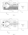
- FIG. 1 shows a conventional two-electrode electrochemical biosensor 100 connected to a generic measurement device 102 such as a test meter.
- the measurement device 102 includes a measuring circuit 102a.
- an electrochemical reaction can take place in the presence of a sample having an analyte of interest.
- a subsequent current value generated by the presence of the analyte then can be detected by the measurement device 102 and can be analyzed to determine an analyte concentration in the sample.
- the measurement device 102 can apply a potential difference of V 1 between the biosensor's contact with working electrode (WE) trace 110 and counter electrode (CE) trace 108 and measure a generated loop current (I LOOP ).
- WE working electrode
- CE counter electrode
- the measurement device 102 further can compute impedance (Z) of a load or a cell by V 1 /I LOOP .
- impedances for a WE trace 110 and/or a CE trace 108 can impact the overall impedance calculations. If the current and trace resistances are small, however, the current ⁇ resistance (I ⁇ R) losses associated with the biosensor 100 connections and traces remain small. In this instance of low resistance connecting traces, the potential at the load, V 2 , will be approximately equal to V 1 , and the computation accuracy is unaffected by I ⁇ R losses.
- I LOOP can be kept small by reducing
- is not within the measurement device's control since it is determined as a property of the biosensor's design and as properties of a sample (e.g., a biosensor with a lower loop resistance).
- Trace resistance on a planar substrate can be kept small by using highly conductive (i.e., metallic) materials, by keeping the traces wide, and/or by keeping the traces thick.
- highly conductive i.e., metallic
- Kelvin connections have been known and used as an electrical impedance measurement technique.
- Such a measurement technique employs separate pairs of current-carrying traces and voltage-sensing (or reference) traces to enable more accurate measurements of unknown load impedances (i.e. , four-terminal sensing).
- Adding one or more remotely connected voltage-sensing traces to one or more electrodes allows an excitation circuit to detect the potential available at or near the load.
- This arrangement allows the measuring circuit to adjust V 1 to compensate for I ⁇ R losses in current-carrying paths of conductive elements and connections between the voltage source and load.
- a measuring circuit's excitation can be configured to dynamically adjust V 1 potential over a wide range of trace and load resistances based on a difference between desired and sensed potentials.
- FIGS. 2-3 show a conventional two-electrode electrochemical biosensor 200 having a sample receiving chamber 114, where the biosensor 200 is connected to a generic measurement device 102 such as a test meter.
- the biosensor 200 includes one Kelvin connection in the form of a WE voltage-sensing trace 112 in electrical communication with an end of the WE 104.
- the biosensor's conductive elements can be made narrower by decreasing, for example, the WE trace 110 width.
- the biosensor 200 may be made less expensive by reducing the WE trace 110 thickness or by making the WE trace 110 from a more resistive material. I ⁇ R losses along the CE trace 108 will have the same impact on V 2 error as in FIG. 1 .
- a measuring circuit sense input should have a high input impedance, ideally limiting the WE sense trace 112 current to 0 nA. Additional voltage-sensing traces also can be used. See, e.g., FIG. 4 ; as well as US Patent No.
- Voltage-sensing traces have limits. For example, physical, economic or practical considerations may restrict where voltage-sensing traces are connected to a biosensor's conductive elements, and therefore how accurately these leads represent the true operating potential at the active load. Moreover, additional (e.g., uncompensated) trace resistance 'after' or 'outside' any voltage-sensing trace connections may become a significant source of load impedance calculation error as the measured current increases, the load impedance decreases or the trace resistance increases or varies.
- US2009223817 A1 discloses a biosensor with a working and a counter electrode and a Kelvin connection (four-wire connection) in figure 27. Voltage Vp1 is applied to the WE and voltage Vml is applied to the CE. A reference line for the WE with voltage Vp2 with a high input impedance is present, therewith the current flowing through WE reference terminal 213b is substantially zero. The same applies for the CE and terminal 214b. However, no further compensation is mentioned therein.
- R UNC uncompensated resistance
- This disclosure is directed toward improving electrochemical analyte measurement accuracy and reliability of analyte measurement systems in view of R UNC that may be present in biosensors having conductive elements with low conductivity or having conductive elements with highly variable sheet resistances.
- An inventive concept herein is achieved by segmenting areas of the conductive elements (e.g., CE and WE) of biosensors into a theoretical number of conductive "squares," respectively, and using this information to calculate or determine R s of a biosensor in ⁇ /square at a time of use by measuring resistance of one or more paths or patterns of the conductive elements and dividing by the theoretical number of conductive squares in that path or pattern of conductive elements (i.e., one or more compensation loops formed by voltage-sensing traces).
- conductive elements e.g., CE and WE
- a value for R UNC is then obtained by multiplying R s by a number of theoretical, uncompensated conductive squares 'after,' 'beyond' or 'outside' that pattern or path of conductive elements used to determine R s .
- Measurement errors can be compensated, corrected and/or minimized by subtracting R UNC from a real portion of a measured impedance.
- a method, according to the present invention, of compensating, correcting or minimizing uncompensated resistances in a biosensor is defined in claim 1.
- a blood glucose meter, according to the present invention, for compensating, correcting or minimizing uncompensated resistances in a biosensor is defined in claim 4. Further embodiments of the present invention are defined in the dependent claims.
- methods are provided for compensating, correcting and/or minimizing effects of R UNC in the conductive elements of biosensors during electrochemical analyte measurements.
- Such methods include providing a biosensor having one or more conductive elements, where such conductive elements comprise a WE, a WE trace, a WE contact pad, a WE voltage-sensing trace, a WE voltage-sensing contact pad, a CE, a CE trace, a CE contact pad, a CE voltage-sensing trace, and a CE voltage-sensing contact pad.
- the methods also include applying or providing a potential to the conductive elements and then measuring resistance of at least one structure of the conductive elements with at least two contacts.
- the resistance is a resistance of at least one compensation loop that includes a voltage-sensing trace.
- the applied or provided potential includes one or more alternating current (AC) components.
- the one or more AC components include at least a 20 kHz segment.
- the one or more AC components include a sequence of a first 10 kHz segment, a 20 kHz segment, a second 10 kHz segment, a 2 kHz segment, and a 1 kHz segment.
- the applied or provided potential further includes one or more direct current (DC) components.
- the methods also include determining R s for one or more compensation loops present in the conductive elements, where the one or more compensation loops include a voltage-sensing connection.
- R s can be calculated by measuring resistance of the one or more compensation loops and dividing the measured loop resistance by a number of conductive squares therein.
- the methods also include determining R UNC for resistance(s) 'after,' 'beyond' or 'outside' voltage-sensing trace connections to the conductive elements of such biosensors.
- R UNC can be calculated by multiplying R s by a number of uncompensated conductive squares present in the path or pattern of conductive elements 'after,' 'beyond' or 'outside' any voltage-sensing trace connections (i.e., after, beyond or outside the compensation loop).
- the methods also include adjusting, compensating and/or minimizing effects of the R UNC by subtracting R UNC from a real portion of a measured impedance.
- the methods also include determining a concentration of an analyte of interest in view of the adjusted, compensated and/or minimized R UNC .
- Such devices can be a test meter having at least a programmable processor associated with a controller/microcontroller that is connected with memory and associated test signal generating and measuring circuitry that are operable to generate a test signal, to apply the signal to a biosensor, and to measure one or more responses of the biosensor to the test signal, where the test meter is configured to execute the methods as described herein.
- Such systems can include the test meter as described herein and at least one biosensor for use therein.
- the devices, systems and methods described herein therefore find use in monitoring and treating diseases and disorders, as well as find use in adjusting a treatment for a disease or disorder.
- indefinite article “a” or “an” does not exclude the possibility that more than one element is present, unless the context clearly requires that there be one and only one element.
- the indefinite article “a” or “an” thus usually means “at least one.”
- the terms “have,” “comprise” or “include” or any arbitrary grammatical variations thereof are used in a non-exclusive way. Thus, these terms may both refer to a situation in which, besides the feature introduced by these terms, no further features are present in the entity described in this context and to a situation in which one or more further features are present.
- the expressions "A has B,” “A comprises B” and “A includes B” may refer both to a situation in which, besides B, no other element is present in A (i.e., a situation in which A solely and exclusively consists of B) or to a situation in which, besides B, one or more further elements are present in A, such as element C, elements C and D, or even further elements.
- This disclosure is directed toward compensating, correcting and/or minimizing for effects of R UNC that often is present in the conductive elements of biosensors for electrochemical analyte measurement systems.
- R UNC that can be present 'after,' 'beyond' or 'outside' Kelvin (i.e., voltage-sensing trace) connections in the conductive elements of biosensors and can minimize the active potential error.
- R UNC cannot be entirely eliminated through careful electrode cell design.
- portions 616, 620, 624 and 618, 622 and 626 of FIGS. 7 and 9 represent areas of the conductive elements considered 'after,' 'beyond' or 'outside' points X and Y that contribute to R UNC .
- an ideal biosensor design can be restricted by system requirements, physical size, cost constraints, and even design complexity.
- the R s of printed or sputtered conductive films is difficult to precisely control and may vary from lot to lot.
- resistance changes in small uncompensated regions can influence impedance measurements in electrochemical-based analyte detections.
- R s can vary based on the material used and on the thickness of the material applied to the substrate.
- gold is used as a trace material, which can be applied to a substrate using a metal sputtering process.
- gold can be used alone as a trace material such as, for example, a 500 ⁇ gold layer.
- the gold layer can have a sensitivity to thickness and sputtering time of approximately -0.032 ( ⁇ /sq)/nm.
- 100 ⁇ can make the trace more sensitive to variations in thickness and sputtering time ( e.g. , -0.8 ( ⁇ /sq)/nm).
- a thicker material can allow for less variation in resistance across the trace, making estimations of the given resistance per/square less sensitive to these variations.
- hybrid materials can be used to provide suitable variations in impedance while reducing material cost.
- One such hybrid material is a gold/palladium composite.
- a 100 ⁇ gold layer can be deposited over a 300 ⁇ layer of palladium.
- This hybrid material generally has a R s of 4.2 ⁇ /square, whereas a 500 ⁇ layer of gold generally has a R s of 1.59 ⁇ /square.
- a gold/palladium hybrid trace material can exhibit a linear increase in resistance with increasing temperature. For example, for the 100 ⁇ gold layer over the 300 ⁇ palladium layer, the resistance increase can average about +4.22 m ⁇ /square/°C.
- broad field laser ablation can produce biosensors having planar conductive elements in thin metal layers with reasonable accuracy and precision.
- the dimensional precision is sufficient to allow one to determine R s of one or more conductive elements of a biosensor in ⁇ /square at time of use by measuring the resistance of one or more selected areas in the conductive elements, such as a compensation loop (i.e., CE contact pad, CE trace, CE voltage-sensing trace and CE voltage-sensing contact pad and/or WE contact pad, WE trace, WE voltage-sensing trace and WE voltage-sensing contact pad) and dividing by a theoretical number of conductive 'squares' therein.
- sheet resistance or "R s means a concept that applies to uniform conductive layers sufficiently thin to be considered two dimensional (length (L) and width (W); as thickness (T) ⁇ L and W).
- R resistance of such a conductive layer/sheet
- R ( ⁇ ) R s ⁇ (L/W)
- R s R s ⁇ (L/W)
- R UNC R UNC then can be predicted by multiplying R s by the theoretical number of uncompensated conductive squares in the conductive path of the biosensor that is 'after,' 'beyond' or 'outside' the voltage-sensing trace connections to the CE and/or WE, respectively, as shown below in Equation 1.
- conductive square or “conductive squares” mean a theoretically designated or defined area in the conductive elements of a biosensor, which is a unitless measure of an aspect ratio of a conductive path in the conductive elements, broken down into the number of squares (based on the width) that can be experimentally or theoretically determined in uncompensated and active portions of the conductive path. In one sense, the effective surface area of the conductive path is approximated as a number of squares.
- the number of squares in the conductive elements can be an even number or an odd number of squares and also can include fractions. The number of squares, however, will be limited by the overall geometry of the conductive elements as it is based upon the area (e.g., L ⁇ W for rectangular geometries) thereof.
- the number of conductive squares in the biosensor's conductive elements may be estimated, calculated or determined experimentally.
- parasitic resistance is unintentional additional resistance responsible for a potential (i.e., voltage) drop that is undesirable along a length of the conductive elements (e.g. , electrodes, traces, and contact pads, etc. ) of a biosensor. Consequently, the potential presented to the measurement electrodes (e.g., CE and WE) in a reaction zone is notably less than the potential applied across contact pads of the biosensor by a measurement device such as a test meter.
- parasitic resistance can be compensated within a biosensor design by using voltage-sensing connections that can be used to dynamically adjust the applied potential of the measurement device to achieve the desired potential at the point of the sensing connection.
- uncompensated resistance or "R UNC” means a parasitic resistance that is not corrected by means of voltage-sensing connections. Because the impedance of the reaction taking place within the reaction zone can be within an order of magnitude of the R UNC of the biosensor, a signal being measured can have a significant offset due to the I ⁇ R drop induced by the R UNC . If this offset varies from biosensor to biosensor, then noise or error will be included in the measurement results.
- any conductive path may alter the length or width thereof (thus changing the number of "squares") or one may alter the thickness or material of a conductive layer (thus changing the R s ) to increase or decrease a predicted resistance value for that particular conductive path to fall within a desired range of resistance values. Determining the number of squares for a particular conductive path in a variety of patterns and configurations other than generally straight line paths is within the ordinary skill in the art and requires no further explanation here.
- test systems and methods herein can be used to implement a variety of calibrations, compensations, or corrections that can be tailored to a specific biosensor or test system and the operational parameters for the system to improve an electrochemical measurement's accuracy and reliability.
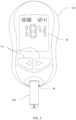
- Test systems herein can include a measurement device and one or more biosensors. Although the methods described herein may be used with measurement devices and biosensors having a wide variety of designs and made with a wide variety of manufacturing processes and techniques, an exemplary test system including a measurement device 102 such as a test meter operatively coupled with an electrochemical biosensor 100 is shown in FIG. 5 .
- the measurement device 102 and the biosensor 100 are operable to determine concentrations of one or more analytes of interest in a sample provided to the biosensor 100.
- the sample may be a body fluid sample such as, for example, whole blood, plasma, saliva, serum, sweat, or urine.
- the sample may be another type of fluid sample to be tested for the presence or concentration of one or more electrochemically reactive analyte(s) such as an aqueous environmental sample.
- the biosensor 100 is a single use test element removably inserted into a connection terminal (or biosensor port) 40 of the measurement device 102.
- biosensor means a device capable of qualitatively or quantitatively detecting one or more analytes of interest on the basis of, for example, a specific reaction or property of a fluidic sample having or suspected of having the analyte of interest.
- Biosensors also called test elements, may be classified into electrical-based sensors, magnetic-based sensors, mass-based sensors, and optical-based sensors according to a detection method associated therewith. Of particular interest herein are electrical-based sensors, especially electrochemical sensors.
- the biosensor 100 is configured as a dual analyte, such as glucose and ketone, biosensor and includes features and functionalities for electrochemically measuring glucose and ketones. See, e.g., Int'l Patent Application Publication Nos. WO 2014/068024 and WO 2014/068022 .
- the biosensor 100 is configured to electrochemically measure other analytes such as, for example, amino acids, antibodies, bacteria, carbohydrates, drugs, lipids, markers, nucleic acids, peptides, proteins, toxins, viruses, and other analytes.
- the measurement device 102 generally includes an entry (or input) means 44, a controller, a memory associated with the controller/microcontroller, and a programmable processor associated with the controller and connected with the memory (not shown).
- the measurement device 102 includes an output such as an electronic display 42 that is connected to the processor and is used to display various types of information to the user including analyte concentration(s) or other test results.
- the measurement device 102 includes associated test signal generating and measuring circuits (not shown) that are operable to generate a test signal, to apply the signal to the biosensor 100, and to measure one or more responses of the biosensor 100 to the test signal.
- the processor also is connected with the connection terminal 40 and is operable to process and record data in memory relating to detecting the presence and/or concentration of the analytes obtained through use of one or more biosensors 100.
- the connection terminal 40 includes connectors configured to engage with contact pads of the conductive elements.
- the measurement device 102 includes user entry means connected with the processor, which is accessible by a user to provide input to processor, where the processor is further programmable to receive input commands from user entry means and provide an output that responds to the input commands.
- the processor also is connected with a communication module or link to facilitate wireless transmissions with the measurement device 102.
- the communication link may be used to exchange messages, warnings, or other information between the measurement device 102 and another device or party, such as a caseworker, caregiver, parent, guardian or healthcare provider, including nurses, pharmacists, primary or secondary care physicians and emergency medical professionals, just to provide a few possibilities.
- the communication link also can be utilized for downloading programming updates for the measurement device 102.
- the communication link may be configured for sending and receiving information through mobile phone standard technology, including third-generation (3G) and fourth-generation (4G) technologies, or through BLUETOOTH ® , ZIGBEE ® , Wibree, ultra-wide band (UWB), wireless local area network (WLAN), General Packet Radio Service (GPRS), Worldwide Interoperability for Microwave Access (WiMAX or WiMAN), Wireless Medical Telemetry (WMTS), Wireless Universal Serial Bus (WUSB), Global System for Mobile communications (GSM), Short Message Service (SMS) or WLAN 802.11x standards.
- 3G third-generation
- 4G fourth-generation
- Wibree ultra-wide band
- WLAN wireless local area network
- GPRS General Packet Radio Service
- WiMAX or WiMAN Worldwide Interoperability for Microwave Access
- WMTS Wireless Medical Telemetry
- WUSB Wireless Universal Serial Bus
- GSM Global System for Mobile communications
- SMS Short Message Service
- WLAN 802.11x standards.
- the controller therefore can include one or more components configured as a single unit or of multi-component form and can be programmable, a state logic machine or other type of dedicated hardware, or a hybrid combination of programmable and dedicated hardware.
- One or more components of the controller may be of the electronic variety defining digital circuitry, analog circuitry, or both.
- the controller may include one or more mechanical or optical control elements.
- the controller includes an integrated processor operatively coupled to one or more solid-state memory devices defining, at least in part, memory.
- the memory contains operating logic to be executed by processor that is a microprocessor and is arranged for reading and writing of data in the memory in accordance with one or more routines of a program executed by the microprocessor.
- the memory can include one or more types of solid-state electronic memory and additionally or alternatively may include the magnetic or optical variety.
- the memory can include solid-state electronic random access memory (RAM), sequentially accessible memory (SAM) (such as the "First-In, First-Out” (FIFO) variety or the “Last-In First-Out” (LIFO) variety), programmable read only memory (PROM), electrically programmable read only memory (EPROM), or electrically erasable programmable read only memory (EEPROM); or a combination of any of these types.
- the memory may be volatile, nonvolatile or a hybrid combination of volatile and nonvolatile varieties. Some or all of the memory can be of a portable type, such as a disk, tape, memory stick, cartridge, code chip or the like. Memory can be at least partially integrated with the processor and/or may be in the form of one or more components or units.
- the measurement device 102 may utilize a removable memory key, which is pluggable into a socket or other receiving means and which communicates with the memory or controller to provide information relating to calibration codes, measurement methods, measurement techniques, and information management. Examples of such removable memory keys are disclosed in US Patent Nos. 5,366,609 and 5,053,199 .
- the controller also can include signal conditioners, filters, limiters, analog-to-digital (A/D) converters, digital-to-analog (D/A) converters, communication ports, or other types of operators as would occur to one of skill in the art.
- A/D analog-to-digital
- D/A digital-to-analog
- entry means 44 it may be defined by a plurality of push-button input devices, although the entry means 44 may include one or more other types of input devices like a keyboard, mouse or other pointing device, touch screen, touch pad, roller ball, or a voice recognition input subsystem.
- the display 42 may include one or more output means like an operator display that can be of a cathode ray tube (CRT) type, liquid crystal display (LCD) type, plasma type, light emitting diode (LED) type, organic light emitting diode (OLED) type, a printer, or the like.
- output means like an operator display that can be of a cathode ray tube (CRT) type, liquid crystal display (LCD) type, plasma type, light emitting diode (LED) type, organic light emitting diode (OLED) type, a printer, or the like.
- Other input and display means can be included such as loudspeakers, voice generators, voice and speech recognition systems, haptic displays, electronic wired or wireless communication subsystems, and the like.
- connection terminal 40 includes connectors configured to engage with contact pads of the conductive elements of the biosensors described herein.
- the connection between the measurement device 102 and the biosensor 100 is used to apply a test signal having a potential or a series of potentials across the electrodes of the conductive elements and to subsequently receive electrochemical signals that are produced by the detection reagents in the presence of the analytes of interest and can be correlated to the concentration of the analytes.
- the processor is configured to evaluate the electrochemical signals to assess the presence and/or concentration of the analyte, where the results of the same may be stored in the memory.
- the measurement device 102 can be configured as a blood glucose measurement meter and includes features and functionalities of the ACCU-CHEK ® AVIVA ® meter as described in the booklet " Accu-Chek® Aviva Blood Glucose Meter Owner's Booklet” (2007 ), portions of which are disclosed in US Patent No. 6,645,368 .
- measurement device 102 can be configured to electrochemically measure one or more other analytes such as, for example, amino acids, antibodies, bacteria, carbohydrates, drugs, lipids, markers, nucleic acids, proteins, peptides, toxiris, viruses, and other analytes. Additional details regarding exemplary measurement devices configured for use with electrochemical measurement methods are disclosed in, for example, US Patent Nos.
- test systems include one more biosensors 10, 100 or 200 as illustrated schematically in FIGS. 2-4 and 6 .
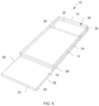
- a non-conductive support substrate 12 of the biosensor 10 includes a first surface 18 facing the spacer 14 and a second surface 20 opposite the first surface 18. Moreover, the support substrate 12 has opposite first and second ends 22, 24 and opposite side edges 26, 28 that extend between the first and second ends 22, 24. In some instances, the first and second ends 22, 24 and the opposite side edges 26, 28 of the support substrate 12 form a generally rectangular shape. Alternatively, the first and second ends 22, 24 and the opposite side edges 26, 28 may be arranged to form any one of a variety of shapes and sizes that enable the biosensor 10 to function as described herein.
- the support substrate 12 can be fabricated of a flexible polymer including, but not limited to, a polyester or polyimide, such as polyethylene naphthalate (PEN) or polyethylene terephthalate (PET).
- PEN polyethylene naphthalate
- PET polyethylene terephthalate
- the support substrate 12 can be fabricated from any other suitable materials that enable the support substrate 12 to function as described herein.
- the electrical conductor may be fabricated from materials including, but not limited to, aluminum, carbon (e.g., graphite), cobalt, copper, gallium, gold, indium, indium, iron, lead, magnesium, mercury (as an amalgam), nickel, niobium, osmium, palladium, platinum, rhenium, rhodium, selenium, silicon (e.g., highly doped polycrystalline silicon), silver, tantalum, tin, titanium, tungsten, uranium, vanadium, zinc, zirconium, and combinations thereof.
- the conductive elements are isolated from the rest of the electrical conductor by laser ablation or laser scribing, both of which are well known in the art.
- the conductive elements can be fabricated by removing the electrical conductor from an area extending around the electrodes either broadly, such as by broad field ablation, or minimally, such as by line scribing.
- the conductive elements may be fabricated by other techniques such as, for example, lamination, screen-printing, photolithography, etc.
- biosensor 10 has a full width end dose (“FWED") capillary channel 30 that is bounded only on one side and is located at the first end 22 of the support substrate.
- FWED full width end dose
- the capillary channel 30 also can be a conventional capillary channel (i.e., bounded on more than one side).
- the spacer 14 extends between the opposite side edges 26, 28 of the support substrate 12 to form the capillary channel 30 in part with a cover. It is contemplated that the spacer 14 may be fabricated of a single component or even a plurality of components. Regardless, the spacer 14 should include an end edge 32 substantially parallel to and facing the first end 22 of the support substrate 12, thereby defining a boundary of a capillary channel 30 by extending across the entire width of the support substrate 12.
- the end edge 32 may include multiple portions located between the first and second ends 22, 24 and the opposite side edges 26, 28 of the support substrate 12 to form a generally U-shaped pattern to define the boundary of the capillary channel 30 having a sample inlet at the first end 22 of the test element 10 (not shown).
- Other suitable embodiments contemplate an end edge 28 that forms hemi-ovular, semi-circular, or other shaped capillary channels, and the one or more of the portions of end edge 32 may include linear or non-linear edges along all or part of its length (not shown).
- the spacer 14 is fabricated from an insulative material such as, for example, a flexible polymer including an adhesive-coated polyethylene terephthalate (PET)-polyester.
- a suitable material includes a PET film, both sides of which can be coated with a pressure-sensitive adhesive.
- the spacer 14 may be constructed of a variety of materials and includes an inner surface 34 that may be coupled to the first surface 18 of the support substrate 12 using any one or a combination of a wide variety of commercially available adhesives. Additionally, when first surface 18 of the support substrate 12 is exposed and not covered by the electrical conductor, the cover 16 may be coupled to support the substrate 12 by welding, such as heat or ultrasonic welding. It also is contemplated that first surface 18 of the support substrate 12 may be printed with, for example, product labeling or instructions (not shown) for use of the test elements 10.
- the spacer 14 can be omitted, and the capillary chamber 30 can be defined only by the support substrate 12 and the cover 16. See, e.g., US Patent No. 8,992,750 .
- the cover 16 extends between the opposite side edges 26, 28 of the support substrate 12 and extends to the first end 22 of the support substrate 12. Alternatively, the cover 16 may extend beyond the first end 22 a predefined distance that enables the biosensor 10 to function as described herein.
- the capillary channel 30 is therefore defined as the space between the cover 16 and the support substrate 12, bounded by the first end 22 and the opposite side edges 26, 28 of the support substrate 12 and the end edge 32 of the spacer 14.
- the cover 16 can be fabricated from an insulative material such as, for example, a flexible polymer including an adhesive-coated PET-polyester.
- a suitable material includes a transparent or translucent PET film.
- the cover 16 may be constructed of a variety of materials and includes a lower surface 36 that may be coupled to the spacer 14 using any one or a combination of a wide variety of commercially available adhesives. Additionally, the cover 16 may be coupled to the spacer 14 by welding, such as heat or ultrasonic welding.
- the biosensors include an electrode system having conductive elements such as, but not limited to, at least one CEIWE electrode pair, one or more electrically conductive pathways or traces, and contact pads or terminals of the electrically conductive material provided on, for example, the first surface of the support such that the electrode systems are co-planar.
- the electrode system can be formed on opposing surfaces such that one electrode system is on the first surface of the support and another electrode system is on an opposing surface of the cover. See, e.g., US Patent No. 8,920,628 .
- the electrically conductive material typically is arranged on the substrate in such a way to provide the one or more conductive elements.
- electrically conductive material may be provided using a number of techniques including chemical vapor deposition, laser ablation, lamination, screen-printing, photolithography, and combinations of these and other techniques.
- One particular method for removing portions of the electrically conductive material include laser ablation or laser scribing, and more particularly broad field laser ablation, as disclosed in, for example, US Patent Nos. 7,073,246 and 7,601,299 .
- the conductive elements can be fabricated by removing electrically conductive material from the substrate either broadly, such as by broad field ablation, or minimally, such as by line scribing.
- the conductive elements may be fabricated by other techniques such as, for example, lamination, screen-printing, photolithography, etc.
- laser ablative techniques typically include ablating a conductive material such as a metallic layer or a multi-layer composition that includes an insulating material and a conductive material (e.g., a metallic-laminate of a metal layer coated on or laminated to an insulating material).
- the metallic layer may contain pure metals, alloys, or other materials, which are metallic conductors.
- metals or metallic-like conductors include, but are not limited to, aluminum, carbon (such as graphite and/or graphene), copper, gold, indium, nickel, palladium, platinum, silver, titanium, mixtures thereof, and alloys or solid solutions of these materials.
- the materials are selected to be essentially unreactive to biological systems, with non-limiting examples including, but not limited to, gold, platinum, palladium, carbon and iridium tin oxide.
- the metallic layer may be any desired thickness that, in one particular form, is about 500 ⁇ .
- ⁇ means within a statistically meaningful range of a value or values including, but not limited to, a stated concentration, length, width, height, angle, weight, molecular weight, pH, sequence identity, time frame, temperature or volume. Such a value or range can be within an order of magnitude, typically within 20%, more typically within 10%, and even more typically within 5% of a given value or range. The allowable variation encompassed by “about” will depend upon the particular system under study, and can be readily appreciated by one of skill in the art.
- exemplary conductive elements can include one or more of a WE, WE trace, and WE contact pad, where the conductive trace portions extend between and electrically couple a WE to its respective contact pad.
- the electrically conductive pathways include one or more of a CE, CE trace, and CE contact pad, where the conductive trace portions extend between and electrically couple a CE and to its respective contact pad.
- a "working electrode” or “WE” means an electrode at which an analyte is electrooxidized or electroreduced with or without the agency of a mediator
- the term “counter electrode” or “CE” means an electrode that is paired with one or more WEs and through which passes an electrochemical current equal in magnitude and opposite in sign to the current passed through the WE.
- CE also includes counter electrodes that also function as reference electrodes (i.e., counter/reference electrodes).
- the conductive elements include one or more voltage-sensing leads (i.e., Kelvin connections), where such leads can be in the form of a WE voltage-sensing (WES) trace in electrical communication (i.e., via a wire) at one end with the WE or WE trace and terminating at its other end at a WES contact pad, as well as a CE voltage-sensing (CES) trace in electrical communication at one end with the CE or CE trace and terminating at its other end at a CES contact pad.
- WE WE voltage-sensing
- CES CE voltage-sensing
- the conductive elements also can include one or more sample sufficiency electrodes (SSE), SSE contact pads, and respective SSE traces that extend between and electrically couple the SSEs and SSE contact pads. If included, the SSEs can be used to implement a number of techniques for determining the sufficiency of a sample applied to the biosensors. See, e.g., Int'l Patent Application Publication No. WO 2014/140170 and WO 2015/187580 .
- the conductive elements also can include one or more integrity electrodes (IE) that can be used to verify that the conductive elements are intact, as described in Int'l Patent Application Publication No. WO 2015/187580 .
- IE integrity electrodes
- the conductive elements also can include an information circuit in the form of a plurality of selectable resistive elements that form a resistance network, as described in Int'l Patent Application Publication No. WO 2013/017218 and US Patent Application Publication No. 2015/0362455 .
- the information encoded in the resistance network can relate to an attribute of the biosensors including, but not limited to, calibration information, biosensor type, manufacturing information and the like.
- Methods herein can include compensating, correcting and/or minimizing for R UNC in the conductive paths of conductive elements of biosensors during electrochemical analyte measurements.
- the methods can include the steps described herein, and these steps may be, but not necessarily, carried out in the sequence as described. Other sequences, however, also are conceivable. Moreover, individual or multiple steps may be carried out either in parallel and/or overlapping in time and/or individually or in multiply repeated steps. Furthermore, the methods may include additional, unspecified steps.
- an inventive concept herein includes improving accuracy and reliability of analyte measurement systems by correcting, compensating, and/or minimizing for R UNC along the conductive paths of the conductive elements of biosensors used in connection with electrochemical measurements by theoretically segmenting areas of the conductive elements (e.g., CE and WE) into a number of conductive squares.
- the methods therefore can include determining one or more R s and then R UNC present in the conductive elements of biosensors, which accounts for the number of conductive squares, and subsequently subtracting R UNC from a real portion of a relevant impedance measurement.
- the R UNC may be used to correct a measured impedance calculation to minimize inaccuracies due to the value or variations in the conductive elements' R s .
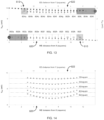
- FIG. 7 shows a simplified diagram of a coplanar, two electrode biosensor 600 having conductive elements such as two voltage-sensing (or reference) traces (indicated by cross-hatch; WE sense trace 602, CE sense trace 604), a WE trace 606, a CE trace 608, a WE 610, a CE 612, and a reaction zone 614 (indicated by light shading).
- conductive elements such as two voltage-sensing (or reference) traces (indicated by cross-hatch; WE sense trace 602, CE sense trace 604), a WE trace 606, a CE trace 608, a WE 610, a CE 612, and a reaction zone 614 (indicated by light shading).
- I LOOP I A -I H ; shown in FIG. 9
- an end 624 of the WE 610, and an end 626 of the CE 612 which are not in contact with a sample within the reaction zone 614, may not contribute to any reaction-dependent current generated between the active portions 620, 622.
- the WE 610 includes uncompensated connecting portion 616, active portion 620, and end 624.
- the CE 612 includes uncompensated connecting portion 618, active portion 622, and end 626.
- the voltage-sensing traces 602, 604 can be coupled to a measurement device, as described above, and can connect to a high input impedance, thereby reducing the current in the voltage-sensing traces 602, 604 to near 0 nA. By reducing or eliminating current flow in the voltage-sensing traces 602, 604, the voltage differential applied at the CE 612 and WE 610 is not affected by the impedance of the voltage-sensing traces 602, 604.
- locations 'X' and 'Y' indicate an area where uncompensated connecting portions 616, 618 of the WE 610 and the CE 612 begin ( i.e., 'after' sense connections, where the sense connections are indicated as points X and Y). Between points X and Y, the true voltage potential difference across a load can be variable and less than the voltage provided by the measuring device (not shown) due to ohmic losses along uncompensated connecting portions 616, 618.
- a measuring circuit 700 can be modelled as collection of resistive elements that includes a first resistor (R WE ) 702 representing the lumped resistance of the uncompensated connecting portion 616 of the WE 610 and a second resistor (R CE ) 704 representing the lumped resistance of the uncompensated connecting portion 618 of the CE 612.
- a load resistor (R LOAD ) 706 represents the true impedance between the uncompensated active portions 620, 622 of the WE 610 and the CE 612.
- a properly designed measuring circuit therefore will attempt to limit currents in the voltage-sensing traces to zero and to maintain a potential difference of V 1 between points X and Y.
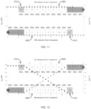
- FIG. 9 shows a simple approximation of the total number of uncompensated conductive squares in the active portions of WE 610 and CE 612, where the undesirable influence of additional resistance is an uncompensated I ⁇ R loss between points X and Y.
- I or R increases, the mean potential difference between the electrodes decreases.
- conductive squares carrying larger currents will have a proportionally larger impact than conductive squares carrying lesser currents.
- the uncompensated connecting portion 616, the uncompensated active portion 620, and end 624 of the WE 610, as well as the uncompensated connecting portion 618, the uncompensated active portion 622, and the end 626 of the CE 612 are theoretically segmented into a number of conductive squares 802, 804.
- these portions can be divided into twelve (12) conductive squares 802a-8021, 804a-804l, respectively.
- the number of conductive squares to which these portions of the CE and WE are divided can and will vary depending upon the architecture of a biosensor's conductive elements.
- the uncompensated connecting portion 616 of the WE 610 can be represented by WE conductive squares 802a-802c, and the uncompensated connecting portion 618 of the CE 612 can be represented by CE conductive squares 804a-804c.
- the uncompensated active portion 620 of the WE 610 can be represented by WE conductive squares 802d-802k, and the uncompensated active portion 622 the CE 612 can be represented and CE conductive squares 804d-804k.
- the end 624 of the WE 610 can be represented by WE conductive square 802l, and the end 626 of the CE 612 can be represented by CE conductive square 604l. As noted above, the ends 624, 626 are not in contact with a sample and therefore do not contribute to any reaction-dependent current that would be generated between the uncompensated active portions 620, 622.
- the entire I LOOP can flow through CE trace 608 and CE conductive squares 804a-804k.
- the I LOOP can be uniformly distributed along eight (8) CE conductive squares 804d-804k, shown as I A -I H .
- the current may not be not symmetrically distributed across CE conductive squares 804d-804k.
- current I H flowing between CE conductive square 804d and WE conductive square 802k can be substantially greater than the current I A flowing between CE conductive square 804k and WE conductive square 802d.
- the current distribution along the WE 610 mirrors the current distribution of the CE 612.
- I LOOP ⁇ A H I N and I A ⁇ I B ⁇ I C ⁇ I D ⁇ I E ⁇ I F ⁇ I G ⁇ I H
- the active current can be evenly divided between the eight (8) conductive squares in each uncompensated active portion 620, 622 (true current will be a linear function of the actual potential difference between the electrodes).
- the total WE current accumulates moving from right to left (i.e., WE conductive squares 802l to 802c) in FIG. 9 .
- the current in WE conductive square 8021 is zero since it is outside the active portion 620.
- the current entering the right edge of WE conductive square 802k is 0, and the current leaving the left edge of square 802k is I H .
- the current leaving the left edge of WE conductive square 802j is [I G +I H ]. This continues through WE conductive square 802d.
- Each uncompensated conductive square in active portion 620 carries a portion of the I LOOP current, increasing as the distance to point X decreases. Approximately 7/8 of I LOOP enters the right edge of WE conductive square 802d, and the entire I LOOP passes through the left edge of WE conductive square 802d.
- the WE of FIG. 9 has three uncompensated connecting squares (802a-c) that carry the entire WE I LOOP current. Since I ⁇ R loss is a primary influence to measurement error, conductive squares carrying only a fraction of I LOOP do not contribute as substantially to potential error as squares carrying the entire loop current.
- the corresponding WE-CE potential difference would be an effectively constant 10 mV, as shown in FIG. 11 .
- real world trace current can be more complex, and may not flow along ideal orthogonal paths.
- FIG. 13 shows the potential difference error using a uniform current distribution in the measurement cell for a R s of 1 ⁇ /square. More specifically, FIG. 14 shows possible potential difference errors for other sheet resistances when measuring a distributed 300 ⁇ load using the exemplary electrode arrangement of FIGS. 7 and 9 . As can be seen, as R s increases so too does the potential drop (not constant over WE and CE conductive squares 802d-802k and 804d-804k, respectively, within WE and CE uncompensated active portions 620, 622).
- electrode cell design and trace connection can reduce an amount of R UNC not accounted for by voltage-sensing traces and can control the active potential error to a desirable value.
- a given biosensor design can be restricted by system requirements, physical size, cost constraints, or design complexity.
- R s of printed or sputtered conductive films can be difficult to precisely control and may vary from lot to lot.
- a typical conductor's R s is a function of electron concentration and mobility. Above 100 K, a metallic conductor's sheet resistance will generally increase linearly with temperature. The opposite is true for carbon or semiconductor materials. For carbon or semiconductor materials, the R s generally decreases (non-linearly) with increasing temperature up to about 250 K. Similar principles can apply to a liquid sample. For example, an increase in solution temperature can decrease its viscosity and increase the mobility of the ions in solution, thereby decreasing its bulk resistance. Precision conductors created from printing or sputtering therefore are generally not cost effective. Additionally, tolerable production variations may impose unacceptable errors in precision impedance measurements. Thus, for improved accuracy and wider measurement ranges, the mechanisms provided herein can be used to correct (at the time of use) measurements of otherwise unknown impedances on biosensors made from low conductivity or highly variable R s conductors.
- the correcting/compensating/minimizing methods described herein thus can be incorporated into known analyte measuring methods to correct uncompensated resistances in the conductive elements of electrochemical biosensors, thereby improving analyte measurement systems that use such biosensors.
- the methods can begin by applying a body fluid having or suspected of having one or more analytes of interest therein to a biosensor.
- the analyte measurement methods include applying a test sequence of one or more potentials to the conductive elements of the biosensor. Such a test sequence can be applied by the measurement device from its connection terminals to one or more contact pads of the conductive elements.
- test sequences include one or more AC components (optional) and/or one or more DC components as are known in the art. See, e.g., Int'l Patent Application Publication Nos. WO 2014/140718 ; WO 2014/140164 ; WO 2014/140170 ; WO 2014/140172 ; WO 2014/140173 ; and WO 2014/140177 , as well as US Patent Nos.
- the test sequence therefore should include at least one AC component.
- a component can include a plurality of AC segments such as, for example, from about 2 segments to about 10 segments, from about 3 segments to about 9 segments, from about 4 segments to about 8 segments, from about 5 segments to about 7 segments, or about 6 segments.
- the AC component can include about 2 segments, about 3 segments, about 4 segments, about 5 segments, about 6 segments, about 7 segments, about 8 segments, about 9 segments, or about 10 segments.
- the AC component can have more than 10 segments, that is, about 15 segments, about 20 segments, or about 25 segments.
- the AC component can include 1 segment, where the segment has multiple low-frequency AC signals applied simultaneously.
- the frequency of each signal in each segment of the AC component can be from about 1 kHz to about 20 kHz, from about 2 kHz to about 19 kHz, from about 3 kHz to about 18 kHz, from about 4 kHz to about 17 kHz, from about 5 kHz to about 16 kHz, from about 6 kHz to about 15 kHz, from about 7 kHz to about 14 kHz, from about 8 kHz to about 13 kHz, from about 9 kHz to about 12 kHz or from about 10 kHz to about 11 kHz.
- the frequency of each segment in the AC component can be about 1 kHz, about 2 kHz, about 3 kHz, about 4 kHz, about 5 kHz, about 6 kHz, about 7 kHz, about 8 kHz, about 9 kHz, about 10 kHz, about 11 kHz, about 12 kHz, about 13 kHz, about 14 kHz, about 15 kHz, about 16 kHz, about 17 kHz, about 18 kHz, about 19 kHz, or about 20 kHz.
- the frequency of each signal in each segment of the AC component can be more than 20 kHz, that is, about 30 kHz, about 40 kHz, or about 50 kHz.
- one or more of the segments can have the same frequency, whereas in other instances each segment has a distinct frequency from the other segments.
- Four frequencies generally is adequate. The exact frequencies employed can be readily generated by simple integer division of a measurement system clock's maximum frequency.
- a maximum frequency limit for a signal in a segment of the AC component can be up to about 100 kHz for an inexpensive, battery-powered handheld instrument such as the meter. Beyond that, the increasing demands on analog bandwidth, sampling rate, storage and processing speed quickly add up, while the imaginary portion of a typical biosensor response becomes increasingly smaller with frequency. Lower frequencies have longer periods and take longer times to sample with comparable accuracy.
- the AC component typically includes at least two (2) different low-amplitude signals.
- the AC component can include two (2) segments at two (2) frequencies such as, for example, about 10 kHz or about 20 kHz followed by about 1 kHz or about 2 kHz.
- the AC component includes a plurality of low-amplitude signals.
- the AC component can have five (5) segments at four (4) frequencies such as, for example, about 10 kHz, about 20 kHz, about 10 kHz, about 2 kHz and about 1 kHz.
- the AC component can have four (4) segments at four (4) frequencies such as, for example, about 20 kHz, about 10 kHz, about 2 kHz and about 1 kHz.
- the AC component can have four (4) frequencies applied simultaneously at about 10 kHz, about 20 kHz, about 10 kHz, about 2 kHz and about 1 kHz.
- the AC component can have a multi-frequency excitation waveform that simultaneously applies the desired low-amplitude AC signals.
- the AC frequencies may be applied sequentially, or combined and applied simultaneously and analyzed via Fourier Transform.
- the component of low-amplitude AC signals can be applied for about 500 msec to about 1.5 sec, about 600 msec to about 1.25 sec, about 700 msec to about 1000 msec, or about 800 msec to about 900 msec.
- the component of low-amplitude AC signals can be applied for about 500 msec, about 600 msec, about 700 msec, about 800 msec, about 900 msec, about 1000 msec, about 1.25 sec or about 1.5 sec.
- the component of low-amplitude AC signals can be applied for about 100 msec to about 300 msec.
- AC current response information can be obtained at any time during a test sequence. Impedance results at lower frequencies may be influenced by analyte concentration if obtained after an electrochemical cell is DC polarized. In some instances, a series of AC current response measurements can be obtained early in the test sequence. Measurements taken shortly after a fluidic sample is applied to a test element will be influenced by diffusion, temperature and reagent solubility. In other instances, the AC response current measurements can be obtained at a sufficient time after an adequate sample has been applied to allow the response to stabilize, and avoid the transient response in the first second. Likewise, response current measurements can be made at one or more frequencies. Due to their capacitive nature, multiple AC measurements separated by a frequency octave or decade may offer different sensitivities or easier manipulation.
- the test sequence also can include one or more DC components.
- a component can include a plurality of pulses such as, for example, from about 2 pulses to about 10 pulses, from about 3 pulses to about 9 pulses, from about 4 pulses to about 8 pulses, from about 5 pulses to about 7 pulses, or about 6 pulses.
- the DC component can include about 2 pulses, about 3 pulses, about 4 pulses, about 5 pulses, about 6 pulses, about 7 pulses, about 8 pulses, about 9 pulses, or about 10 pulses.
- the DC component can have more than 10 pulses, that is, about 15 pulses, about 20 pulses, or about 25 pulses.
- pulse means at least one excitation and one recovery period.
- the DC component typically includes a constantly applied potential difference that alternates between about 0 mV and about +450 mV potential difference, or other slowly time-varying potential difference that can be analyzed by traditional DC electrochemical methods.
- a constantly applied potential difference that alternates between about 0 mV and about +450 mV potential difference, or other slowly time-varying potential difference that can be analyzed by traditional DC electrochemical methods.
- excitation pulse potential can be greater-than, less-than or equal to about +450 mV.
- excitation potentials include, but are not limited to, 50 mV, 75 mV, 100 mV, 125 mV, 150 mV, 175 mV, 200 mV, 225 mV, 250 mV, 275 mV, 300 mV, 325 mV, 350 mV, 375 mV, 400 mV, 425 mV, 450 mV, 475 mV, 500 mV, 525 mV, 550 mV, 575 mV, 600 mV, 625 mV, 650 mV, 675 mV, 700 mV, 725 mV.
- each DC pulse can be applied for about 50 msec to about 500 msec, about 60 msec to about 450 msec, about 70 msec to about 400 msec, about 80 msec to about 350 msec, about 90 msec to about 300 msec, about 100 msec to about 250 msec, about 150 msec to about 200 msec, or about 175 msec.
- each pulse can be applied for about 50 msec, about 60 msec, about 70 msec, about 80 msec, about 90 msec, about 100 msec, about 125 msec, about 150 msec, about 175 msec, about 200 msec, about 225 msec, about 250 msec, about 275 msec, about 300 msec, about 325 msec, about 350 msec, about 375 msec, about 400 msec, about 425 msec, about 450 msec, about 475 msec or about 500 msec.
- each DC pulse at +450 mV can be applied for about 250 msec
- each DC pulse at 0 mV can be applied for about 500 msec.
- each pulse can be applied for less than about 50 msec or more than about 500 msec.
- each DC pulse is selected to provide about 50% or greater reduction in peak current relative to the peak current provided by a nearly ideal potential transition.
- each pulse can have the same ramp rate.
- some pulses can have the same ramp rate and other pulses can have a different ramp rate.
- each pulse has its own ramp rate.
- effective ramp rates can be from about 5 mV/msec to about 75 mV/msec or from about 10 mV/msec to about 50 mV/msec, 15 mV/msec to about 25 mV/msec, or about 20 mV/msec.
- the ramp rate can be about 5 mV/msec, about 10 mV/msec, about 15 mV/msec, about 20 mV/msec, about 25 mV/msec, about 30 mV/msec, about 35 mV/msec, about 40 mV/msec, about 45 mV/msec, about 50 mV/msec, about 55 mV/msec, about 60 mV/msec, about 65 mV/msec, about 70 mV/msec, or about 75 mV/msec.
- the ramp rate can be from about 40 mV/msec to about 50 mV/msec.
- the applied DC potential can be fixed at about 0 mV between pulses to provide a recovery pulse, thus making it a generally continuous excitation waveform.
- recovery pulse means a zero-potential pulse (e.g., about -10 mV to about +10 mV) applied for an adequately long recovery period in which the electrochemical reaction with the analyte of interested (e.g., glucose) is turned “off,” thereby allowing the system to return to a fixed starting point before subsequent interrogation with another positive DC pulse.
- An exemplary DC component therefore can alternate ( i.e. , pulse) between about 0 mV and about +450 mV (in biamperometric mode).
- an exemplary DC component can alternate between about -450 mV and about +450 mV.
- Important response information includes, but is not limited to, duration, shape and/or magnitude of the current response to an excitation pulse and/or a recovery pulse in the test sequence. Such information can be used not only to determine the analyte concentration but also to correct for interferents such as HCT and temperature but also wetting of the reagent and sample diffusion, as well as variations in detection reagent thickness.
- the analyte concentrations can be determined by algorithms and/or correlations to the amount of redox equivalents (e.g., electrons) liberated or consumed in the detection reagents and measured via the electrode system, where such algorithms and/or correlations are known in the art.
- redox equivalents e.g., electrons
- the analyte measurement methods also can include the correcting/compensating steps described above. That is, the methods also can include determining R s of a biosensor in ⁇ /square at a time of use by measuring resistance of one or more patterns of conductive elements in the form of, for example, conductive squares and then dividing by the theoretical number of uncompensated conductive squares in the pattern of conductive elements to obtain R UNC , which subsequently can be used to correct for uncompensated resistances in the conductive elements.
- the correcting/compensating steps may be carried out by a processor or controller or other components of a measurement device, as a non-limiting example, coupled to a biosensor, such as through the connection terminal (or biosensor port) as shown in FIG. 5 .
- the number of conductive squares in the WE and CE can be estimated, experimentally determined, theoretically identified, or simulated.
- the process includes determining an analyte concentration value.
- the original measurements are replaced with corrected Z' and ⁇ '.
- the process may be repeated if all evaluation criteria have not been considered.
- Some non-limiting criteria may include frequencies or temperature ranges (such as based on temperature readings from a thermistor included in the measurement device). That is, if the above-described steps have not been completed for each frequency or for a range of operating temperature, the process may be repeated.
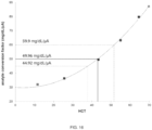
- FIG. 16 shows one example for evaluating operational results from electrochemical biosensors used to analyze a fixed glucose concentration in the presence of varying HCT (e.g., 11.6%, 25.6, 43.4%, 55.0%, 64.6% and 69.8%).
- HCT e.g., 11.6%, 25.6, 43.4%, 55.0%, 64.6% and 69.8%.
- FIG. 16 shows average data from a blood sample and a biosensor having hybrid metal conductive elements with a R s of 4.2 ⁇ /square.
- FIG. 16 therefore shows a demonstrated sensitivity change, which becomes more significant as sample conductivity decreases (lower HCT).
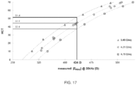
- FIG. 17 shows one example for converting R (or Z REAL ) to HCT that can be used in connection with the data shown in FIG. 16 .
- R s was varied from 0.2, 3.8, 4.2, and 4.8 ⁇ /square, respectively.
- Table 1 shows results from an electrode made with a conductive material of reasonable thickness, where the R s was about 0.2 ⁇ /square. If the electrodes have a low R s , then there essentially is no significant R UNC to be corrected.
- Z REAL corrected glucose is akin to a value uncorrected for R UNC .
- Z REAL therefore is the value that is obtained from the AC component in the exemplary measurement method and is the measured value that would have contributions from both HCT and R UNC . In this case even if the value is corrected for R UNC , the difference is small because R UNC is small.
- Tables 2-4 show results with gradually increasing R s values.
- the test strips have a less conductive thin film electrode and thus are more resistive when compared to test strips from Table 1, which shows how correcting for R UNC can improve the calculated glucose. This is about a range that would be seen with normal manufacturing methods.
Landscapes
- Health & Medical Sciences (AREA)
- Life Sciences & Earth Sciences (AREA)
- Chemical & Material Sciences (AREA)
- Physics & Mathematics (AREA)
- Hematology (AREA)
- Engineering & Computer Science (AREA)
- General Health & Medical Sciences (AREA)
- Biomedical Technology (AREA)
- Pathology (AREA)
- General Physics & Mathematics (AREA)
- Analytical Chemistry (AREA)
- Biochemistry (AREA)
- Immunology (AREA)
- Molecular Biology (AREA)
- Electrochemistry (AREA)
- Chemical Kinetics & Catalysis (AREA)
- Biophysics (AREA)
- Food Science & Technology (AREA)
- Ecology (AREA)
- Urology & Nephrology (AREA)
- Medicinal Chemistry (AREA)
- Surgery (AREA)
- Optics & Photonics (AREA)
- Veterinary Medicine (AREA)
- Emergency Medicine (AREA)
- Public Health (AREA)
- Animal Behavior & Ethology (AREA)
- Medical Informatics (AREA)
- Heart & Thoracic Surgery (AREA)
- Investigating Or Analyzing Materials By The Use Of Electric Means (AREA)
Claims (14)
- Verfahren zum Kompensieren, Korrigieren oder Minimieren unkompensierter Widerstände in einem Biosensor (10, 600) zur Verwendung beim Bestimmen einer Analytkonzentration, wobei das Verfahren die folgenden Schritte umfasst:Anlegen einer Potenzialdifferenz zwischen zwei leitenden Elementen des Biosensors, wobei der Biosensor Folgendes umfasst:ein nicht leitendes Trägersubstrat (12),leitende Elemente, wobei die leitenden Elemente auf einer Oberfläche der nicht leitenden Basis bereitgestellt sind und wobei die leitenden Elemente eine Arbeitselektrode (610), einen Arbeitselektrodenleiterzug (606), eine Arbeitselektrodenkontaktfläche, einen Arbeitselektroden-Spannungserfassungsleiterzug (602), eine Arbeitselektroden-Spannungserfassungskontaktfläche, eine Gegenelektrode (612), einen Gegenelektrodenleiterzug (608), eine Gegenelektrodenkontaktfläche, einen Gegenelektroden-Spannungserfassungsleiterzug (604) und eine Gegenelektroden-Spannungserfassungskontaktfläche umfassen, undein Nachweisreagenz, das ein oder mehrere der leitenden Elemente kontaktiert,wobei die beiden leitenden Elemente die Arbeitselektrode (610) und die Gegenelektrode (612) sind und die Potenzialdifferenz zwischen diesen über den Arbeitselektrodenleiterzug (606) und den Gegenelektrodenleiterzug (608) angelegt wird, wobei die Arbeitselektrode und die Gegenelektrode jeweils einen unkompensierten Anschlussabschnitt (616, 618) und einen unkompensierten aktiven Abschnitt (620, 622) umfassen, wobei die unkompensierten Anschlussabschnitte außerhalb der jeweiligen Spannungserfassungsleiterzuganschlüsse an die Arbeitselektrode und/oder die Gegenelektrode liegen und wobei jeder unkompensierte Anschlussabschnitt und unkompensierte aktive Abschnitt ferner mehrere theoretisch bezeichnete leitende Quadrate (802a-l, 804a-l) umfasst;Bestimmen eines Flächenwiderstands für die Arbeitselektrode und die Gegenelektrode basierend auf der angelegten Potenzialdifferenz durch:Messen von Widerständen von Kompensationsschleifen, die jeweils von dem Arbeitselektroden-Spannungserfassungsleiterzug (602) und von dem Gegenelektroden-Spannungserfassungsleiterzug (604) gebildet werden,Teilen der gemessenen Widerstände jeder der Kompensationsschleifen durch die Anzahl an theoretisch bezeichneten leitenden Quadraten in der jeweiligen Kompensationsschleife undmathematisches Kombinieren der Ergebnisse, um den Flächenwiderstand zu bestimmen, der die leitenden Elemente repräsentiert;Bestimmen unkompensierter Widerstände für die Arbeitselektrode und die Gegenelektrode basierend auf dem Flächenwiderstand und der Anzahl an leitenden Quadraten in den unkompensierten Anschlussabschnitten undmathematisches Kompensieren oder Korrigieren von Impedanz basierend auf den bestimmten unkompensierten Widerständen.
- Verfahren nach Anspruch 1, ferner umfassend den Schritt des Bestimmens einer Analytkonzentration in einer Körperflüssigkeitsprobe mit oder vermutlich mit einem relevanten Analyten, wobei die Körperflüssigkeit in fluidischem Kontakt mit dem Nachweisreagenz steht.
- Verfahren nach Anspruch 1, ferner umfassend:Anwenden einer elektrischen Testsequenz auf zwei leitende Elemente des Biosensors und Messen von Reaktionsinformationen darauf, wobei die elektrische Testsequenz mindestens eine AC-Komponente und mindestens eine DC-Komponente einschließt; undBestimmen einer oder mehrerer Analytkonzentration(en) mit dem Testmessgerät unter Verwendung der Reaktionsinformationen auf die Testsequenz und basierend auf der DC-Komponente und der mathematisch kompensierten oder korrigierten Impedanz.
- Blutzuckermessgerät zum Kompensieren, Korrigieren oder Minimieren unkompensierter Widerstände in einem Biosensor (10, 600) zur Verwendung beim Bestimmen einer Analytkonzentration;wobei der Biosensor Folgendes umfasst:ein nicht leitendes Trägersubstrat (12),leitende Elemente, wobei die leitenden Elemente auf einer Oberfläche der nicht leitenden Basis bereitgestellt sind und wobei die leitenden Elemente eine Arbeitselektrode (610), einen Arbeitselektrodenleiterzug (606), eine Arbeitselektrodenkontaktfläche, einen Arbeitselektroden-Spannungserfassungsleiterzug (602), eine Arbeitselektroden-Spannungserfassungskontaktfläche, eine Gegenelektrode (612), einen Gegenelektrodenleiterzug (608), eine Gegenelektrodenkontaktfläche, einen Gegenelektroden-Spannungserfassungsleiterzug (604) und eine Gegenelektroden-Spannungserfassungskontaktfläche umfassen, undein Nachweisreagenz, das ein oder mehrere der leitenden Elemente kontaktiert,wobei die beiden leitenden Elemente die Arbeitselektrode (610) und die Gegenelektrode (612) sind und die Potenzialdifferenz zwischen diesen über den Arbeitselektrodenleiterzug (606) und den Gegenelektrodenleiterzug (608) angelegt wird, wobei die Arbeitselektrode und die Gegenelektrode jeweils einen unkompensierten Anschlussabschnitt (616, 618) und einen unkompensierten aktiven Abschnitt (620, 622) umfassen, wobei die unkompensierten Anschlussabschnitte außerhalb der jeweiligen Spannungserfassungsleiterzuganschlüsse an die Arbeitselektrode und/oder die Gegenelektrode liegen und wobei jeder unkompensierte Anschlussabschnitt und unkompensierte aktive Abschnitt ferner mehrere theoretisch bezeichnete leitende Quadrate (802a-l, 804a-l) umfasst;wobei das Blutzuckermessgerät zu Folgendem ausgebildet ist:Anlegen einer Potenzialdifferenz zwischen den beiden leitenden Elementen des Biosensors;Bestimmen eines Flächenwiderstands für die Arbeitselektrode und die Gegenelektrode basierend auf der angelegten Potenzialdifferenz durch:Messen von Widerständen von Kompensationsschleifen, die jeweils von dem Arbeitselektroden-Spannungserfassungsleiterzug (602) und von dem Gegenelektroden-Spannungserfassungsleiterzug (604) gebildet werden,Teilen der gemessenen Widerstände jeder der Kompensationsschleifen durch die Anzahl an theoretisch bezeichneten leitenden Quadraten in der jeweiligen Kompensationsschleife undmathematisches Kombinieren der Ergebnisse, um den Flächenwiderstand zu bestimmen, der die leitenden Elemente repräsentiert;Bestimmen unkompensierter Widerstände für die Arbeitselektrode und die Gegenelektrode basierend auf dem Flächenwiderstand und der Anzahl an leitenden Quadraten in den unkompensierten Anschlussabschnitten undmathematisches Kompensieren oder Korrigieren von Impedanz basierend auf den bestimmten unkompensierten Widerständen.
- Blutzuckermessgerät nach Anspruch 4, das ferner zum Bestimmen einer Analytkonzentration in einer Körperflüssigkeitsprobe mit oder vermutlich mit einem relevanten Analyten ausgebildet ist, wobei die Körperflüssigkeit in fluidischem Kontakt mit dem Nachweisreagenz steht.
- Blutzuckermessgerät nach Anspruch 4, das ferner zu Folgendem ausgebildet ist:Anwenden einer elektrischen Testsequenz auf zwei leitende Elemente des Biosensors und Messen von Reaktionsinformationen darauf, wobei die elektrische Testsequenz mindestens eine AC-Komponente und mindestens eine DC-Komponente einschließt; undBestimmen einer oder mehrerer Analytkonzentration(en) mit dem Testmessgerät unter Verwendung der Reaktionsinformationen auf die Testsequenz und basierend auf der DC-Komponente und der mathematisch kompensierten oder korrigierten Impedanz.
- Verfahren nach Anspruch 1 oder Blutzuckermessgerät nach Anspruch 4, wobei das Potenzial mindestens eine Gleichstrom-(DC)-Komponente umfasst.
- Verfahren nach Anspruch 3 oder Anspruch 7 oder Blutzuckermessgerät nach Anspruch 6 oder Anspruch 7, wobei die mindestens eine DC-Komponente eine Vielzahl von Potenzialimpulsen umfasst, die auf oder von etwa 0 V auf etwa +450 mV ansteigen, wobei jeder Impuls durch ein Rückgewinnungsintervall getrennt ist, während dem eine etwa 0 mV Potenzialdifferenz zwischen der Gegenelektrode und der Arbeitselektrode angelegt wird.
- Verfahren nach Anspruch 3 oder Anspruch 7 oder Blutzuckermessgerät nach Anspruch 6 oder Anspruch 7, wobei die mindestens eine DC-Komponente eine Vielzahl von Potenzialimpulsen umfasst, die zwischen etwa -450 mV und etwa +450 mV wechseln.
- Verfahren nach Anspruch 3 oder Blutzuckermessgerät nach Anspruch 6, wobei der relevante Analyt Glukose ist.
- Verfahren nach Anspruch 1 oder Blutzuckermessgerät nach Anspruch 4, wobei das Potenzial mindestens eine Wechselstrom-(AC)-Komponente umfasst.
- Verfahren nach Anspruch 3 oder Anspruch 11 oder Blutzuckermessgerät nach Anspruch 6 oder Anspruch 11, wobei die mindestens eine AC-Komponente Frequenzen von etwa 20 kHz, etwa 10 kHz, etwa 2 kHz und etwa 1 kHz umfasst und wobei jede Frequenz für etwa 0,5 Sekunden bis etwa 1,5 Sekunden angelegt wird.
- System, umfassend das Blutzuckermessgerät nach einem der Ansprüche 4 bis 12 und mindestens einen Biosensor.
- System nach Anspruch 13, wobei das System ein selbstüberwachendes Blutzucker-(SMBG)-System ist.
Applications Claiming Priority (2)
| Application Number | Priority Date | Filing Date | Title |
|---|---|---|---|
| US201662411727P | 2016-10-24 | 2016-10-24 | |
| PCT/US2017/049800 WO2018080637A1 (en) | 2016-10-24 | 2017-09-01 | Methods of correcting for uncompensated resistances in the conductive elements of biosensors, as well as devices and systems |
Publications (3)
| Publication Number | Publication Date |
|---|---|
| EP3529612A1 EP3529612A1 (de) | 2019-08-28 |
| EP3529612A4 EP3529612A4 (de) | 2020-05-20 |
| EP3529612B1 true EP3529612B1 (de) | 2024-12-11 |
Family
ID=62023918
Family Applications (1)
| Application Number | Title | Priority Date | Filing Date |
|---|---|---|---|
| EP17863601.5A Active EP3529612B1 (de) | 2016-10-24 | 2017-09-01 | Verfahren zur korrektur der unkompensierten widerstände in den leitenden elementen von biosensoren sowie vorrichtungen und systeme |
Country Status (7)
| Country | Link |
|---|---|
| US (1) | US12345672B2 (de) |
| EP (1) | EP3529612B1 (de) |
| JP (1) | JP6923647B2 (de) |
| KR (1) | KR102286694B1 (de) |
| CN (1) | CN110383064B (de) |
| TW (1) | TWI657243B (de) |
| WO (1) | WO2018080637A1 (de) |
Families Citing this family (9)
| Publication number | Priority date | Publication date | Assignee | Title |
|---|---|---|---|---|
| CN111448452B (zh) * | 2017-12-14 | 2023-05-23 | 豪夫迈·罗氏有限公司 | 确定关于等效串联电阻的信息的方法和设备 |
| CN109444245B (zh) * | 2018-12-24 | 2021-04-27 | 广州广电计量检测股份有限公司 | 一种循环伏安分析仪的校准系统及其校准方法 |
| AU2020327164B2 (en) * | 2019-08-02 | 2023-02-23 | Bionime Corporation | Micro biosensor and method for reducing measurement interference using the same |
| TWI702392B (zh) * | 2019-12-20 | 2020-08-21 | 財團法人工業技術研究院 | 氣體感測裝置及氣體濃度感測方法 |
| US12144984B2 (en) * | 2020-03-03 | 2024-11-19 | Advanced Neuromodulation Systems, Inc. | Diagnostic circuitry for monitoring and mitigating electromagnetic interference (EMI) in an implantable pulse generator |
| US12082924B2 (en) * | 2020-07-31 | 2024-09-10 | Medtronic Minimed, Inc. | Sensor identification and integrity check design |
| CN112699630B (zh) * | 2020-12-31 | 2023-09-15 | 杭州广立微电子股份有限公司 | 单层连接结构的方块数获取方法及电阻值的计算方法 |
| MX2024006546A (es) * | 2021-11-30 | 2024-06-12 | Trividia Health Inc | Sistemas y metodos para la medicion de la impedancia del hematocrito mediante medicion de cuatro cables. |
| CN120820609A (zh) * | 2025-05-12 | 2025-10-21 | 中国农业科学院北京畜牧兽医研究所 | 多模态生物传感器及其制备方法 |
Citations (1)
| Publication number | Priority date | Publication date | Assignee | Title |
|---|---|---|---|---|
| US20090223817A1 (en) * | 2002-07-02 | 2009-09-10 | Panasonic Corporation | Biosensor, biosensor chip and biosensor device |
Family Cites Families (131)
| Publication number | Priority date | Publication date | Assignee | Title |
|---|---|---|---|---|
| US4008448A (en) | 1975-10-03 | 1977-02-15 | Polaroid Corporation | Solenoid with selectively arrestible plunger movement |
| US4233029A (en) | 1978-10-25 | 1980-11-11 | Eastman Kodak Company | Liquid transport device and method |
| US4225410A (en) | 1978-12-04 | 1980-09-30 | Technicon Instruments Corporation | Integrated array of electrochemical sensors |
| US4323536A (en) | 1980-02-06 | 1982-04-06 | Eastman Kodak Company | Multi-analyte test device |
| DE3228542A1 (de) | 1982-07-30 | 1984-02-02 | Siemens AG, 1000 Berlin und 8000 München | Verfahren zur bestimmung der konzentration elektrochemisch umsetzbarer stoffe |
| US5509410A (en) | 1983-06-06 | 1996-04-23 | Medisense, Inc. | Strip electrode including screen printing of a single layer |
| US5682884A (en) | 1983-05-05 | 1997-11-04 | Medisense, Inc. | Strip electrode with screen printing |
| DE3321783A1 (de) | 1983-06-16 | 1984-12-20 | Boehringer Mannheim Gmbh, 6800 Mannheim | Anordnung zum auswerten eines teststreifens |
| EP0229810B1 (de) | 1985-07-09 | 1991-10-16 | Quadrant Bioresources Limited | Beschützung von proteinen und ähnlichem |
| US5108564A (en) | 1988-03-15 | 1992-04-28 | Tall Oak Ventures | Method and apparatus for amperometric diagnostic analysis |
| US5128015A (en) | 1988-03-15 | 1992-07-07 | Tall Oak Ventures | Method and apparatus for amperometric diagnostic analysis |
| USRE36268E (en) | 1988-03-15 | 1999-08-17 | Boehringer Mannheim Corporation | Method and apparatus for amperometric diagnostic analysis |
| WO1989009397A1 (en) | 1988-03-31 | 1989-10-05 | Matsushita Electric Industrial Co., Ltd. | Biosensor and process for its production |
| US5053199A (en) | 1989-02-21 | 1991-10-01 | Boehringer Mannheim Corporation | Electronically readable information carrier |
| US5508171A (en) | 1989-12-15 | 1996-04-16 | Boehringer Mannheim Corporation | Assay method with enzyme electrode system |
| US4963814A (en) | 1989-12-15 | 1990-10-16 | Boehringer Mannheim Corporation | Regulated bifurcated power supply |
| US4999632A (en) | 1989-12-15 | 1991-03-12 | Boehringer Mannheim Corporation | Analog to digital conversion with noise reduction |
| US4999582A (en) | 1989-12-15 | 1991-03-12 | Boehringer Mannheim Corp. | Biosensor electrode excitation circuit |
| DE69020908T2 (de) | 1989-12-15 | 1996-02-15 | Boehringer Mannheim Corp., Indianapolis, Ind. | Redox-vermittlungs-reagenz und biosensor. |
| US5243516A (en) | 1989-12-15 | 1993-09-07 | Boehringer Mannheim Corporation | Biosensing instrument and method |
| DE4003194A1 (de) | 1990-02-03 | 1991-08-08 | Boehringer Mannheim Gmbh | Verfahren und sensorelektrodensystem zur elektrochemischen bestimmung eines analyts oder einer oxidoreduktase sowie verwendung hierfuer geeigneter verbindungen |
| US5271895A (en) | 1991-02-27 | 1993-12-21 | Boehringer Mannheim Corporation | Test strip |
| WO1992015950A1 (en) | 1991-02-27 | 1992-09-17 | Boehringer Mannheim Corporation | Method of communicating with microcomputer controlled instruments |
| DE4123348A1 (de) | 1991-07-15 | 1993-01-21 | Boehringer Mannheim Gmbh | Elektrochemisches analysesystem |
| US5371687A (en) | 1992-11-20 | 1994-12-06 | Boehringer Mannheim Corporation | Glucose test data acquisition and management system |
| CH685458A5 (de) | 1993-03-01 | 1995-07-14 | Disetronic Ag | Sensorarray zur selektiven Feststellung oder Messung mindestens einer Stoffkomponente in einer wässerigen Lösung. |
| US5385846A (en) | 1993-06-03 | 1995-01-31 | Boehringer Mannheim Corporation | Biosensor and method for hematocrit determination |
| US5366609A (en) | 1993-06-08 | 1994-11-22 | Boehringer Mannheim Corporation | Biosensing meter with pluggable memory key |
| CA2153883C (en) | 1993-06-08 | 1999-02-09 | Bradley E. White | Biosensing meter which detects proper electrode engagement and distinguishes sample and check strips |
| US5405511A (en) | 1993-06-08 | 1995-04-11 | Boehringer Mannheim Corporation | Biosensing meter with ambient temperature estimation method and system |
| US5352351A (en) | 1993-06-08 | 1994-10-04 | Boehringer Mannheim Corporation | Biosensing meter with fail/safe procedures to prevent erroneous indications |
| ES2154249T3 (es) | 1993-06-21 | 2001-12-16 | Roche Diagnostics Corp | Estabilizador de reactivos de diagnostico. |
| US5413690A (en) | 1993-07-23 | 1995-05-09 | Boehringer Mannheim Corporation | Potentiometric biosensor and the method of its use |
| US5526111A (en) | 1993-08-31 | 1996-06-11 | Boehringer Mannheim Corporation | Method and apparatus for calculating a coagulation characteristic of a sample of blood a blood fraction or a control |
| US5762770A (en) | 1994-02-21 | 1998-06-09 | Boehringer Mannheim Corporation | Electrochemical biosensor test strip |
| US5437999A (en) | 1994-02-22 | 1995-08-01 | Boehringer Mannheim Corporation | Electrochemical sensor |
| DE19521019A1 (de) | 1995-06-13 | 1996-12-19 | Boehringer Mannheim Gmbh | Verfahren und Mittel zur gleichzeitigen kolorimetrischen und elektrochemischen Messung eines Analyten |
| US5628890A (en) | 1995-09-27 | 1997-05-13 | Medisense, Inc. | Electrochemical sensor |
| JP3365184B2 (ja) | 1996-01-10 | 2003-01-08 | 松下電器産業株式会社 | バイオセンサ |
| JP2000512762A (ja) | 1996-06-17 | 2000-09-26 | マーキュリー ダイアグノスティックス インコーポレイテッド | 電気化学テスト装置および関連する方法 |
| DE19629655A1 (de) | 1996-07-23 | 1998-01-29 | Boehringer Mannheim Gmbh | Diagnostischer Testträger und Verfahren zur Bestimmung eines Analyts mit dessen Hilfe |
| ES2186003T3 (es) | 1996-10-30 | 2003-05-01 | Amira Medical | Sistema de analisis sincronizado de analito. |
| US5948695A (en) | 1997-06-17 | 1999-09-07 | Mercury Diagnostics, Inc. | Device for determination of an analyte in a body fluid |
| US6054039A (en) | 1997-08-18 | 2000-04-25 | Shieh; Paul | Determination of glycoprotein and glycosylated hemoglobin in blood |
| US6001239A (en) | 1998-09-30 | 1999-12-14 | Mercury Diagnostics, Inc. | Membrane based electrochemical test device and related methods |
| US6144922A (en) | 1997-10-31 | 2000-11-07 | Mercury Diagnostics, Incorporated | Analyte concentration information collection and communication system |
| JP2001521804A (ja) | 1997-10-31 | 2001-11-13 | アミラ メディカル | 被検物質濃度情報の収集及び通信システム |
| DE19753850A1 (de) | 1997-12-04 | 1999-06-10 | Roche Diagnostics Gmbh | Probennahmevorrichtung |
| US6635167B1 (en) | 1997-12-04 | 2003-10-21 | Roche Diagnostics Corporation | Apparatus and method for determining the concentration of a component of a sample |
| DE19753849A1 (de) | 1997-12-04 | 1999-06-10 | Roche Diagnostics Gmbh | Analytisches Testelement mit sich verjüngendem Kapillarkanal |
| DE19753848A1 (de) | 1997-12-04 | 1999-06-10 | Roche Diagnostics Gmbh | Modifikation von Oberflächen zur Steigerung der Oberflächenspannung |
| DE19753847A1 (de) | 1997-12-04 | 1999-06-10 | Roche Diagnostics Gmbh | Analytisches Testelement mit Kapillarkanal |
| US5997817A (en) | 1997-12-05 | 1999-12-07 | Roche Diagnostics Corporation | Electrochemical biosensor test strip |
| DE69819775T2 (de) | 1997-12-19 | 2004-09-23 | Amira Medical, Scotts Valley | Geprägtes teststreifensystem |
| CN1598564B (zh) * | 1997-12-22 | 2010-04-21 | 罗赫诊断手术公司 | 测量仪 |
| US7494816B2 (en) | 1997-12-22 | 2009-02-24 | Roche Diagnostic Operations, Inc. | System and method for determining a temperature during analyte measurement |
| US7407811B2 (en) | 1997-12-22 | 2008-08-05 | Roche Diagnostics Operations, Inc. | System and method for analyte measurement using AC excitation |
| US7390667B2 (en) | 1997-12-22 | 2008-06-24 | Roche Diagnostics Operations, Inc. | System and method for analyte measurement using AC phase angle measurements |
| US5975153A (en) | 1998-02-13 | 1999-11-02 | Roche Diagnostics Corporation | Capillary fill test device with improved fluid delivery |
| DE19814219A1 (de) | 1998-03-31 | 1999-10-07 | Roche Diagnostics Gmbh | Verfahren zur Kontrolle der Insulinmedikation |
| DE19815684A1 (de) | 1998-04-08 | 1999-10-14 | Roche Diagnostics Gmbh | Verfahren zur Herstellung von analytischen Hilfsmitteln |
| US6945955B1 (en) | 1998-05-20 | 2005-09-20 | Disetronic Licensing Ag | Sensor system including a port body |
| DE19840952C1 (de) | 1998-09-08 | 2000-03-23 | Roche Diagnostics Gmbh | LC-Display mit Ausfallkontrolle |
| US6564368B1 (en) * | 1998-10-01 | 2003-05-13 | Call Center Technology, Inc. | System and method for visual application development without programming |
| DE19849008A1 (de) | 1998-10-23 | 2000-04-27 | Roche Diagnostics Gmbh | Spreitschichten, Netzmittel zu ihrer Herstellung und deren Verwendung in Teststreifen |
| US7208119B1 (en) | 2000-03-01 | 2007-04-24 | Roche Diagnostics Operations, Inc. | Hospital meter system |
| US7045054B1 (en) | 1999-09-20 | 2006-05-16 | Roche Diagnostics Corporation | Small volume biosensor for continuous analyte monitoring |
| DE19945828B4 (de) | 1999-09-24 | 2011-06-01 | Roche Diagnostics Gmbh | Analysenelement und Verfahren zur Bestimmung eines Analyten in Flüssigkeit |
| US7276146B2 (en) | 2001-11-16 | 2007-10-02 | Roche Diagnostics Operations, Inc. | Electrodes, methods, apparatuses comprising micro-electrode arrays |
| US7073246B2 (en) | 1999-10-04 | 2006-07-11 | Roche Diagnostics Operations, Inc. | Method of making a biosensor |
| US6767440B1 (en) | 2001-04-24 | 2004-07-27 | Roche Diagnostics Corporation | Biosensor |
| US6662439B1 (en) | 1999-10-04 | 2003-12-16 | Roche Diagnostics Corporation | Laser defined features for patterned laminates and electrodes |
| US6319719B1 (en) | 1999-10-28 | 2001-11-20 | Roche Diagnostics Corporation | Capillary hematocrit separation structure and method |
| US6413395B1 (en) | 1999-12-16 | 2002-07-02 | Roche Diagnostics Corporation | Biosensor apparatus |
| US6627057B1 (en) | 1999-12-23 | 2003-09-30 | Roche Diagnostic Corporation | Microsphere containing sensor |
| US6780296B1 (en) | 1999-12-23 | 2004-08-24 | Roche Diagnostics Corporation | Thermally conductive sensor |
| US6562210B1 (en) | 1999-12-30 | 2003-05-13 | Roche Diagnostics Corporation | Cell for electrochemical anaylsis of a sample |
| US6451264B1 (en) | 2000-01-28 | 2002-09-17 | Roche Diagnostics Corporation | Fluid flow control in curved capillary channels |
| US6406672B1 (en) | 2000-01-28 | 2002-06-18 | Roche Diagnostics | Plasma retention structure providing internal flow |
| US6858433B1 (en) | 2000-04-03 | 2005-02-22 | Roche Diagnostics Operations, Inc. | Biosensor electromagnetic noise cancellation |
| US6413213B1 (en) | 2000-04-18 | 2002-07-02 | Roche Diagnostics Corporation | Subscription based monitoring system and method |
| US6428664B1 (en) | 2000-06-19 | 2002-08-06 | Roche Diagnostics Corporation | Biosensor |
| DE10032015A1 (de) | 2000-07-01 | 2002-01-10 | Roche Diagnostics Gmbh | Testelement-Analysegerät |
| US6488828B1 (en) | 2000-07-20 | 2002-12-03 | Roche Diagnostics Corporation | Recloseable biosensor |
| US6814843B1 (en) | 2000-11-01 | 2004-11-09 | Roche Diagnostics Corporation | Biosensor |
| US6540890B1 (en) | 2000-11-01 | 2003-04-01 | Roche Diagnostics Corporation | Biosensor |
| US6447657B1 (en) | 2000-12-04 | 2002-09-10 | Roche Diagnostics Corporation | Biosensor |
| AT410601B (de) | 2000-12-29 | 2003-06-25 | Hoffmann La Roche | Sensor zur lumineszenz-optischen bestimmung eines analyten sowie reagens, das nach dem fret-prinzip arbeitet |
| DE10119036C1 (de) | 2001-04-18 | 2002-12-12 | Disetronic Licensing Ag | Tauchsensor zur Messung der Konzentration eines Analyten mit Hilfe einer Oxidase |
| US7473398B2 (en) | 2001-05-25 | 2009-01-06 | Roche Diagnostics Operations, Inc. | Biosensor |
| US6814844B2 (en) | 2001-08-29 | 2004-11-09 | Roche Diagnostics Corporation | Biosensor with code pattern |
| US6755949B1 (en) | 2001-10-09 | 2004-06-29 | Roche Diagnostics Corporation | Biosensor |
| US7018843B2 (en) | 2001-11-07 | 2006-03-28 | Roche Diagnostics Operations, Inc. | Instrument |
| US20030116447A1 (en) | 2001-11-16 | 2003-06-26 | Surridge Nigel A. | Electrodes, methods, apparatuses comprising micro-electrode arrays |
| US6866758B2 (en) | 2002-03-21 | 2005-03-15 | Roche Diagnostics Corporation | Biosensor |
| EP1467206A1 (de) | 2003-04-08 | 2004-10-13 | Roche Diagnostics GmbH | Biosensor Vorrichtung |
| US7452457B2 (en) | 2003-06-20 | 2008-11-18 | Roche Diagnostics Operations, Inc. | System and method for analyte measurement using dose sufficiency electrodes |
| US7727467B2 (en) | 2003-06-20 | 2010-06-01 | Roche Diagnostics Operations, Inc. | Reagent stripe for test strip |
| US8148164B2 (en) | 2003-06-20 | 2012-04-03 | Roche Diagnostics Operations, Inc. | System and method for determining the concentration of an analyte in a sample fluid |
| ES2657627T3 (es) | 2003-06-20 | 2018-03-06 | F. Hoffmann-La Roche Ag | Biosensores electroquímicos |
| US7597793B2 (en) | 2003-06-20 | 2009-10-06 | Roche Operations Ltd. | System and method for analyte measurement employing maximum dosing time delay |
| US7488601B2 (en) | 2003-06-20 | 2009-02-10 | Roche Diagnostic Operations, Inc. | System and method for determining an abused sensor during analyte measurement |
| EP1681992B2 (de) | 2003-09-30 | 2015-03-04 | Roche Diagnostics GmbH | Sensor mit verbesserter biokompatibilität |
| DE10346417A1 (de) | 2003-10-07 | 2005-06-02 | Roche Diagnostics Gmbh | Analytisches Testelement umfassend ein Netzwerk zur Bildung eines Kapillarkanals |
| EP1692258A4 (de) * | 2003-11-12 | 2007-03-21 | Xiao Xu | Elektronische echtzeit-zellwahrnehmungssysteme und anwendungen für tests auf zellbasis |
| DE102004007983A1 (de) | 2004-02-18 | 2005-09-08 | Roche Diagnostics Gmbh | Testelement mit Einschicht-Reaktionsfilm |
| US7556723B2 (en) | 2004-06-18 | 2009-07-07 | Roche Diagnostics Operations, Inc. | Electrode design for biosensor |
| US7569126B2 (en) * | 2004-06-18 | 2009-08-04 | Roche Diagnostics Operations, Inc. | System and method for quality assurance of a biosensor test strip |
| US7601299B2 (en) | 2004-06-18 | 2009-10-13 | Roche Diagnostics Operations, Inc. | System and method for coding information on a biosensor test strip |
| GB2417323A (en) | 2004-08-17 | 2006-02-22 | Oxford Biosensors Ltd | A method of operating an electrochemical sensor by applying a time variable potential between the electrodes. |
| US7291107B2 (en) | 2004-08-26 | 2007-11-06 | Roche Diagnostics Operations, Inc. | Insulin bolus recommendation system |
| GB0518527D0 (en) * | 2005-09-10 | 2005-10-19 | Oxford Biosensors Ltd | Scaling factor for an output of an electrochemical cell |
| US7429865B2 (en) | 2005-10-05 | 2008-09-30 | Roche Diagnostics Operations, Inc. | Method and system for error checking an electrochemical sensor |
| US7638095B2 (en) | 2006-02-10 | 2009-12-29 | Roche Diagnostics Operations, Inc. | Personal portable blood glucose meter with replaceable cartridge of test strips |
| TWI385472B (zh) | 2006-11-17 | 2013-02-11 | Hon Hai Prec Ind Co Ltd | 鏡頭模組及鏡頭模組調焦機構 |
| US7751864B2 (en) | 2007-03-01 | 2010-07-06 | Roche Diagnostics Operations, Inc. | System and method for operating an electrochemical analyte sensor |
| US8431408B2 (en) | 2010-10-15 | 2013-04-30 | Roche Diagnostics Operations, Inc. | Handheld diabetes managing device with light pipe for enhanced illumination |
| US9754708B2 (en) | 2011-07-29 | 2017-09-05 | Roche Diabetes Care, Inc. | Encoded biosensors and methods of manufacture and use thereof |
| US8888973B2 (en) * | 2011-07-29 | 2014-11-18 | Roche Diagnostics Operations, Inc. | Encoded biosensors and methods of manufacture and use thereof |
| CN106170555B (zh) | 2012-09-06 | 2019-10-22 | 霍夫曼-拉罗奇有限公司 | 改进的基质稳定性组合物和方法 |
| US8921061B2 (en) | 2012-11-02 | 2014-12-30 | Roche Diagnostics Operations, Inc. | Reagent materials and associated test elements |
| US8920628B2 (en) | 2012-11-02 | 2014-12-30 | Roche Diagnostics Operations, Inc. | Systems and methods for multiple analyte analysis |
| CN105209204B (zh) | 2013-03-11 | 2018-07-27 | 林肯环球股份有限公司 | 在焊接接头中用自动操控执行电弧焊接的电弧焊接系统和方法 |
| CN105283757B (zh) | 2013-03-15 | 2019-04-23 | 豪夫迈·罗氏有限公司 | 对分析物的电化学测量进行防故障的方法以及结合该方法的设备、装置和系统 |
| CN105190299B (zh) | 2013-03-15 | 2018-04-20 | 豪夫迈·罗氏有限公司 | 电化学测量分析物的基于描述符的方法以及结合该方法的设备、装置和系统 |
| JP6352954B2 (ja) | 2013-03-15 | 2018-07-04 | エフ.ホフマン−ラ ロシュ アーゲーF. Hoffmann−La Roche Aktiengesellschaft | 電気化学的な分析物測定において回復パルスからの情報を使用する方法およびデバイス、装置とそれらを組み込むシステム |
| KR101743382B1 (ko) | 2013-03-15 | 2017-06-02 | 에프. 호프만-라 로슈 아게 | 전기화학적 측정 중 높은 항산화제 레벨들을 검출하고 그로부터 분석물질 농도를 페일세이프하는 방법들 뿐만 아니라 상기 방법들을 통합한 기기들, 장치들 및 시스템들 |
| CA2949906C (en) * | 2013-03-15 | 2019-04-02 | F. Hoffmann-La Roche Ag | Methods of scaling data used to construct biosensor algorithms as well as devices, apparatuses and systems incorporating the same |
| CN106461631B (zh) | 2014-06-05 | 2019-06-14 | 豪夫迈·罗氏有限公司 | 用于测试元件完好性的电极布置 |
| TWM515105U (zh) * | 2015-05-21 | 2016-01-01 | 五鼎生物技術股份有限公司 | 電化學試片及含此試片之檢測裝置 |
| CA2992283C (en) * | 2015-08-11 | 2023-03-07 | F. Hoffmann-La Roche Ag | Encoded biosensors and methods of manufacture and use thereof |
-
2017
- 2017-09-01 EP EP17863601.5A patent/EP3529612B1/de active Active
- 2017-09-01 JP JP2019521805A patent/JP6923647B2/ja active Active
- 2017-09-01 KR KR1020197014656A patent/KR102286694B1/ko active Active
- 2017-09-01 WO PCT/US2017/049800 patent/WO2018080637A1/en not_active Ceased
- 2017-09-01 CN CN201780080264.4A patent/CN110383064B/zh active Active
- 2017-10-20 TW TW106136098A patent/TWI657243B/zh active
-
2019
- 2019-04-18 US US16/388,623 patent/US12345672B2/en active Active
Patent Citations (1)
| Publication number | Priority date | Publication date | Assignee | Title |
|---|---|---|---|---|
| US20090223817A1 (en) * | 2002-07-02 | 2009-09-10 | Panasonic Corporation | Biosensor, biosensor chip and biosensor device |
Also Published As
| Publication number | Publication date |
|---|---|
| TW201821793A (zh) | 2018-06-16 |
| EP3529612A4 (de) | 2020-05-20 |
| TWI657243B (zh) | 2019-04-21 |
| KR20190072607A (ko) | 2019-06-25 |
| CN110383064B (zh) | 2021-06-29 |
| WO2018080637A1 (en) | 2018-05-03 |
| CA3041623A1 (en) | 2018-05-03 |
| JP2019533159A (ja) | 2019-11-14 |
| EP3529612A1 (de) | 2019-08-28 |
| CN110383064A (zh) | 2019-10-25 |
| KR102286694B1 (ko) | 2021-08-06 |
| US20200025707A1 (en) | 2020-01-23 |
| JP6923647B2 (ja) | 2021-08-25 |
| US12345672B2 (en) | 2025-07-01 |
Similar Documents
| Publication | Publication Date | Title |
|---|---|---|
| US12345672B2 (en) | Methods of correcting for uncompensated resistances in the conductive elements of biosensors, as well as devices and systems incorporating the same | |
| CN1839313B (zh) | 涉及电化学生物传感器的设备和方法 | |
| US8557104B2 (en) | In vitro analyte sensor, and methods | |
| CN105164523B (zh) | 缩放用于构造生物传感器算法的数据的方法以及合并所述方法的设备、装置和系统 | |
| EP2972271B1 (de) | Deskriptorenbasierte verfahren zur elektrochemischen messung eines analyten | |
| EP3014258B1 (de) | Kurzzeitsignalfehlerfalle für eine analytmessung, definiert aus einer bestimmten abtastzeit aus einer gemessenen physikalischen eigenschaft der probe mit dem analyten | |
| EP3014256B1 (de) | Füllfehlerfalle für eine analytmessung, bestimmt aus einer bestimmten abtastzeit aus einer gemessenen physikalischen eigenschaft der probe mit dem analyt | |
| KR20170106471A (ko) | 지정 샘플링 시간 및 사전결정 샘플링 시간으로부터 결정된 기준 전극 에러 트랩 | |
| CA3041623C (en) | Methods of correcting for uncompensated resistances in the conductive elements of biosensors, as well as devices and systems | |
| HK40016599B (en) | Methods of correcting for uncompensated resistances in the conductive elements of biosensors, as well as devices and systems | |
| HK40016599A (en) | Methods of correcting for uncompensated resistances in the conductive elements of biosensors, as well as devices and systems | |
| US20200033287A1 (en) | Method of operation of a meter | |
| KR20170059472A (ko) | 측정된 온도, 물리적 특성 및 추정된 분석물 값에 기초하여 분석물 측정 시간을 결정하기 위한 전기화학 검사 스트립에 대한 정확한 분석물 측정 | |
| HK1218777B (en) | Methods of scaling data used to construct biosensor algorithms as well as devices, apparatuses and systems incorporating the same |
Legal Events
| Date | Code | Title | Description |
|---|---|---|---|
| STAA | Information on the status of an ep patent application or granted ep patent |
Free format text: STATUS: THE INTERNATIONAL PUBLICATION HAS BEEN MADE |
|
| PUAI | Public reference made under article 153(3) epc to a published international application that has entered the european phase |
Free format text: ORIGINAL CODE: 0009012 |
|
| STAA | Information on the status of an ep patent application or granted ep patent |
Free format text: STATUS: REQUEST FOR EXAMINATION WAS MADE |
|
| 17P | Request for examination filed |
Effective date: 20190423 |
|
| AK | Designated contracting states |
Kind code of ref document: A1 Designated state(s): AL AT BE BG CH CY CZ DE DK EE ES FI FR GB GR HR HU IE IS IT LI LT LU LV MC MK MT NL NO PL PT RO RS SE SI SK SM TR |
|
| AX | Request for extension of the european patent |
Extension state: BA ME |
|
| DAV | Request for validation of the european patent (deleted) | ||
| DAX | Request for extension of the european patent (deleted) | ||
| A4 | Supplementary search report drawn up and despatched |
Effective date: 20200420 |
|
| RIC1 | Information provided on ipc code assigned before grant |
Ipc: G01N 33/487 20060101AFI20200414BHEP Ipc: H01C 17/00 20060101ALI20200414BHEP Ipc: G01N 27/327 20060101ALI20200414BHEP |
|
| STAA | Information on the status of an ep patent application or granted ep patent |
Free format text: STATUS: EXAMINATION IS IN PROGRESS |
|
| 17Q | First examination report despatched |
Effective date: 20220712 |
|
| GRAP | Despatch of communication of intention to grant a patent |
Free format text: ORIGINAL CODE: EPIDOSNIGR1 |
|
| STAA | Information on the status of an ep patent application or granted ep patent |
Free format text: STATUS: GRANT OF PATENT IS INTENDED |
|
| INTG | Intention to grant announced |
Effective date: 20240709 |
|
| GRAS | Grant fee paid |
Free format text: ORIGINAL CODE: EPIDOSNIGR3 |
|
| GRAA | (expected) grant |
Free format text: ORIGINAL CODE: 0009210 |
|
| STAA | Information on the status of an ep patent application or granted ep patent |
Free format text: STATUS: THE PATENT HAS BEEN GRANTED |
|
| AK | Designated contracting states |
Kind code of ref document: B1 Designated state(s): AL AT BE BG CH CY CZ DE DK EE ES FI FR GB GR HR HU IE IS IT LI LT LU LV MC MK MT NL NO PL PT RO RS SE SI SK SM TR |
|
| REG | Reference to a national code |
Ref country code: GB Ref legal event code: FG4D |
|
| REG | Reference to a national code |
Ref country code: CH Ref legal event code: EP |
|
| REG | Reference to a national code |
Ref country code: DE Ref legal event code: R096 Ref document number: 602017086751 Country of ref document: DE |
|
| REG | Reference to a national code |
Ref country code: IE Ref legal event code: FG4D |
|
| REG | Reference to a national code |
Ref country code: LT Ref legal event code: MG9D |
|
| PG25 | Lapsed in a contracting state [announced via postgrant information from national office to epo] |
Ref country code: HR Free format text: LAPSE BECAUSE OF FAILURE TO SUBMIT A TRANSLATION OF THE DESCRIPTION OR TO PAY THE FEE WITHIN THE PRESCRIBED TIME-LIMIT Effective date: 20241211 |
|
| PG25 | Lapsed in a contracting state [announced via postgrant information from national office to epo] |
Ref country code: FI Free format text: LAPSE BECAUSE OF FAILURE TO SUBMIT A TRANSLATION OF THE DESCRIPTION OR TO PAY THE FEE WITHIN THE PRESCRIBED TIME-LIMIT Effective date: 20241211 |
|
| PG25 | Lapsed in a contracting state [announced via postgrant information from national office to epo] |
Ref country code: BG Free format text: LAPSE BECAUSE OF FAILURE TO SUBMIT A TRANSLATION OF THE DESCRIPTION OR TO PAY THE FEE WITHIN THE PRESCRIBED TIME-LIMIT Effective date: 20241211 |
|
| REG | Reference to a national code |
Ref country code: NL Ref legal event code: MP Effective date: 20241211 |
|
| PG25 | Lapsed in a contracting state [announced via postgrant information from national office to epo] |
Ref country code: ES Free format text: LAPSE BECAUSE OF FAILURE TO SUBMIT A TRANSLATION OF THE DESCRIPTION OR TO PAY THE FEE WITHIN THE PRESCRIBED TIME-LIMIT Effective date: 20241211 |
|
| PG25 | Lapsed in a contracting state [announced via postgrant information from national office to epo] |
Ref country code: NO Free format text: LAPSE BECAUSE OF FAILURE TO SUBMIT A TRANSLATION OF THE DESCRIPTION OR TO PAY THE FEE WITHIN THE PRESCRIBED TIME-LIMIT Effective date: 20250311 |
|
| PG25 | Lapsed in a contracting state [announced via postgrant information from national office to epo] |
Ref country code: LV Free format text: LAPSE BECAUSE OF FAILURE TO SUBMIT A TRANSLATION OF THE DESCRIPTION OR TO PAY THE FEE WITHIN THE PRESCRIBED TIME-LIMIT Effective date: 20241211 Ref country code: GR Free format text: LAPSE BECAUSE OF FAILURE TO SUBMIT A TRANSLATION OF THE DESCRIPTION OR TO PAY THE FEE WITHIN THE PRESCRIBED TIME-LIMIT Effective date: 20250312 |
|
| PG25 | Lapsed in a contracting state [announced via postgrant information from national office to epo] |
Ref country code: RS Free format text: LAPSE BECAUSE OF FAILURE TO SUBMIT A TRANSLATION OF THE DESCRIPTION OR TO PAY THE FEE WITHIN THE PRESCRIBED TIME-LIMIT Effective date: 20250311 |
|
| PG25 | Lapsed in a contracting state [announced via postgrant information from national office to epo] |
Ref country code: NL Free format text: LAPSE BECAUSE OF FAILURE TO SUBMIT A TRANSLATION OF THE DESCRIPTION OR TO PAY THE FEE WITHIN THE PRESCRIBED TIME-LIMIT Effective date: 20241211 |
|
| REG | Reference to a national code |
Ref country code: AT Ref legal event code: MK05 Ref document number: 1750768 Country of ref document: AT Kind code of ref document: T Effective date: 20241211 |
|
| PG25 | Lapsed in a contracting state [announced via postgrant information from national office to epo] |
Ref country code: SM Free format text: LAPSE BECAUSE OF FAILURE TO SUBMIT A TRANSLATION OF THE DESCRIPTION OR TO PAY THE FEE WITHIN THE PRESCRIBED TIME-LIMIT Effective date: 20241211 |
|
| PG25 | Lapsed in a contracting state [announced via postgrant information from national office to epo] |
Ref country code: PL Free format text: LAPSE BECAUSE OF FAILURE TO SUBMIT A TRANSLATION OF THE DESCRIPTION OR TO PAY THE FEE WITHIN THE PRESCRIBED TIME-LIMIT Effective date: 20241211 |
|
| PG25 | Lapsed in a contracting state [announced via postgrant information from national office to epo] |
Ref country code: IS Free format text: LAPSE BECAUSE OF FAILURE TO SUBMIT A TRANSLATION OF THE DESCRIPTION OR TO PAY THE FEE WITHIN THE PRESCRIBED TIME-LIMIT Effective date: 20250411 |
|
| PG25 | Lapsed in a contracting state [announced via postgrant information from national office to epo] |
Ref country code: PT Free format text: LAPSE BECAUSE OF FAILURE TO SUBMIT A TRANSLATION OF THE DESCRIPTION OR TO PAY THE FEE WITHIN THE PRESCRIBED TIME-LIMIT Effective date: 20250411 |
|
| PG25 | Lapsed in a contracting state [announced via postgrant information from national office to epo] |
Ref country code: EE Free format text: LAPSE BECAUSE OF FAILURE TO SUBMIT A TRANSLATION OF THE DESCRIPTION OR TO PAY THE FEE WITHIN THE PRESCRIBED TIME-LIMIT Effective date: 20241211 |
|
| PG25 | Lapsed in a contracting state [announced via postgrant information from national office to epo] |
Ref country code: RO Free format text: LAPSE BECAUSE OF FAILURE TO SUBMIT A TRANSLATION OF THE DESCRIPTION OR TO PAY THE FEE WITHIN THE PRESCRIBED TIME-LIMIT Effective date: 20241211 Ref country code: AT Free format text: LAPSE BECAUSE OF FAILURE TO SUBMIT A TRANSLATION OF THE DESCRIPTION OR TO PAY THE FEE WITHIN THE PRESCRIBED TIME-LIMIT Effective date: 20241211 |
|
| PG25 | Lapsed in a contracting state [announced via postgrant information from national office to epo] |
Ref country code: SK Free format text: LAPSE BECAUSE OF FAILURE TO SUBMIT A TRANSLATION OF THE DESCRIPTION OR TO PAY THE FEE WITHIN THE PRESCRIBED TIME-LIMIT Effective date: 20241211 |
|
| PG25 | Lapsed in a contracting state [announced via postgrant information from national office to epo] |
Ref country code: CZ Free format text: LAPSE BECAUSE OF FAILURE TO SUBMIT A TRANSLATION OF THE DESCRIPTION OR TO PAY THE FEE WITHIN THE PRESCRIBED TIME-LIMIT Effective date: 20241211 |
|
| PG25 | Lapsed in a contracting state [announced via postgrant information from national office to epo] |
Ref country code: SE Free format text: LAPSE BECAUSE OF FAILURE TO SUBMIT A TRANSLATION OF THE DESCRIPTION OR TO PAY THE FEE WITHIN THE PRESCRIBED TIME-LIMIT Effective date: 20241211 |
|
| REG | Reference to a national code |
Ref country code: DE Ref legal event code: R097 Ref document number: 602017086751 Country of ref document: DE |
|
| PG25 | Lapsed in a contracting state [announced via postgrant information from national office to epo] |
Ref country code: DK Free format text: LAPSE BECAUSE OF FAILURE TO SUBMIT A TRANSLATION OF THE DESCRIPTION OR TO PAY THE FEE WITHIN THE PRESCRIBED TIME-LIMIT Effective date: 20241211 |
|
| PGFP | Annual fee paid to national office [announced via postgrant information from national office to epo] |
Ref country code: DE Payment date: 20250820 Year of fee payment: 9 |
|
| PGFP | Annual fee paid to national office [announced via postgrant information from national office to epo] |
Ref country code: IT Payment date: 20250820 Year of fee payment: 9 |
|
| PGFP | Annual fee paid to national office [announced via postgrant information from national office to epo] |
Ref country code: GB Payment date: 20250822 Year of fee payment: 9 |
|
| PLBE | No opposition filed within time limit |
Free format text: ORIGINAL CODE: 0009261 |
|
| STAA | Information on the status of an ep patent application or granted ep patent |
Free format text: STATUS: NO OPPOSITION FILED WITHIN TIME LIMIT |
|
| PGFP | Annual fee paid to national office [announced via postgrant information from national office to epo] |
Ref country code: FR Payment date: 20250820 Year of fee payment: 9 |
|
| 26N | No opposition filed |
Effective date: 20250912 |