EP3529552B1 - Procédé et dispositif pour déterminer une position d'un objet mobile ainsi que système comprenant le dispositif - Google Patents
Procédé et dispositif pour déterminer une position d'un objet mobile ainsi que système comprenant le dispositif Download PDFInfo
- Publication number
- EP3529552B1 EP3529552B1 EP17768377.8A EP17768377A EP3529552B1 EP 3529552 B1 EP3529552 B1 EP 3529552B1 EP 17768377 A EP17768377 A EP 17768377A EP 3529552 B1 EP3529552 B1 EP 3529552B1
- Authority
- EP
- European Patent Office
- Prior art keywords
- movable object
- determining
- measurement values
- field
- magnetic response
- Prior art date
- Legal status (The legal status is an assumption and is not a legal conclusion. Google has not performed a legal analysis and makes no representation as to the accuracy of the status listed.)
- Active
Links
Images

Classifications
-
- G—PHYSICS
- G01—MEASURING; TESTING
- G01B—MEASURING LENGTH, THICKNESS OR SIMILAR LINEAR DIMENSIONS; MEASURING ANGLES; MEASURING AREAS; MEASURING IRREGULARITIES OF SURFACES OR CONTOURS
- G01B7/00—Measuring arrangements characterised by the use of electric or magnetic techniques
- G01B7/003—Measuring arrangements characterised by the use of electric or magnetic techniques for measuring position, not involving coordinate determination
-
- G—PHYSICS
- G01—MEASURING; TESTING
- G01S—RADIO DIRECTION-FINDING; RADIO NAVIGATION; DETERMINING DISTANCE OR VELOCITY BY USE OF RADIO WAVES; LOCATING OR PRESENCE-DETECTING BY USE OF THE REFLECTION OR RERADIATION OF RADIO WAVES; ANALOGOUS ARRANGEMENTS USING OTHER WAVES
- G01S5/00—Position-fixing by co-ordinating two or more direction or position line determinations; Position-fixing by co-ordinating two or more distance determinations
- G01S5/02—Position-fixing by co-ordinating two or more direction or position line determinations; Position-fixing by co-ordinating two or more distance determinations using radio waves
- G01S5/0205—Details
Definitions
- Exemplary embodiments deal with determining the position of moving objects.
- exemplary embodiments deal with a method for determining a position of a moving object, a device for determining a position of a moving object, and a system comprising the aforementioned device.
- the determination of a position of a moving object can also be necessary in the field of sports, e.g. to know or determine the position of a play device. For example, it may be necessary to determine whether a ball or puck has crossed a goal line or whether a player is in a certain area of the playing field (e.g. to identify an off goal area in ice hockey).
- the position of a moving object can be required when generating virtual realities in order to detect a position, an orientation or a movement of a user in the real environment and to take this into account when displaying the virtual reality.
- Embodiments of a method for determining a position of a moving object make this possible.
- the method according to independent method claim 1 comprises generating an electromagnetic excitation field.
- the electromagnetic excitation field is set up to stimulate the moving object to develop a magnetic response field.
- the method further comprises determining a plurality of measured values for the magnetic response field by measuring the magnetic response field at a plurality of predetermined measuring positions.
- the method includes determining the position of the movable object based on a comparison of the plurality of measured values with reference measured values. A position of the moving object is assigned to each of the reference measured values. Furthermore, the reference measured values are each determined by a simulation.
- the device for determining a position of a moving object.
- the device according to the independent device claim 19 comprises an excitation module which is set up to generate an electromagnetic excitation field.
- the electromagnetic excitation field is set up to stimulate the moving object to develop a magnetic response field.
- the device comprises a measuring module which is set up to determine a plurality of measured values for the magnetic response field by measuring the magnetic response field at a plurality of predetermined measuring positions.
- the device further comprises an evaluation module which is set up to determine the position of the moving object based on a comparison of the plurality of measured values with reference measured values. A position of the moving object is assigned to each of the reference measured values. Furthermore, the reference measured values are each determined by a simulation.
- exemplary embodiments relate to a system according to claim 20, which comprises at least one movable object and the aforementioned device for determining a position of a movable object.
- the moving object is set up to develop a magnetic response field in response to an electromagnetic excitation field.
- FIG. 10 shows a method 100 for determining a position of a moving object.
- the method 100 includes generating 102 an electromagnetic excitation field.
- the electromagnetic excitation field is set up to stimulate the moving object to develop a magnetic response field.
- the method 100 further comprises determining 104 a plurality of measured values for the magnetic response field by measuring the magnetic response field at a plurality of predetermined measuring positions.
- the method 100 further includes determining 106 the position of the movable object based on a comparison of the plurality of measured values with reference measured values.
- a position of the moving object is assigned to each of the reference measured values. Furthermore, the reference measured values are each determined by a simulation.
- the method 100 can enable the moving object to be localized in real time. Due to the determination of the reference measurement values by means of a simulation, both the expenditure of time and the complexity for generating the reference measurement values can be reduced. In particular, changes in the environment or the moving object can be responded to quickly and with little effort by updating the reference measured values using an adapted simulation. Complex measurements to determine the reference measured values can be avoided.
- the moving object can be any object that can move in space and develop or generate a magnetic response field in response to an electromagnetic excitation field.
- the movable object can be or comprise a coil or a coil system.
- the moving object can be, for example, a piece of clothing (e.g. shoe, jacket, trousers, shirt, glove, headgear), an accessory (e.g. chain, bracelet, belt, glasses), sports equipment (e.g. ball, puck, ball, football) ) or sports equipment (e.g. helmet, glove, sports shoe, racket, protective equipment) which comprises a component (element, device) which can express or generate a magnetic response field in response to an electromagnetic excitation field.
- the movable object can be a bracelet, a ball, a puck, a glove, a shoe, or a sports shoe that includes a coil or a coil system.
- the electromagnetic excitation field can be any electromagnetic field which can excite the moving object to develop a magnetic response field.
- the electromagnetic excitation field can be an alternating magnetic field.
- An alternating magnetic field can be generated, for example, by means of coils or conductor loops through which alternating current flows.
- the electromagnetic excitation field can include one or more frequency components. A frequency of the electromagnetic excitation field can also vary.
- the plurality of measured values for the magnetic response field represent states of the magnetic response field at the plurality of predetermined measuring positions.
- the plurality of measured values can indicate the respective strength of the response field at the plurality of predetermined measuring positions.
- the plurality of predetermined measurement points includes two or more known measurement points for the magnetic response field. The number of measuring points can be selected based on a desired dimension or a desired accuracy of the position of the moving object to be determined.
- the magnetic response field can be measured at two, three, four, five or more different positions.
- one or more receiving antennas can be arranged at a measuring position. A voltage induced in the receiving antenna is proportional to the local strength of the magnetic response field at the measuring position.
- the comparison of the plurality of measured values with reference measured values can take place, for example, by comparing the measured values with reference measured values stored in a table. For this purpose, for example, a similarity or correspondence between a measured value and the reference measured values can be determined. Based on the comparison results, for example, the position of the moving object assigned to a reference value can be determined as the position of the moving object, or a combination of several positions of the moving object assigned to the reference measurement values can be determined as the position of the moving object. A reference value and its assigned position of the movable object can be stored in a table as a two-tuple, for example. Correspondingly, the comparison of the plurality of measured values with reference measured values can include, for example, searching through a table.
- reference measurement values are each determined by a simulation, both the expenditure of time and the complexity for generating the reference measurement values can be reduced. Complex measurements to determine the reference measured values can be avoided. Updated reference values can also be generated by adapting the simulation or simulation parameters.
- an orientation of the movable object can also be assigned to the reference measured values. This can make it possible to determine an orientation of the moving object in addition to the position of the moving object. The position of the moving object in space can thus be determined more precisely.
- the determination of the reference measured values can be considerably simplified, since changes in the orientation of the object only require an adaptation of the simulation parameters. Complex measurements to determine the reference measured values for different orientations can thereby be avoided.
- one of the reference measured values can be simulated based on a geometry of an excitation system that is used to generate the electromagnetic excitation field and / or a geometry of a response system that is used to emit the magnetic response field and / or a geometry of a Measurement system, which is used to measure the magnetic response field, and / or an impedance of the response system can be determined.
- the geometries (structures, structures) of the excitation system, the response system and the measuring system as well as the impedance of the response system essentially determine the properties of the magnetic response field at the majority of measuring points. Knowledge of the aforementioned parameters can therefore enable an exact or detailed simulation of the magnetic response field. Accordingly, realistic reference measured values for determining the position of the moving object can be generated.
- the basis for the comparison can be, for example, a fingerprint table with the reference measured values.
- the reference measured values form the characteristic "fingerprint" of the moving object at a specific position or with a specific orientation in space.
- the basis for fingerprint-based localization can therefore be a table which assigns measurable properties to each position and / or orientation. This table is created in advance.
- the Table contain, for example, the three-dimensional position of a coil system in space and optionally its orientation. This position and orientation tuple of the coil system can be assigned, for example, the associated field strengths of the secondary field (ie the magnetic response field) measured in receiving antennas (which form the measuring system).
- fingerprint tables are measured.
- the advantage of the method presented here is the simulative creation of the fingerprint table.
- the excitation coil of the primary field i.e. for the excitation system of the electromagnetic excitation field
- the coil system i.e. the response system
- the receiving antennas i.e. the measuring system
- only its configuration parameters can be entered in a simulation software and the simulation software automatically creates a fingerprint table .
- the parameters are, for example, the geometric shapes of the exciter (ie for the excitation system), the coils and the receiving antennas.
- the impedance of the coil can be taken into account for the simulation.
- the calculation of the primary field can for example be done using the magnetic vector potential A. ( P ) at location P according to the following formulas (1) and (2):
- A. l ⁇ r P. ⁇ ⁇ 0 I. 4th ⁇ ⁇ q l + 1 ⁇ - q l ⁇ ⁇ 0 1 1 r x l ⁇ t German
- any current-carrying conductor loop 200 (which serves as an exciter or excitation system) can be divided into any number of small straight conductor pieces 210, 220, 230, 240, 250, 260, 270 in order to approximate conductors of any shape.
- Formula (1) can now be applied to each individual conductor section 210, 220, 230, 240, 250, 260, 270. The sum of the individual contributions then gives the total magnetic vector potential according to formula (2) A. ( P ) at location P.
- N represents the number of turns of the coil and ⁇ the frequency of the alternating field (i.e. the electromagnetic excitation field).
- the same procedure can be used to calculate the magnetic vector potential of the coil field (i.e. the magnetic response field) and, from this, the voltages induced in the receiving antennas.
- analytical formulas can also be used in the case of geometries that can be described mathematically in a closed manner, such as ellipses for exciters, coils or antennas. These can then be rotated into the correct orientation using vector field transformations such as quaternions or rotation matrices.
- the induced voltages calculated in this way in the receiving antennas are assigned to the associated positions and / or orientations of the coil system in the fingerprint table.
- This table is used for localization.
- the position and / or orientation grid of the simulated points can depend on the application.
- the field currently measured with the receiving antennas is measured at various specified locations in the room (receiving antenna positions, ie the plurality of predetermined measurement positions) and compared with entries in the fingerprint table.
- the determination 106 of the position of the movable object can therefore, for example, include determining a similarity of one of the plurality of measured values to one of the reference measured values in accordance with a predetermined metric.
- the similarity indicates the extent to which a measured value corresponds to one of the reference measured values.
- the Euclidean metric for example, can be used as a metric. Alternatively, however, other metrics can also be used for the comparison. If, for example, one knows the distribution of the errors in the measurement signal (e.g. a Gaussian distribution), a Gaussian distribution can be used as a (distance) metric, which can provide better results.
- the determination 106 of the position of the moving object can further comprise determining that position of the moving object assigned to a reference value as the position of the moving object whose reference value has the greatest similarity to the plurality of measured values according to the metric.
- the position of the moving object assigned to the most similar reference measured value can be determined as the position of the moving object.
- determining 106 the position of the movable object can also include determining a number of the reference values which, according to the metric, have the greatest similarity to the plurality of measured values. Furthermore, determining 106 the position of the moving object can then include determining a weighted mean value of the positions of the moving object assigned to the number of reference values as the position of the moving object. In other words: A weighted mean value can also be determined from a number of entries in the table with the smallest distance to the measured values.
- a weighted k-nearest (weigthed k-nearest) localization method can be used.
- the entry with the lowest Euclidean distance is not output as an estimated value, but a weighted mean value is formed from the k entries with the smallest distance.
- a weighting of a position of the moving object that is assigned to one of the number of reference values can thus be based on the similarity of one of the number of reference values to the plurality of measured values.
- x n indicates the estimated spatial position of the object to be localized for the nth entry within the k most similar entries.
- This method can be used to estimate positions that are not on the grid of the table. An interpolation effect can thus be achieved which increases the accuracy of the position estimation beyond the grid of the table.
- the position grid can therefore be chosen to be coarser when simulating the table than, for example, in the exemplary embodiments shown above.
- Precise localization can therefore be achieved without simulating a very fine grid of positions with a large number of table entries. This can shorten the simulation time, reduce memory usage in the table and shorten a search in the table during the actual localization. Real-time localization can therefore be made possible.
- a weighted k-nearest localization method can therefore simultaneously enable an increase in the localization accuracy and a reduction in the size of the table.
- the computing time for localization can be drastically reduced because a smaller table has to be searched.
- the coarsening of the grid results in a cubic reduction in the table size.
- the duration of the search within the table during the localization process can thus be reduced cubically, which enables real-time localization and at the same time can have the advantage of increased localization accuracy.
- the weighting can be linear - but this depends on the distance metric. If a non-linear distance metric is used or if the measured values are non-linear, a non-linear weighting is also suitable here. This can improve localization.
- determining 106 the position of the moving object therefore further comprises filtering a candidate for the position of the moving object using a Kalman filter.
- the Kalman filter is based on a movement model for the moving object.
- the movement model describes an ordinary (usual) movement of the moving object.
- the Kalman filter can enable the interference to be removed.
- filtering the candidate for the position of the moving object can include, for example, determining, using the movement model, a predicted position of the moving object based on previously determined positions of the moving object. Further, filtering the candidate for the position of the moving object may then include comparing the predicted position of the moving object with the candidate for the position of the moving object.
- the filtering of the candidate for the position of the moving object can then further comprise, for example, discarding the candidate for the position of the moving object if a difference between the predicted position of the moving object and the candidate for the position of the moving object is greater than a threshold value .
- a (standard) Kalman filter can be used to which a movement model is stored.
- a position and speed can be calculated.
- a prediction for the position in the next time step can be predicted and filtered with the subsequent position estimation based on the new measured values.
- This Kalman filtering with a movement model can have the consequence that implausible jumps in the position estimation from one time step to the next are viewed as measurement errors and are therefore not included in the position estimation.
- the stability of the position estimation can be increased by this method.
- weighting of the predicted position and weighting of the position based on measurement data can be carried out, and this weighted position can be used. This approach can also increase the stability of the position estimation.
- the magnetic response field can be generated, for example, by three coils which are orthogonal to one another.
- the three coils can be set up, for example be able to generate essentially the same magnetic response partial fields with an identical orientation relative to the electromagnetic excitation field. That is, the first coil generates a first magnetic response subfield, the second coil generates a second magnetic response subfield, while the third coil generates a third magnetic response subfield.
- the first, the second and the third partial magnetic response field can be identical as well as essentially identical, that is to say they differ only slightly from one another in their properties.
- the direction and amplitude of the secondary field (ie the magnetic response field) of this coil system changes only marginally with the orientation of the coil system.
- Each of these three individual coils can, for example, through the combination of their properties (number of turns, shape and impedance) with the same orientation at the same position in the primary field (i.e. the electromagnetic excitation field), a geometrically similarly shaped and similarly strong secondary field (magnetic response partial field) in a similar phase position deliver.
- This similar reaction to the primary field can enable the formation of a rotation-independent secondary field (magnetic response field).
- these three orthogonally installed coils behave like a single coil that is perpendicular to the primary field.
- Such a coil system can be advantageous because only the position but not the orientation of such a coil system has to be stored in the table. This can drastically facilitate the search for the correct position, since the table can require fewer entries by the factor N alpha ⁇ N beta ⁇ N gamma. This can reduce the memory requirement of the table as well as enable a real-time search of the position in the table.
- the magnetic response field for this purpose can be generated by three coils which are orthogonal to one another.
- the three coils are set up to generate magnetic response partial fields which can be distinguished from one another with an identical orientation relative to the electromagnetic excitation field. That is, the first coil generates a first magnetic response subfield, the second coil generates a second magnetic response subfield, while the third coil generates a third magnetic response subfield.
- the first, the second and the third magnetic response subfield give way to theirs Properties differ significantly from one another.
- the three coils can have different resonance frequencies.
- the respective magnetic response partial fields of the three coils can also be modulated with different code sequences.
- the coil system can, for example, have three coils which are orthogonal to one another and whose secondary fields can be distinguished from one another. This can be achieved, for example, by tuning each of the three coils to a different resonance frequency.
- the three coils could also be made to react sequentially to the primary field (i.e. the electromagnetic excitation field). This would have caused the signals to be separated in time.
- the coils do not have to have the same shape or the same number of turns.
- the signals of the three coils can be offset in such a way that each coil delivers the same (scaled) signal at the same position with the same orientation.
- These signals can now be used to determine the 3D position of the coil system using the method described above. Since the position is now known, the orientation of each coil can be estimated individually at this position. This can also be done with a fingerprint table.
- the use of the position estimation described above can also make it possible to eliminate ambiguities that occur in the simultaneous position and orientation estimation. By estimating several coils, a plausibility decision can then be made as to which of the possible position / orientation combinations are possible. Alternatively, an ambiguity can be counteracted here with a Kalman filter with a movement / rotation model.
- determining 104 the plurality of measurement values for the magnetic response field can normalize that for one of the plurality measured value determined at predetermined measuring positions based on the sum of the measured values determined for all of the plurality of predetermined measuring positions.
- each of the measured antenna voltages U mess, i can be normalized with the sum of the measured voltages of all measuring antennas according to the following formula (9):
- the voltages stored in the table can also be offset according to formula (9). That is to say, the method 100 can further comprise normalizing one of the reference values based on the sum of the measured values determined for all of the plurality of predetermined measuring positions.
- Such a normalization can have the advantage that the antenna signal of each individual receiving antenna is a percentage value of the total voltage measured by all receiving antennas. If either the current in the exciter or in the coil system suddenly changes due to a disturbance, the absolute values of the received voltages change, but not the percentage (normalized) values. The absolute measured values would no longer match the absolute entries in the table. However, if the table is normalized according to formula (9), it may be possible to assign the measured normalized antenna voltages to the simulated normalized voltages.
- the depth information is lost as a result of the normalization.
- the distance of the coil system (or another moving object) from the exciter plane, in which, for example, the receiving antennas can also be arranged can no longer be determined.
- an exact position estimation would only be possible in the exciter plane.
- This deficiency can be countered by relocating the receiving antennas outside of the exciter level.
- the plurality of predetermined measurement positions can therefore be located outside a plane in which the electromagnetic excitation field is generated.
- the primary field i.e. the electromagnetic excitation field
- the simulated table i.e. the reference measured values
- the method 100 can further include determining that the movable object is not located in a predetermined radius around a generation location of the electromagnetic excitation field. The determination is based on a frequency sweep of the electromagnetic excitation field. Furthermore, the method 100 can then include determining a plurality of auxiliary measured values at the plurality of predetermined measuring positions. The plurality of auxiliary measured values represents a magnetic response field of an interfering object at the plurality of predetermined measuring positions. The method 100 can also further comprise estimating a position of the interfering object based on a comparison of the plurality of auxiliary measured values with the reference measured values (e.g. in accordance with the above principles).
- the method 100 can then, taking into account the interfering object, also include determining an updated reference measured value for a position that is at a predetermined maximum distance from the position of the interfering object.
- updated reference measured values can be determined in the vicinity of the interfering object, which take into account the interfering effects caused by the interfering object. Accordingly, the position of a moving object can be accurately determined even in the presence of an interfering object.
- a frequency sweep can first be made with the primary field frequency (ie the frequency of the electromagnetic excitation field) in order to check whether a coil is in the vicinity. If there is no coil in the vicinity, the position of an interfering object can be roughly estimated based on the currently measured antenna voltages.
- the table can then be re-simulated dynamically in the vicinity of the interfering object.
- the interfering object is now simulated as a coil with the known, measured phase position.
- the amplitude of this secondary interference field can also be estimated.
- a voltage is now induced in the coil system to be localized (ie the movable object) due to the primary field of the exciter (ie the exciter system) and due to the secondary field of the interfering object.
- An optimized localization in the vicinity of the interferer can now be carried out in a table that better depicts reality. The influence of a large, field-distorting interfering object can thus be reduced.
- the method 100 can further include, for example, determining a plurality of second measured values at the plurality of predetermined measuring positions.
- the plurality of second measured values represents a second magnetic response field of a second movable object at the plurality of predetermined measuring positions.
- a first resonance frequency of a first response system of the moving object, which is used to transmit the magnetic response field, is different from a second resonance frequency of a second response system of the second moving object, which is used to transmit the second magnetic response field.
- the method 100 can include determining the position of the second movable object based on a comparison of the plurality of second measured values with the reference measured values. By tuning the two moving objects to different resonance frequencies, the second measured values for the second moving object can be distinguished from the measured values for the (first) moving object and the position of the second moving object can be determined according to the above principles.
- this can be remedied by tuning the respective coil systems to different resonance frequencies.
- the signals can be separated from one another in the receiver and processed further for localization. This enables the simultaneous identification and localization of several coil systems by tuning the coils to different frequencies.
- the method 100 for the simultaneous (ie parallel) identification and localization of a plurality of moving objects can furthermore again include a determination of a plurality comprise second measured values at the plurality of predetermined measuring positions.
- the plurality of second measured values in turn represents a second magnetic response field of a second movable object at the plurality of predetermined measuring positions.
- the magnetic response field and the second magnetic response field are modulated with mutually orthogonal codes.
- the method 100 can further include determining the position of the second movable object based on a comparison of the plurality of second measured values with the reference measured values.
- orthogonal codes for the modulation the second measured values for the second moving object can be differentiated from the measured values for the (first) moving object and the position of the second moving object can be determined in accordance with the above principles.
- Suitable code sequences can be all code sequences that are orthogonal to one another - that is, have good cross-correlation properties - such as M-sequences or Gold codes.
- the received signal of each antenna can be correlated with the known bit patterns.
- the respective height of the correlation peak in each antenna can then be directly proportional to the field strength in the antennas and can thus be used as an indicator for the field strength.
- the methods presented here can therefore enable a relatively interference-resistant localization and / or orientation estimation of, for example, a passive coil system in real time with changing but known configurations of the system properties.
- the method 100 can comprise one or more optional features in accordance with one or more of the exemplary embodiments described below.
- Fig. 3 shows below a system 300 with a movable object 320 and a device 310 for determining a position of the movable object.
- the movable object 320 is set up to develop or generate a magnetic response field 340 in response to an electromagnetic excitation field 330.
- the device 310 comprises an excitation module 311 which is set up to generate the electromagnetic excitation field 330.
- the electromagnetic excitation field 330 is set up to stimulate the movable object 320 to express (generate) the magnetic response field 340.
- the device 310 further comprises a measuring module 312 which is set up to determine a plurality of measured values for the magnetic response field 340 by measuring the magnetic response field 340 at a plurality of predetermined measuring positions.
- the device 310 also includes an evaluation module 313 which is set up to determine the position of the moving object based on a comparison of the plurality of measured values with reference measured values. A position of the movable object 320 is assigned to each of the reference measured values. The reference measured values are each determined by a simulation.
- the device 310 can enable the moving object 320 to be localized in real time. Due to the determination of the reference measurement values by means of a simulation, both the expenditure of time and the complexity for generating the reference measurement values can be reduced. In particular, changes in the environment or the moving Object can be reacted to quickly and with little effort by updating the reference measured values using an adapted simulation. Complex measurements to determine the reference measured values can be avoided.
- the moving object can be any object that can move in space and develop or generate a magnetic response field as a reaction to an electromagnetic excitation field.
- the movable object can be or comprise a coil or a coil system.
- the excitation module 311 can be set up to generate the electromagnetic excitation field 330 in accordance with the principles described above and to express it in its environment.
- the excitation module 311 can comprise one or more coils, one or more conductor loops or one or more coil systems through which an electric current flows.
- the measuring module 312 can be set up to receive the magnetic response field 340 in accordance with the principles described above and to determine the measured values for the magnetic response field 340.
- the measuring module 312 can comprise a plurality of receiving antennas, which are arranged at the plurality of predetermined measuring positions. In this case, both a single measuring antenna and a plurality of measuring antennas can be arranged at one or more of the plurality of predetermined measuring positions.
- the measuring module 312 can furthermore comprise one or more suitable readout electronics in order to prepare the signals measured by the receiving antennas for further processing by the evaluation module 313. For example, readout electronics can filter and / or digitize the measured signals.
- the evaluation module 313 can be set up to determine the position of the movable object 320 in accordance with the principles described above from the plurality of measured values and the reference measured values.
- the evaluation module 313 can have one or more memories in which, for example, the reference measured values or other data can be stored for controlling the evaluation module 313.
- the device 310 and also of the movable object 320 are to be found in connection with one or more further exemplary embodiments (e.g. Figs. 1 , 4 5 ) described.
- the device 310 as well as the movable object 320 can comprise one or more optional features according to one or more of the further exemplary embodiments.
- the Figs. 4 and 5 two exemplary application scenarios for the proposed position determination of moving objects are described in more detail. It goes without saying that the proposed determination of the position of moving objects is not limited to the specifically described application scenarios, but that the position of any moving objects that can express or generate a magnetic response field in response to an electromagnetic excitation field can be determined.
- FIG. 4 shows a system 400 for determining a point of intervention in a shelf.
- logistics for example, it may be necessary to know or determine the point of intervention of an order picker in a shelf. In this way, a check can take place as to whether the order picker has taken goods from the correct shelf compartment or in which shelf compartment he has placed goods.
- System 400 can enable this.
- the order picker can, for example, wear a passive coil system 420 on his wrist.
- the coil system 420 can for example be arranged in an accessory such as a bracelet or a wristwatch.
- the coil system 420 is set up to develop or generate a magnetic response field in response to an electromagnetic excitation field.
- the coil system 420 is thus an example of a movable object generally described above.
- the coil system 420 to be localized can consist, for example, of three identically shaped, orthogonal to one another installed individual coils, of a single arbitrarily shaped coil or also of three arbitrarily shaped, mutually orthogonal coils.
- the coils can be resonantly tuned to a single frequency. Alternatively, each coil can also be tuned to a different frequency.
- the system 400 further comprises a device for determining a point of intervention in the shelf in accordance with the principles set out above.
- the device comprises an excitation module to generate the electromagnetic excitation field.
- the electromagnetic excitation field is set up to stimulate the coil system 420 to develop (generate) the magnetic response field.
- the exciter module is designed as an exciter coil 411 attached around the shelf.
- the primary alternating magnetic field i.e. the electromagnetic excitation field
- the coil thereby creates a secondary magnetic field (i.e. a magnetic response field).
- the secondary magnetic field which the current develops in the coil system is measured by a measuring module at a plurality of predetermined measuring positions in order to determine a plurality of measured values for the secondary magnetic field.
- the measuring module can have several loop antennas (receiving antennas) 412-1, 412-2, 412-3, 412-4, which are arranged around the shelf.
- the secondary magnetic field, which the current develops in the coil system is thus measured by the loop antennas (receiving antennas) 412-1, 412-2, 412-3, 412-4, which are arranged around the shelf.
- the receiving antennas 412-1, 412-2, 412-3, 412-4 can be incorporated into the tubular structure.
- the tubes can consist of suitable materials which allow at least partial penetration by a magnetic field.
- the user can assemble the shelf as required and then specify, for example, in table creation software where the antennas are and how big the shelf is.
- the pipe systems can, for example, have a modular structure and have connections for the antennas.
- the number of receiving antennas does not depend on the in Fig. 4 four antennas shown is limited. Rather, any number of antennas can be used.
- the number of receiving antennas can be selected on the basis of a desired dimension or a desired accuracy of the position of the intervention site to be determined.
- the number of receiving antennas can also be scaled with the size of the shelf.
- an evaluation module (not shown) can now determine the position of the intervention in the shelf (ie the position of the coil system) in accordance with the principles set out above based on a comparison of the plurality of measured values with reference measured values, each of which has a position of the coil system 420 is assigned, determine.
- both the expenditure of time and the complexity for generating the reference measurement values can be reduced.
- changes in the environment or in the coil system 420 can be responded to quickly and with only little effort by updating the reference measured values by means of an adapted simulation.
- Complex measurements to determine the reference measured values can be avoided.
- the system 400 thus represents an inductive solution for localizing the intervention point of a picker in a shelf compartment.
- the system 400 recognizes which of the compartments the order picker is reaching into. This can also be the case in the case of a changing shelf configuration and a changing shelf structure.
- the antennas 412-1, 412-2, 412-3, 412-4 for measuring the secondary magnetic field and the loop 411 for generating the primary field can be geometrically offset by the user and attached to other locations if necessary.
- the accurate localization can be guaranteed by updating the reference measured values by means of an adapted simulation.
- the use of passive coils can also make it possible to save a mobile power supply for the object to be located.
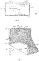
- Fig. 5 shows a device for determining a position of an ice hockey puck 520.
- the device can be used, for example, to determine whether the puck 520 is located in a goal 500, ie has crossed a goal line 550.
- the device comprises an excitation module 511 which is set up to generate an electromagnetic excitation field 530.
- the electromagnetic excitation field 530 is set up to excite the puck 320 to express (generate) the magnetic response field 540.
- the excitation module 511 can, for example, generate an electromagnetic excitation field in accordance with the principles described above.
- the excitation module 511 can generate an alternating magnetic field.
- the excitation module 511 can be arranged, for example, in or on a goal post or a crossbar 501 of the goal 500.
- the excitation module 511 can comprise one or more conductor loops, one or more coils or one or more coil systems which are arranged in or on the goal post or the crossbar 501 of the goal 500.
- the puck 520 which consists essentially of hard rubber and can have the shape of a disk, is set up to express or generate the magnetic response field 540 in response to the electromagnetic excitation field 530.
- the puck 520 can have, for example, one or more coils (not shown) or also one or more coil systems (not shown).
- the coil or the coil systems can be designed or set up in accordance with the principles described above.
- the device further comprises a measuring module which is set up to determine a plurality of measured values for the magnetic response field 540 by measuring the magnetic response field 540 at a plurality of predetermined measuring positions.
- the measuring module has a plurality of measuring sub-modules 512-1, 512-2, 512-3, which are arranged at the plurality of predetermined measuring positions.
- the measuring submodules 512-1, 512-2, 512-3 can be receiving antennas, for example, which measure the magnetic response field 540.
- the plurality of measuring positions can be arranged along the goal post or the crossbar 501 of the goal 500.
- several receiving antennas can be arranged in or on the goal post or the crossbar 501 of the goal 500.
- the measuring sub-modules 512-1, 512-2, 512-3 can be located below the gate 500 (for example in or below the ice surface).
- the number of receiving antennas does not depend on the in Fig. 5 three antennas shown is limited. Rather, any number of antennas (ie measurement sub-modules) can be used.
- the number of receiving antennas ie the measuring sub-modules can be selected based on a desired dimension or a desired accuracy of the position of the puck 520 to be determined.
- the goal post or the crossbar 501 of the goal 500 can consist at least partially of suitable materials which allow at least partial penetration by a magnetic field.
- the device also includes an evaluation module 513 which is set up to determine the position of the puck 520 based on a comparison of the plurality of measured values with reference measured values. A position of the movable object 520 is assigned to each of the reference measured values. The reference measured values are each determined by a simulation.
- the evaluation module 513 can be arranged, for example, in or on the goal post or the crossbar 501 of the goal 500 and forward the result of the position determination, for example by means of radio technology, to another entity. Alternatively, the evaluation module 513 can also be arranged outside the goal or ice hockey rink.
- the plurality of measured values can be transmitted from the measuring module to the evaluation module, for example via radio technology, and evaluated there.
- the device can enable the puck 520 to be located in real time. Due to the determination of the reference measurement values by means of a simulation, both the expenditure of time and the complexity for generating the reference measurement values can be reduced. Complex measurements to determine the reference measured values can be avoided.
- the position of the puck 520 that has just been determined can now be compared with a position of the goal line 550, for example.
- the puck 520 as well as the device for determining a position of the puck are in connection with one or more further exemplary embodiments (e.g. Figs. 1 and 3 ) described.
- the puck 520 as well as the device for determining a position of the puck can comprise one or more optional features according to one or more of the further exemplary embodiments.
- the position of one or more ice hockey players or one or more pieces of equipment for one or more ice hockey players can also be determined according to the principles set out above.
- the ice hockey player (s) or the equipment item (s) can be equipped with a component (element, device) which can express or generate a magnetic response field as a reaction to an electromagnetic excitation field.
- a component element, device
- one or more coils or one or more coil systems can be attached to a body of an ice hockey player or to an item of equipment of an ice hockey player. In this way, for example, a goal area away from an ice hockey player can also be determined.
- determining whether the puck 520 is in the goal 500 is only one example of determining a passage of a moving object through a plane of interest.
- the position of a movable object can be determined and compared with the position of a plane of interest in accordance with the above-mentioned principles.
- the methods described are not limited to use in ice hockey.
- the position of any athlete, any sports device or any piece of equipment can be determined.
- the positions of one or more players or one or more items of equipment can also be determined in accordance with the principles set out above. This can be a Support the referee or a game director in directing the game.
- a referee can decide whether a goal has been scored or not, or when deciding whether a player is illegally in a certain area of a playing field (e.g. offside in football or ice hockey), get supported.
- a certain area of a playing field e.g. offside in football or ice hockey
- the position determination according to the principles set out above can also be used, for example, in the generation of virtual realities in order to record a position, an orientation or a movement of a user in the real environment and to display this in the representation of the virtual reality consider.
- a position, an orientation or a movement of an object held or carried by a user can also be recorded and taken into account in the representation of the virtual reality.
- the position determination according to the principles set out above can in principle be used to determine a position of an object in any application scenario.
- embodiments of the invention or aspects thereof can be implemented in hardware or in software.
- the implementation can be carried out using a digital storage medium such as a floppy disk, a DVD, a Blu-Ray disk, a CD, a ROM, a PROM, an EPROM, an EEPROM or a FLASH memory, a hard disk or some other magnetic memory or optical memory can be carried out, on which electronically readable control signals are stored, which can interact or cooperate with a programmable hardware component in such a way that the respective method is carried out.
- a programmable hardware component can be formed by a processor, a CPU, a GPU, a computer, a computer system, an ASIC, an IC, a SoC, a programmable logic element or an FPGA.
- the digital storage medium can therefore be machine-readable or computer-readable.
- Some exemplary embodiments thus include a data carrier that has electronically readable control signals that are capable of interacting with a programmable computer system or a programmable hardware component in such a way that one of the methods described herein is carried out.
- One embodiment is thus a data carrier (or a digital storage medium or a computer-readable medium) on which the program for performing one of the methods described herein is recorded.
- embodiments of the present invention or aspects thereof can be implemented as a program, firmware, computer program or computer program product with a program code or as data, wherein the program code or the data is or are effective to carry out one of the methods or aspects thereof if the Program runs on a processor or a programmable hardware component.
- the program code or the data can, for example, also be stored on a machine-readable carrier or data carrier.
- the program code or the data can be present as source code, machine code or bytecode, as well as other intermediate code, among other things.
- a further exemplary embodiment is furthermore a data stream, a signal sequence or a sequence of signals which represents or represents the program for performing one of the methods described herein or aspects thereof.
- the data stream, the signal sequence or the sequence of signals can, for example, be configured to be transferred via a data communication connection, for example via the Internet or another network.
- Embodiments are thus also data-representing signal sequences which are suitable for transmission over a network or a data communication connection, the data representing the program.
- a program can implement one of the methods or aspects thereof during its execution, for example, by reading out memory locations or writing data or several data into them, whereby switching operations or other operations in transistor structures, in amplifier structures or in other electrical, optical, magnetic or components that work according to another functional principle.
- a program can therefore acquire, determine or measure quantities, values, measured quantities and other information by reading out one or more memory locations, and by writing to one or more memory locations it can cause, initiate or carry out an action and control other devices, machines and components .
Landscapes
- Physics & Mathematics (AREA)
- General Physics & Mathematics (AREA)
- Engineering & Computer Science (AREA)
- Radar, Positioning & Navigation (AREA)
- Remote Sensing (AREA)
- Measurement Of Length, Angles, Or The Like Using Electric Or Magnetic Means (AREA)
Claims (20)
- Procédé (100) pour déterminer une position d'un objet mobile dans l'espace pour localiser cet objet, comprenant le fait de :générer (102) un champ électromagnétique excitateur, le champ électromagnétique excitateur étant configuré pour exciter l'objet mobile afin de développer un champ de réponse magnétique ; etdéterminer (104) une pluralité de valeurs mesurées pour le champ de réponse magnétique en mesurant le champ de réponse magnétique à une pluralité de positions de mesure prédéterminées ; caractérisé par le fait dedéterminer (106) la position de l'objet mobile sur la base d'une comparaison de la pluralité de valeurs mesurées avec des valeurs mesurées de référence, les valeurs mesurées de référence étant chacune associée à une position de l'objet mobile, et les valeurs mesurées de référence chacune étant déterminée par une simulation.
- Procédé selon la revendication 1, dans lequel le fait de déterminer (106) la position de l'objet mobile comprend le fait de :
déterminer une similitude de l'une de la pluralité de valeurs mesurées avec l'une des valeurs mesurées de référence selon une métrique prédéterminée. - Procédé selon la revendication 2, dans lequel le fait de déterminer (106) la position de l'objet mobile comprend en outre le fait de :
déterminer, en tant que position de l'objet mobile, cette position de l'objet mobile associée à une valeur de référence, dont la valeur de référence, selon la métrique, a une plus grande similitude avec la pluralité de valeurs mesurées. - Procédé selon la revendication 2, dans lequel le fait de déterminer (106) la position de l'objet mobile comprend en outre le fait de :déterminer un nombre de valeurs de référence qui, selon la métrique, ont une plus grande similitude avec la pluralité de valeurs mesurées ; etdéterminer une valeur moyenne pondérée des positions de l'objet mobile associées au nombre de valeurs de référence en tant que la position de l'objet mobile.
- Procédé selon la revendication 4, dans lequel une pondération d'une position de l'objet mobile qui est associée à l'une du nombre de valeurs de référence est basée sur la similitude de l'une du nombre de valeurs de référence à la pluralité de valeurs mesurées.
- Procédé selon l'une des revendications précédentes, dans lequel le fait de déterminer la position (106) de l'objet mobile comprend en outre le fait de :
filtrer un candidat pour la position de l'objet mobile en utilisant un filtre de Kalman, le filtre de Kalman étant basé sur un modèle de mouvement pour l'objet mobile. - Procédé selon la revendication 6, dans lequel le fait de filtrer le candidat pour la position de l'objet mobile comprend le fait de :déterminer, en utilisant le modèle de mouvement, une position prédite de l'objet mobile sur la base des positions précédemment déterminées de l'objet mobile ; etcomparer la position prédite de l'objet mobile avec le candidat pour la position de l'objet mobile.
- Procédé selon la revendication 7, dans lequel le fait de filtrer le candidat pour la position de l'objet mobile comprend en outre le fait de :
éliminer le candidat pour la position de l'objet mobile si une différence entre la position prédite de l'objet mobile et le candidat pour la position de l'objet mobile est plus grande qu'un seuil. - Procédé selon l'une des revendications précédentes, dans lequel les valeurs mesurées de référence sont chacune associée à une orientation de l'objet mobile.
- Procédé selon l'une des revendications 1 à 8, dans lequel le champ de réponse magnétique est généré par trois bobines mutuellement orthogonales, et dans lequel les trois bobines sont configurées pour générer essentiellement les mêmes champs partiels de réponse magnétiques avec une orientation identique par rapport au champ électromagnétique excitateur.
- Procédé selon l'une des revendications 1 à 8, dans lequel le champ de réponse magnétique est généré par trois bobines mutuellement orthogonales, et dans lequel les trois bobines sont configurées pour générer des champs partiels de réponse magnétiques qui peuvent être distingués les uns des autres avec une orientation identique par rapport au champ électromagnétique excitateur.
- Procédé selon la revendication 11, dans lequel les trois bobines ont des fréquences de résonance différentes et/ou les champs partiels de réponse magnétiques respectifs des trois bobines sont modulés avec des séquences de codes différentes.
- Procédé selon l'une des revendications précédentes, dans lequel le fait de déterminer (104) la pluralité de valeurs mesurées pour le champ de réponse magnétique comprend le fait de :
normaliser la valeur mesurée déterminée pour l'une de la pluralité de positions de mesure prédéterminées sur la base de la somme des valeurs mesurées déterminées pour l'ensemble de la pluralité de positions de mesure prédéterminées. - Procédé selon la revendication 13, dans lequel la pluralité de positions de mesure prédéterminées est située à l'extérieur d'un plan dans lequel la génération du champ électromagnétique excitateur a lieu.
- Procédé selon l'une des revendications précédentes, dans lequel l'une des valeurs mesurées de référence est déterminée par la simulation sur la base d'une géométrie d'un système d'excitateur qui est utilisé pour générer le champ électromagnétique excitateur, d'une géométrie d'un système de réponse qui est utilisé pour émettre le champ de réponse magnétique, d'une géométrie d'un système de mesure qui est utilisé pour mesurer le champ de réponse magnétique, et d'une impédance du système de réponse.
- Procédé selon l'une des revendications précédentes, dans lequel le procédé comprend en outre le fait de :déterminer sur la base d'un balayage de fréquence du champ électromagnétique excitateur que l'objet mobile n'est pas situé dans un rayon prédéterminé autour d'un emplacement de génération du champ électromagnétique excitateur ;déterminer une pluralité de valeurs mesurées auxiliaires à la pluralité de positions de mesure prédéterminées, la pluralité de valeurs mesurées auxiliaires représentant un champ de réponse magnétique d'un objet interférant à la pluralité de positions de mesure prédéterminées ;estimer une position de l'objet interférant sur la base d'une comparaison de la pluralité de valeurs mesurées auxiliaires avec les valeurs mesurées de référence ; etDéterminer, en tenant compte de l'objet interférant, une valeur mesurée de référence mise à jour pour une position qui est à une distance maximale prédéterminée de la position de l'objet interférant.
- Procédé selon l'une des revendications précédentes, dans lequel le procédé comprend en outre le fait de :déterminer une pluralité de deuxièmes valeurs mesurées à la pluralité de positions de mesure prédéterminées, la pluralité de deuxièmes valeurs mesurées représentant un deuxième champ de réponse magnétique d'un deuxième objet mobile à la pluralité de positions de mesure prédéterminées, et dans lequel une première fréquence de résonance d'un premier système de réponse de l'objet mobile, qui est utilisé pour émettre le champ de réponse magnétique, est différente d'une deuxième fréquence de résonance d'un deuxième système de réponse du deuxième objet mobile, qui est utilisé pour émettre le deuxième champ de réponse magnétique ; etdéterminer la position du deuxième objet mobile sur la base d'une comparaison de la pluralité de deuxièmes valeurs mesurées avec les valeurs mesurées de référence.
- Procédé selon l'une des revendications 1 à 16, dans lequel le procédé comprend en outre le fait de :déterminer une pluralité de deuxièmes valeurs mesurées à la pluralité de positions de mesure prédéterminées, la pluralité de deuxièmes valeurs mesurées représentant un deuxième champ de réponse magnétique d'un deuxième objet mobile à la pluralité de positions de mesure prédéterminées, et dans lequel le champ de réponse magnétique et le deuxième champ de réponse magnétique sont modulés avec des codes mutuellement orthogonaux ;déterminer la position du deuxième objet mobile sur la base d'une comparaison de la pluralité de deuxièmes valeurs mesurées avec les valeurs mesurées de référence.
- Dispositif (310) pour déterminer une position d'un objet mobile (320) dans l'espace pour localiser cet objet, comprenant :un module excitateur (311) qui est configuré pour générer un champ électromagnétique excitateur (330), dans lequel le champ électromagnétique excitateur (330) est configuré pour exciter l'objet mobile (320) afin de développer un champ de réponse magnétique (340) ; etun module de mesure (312) qui est configuré pour déterminer une pluralité de valeurs mesurées pour le champ de réponse magnétique (340) en mesurant le champ de réponse magnétique (340) à une pluralité de positions de mesure prédéterminées ; caractérisé parun module d'évaluation (313) qui est configuré pour déterminer la position de l'objet mobile (320) sur la base d'une comparaison de la pluralité de valeurs mesurées avec des valeurs mesurées de référence, les valeurs mesurées de référence étant chacune associée à une position de l'objet mobile (320), et les valeurs mesurées de référence étant chacune déterminée par une simulation.
- Système (300) comprenant :au moins un objet mobile (340) qui est configuré pour développer un champ de réponse magnétique (340) en réponse à un champ électromagnétique excitateur (330) ; etun dispositif (310) pour déterminer une position d'un objet mobile selon la revendication 19.
Applications Claiming Priority (2)
| Application Number | Priority Date | Filing Date | Title |
|---|---|---|---|
| DE102016120250.9A DE102016120250A1 (de) | 2016-10-24 | 2016-10-24 | Verfahren und vorrichtung zum bestimmen einer position eines beweglichen objekts sowie system umfassend die vorrichtung |
| PCT/EP2017/071673 WO2018077513A1 (fr) | 2016-10-24 | 2017-08-29 | Procédé et dispositif pour déterminer une position d'un objet mobile ainsi que système comprenant le dispositif |
Publications (2)
| Publication Number | Publication Date |
|---|---|
| EP3529552A1 EP3529552A1 (fr) | 2019-08-28 |
| EP3529552B1 true EP3529552B1 (fr) | 2021-10-06 |
Family
ID=59895273
Family Applications (1)
| Application Number | Title | Priority Date | Filing Date |
|---|---|---|---|
| EP17768377.8A Active EP3529552B1 (fr) | 2016-10-24 | 2017-08-29 | Procédé et dispositif pour déterminer une position d'un objet mobile ainsi que système comprenant le dispositif |
Country Status (7)
| Country | Link |
|---|---|
| US (1) | US11268801B2 (fr) |
| EP (1) | EP3529552B1 (fr) |
| CA (1) | CA3041186C (fr) |
| DE (1) | DE102016120250A1 (fr) |
| DK (1) | DK3529552T3 (fr) |
| ES (1) | ES2902846T3 (fr) |
| WO (1) | WO2018077513A1 (fr) |
Families Citing this family (4)
| Publication number | Priority date | Publication date | Assignee | Title |
|---|---|---|---|---|
| EP3736756A1 (fr) | 2019-05-10 | 2020-11-11 | Fraunhofer-Gesellschaft zur Förderung der angewandten Forschung e.V. | Procédé pour systèmes logistiques intelligents |
| CN116163507B (zh) * | 2023-04-23 | 2023-07-07 | 四川蜀道建筑科技有限公司 | 一种用于自爬升起吊设备的控制系统 |
| DE102023136527A1 (de) * | 2023-12-22 | 2025-06-26 | Endress+Hauser Flowtec Ag | Verfahren zum Erzeugen von Referenzdaten zur Klassifizierung von leitfähigen Gegenständen mit einem Metalldetektor, Verfahren zur Klassifizierung von leitfähigen Gegenständen, Metalldetektor, Vorrichtung und Messgerät |
| US20250378569A1 (en) * | 2024-06-10 | 2025-12-11 | Qualcomm Incorporated | Determining positions of objects based on images and ground-plane models |
Family Cites Families (14)
| Publication number | Priority date | Publication date | Assignee | Title |
|---|---|---|---|---|
| IL126284A (en) * | 1998-09-17 | 2002-12-01 | Netmor Ltd | System and method for three dimensional positioning and tracking |
| US6789043B1 (en) * | 1998-09-23 | 2004-09-07 | The Johns Hopkins University | Magnetic sensor system for fast-response, high resolution, high accuracy, three-dimensional position measurements |
| JP4405924B2 (ja) | 2002-10-28 | 2010-01-27 | フラウンホーファー・ゲゼルシャフト・ツール・フェルデルング・デア・アンゲヴァンテン・フォルシュング・エー・ファウ | 少なくとも1つの移動対象物を連続的にリアルタイムで追跡するための方法、並びにそのための送信器と受信器 |
| EA012020B1 (ru) * | 2005-03-09 | 2009-06-30 | Гоалреф Апс | Устройство обнаружения для ворот для регистрации объекта, пересекающего плоскость ворот |
| US7795861B2 (en) * | 2006-05-02 | 2010-09-14 | Cairos Technologies Ag | Method and apparatus for controlling a movable object for localization within a positioning area |
| DE102006047376B3 (de) * | 2006-10-06 | 2008-04-10 | Cairos Technologies Ag | Konzept zur Torentscheidung mittels Magnetfeldern |
| WO2010009531A1 (fr) | 2008-07-23 | 2010-01-28 | Atreo Medical, Inc. | Dispositif d'assistance à la réanimation cardio-respiratoire permettant de mesurer les paramètres de compression durant la réanimation cardio-respiratoire |
| US8450997B2 (en) * | 2009-04-28 | 2013-05-28 | Brown University | Electromagnetic position and orientation sensing system |
| US9625247B2 (en) * | 2010-06-28 | 2017-04-18 | Disney Enterprises, Inc. | Systems and methods for position tracking using magnetoquasistatic fields |
| WO2013149649A2 (fr) * | 2012-04-02 | 2013-10-10 | Fraunhofer-Gesellschaft zur Förderung der angewandten Forschung e. V. | Système d'antenne et procédé pour déterminer un transit d'un objet en mouvement à travers une zone d'intérêt |
| ES2652213T3 (es) * | 2013-06-12 | 2018-02-01 | Fraunhofer-Gesellschaft zur Förderung der angewandten Forschung e.V. | Sistema de antenas y método para determinar el paso de un objeto desplazable a través de un plano de detección |
| DE102013214283A1 (de) * | 2013-07-22 | 2015-01-22 | Fraunhofer-Gesellschaft zur Förderung der angewandten Forschung e.V. | Vorrichtung und Verfahren zur Überwachung eines Zugriffs auf einen Lagerbereich einer Mehrzahl von Lagerbereichen für Waren |
| CN105222772B (zh) * | 2015-09-17 | 2018-03-16 | 泉州装备制造研究所 | 一种基于多源信息融合的高精度运动轨迹检测系统 |
| US10345118B2 (en) * | 2016-09-13 | 2019-07-09 | Intel Corporation | Methods and apparatus for high speed location determinations |
-
2016
- 2016-10-24 DE DE102016120250.9A patent/DE102016120250A1/de not_active Withdrawn
-
2017
- 2017-08-29 US US16/344,399 patent/US11268801B2/en not_active Expired - Fee Related
- 2017-08-29 EP EP17768377.8A patent/EP3529552B1/fr active Active
- 2017-08-29 WO PCT/EP2017/071673 patent/WO2018077513A1/fr not_active Ceased
- 2017-08-29 DK DK17768377.8T patent/DK3529552T3/da active
- 2017-08-29 ES ES17768377T patent/ES2902846T3/es active Active
- 2017-08-29 CA CA3041186A patent/CA3041186C/fr active Active
Also Published As
| Publication number | Publication date |
|---|---|
| US11268801B2 (en) | 2022-03-08 |
| ES2902846T3 (es) | 2022-03-30 |
| EP3529552A1 (fr) | 2019-08-28 |
| DK3529552T3 (da) | 2022-01-10 |
| CA3041186C (fr) | 2022-01-18 |
| DE102016120250A1 (de) | 2018-04-26 |
| CA3041186A1 (fr) | 2018-05-03 |
| US20200049479A1 (en) | 2020-02-13 |
| WO2018077513A1 (fr) | 2018-05-03 |
Similar Documents
| Publication | Publication Date | Title |
|---|---|---|
| EP3529552B1 (fr) | Procédé et dispositif pour déterminer une position d'un objet mobile ainsi que système comprenant le dispositif | |
| EP1984082B1 (fr) | Concept relatif à la détection d'un contact avec un article de jeu | |
| EP2427781B1 (fr) | Concept pour déterminer une valeur estimée représentative de l'emplacement d'un élément de réception | |
| EP2366121B1 (fr) | Système et procédé de reconnaissance de détention de balle à l'aide d'une génération de champ passif | |
| EP2923301B1 (fr) | Procédé et dispositif de reconstitution d'un mouvement d'un objet | |
| DE60111488T2 (de) | Golfspiel | |
| KR102897015B1 (ko) | 미리 결정된 오프라인 정보를 고려한 획득 스트로크 성능 메트릭을 볼 비행 데이터로부터 계산하기 위한 시스템 및 방법 | |
| EP3066655B1 (fr) | Appareil et procédé d'evaluation automatique du déroulement d'une session d'entraînement | |
| DE202006021074U1 (de) | Bestimmung von Eigendrehimpulsparametern von einem Sportball | |
| DE102015113809B4 (de) | Golfball, System und Verfahren zur Ortung eines Golfballs | |
| DE102005027668A1 (de) | Verfahren im Zusammenhang mit einem Armbandcomputer und ein Armbandcomputersystem | |
| EP1034818A1 (fr) | Dispositif de navigation pour le golf | |
| DE102008057705A1 (de) | Erfassen und Bereitstellen von Spielerinformationen mit spielerseitigem Sensor | |
| DE102007015493A1 (de) | Bewegungsbereich für einen mobilen Gegenstand und Auswertungsvorrichtung zum Feststellen einer Position eines mobilen Gegenstands | |
| WO2015011056A1 (fr) | Dispositif et procédé de surveillance d'un accès à une zone de stockage d'une pluralité de zones de stockage de marchandises | |
| DE19914486C1 (de) | Vorrichtung und Verfahren zur berührungslosen Geschwindigkeitsmessung auf Oberflächen | |
| DE112022007502T5 (de) | Positionsermittlungseinrichtung, positionsermittlungssystem, steuerschaltung, speichermedium und positionsermittlungsverfahren | |
| DE19742463A1 (de) | Meßwerte Kartierungsverfahren | |
| DE102017126981A1 (de) | System und verfahren zum bestimmen eines durchgangs eines beweglichen objekts durch einen interessierenden bereich einer überwachten ebene, sowie bewegliche objekte | |
| AT525417B1 (de) | Verfahren zur automatischen Berechnung von Ballsportstatistiken | |
| DE102008060049A1 (de) | Verfahren zur Bestimmung einer Kodierung für eine Flussmessung und Verfahren zur Flussmessung sowie entsprechend ausgestaltete Magnetresonanzanlage | |
| DE102023136527A1 (de) | Verfahren zum Erzeugen von Referenzdaten zur Klassifizierung von leitfähigen Gegenständen mit einem Metalldetektor, Verfahren zur Klassifizierung von leitfähigen Gegenständen, Metalldetektor, Vorrichtung und Messgerät | |
| DE102015003383A1 (de) | Schienbeinschoner mit intregriertem multimodalen Sensorsystem (ShinGuardEA4ST - Shin Guard Embedded Analytics for Soccer Talents) | |
| DE102017205271A1 (de) | Verfahren und System zur Lokalisierung eines mobilen Geräts und mobiles Gerät | |
| DE1181760B (de) | Radargeraet mit mehreren unterschiedlich geneigten, faecherfoermigen Strahlungscharak-teristiken und Mitteln zur Hoehenberechnung |
Legal Events
| Date | Code | Title | Description |
|---|---|---|---|
| STAA | Information on the status of an ep patent application or granted ep patent |
Free format text: STATUS: UNKNOWN |
|
| STAA | Information on the status of an ep patent application or granted ep patent |
Free format text: STATUS: THE INTERNATIONAL PUBLICATION HAS BEEN MADE |
|
| PUAI | Public reference made under article 153(3) epc to a published international application that has entered the european phase |
Free format text: ORIGINAL CODE: 0009012 |
|
| STAA | Information on the status of an ep patent application or granted ep patent |
Free format text: STATUS: REQUEST FOR EXAMINATION WAS MADE |
|
| 17P | Request for examination filed |
Effective date: 20190524 |
|
| AK | Designated contracting states |
Kind code of ref document: A1 Designated state(s): AL AT BE BG CH CY CZ DE DK EE ES FI FR GB GR HR HU IE IS IT LI LT LU LV MC MK MT NL NO PL PT RO RS SE SI SK SM TR |
|
| AX | Request for extension of the european patent |
Extension state: BA ME |
|
| DAV | Request for validation of the european patent (deleted) | ||
| DAX | Request for extension of the european patent (deleted) | ||
| REG | Reference to a national code |
Ref country code: DE Ref legal event code: R079 Ref document number: 502017011686 Country of ref document: DE Free format text: PREVIOUS MAIN CLASS: G01B0011000000 Ipc: G01B0007000000 |
|
| RIC1 | Information provided on ipc code assigned before grant |
Ipc: G01B 7/00 20060101AFI20210510BHEP |
|
| GRAP | Despatch of communication of intention to grant a patent |
Free format text: ORIGINAL CODE: EPIDOSNIGR1 |
|
| STAA | Information on the status of an ep patent application or granted ep patent |
Free format text: STATUS: GRANT OF PATENT IS INTENDED |
|
| INTG | Intention to grant announced |
Effective date: 20210621 |
|
| GRAS | Grant fee paid |
Free format text: ORIGINAL CODE: EPIDOSNIGR3 |
|
| GRAA | (expected) grant |
Free format text: ORIGINAL CODE: 0009210 |
|
| STAA | Information on the status of an ep patent application or granted ep patent |
Free format text: STATUS: THE PATENT HAS BEEN GRANTED |
|
| AK | Designated contracting states |
Kind code of ref document: B1 Designated state(s): AL AT BE BG CH CY CZ DE DK EE ES FI FR GB GR HR HU IE IS IT LI LT LU LV MC MK MT NL NO PL PT RO RS SE SI SK SM TR |
|
| REG | Reference to a national code |
Ref country code: GB Ref legal event code: FG4D Free format text: NOT ENGLISH |
|
| REG | Reference to a national code |
Ref country code: CH Ref legal event code: EP Ref country code: AT Ref legal event code: REF Ref document number: 1436576 Country of ref document: AT Kind code of ref document: T Effective date: 20211015 |
|
| REG | Reference to a national code |
Ref country code: DE Ref legal event code: R096 Ref document number: 502017011686 Country of ref document: DE |
|
| REG | Reference to a national code |
Ref country code: IE Ref legal event code: FG4D Free format text: LANGUAGE OF EP DOCUMENT: GERMAN |
|
| REG | Reference to a national code |
Ref country code: DK Ref legal event code: T3 Effective date: 20220107 |
|
| REG | Reference to a national code |
Ref country code: LT Ref legal event code: MG9D |
|
| REG | Reference to a national code |
Ref country code: NL Ref legal event code: MP Effective date: 20211006 |
|
| REG | Reference to a national code |
Ref country code: ES Ref legal event code: FG2A Ref document number: 2902846 Country of ref document: ES Kind code of ref document: T3 Effective date: 20220330 |
|
| RAP4 | Party data changed (patent owner data changed or rights of a patent transferred) |
Owner name: FRAUNHOFER-GESELLSCHAFT ZUR FOERDERUNG DER ANGEWANDTEN FORSCHUNG E.V. |
|
| PG25 | Lapsed in a contracting state [announced via postgrant information from national office to epo] |
Ref country code: RS Free format text: LAPSE BECAUSE OF FAILURE TO SUBMIT A TRANSLATION OF THE DESCRIPTION OR TO PAY THE FEE WITHIN THE PRESCRIBED TIME-LIMIT Effective date: 20211006 Ref country code: LT Free format text: LAPSE BECAUSE OF FAILURE TO SUBMIT A TRANSLATION OF THE DESCRIPTION OR TO PAY THE FEE WITHIN THE PRESCRIBED TIME-LIMIT Effective date: 20211006 Ref country code: FI Free format text: LAPSE BECAUSE OF FAILURE TO SUBMIT A TRANSLATION OF THE DESCRIPTION OR TO PAY THE FEE WITHIN THE PRESCRIBED TIME-LIMIT Effective date: 20211006 Ref country code: BG Free format text: LAPSE BECAUSE OF FAILURE TO SUBMIT A TRANSLATION OF THE DESCRIPTION OR TO PAY THE FEE WITHIN THE PRESCRIBED TIME-LIMIT Effective date: 20220106 |
|
| PG25 | Lapsed in a contracting state [announced via postgrant information from national office to epo] |
Ref country code: IS Free format text: LAPSE BECAUSE OF FAILURE TO SUBMIT A TRANSLATION OF THE DESCRIPTION OR TO PAY THE FEE WITHIN THE PRESCRIBED TIME-LIMIT Effective date: 20220206 Ref country code: SE Free format text: LAPSE BECAUSE OF FAILURE TO SUBMIT A TRANSLATION OF THE DESCRIPTION OR TO PAY THE FEE WITHIN THE PRESCRIBED TIME-LIMIT Effective date: 20211006 Ref country code: PT Free format text: LAPSE BECAUSE OF FAILURE TO SUBMIT A TRANSLATION OF THE DESCRIPTION OR TO PAY THE FEE WITHIN THE PRESCRIBED TIME-LIMIT Effective date: 20220207 Ref country code: PL Free format text: LAPSE BECAUSE OF FAILURE TO SUBMIT A TRANSLATION OF THE DESCRIPTION OR TO PAY THE FEE WITHIN THE PRESCRIBED TIME-LIMIT Effective date: 20211006 Ref country code: NO Free format text: LAPSE BECAUSE OF FAILURE TO SUBMIT A TRANSLATION OF THE DESCRIPTION OR TO PAY THE FEE WITHIN THE PRESCRIBED TIME-LIMIT Effective date: 20220106 Ref country code: NL Free format text: LAPSE BECAUSE OF FAILURE TO SUBMIT A TRANSLATION OF THE DESCRIPTION OR TO PAY THE FEE WITHIN THE PRESCRIBED TIME-LIMIT Effective date: 20211006 Ref country code: LV Free format text: LAPSE BECAUSE OF FAILURE TO SUBMIT A TRANSLATION OF THE DESCRIPTION OR TO PAY THE FEE WITHIN THE PRESCRIBED TIME-LIMIT Effective date: 20211006 Ref country code: HR Free format text: LAPSE BECAUSE OF FAILURE TO SUBMIT A TRANSLATION OF THE DESCRIPTION OR TO PAY THE FEE WITHIN THE PRESCRIBED TIME-LIMIT Effective date: 20211006 Ref country code: GR Free format text: LAPSE BECAUSE OF FAILURE TO SUBMIT A TRANSLATION OF THE DESCRIPTION OR TO PAY THE FEE WITHIN THE PRESCRIBED TIME-LIMIT Effective date: 20220107 |
|
| REG | Reference to a national code |
Ref country code: DE Ref legal event code: R097 Ref document number: 502017011686 Country of ref document: DE |
|
| PG25 | Lapsed in a contracting state [announced via postgrant information from national office to epo] |
Ref country code: SM Free format text: LAPSE BECAUSE OF FAILURE TO SUBMIT A TRANSLATION OF THE DESCRIPTION OR TO PAY THE FEE WITHIN THE PRESCRIBED TIME-LIMIT Effective date: 20211006 Ref country code: SK Free format text: LAPSE BECAUSE OF FAILURE TO SUBMIT A TRANSLATION OF THE DESCRIPTION OR TO PAY THE FEE WITHIN THE PRESCRIBED TIME-LIMIT Effective date: 20211006 Ref country code: RO Free format text: LAPSE BECAUSE OF FAILURE TO SUBMIT A TRANSLATION OF THE DESCRIPTION OR TO PAY THE FEE WITHIN THE PRESCRIBED TIME-LIMIT Effective date: 20211006 Ref country code: EE Free format text: LAPSE BECAUSE OF FAILURE TO SUBMIT A TRANSLATION OF THE DESCRIPTION OR TO PAY THE FEE WITHIN THE PRESCRIBED TIME-LIMIT Effective date: 20211006 Ref country code: CZ Free format text: LAPSE BECAUSE OF FAILURE TO SUBMIT A TRANSLATION OF THE DESCRIPTION OR TO PAY THE FEE WITHIN THE PRESCRIBED TIME-LIMIT Effective date: 20211006 |
|
| PLBE | No opposition filed within time limit |
Free format text: ORIGINAL CODE: 0009261 |
|
| STAA | Information on the status of an ep patent application or granted ep patent |
Free format text: STATUS: NO OPPOSITION FILED WITHIN TIME LIMIT |
|
| 26N | No opposition filed |
Effective date: 20220707 |
|
| PG25 | Lapsed in a contracting state [announced via postgrant information from national office to epo] |
Ref country code: AL Free format text: LAPSE BECAUSE OF FAILURE TO SUBMIT A TRANSLATION OF THE DESCRIPTION OR TO PAY THE FEE WITHIN THE PRESCRIBED TIME-LIMIT Effective date: 20211006 |
|
| PG25 | Lapsed in a contracting state [announced via postgrant information from national office to epo] |
Ref country code: SI Free format text: LAPSE BECAUSE OF FAILURE TO SUBMIT A TRANSLATION OF THE DESCRIPTION OR TO PAY THE FEE WITHIN THE PRESCRIBED TIME-LIMIT Effective date: 20211006 |
|
| PG25 | Lapsed in a contracting state [announced via postgrant information from national office to epo] |
Ref country code: MC Free format text: LAPSE BECAUSE OF FAILURE TO SUBMIT A TRANSLATION OF THE DESCRIPTION OR TO PAY THE FEE WITHIN THE PRESCRIBED TIME-LIMIT Effective date: 20211006 |
|
| REG | Reference to a national code |
Ref country code: CH Ref legal event code: PL |
|
| PG25 | Lapsed in a contracting state [announced via postgrant information from national office to epo] |
Ref country code: LU Free format text: LAPSE BECAUSE OF NON-PAYMENT OF DUE FEES Effective date: 20220829 Ref country code: LI Free format text: LAPSE BECAUSE OF NON-PAYMENT OF DUE FEES Effective date: 20220831 Ref country code: CH Free format text: LAPSE BECAUSE OF NON-PAYMENT OF DUE FEES Effective date: 20220831 |
|
| REG | Reference to a national code |
Ref country code: BE Ref legal event code: MM Effective date: 20220831 |
|
| P01 | Opt-out of the competence of the unified patent court (upc) registered |
Effective date: 20230524 |
|
| PG25 | Lapsed in a contracting state [announced via postgrant information from national office to epo] |
Ref country code: IE Free format text: LAPSE BECAUSE OF NON-PAYMENT OF DUE FEES Effective date: 20220829 |
|
| PG25 | Lapsed in a contracting state [announced via postgrant information from national office to epo] |
Ref country code: BE Free format text: LAPSE BECAUSE OF NON-PAYMENT OF DUE FEES Effective date: 20220831 |
|
| REG | Reference to a national code |
Ref country code: AT Ref legal event code: MM01 Ref document number: 1436576 Country of ref document: AT Kind code of ref document: T Effective date: 20220829 |
|
| PG25 | Lapsed in a contracting state [announced via postgrant information from national office to epo] |
Ref country code: AT Free format text: LAPSE BECAUSE OF NON-PAYMENT OF DUE FEES Effective date: 20220829 |
|
| PG25 | Lapsed in a contracting state [announced via postgrant information from national office to epo] |
Ref country code: HU Free format text: LAPSE BECAUSE OF FAILURE TO SUBMIT A TRANSLATION OF THE DESCRIPTION OR TO PAY THE FEE WITHIN THE PRESCRIBED TIME-LIMIT; INVALID AB INITIO Effective date: 20170829 |
|
| PG25 | Lapsed in a contracting state [announced via postgrant information from national office to epo] |
Ref country code: CY Free format text: LAPSE BECAUSE OF FAILURE TO SUBMIT A TRANSLATION OF THE DESCRIPTION OR TO PAY THE FEE WITHIN THE PRESCRIBED TIME-LIMIT Effective date: 20211006 |
|
| PG25 | Lapsed in a contracting state [announced via postgrant information from national office to epo] |
Ref country code: MK Free format text: LAPSE BECAUSE OF FAILURE TO SUBMIT A TRANSLATION OF THE DESCRIPTION OR TO PAY THE FEE WITHIN THE PRESCRIBED TIME-LIMIT Effective date: 20211006 |
|
| PG25 | Lapsed in a contracting state [announced via postgrant information from national office to epo] |
Ref country code: MT Free format text: LAPSE BECAUSE OF FAILURE TO SUBMIT A TRANSLATION OF THE DESCRIPTION OR TO PAY THE FEE WITHIN THE PRESCRIBED TIME-LIMIT Effective date: 20211006 |
|
| PGFP | Annual fee paid to national office [announced via postgrant information from national office to epo] |
Ref country code: DE Payment date: 20240819 Year of fee payment: 8 |
|
| PGFP | Annual fee paid to national office [announced via postgrant information from national office to epo] |
Ref country code: DK Payment date: 20240822 Year of fee payment: 8 |
|
| PGFP | Annual fee paid to national office [announced via postgrant information from national office to epo] |
Ref country code: GB Payment date: 20240822 Year of fee payment: 8 |
|
| PGFP | Annual fee paid to national office [announced via postgrant information from national office to epo] |
Ref country code: FR Payment date: 20240814 Year of fee payment: 8 |
|
| PGFP | Annual fee paid to national office [announced via postgrant information from national office to epo] |
Ref country code: ES Payment date: 20240918 Year of fee payment: 8 |
|
| PGFP | Annual fee paid to national office [announced via postgrant information from national office to epo] |
Ref country code: IT Payment date: 20240830 Year of fee payment: 8 |
|
| PG25 | Lapsed in a contracting state [announced via postgrant information from national office to epo] |
Ref country code: TR Free format text: LAPSE BECAUSE OF FAILURE TO SUBMIT A TRANSLATION OF THE DESCRIPTION OR TO PAY THE FEE WITHIN THE PRESCRIBED TIME-LIMIT Effective date: 20211006 |
|
| REG | Reference to a national code |
Ref country code: DE Ref legal event code: R119 Ref document number: 502017011686 Country of ref document: DE |
|
| REG | Reference to a national code |
Ref country code: DK Ref legal event code: EBP Effective date: 20250831 |