EP3529098B1 - Vehicle having non-axial drive and stabilization system - Google Patents
Vehicle having non-axial drive and stabilization system Download PDFInfo
- Publication number
- EP3529098B1 EP3529098B1 EP16790806.0A EP16790806A EP3529098B1 EP 3529098 B1 EP3529098 B1 EP 3529098B1 EP 16790806 A EP16790806 A EP 16790806A EP 3529098 B1 EP3529098 B1 EP 3529098B1
- Authority
- EP
- European Patent Office
- Prior art keywords
- chassis
- wheel
- wheeled vehicle
- counterweight
- gear
- Prior art date
- Legal status (The legal status is an assumption and is not a legal conclusion. Google has not performed a legal analysis and makes no representation as to the accuracy of the status listed.)
- Active
Links
Images







Classifications
-
- B—PERFORMING OPERATIONS; TRANSPORTING
- B62—LAND VEHICLES FOR TRAVELLING OTHERWISE THAN ON RAILS
- B62D—MOTOR VEHICLES; TRAILERS
- B62D37/00—Stabilising vehicle bodies without controlling suspension arrangements
- B62D37/04—Stabilising vehicle bodies without controlling suspension arrangements by means of movable masses
-
- B—PERFORMING OPERATIONS; TRANSPORTING
- B60—VEHICLES IN GENERAL
- B60K—ARRANGEMENT OR MOUNTING OF PROPULSION UNITS OR OF TRANSMISSIONS IN VEHICLES; ARRANGEMENT OR MOUNTING OF PLURAL DIVERSE PRIME-MOVERS IN VEHICLES; AUXILIARY DRIVES FOR VEHICLES; INSTRUMENTATION OR DASHBOARDS FOR VEHICLES; ARRANGEMENTS IN CONNECTION WITH COOLING, AIR INTAKE, GAS EXHAUST OR FUEL SUPPLY OF PROPULSION UNITS IN VEHICLES
- B60K1/00—Arrangement or mounting of electrical propulsion units
- B60K1/02—Arrangement or mounting of electrical propulsion units comprising more than one electric motor
-
- B—PERFORMING OPERATIONS; TRANSPORTING
- B60—VEHICLES IN GENERAL
- B60K—ARRANGEMENT OR MOUNTING OF PROPULSION UNITS OR OF TRANSMISSIONS IN VEHICLES; ARRANGEMENT OR MOUNTING OF PLURAL DIVERSE PRIME-MOVERS IN VEHICLES; AUXILIARY DRIVES FOR VEHICLES; INSTRUMENTATION OR DASHBOARDS FOR VEHICLES; ARRANGEMENTS IN CONNECTION WITH COOLING, AIR INTAKE, GAS EXHAUST OR FUEL SUPPLY OF PROPULSION UNITS IN VEHICLES
- B60K7/00—Disposition of motor in, or adjacent to, traction wheel
- B60K7/0007—Disposition of motor in, or adjacent to, traction wheel the motor being electric
-
- B—PERFORMING OPERATIONS; TRANSPORTING
- B62—LAND VEHICLES FOR TRAVELLING OTHERWISE THAN ON RAILS
- B62K—CYCLES; CYCLE FRAMES; CYCLE STEERING DEVICES; RIDER-OPERATED TERMINAL CONTROLS SPECIALLY ADAPTED FOR CYCLES; CYCLE AXLE SUSPENSIONS; CYCLE SIDECARS, FORECARS, OR THE LIKE
- B62K11/00—Motorcycles, engine-assisted cycles or motor scooters with one or two wheels
- B62K11/007—Automatic balancing machines with single main ground engaging wheel or coaxial wheels supporting a rider
-
- B—PERFORMING OPERATIONS; TRANSPORTING
- B62—LAND VEHICLES FOR TRAVELLING OTHERWISE THAN ON RAILS
- B62K—CYCLES; CYCLE FRAMES; CYCLE STEERING DEVICES; RIDER-OPERATED TERMINAL CONTROLS SPECIALLY ADAPTED FOR CYCLES; CYCLE AXLE SUSPENSIONS; CYCLE SIDECARS, FORECARS, OR THE LIKE
- B62K7/00—Freight- or passenger-carrying cycles
- B62K7/02—Frames
- B62K7/04—Frames having a carrying platform
-
- B—PERFORMING OPERATIONS; TRANSPORTING
- B62—LAND VEHICLES FOR TRAVELLING OTHERWISE THAN ON RAILS
- B62M—RIDER PROPULSION OF WHEELED VEHICLES OR SLEDGES; POWERED PROPULSION OF SLEDGES OR SINGLE-TRACK CYCLES; TRANSMISSIONS SPECIALLY ADAPTED FOR SUCH VEHICLES
- B62M11/00—Transmissions characterised by the use of interengaging toothed wheels or frictionally-engaging wheels
-
- B—PERFORMING OPERATIONS; TRANSPORTING
- B62—LAND VEHICLES FOR TRAVELLING OTHERWISE THAN ON RAILS
- B62M—RIDER PROPULSION OF WHEELED VEHICLES OR SLEDGES; POWERED PROPULSION OF SLEDGES OR SINGLE-TRACK CYCLES; TRANSMISSIONS SPECIALLY ADAPTED FOR SUCH VEHICLES
- B62M7/00—Motorcycles characterised by position of motor or engine
- B62M7/12—Motorcycles characterised by position of motor or engine with the engine beside or within the driven wheel
-
- F—MECHANICAL ENGINEERING; LIGHTING; HEATING; WEAPONS; BLASTING
- F16—ENGINEERING ELEMENTS AND UNITS; GENERAL MEASURES FOR PRODUCING AND MAINTAINING EFFECTIVE FUNCTIONING OF MACHINES OR INSTALLATIONS; THERMAL INSULATION IN GENERAL
- F16H—GEARING
- F16H1/00—Toothed gearings for conveying rotary motion
- F16H1/02—Toothed gearings for conveying rotary motion without gears having orbital motion
- F16H1/04—Toothed gearings for conveying rotary motion without gears having orbital motion involving only two intermeshing members
-
- F—MECHANICAL ENGINEERING; LIGHTING; HEATING; WEAPONS; BLASTING
- F16—ENGINEERING ELEMENTS AND UNITS; GENERAL MEASURES FOR PRODUCING AND MAINTAINING EFFECTIVE FUNCTIONING OF MACHINES OR INSTALLATIONS; THERMAL INSULATION IN GENERAL
- F16H—GEARING
- F16H1/00—Toothed gearings for conveying rotary motion
- F16H1/02—Toothed gearings for conveying rotary motion without gears having orbital motion
- F16H1/20—Toothed gearings for conveying rotary motion without gears having orbital motion involving more than two intermeshing members
-
- G—PHYSICS
- G01—MEASURING; TESTING
- G01C—MEASURING DISTANCES, LEVELS OR BEARINGS; SURVEYING; NAVIGATION; GYROSCOPIC INSTRUMENTS; PHOTOGRAMMETRY OR VIDEOGRAMMETRY
- G01C9/00—Measuring inclination, e.g. by clinometers, by levels
-
- B—PERFORMING OPERATIONS; TRANSPORTING
- B60—VEHICLES IN GENERAL
- B60K—ARRANGEMENT OR MOUNTING OF PROPULSION UNITS OR OF TRANSMISSIONS IN VEHICLES; ARRANGEMENT OR MOUNTING OF PLURAL DIVERSE PRIME-MOVERS IN VEHICLES; AUXILIARY DRIVES FOR VEHICLES; INSTRUMENTATION OR DASHBOARDS FOR VEHICLES; ARRANGEMENTS IN CONNECTION WITH COOLING, AIR INTAKE, GAS EXHAUST OR FUEL SUPPLY OF PROPULSION UNITS IN VEHICLES
- B60K1/00—Arrangement or mounting of electrical propulsion units
- B60K1/04—Arrangement or mounting of electrical propulsion units of the electric storage means for propulsion
-
- B—PERFORMING OPERATIONS; TRANSPORTING
- B60—VEHICLES IN GENERAL
- B60K—ARRANGEMENT OR MOUNTING OF PROPULSION UNITS OR OF TRANSMISSIONS IN VEHICLES; ARRANGEMENT OR MOUNTING OF PLURAL DIVERSE PRIME-MOVERS IN VEHICLES; AUXILIARY DRIVES FOR VEHICLES; INSTRUMENTATION OR DASHBOARDS FOR VEHICLES; ARRANGEMENTS IN CONNECTION WITH COOLING, AIR INTAKE, GAS EXHAUST OR FUEL SUPPLY OF PROPULSION UNITS IN VEHICLES
- B60K7/00—Disposition of motor in, or adjacent to, traction wheel
- B60K2007/0061—Disposition of motor in, or adjacent to, traction wheel the motor axle being parallel to the wheel axle
-
- B—PERFORMING OPERATIONS; TRANSPORTING
- B60—VEHICLES IN GENERAL
- B60K—ARRANGEMENT OR MOUNTING OF PROPULSION UNITS OR OF TRANSMISSIONS IN VEHICLES; ARRANGEMENT OR MOUNTING OF PLURAL DIVERSE PRIME-MOVERS IN VEHICLES; AUXILIARY DRIVES FOR VEHICLES; INSTRUMENTATION OR DASHBOARDS FOR VEHICLES; ARRANGEMENTS IN CONNECTION WITH COOLING, AIR INTAKE, GAS EXHAUST OR FUEL SUPPLY OF PROPULSION UNITS IN VEHICLES
- B60K7/00—Disposition of motor in, or adjacent to, traction wheel
- B60K2007/0069—Disposition of motor in, or adjacent to, traction wheel the motor axle being perpendicular to the wheel axle
- B60K2007/0076—Disposition of motor in, or adjacent to, traction wheel the motor axle being perpendicular to the wheel axle the motor axle being horizontal
Definitions
- the present invention relates generally to vehicles, and more particularly, but not exclusively, to a vehicle having a non-axial drive system.
- Vehicles often include various numbers, sizes and configurations of wheels used for converting a propulsive force into vehicle motion.
- Such wheels are generally rotatably attached, directly or indirectly, to the vehicle.
- the wheels rotate about a rotational axis and a connection between the wheel and vehicle, or a drive path between a propulsion source and the wheel, is generally located co-axially with the rotational axis.
- an attachment and drive arrangement between existing vehicles and wheels may limit vehicle design or vehicle performance characteristics.
- Document CN 104 590 476 A discloses a transmission mechanism for electrically driven wheels, a single-wheel balancing vehicle and a two-wheel balancing vehicle.
- the present invention provides a vehicle 10.
- the vehicle 10 includes a chassis 14.
- the chassis 14 defines a height 15, a length 16 and a width 17 of the vehicle 10.
- the chassis 14 includes a floor 18 and a first sidewall 22.
- the floor 18 and the first sidewall 22 are joined at a substantially right angle, although other arrangements are within the scope of this disclosure.
- the first sidewall 22 includes a first sidewall upper portion 24, a first sidewall lower portion 28 and a first sidewall aperture 30.
- the first sidewall aperture 30 is disposed at the first sidewall upper portion 24 and forms a first handle 32.
- the chassis 14 also includes a second sidewall 34.
- the floor 18 and the second sidewall 34 are joined at a substantially right angle, although other arrangements are within the scope of this disclosure.
- the second sidewall 34 includes a second sidewall upper portion 36, a second sidewall lower portion 38 and second sidewall aperture 40.
- the second sidewall aperture 40 is disposed at the second sidewall upper portion 36 and forms a second handle 42.
- the chassis 14 includes a cargo cavity 50, as best shown in FIGS. 2 and 4 .
- the cargo cavity 50 is configured to support, or facilitate the support of, a cargo volume 54, in which various cargos can be stored.
- a cargo insert 58 is removably disposed within the cargo volume 54.
- the cargo insert 58 is designed to support and/or secure various cargos.
- the cargo insert 58 includes a lip 62 that facilitates the removal of the cargo insert 58 from the cargo volume 54, and also facilitates a secure engagement between the cargo insert 58 and the cargo volume 54 when the cargo insert 58 is removably disposed within the cargo volume 54 by interfacing with an upper edge 66 of the cargo volume 54.
- the cargo cavity 50 also includes a sensor shelf 70 for mounting various sensors and electronic components, which will be described below.
- a battery channel 72 may be disposed in one or more of the cargo cavity 50, cargo volume 54 and the cargo insert 58.
- the total weight of the vehicle 10 is between 9,07 and 27,22 kilogram (20 and 60 pounds). Additionally, various fairings (not shown) can be added to the vehicle to provide additional user interface features and performance characteristics.
- the present disclosure provides for a wheel 100 as best shown in FIG. 4 .
- the wheel 100 is rotatably attached to the chassis 14. In some implementations, the wheel 100 may be rotatably attached to another part of the vehicle 10.
- the wheel 100 includes a perimeter 101, a geometric center 102 and a diameter 103. In some implementations, the diameter 103 is between 0,30 and 0,71 metre (12 and 28 inches), inclusive. In certain implementations, the diameter of the wheel 100 is at least 75% of the height 15, length 16 and/or width 17 of the chassis 14 and/or vehicle 10.
- the wheel 100 also includes a rim 104 substantially defining an outer surface 110 of the wheel 100.
- a tire 108 is disposed around the rim 104 and may be removably mounted to the rim 104, such that the tire 108 rotates along with the rim 104.
- the tire 108 is made from a rubber, polymer or any other suitable material.
- the tire 108 serves to protect the wheel 100 and vehicle 10, and further provides a frictional contact between the wheel 100 and a ground surface to enhance the performance of the vehicle 10.
- the wheel 100 also includes an inner surface 112 and the inner surface 112 is disposed on an opposite side of the wheel 100 from the outer surface 110.
- the inner surface 112 includes a plurality of teeth 116.
- the plurality of teeth 116 are connected to the rim 104 such that a rotation of the plurality of teeth 116 corresponds to a rotation of the rim 104.
- the plurality of teeth 116 are integrally formed with the inner surface 112.
- the plurality of teeth 116 are, permanently or removably, attached to the inner surface 112.
- the inner surface 112 and the plurality of teeth 116 effectively form a ring gear 120 on the inner surface 112 of the wheel 100.
- the plurality of teeth 116 and the inner surface 112 are formed from a metal, metal alloy, ceramic, polymer, composite material or any other suitable material.
- the plurality of teeth 116 are disposed on a toothed belt 124, as best shown in FIG, 4 .
- the toothed belt 124 is attached, permanently or removably, to the inner surface 112 of the wheel 100.
- the plurality of teeth 116 on the toothed belt 124 are connected to the rim 104 such that a rotation of the plurality of teeth 116 results in a rotation of the rim 104.
- the toothed belt 124 is formed of a metal, metal alloy, ceramic, polymer, composite material or any other suitable material.
- the vehicle 10 includes a second wheel 126 having a second perimeter 130, a second geometric center 134 and a second diameter 138, a second rim 142, a second tire 146, a second outer surface 150, a second inner surface 154, a second plurality of teeth 158, a second ring gear 162 and a second toothed belt 166, as best shown in FIGS. 1 and 4 .
- the second diameter 138 is between 0,30 and 0,71 metre (12 and 28 inches), inclusive.
- Each of these 'second' elements connects, and operatively associates, with one another in the same manner as their above-described corresponding elements.
- the second tire 146 and the second rim 142 connect, and operatively associate, with each other in the same manner as the tire 108 and the rim 104.
- a wheel axis 169 passes through the geometric center 102 of the first wheel 100 and the geometric center 134 of the second wheel.
- the drive system 190 is configured to generate a drive force and/or transmit the drive force to the wheel 100.
- the drive system 190 includes a motor 194, which is an electric motor. In some implementations, an internal combustion engine is also possible.
- the motor 194 receives electrical energy from a battery 202 or fuel cell, or fuel from a fuel source or fuel tank (not shown).
- the motor 194 rotates a drive gear 204 via an axle 208 disposed between the motor 194 and the drive gear 204.
- the drive gear 204 in certain implementations, includes teeth formed in non-linear, or angled, shapes, and the plurality of teeth 116 include mechanically engaging, or the same, shapes.
- the drive gear 204 in certain implementations, includes teeth formed in chevron shapes, and the plurality of teeth 116 include mechanically engaging, or the same, shapes. Additional elements, such as a transmission or gear box (not shown), may be disposed between the motor 194 and the drive gear 204 and/or may convey a drive force from the motor 194 to the drive gear 204.
- the drive gear 204 includes a plurality of drive gear teeth 210 that rotate along with, and are rigidly attached to, the drive gear 204.
- the plurality of drive gear teeth 210 engage with, and drive, the plurality of teeth 116 of the wheel 100.
- the motor 194 rotates the axle 208 and the drive gear 204, which rotates the wheel 100 through the engagement of the plurality of teeth 116 and the plurality of drive gear teeth 210.
- An idler gear 212 also engages with the wheel 100 via the plurality of teeth 116, and is rotatably attached to the chassis 14.
- a second motor 213 provides a drive force to the second wheel 126 via a second axle 214 and a second drive gear 215, in a similar manner as the motor 194 and the wheel 100.
- the vehicle 10 includes a tensioning system 216 as best shown in FIGS. 5 and 6 .
- the tensioning system 216 includes a tensioner gear 220 and various means for tensioning the wheel 100 relative to the chassis 14, or to the drive gear 204, via the tensioner gear 220.
- the tensioning system 216 includes a tensioner gear aperture 224 located within the chassis 14.
- the tensioner gear aperture 224 is disposed within the first or second sidewall 22 or 34.
- a tensioner gear insert 228 is rotatably disposed in the tensioner gear aperture 224 and includes a tensioner gear mount 232.
- the tensioner gear 220 rotatably attaches, directly or indirectly, to the tensioner gear mount 232.
- the tensioner gear mount 232 is located at a location on the tensioner gear insert 228 discrete from a geometric center 236 of the tensioner gear insert 228.
- the tensioner gear insert 228 When the tensioner gear insert 228 is rotated in the tensioner gear aperture 224, which may be performed manually, the location of the tensioner gear mount 232 is changed relative to the locations of the idler gear 212 and the drive gear 204. As the tensioner gear 220 is rotatably attached to the tensioner gear mount 232 away from the geometric center of the tension gear insert 228, the location of the tensioner gear 220 relative to the idler gear 212 and the drive gear 204 is changed as the tensioner gear mount 232 is rotated within the tensioner gear aperture 224.
- the tension of the wheel 100 when mounted to the combination of the idler gear 212, drive gear 204 and tensioner gear 220 can be adjusted by rotating the tensioner gear mount 232 within the tensioner gear aperture 224.
- the idler gear 212, drive gear 204 and tensioner gear mount 232 generally form vertices of a substantially equilateral triangle when mounted on the chassis 14.
- the vehicle 10 includes a stabilization system 250, as illustrated in FIG. 7 .
- the stabilization system 250 is configured to move, rotate and/or translate a counterweight 252.
- the motion of the counterweight 252 affects the center of mass of the chassis 14 and/or the vehicle 10, and therefore affects a pitch of the chassis 14 and/or the vehicle 10.
- a stabilization motor 254 which is an electric motor (although other motor types are within the scope of this disclosure), provides a drive force for moving the counterweight 252 via a stabilization drive 258.
- the stabilization drive 258 may include various elements including gears, belts, chains, pulleys, translators and/or transmissions, among other features, and will be described below in further detail.
- the vehicle 10 includes one or more sensors 276, as best shown in FIG. 4 .
- the one or more sensors 276 include a pitch sensor 280 for sensing a pitch of the vehicle 10 and/or chassis 14.
- the one or more sensors 276 may also include an acceleration sensor 284 for sensing an acceleration of the vehicle 10 and/or chassis 14.
- the one or more sensors 276 may also include a speed sensor 288 for sensing a speed of the vehicle 10 and/or chassis 14.
- One or more of the sensors 276, 280, 284 and 288 may be disposed and/or secured on the sensor shelf 70.
- the vehicle 10 further includes a processor 292 and a memory 294 in electronic communication with the sensor 276.
- the one or more sensors 276 determine and output a measurement of a state of the vehicle 10 and/or chassis 14. The determination is sent to the memory 294 and processor 292, which orders an operation of the stabilization motor 254.
- the pitch sensor 280 determines a pitch of the vehicle 10 and/or chassis 14 and outputs the measured pitch to the memory 294 and processor 292, which command an operation of the stabilization motor.
- the vehicle 10 can determine, by a processor 292 and based on sensor 276 data, an orientation, acceleration or speed of the vehicle 10 and/or chassis 14.
- the sensor 276 can make multiple determinations at different times or continuously to determine a change in orientation, acceleration or speed of the vehicle 10 and/or chassis 14, or rate of change in orientation, acceleration or speed of the vehicle 10.
- the processor 292 and/or memory 294 control the stabilization motor 254 to move the counterweight 252 in response to the measured determination.
- the processor 292 and/or memory 294 control the stabilization motor 254 to move the counterweight 252 to maintain a substantially constant vehicle 10 and/or chassis 14 orientation about an axis 300 passing through the geometric centers 102, 134 of the first and second wheels 100, 126.
- the counterweight 252 is coupled to the chassis 14 such that the counterweight 252 can adjust an orientation of the vehicle 10 and/or chassis 14 in response to a change in pitch of the vehicle 10 and/or chassis 14 about an axis 300 passing through the geometric centers 102, 134 of the first and second wheels 100, 126.
- the processor 292 and/or memory 294 control the motor 194 to move the wheel 100 in response to the measured determination.
- the processor 292 and/or memory 294 control the stabilization motor 254 to move the counterweight 252 in response to the measured determination and further control the motor 194 to move the wheel 100 in response to the measured determination.
- a motion of the counterweight 252 can be determined using various algorithms.
- acceleration of the vehicle 10 can be characterized by solving a torque balance equation.
- I_robot Rotational moment of inertia of chassis and payload
- ⁇ _motor Torque of the motor
- m_chassis Mass of the chassis
- L_chassis Distance from origin to center of chassis (positive down)
- m_payload Mass of the payload (cargo)
- L_payload Vertical distance from origin to center of payload(positive down)
- x Horizontal distance from origin to center of payload (positive forward)
- C_damping Damping coefficient, proportional to angular velocity.
- P Proportional gain
- I Integral gain
- dt time increment
- D Derivative gain
- H movement of the counterweight 252.
- the counterweight 252 is moved along a track 310 by the stabilization motor 254.
- the track 310 may be disposed on the chassis 14 or on another part of the vehicle 10.
- the vehicle 10 includes a linear track 320 as best shown in FIGS. 1-7 .
- the linear track 320 is disposed longitudinally on the chassis 14 and extends toward a front of the chassis 321 and toward a rear of the chassis 322.
- the linear track 320 is disposed between the chassis 14 and the cargo volume 54, and is also attached to the chassis floor 18.
- a worm gear 324 is disposed within the linear track 320.
- the stabilization motor 254 rotates the worm gear 324 via a belt (not shown).
- a translator 328 is rotatably connected with the worm gear 324 and is translated along the worm gear 324 as the worm gear 324 rotates.
- a slider 332 is attached, directly or indirectly, to the translator 328 such that the slider 332 moves with the translator 328 as the translator 328 is translated along the worm gear 324 upon a rotation thereof.
- a mount 336 is attached to the slider 332 and moves along with the slider 332.
- the mount 336 also attaches to the cargo volume 54, which moves along with the mount 336.
- the cargo volume 54, any contents therein and/or the translating elements (328, 332, 336) thus comprise the counterweight 252.
- a rack-and-pinion arrangement could be used to move the counterweight 252.
- the stabilization motor 254 moves the translator 328, and thus the counterweight 252, towards the front and rear of the chassis 321, 322.
- the stabilization motor 254 moves the translator 328, and thus the counterweight 252, towards the front and rear of the chassis 321, 322 in response to a determination of an orientation, acceleration or speed, or of a change in the orientation, acceleration or speed, of the vehicle 10 and/or chassis 14 made by the sensor 276, and to a corresponding command from the processor 292 and/or memory 294.
- the battery 202 is the counterweight 252, and is thus moved towards the front and rear of the chassis 321, 322 by the stabilization motor 254.
- the battery 202 is moved towards the front and rear of the chassis 321, 322 within the battery channel 72 by the stabilization motor 254. Further, in some implementations, the battery 202 is disposed below the chassis 14.
- the vehicle 10 includes an arcuate track 350 as best shown in FIGS. 8-11 .
- the arcuate track 350 is disposed substantially longitudinally on the chassis 14 and extends toward the front of the chassis 321 and toward the rear of the chassis 322.
- the arcuate track 350 is disposed below the chassis floor 18 and is further attached to the chassis floor 18.
- the arcuate track 350 may also be disposed at other locations on the vehicle 10 or chassis 14.
- the counterweight 252 is attached to the stabilization motor 254, and the attached counterweight 252 and stabilization motor 254 travel along an arcuate path, and/or along the arcuate track 350, through a drive force generated by the stabilization motor 254.
- the stabilization motor 254 rotates a travelling gear 355 rotatably connected with the stabilization motor 254.
- the travelling gear 355 engages with a plurality of arcuate teeth 356 disposed along a side of the arcuate track 350.
- a curved member 357 is disposed proximate to a side of the arcuate track 350 and is spaced a distance from the arcuate track 350, thus forming an arcuate slot 358 between the arcuate track 350 and the curved member 357.
- a retaining member 362 connected to the counterweight 252 and/or the stabilization motor 254 is disposed within the arcuate slot 358 and, by various means including an interlocking fit with the arcuate track 350 and/or arcuate slot 350 or a mechanically biased or interfering relationship with the arcuate track 350 and/or the curved member 357, retains the retaining member 362, counterweight 252 and stabilization motor 254 to the arcuate track 350 as the retaining member 362, counterweight 252 and stabilization motor 254 travel along an arcuate path along the arcuate track 350.
- the stabilization motor 254 moves the counterweight 252 along an arcuate path. Further, in some implementation, the stabilization motor 254 moves the counterweight 252 along the arcuate track 350 and towards the front and rear of the chassis 321, 322. In some implementations, the stabilization motor 254 moves the counterweight 252 towards the front and rear of the chassis 321, 322 in response to a determination of an orientation, acceleration or speed, or of a change in the orientation, acceleration or speed, of the vehicle 10 and/or chassis 14 made by the sensor 276, and to a corresponding command from the processor 292 and/or memory 294. In some implementations, the battery 202 is disposed below the chassis 14. In some implementations, a motion of the counterweight 252 can be determined using various algorithms. In some implementations, a motion of the counterweight 252 can be determined using a proportional-integral-derivative (PID) controller algorithm.
- PID proportional-integral-derivative
- the vehicle 10 includes a harness 370 as best shown in FIGS. 12-15 .
- the harness 370 includes a plurality of cross members 374.
- a yoke 378 is rigidly attached to the harness 370 such that the yoke 378 and harness 370 rotate and move together.
- a cargo container 382 is provided, and is rotatably disposed within the harness 370 and below the yoke 378.
- a plurality of rollers 390 rotatably suspends and supports the cargo container 382 within the harness 370.
- Each roller 390 includes a rotational end 394 and an opposite end 398.
- Each opposite end 398 is attached to the harness 370 and each rotational end 394 projects inward from the harness 370, as best shown in FIGS. 13-15 .
- Each rotational end 394 rotates relative to each respective opposite end 398.
- Each rotational end 394 rotatably suspends and supports the cargo container 382, and rotatably interacts with a roller track 402 disposed on the cargo container 382, as best shown in FIGS. 14 and 15 .
- the cargo container 382 rotates about a cargo container axis 406.
- the cargo container further includes a groove 410 including a plurality of groove teeth 414.
- the groove teeth 414 mechanically engage with a stabilization drive gear 418, which is rotated by a cargo container motor 419.
- the cargo container motor 419, a harness motor (not shown) and a second harness motor 440 are attached to the harness 270 and/or the yoke 378.
- the harness motor (not shown) and the second harness motor 440 are attached to the harness 270 on an exterior side of the harness 270, and are positioned relative to the harness as best shown in FIG. 12 .
- the second harness motor 440 is attached to the harness 270 via a second harness motor mount 460.
- One or more idler gears 212 are also rotatably attached to the harness 270.
- the cargo container 382 and any contents therein functions as the counterweight 252.
- the cargo container motor 419 is attached to a portion of the harness 370 and/or yoke 378. Additionally, the cargo container motor 419 may attach to the harness 370 via a harness attachment mount 450, as best shown in FIG. 13 .
- the cargo container motor 419 rotates the cargo container 382, or counterweight 252, about the cargo container axis 406 according to a drive force provided by the cargo container motor 419.
- the cargo container motor 419 moves the cargo container 382, or counterweight 252, about the cargo container axis 406 in response to a determination of an orientation, acceleration or speed, or of a change in the orientation, acceleration or speed, of the vehicle 10 and/or chassis 14 made by the sensor 276, and to a corresponding command from the processor 292 and/or memory 294.
- the battery 202 is disposed within the cargo container 382. Further, in some implementations, the battery 202 is disposed below the cargo container 382.
- a motion of the counterweight 252 can be determined using various algorithms.
- a motion of the counterweight 252 can be determined using a proportional-integral-derivative (PID) controller algorithm.
- PID proportional-integral-derivative
- compositions and methods are well adapted to attain the ends and advantages mentioned as well as those that are inherent therein. Furthermore, no limitations are intended to the details of construction or design herein shown, other than as described in the claims below. While compositions and methods are described in terms of “comprising,” “containing,” or “including” various components or steps, the compositions and methods can also “consist essentially of” or “consist of” the various components and steps. All numbers and ranges disclosed above may vary by some amount. Whenever a numerical range with a lower limit and an upper limit is disclosed, any number and any included range falling within the range is specifically disclosed.
- the phrase "at least one of” preceding a series of items, with the terms “and” or “or” to separate any of the items, modifies the list as a whole, rather than each member of the list (i.e., each item).
- the phrase "at least one of” allows a meaning that includes at least one of any one of the items, and/or at least one of any combination of the items, and/or at least one of each of the items.
- the phrases “at least one of A, B, and C” or “at least one of A, B, or C” each refer to only A, only B, or only C; any combination of A, B, and C; and/or at least one of each of A, B, and C.
Landscapes
- Engineering & Computer Science (AREA)
- Mechanical Engineering (AREA)
- Chemical & Material Sciences (AREA)
- Combustion & Propulsion (AREA)
- Transportation (AREA)
- General Engineering & Computer Science (AREA)
- General Physics & Mathematics (AREA)
- Radar, Positioning & Navigation (AREA)
- Remote Sensing (AREA)
- Physics & Mathematics (AREA)
- Motorcycle And Bicycle Frame (AREA)
- Arrangement Or Mounting Of Propulsion Units For Vehicles (AREA)
- Electric Propulsion And Braking For Vehicles (AREA)
- Body Structure For Vehicles (AREA)
Description
- The present invention relates generally to vehicles, and more particularly, but not exclusively, to a vehicle having a non-axial drive system.
- Vehicles often include various numbers, sizes and configurations of wheels used for converting a propulsive force into vehicle motion. Such wheels are generally rotatably attached, directly or indirectly, to the vehicle. The wheels rotate about a rotational axis and a connection between the wheel and vehicle, or a drive path between a propulsion source and the wheel, is generally located co-axially with the rotational axis. However, such an attachment and drive arrangement between existing vehicles and wheels may limit vehicle design or vehicle performance characteristics.
-
Document CN 104 590 476 A discloses a transmission mechanism for electrically driven wheels, a single-wheel balancing vehicle and a two-wheel balancing vehicle. - Document
US 2016/068056 A1 discloses a powered wheel assembly as well as methods of manufacturing and operating a powered wheel assembly. - The present invention is defined by
independent claim 1. Preferred embodiments and further aspects of the present invention are indicated in the dependent claims. - The accompanying drawings, which are included to provide further understanding and are incorporated in and constitute a part of this specification, illustrate disclosed aspects and together with the description serve to explain the principles of the disclosed aspects.
- The following figures are included to illustrate certain aspects of the present invention, and should not be viewed as exclusive implementations. The subject matter disclosed is capable of modifications without departing from the scope of the appended claims.
-
FIG. 1 is an upper perspective view of a vehicle according to a first implementation of the present invention. -
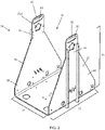
FIG. 2 is an upper perspective view of a chassis according to the first implementation of the present invention. -
FIG. 3 is a view showing several components of the first implementation of a vehicle. -
FIG. 4 is an upper perspective view of the first implementation of a vehicle, with several components isolated from the vehicle. -
FIG. 5 is a view of a section of the first implementation of a vehicle, specifically showing aspects of a tensioning system. -
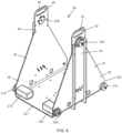
FIG. 6 is an upper perspective view of a chassis used in the first implementation of a vehicle. -
FIG. 7 is an upper perspective view of a stabilization system according to the first implementation of a vehicle. -
FIG. 8 is an upper perspective view of a second implementation of a vehicle. -
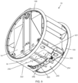
FIG. 9 is a lower perspective view of the second implementation of a vehicle. -
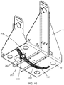
FIG. 10 is a lower perspective view of a chassis and elements of a stabilization system, as used in the second implementation of a vehicle. -
FIG. 11 is a lower perspective view of elements of a stabilization system, as used in the second implementation of a vehicle. -
FIG. 12 is an upper perspective view of a third implementation of a vehicle. -
FIG. 13 is an upper perspective view of the third implementation of a vehicle, with certain elements removed for clarity. -
FIG. 14 is an upper perspective view of a cargo container as used with the third implementation of a vehicle. -
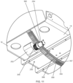
FIG. 15 is an upper perspective view of a cargo container as used with the third implementation of a vehicle, further showing elements of a stabilization system. - Disclosed herein are various implementations of a vehicle. In certain aspects, as shown in
FIGS. 1-4 , the present invention provides avehicle 10. Thevehicle 10 includes achassis 14. Thechassis 14 defines aheight 15, alength 16 and awidth 17 of thevehicle 10. In certain implementations, thechassis 14 includes afloor 18 and afirst sidewall 22. Thefloor 18 and thefirst sidewall 22 are joined at a substantially right angle, although other arrangements are within the scope of this disclosure. Thefirst sidewall 22 includes a first sidewallupper portion 24, a first sidewalllower portion 28 and afirst sidewall aperture 30. Thefirst sidewall aperture 30 is disposed at the first sidewallupper portion 24 and forms afirst handle 32. - The
chassis 14 also includes asecond sidewall 34. Thefloor 18 and thesecond sidewall 34 are joined at a substantially right angle, although other arrangements are within the scope of this disclosure. Thesecond sidewall 34 includes a second sidewallupper portion 36, a second sidewalllower portion 38 andsecond sidewall aperture 40. Thesecond sidewall aperture 40 is disposed at the second sidewallupper portion 36 and forms asecond handle 42. - In certain implementations, the
chassis 14 includes acargo cavity 50, as best shown inFIGS. 2 and4 . Thecargo cavity 50 is configured to support, or facilitate the support of, acargo volume 54, in which various cargos can be stored. In some implementations, a cargo insert 58 is removably disposed within thecargo volume 54. Thecargo insert 58 is designed to support and/or secure various cargos. Thecargo insert 58 includes alip 62 that facilitates the removal of thecargo insert 58 from thecargo volume 54, and also facilitates a secure engagement between thecargo insert 58 and thecargo volume 54 when thecargo insert 58 is removably disposed within thecargo volume 54 by interfacing with anupper edge 66 of thecargo volume 54. Thecargo cavity 50 also includes asensor shelf 70 for mounting various sensors and electronic components, which will be described below. Abattery channel 72 may be disposed in one or more of thecargo cavity 50,cargo volume 54 and the cargo insert 58. In some implementations, the total weight of thevehicle 10 is between 9,07 and 27,22 kilogram (20 and 60 pounds). Additionally, various fairings (not shown) can be added to the vehicle to provide additional user interface features and performance characteristics. - In certain aspects, the present disclosure provides for a
wheel 100 as best shown inFIG. 4 . Thewheel 100 is rotatably attached to thechassis 14. In some implementations, thewheel 100 may be rotatably attached to another part of thevehicle 10. Thewheel 100 includes aperimeter 101, ageometric center 102 and adiameter 103. In some implementations, thediameter 103 is between 0,30 and 0,71 metre (12 and 28 inches), inclusive. In certain implementations, the diameter of thewheel 100 is at least 75% of theheight 15,length 16 and/orwidth 17 of thechassis 14 and/orvehicle 10. Thewheel 100 also includes arim 104 substantially defining anouter surface 110 of thewheel 100. Atire 108 is disposed around therim 104 and may be removably mounted to therim 104, such that thetire 108 rotates along with therim 104. Thetire 108 is made from a rubber, polymer or any other suitable material. Thetire 108 serves to protect thewheel 100 andvehicle 10, and further provides a frictional contact between thewheel 100 and a ground surface to enhance the performance of thevehicle 10. - The
wheel 100 also includes aninner surface 112 and theinner surface 112 is disposed on an opposite side of thewheel 100 from theouter surface 110. Theinner surface 112 includes a plurality ofteeth 116. The plurality ofteeth 116 are connected to therim 104 such that a rotation of the plurality ofteeth 116 corresponds to a rotation of therim 104. In some implementations, the plurality ofteeth 116 are integrally formed with theinner surface 112. In some implementations, the plurality ofteeth 116 are, permanently or removably, attached to theinner surface 112. In these implementations, theinner surface 112 and the plurality ofteeth 116 effectively form aring gear 120 on theinner surface 112 of thewheel 100. The plurality ofteeth 116 and theinner surface 112 are formed from a metal, metal alloy, ceramic, polymer, composite material or any other suitable material. - In some implementations, the plurality of
teeth 116 are disposed on atoothed belt 124, as best shown inFIG, 4 . Thetoothed belt 124 is attached, permanently or removably, to theinner surface 112 of thewheel 100. The plurality ofteeth 116 on thetoothed belt 124 are connected to therim 104 such that a rotation of the plurality ofteeth 116 results in a rotation of therim 104. Thetoothed belt 124 is formed of a metal, metal alloy, ceramic, polymer, composite material or any other suitable material. - The
vehicle 10 includes asecond wheel 126 having asecond perimeter 130, a secondgeometric center 134 and asecond diameter 138, asecond rim 142, asecond tire 146, a secondouter surface 150, a secondinner surface 154, a second plurality ofteeth 158, asecond ring gear 162 and a secondtoothed belt 166, as best shown inFIGS. 1 and4 . In some implementations, thesecond diameter 138 is between 0,30 and 0,71 metre (12 and 28 inches), inclusive. Each of these 'second' elements connects, and operatively associates, with one another in the same manner as their above-described corresponding elements. For example, thesecond tire 146 and thesecond rim 142 connect, and operatively associate, with each other in the same manner as thetire 108 and therim 104. Awheel axis 169 passes through thegeometric center 102 of thefirst wheel 100 and thegeometric center 134 of the second wheel. - Aspects of the present invention additionally include a
drive system 190 as best shown inFIGS. 4 and6 . Thedrive system 190 is configured to generate a drive force and/or transmit the drive force to thewheel 100. Thedrive system 190 includes amotor 194, which is an electric motor. In some implementations, an internal combustion engine is also possible. Themotor 194 receives electrical energy from abattery 202 or fuel cell, or fuel from a fuel source or fuel tank (not shown). Themotor 194 rotates adrive gear 204 via anaxle 208 disposed between themotor 194 and thedrive gear 204. Thedrive gear 204, in certain implementations, includes teeth formed in non-linear, or angled, shapes, and the plurality ofteeth 116 include mechanically engaging, or the same, shapes. Thedrive gear 204, in certain implementations, includes teeth formed in chevron shapes, and the plurality ofteeth 116 include mechanically engaging, or the same, shapes. Additional elements, such as a transmission or gear box (not shown), may be disposed between themotor 194 and thedrive gear 204 and/or may convey a drive force from themotor 194 to thedrive gear 204. Thedrive gear 204 includes a plurality ofdrive gear teeth 210 that rotate along with, and are rigidly attached to, thedrive gear 204. - The plurality of
drive gear teeth 210 engage with, and drive, the plurality ofteeth 116 of thewheel 100. In operation, themotor 194 rotates theaxle 208 and thedrive gear 204, which rotates thewheel 100 through the engagement of the plurality ofteeth 116 and the plurality ofdrive gear teeth 210. Anidler gear 212 also engages with thewheel 100 via the plurality ofteeth 116, and is rotatably attached to thechassis 14. Asecond motor 213 provides a drive force to thesecond wheel 126 via a second axle 214 and asecond drive gear 215, in a similar manner as themotor 194 and thewheel 100. - Additionally, in certain implementations the
vehicle 10 includes atensioning system 216 as best shown inFIGS. 5 and6 . Thetensioning system 216 includes atensioner gear 220 and various means for tensioning thewheel 100 relative to thechassis 14, or to thedrive gear 204, via thetensioner gear 220. In some implementations, thetensioning system 216 includes atensioner gear aperture 224 located within thechassis 14. In an implementation, thetensioner gear aperture 224 is disposed within the first orsecond sidewall tensioner gear insert 228 is rotatably disposed in thetensioner gear aperture 224 and includes atensioner gear mount 232. Thetensioner gear 220 rotatably attaches, directly or indirectly, to thetensioner gear mount 232. Thetensioner gear mount 232 is located at a location on thetensioner gear insert 228 discrete from ageometric center 236 of thetensioner gear insert 228. - When the
tensioner gear insert 228 is rotated in thetensioner gear aperture 224, which may be performed manually, the location of thetensioner gear mount 232 is changed relative to the locations of theidler gear 212 and thedrive gear 204. As thetensioner gear 220 is rotatably attached to thetensioner gear mount 232 away from the geometric center of thetension gear insert 228, the location of thetensioner gear 220 relative to theidler gear 212 and thedrive gear 204 is changed as thetensioner gear mount 232 is rotated within thetensioner gear aperture 224. In this manner, as thewheel 100 is substantially inflexible and the locations of theidler gear 212 and thedrive gear 204 are substantially fixed relative to thechassis 14, the tension of thewheel 100 when mounted to the combination of theidler gear 212,drive gear 204 andtensioner gear 220 can be adjusted by rotating thetensioner gear mount 232 within thetensioner gear aperture 224. Additionally, in an implementation, theidler gear 212,drive gear 204 andtensioner gear mount 232 generally form vertices of a substantially equilateral triangle when mounted on thechassis 14. - In some implementations, the
vehicle 10 includes astabilization system 250, as illustrated inFIG. 7 . Among other features, thestabilization system 250 is configured to move, rotate and/or translate acounterweight 252. The motion of thecounterweight 252 affects the center of mass of thechassis 14 and/or thevehicle 10, and therefore affects a pitch of thechassis 14 and/or thevehicle 10. Astabilization motor 254, which is an electric motor (although other motor types are within the scope of this disclosure), provides a drive force for moving thecounterweight 252 via astabilization drive 258. Thestabilization drive 258 may include various elements including gears, belts, chains, pulleys, translators and/or transmissions, among other features, and will be described below in further detail. - According to the present invention, the
vehicle 10 includes one ormore sensors 276, as best shown inFIG. 4 . The one ormore sensors 276 include apitch sensor 280 for sensing a pitch of thevehicle 10 and/orchassis 14. The one ormore sensors 276 may also include anacceleration sensor 284 for sensing an acceleration of thevehicle 10 and/orchassis 14. The one ormore sensors 276 may also include aspeed sensor 288 for sensing a speed of thevehicle 10 and/orchassis 14. One or more of thesensors sensor shelf 70. Thevehicle 10 further includes aprocessor 292 and amemory 294 in electronic communication with thesensor 276. - The one or
more sensors 276 determine and output a measurement of a state of thevehicle 10 and/orchassis 14. The determination is sent to thememory 294 andprocessor 292, which orders an operation of thestabilization motor 254. For example, thepitch sensor 280 determines a pitch of thevehicle 10 and/orchassis 14 and outputs the measured pitch to thememory 294 andprocessor 292, which command an operation of the stabilization motor. In this manner thevehicle 10 can determine, by aprocessor 292 and based onsensor 276 data, an orientation, acceleration or speed of thevehicle 10 and/orchassis 14. In some implementations, thesensor 276 can make multiple determinations at different times or continuously to determine a change in orientation, acceleration or speed of thevehicle 10 and/orchassis 14, or rate of change in orientation, acceleration or speed of thevehicle 10. - In some implementations, once the above determination of an orientation, acceleration or speed, or of a change (or rate of change) in the orientation, acceleration or speed, of the
vehicle 10 and/orchassis 14 is made, theprocessor 292 and/ormemory 294 control thestabilization motor 254 to move thecounterweight 252 in response to the measured determination. In one aspect, theprocessor 292 and/ormemory 294 control thestabilization motor 254 to move thecounterweight 252 to maintain a substantiallyconstant vehicle 10 and/orchassis 14 orientation about an axis 300 passing through thegeometric centers second wheels counterweight 252 is coupled to thechassis 14 such that thecounterweight 252 can adjust an orientation of thevehicle 10 and/orchassis 14 in response to a change in pitch of thevehicle 10 and/orchassis 14 about an axis 300 passing through thegeometric centers second wheels - In some implementations of the present invention, once the above determination of an orientation, acceleration or speed, or of a change in the orientation, acceleration or speed, of the
vehicle 10 and/orchassis 14 is made, theprocessor 292 and/ormemory 294 control themotor 194 to move thewheel 100 in response to the measured determination. In some implementations, once the above determination of an orientation, acceleration or speed, or of a change in the orientation, acceleration or speed, of thevehicle 10 and/orchassis 14 is made, theprocessor 292 and/ormemory 294 control thestabilization motor 254 to move thecounterweight 252 in response to the measured determination and further control themotor 194 to move thewheel 100 in response to the measured determination. - In some implementations, a motion of the
counterweight 252 can be determined using various algorithms. In one example, acceleration of thevehicle 10 can be characterized by solving a torque balance equation. The resultant equation of motion is represented byEquation 1, shown below, in some implementations:
- In
Equation 1, R =Rotational acceleration of chassis and payload, I_robot=Rotational moment of inertia of chassis and payload, τ_motor=Torque of the motor, m_chassis=Mass of the chassis, L_chassis=Distance from origin to center of chassis (positive down), m_payload=Mass of the payload (cargo), L_payload=Vertical distance from origin to center of payload(positive down), x=Horizontal distance from origin to center of payload (positive forward), and C_damping=Damping coefficient, proportional to angular velocity. - From the calculation of
Equation 1, "R", or the rotational acceleration of the chassis and payload, can be used to determine a movement of thecounterweight 252. A proportional-integral-derivative (PID) controller can be used with a simple formulation, represented byEquation 2, illustrated below:
Equation 2, P=Proportional gain, I=Integral gain, dt=time increment, D=Derivative gain, H=movement of thecounterweight 252. - In some implementations, the
counterweight 252 is moved along atrack 310 by thestabilization motor 254. Thetrack 310 may be disposed on thechassis 14 or on another part of thevehicle 10. - In one aspect of the present invention, the
vehicle 10 includes alinear track 320 as best shown inFIGS. 1-7 . Thelinear track 320 is disposed longitudinally on thechassis 14 and extends toward a front of thechassis 321 and toward a rear of thechassis 322. Thelinear track 320 is disposed between thechassis 14 and thecargo volume 54, and is also attached to thechassis floor 18. Aworm gear 324 is disposed within thelinear track 320. In some implementations, thestabilization motor 254 rotates theworm gear 324 via a belt (not shown). Atranslator 328 is rotatably connected with theworm gear 324 and is translated along theworm gear 324 as theworm gear 324 rotates. Aslider 332 is attached, directly or indirectly, to thetranslator 328 such that theslider 332 moves with thetranslator 328 as thetranslator 328 is translated along theworm gear 324 upon a rotation thereof. Further, amount 336 is attached to theslider 332 and moves along with theslider 332. Themount 336 also attaches to thecargo volume 54, which moves along with themount 336. Thecargo volume 54, any contents therein and/or the translating elements (328, 332, 336) thus comprise thecounterweight 252. In other embodiment, a rack-and-pinion arrangement could be used to move thecounterweight 252. - In this arrangement, the
stabilization motor 254 moves thetranslator 328, and thus thecounterweight 252, towards the front and rear of thechassis stabilization motor 254 moves thetranslator 328, and thus thecounterweight 252, towards the front and rear of thechassis vehicle 10 and/orchassis 14 made by thesensor 276, and to a corresponding command from theprocessor 292 and/ormemory 294. In some implementations, thebattery 202 is thecounterweight 252, and is thus moved towards the front and rear of thechassis stabilization motor 254. In some implementations, thebattery 202 is moved towards the front and rear of thechassis battery channel 72 by thestabilization motor 254. Further, in some implementations, thebattery 202 is disposed below thechassis 14. - In some implementations of the present invention, the
vehicle 10 includes anarcuate track 350 as best shown inFIGS. 8-11 . Thearcuate track 350 is disposed substantially longitudinally on thechassis 14 and extends toward the front of thechassis 321 and toward the rear of thechassis 322. Thearcuate track 350 is disposed below thechassis floor 18 and is further attached to thechassis floor 18. However, thearcuate track 350 may also be disposed at other locations on thevehicle 10 orchassis 14. Thecounterweight 252 is attached to thestabilization motor 254, and the attachedcounterweight 252 andstabilization motor 254 travel along an arcuate path, and/or along thearcuate track 350, through a drive force generated by thestabilization motor 254. In particular, thestabilization motor 254 rotates a travellinggear 355 rotatably connected with thestabilization motor 254. The travellinggear 355 engages with a plurality ofarcuate teeth 356 disposed along a side of thearcuate track 350. Acurved member 357 is disposed proximate to a side of thearcuate track 350 and is spaced a distance from thearcuate track 350, thus forming anarcuate slot 358 between thearcuate track 350 and thecurved member 357. A retainingmember 362 connected to thecounterweight 252 and/or thestabilization motor 254 is disposed within thearcuate slot 358 and, by various means including an interlocking fit with thearcuate track 350 and/orarcuate slot 350 or a mechanically biased or interfering relationship with thearcuate track 350 and/or thecurved member 357, retains the retainingmember 362,counterweight 252 andstabilization motor 254 to thearcuate track 350 as the retainingmember 362,counterweight 252 andstabilization motor 254 travel along an arcuate path along thearcuate track 350. - In some implementations, the
stabilization motor 254 moves thecounterweight 252 along an arcuate path. Further, in some implementation, thestabilization motor 254 moves thecounterweight 252 along thearcuate track 350 and towards the front and rear of thechassis stabilization motor 254 moves thecounterweight 252 towards the front and rear of thechassis vehicle 10 and/orchassis 14 made by thesensor 276, and to a corresponding command from theprocessor 292 and/ormemory 294. In some implementations, thebattery 202 is disposed below thechassis 14. In some implementations, a motion of thecounterweight 252 can be determined using various algorithms. In some implementations, a motion of thecounterweight 252 can be determined using a proportional-integral-derivative (PID) controller algorithm. - In some implementations of the present invention, the
vehicle 10 includes aharness 370 as best shown inFIGS. 12-15 . Theharness 370 includes a plurality ofcross members 374. Ayoke 378 is rigidly attached to theharness 370 such that theyoke 378 and harness 370 rotate and move together. As shown inFIGS. 12 ,14 and15 , acargo container 382 is provided, and is rotatably disposed within theharness 370 and below theyoke 378. In some implementations, a plurality ofrollers 390 rotatably suspends and supports thecargo container 382 within theharness 370. Eachroller 390 includes arotational end 394 and anopposite end 398. Eachopposite end 398 is attached to theharness 370 and eachrotational end 394 projects inward from theharness 370, as best shown inFIGS. 13-15 . Eachrotational end 394 rotates relative to each respectiveopposite end 398. Eachrotational end 394 rotatably suspends and supports thecargo container 382, and rotatably interacts with aroller track 402 disposed on thecargo container 382, as best shown inFIGS. 14 and15 . When suspended and supported by therollers 390, thecargo container 382 rotates about acargo container axis 406. The cargo container further includes agroove 410 including a plurality ofgroove teeth 414. Thegroove teeth 414 mechanically engage with astabilization drive gear 418, which is rotated by acargo container motor 419. Thecargo container motor 419, a harness motor (not shown) and asecond harness motor 440 are attached to the harness 270 and/or theyoke 378. The harness motor (not shown) and thesecond harness motor 440 are attached to the harness 270 on an exterior side of the harness 270, and are positioned relative to the harness as best shown inFIG. 12 . Thesecond harness motor 440 is attached to the harness 270 via a secondharness motor mount 460. One or more idler gears 212 are also rotatably attached to the harness 270. In this arrangement, thecargo container 382 and any contents therein, functions as thecounterweight 252. Further, thecargo container motor 419 is attached to a portion of theharness 370 and/oryoke 378. Additionally, thecargo container motor 419 may attach to theharness 370 via aharness attachment mount 450, as best shown inFIG. 13 . - In this arrangement, the
cargo container motor 419 rotates thecargo container 382, orcounterweight 252, about thecargo container axis 406 according to a drive force provided by thecargo container motor 419. In some implementations, thecargo container motor 419 moves thecargo container 382, orcounterweight 252, about thecargo container axis 406 in response to a determination of an orientation, acceleration or speed, or of a change in the orientation, acceleration or speed, of thevehicle 10 and/orchassis 14 made by thesensor 276, and to a corresponding command from theprocessor 292 and/ormemory 294. In some implementations, thebattery 202 is disposed within thecargo container 382. Further, in some implementations, thebattery 202 is disposed below thecargo container 382. In some implementations, a motion of thecounterweight 252 can be determined using various algorithms. In some implementations, a motion of thecounterweight 252 can be determined using a proportional-integral-derivative (PID) controller algorithm. - The disclosed systems and methods are well adapted to attain the ends and advantages mentioned as well as those that are inherent therein. Furthermore, no limitations are intended to the details of construction or design herein shown, other than as described in the claims below. While compositions and methods are described in terms of "comprising," "containing," or "including" various components or steps, the compositions and methods can also "consist essentially of" or "consist of" the various components and steps. All numbers and ranges disclosed above may vary by some amount. Whenever a numerical range with a lower limit and an upper limit is disclosed, any number and any included range falling within the range is specifically disclosed. In particular, every range of values (of the form, "from about a to about b," or, equivalently, "from approximately a to b," or, equivalently, "from approximately a-b") disclosed herein is to be understood to set forth every number and range encompassed within the broader range of values. Also, the terms in the claims have their plain, ordinary meaning unless otherwise explicitly and clearly defined by the patentee. Moreover, the indefinite articles "a" or "an," as used in the claims, are defined herein to mean one or more than one of the element that it introduces.
- As used herein, the phrase "at least one of" preceding a series of items, with the terms "and" or "or" to separate any of the items, modifies the list as a whole, rather than each member of the list (i.e., each item). The phrase "at least one of" allows a meaning that includes at least one of any one of the items, and/or at least one of any combination of the items, and/or at least one of each of the items. By way of example, the phrases "at least one of A, B, and C" or "at least one of A, B, or C" each refer to only A, only B, or only C; any combination of A, B, and C; and/or at least one of each of A, B, and C.
Claims (14)
- A two-wheeled vehicle (10), comprising:a chassis (14) having a height (15), a length (16) and a width (17);a first wheel (100) rotatably connected to the chassis (14), the first wheel (100) having a perimeter (101), a diameter (103) and a geometric center (102), and the diameter (103) of the first wheel (100) being at least 75% of the height (15) of the chassis (14);a motor (194) for providing a drive energy to the first wheel (100);an axle (208) rotated by the motor (194);a drive gear (204) connected with the axle (208) such that the drive gear (204) rotates with a rotation of the axle (208);a plurality of teeth (116) disposed about the first wheel (100) and mechanically engaged with the drive gear (204) at a location closer to the perimeter (101) of the first wheel (100) than to the geometric center (102) of the first wheel (100), characterized bya pitch sensor (280) for sensing a pitch of the chassis (14); anda stabilization system (250) configured to rotate a cargo container (382) about a cargo container axis (406) responsive to an output of the pitch sensor (280) for adjusting an orientation of the chassis (14).
- The two-wheeled vehicle (10) of claim 1, wherein the plurality of teeth (116) mechanically engage with the drive gear (204) at about the perimeter (101) of the first wheel (100), and, optionally,
comprising a ring gear (120) including the plurality of teeth (116) coupled to an inner surface (112) of the first wheel (100). - The two-wheeled vehicle (10) of claim 1, including a tensioner gear (220) and an idler gear (212) coupled to the chassis (14), wherein the tensioner gear (220) and idler gear (212) are mechanically engaged with the plurality of teeth (116) disposed about the first wheel (100), and optionally
wherein the tensioner gear (220), idler gear (212) and drive gear (204) couple to the chassis (14) at positions that correspond to vertices of a substantially equilateral triangle. - The two-wheeled vehicle of claim 1, comprising a cargo volume (54) supported by the chassis (14).
- The two-wheeled vehicle (10) of claim 4, comprising a cargo (58) insert removably disposed within the cargo volume (54).
- The two-wheeled vehicle (10) of claim 1, wherein the two-wheeled vehicle (10) includes a stabilization system (250) configured to move a counterweight (252) along a linear track (320) responsive to an output of the pitch sensor (280) for adjusting an orientation of the chassis (14), or, optionally,
wherein the two-wheeled vehicle (10) includes a stabilization system (250) configured to move the counterweight (252) along an arcuate track (350) responsive to an output of the pitch sensor (280) for adjusting an orientation of the chassis (14). - The two-wheeled vehicle (10) of claim 1, wherein the diameter (103) of the first wheel (100) is at least 75% of the length (16) of the chassis (14).
- The two-wheeled vehicle (10) of claim 1, further comprising:a second wheel (126) rotatably connected to the chassis (14) on an opposite side of the chassis (14) from the side of the chassis (14) rotatably connected to the first wheel (100), the second wheel (126) having a perimeter (130), a diameter (138), and a geometric center (134); anda second motor (213) for providing a drive energy to the second wheel (126), independent of the motor (194) providing the drive energy to the first wheel (100), via a second drive gear (215), wherein the second drive gear (215) is mechanically engaged with the second wheel (126) at a location closer to the perimeter (130) of the second wheel (126) than to the geometric center (134) of the second wheel (126).
- The two-wheeled vehicle (10) of claim 1, further comprising:a sensor (276);a counterweight adjustment drive configured to move a counterweight (252) towards the front (321) or towards the rear (322) of the chassis in response to a change in pitch of the chassis (14); anda processor (292) in communication with the sensor (276) and the counterweight adjustment drive, the processor (292) configured to control the counterweight adjustment drive in response to a measurement output by the sensor (276).
- The two-wheeled vehicle (10) of claim 9, wherein the processor (292) controls the counterweight adjustment drive to move the counterweight (252) to maintain a substantially constant chassis orientation.
- The two-wheeled vehicle (10) of claim 9, wherein the counterweight (252) comprises a cargo volume (54) or an electric battery (202).
- The two-wheeled vehicle (10) of claim 9, wherein the sensor (276) comprises an accelerometer configured to measure an acceleration of the two-wheeled vehicle (10).
- The two-wheeled vehicle (10) of claim 9, wherein the counterweight adjustment drive moves the counterweight (252) along a track (310) and wherein the track (310) is disposed between the chassis (14) and a cargo volume (54).
- The two-wheeled vehicle (10) of claim 13, wherein the counterweight adjustment drive is configured to move the counterweight (252) towards the front (321) or towards the rear (322) of the chassis (14) along an arcuate path.
Applications Claiming Priority (1)
| Application Number | Priority Date | Filing Date | Title |
|---|---|---|---|
| PCT/US2016/057529 WO2018075013A1 (en) | 2016-10-18 | 2016-10-18 | Vehicle having non-axial drive and stabilization system |
Publications (2)
| Publication Number | Publication Date |
|---|---|
| EP3529098A1 EP3529098A1 (en) | 2019-08-28 |
| EP3529098B1 true EP3529098B1 (en) | 2023-02-08 |
Family
ID=57227116
Family Applications (1)
| Application Number | Title | Priority Date | Filing Date |
|---|---|---|---|
| EP16790806.0A Active EP3529098B1 (en) | 2016-10-18 | 2016-10-18 | Vehicle having non-axial drive and stabilization system |
Country Status (5)
| Country | Link |
|---|---|
| US (1) | US11370497B2 (en) |
| EP (1) | EP3529098B1 (en) |
| JP (1) | JP2020503204A (en) |
| CA (1) | CA3040928A1 (en) |
| WO (1) | WO2018075013A1 (en) |
Families Citing this family (10)
| Publication number | Priority date | Publication date | Assignee | Title |
|---|---|---|---|---|
| EP3269680B1 (en) | 2016-07-14 | 2020-09-30 | Toyota Material Handling Manufacturing Sweden AB | Floor conveyor |
| EP3269678B1 (en) | 2016-07-14 | 2019-03-06 | Toyota Material Handling Manufacturing Sweden AB | Floor conveyor |
| EP3269679B2 (en) | 2016-07-14 | 2024-12-04 | Toyota Material Handling Manufacturing Sweden AB | Floor conveyor |
| EP3529098B1 (en) | 2016-10-18 | 2023-02-08 | Piaggio Fast Forward, Inc. | Vehicle having non-axial drive and stabilization system |
| IT201700114497A1 (en) | 2017-10-11 | 2019-04-11 | Piaggio Fast Forward Inc | TWO-WHEEL VEHICLE WITH LINEAR STABILIZATION SYSTEM |
| CN113892068A (en) | 2018-05-01 | 2022-01-04 | 皮亚吉奥科技有限公司 | Method for determining a behaviour model of an autonomous vehicle, autonomous vehicle and method for navigating an autonomous vehicle |
| WO2020086606A2 (en) | 2018-10-22 | 2020-04-30 | Piaggio Fast Forward, Inc. | Shifting assembly and mobile carrier comprising same |
| US11716522B2 (en) | 2020-08-06 | 2023-08-01 | Piaggio Fast Forward Inc. | Follower vehicle sensor system |
| USD1010699S1 (en) | 2021-09-21 | 2024-01-09 | Piaggio Fast Forward Inc. | Sensor pack |
| USD1034305S1 (en) | 2021-09-21 | 2024-07-09 | Piaggio Fast Forward Inc. | Mobile carrier |
Citations (2)
| Publication number | Priority date | Publication date | Assignee | Title |
|---|---|---|---|---|
| US20020149172A1 (en) * | 2000-03-01 | 2002-10-17 | Field J. Douglas | Trailer for balancing vehicle |
| DE202007011698U1 (en) * | 2007-08-21 | 2009-01-02 | Wittenbauer, Rudolf, Dipl.-Ing. | two-wheeled vehicle |
Family Cites Families (122)
| Publication number | Priority date | Publication date | Assignee | Title |
|---|---|---|---|---|
| US3123173A (en) | 1964-03-03 | Variable speed drive mechanism | ||
| US282299A (en) * | 1883-07-31 | Traction-engine | ||
| US1819924A (en) | 1929-06-18 | 1931-08-18 | Seppola Asle | Traction device for vehicles |
| US3418005A (en) | 1967-08-28 | 1968-12-24 | Perfection Mfg Company | Garden cart and liner bag assembly |
| US3776353A (en) | 1971-04-12 | 1973-12-04 | E Roth | Three wheeled motor vehicle |
| US3858673A (en) | 1973-10-01 | 1975-01-07 | Albert E Browning | Vehicle having spherical supports |
| US3921740A (en) | 1974-06-12 | 1975-11-25 | Chair E Yacht Inc | Self-propelled vehicle |
| JPS5323019A (en) | 1976-08-16 | 1978-03-03 | Hitachi Ltd | Motor control circuit |
| US4179006A (en) | 1978-02-27 | 1979-12-18 | Lenack Isidore J | Torsionally resilient coupling for transmitting rotary motion |
| US4222452A (en) | 1979-04-04 | 1980-09-16 | International Harvester Company | Power steering mechanism for cotton pickers |
| JPS59195965A (en) | 1983-04-19 | 1984-11-07 | 京浜工業株式会社 | Replacement of bottom plate of tank |
| GB8515992D0 (en) | 1985-06-25 | 1985-07-31 | Hester R | Wheelchair |
| US4714140A (en) | 1986-03-17 | 1987-12-22 | Hatton John H | Multi-axis articulated all terrain vehicle |
| US4986387A (en) | 1989-08-07 | 1991-01-22 | Teledyne Princeton, Inc. | Fork-lift truck having three drive wheels with third wheel steerable |
| FR2654927B1 (en) | 1989-11-28 | 1994-02-11 | Pierre Jose Soto | REMOVABLE WHEELCHAIR. |
| US5094375A (en) * | 1990-04-23 | 1992-03-10 | Durakon Industries, Inc. | Tray combinations |
| JPH0524572A (en) * | 1991-07-23 | 1993-02-02 | Toyota Autom Loom Works Ltd | Bicycle |
| US5439240A (en) | 1991-10-21 | 1995-08-08 | Tichenor; Clyde L. | Balance shifted personal carriage |
| US5248011A (en) | 1992-01-23 | 1993-09-28 | Richards Donald C | Three wheeled vehicle having driven front wheels and steerable rear wheel |
| US5322140A (en) | 1992-02-03 | 1994-06-21 | Amigo Mobility International, Inc. | Steering systems for four-wheeled carts |
| JPH0620176U (en) | 1992-05-23 | 1994-03-15 | 久 尾上 | Special car |
| US5343974A (en) | 1992-07-10 | 1994-09-06 | Rabek Jan W | An electrically powered motor vehicle |
| JP3448817B2 (en) | 1992-07-25 | 2003-09-22 | 孝寛 星野 | Independent motorcycle |
| JPH0661680A (en) | 1992-08-05 | 1994-03-04 | Ten Kk | Working method of radio wave anechoic enclosure and shield room, and radio wave absorbent unit |
| JPH06134049A (en) | 1992-10-22 | 1994-05-17 | Suzuki Motor Corp | Golf cart |
| US5366036A (en) | 1993-01-21 | 1994-11-22 | Perry Dale E | Power stand-up and reclining wheelchair |
| US5558174A (en) | 1994-01-26 | 1996-09-24 | Schaeff, Incorporated | Drive train assembly |
| US6311794B1 (en) | 1994-05-27 | 2001-11-06 | Deka Products Limited Partneship | System and method for stair climbing in a cluster-wheel vehicle |
| EP0705724A3 (en) | 1994-10-07 | 1998-06-10 | Z.E.V. S.R.L. | Motor vehicle with balanced suspensions and increased stability |
| US6561294B1 (en) | 1995-02-03 | 2003-05-13 | Deka Products Limited Partnership | Balancing vehicle with passive pivotable support |
| JPH0920250A (en) | 1995-07-07 | 1997-01-21 | Nikon Corp | Moving equipment |
| US5669619A (en) | 1995-08-22 | 1997-09-23 | Kim; Il Yoo | Portable wheelchair |
| JP3703554B2 (en) | 1996-02-14 | 2005-10-05 | ヤマハ発動機株式会社 | Wheelchair with auxiliary power |
| US5722501A (en) | 1996-05-24 | 1998-03-03 | Teftec Corporation | Bevel steering gear integrated drive transmission |
| NL1007045C2 (en) | 1997-09-16 | 1999-03-25 | Brinks Westmaas Bv | Tilting vehicle. |
| ATE300932T1 (en) | 1999-03-15 | 2005-08-15 | Deka Products Lp | WHEELCHAIR CONTROL SYSTEM AND METHOD |
| US6260645B1 (en) * | 1999-04-22 | 2001-07-17 | Daimlerchrysler Corporation | Electric vehicle with a movable battery tray mounted between frame rails |
| US6553271B1 (en) | 1999-05-28 | 2003-04-22 | Deka Products Limited Partnership | System and method for control scheduling |
| JP2000355293A (en) | 1999-06-15 | 2000-12-26 | National Jitensha Kogyo Kk | Electric nursing bicycle |
| US20010042650A1 (en) | 1999-10-20 | 2001-11-22 | Lely Research Holding A.G., A Swiss Limited Liability Co. | Passenger vehicle |
| NL1013353C2 (en) * | 1999-10-20 | 2001-04-23 | Lely Res Holding | Vehicle. |
| US7017696B2 (en) | 2000-02-14 | 2006-03-28 | Anadish Kumar Pal | Electric motor vehicle with passenger opening through ring motor |
| JP2001339812A (en) | 2000-03-19 | 2001-12-07 | Kazumichi Fujioka | Electric motor car |
| GB0203109D0 (en) | 2002-02-09 | 2002-03-27 | Sunrise Medical Ltd | Propulsion device |
| JP2004129435A (en) * | 2002-10-04 | 2004-04-22 | Sony Corp | Transfer device, control method, and drive mechanism |
| US6880654B2 (en) | 2003-03-28 | 2005-04-19 | Paul J. Plishner | Vehicle with a distributed motor |
| US7185726B2 (en) | 2003-07-21 | 2007-03-06 | Young Grant E | Bicycle with optional power assist |
| US7124854B2 (en) | 2003-09-12 | 2006-10-24 | Jui Tien Huang | Transmission device of vehicle |
| US6974399B2 (en) | 2004-02-11 | 2005-12-13 | Chiu-Hsiang Lo | Hub motor mechanism |
| US7938210B2 (en) | 2004-06-15 | 2011-05-10 | Massachusetts Institute Of Technology | Wheel-embedded suspension |
| JP4408789B2 (en) | 2004-10-25 | 2010-02-03 | 三洋電機株式会社 | Electric vehicle drive device and electric wheelchair provided with the same |
| JP2006123854A (en) * | 2004-11-01 | 2006-05-18 | Matsushita Electric Ind Co Ltd | Luggage transport robot |
| US20060254841A1 (en) | 2005-05-16 | 2006-11-16 | Strong Russell W | Vehicle with adjustable axle system for actively maintaining stability |
| US7581611B1 (en) * | 2005-06-03 | 2009-09-01 | Rehco, Llc | Two-wheel vehicle with a tilt mechanism and stability mechanism |
| US7337862B1 (en) | 2005-06-03 | 2008-03-04 | Rehco, Llc | Mono-wheel vehicle with tilt mechanism |
| CN100557539C (en) | 2005-07-26 | 2009-11-04 | 松下电器产业株式会社 | Inverted two-wheel walking robot and control method thereof |
| US7996109B2 (en) | 2005-10-14 | 2011-08-09 | Aethon, Inc. | Robotic ordering and delivery apparatuses, systems and methods |
| KR200412471Y1 (en) | 2005-12-30 | 2006-03-28 | 장이석 | Electric cart |
| WO2008013568A2 (en) | 2005-12-30 | 2008-01-31 | Irobot Corporation | Autonomous mobile robot |
| US8002060B2 (en) | 2006-02-17 | 2011-08-23 | Honda Motor Co., Ltd. | Vehicle wheel driving apparatus and electric motor |
| JP3960553B1 (en) | 2006-03-31 | 2007-08-15 | 本田技研工業株式会社 | Wheel rotation device for in-wheel motor vehicle |
| WO2007129505A1 (en) | 2006-05-09 | 2007-11-15 | Equos Research Co., Ltd. | Vehicle, characteristic value estimating device, and loaded article determination device |
| JP2007313980A (en) | 2006-05-24 | 2007-12-06 | Masanobu Yatsugi | Wheel unit |
| DE102006038396A1 (en) | 2006-08-15 | 2008-02-21 | Kordel Antriebstechnik Gmbh | Frontachsgetriebe |
| JP4957889B2 (en) | 2006-08-29 | 2012-06-20 | 株式会社エクォス・リサーチ | Traveling vehicle |
| US8083013B2 (en) | 2006-12-06 | 2011-12-27 | The Regents Of The University Of California | Multimodal agile robots |
| WO2008067822A2 (en) | 2006-12-07 | 2008-06-12 | Nordict A/S | A motorised multi-purpose driving wheel |
| US20080245593A1 (en) | 2007-04-03 | 2008-10-09 | Kim Richard J | Hybrid light electric vehicle with all-wheel power train |
| JP4735598B2 (en) | 2007-04-27 | 2011-07-27 | トヨタ自動車株式会社 | Inverted wheel type moving body and control method thereof |
| CN101687528B (en) | 2007-06-29 | 2013-03-06 | 爱考斯研究株式会社 | Vehicle |
| JP5152627B2 (en) * | 2007-08-10 | 2013-02-27 | 株式会社エクォス・リサーチ | vehicle |
| JP4867823B2 (en) | 2007-07-09 | 2012-02-01 | トヨタ自動車株式会社 | Inverted wheel type moving body and control method thereof |
| CN101568465B (en) * | 2007-08-28 | 2011-05-11 | 松下电器产业株式会社 | Inverted two-wheel type carrier, and its control method |
| US7997361B1 (en) | 2007-10-11 | 2011-08-16 | David Anthony Bell | Reverse drive mechanism for wheeled devices |
| JP5150379B2 (en) | 2008-06-18 | 2013-02-20 | 本田技研工業株式会社 | Portable generator |
| KR20080003926U (en) | 2008-07-22 | 2008-09-18 | 박성기 | Wheel without center shaft |
| US20110303035A1 (en) | 2008-07-31 | 2011-12-15 | Niebergall James A | Final drive for a work machine |
| JP5155785B2 (en) | 2008-09-09 | 2013-03-06 | 富士機械製造株式会社 | Operation control method and circuit board working apparatus |
| CN101856554A (en) | 2009-04-07 | 2010-10-13 | 谢春雷 | Golf bag vehicle |
| WO2011106767A2 (en) | 2010-02-26 | 2011-09-01 | Segway Inc. | Apparatus and methods for control of a vehicle |
| FR2957049B1 (en) | 2010-03-02 | 2013-01-04 | Synergethic | NEW ELECTRIC VEHICLE COMPRISING AT LEAST THREE WHEELS |
| US8807250B2 (en) | 2010-03-09 | 2014-08-19 | Shane Chen | Powered single-wheeled self-balancing vehicle for standing user |
| JP5980777B2 (en) | 2010-06-03 | 2016-08-31 | ノルディクト・アクティーゼルスカブNordict A/S | Wheel with electric unit |
| CN102008379B (en) | 2010-10-02 | 2012-11-28 | 胡达广 | Vehicle with entrance at rear |
| JP5624445B2 (en) | 2010-12-08 | 2014-11-12 | Ihi運搬機械株式会社 | Driving method of vehicle moving device |
| GB201104917D0 (en) | 2011-03-24 | 2011-05-04 | Qinetiq Ltd | Gear reduction mechanism |
| NZ592381A (en) | 2011-04-20 | 2013-07-26 | Dynamic Controls | Steering control system for a manual wheelchair for maintaining straight line path of travel |
| FR2976548B1 (en) | 2011-06-17 | 2013-06-07 | Univ Paris Sud 11 | GYROPODE "HUBLESS" OF SIMPLIFIED STRUCTURE |
| US9045190B2 (en) | 2011-08-02 | 2015-06-02 | Shane Chen | Two-wheeled self-balancing motorized personal vehicle with tilting wheels |
| US8684123B2 (en) | 2011-08-02 | 2014-04-01 | Shane Chen | Low-profile two-wheeled self-balancing vehicle with exterior foot platforms |
| KR101272035B1 (en) | 2011-12-07 | 2013-06-10 | 현대자동차주식회사 | Single seat vehicle |
| WO2013176758A1 (en) | 2012-05-22 | 2013-11-28 | Intouch Technologies, Inc. | Clinical workflows utilizing autonomous and semi-autonomous telemedicine devices |
| GB201210010D0 (en) | 2012-06-07 | 2012-07-18 | Mielniczek Witold | PDU propelling driving unit |
| JP5839496B2 (en) | 2012-11-26 | 2016-01-06 | 住友重機械工業株式会社 | Planetary gear set |
| CN205269008U (en) * | 2013-05-06 | 2016-06-01 | 未来动力公司 | Electric vehicles, electric skateboards and self-balancing electric vehicles |
| GB2516619A (en) | 2013-06-17 | 2015-02-04 | Dennis Majoe | Land wheeled drone |
| US9557740B2 (en) | 2013-07-02 | 2017-01-31 | David Crawley | Autonomous mobile platform for service applications |
| GB2506726B (en) | 2013-07-16 | 2014-10-22 | Sergey Nikolaevich Andreev | Two-wheel gyroscope-stabilized vehicle and methods for controlling thereof |
| US20150101876A1 (en) | 2013-10-16 | 2015-04-16 | SXS Gear, LLC | Portal box |
| US20180168896A1 (en) | 2014-03-20 | 2018-06-21 | ResQdevices Pty Ltd. | A transport and components therefor |
| US10076954B2 (en) * | 2014-09-03 | 2018-09-18 | Geo Orbital Inc. | Self-powered planetary orbital wheel assemblies |
| US9701012B1 (en) | 2014-10-30 | 2017-07-11 | Daniel Theobald | Controlled interaction between a mobile robot and another entity |
| CN104590476B (en) * | 2015-02-11 | 2016-03-02 | 鼎力联合(北京)科技有限公司 | The transmission device of driven by power wheel and single-wheel balance truck and two-wheel balance truck |
| JP6424131B2 (en) | 2015-04-16 | 2018-11-14 | 本田技研工業株式会社 | Friction type traveling device |
| KR102002340B1 (en) | 2015-05-04 | 2019-07-22 | 오르비스 휠스, 인코포레이션 | Centerless wheel assembly |
| ES2604311B1 (en) | 2015-08-06 | 2017-12-18 | Universidad De Alicante | PROCEDURE FOR RECOVERY OF INORGANIC FIBERS AT ENVIRONMENTAL TEMPERATURE IN FIBER-RESIN COMPOSITE MATERIALS |
| CN106467111B (en) | 2015-08-20 | 2019-06-07 | 比亚迪股份有限公司 | Vehicle body stable control method, system and automobile |
| KR101598132B1 (en) | 2015-08-24 | 2016-02-26 | 박성기 | Electric wheelchair does not have a central axis |
| CN106627895B (en) | 2016-11-25 | 2020-01-07 | 杭州骑客智能科技有限公司 | A human-machine interactive somatosensory vehicle and its control method and device |
| US10112471B2 (en) * | 2016-05-18 | 2018-10-30 | Sharp Kabushiki Kaisha | Battery-driven traveling device |
| WO2018009587A1 (en) | 2016-07-05 | 2018-01-11 | Orbis Wheels, Inc. | Multi-wheel transmission |
| JP6497369B2 (en) | 2016-09-13 | 2019-04-10 | トヨタ自動車株式会社 | Traveling device |
| US10223848B2 (en) | 2016-09-19 | 2019-03-05 | Intel Corporation | Internet of things smart entry |
| EP3529098B1 (en) | 2016-10-18 | 2023-02-08 | Piaggio Fast Forward, Inc. | Vehicle having non-axial drive and stabilization system |
| US10173738B2 (en) | 2016-10-18 | 2019-01-08 | Piaggio Fast Forward, Inc. | Vehicle having stabilization system |
| US10293676B2 (en) | 2016-10-18 | 2019-05-21 | Piaggio Fast Forward, Inc. | Vehicle having non-axial drive |
| US9764592B1 (en) | 2016-10-27 | 2017-09-19 | Orbis Wheels, Inc. | Ring gear and brake for centerless wheel |
| IT201700007710A1 (en) | 2017-01-25 | 2018-07-25 | Piaggio Fast Forward Inc | Three-Wheeled Vehicle having Non-Axial Drive |
| JP6763318B2 (en) | 2017-02-22 | 2020-09-30 | トヨタ自動車株式会社 | Tilting train |
| JP7083142B2 (en) | 2017-06-19 | 2022-06-10 | 地方独立行政法人東京都立産業技術研究センター | Mobile device, drive control method, and drive control program |
| IT201700114497A1 (en) | 2017-10-11 | 2019-04-11 | Piaggio Fast Forward Inc | TWO-WHEEL VEHICLE WITH LINEAR STABILIZATION SYSTEM |
| CN113892068A (en) | 2018-05-01 | 2022-01-04 | 皮亚吉奥科技有限公司 | Method for determining a behaviour model of an autonomous vehicle, autonomous vehicle and method for navigating an autonomous vehicle |
-
2016
- 2016-10-18 EP EP16790806.0A patent/EP3529098B1/en active Active
- 2016-10-18 JP JP2019521784A patent/JP2020503204A/en active Pending
- 2016-10-18 CA CA3040928A patent/CA3040928A1/en active Pending
- 2016-10-18 WO PCT/US2016/057529 patent/WO2018075013A1/en not_active Ceased
- 2016-10-18 US US16/342,732 patent/US11370497B2/en active Active
Patent Citations (2)
| Publication number | Priority date | Publication date | Assignee | Title |
|---|---|---|---|---|
| US20020149172A1 (en) * | 2000-03-01 | 2002-10-17 | Field J. Douglas | Trailer for balancing vehicle |
| DE202007011698U1 (en) * | 2007-08-21 | 2009-01-02 | Wittenbauer, Rudolf, Dipl.-Ing. | two-wheeled vehicle |
Also Published As
| Publication number | Publication date |
|---|---|
| US20200047826A1 (en) | 2020-02-13 |
| EP3529098A1 (en) | 2019-08-28 |
| US11370497B2 (en) | 2022-06-28 |
| JP2020503204A (en) | 2020-01-30 |
| WO2018075013A1 (en) | 2018-04-26 |
| CA3040928A1 (en) | 2018-04-26 |
Similar Documents
| Publication | Publication Date | Title |
|---|---|---|
| EP3529098B1 (en) | Vehicle having non-axial drive and stabilization system | |
| US10293676B2 (en) | Vehicle having non-axial drive | |
| US10173738B2 (en) | Vehicle having stabilization system | |
| US10351190B2 (en) | Three-wheeled vehicle having non-axial drive | |
| CN111386506B (en) | Two-wheeled vehicle with linear stabilization system | |
| EP2409905B1 (en) | Powered unicycle | |
| CN101568465B (en) | Inverted two-wheel type carrier, and its control method | |
| JP3791663B2 (en) | Omnidirectional moving vehicle and its control method | |
| US8640807B2 (en) | Vehicle | |
| CN112996685B (en) | Shifting assembly and mobile carrier including the same | |
| JP7304553B2 (en) | Traveling mobile body, its control method, and its control program | |
| EP3847087B1 (en) | A monowheel vehicle | |
| EP3844058A1 (en) | Load carrying device for the transport and balancing of loads placed on a two- wheeled vehicle | |
| CN107024938B (en) | Balance system of wheeled robot and control method thereof | |
| KR102295603B1 (en) | The Adjustable Steering wheel rotation texture structure of confined spaces carrying portable small electric car | |
| EP4074586A1 (en) | A utility vehicle | |
| HK40045256A (en) | A monowheel vehicle | |
| HK40045256B (en) | A monowheel vehicle | |
| JP2009149132A (en) | Engine tilting device for single rail conveyor |
Legal Events
| Date | Code | Title | Description |
|---|---|---|---|
| STAA | Information on the status of an ep patent application or granted ep patent |
Free format text: STATUS: UNKNOWN |
|
| STAA | Information on the status of an ep patent application or granted ep patent |
Free format text: STATUS: THE INTERNATIONAL PUBLICATION HAS BEEN MADE |
|
| PUAI | Public reference made under article 153(3) epc to a published international application that has entered the european phase |
Free format text: ORIGINAL CODE: 0009012 |
|
| STAA | Information on the status of an ep patent application or granted ep patent |
Free format text: STATUS: REQUEST FOR EXAMINATION WAS MADE |
|
| 17P | Request for examination filed |
Effective date: 20190509 |
|
| AK | Designated contracting states |
Kind code of ref document: A1 Designated state(s): AL AT BE BG CH CY CZ DE DK EE ES FI FR GB GR HR HU IE IS IT LI LT LU LV MC MK MT NL NO PL PT RO RS SE SI SK SM TR |
|
| AX | Request for extension of the european patent |
Extension state: BA ME |
|
| DAV | Request for validation of the european patent (deleted) | ||
| DAX | Request for extension of the european patent (deleted) | ||
| STAA | Information on the status of an ep patent application or granted ep patent |
Free format text: STATUS: EXAMINATION IS IN PROGRESS |
|
| 17Q | First examination report despatched |
Effective date: 20200716 |
|
| GRAP | Despatch of communication of intention to grant a patent |
Free format text: ORIGINAL CODE: EPIDOSNIGR1 |
|
| STAA | Information on the status of an ep patent application or granted ep patent |
Free format text: STATUS: GRANT OF PATENT IS INTENDED |
|
| INTG | Intention to grant announced |
Effective date: 20220218 |
|
| GRAJ | Information related to disapproval of communication of intention to grant by the applicant or resumption of examination proceedings by the epo deleted |
Free format text: ORIGINAL CODE: EPIDOSDIGR1 |
|
| STAA | Information on the status of an ep patent application or granted ep patent |
Free format text: STATUS: EXAMINATION IS IN PROGRESS |
|
| INTC | Intention to grant announced (deleted) | ||
| GRAP | Despatch of communication of intention to grant a patent |
Free format text: ORIGINAL CODE: EPIDOSNIGR1 |
|
| STAA | Information on the status of an ep patent application or granted ep patent |
Free format text: STATUS: GRANT OF PATENT IS INTENDED |
|
| INTG | Intention to grant announced |
Effective date: 20220831 |
|
| GRAS | Grant fee paid |
Free format text: ORIGINAL CODE: EPIDOSNIGR3 |
|
| GRAA | (expected) grant |
Free format text: ORIGINAL CODE: 0009210 |
|
| STAA | Information on the status of an ep patent application or granted ep patent |
Free format text: STATUS: THE PATENT HAS BEEN GRANTED |
|
| AK | Designated contracting states |
Kind code of ref document: B1 Designated state(s): AL AT BE BG CH CY CZ DE DK EE ES FI FR GB GR HR HU IE IS IT LI LT LU LV MC MK MT NL NO PL PT RO RS SE SI SK SM TR |
|
| REG | Reference to a national code |
Ref country code: GB Ref legal event code: FG4D |
|
| REG | Reference to a national code |
Ref country code: CH Ref legal event code: EP Ref country code: AT Ref legal event code: REF Ref document number: 1547384 Country of ref document: AT Kind code of ref document: T Effective date: 20230215 |
|
| REG | Reference to a national code |
Ref country code: IE Ref legal event code: FG4D |
|
| REG | Reference to a national code |
Ref country code: DE Ref legal event code: R096 Ref document number: 602016077776 Country of ref document: DE |
|
| REG | Reference to a national code |
Ref country code: LT Ref legal event code: MG9D |
|
| P01 | Opt-out of the competence of the unified patent court (upc) registered |
Effective date: 20230425 |
|
| REG | Reference to a national code |
Ref country code: NL Ref legal event code: MP Effective date: 20230208 |
|
| REG | Reference to a national code |
Ref country code: AT Ref legal event code: MK05 Ref document number: 1547384 Country of ref document: AT Kind code of ref document: T Effective date: 20230208 |
|
| PG25 | Lapsed in a contracting state [announced via postgrant information from national office to epo] |
Ref country code: RS Free format text: LAPSE BECAUSE OF FAILURE TO SUBMIT A TRANSLATION OF THE DESCRIPTION OR TO PAY THE FEE WITHIN THE PRESCRIBED TIME-LIMIT Effective date: 20230208 Ref country code: PT Free format text: LAPSE BECAUSE OF FAILURE TO SUBMIT A TRANSLATION OF THE DESCRIPTION OR TO PAY THE FEE WITHIN THE PRESCRIBED TIME-LIMIT Effective date: 20230609 Ref country code: NO Free format text: LAPSE BECAUSE OF FAILURE TO SUBMIT A TRANSLATION OF THE DESCRIPTION OR TO PAY THE FEE WITHIN THE PRESCRIBED TIME-LIMIT Effective date: 20230508 Ref country code: NL Free format text: LAPSE BECAUSE OF FAILURE TO SUBMIT A TRANSLATION OF THE DESCRIPTION OR TO PAY THE FEE WITHIN THE PRESCRIBED TIME-LIMIT Effective date: 20230208 Ref country code: LV Free format text: LAPSE BECAUSE OF FAILURE TO SUBMIT A TRANSLATION OF THE DESCRIPTION OR TO PAY THE FEE WITHIN THE PRESCRIBED TIME-LIMIT Effective date: 20230208 Ref country code: LT Free format text: LAPSE BECAUSE OF FAILURE TO SUBMIT A TRANSLATION OF THE DESCRIPTION OR TO PAY THE FEE WITHIN THE PRESCRIBED TIME-LIMIT Effective date: 20230208 Ref country code: HR Free format text: LAPSE BECAUSE OF FAILURE TO SUBMIT A TRANSLATION OF THE DESCRIPTION OR TO PAY THE FEE WITHIN THE PRESCRIBED TIME-LIMIT Effective date: 20230208 Ref country code: ES Free format text: LAPSE BECAUSE OF FAILURE TO SUBMIT A TRANSLATION OF THE DESCRIPTION OR TO PAY THE FEE WITHIN THE PRESCRIBED TIME-LIMIT Effective date: 20230208 Ref country code: AT Free format text: LAPSE BECAUSE OF FAILURE TO SUBMIT A TRANSLATION OF THE DESCRIPTION OR TO PAY THE FEE WITHIN THE PRESCRIBED TIME-LIMIT Effective date: 20230208 |
|
| PG25 | Lapsed in a contracting state [announced via postgrant information from national office to epo] |
Ref country code: SE Free format text: LAPSE BECAUSE OF FAILURE TO SUBMIT A TRANSLATION OF THE DESCRIPTION OR TO PAY THE FEE WITHIN THE PRESCRIBED TIME-LIMIT Effective date: 20230208 Ref country code: PL Free format text: LAPSE BECAUSE OF FAILURE TO SUBMIT A TRANSLATION OF THE DESCRIPTION OR TO PAY THE FEE WITHIN THE PRESCRIBED TIME-LIMIT Effective date: 20230208 Ref country code: IS Free format text: LAPSE BECAUSE OF FAILURE TO SUBMIT A TRANSLATION OF THE DESCRIPTION OR TO PAY THE FEE WITHIN THE PRESCRIBED TIME-LIMIT Effective date: 20230608 Ref country code: GR Free format text: LAPSE BECAUSE OF FAILURE TO SUBMIT A TRANSLATION OF THE DESCRIPTION OR TO PAY THE FEE WITHIN THE PRESCRIBED TIME-LIMIT Effective date: 20230509 Ref country code: FI Free format text: LAPSE BECAUSE OF FAILURE TO SUBMIT A TRANSLATION OF THE DESCRIPTION OR TO PAY THE FEE WITHIN THE PRESCRIBED TIME-LIMIT Effective date: 20230208 |
|
| PG25 | Lapsed in a contracting state [announced via postgrant information from national office to epo] |
Ref country code: SM Free format text: LAPSE BECAUSE OF FAILURE TO SUBMIT A TRANSLATION OF THE DESCRIPTION OR TO PAY THE FEE WITHIN THE PRESCRIBED TIME-LIMIT Effective date: 20230208 Ref country code: RO Free format text: LAPSE BECAUSE OF FAILURE TO SUBMIT A TRANSLATION OF THE DESCRIPTION OR TO PAY THE FEE WITHIN THE PRESCRIBED TIME-LIMIT Effective date: 20230208 Ref country code: EE Free format text: LAPSE BECAUSE OF FAILURE TO SUBMIT A TRANSLATION OF THE DESCRIPTION OR TO PAY THE FEE WITHIN THE PRESCRIBED TIME-LIMIT Effective date: 20230208 Ref country code: DK Free format text: LAPSE BECAUSE OF FAILURE TO SUBMIT A TRANSLATION OF THE DESCRIPTION OR TO PAY THE FEE WITHIN THE PRESCRIBED TIME-LIMIT Effective date: 20230208 Ref country code: CZ Free format text: LAPSE BECAUSE OF FAILURE TO SUBMIT A TRANSLATION OF THE DESCRIPTION OR TO PAY THE FEE WITHIN THE PRESCRIBED TIME-LIMIT Effective date: 20230208 |
|
| REG | Reference to a national code |
Ref country code: DE Ref legal event code: R097 Ref document number: 602016077776 Country of ref document: DE |
|
| PG25 | Lapsed in a contracting state [announced via postgrant information from national office to epo] |
Ref country code: SK Free format text: LAPSE BECAUSE OF FAILURE TO SUBMIT A TRANSLATION OF THE DESCRIPTION OR TO PAY THE FEE WITHIN THE PRESCRIBED TIME-LIMIT Effective date: 20230208 |
|
| PLBE | No opposition filed within time limit |
Free format text: ORIGINAL CODE: 0009261 |
|
| STAA | Information on the status of an ep patent application or granted ep patent |
Free format text: STATUS: NO OPPOSITION FILED WITHIN TIME LIMIT |
|
| 26N | No opposition filed |
Effective date: 20231109 |
|
| PG25 | Lapsed in a contracting state [announced via postgrant information from national office to epo] |
Ref country code: SI Free format text: LAPSE BECAUSE OF FAILURE TO SUBMIT A TRANSLATION OF THE DESCRIPTION OR TO PAY THE FEE WITHIN THE PRESCRIBED TIME-LIMIT Effective date: 20230208 |
|
| REG | Reference to a national code |
Ref country code: DE Ref legal event code: R119 Ref document number: 602016077776 Country of ref document: DE |
|
| PG25 | Lapsed in a contracting state [announced via postgrant information from national office to epo] |
Ref country code: MC Free format text: LAPSE BECAUSE OF FAILURE TO SUBMIT A TRANSLATION OF THE DESCRIPTION OR TO PAY THE FEE WITHIN THE PRESCRIBED TIME-LIMIT Effective date: 20230208 |
|
| REG | Reference to a national code |
Ref country code: CH Ref legal event code: PL |
|
| REG | Reference to a national code |
Ref country code: BE Ref legal event code: MM Effective date: 20231031 |
|
| PG25 | Lapsed in a contracting state [announced via postgrant information from national office to epo] |
Ref country code: LU Free format text: LAPSE BECAUSE OF NON-PAYMENT OF DUE FEES Effective date: 20231018 |
|
| GBPC | Gb: european patent ceased through non-payment of renewal fee |
Effective date: 20231018 |
|
| PG25 | Lapsed in a contracting state [announced via postgrant information from national office to epo] |
Ref country code: LU Free format text: LAPSE BECAUSE OF NON-PAYMENT OF DUE FEES Effective date: 20231018 |
|
| PG25 | Lapsed in a contracting state [announced via postgrant information from national office to epo] |
Ref country code: GB Free format text: LAPSE BECAUSE OF NON-PAYMENT OF DUE FEES Effective date: 20231018 |
|
| PG25 | Lapsed in a contracting state [announced via postgrant information from national office to epo] |
Ref country code: CH Free format text: LAPSE BECAUSE OF NON-PAYMENT OF DUE FEES Effective date: 20231031 |
|
| PG25 | Lapsed in a contracting state [announced via postgrant information from national office to epo] |
Ref country code: GB Free format text: LAPSE BECAUSE OF NON-PAYMENT OF DUE FEES Effective date: 20231018 Ref country code: DE Free format text: LAPSE BECAUSE OF NON-PAYMENT OF DUE FEES Effective date: 20240501 Ref country code: CH Free format text: LAPSE BECAUSE OF NON-PAYMENT OF DUE FEES Effective date: 20231031 |
|
| PG25 | Lapsed in a contracting state [announced via postgrant information from national office to epo] |
Ref country code: BE Free format text: LAPSE BECAUSE OF NON-PAYMENT OF DUE FEES Effective date: 20231031 |
|
| PG25 | Lapsed in a contracting state [announced via postgrant information from national office to epo] |
Ref country code: IE Free format text: LAPSE BECAUSE OF NON-PAYMENT OF DUE FEES Effective date: 20231018 |
|
| PG25 | Lapsed in a contracting state [announced via postgrant information from national office to epo] |
Ref country code: IE Free format text: LAPSE BECAUSE OF NON-PAYMENT OF DUE FEES Effective date: 20231018 |
|
| PG25 | Lapsed in a contracting state [announced via postgrant information from national office to epo] |
Ref country code: BG Free format text: LAPSE BECAUSE OF FAILURE TO SUBMIT A TRANSLATION OF THE DESCRIPTION OR TO PAY THE FEE WITHIN THE PRESCRIBED TIME-LIMIT Effective date: 20230208 |
|
| PG25 | Lapsed in a contracting state [announced via postgrant information from national office to epo] |
Ref country code: BG Free format text: LAPSE BECAUSE OF FAILURE TO SUBMIT A TRANSLATION OF THE DESCRIPTION OR TO PAY THE FEE WITHIN THE PRESCRIBED TIME-LIMIT Effective date: 20230208 |
|
| PG25 | Lapsed in a contracting state [announced via postgrant information from national office to epo] |
Ref country code: CY Free format text: LAPSE BECAUSE OF FAILURE TO SUBMIT A TRANSLATION OF THE DESCRIPTION OR TO PAY THE FEE WITHIN THE PRESCRIBED TIME-LIMIT; INVALID AB INITIO Effective date: 20161018 |
|
| PG25 | Lapsed in a contracting state [announced via postgrant information from national office to epo] |
Ref country code: HU Free format text: LAPSE BECAUSE OF FAILURE TO SUBMIT A TRANSLATION OF THE DESCRIPTION OR TO PAY THE FEE WITHIN THE PRESCRIBED TIME-LIMIT; INVALID AB INITIO Effective date: 20161018 |
|
| PG25 | Lapsed in a contracting state [announced via postgrant information from national office to epo] |
Ref country code: TR Free format text: LAPSE BECAUSE OF FAILURE TO SUBMIT A TRANSLATION OF THE DESCRIPTION OR TO PAY THE FEE WITHIN THE PRESCRIBED TIME-LIMIT Effective date: 20230208 |
|
| PGFP | Annual fee paid to national office [announced via postgrant information from national office to epo] |
Ref country code: IT Payment date: 20251021 Year of fee payment: 10 |
|
| PGFP | Annual fee paid to national office [announced via postgrant information from national office to epo] |
Ref country code: FR Payment date: 20251027 Year of fee payment: 10 |