EP3528305A1 - Antriebsbatterie - Google Patents
Antriebsbatterie Download PDFInfo
- Publication number
- EP3528305A1 EP3528305A1 EP18157595.2A EP18157595A EP3528305A1 EP 3528305 A1 EP3528305 A1 EP 3528305A1 EP 18157595 A EP18157595 A EP 18157595A EP 3528305 A1 EP3528305 A1 EP 3528305A1
- Authority
- EP
- European Patent Office
- Prior art keywords
- battery
- drive
- vehicle
- motor vehicle
- rotation
- Prior art date
- Legal status (The legal status is an assumption and is not a legal conclusion. Google has not performed a legal analysis and makes no representation as to the accuracy of the status listed.)
- Granted
Links
Images


Classifications
-
- B—PERFORMING OPERATIONS; TRANSPORTING
- B60—VEHICLES IN GENERAL
- B60K—ARRANGEMENT OR MOUNTING OF PROPULSION UNITS OR OF TRANSMISSIONS IN VEHICLES; ARRANGEMENT OR MOUNTING OF PLURAL DIVERSE PRIME-MOVERS IN VEHICLES; AUXILIARY DRIVES FOR VEHICLES; INSTRUMENTATION OR DASHBOARDS FOR VEHICLES; ARRANGEMENTS IN CONNECTION WITH COOLING, AIR INTAKE, GAS EXHAUST OR FUEL SUPPLY OF PROPULSION UNITS IN VEHICLES
- B60K1/00—Arrangement or mounting of electrical propulsion units
- B60K1/04—Arrangement or mounting of electrical propulsion units of the electric storage means for propulsion
-
- B—PERFORMING OPERATIONS; TRANSPORTING
- B60—VEHICLES IN GENERAL
- B60L—PROPULSION OF ELECTRICALLY-PROPELLED VEHICLES; SUPPLYING ELECTRIC POWER FOR AUXILIARY EQUIPMENT OF ELECTRICALLY-PROPELLED VEHICLES; ELECTRODYNAMIC BRAKE SYSTEMS FOR VEHICLES IN GENERAL; MAGNETIC SUSPENSION OR LEVITATION FOR VEHICLES; MONITORING OPERATING VARIABLES OF ELECTRICALLY-PROPELLED VEHICLES; ELECTRIC SAFETY DEVICES FOR ELECTRICALLY-PROPELLED VEHICLES
- B60L50/00—Electric propulsion with power supplied within the vehicle
- B60L50/50—Electric propulsion with power supplied within the vehicle using propulsion power supplied by batteries or fuel cells
- B60L50/60—Electric propulsion with power supplied within the vehicle using propulsion power supplied by batteries or fuel cells using power supplied by batteries
- B60L50/64—Constructional details of batteries specially adapted for electric vehicles
-
- B—PERFORMING OPERATIONS; TRANSPORTING
- B60—VEHICLES IN GENERAL
- B60L—PROPULSION OF ELECTRICALLY-PROPELLED VEHICLES; SUPPLYING ELECTRIC POWER FOR AUXILIARY EQUIPMENT OF ELECTRICALLY-PROPELLED VEHICLES; ELECTRODYNAMIC BRAKE SYSTEMS FOR VEHICLES IN GENERAL; MAGNETIC SUSPENSION OR LEVITATION FOR VEHICLES; MONITORING OPERATING VARIABLES OF ELECTRICALLY-PROPELLED VEHICLES; ELECTRIC SAFETY DEVICES FOR ELECTRICALLY-PROPELLED VEHICLES
- B60L50/00—Electric propulsion with power supplied within the vehicle
- B60L50/50—Electric propulsion with power supplied within the vehicle using propulsion power supplied by batteries or fuel cells
- B60L50/60—Electric propulsion with power supplied within the vehicle using propulsion power supplied by batteries or fuel cells using power supplied by batteries
- B60L50/66—Arrangements of batteries
-
- H—ELECTRICITY
- H01—ELECTRIC ELEMENTS
- H01M—PROCESSES OR MEANS, e.g. BATTERIES, FOR THE DIRECT CONVERSION OF CHEMICAL ENERGY INTO ELECTRICAL ENERGY
- H01M50/00—Constructional details or processes of manufacture of the non-active parts of electrochemical cells other than fuel cells, e.g. hybrid cells
- H01M50/20—Mountings; Secondary casings or frames; Racks, modules or packs; Suspension devices; Shock absorbers; Transport or carrying devices; Holders
- H01M50/204—Racks, modules or packs for multiple batteries or multiple cells
-
- H—ELECTRICITY
- H01—ELECTRIC ELEMENTS
- H01M—PROCESSES OR MEANS, e.g. BATTERIES, FOR THE DIRECT CONVERSION OF CHEMICAL ENERGY INTO ELECTRICAL ENERGY
- H01M50/00—Constructional details or processes of manufacture of the non-active parts of electrochemical cells other than fuel cells, e.g. hybrid cells
- H01M50/20—Mountings; Secondary casings or frames; Racks, modules or packs; Suspension devices; Shock absorbers; Transport or carrying devices; Holders
- H01M50/233—Mountings; Secondary casings or frames; Racks, modules or packs; Suspension devices; Shock absorbers; Transport or carrying devices; Holders characterised by physical properties of casings or racks, e.g. dimensions
-
- H—ELECTRICITY
- H01—ELECTRIC ELEMENTS
- H01M—PROCESSES OR MEANS, e.g. BATTERIES, FOR THE DIRECT CONVERSION OF CHEMICAL ENERGY INTO ELECTRICAL ENERGY
- H01M50/00—Constructional details or processes of manufacture of the non-active parts of electrochemical cells other than fuel cells, e.g. hybrid cells
- H01M50/20—Mountings; Secondary casings or frames; Racks, modules or packs; Suspension devices; Shock absorbers; Transport or carrying devices; Holders
- H01M50/249—Mountings; Secondary casings or frames; Racks, modules or packs; Suspension devices; Shock absorbers; Transport or carrying devices; Holders specially adapted for aircraft or vehicles, e.g. cars or trains
-
- H—ELECTRICITY
- H01—ELECTRIC ELEMENTS
- H01M—PROCESSES OR MEANS, e.g. BATTERIES, FOR THE DIRECT CONVERSION OF CHEMICAL ENERGY INTO ELECTRICAL ENERGY
- H01M50/00—Constructional details or processes of manufacture of the non-active parts of electrochemical cells other than fuel cells, e.g. hybrid cells
- H01M50/20—Mountings; Secondary casings or frames; Racks, modules or packs; Suspension devices; Shock absorbers; Transport or carrying devices; Holders
- H01M50/289—Mountings; Secondary casings or frames; Racks, modules or packs; Suspension devices; Shock absorbers; Transport or carrying devices; Holders characterised by spacing elements or positioning means within frames, racks or packs
-
- H—ELECTRICITY
- H01—ELECTRIC ELEMENTS
- H01M—PROCESSES OR MEANS, e.g. BATTERIES, FOR THE DIRECT CONVERSION OF CHEMICAL ENERGY INTO ELECTRICAL ENERGY
- H01M50/00—Constructional details or processes of manufacture of the non-active parts of electrochemical cells other than fuel cells, e.g. hybrid cells
- H01M50/20—Mountings; Secondary casings or frames; Racks, modules or packs; Suspension devices; Shock absorbers; Transport or carrying devices; Holders
- H01M50/296—Mountings; Secondary casings or frames; Racks, modules or packs; Suspension devices; Shock absorbers; Transport or carrying devices; Holders characterised by terminals of battery packs
-
- B—PERFORMING OPERATIONS; TRANSPORTING
- B60—VEHICLES IN GENERAL
- B60K—ARRANGEMENT OR MOUNTING OF PROPULSION UNITS OR OF TRANSMISSIONS IN VEHICLES; ARRANGEMENT OR MOUNTING OF PLURAL DIVERSE PRIME-MOVERS IN VEHICLES; AUXILIARY DRIVES FOR VEHICLES; INSTRUMENTATION OR DASHBOARDS FOR VEHICLES; ARRANGEMENTS IN CONNECTION WITH COOLING, AIR INTAKE, GAS EXHAUST OR FUEL SUPPLY OF PROPULSION UNITS IN VEHICLES
- B60K1/00—Arrangement or mounting of electrical propulsion units
- B60K1/04—Arrangement or mounting of electrical propulsion units of the electric storage means for propulsion
- B60K2001/0405—Arrangement or mounting of electrical propulsion units of the electric storage means for propulsion characterised by their position
-
- H—ELECTRICITY
- H01—ELECTRIC ELEMENTS
- H01M—PROCESSES OR MEANS, e.g. BATTERIES, FOR THE DIRECT CONVERSION OF CHEMICAL ENERGY INTO ELECTRICAL ENERGY
- H01M2220/00—Batteries for particular applications
- H01M2220/20—Batteries in motive systems, e.g. vehicle, ship, plane
-
- Y—GENERAL TAGGING OF NEW TECHNOLOGICAL DEVELOPMENTS; GENERAL TAGGING OF CROSS-SECTIONAL TECHNOLOGIES SPANNING OVER SEVERAL SECTIONS OF THE IPC; TECHNICAL SUBJECTS COVERED BY FORMER USPC CROSS-REFERENCE ART COLLECTIONS [XRACs] AND DIGESTS
- Y02—TECHNOLOGIES OR APPLICATIONS FOR MITIGATION OR ADAPTATION AGAINST CLIMATE CHANGE
- Y02E—REDUCTION OF GREENHOUSE GAS [GHG] EMISSIONS, RELATED TO ENERGY GENERATION, TRANSMISSION OR DISTRIBUTION
- Y02E60/00—Enabling technologies; Technologies with a potential or indirect contribution to GHG emissions mitigation
- Y02E60/10—Energy storage using batteries
-
- Y—GENERAL TAGGING OF NEW TECHNOLOGICAL DEVELOPMENTS; GENERAL TAGGING OF CROSS-SECTIONAL TECHNOLOGIES SPANNING OVER SEVERAL SECTIONS OF THE IPC; TECHNICAL SUBJECTS COVERED BY FORMER USPC CROSS-REFERENCE ART COLLECTIONS [XRACs] AND DIGESTS
- Y02—TECHNOLOGIES OR APPLICATIONS FOR MITIGATION OR ADAPTATION AGAINST CLIMATE CHANGE
- Y02T—CLIMATE CHANGE MITIGATION TECHNOLOGIES RELATED TO TRANSPORTATION
- Y02T10/00—Road transport of goods or passengers
- Y02T10/60—Other road transportation technologies with climate change mitigation effect
- Y02T10/70—Energy storage systems for electromobility, e.g. batteries
Definitions
- the present invention relates to a drive battery for a motor vehicle and a group of motor vehicles, comprising at least a first motor vehicle and at least a second motor vehicle, wherein the first and the second motor vehicle each comprise such a drive battery.
- Traction batteries for motor vehicles have been known for some time and are used in electrically powered vehicles such as electric and hybrid vehicles.
- Such drive batteries are designed for greater performance and are therefore formed by so-called "high-voltage batteries”.
- high-voltage batteries usually, such drive batteries comprise a larger number of battery modules, which are interconnected and can deliver the required high voltage to a common electrical connection of the drive battery.
- Such traction batteries usually require a relatively large space and are installed, for example, as flat batteries in the region of a subfloor of a motor vehicle.
- Motor vehicles are nowadays often offered in different equipment variants and in particular with different drive variants on a common vehicle platform.
- a specific vehicle type can be offered with front-wheel drive and with rear-wheel drive.
- a drive battery for a motor vehicle comprising a battery housing, a plurality of battery modules in the battery housing, a connection of the drive battery and at least one, preferably a plurality of cross members in the battery housing for reinforcement the drive battery in installation position in the vehicle transverse direction, wherein the entirety of the cross member is disposed symmetrically to a rotation of the drive battery about a vertical axis by 180 degrees, so that the cross member after such rotation at the same positions in the vehicle longitudinal direction to come to rest, as before rotation ,
- a drive battery in a battery housing has at least one, but preferably at least two, more preferably more than two cross members for stiffening, which, seen in the intended installation position of the drive battery, run in a vehicle transverse direction.
- the drive battery in plan view has a substantially rectangular, for example square shape and the cross member parallel to the shorter side of the rectangle, from one longitudinal side to the opposite longitudinal side of the rectangle.
- the cross member according to the invention are arranged in the battery, that, after a rotation of the drive battery about a vertical axis by 180 degrees, ie after a rotation of the vehicle in the front side of the drive battery to the rear and vice versa, the cross member at the same positions in the vehicle longitudinal direction to come to rest, as before this rotation.
- the cross member at the same positions in the vehicle longitudinal direction to come to rest, as before this rotation.
- the drive battery but has a plurality of cross member. These are preferably arranged at equal distances to both sides of the center of the battery case, in the vehicle longitudinal direction, away.
- the traction battery cross members can use the same traction battery in a rear-wheel drive vehicle and a front-wheel drive vehicle, and therefore the same component can be produced in a larger quantity.
- the battery In the vehicle with rear-wheel drive, the battery can be arranged rotated by 180 degrees compared to a vehicle with front-wheel drive, so that the connection of the battery, in particular an electrical connection and / or a heating connection and / or a cooling connection, only slightly removed in both drive variants Drive the vehicle comes to rest and only short connecting cables are needed. Since the crossbeams of the drive battery come to lie at the same positions in both drive variants, a new calculation of the properties, in particular the accident behavior of the load-absorbing stiffeners is not required.
- all cross members are arranged at regular intervals in the vehicle longitudinal direction in the battery case.
- the drive battery additionally comprises at least one, preferably a plurality of longitudinal members in the battery housing for reinforcing the drive battery in installation position in the vehicle longitudinal direction, wherein the entirety of the longitudinal members is arranged symmetrically to a rotation of the drive battery about a vertical axis by 180 degrees, so that the longitudinal members come to rest after such a rotation at the same positions in the vehicle transverse direction, as before the rotation.
- longitudinal members can therefore also be arranged in the battery housing such that the stiffening characteristic is not changed by 180 degrees when the battery is rotated.
- All side members are then preferably arranged at regular intervals in the vehicle transverse direction in the battery case.
- the cross members and the longitudinal members together form a regular, rectangular grid, with mutually equal distances in the vehicle longitudinal direction on the one hand and with mutually equal distances in the vehicle transverse direction on the other.
- connection in particular an electrical connection, is preferably arranged on an end face of the battery housing.
- a cooling connection is also preferably arranged on the same front side of the battery housing as the electrical connection. By turning the battery by 180 degrees, the respective connections come to lie near the front side or the rear side of the vehicle.
- the battery modules are preferably arranged in intermediate spaces between the cross members and optionally between the longitudinal members.
- the object is achieved according to the invention also by a group of motor vehicles, comprising at least a first motor vehicle, wherein the first motor vehicle is equipped with a front-wheel drive and at least a second motor vehicle, wherein the second motor vehicle is equipped with a rear-wheel drive, wherein the first and the second Motor vehicle in each case a similar drive battery, as described above, comprise, wherein the drive battery is rotated in the second motor vehicle about a vertical axis by 180 degrees with respect to the arrangement of the drive battery in the first motor vehicle.
- the cross member in the second motor vehicle are then at the same positions in the vehicle longitudinal direction, as in the first motor vehicle.
- connection of the drive battery is arranged nearer the front of the vehicle, in particular on a front side wall of the battery housing and in the second motor vehicle with rear-wheel drive, the connection of the drive battery closer to the rear of the vehicle, in particular on a rear side wall of the battery case , so that the connection, in particular an electrical connection and / or a heating and / or cooling connection of the drive battery, is arranged in each case near the drive.
- connection is not limited to a single electrical and / or mechanical contact or merely a plug, but may for example comprise one or two connection plugs or terminals for the two battery terminals and / or for the cooling circuit / heating circuit of the battery.
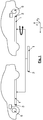
- Fig. 1 schematically the arrangement of a drive battery in a first motor vehicle with front-wheel drive (left) and in a second motor vehicle with rear-wheel drive (right) shown.
- the drive battery points a battery housing 1 and is designed as a flat accumulator with a rectangular plan, which is arranged in the region of a subfloor of the motor vehicle. At one end face of the drive battery, this has at least one, preferably electrical, terminal 3. This consists of a positive and a negative terminal pole of the drive battery.
- the connection 3 may additionally or alternatively have connections for connecting the battery to a cooling and / or heating system of the vehicle, in particular adjacent or combined with the electrical connections.
- the vehicle with front-wheel drive comprises an electric drive motor 6 in the front of the vehicle.
- the electrical connection 3 of the drive battery is arranged on an end face of the battery housing 1, which faces the electric drive motor 6, so that only short connecting lines between the drive battery and the drive motor 6 are required ,
- the vehicle in the right figure of the Fig. 1 has an electric drive motor 6 in the rear of the vehicle.
- the drive battery according to the invention is compared to the installation position in the front-wheel drive vehicle rotated by 180 degrees about a vertical axis, so that the electrical connection 3 of the drive battery is arranged here on the rear end of the battery case 1 and the necessary electrical connection lines are short again.
- Is shown in Fig. 1 also the vehicle coordinate system used in the present specification with the longitudinal direction x, transverse direction y and vertical direction z.
- the drive battery according to the invention comprises a plurality of cross member 4 and longitudinal member 5 in the battery case 1, to reinforce the drive battery in installation position in the vehicle transverse direction y or in the vehicle longitudinal direction x.
- All cross members 4 are arranged symmetrically with respect to a rotation of the drive battery about a vertical axis z by 180 degrees, so that the cross member 4 come to rest after such a rotation at the same positions in the vehicle longitudinal direction x, as before rotation.
- all the longitudinal members 5 are arranged symmetrically with respect to a rotation of the drive battery about a vertical axis z by 180 degrees, so that the longitudinal beams 5 come to rest after such a rotation at the same positions in the vehicle transverse direction y, as before rotation.
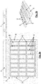
- Fig. 2a shows such a drive battery according to the invention from above, from the front and from the side, or in Fig. 2b three-dimensional, with an attached battery cover 7, which is part of the battery case 1 and, for example, from above or below can be removable.
- Fig. 3a and 3b show the same views of the same drive battery as Fig. 2a and 2b but without battery cover 7, so that the battery cover 7 is removed or hidden.
- the battery housing 1 has a flange surface with screwing points 8, for screwing to the shell of the vehicle.
- Cross member 4 and longitudinal beams 5 together form an approximately regular or regular, rectangular grid, with each other approximately the same or equal distances between the cross member 4 to each other in the vehicle longitudinal direction x on the one hand and with approximately the same or equal distances between the longitudinal beams 5 in the vehicle transverse direction y.
- the cross member 4 are arranged symmetrically spaced from the center of the drive battery in the longitudinal direction, so that the cross member left and right of the central axis are each equidistant from this.
- the side members are analogously arranged symmetrically to the center of the drive battery in the transverse direction. The longitudinal members are therefore on both sides of the horizontal center axis shown in the longitudinal direction each equidistant from this.
- the electrical connection 3 is arranged on an end face of the battery housing 1, for example in the form of one or two connection plugs or connection terminals for the two battery poles. Near the electrical terminal 3 and / or on the front side of the battery case 1, even if this has no electrical connection because the transmission of energy is, for example, inductively, can also be a connection for a cooling system, in particular for a cooling circuit and / or heating circuit of the battery his.
- the battery modules 2 are arranged in intermediate spaces between the cross members 4 and between the longitudinal members 5. Battery modules 2 and cross member 4 and side members 5 are largely arranged in the same vertical height.
- Fig. 4 shows the drive battery according to Fig. 3a Seen from above two times, in the upper view, the load paths on the cross member 4 are shown as arrows and in the lower illustration, the load paths on the side members 5, on the same drive battery, are located.
- the vehicle in which the illustrated drive batteries are received preferably at the ends of the cross member and / or side members, ie at the positions of the cross member or side members which remain in rotation by 180 degrees, also reinforcing structures, such as cross member and side member on, so that the illustrated load paths are deliberately continued in the vehicle to absorb or dissipate the forces.
- Fig. 5 again schematically shows a drive battery according to Fig. 3a from above, in the installed position in a vehicle with front-wheel drive in the upper view and in a vehicle with rear-wheel drive in the illustration below. Due to the symmetrical uniform distribution of the cross member 4, the same positions for the cross member 4 are achieved upon rotation of the drive battery suitable for the respective drive concept - represented by dashed lines - and thus achieved that vehicles with different drive concepts (front-wheel drive, rear wheel drive or four-wheel drive) the same Show side crash behavior.
Landscapes
- Engineering & Computer Science (AREA)
- Chemical & Material Sciences (AREA)
- General Chemical & Material Sciences (AREA)
- Electrochemistry (AREA)
- Chemical Kinetics & Catalysis (AREA)
- Mechanical Engineering (AREA)
- Transportation (AREA)
- Life Sciences & Earth Sciences (AREA)
- Power Engineering (AREA)
- Sustainable Energy (AREA)
- Sustainable Development (AREA)
- Aviation & Aerospace Engineering (AREA)
- Combustion & Propulsion (AREA)
- Arrangement Or Mounting Of Propulsion Units For Vehicles (AREA)
- Electric Propulsion And Braking For Vehicles (AREA)
Abstract
Description
- Die vorliegende Erfindung betrifft eine Antriebsbatterie für ein Kraftfahrzeug und eine Gruppe von Kraftfahrzeugen, umfassend zumindest ein erstes Kraftfahrzeug und zumindest ein zweites Kraftfahrzeug, wobei das erste und das zweite Kraftfahrzeug jeweils eine solche Antriebsbatterie umfassen.
- Antriebsbatterien für Kraftfahrzeuge sind seit einiger Zeit bekannt und werden in elektrisch angetriebenen Fahrzeugen, wie Elektro- und Hybridfahrzeugen eingesetzt. Derartige Antriebsbatterien sind für größere Leistungen ausgebildet und werden daher durch sogenannte "Hochvoltbatterien" gebildet. Üblicherweise umfassen solche Antriebsbatterien eine größere Anzahl von Batteriemodulen, die miteinander verschaltet sind und an einem gemeinsamen elektrischen Anschluss der Antriebsbatterie die erforderliche hohe Spannung abgeben können.
- Solche Antriebsbatterien benötigen üblicherweise einen relativ großen Bauraum und werden beispielsweise als Flachbatterien im Bereich eines Unterbodens eines Kraftfahrzeuges verbaut.
- Zur Erhöhung der Sicherheit, insbesondere bei einem Unfall des Kraftfahrzeuges, ist es bekannt Verstärkungen rund um Antriebsbatterien in einem Fahrzeug anzuordnen, oder auch innerhalb der Antriebsbatterien selbst.
- Kraftfahrzeuge werden heutzutage auch oft in unterschiedlichen Ausstattungsvarianten und insbesondere mit unterschiedlichen Antriebsvarianten auf einer gemeinsamen Fahrzeugplattform angeboten. So kann ein bestimmter Fahrzeugtyp beispielsweise mit Frontantrieb und mit Heckantrieb angeboten werden.
- Für unterschiedliche Antriebsvarianten müssen üblicherweise unterschiedliche Antriebsbatterien verbaut werden und/oder es müssen zusätzliche elektrische Leitungen bzw. Heiz-/ oder Kühlleitungen verlegt werden um von der Position eines elektrischen Anschlusses oder Heiz-/Kühlanschlusses der Antriebsbatterie zum Antrieb zu gelangen. Berechnungen zur Fahrzeugsicherheit müssen für jede Antriebsanordnung und insbesondere für jede Lage von Versteifungen des Kraftfahrzeuges erneut durchgeführt werden.
- Es ist eine Aufgabe der Erfindung, eine Antriebsbatterie für ein Kraftfahrzeug und eine Gruppe von Kraftfahrzeugen, umfassend zumindest ein erstes Kraftfahrzeug und zumindest ein zweites Kraftfahrzeug, wobei das erste und das zweite Kraftfahrzeug jeweils eine solche Antriebsbatterie umfassen, anzugeben, wobei die Antriebsbatterie für unterschiedliche Antriebsvarianten optimiert ausgebildet ist und dabei keine erneuten Berechnungen zur Fahrzeugsicherheit erforderlich sind.
- Die Lösung der Aufgabe erfolgt durch eine Antriebsbatterie für ein Kraftfahrzeug, umfassend ein Batteriegehäuse, mehrere Batteriemodule im Batteriegehäuse, einen Anschluss der Antriebsbatterie und zumindest einen, bevorzugt mehrere Querträger im Batteriegehäuse zur Verstärkung der Antriebsbatterie in Einbaulage in Fahrzeugquerrichtung, wobei die Gesamtheit der Querträger symmetrisch gegenüber einer Rotation der Antriebsbatterie um eine vertikale Achse um 180 Grad angeordnet ist, so dass die Querträger nach einer derartigen Rotation an den selben Positionen in Fahrzeuglängsrichtung zu liegen kommen, wie vor der Rotation.
- Erfindungsgemäß weist eine Antriebsbatterie in einem Batteriegehäuse zumindest einen, bevorzugt aber zumindest zwei, besonders bevorzugt mehr als zwei Querträger zur Versteifung auf, die, in vorgesehener Einbaulage der Antriebsbatterie gesehen, in einer Fahrzeugquerrichtung verlaufen.
- Bevorzugt hat die Antriebsbatterie in Draufsicht im Wesentlichen eine rechteckige, beispielsweise quadratische Form und die Querträger verlaufen parallel zur kürzeren Seite des Rechteckes, von einer Längsseite zur gegenüberliegenden Längsseite des Rechteckes.
- Die Querträger sind erfindungsgemäß so in der Batterie angeordnet, dass, nach einer Rotation der Antriebsbatterie um eine vertikale Achse um 180 Grad, also nach einer Drehung der im Fahrzeug vorne liegenden Seite der Antriebsbatterie nach hinten und umgekehrt, die Querträger an den selben Positionen in Fahrzeuglängsrichtung zu liegen kommen, wie vor dieser Rotation. Dabei muss natürlich nicht jeder einzelne Querträger wieder an der selben Position wie vor der Drehung liegen, sondern es wird für die meisten Querträger ein anderer Querträger an derjenigen Position in Fahrzeuglängsrichtung zu liegen kommen, an welcher der Querträger sich vor der Rotation befand. Lediglich ein in Längsrichtung mittig angeordneter Querträger wird nach der Drehung selbst an der selben Position in Längsrichtung zu liegen kommen.
- Bei einer erfindungsgemäßen Antriebsbatterie mit nur einem Querträger, liegt dieser daher mittig in Längsrichtung.
- Vorzugsweise hat die Antriebsbatterie aber mehrere Querträger. Diese sind vorzugsweise jeweils in gleichen Abständen zu beiden Seiten von der Mitte des Batteriegehäuses, in Fahrzeuglängsrichtung, entfernt angeordnet.
- Durch diese Anordnung der Querträger der Antriebsbatterie kann die selbe Antriebsbatterie in einem Fahrzeug mit Heckantrieb und einem Fahrzeug mit Frontantrieb verwendet werden und daher das gleiche Bauteil in höherer Stückzahl produziert werden. Im Fahrzeug mit Heckantrieb kann die Batterie im Vergleich zu einem Fahrzeug mit Frontantrieb um 180 Grad gedreht angeordnet werden, so dass der Anschluss der Batterie, insbesondere ein elektrischer Anschluss und/oder ein Heizanschluss und/oder ein Kühlanschluss, in beiden Antriebsvarianten nur wenig entfernt vom Antrieb des Fahrzeuges zu liegen kommt und nur kurze Verbindungsleitungen benötigt werden. Da dabei die Querträger der Antriebsbatterie bei beiden Antriebsvarianten an den selben Positionen zu liegen kommen, ist eine erneute Berechnung der Eigenschaften, insbesondere des Unfallverhaltens der lastaufnehmenden Versteifungen nicht erforderlich.
- Bevorzugt sind alle Querträger in regelmäßigen Abständen in Fahrzeuglängsrichtung im Batteriegehäuse angeordnet.
- Besonders bevorzugt umfasst die Antriebsbatterie zusätzlich zumindest einen, bevorzugt mehrere Längsträger im Batteriegehäuse zur Verstärkung der Antriebsbatterie in Einbaulage in Fahrzeuglängsrichtung, wobei die Gesamtheit der Längsträger symmetrisch gegenüber einer Rotation der Antriebsbatterie um eine vertikale Achse um 180 Grad angeordnet ist, so dass die Längsträger nach einer derartigen Rotation an den selben Positionen in Fahrzeugquerrichtung zu liegen kommen, wie vor der Rotation. Analog zu den Querträgern können auch Längsträger daher so im Batteriegehäuse angeordnet sein, dass die Versteifungscharakteristik bei Drehung der Batterie um 180 Grad nicht geändert wird.
- Alle Längsträger sind dann bevorzugt in regelmäßigen Abständen in Fahrzeugquerrichtung im Batteriegehäuse angeordnet.
- Vorzugsweise bilden die Querträger und die Längsträger zusammen ein regelmäßiges, rechtwinkeliges Gitter, mit zueinander gleichen Abständen in Fahrzeuglängsrichtung einerseits und mit zueinander gleichen Abständen in Fahrzeugquerrichtung andererseits.
- Bevorzugt ist der Anschluss, insbesondere ein elektrischer Anschluss, an einer Stirnseite des Batteriegehäuses angeordnet. Bevorzugt ist zusätzlich auch ein Kühlanschluss an der selben Stirnseite des Batteriegehäuses angeordnet wie der elektrische Anschluss. Durch das Drehen der Batterie um 180 Grad kommen die jeweiligen Anschlüsse dadurch nahe der Frontseite bzw. der Heckseite des Fahrzeuges zu liegen.
- Die Batteriemodule sind bevorzugt in Zwischenräumen zwischen den Querträgern und gegebenenfalls zwischen den Längsträgern angeordnet.
- Die Lösung der Aufgabe erfolgt erfindungsgemäß auch durch eine Gruppe von Kraftfahrzeugen, umfassend zumindest ein erstes Kraftfahrzeug, wobei das erste Kraftfahrzeug mit einem Frontantrieb ausgestattet ist und zumindest ein zweites Kraftfahrzeug, wobei das zweite Kraftfahrzeug mit einem Heckantrieb ausgestattet ist, wobei das erste und das zweite Kraftfahrzeug jeweils eine gleichartige Antriebsbatterie, wie zuvor beschrieben, umfassen, wobei die Antriebsbatterie im zweiten Kraftfahrzeug um eine vertikale Achse um 180 Grad gedreht ist gegenüber der Anordnung der Antriebsbatterie im ersten Kraftfahrzeug. Die Querträger im zweiten Kraftfahrzeug liegen dann an den selben Positionen in Fahrzeuglängsrichtung, wie im ersten Kraftfahrzeug.
- Vorzugsweise ist im ersten Kraftfahrzeug mit Frontantrieb der Anschluss der Antriebsbatterie näher der Front des Fahrzeuges angeordnet, insbesondere an einer vorderen Seitenwand des Batteriegehäuses und ist im zweiten Kraftfahrzeug mit Heckantrieb der Anschluss der Antriebsbatterie näher dem Heck des Fahrzeuges angeordnet, insbesondere an einer hinteren Seitenwand des Batteriegehäuses, so dass der Anschluss, insbesondere ein elektrischer Anschluss und/oder ein Heiz- und/oder Kühlanschluss der Antriebsbatterie, jeweils nahe des Antriebs angeordnet ist.
- Der "Anschluss" ist nicht auf eine einzige elektrische und /oder mechanische Kontaktierung oder bloß einen Stecker eingeschränkt, sondern kann beispielsweise einen oder zwei Anschlussstecker oder Anschlussklemmen für die beiden Batteriepole und /oder für den Kühlkreislauf/Heizkreislauf der Batterie umfassen.
- Die Erfindung wird im Folgenden beispielhaft unter Bezugnahme auf die Zeichnungen beschrieben.
- Fig. 1
- ist eine schematische Schnittansicht einer erfindungsgemäßen Gruppe von Kraftfahrzeugen, umfassend ein erstes Kraftfahrzeug mit Frontantrieb und ein zweites Kraftfahrzeug mit Heckantrieb, die jeweils eine erfindungsgemäße Antriebsbatterie aufweisen.
- Fig. 2a
- sind Ansichten die eine erfindungsgemäße Antriebsbatterie von oben, von vorne und von der Seite zeigen.
- Fig. 2b
- ist eine dreidimensionale Ansicht der Antriebsbatterie gemäß
Fig. 2a . - Fig. 3a
- sind Ansichten die eine erfindungsgemäße Antriebsbatterie von oben, von vorne und von der Seite zeigen, entsprechend
Fig. 2a , jedoch ohne Batteriedeckel. - Fig. 3b
- ist eine dreidimensionale Ansicht der Antriebsbatterie gemäß
Fig. 3a . - Fig. 4
- ist eine Ansicht der Antriebsbatterie gemäß
Fig. 3a von oben, mit eingezeichneten Lastpfaden über die Querträger (oben) und über die Längsträger (unten). - Fig. 5
- ist eine schematische Ansicht der Antriebsbatterie gemäß
Fig. 3a von unten, in Einbaulage in einem Fahrzeug mit Frontantrieb (oben) und in einem Fahrzeug mit Heckantrieb (unten). - In
Fig. 1 ist schematisch die Anordnung einer Antriebsbatterie in einem ersten Kraftfahrzeug mit Frontantrieb (links) und in einem zweiten Kraftfahrzeug mit Heckantrieb (rechts) dargestellt. Die Antriebsbatterie weist ein Batteriegehäuse 1 auf und ist als Flachspeicher mit rechteckigem Grundriss ausgebildet, der im Bereich eines Unterbodens des Kraftfahrzeuges angeordnet ist. An einer Stirnseite der Antriebsbatterie weist diese zumindest einen, vorzugsweise elektrischen, Anschluss 3 auf. Dieser besteht aus einem positiven und einem negativen Anschlusspol der Antriebsbatterie. Der Anschluss 3 kann zusätzlich oder alternativ Anschlüsse zur Verbindung der Batterie mit einem Kühl- und / oder Heizsystem des Fahrzeuges aufweisen, insbesondere benachbart oder kombiniert mit den elektrischen Anschlüssen. Das Fahrzeug mit Frontantrieb umfasst in der Front des Fahrzeuges einen elektrischen Antriebsmotor 6. Der elektrische Anschluss 3 der Antriebsbatterie ist an einer Stirnseite des Batteriegehäuses 1 angeordnet, der dem elektrischen Antriebsmotor 6 zugewandt ist, so dass nur kurze Verbindungsleitungen zwischen Antriebsbatterie und Antriebsmotor 6 erforderlich sind. - Das Fahrzeug in der rechten Abbildung der
Fig. 1 weist einen elektrischen Antriebsmotor 6 im Heck des Fahrzeuges auf. Hierzu ist erfindungsgemäß die Antriebsbatterie im Vergleich zur Einbaulage im Frontgetriebenen Fahrzeug um eine vertikale Achse um 180 Grad gedreht, so dass der elektrische Anschluss 3 der Antriebsbatterie hier an der hinteren Stirnseite des Batteriegehäuses 1 angeordnet ist und die erforderlichen elektrischen Verbindungsleitungen wieder kurz ausgebildet sind. - Dargestellt ist in
Fig. 1 auch das in der vorliegenden Schrift verwendete Fahrzeugkoordinatensystem mit Längsrichtung x, Querrichtung y und vertikaler Richtung z. - Wie in den
Fig. 2 bis 5 näher dargestellt, weist die Antriebsbatterie erfindungsgemäß mehrere Querträger 4 und Längsträger 5 im Batteriegehäuse 1 auf, zur Verstärkung der Antriebsbatterie in Einbaulage in Fahrzeugquerrichtung y bzw. in Fahrzeuglängsrichtung x. Alle Querträger 4 sind symmetrisch gegenüber einer Rotation der Antriebsbatterie um eine vertikale Achse z um 180 Grad angeordnet, so dass die Querträger 4 nach einer derartigen Rotation an den selben Positionen in Fahrzeuglängsrichtung x zu liegen kommen, wie vor der Rotation. - Zusätzlich sind auch alle Längsträger 5 symmetrisch gegenüber einer Rotation der Antriebsbatterie um eine vertikale Achse z um 180 Grad angeordnet, so dass die Längsträger 5 nach einer derartigen Rotation an den selben Positionen in Fahrzeugquerrichtung y zu liegen kommen, wie vor der Rotation.
- Daher bleiben bei Einbau einer derartigen Antriebsbatterie in den beiden in
Fig. 1 links bzw. rechts dargestellten zu einender gedrehten Lagen, die Positionen der Querträger 4 sowie auch der Längsträger 5 unverändert. Die Lastpfade an den Quer- und Längsträgern 4, 5, eingezeichnet als Pfeile inFig. 4 , bleiben bestehen (Fig. 5 ). Die selbe Antriebsbatterie kann in beiden Fahrzeugvarianten verwendet werden, ohne Neuberechnung der mechanischen Eigenschaften der Verstärkungsstrukturen insbesondere des Unfallverhaltens der Verstärkungsstrukturen der Antriebsbatterie. -
Fig. 2a zeigt eine derartige erfindungsgemäße Antriebsbatterie von oben, von vorne und von der Seite, bzw. inFig. 2b dreidimensional, mit einem aufgesetzten Batteriedeckel 7, der Teil des Batteriegehäuses 1 ist und beispielsweise von oben oder unten abnehmbar sein kann. -
Fig. 3a und 3b zeigen die selben Ansichten der selben Antriebsbatterie wieFig. 2a und 2b , jedoch ohne Batteriedeckel 7, wobei also der Batteriedeckel 7 abgenommen oder ausgeblendet ist. - Das Batteriegehäuse 1 weist eine Flanschfläche mit Verschraubungspunkten 8, zur Verschraubung mit dem Rohbau des Fahrzeuges auf.
- Querträger 4 und Längsträger 5 bilden zusammen ein annähernd regemäßiges bzw. regelmäßiges, rechtwinkeliges Gitter, mit zueinander annähernd gleichen bzw. gleichen Abständen der Querträger 4 zueinander in Fahrzeuglängsrichtung x einerseits und mit zueinander annähernd gleichen bzw. gleichen Abständen der Längsträger 5 in Fahrzeugquerrichtung y andererseits. Ebenso sind die Querträger 4 symmetrisch zur Mitte der Antriebsbatterie in Längsrichtung beabstandet angeordnet, so dass die Querträger links und rechts der Mittelachse jeweils gleich weit von dieser entfernt sind. Die Längsträger sind analog symmetrisch zur Mitte der Antriebsbatterie in Querrichtung beabstandet angeordnet. Die Längsträger sind daher zu beiden Seiten der horizontal dargestellten Mittelachse in Längsrichtung jeweils gleich weit von dieser entfernt.
- Der elektrische Anschluss 3 ist an einer Stirnseite des Batteriegehäuses 1 angeordnet, beispielsweise in Form eines oder zweier Anschlussstecker oder Anschlussklemmen für die beiden Batteriepole. Nahe des elektrischen Anschlusses 3 und / oder an der Stirnseite des Batteriegehäuses 1, auch falls dieses keinen elektrischen Anschluss aufweist weil die Übertragung der Energie beispielsweise induktiv erfolgt, kann auch ein Anschluss für ein Kühlsystem, insbesondere für einen Kühlkreislauf und / oder Heizkreislauf der Batterie angeordnet sein.
- Die Batteriemodule 2 sind in Zwischenräumen zwischen den Querträgern 4 und zwischen den Längsträgern 5 angeordnet. Batteriemodule 2 und Querträger 4 sowie Längsträger 5 sind weitgehend in der selben vertikalen Höhe angeordnet.
-
Fig. 4 zeigt die Antriebsbatterie gemäßFig. 3a von oben gesehen zwei mal, wobei in der oberen Darstellung die Lastpfaden über die Querträger 4 als Pfeile eingezeichnet sind und in der unteren Darstellung die Lastpfade über die Längsträger 5, an der selben Antriebsbatterie, eingezeichnet sind. Das Fahrzeug, in welche die dargestellten Antriebsbatterien aufgenommen sind, weist bevorzugt an den Enden der Querträger und/oder Längsträger, also an den Positionen der Querträger bzw. Längsträger die bei Rotation um 180 Grad erhalten bleiben, ebenfalls Verstärkungsstrukturen, wie zum Beispiel Querträger und Längsträger auf, so dass die dargestellten Lastpfade gezielt im Fahrzeug weiter geführt werden um die auftretenden Kräfte aufzunehmen bzw. abzuleiten. -
Fig. 5 zeigt wieder schematisch eine Antriebsbatterie gemäßFig. 3a von oben, und zwar in Einbaulage in einem Fahrzeug mit Frontantrieb in der oberen Darstellung und in einem Fahrzeug mit Heckantrieb in der Darstellung unten. Durch die symmetrische gleichmäßige Verteilung der Querträger 4, werden bei Drehung der Antriebsbatterie passend zum jeweiligen Antriebskonzept, gleiche Positionen für die Querträger 4 erreicht - dargestellt durch gestrichelte Linien - und somit erreicht, dass Fahrzeuge mit unterschiedlichen Antriebskonzepten (Frontantrieb, Heckantrieb oder Allradantrieb) das gleiche Seitencrash-Verhalten zeigen. -
- 1
- Batteriegehäuse
- 2
- Batteriemodul
- 3
- Anschluss bzw. Anschlüsse für Elektrik, Kühlung etc.
- 4
- Querträger
- 5
- Längsträger
- 6
- Antriebsmotor
- 7
- Batteriedeckel
- 8
- Verschraubungspunkt
- x
- Fahrzeuglängsrichtung
- y
- Fahrzeugquerrichtung
- z
- vertikale Achse
Claims (8)
- Antriebsbatterie für ein Kraftfahrzeug, umfassend ein Batteriegehäuse (1), mehrere Batteriemodule (2) im Batteriegehäuse (1), einen Anschluss (3) der Antriebsbatterie und zumindest einen, bevorzugt mehrere Querträger (4) im Batteriegehäuse (1) zur Verstärkung der Antriebsbatterie in Einbaulage in Fahrzeugquerrichtung (y),
dadurch gekennzeichnet, dass die Gesamtheit der Querträger (4) symmetrisch gegenüber einer Rotation der Antriebsbatterie um eine vertikale Achse (z) um 180 Grad angeordnet ist, so dass die Querträger (4) nach einer derartigen Rotation an den selben Positionen in Fahrzeuglängsrichtung (x) zu liegen kommen, wie vor der Rotation. - Antriebsbatterie nach Anspruch 1,
dadurch gekennzeichnet, dass alle Querträger (4) in regelmäßigen Abständen in Fahrzeuglängsrichtung (x) im Batteriegehäuse (1) angeordnet sind. - Antriebsbatterie nach zumindest einem der vorhergehenden Ansprüche,
dadurch gekennzeichnet, dass die Antriebsbatterie zumindest einen, bevorzugt mehrere Längsträger (5) im Batteriegehäuse (1) zur Verstärkung der Antriebsbatterie in Einbaulage in Fahrzeuglängsrichtung (x) umfasst, wobei die Gesamtheit der Längsträger (5) symmetrisch gegenüber einer Rotation der Antriebsbatterie um eine vertikale Achse um 180 Grad angeordnet ist, so dass die Längsträger (5) nach einer derartigen Rotation an den selben Positionen in Fahrzeugquerrichtung (y) zu liegen kommen, wie vor der Rotation. - Antriebsbatterie nach zumindest einem der vorhergehenden Ansprüche,
dadurch gekennzeichnet, dass alle Längsträger (5) in regelmäßigen Abständen in Fahrzeugquerrichtung (y) im Batteriegehäuse (1) angeordnet sind. - Antriebsbatterie nach zumindest einem der vorhergehenden Ansprüche,
dadurch gekennzeichnet, dass die Querträger (4) und die Längsträger (5) zusammen ein regelmäßiges, rechtwinkeliges Gitter bilden, mit zueinander gleichen Abständen in Fahrzeuglängsrichtung (x) einerseits und mit zueinander gleichen Abständen in Fahrzeugquerrichtung (y) andererseits. - Antriebsbatterie nach zumindest einem der vorhergehenden Ansprüche,
dadurch gekennzeichnet, dass der Anschluss (3) einen elektrischen Anschluss bildet und an einer Stirnseite des Batteriegehäuses (1) angeordnet ist und bevorzugt auch ein Kühlanschluss an der selben Stirnseite des Batteriegehäuses (1) angeordnet ist. - Antriebsbatterie nach zumindest einem der vorhergehenden Ansprüche,
dadurch gekennzeichnet, dass die Batteriemodule (2) in Zwischenräumen zwischen den Querträgern (4) und gegebenenfalls zwischen den Längsträgern (5) angeordnet sind. - Gruppe von Kraftfahrzeugen, umfassend zumindest ein erstes Kraftfahrzeug, wobei das erste Kraftfahrzeug mit einem Frontantrieb ausgestattet ist und zumindest ein zweites Kraftfahrzeug, wobei das zweite Kraftfahrzeug mit einem Heckantrieb ausgestattet ist,
dadurch gekennzeichnet, dass das erste und das zweite Kraftfahrzeug jeweils eine gleichartige Antriebsbatterie nach zumindest einem der vorhergehenden Ansprüche umfassen, wobei die Antriebsbatterie im zweiten Kraftfahrzeug um eine vertikale Achse um 180 Grad gedreht ist, gegenüber der Anordnung der Antriebsbatterie im ersten Kraftfahrzeug, so dass die Querträger (4) im zweiten Kraftfahrzeug an den selben Positionen in Fahrzeuglängsrichtung (x) liegen, wie im ersten Kraftfahrzeug.
Priority Applications (3)
| Application Number | Priority Date | Filing Date | Title |
|---|---|---|---|
| EP18157595.2A EP3528305B1 (de) | 2018-02-20 | 2018-02-20 | Verwendung von antriebsbatterien in kraftfahrzeugen |
| US16/256,011 US20190255928A1 (en) | 2018-02-20 | 2019-01-24 | Traction battery |
| CN201910125479.4A CN110182035B (zh) | 2018-02-20 | 2019-02-20 | 牵引电池 |
Applications Claiming Priority (1)
| Application Number | Priority Date | Filing Date | Title |
|---|---|---|---|
| EP18157595.2A EP3528305B1 (de) | 2018-02-20 | 2018-02-20 | Verwendung von antriebsbatterien in kraftfahrzeugen |
Publications (2)
| Publication Number | Publication Date |
|---|---|
| EP3528305A1 true EP3528305A1 (de) | 2019-08-21 |
| EP3528305B1 EP3528305B1 (de) | 2023-01-04 |
Family
ID=61249561
Family Applications (1)
| Application Number | Title | Priority Date | Filing Date |
|---|---|---|---|
| EP18157595.2A Active EP3528305B1 (de) | 2018-02-20 | 2018-02-20 | Verwendung von antriebsbatterien in kraftfahrzeugen |
Country Status (3)
| Country | Link |
|---|---|
| US (1) | US20190255928A1 (de) |
| EP (1) | EP3528305B1 (de) |
| CN (1) | CN110182035B (de) |
Cited By (2)
| Publication number | Priority date | Publication date | Assignee | Title |
|---|---|---|---|---|
| EP4220832A4 (de) * | 2021-09-16 | 2024-05-29 | LG Energy Solution, Ltd. | Batteriepack und vorrichtung damit |
| DE102024109067B3 (de) * | 2024-03-28 | 2025-07-10 | Bayerische Motoren Werke Aktiengesellschaft | Traktionsbatterie für ein Elektrofahrzeug, Elektrofahrzeug mit einer Traktionsbatterie, Verfahren zum Herstellen eines Elektrofahrzeugs sowie Baukastensystem zum Herstellen mehrerer Bauvarianten eines Elektrofahrzeugs |
Families Citing this family (9)
| Publication number | Priority date | Publication date | Assignee | Title |
|---|---|---|---|---|
| JP6791045B2 (ja) * | 2017-07-18 | 2020-11-25 | トヨタ自動車株式会社 | 車体前部構造 |
| US10864810B2 (en) * | 2019-04-25 | 2020-12-15 | Fca Us Llc | Bowstring-truss battery cradle system |
| WO2022115134A1 (en) | 2020-11-30 | 2022-06-02 | Nikola Corporation | High voltage electrical system for battery electric vehicle |
| US11124076B1 (en) | 2020-11-30 | 2021-09-21 | Nikola Corporation | Electric vehicle battery frame assembly |
| US11820241B2 (en) | 2020-11-30 | 2023-11-21 | Nikola Corporation | Battery pack assembly |
| US12291112B2 (en) | 2020-11-30 | 2025-05-06 | Nikola Corporation | High voltage battery conditioning for battery electric vehicle |
| CN115991090A (zh) * | 2023-01-09 | 2023-04-21 | 阿尔特汽车技术股份有限公司 | 适配不同驱动形式的电池包及车辆 |
| FR3158267B1 (fr) * | 2024-01-17 | 2025-11-28 | Stellantis Auto Sas | Vehicule automobile electrique ou hybride comportant un bac de batterie comprenant un cadre comportant au moins une traverse configurée pour pivoter |
| EP4631773A1 (de) * | 2024-04-08 | 2025-10-15 | MAGNA STEYR Fahrzeugtechnik GmbH & Co KG | Kraftfahrzeug mit einer hochvoltbatterie |
Citations (3)
| Publication number | Priority date | Publication date | Assignee | Title |
|---|---|---|---|---|
| US20170170438A1 (en) * | 2015-12-14 | 2017-06-15 | General Electric Company | Battery packaging system and method for a vehicle |
| DE102016209853A1 (de) * | 2016-06-06 | 2017-12-21 | Volkswagen Aktiengesellschaft | Unterschale für ein Batteriegehäuse und Traktionsbatterie für ein Kraftfahrzeug |
| US20180029493A1 (en) * | 2016-07-29 | 2018-02-01 | Honda Motor Co., Ltd. | Battery pack for electric vehicle |
Family Cites Families (12)
| Publication number | Priority date | Publication date | Assignee | Title |
|---|---|---|---|---|
| US6085854A (en) * | 1994-12-13 | 2000-07-11 | Nissan Motor Co., Ltd. | Battery frame structure for electric motorcar |
| JP4845676B2 (ja) * | 2006-10-31 | 2011-12-28 | 三洋電機株式会社 | 電動車両とこれに搭載される電源装置 |
| JP4420018B2 (ja) * | 2006-12-28 | 2010-02-24 | 三菱自動車工業株式会社 | 電気自動車のバッテリ搭載構造 |
| JP4420017B2 (ja) * | 2006-12-28 | 2010-02-24 | 三菱自動車工業株式会社 | 電気自動車のバッテリ搭載構造 |
| JP4434213B2 (ja) * | 2007-01-26 | 2010-03-17 | 三菱自動車工業株式会社 | 電気自動車のバッテリ搭載構造 |
| JP5071538B2 (ja) * | 2010-09-03 | 2012-11-14 | トヨタ自動車株式会社 | 車両用電池搭載構造 |
| CN202174924U (zh) * | 2011-07-29 | 2012-03-28 | 比亚迪股份有限公司 | 一种车辆动力电池的安装结构 |
| JP5790365B2 (ja) * | 2011-09-20 | 2015-10-07 | トヨタ自動車株式会社 | 車両用バッテリ搭載構造 |
| KR101315741B1 (ko) * | 2012-03-23 | 2013-10-10 | 현대자동차주식회사 | 치수안정성이 우수한 전기자동차용 배터리 팩 케이스 어셈블리와 그 제조 방법 |
| CN105810861A (zh) * | 2014-12-29 | 2016-07-27 | 中国科学院深圳先进技术研究院 | 一种电动汽车电池包 |
| DE102015111749A1 (de) * | 2015-07-20 | 2017-01-26 | Dr. Ing. H.C. F. Porsche Aktiengesellschaft | Batterieeinrichtung und Verfahren |
| JP6520808B2 (ja) * | 2016-04-21 | 2019-05-29 | トヨタ自動車株式会社 | 車両のバッテリ搭載構造 |
-
2018
- 2018-02-20 EP EP18157595.2A patent/EP3528305B1/de active Active
-
2019
- 2019-01-24 US US16/256,011 patent/US20190255928A1/en not_active Abandoned
- 2019-02-20 CN CN201910125479.4A patent/CN110182035B/zh active Active
Patent Citations (3)
| Publication number | Priority date | Publication date | Assignee | Title |
|---|---|---|---|---|
| US20170170438A1 (en) * | 2015-12-14 | 2017-06-15 | General Electric Company | Battery packaging system and method for a vehicle |
| DE102016209853A1 (de) * | 2016-06-06 | 2017-12-21 | Volkswagen Aktiengesellschaft | Unterschale für ein Batteriegehäuse und Traktionsbatterie für ein Kraftfahrzeug |
| US20180029493A1 (en) * | 2016-07-29 | 2018-02-01 | Honda Motor Co., Ltd. | Battery pack for electric vehicle |
Cited By (2)
| Publication number | Priority date | Publication date | Assignee | Title |
|---|---|---|---|---|
| EP4220832A4 (de) * | 2021-09-16 | 2024-05-29 | LG Energy Solution, Ltd. | Batteriepack und vorrichtung damit |
| DE102024109067B3 (de) * | 2024-03-28 | 2025-07-10 | Bayerische Motoren Werke Aktiengesellschaft | Traktionsbatterie für ein Elektrofahrzeug, Elektrofahrzeug mit einer Traktionsbatterie, Verfahren zum Herstellen eines Elektrofahrzeugs sowie Baukastensystem zum Herstellen mehrerer Bauvarianten eines Elektrofahrzeugs |
Also Published As
| Publication number | Publication date |
|---|---|
| CN110182035B (zh) | 2023-01-10 |
| EP3528305B1 (de) | 2023-01-04 |
| US20190255928A1 (en) | 2019-08-22 |
| CN110182035A (zh) | 2019-08-30 |
Similar Documents
| Publication | Publication Date | Title |
|---|---|---|
| EP3528305B1 (de) | Verwendung von antriebsbatterien in kraftfahrzeugen | |
| DE102017108383B4 (de) | Filter mit Leiterplatte und Stromschienen | |
| DE102013101323B4 (de) | Filterbauelement | |
| DE102010050841B4 (de) | Sammelschienenschaltungsstruktur und Anschlussblock | |
| DE102018212945A1 (de) | Leitermodul | |
| DE102011051627A1 (de) | Baukastensystem für eine Batterie | |
| DE102019126101A1 (de) | Anschlussblock für einen Motor und Verfahren zu dessen Herstellung | |
| DE102014010067A1 (de) | Spannungsgeschützt herstellbare Kraftfahrzeugbatterie | |
| DE102016204681A1 (de) | Batterie und Verfahren zur Herstellung einer Batterie | |
| DE102018205962A1 (de) | Traktionsbatterie für ein elektrisch oder teilelektrisch antreibbares Fahrzeug | |
| DE102014014925A1 (de) | Hochvoltverteiler für ein Hybrid- oder Elektrofahrzeug | |
| DE102017200479A1 (de) | Modulare energiespeichervorrichtung, herstellungsverfahren sowie fahrzeug | |
| DE102018207536A1 (de) | Hochvoltbatterie für ein Kraftfahrzeug und Kraftfahrzeug | |
| DE102019105584A1 (de) | Fahrzeug mit durch den rahmen verlegtem elektrischen verteilungssystem | |
| DE102014019433A1 (de) | Elektronikbaueinheit für einen Elektromotor eines Einzelradantriebs eines Kraftfahrzeugs, Einzelradantrieb sowie Kraftfahrzeug | |
| DE102019103413A1 (de) | Brennstoffzellenfahrzeug | |
| DE102011102200A1 (de) | Elektrisches System und Verfahren zur Verteilung elektrischer Energie | |
| EP4466750A1 (de) | Steckverbinder zum verbinden von hochvoltkomponenten | |
| WO2022238068A1 (de) | Hochvoltspeicher mit kleinteiliger zellverbinderanordnung | |
| DE102014014926A1 (de) | Anordnung aus mindestens zwei elektrischen Traktionsenergiespeichern | |
| DE102018209018A1 (de) | Hochvoltbordnetzanordnung für ein Kraftfahrzeug und Kraftfahrzeug | |
| EP4264799A1 (de) | Anschlusseinheit für einen stator, stator für eine elektrische maschine, statoranordnung, verfahren zur herstellung einer statoranordnung und elektrische maschine zum antreiben eines fahrzeugs | |
| DE112017006620T5 (de) | Leitfähiges Glied und leitfähiger Pfad unter Verwendung einer Mehrzahl von leitfähigen Gliedern | |
| DE102021202496A1 (de) | Verteilungssystem für ein Bordnetz sowie Versorgungsstrang für ein solches Verteilungssystem | |
| DE102016225291A1 (de) | Entkopplungselement zur Verbindung einer Leistungselektronik mit einer elektrischen Maschine |
Legal Events
| Date | Code | Title | Description |
|---|---|---|---|
| PUAI | Public reference made under article 153(3) epc to a published international application that has entered the european phase |
Free format text: ORIGINAL CODE: 0009012 |
|
| STAA | Information on the status of an ep patent application or granted ep patent |
Free format text: STATUS: THE APPLICATION HAS BEEN PUBLISHED |
|
| AK | Designated contracting states |
Kind code of ref document: A1 Designated state(s): AL AT BE BG CH CY CZ DE DK EE ES FI FR GB GR HR HU IE IS IT LI LT LU LV MC MK MT NL NO PL PT RO RS SE SI SK SM TR |
|
| AX | Request for extension of the european patent |
Extension state: BA ME |
|
| STAA | Information on the status of an ep patent application or granted ep patent |
Free format text: STATUS: REQUEST FOR EXAMINATION WAS MADE |
|
| 17P | Request for examination filed |
Effective date: 20200214 |
|
| RBV | Designated contracting states (corrected) |
Designated state(s): AL AT BE BG CH CY CZ DE DK EE ES FI FR GB GR HR HU IE IS IT LI LT LU LV MC MK MT NL NO PL PT RO RS SE SI SK SM TR |
|
| STAA | Information on the status of an ep patent application or granted ep patent |
Free format text: STATUS: EXAMINATION IS IN PROGRESS |
|
| 17Q | First examination report despatched |
Effective date: 20210527 |
|
| REG | Reference to a national code |
Ref country code: DE Ref legal event code: R079 Ref document number: 502018011345 Country of ref document: DE Free format text: PREVIOUS MAIN CLASS: H01M0002100000 Ipc: H01M0050249000 |
|
| RIC1 | Information provided on ipc code assigned before grant |
Ipc: B60L 50/64 20190101ALI20220721BHEP Ipc: H01M 50/233 20210101ALI20220721BHEP Ipc: H01M 50/249 20210101AFI20220721BHEP |
|
| GRAP | Despatch of communication of intention to grant a patent |
Free format text: ORIGINAL CODE: EPIDOSNIGR1 |
|
| STAA | Information on the status of an ep patent application or granted ep patent |
Free format text: STATUS: GRANT OF PATENT IS INTENDED |
|
| INTG | Intention to grant announced |
Effective date: 20220919 |
|
| RAP3 | Party data changed (applicant data changed or rights of an application transferred) |
Owner name: MAGNA STEYR FAHRZEUGTECHNIK GMBH & CO KG |
|
| GRAS | Grant fee paid |
Free format text: ORIGINAL CODE: EPIDOSNIGR3 |
|
| GRAA | (expected) grant |
Free format text: ORIGINAL CODE: 0009210 |
|
| STAA | Information on the status of an ep patent application or granted ep patent |
Free format text: STATUS: THE PATENT HAS BEEN GRANTED |
|
| AK | Designated contracting states |
Kind code of ref document: B1 Designated state(s): AL AT BE BG CH CY CZ DE DK EE ES FI FR GB GR HR HU IE IS IT LI LT LU LV MC MK MT NL NO PL PT RO RS SE SI SK SM TR |
|
| REG | Reference to a national code |
Ref country code: GB Ref legal event code: FG4D Free format text: NOT ENGLISH |
|
| REG | Reference to a national code |
Ref country code: DE Ref legal event code: R096 Ref document number: 502018011345 Country of ref document: DE |
|
| REG | Reference to a national code |
Ref country code: CH Ref legal event code: EP |
|
| REG | Reference to a national code |
Ref country code: AT Ref legal event code: REF Ref document number: 1542592 Country of ref document: AT Kind code of ref document: T Effective date: 20230115 |
|
| REG | Reference to a national code |
Ref country code: IE Ref legal event code: FG4D Free format text: LANGUAGE OF EP DOCUMENT: GERMAN |
|
| REG | Reference to a national code |
Ref country code: LT Ref legal event code: MG9D |
|
| REG | Reference to a national code |
Ref country code: NL Ref legal event code: MP Effective date: 20230104 |
|
| PG25 | Lapsed in a contracting state [announced via postgrant information from national office to epo] |
Ref country code: NL Free format text: LAPSE BECAUSE OF FAILURE TO SUBMIT A TRANSLATION OF THE DESCRIPTION OR TO PAY THE FEE WITHIN THE PRESCRIBED TIME-LIMIT Effective date: 20230104 |
|
| PG25 | Lapsed in a contracting state [announced via postgrant information from national office to epo] |
Ref country code: RS Free format text: LAPSE BECAUSE OF FAILURE TO SUBMIT A TRANSLATION OF THE DESCRIPTION OR TO PAY THE FEE WITHIN THE PRESCRIBED TIME-LIMIT Effective date: 20230104 Ref country code: PT Free format text: LAPSE BECAUSE OF FAILURE TO SUBMIT A TRANSLATION OF THE DESCRIPTION OR TO PAY THE FEE WITHIN THE PRESCRIBED TIME-LIMIT Effective date: 20230504 Ref country code: NO Free format text: LAPSE BECAUSE OF FAILURE TO SUBMIT A TRANSLATION OF THE DESCRIPTION OR TO PAY THE FEE WITHIN THE PRESCRIBED TIME-LIMIT Effective date: 20230404 Ref country code: LV Free format text: LAPSE BECAUSE OF FAILURE TO SUBMIT A TRANSLATION OF THE DESCRIPTION OR TO PAY THE FEE WITHIN THE PRESCRIBED TIME-LIMIT Effective date: 20230104 Ref country code: LT Free format text: LAPSE BECAUSE OF FAILURE TO SUBMIT A TRANSLATION OF THE DESCRIPTION OR TO PAY THE FEE WITHIN THE PRESCRIBED TIME-LIMIT Effective date: 20230104 Ref country code: HR Free format text: LAPSE BECAUSE OF FAILURE TO SUBMIT A TRANSLATION OF THE DESCRIPTION OR TO PAY THE FEE WITHIN THE PRESCRIBED TIME-LIMIT Effective date: 20230104 Ref country code: ES Free format text: LAPSE BECAUSE OF FAILURE TO SUBMIT A TRANSLATION OF THE DESCRIPTION OR TO PAY THE FEE WITHIN THE PRESCRIBED TIME-LIMIT Effective date: 20230104 |
|
| PG25 | Lapsed in a contracting state [announced via postgrant information from national office to epo] |
Ref country code: SE Free format text: LAPSE BECAUSE OF FAILURE TO SUBMIT A TRANSLATION OF THE DESCRIPTION OR TO PAY THE FEE WITHIN THE PRESCRIBED TIME-LIMIT Effective date: 20230104 Ref country code: PL Free format text: LAPSE BECAUSE OF FAILURE TO SUBMIT A TRANSLATION OF THE DESCRIPTION OR TO PAY THE FEE WITHIN THE PRESCRIBED TIME-LIMIT Effective date: 20230104 Ref country code: IS Free format text: LAPSE BECAUSE OF FAILURE TO SUBMIT A TRANSLATION OF THE DESCRIPTION OR TO PAY THE FEE WITHIN THE PRESCRIBED TIME-LIMIT Effective date: 20230504 Ref country code: GR Free format text: LAPSE BECAUSE OF FAILURE TO SUBMIT A TRANSLATION OF THE DESCRIPTION OR TO PAY THE FEE WITHIN THE PRESCRIBED TIME-LIMIT Effective date: 20230405 Ref country code: FI Free format text: LAPSE BECAUSE OF FAILURE TO SUBMIT A TRANSLATION OF THE DESCRIPTION OR TO PAY THE FEE WITHIN THE PRESCRIBED TIME-LIMIT Effective date: 20230104 |
|
| REG | Reference to a national code |
Ref country code: CH Ref legal event code: PL |
|
| REG | Reference to a national code |
Ref country code: DE Ref legal event code: R097 Ref document number: 502018011345 Country of ref document: DE |
|
| REG | Reference to a national code |
Ref country code: BE Ref legal event code: MM Effective date: 20230228 |
|
| PG25 | Lapsed in a contracting state [announced via postgrant information from national office to epo] |
Ref country code: SM Free format text: LAPSE BECAUSE OF FAILURE TO SUBMIT A TRANSLATION OF THE DESCRIPTION OR TO PAY THE FEE WITHIN THE PRESCRIBED TIME-LIMIT Effective date: 20230104 Ref country code: RO Free format text: LAPSE BECAUSE OF FAILURE TO SUBMIT A TRANSLATION OF THE DESCRIPTION OR TO PAY THE FEE WITHIN THE PRESCRIBED TIME-LIMIT Effective date: 20230104 Ref country code: MC Free format text: LAPSE BECAUSE OF FAILURE TO SUBMIT A TRANSLATION OF THE DESCRIPTION OR TO PAY THE FEE WITHIN THE PRESCRIBED TIME-LIMIT Effective date: 20230104 Ref country code: LU Free format text: LAPSE BECAUSE OF NON-PAYMENT OF DUE FEES Effective date: 20230220 Ref country code: LI Free format text: LAPSE BECAUSE OF NON-PAYMENT OF DUE FEES Effective date: 20230228 Ref country code: EE Free format text: LAPSE BECAUSE OF FAILURE TO SUBMIT A TRANSLATION OF THE DESCRIPTION OR TO PAY THE FEE WITHIN THE PRESCRIBED TIME-LIMIT Effective date: 20230104 Ref country code: DK Free format text: LAPSE BECAUSE OF FAILURE TO SUBMIT A TRANSLATION OF THE DESCRIPTION OR TO PAY THE FEE WITHIN THE PRESCRIBED TIME-LIMIT Effective date: 20230104 Ref country code: CZ Free format text: LAPSE BECAUSE OF FAILURE TO SUBMIT A TRANSLATION OF THE DESCRIPTION OR TO PAY THE FEE WITHIN THE PRESCRIBED TIME-LIMIT Effective date: 20230104 Ref country code: CH Free format text: LAPSE BECAUSE OF NON-PAYMENT OF DUE FEES Effective date: 20230228 |
|
| PLBE | No opposition filed within time limit |
Free format text: ORIGINAL CODE: 0009261 |
|
| STAA | Information on the status of an ep patent application or granted ep patent |
Free format text: STATUS: NO OPPOSITION FILED WITHIN TIME LIMIT |
|
| PG25 | Lapsed in a contracting state [announced via postgrant information from national office to epo] |
Ref country code: SK Free format text: LAPSE BECAUSE OF FAILURE TO SUBMIT A TRANSLATION OF THE DESCRIPTION OR TO PAY THE FEE WITHIN THE PRESCRIBED TIME-LIMIT Effective date: 20230104 |
|
| 26N | No opposition filed |
Effective date: 20231005 |
|
| REG | Reference to a national code |
Ref country code: IE Ref legal event code: MM4A |
|
| PG25 | Lapsed in a contracting state [announced via postgrant information from national office to epo] |
Ref country code: SI Free format text: LAPSE BECAUSE OF FAILURE TO SUBMIT A TRANSLATION OF THE DESCRIPTION OR TO PAY THE FEE WITHIN THE PRESCRIBED TIME-LIMIT Effective date: 20230104 Ref country code: IE Free format text: LAPSE BECAUSE OF NON-PAYMENT OF DUE FEES Effective date: 20230220 |
|
| PG25 | Lapsed in a contracting state [announced via postgrant information from national office to epo] |
Ref country code: BE Free format text: LAPSE BECAUSE OF NON-PAYMENT OF DUE FEES Effective date: 20230228 |
|
| REG | Reference to a national code |
Ref country code: AT Ref legal event code: MM01 Ref document number: 1542592 Country of ref document: AT Kind code of ref document: T Effective date: 20230220 |
|
| PG25 | Lapsed in a contracting state [announced via postgrant information from national office to epo] |
Ref country code: AT Free format text: LAPSE BECAUSE OF NON-PAYMENT OF DUE FEES Effective date: 20230220 |
|
| PG25 | Lapsed in a contracting state [announced via postgrant information from national office to epo] |
Ref country code: AT Free format text: LAPSE BECAUSE OF NON-PAYMENT OF DUE FEES Effective date: 20230220 |
|
| PG25 | Lapsed in a contracting state [announced via postgrant information from national office to epo] |
Ref country code: IT Free format text: LAPSE BECAUSE OF FAILURE TO SUBMIT A TRANSLATION OF THE DESCRIPTION OR TO PAY THE FEE WITHIN THE PRESCRIBED TIME-LIMIT Effective date: 20230104 |
|
| PG25 | Lapsed in a contracting state [announced via postgrant information from national office to epo] |
Ref country code: BG Free format text: LAPSE BECAUSE OF FAILURE TO SUBMIT A TRANSLATION OF THE DESCRIPTION OR TO PAY THE FEE WITHIN THE PRESCRIBED TIME-LIMIT Effective date: 20230104 |
|
| PG25 | Lapsed in a contracting state [announced via postgrant information from national office to epo] |
Ref country code: BG Free format text: LAPSE BECAUSE OF FAILURE TO SUBMIT A TRANSLATION OF THE DESCRIPTION OR TO PAY THE FEE WITHIN THE PRESCRIBED TIME-LIMIT Effective date: 20230104 |
|
| REG | Reference to a national code |
Ref country code: DE Ref legal event code: R082 Ref document number: 502018011345 Country of ref document: DE Representative=s name: EULER, MATTHIAS, DR., DE |
|
| PG25 | Lapsed in a contracting state [announced via postgrant information from national office to epo] |
Ref country code: CY Free format text: LAPSE BECAUSE OF FAILURE TO SUBMIT A TRANSLATION OF THE DESCRIPTION OR TO PAY THE FEE WITHIN THE PRESCRIBED TIME-LIMIT; INVALID AB INITIO Effective date: 20180220 |
|
| PG25 | Lapsed in a contracting state [announced via postgrant information from national office to epo] |
Ref country code: HU Free format text: LAPSE BECAUSE OF FAILURE TO SUBMIT A TRANSLATION OF THE DESCRIPTION OR TO PAY THE FEE WITHIN THE PRESCRIBED TIME-LIMIT; INVALID AB INITIO Effective date: 20180220 |
|
| PG25 | Lapsed in a contracting state [announced via postgrant information from national office to epo] |
Ref country code: TR Free format text: LAPSE BECAUSE OF FAILURE TO SUBMIT A TRANSLATION OF THE DESCRIPTION OR TO PAY THE FEE WITHIN THE PRESCRIBED TIME-LIMIT Effective date: 20230104 |
|
| PGFP | Annual fee paid to national office [announced via postgrant information from national office to epo] |
Ref country code: GB Payment date: 20260219 Year of fee payment: 9 |
|
| PGFP | Annual fee paid to national office [announced via postgrant information from national office to epo] |
Ref country code: DE Payment date: 20260218 Year of fee payment: 9 |
|
| PGFP | Annual fee paid to national office [announced via postgrant information from national office to epo] |
Ref country code: FR Payment date: 20260218 Year of fee payment: 9 |