EP3528236A2 - Reflective ink lighting assembly - Google Patents
Reflective ink lighting assembly Download PDFInfo
- Publication number
- EP3528236A2 EP3528236A2 EP19157313.8A EP19157313A EP3528236A2 EP 3528236 A2 EP3528236 A2 EP 3528236A2 EP 19157313 A EP19157313 A EP 19157313A EP 3528236 A2 EP3528236 A2 EP 3528236A2
- Authority
- EP
- European Patent Office
- Prior art keywords
- light
- reflective
- ink
- lighting assembly
- transferring medium
- Prior art date
- Legal status (The legal status is an assumption and is not a legal conclusion. Google has not performed a legal analysis and makes no representation as to the accuracy of the status listed.)
- Pending
Links
Images


Classifications
-
- G—PHYSICS
- G09—EDUCATION; CRYPTOGRAPHY; DISPLAY; ADVERTISING; SEALS
- G09F—DISPLAYING; ADVERTISING; SIGNS; LABELS OR NAME-PLATES; SEALS
- G09F13/00—Illuminated signs; Luminous advertising
- G09F13/18—Edge-illuminated signs
-
- F—MECHANICAL ENGINEERING; LIGHTING; HEATING; WEAPONS; BLASTING
- F21—LIGHTING
- F21K—NON-ELECTRIC LIGHT SOURCES USING LUMINESCENCE; LIGHT SOURCES USING ELECTROCHEMILUMINESCENCE; LIGHT SOURCES USING CHARGES OF COMBUSTIBLE MATERIAL; LIGHT SOURCES USING SEMICONDUCTOR DEVICES AS LIGHT-GENERATING ELEMENTS; LIGHT SOURCES NOT OTHERWISE PROVIDED FOR
- F21K9/00—Light sources using semiconductor devices as light-generating elements, e.g. using light-emitting diodes [LED] or lasers
- F21K9/60—Optical arrangements integrated in the light source, e.g. for improving the colour rendering index or the light extraction
- F21K9/68—Details of reflectors forming part of the light source
-
- B—PERFORMING OPERATIONS; TRANSPORTING
- B60—VEHICLES IN GENERAL
- B60Q—ARRANGEMENT OF SIGNALLING OR LIGHTING DEVICES, THE MOUNTING OR SUPPORTING THEREOF OR CIRCUITS THEREFOR, FOR VEHICLES IN GENERAL
- B60Q1/00—Arrangement of optical signalling or lighting devices, the mounting or supporting thereof or circuits therefor
- B60Q1/26—Arrangement of optical signalling or lighting devices, the mounting or supporting thereof or circuits therefor the devices being primarily intended to indicate the vehicle, or parts thereof, or to give signals, to other traffic
- B60Q1/30—Arrangement of optical signalling or lighting devices, the mounting or supporting thereof or circuits therefor the devices being primarily intended to indicate the vehicle, or parts thereof, or to give signals, to other traffic for indicating rear of vehicle, e.g. by means of reflecting surfaces
- B60Q1/302—Arrangement of optical signalling or lighting devices, the mounting or supporting thereof or circuits therefor the devices being primarily intended to indicate the vehicle, or parts thereof, or to give signals, to other traffic for indicating rear of vehicle, e.g. by means of reflecting surfaces mounted in the vicinity, e.g. in the middle, of a rear window
-
- C—CHEMISTRY; METALLURGY
- C09—DYES; PAINTS; POLISHES; NATURAL RESINS; ADHESIVES; COMPOSITIONS NOT OTHERWISE PROVIDED FOR; APPLICATIONS OF MATERIALS NOT OTHERWISE PROVIDED FOR
- C09D—COATING COMPOSITIONS, e.g. PAINTS, VARNISHES OR LACQUERS; FILLING PASTES; CHEMICAL PAINT OR INK REMOVERS; INKS; CORRECTING FLUIDS; WOODSTAINS; PASTES OR SOLIDS FOR COLOURING OR PRINTING; USE OF MATERIALS THEREFOR
- C09D11/00—Inks
- C09D11/02—Printing inks
- C09D11/03—Printing inks characterised by features other than the chemical nature of the binder
-
- F—MECHANICAL ENGINEERING; LIGHTING; HEATING; WEAPONS; BLASTING
- F21—LIGHTING
- F21S—NON-PORTABLE LIGHTING DEVICES; SYSTEMS THEREOF; VEHICLE LIGHTING DEVICES SPECIALLY ADAPTED FOR VEHICLE EXTERIORS
- F21S43/00—Signalling devices specially adapted for vehicle exteriors, e.g. brake lamps, direction indicator lights or reversing lights
- F21S43/10—Signalling devices specially adapted for vehicle exteriors, e.g. brake lamps, direction indicator lights or reversing lights characterised by the light source
- F21S43/13—Signalling devices specially adapted for vehicle exteriors, e.g. brake lamps, direction indicator lights or reversing lights characterised by the light source characterised by the type of light source
- F21S43/14—Light emitting diodes [LED]
-
- F—MECHANICAL ENGINEERING; LIGHTING; HEATING; WEAPONS; BLASTING
- F21—LIGHTING
- F21S—NON-PORTABLE LIGHTING DEVICES; SYSTEMS THEREOF; VEHICLE LIGHTING DEVICES SPECIALLY ADAPTED FOR VEHICLE EXTERIORS
- F21S43/00—Signalling devices specially adapted for vehicle exteriors, e.g. brake lamps, direction indicator lights or reversing lights
- F21S43/20—Signalling devices specially adapted for vehicle exteriors, e.g. brake lamps, direction indicator lights or reversing lights characterised by refractors, transparent cover plates, light guides or filters
- F21S43/235—Light guides
- F21S43/236—Light guides characterised by the shape of the light guide
- F21S43/239—Light guides characterised by the shape of the light guide plate-shaped
-
- F—MECHANICAL ENGINEERING; LIGHTING; HEATING; WEAPONS; BLASTING
- F21—LIGHTING
- F21S—NON-PORTABLE LIGHTING DEVICES; SYSTEMS THEREOF; VEHICLE LIGHTING DEVICES SPECIALLY ADAPTED FOR VEHICLE EXTERIORS
- F21S43/00—Signalling devices specially adapted for vehicle exteriors, e.g. brake lamps, direction indicator lights or reversing lights
- F21S43/20—Signalling devices specially adapted for vehicle exteriors, e.g. brake lamps, direction indicator lights or reversing lights characterised by refractors, transparent cover plates, light guides or filters
- F21S43/235—Light guides
- F21S43/242—Light guides characterised by the emission area
- F21S43/245—Light guides characterised by the emission area emitting light from one or more of its major surfaces
-
- F—MECHANICAL ENGINEERING; LIGHTING; HEATING; WEAPONS; BLASTING
- F21—LIGHTING
- F21S—NON-PORTABLE LIGHTING DEVICES; SYSTEMS THEREOF; VEHICLE LIGHTING DEVICES SPECIALLY ADAPTED FOR VEHICLE EXTERIORS
- F21S43/00—Signalling devices specially adapted for vehicle exteriors, e.g. brake lamps, direction indicator lights or reversing lights
- F21S43/20—Signalling devices specially adapted for vehicle exteriors, e.g. brake lamps, direction indicator lights or reversing lights characterised by refractors, transparent cover plates, light guides or filters
- F21S43/235—Light guides
- F21S43/249—Light guides with two or more light sources being coupled into the light guide
-
- F—MECHANICAL ENGINEERING; LIGHTING; HEATING; WEAPONS; BLASTING
- F21—LIGHTING
- F21S—NON-PORTABLE LIGHTING DEVICES; SYSTEMS THEREOF; VEHICLE LIGHTING DEVICES SPECIALLY ADAPTED FOR VEHICLE EXTERIORS
- F21S43/00—Signalling devices specially adapted for vehicle exteriors, e.g. brake lamps, direction indicator lights or reversing lights
- F21S43/20—Signalling devices specially adapted for vehicle exteriors, e.g. brake lamps, direction indicator lights or reversing lights characterised by refractors, transparent cover plates, light guides or filters
- F21S43/26—Refractors, transparent cover plates, light guides or filters not provided in groups F21S43/235 - F21S43/255
-
- F—MECHANICAL ENGINEERING; LIGHTING; HEATING; WEAPONS; BLASTING
- F21—LIGHTING
- F21S—NON-PORTABLE LIGHTING DEVICES; SYSTEMS THEREOF; VEHICLE LIGHTING DEVICES SPECIALLY ADAPTED FOR VEHICLE EXTERIORS
- F21S43/00—Signalling devices specially adapted for vehicle exteriors, e.g. brake lamps, direction indicator lights or reversing lights
- F21S43/30—Signalling devices specially adapted for vehicle exteriors, e.g. brake lamps, direction indicator lights or reversing lights characterised by reflectors
- F21S43/33—Signalling devices specially adapted for vehicle exteriors, e.g. brake lamps, direction indicator lights or reversing lights characterised by reflectors characterised by their material, surface treatment or coatings
-
- F—MECHANICAL ENGINEERING; LIGHTING; HEATING; WEAPONS; BLASTING
- F21—LIGHTING
- F21S—NON-PORTABLE LIGHTING DEVICES; SYSTEMS THEREOF; VEHICLE LIGHTING DEVICES SPECIALLY ADAPTED FOR VEHICLE EXTERIORS
- F21S43/00—Signalling devices specially adapted for vehicle exteriors, e.g. brake lamps, direction indicator lights or reversing lights
- F21S43/40—Signalling devices specially adapted for vehicle exteriors, e.g. brake lamps, direction indicator lights or reversing lights characterised by the combination of reflectors and refractors
-
- F—MECHANICAL ENGINEERING; LIGHTING; HEATING; WEAPONS; BLASTING
- F21—LIGHTING
- F21V—FUNCTIONAL FEATURES OR DETAILS OF LIGHTING DEVICES OR SYSTEMS THEREOF; STRUCTURAL COMBINATIONS OF LIGHTING DEVICES WITH OTHER ARTICLES, NOT OTHERWISE PROVIDED FOR
- F21V7/00—Reflectors for light sources
- F21V7/0091—Reflectors for light sources using total internal reflection
-
- F—MECHANICAL ENGINEERING; LIGHTING; HEATING; WEAPONS; BLASTING
- F21—LIGHTING
- F21V—FUNCTIONAL FEATURES OR DETAILS OF LIGHTING DEVICES OR SYSTEMS THEREOF; STRUCTURAL COMBINATIONS OF LIGHTING DEVICES WITH OTHER ARTICLES, NOT OTHERWISE PROVIDED FOR
- F21V7/00—Reflectors for light sources
- F21V7/04—Optical design
- F21V7/05—Optical design plane
-
- F—MECHANICAL ENGINEERING; LIGHTING; HEATING; WEAPONS; BLASTING
- F21—LIGHTING
- F21V—FUNCTIONAL FEATURES OR DETAILS OF LIGHTING DEVICES OR SYSTEMS THEREOF; STRUCTURAL COMBINATIONS OF LIGHTING DEVICES WITH OTHER ARTICLES, NOT OTHERWISE PROVIDED FOR
- F21V7/00—Reflectors for light sources
- F21V7/22—Reflectors for light sources characterised by materials, surface treatments or coatings, e.g. dichroic reflectors
- F21V7/28—Reflectors for light sources characterised by materials, surface treatments or coatings, e.g. dichroic reflectors characterised by coatings
-
- G—PHYSICS
- G09—EDUCATION; CRYPTOGRAPHY; DISPLAY; ADVERTISING; SEALS
- G09F—DISPLAYING; ADVERTISING; SIGNS; LABELS OR NAME-PLATES; SEALS
- G09F13/00—Illuminated signs; Luminous advertising
- G09F13/04—Signs, boards or panels, illuminated from behind the insignia
- G09F13/0418—Constructional details
- G09F13/044—Signs, boards or panels mounted on vehicles
-
- G—PHYSICS
- G09—EDUCATION; CRYPTOGRAPHY; DISPLAY; ADVERTISING; SEALS
- G09F—DISPLAYING; ADVERTISING; SIGNS; LABELS OR NAME-PLATES; SEALS
- G09F13/00—Illuminated signs; Luminous advertising
- G09F13/04—Signs, boards or panels, illuminated from behind the insignia
- G09F13/0418—Constructional details
- G09F13/049—Edge illuminated signs, boards or panels
-
- G—PHYSICS
- G09—EDUCATION; CRYPTOGRAPHY; DISPLAY; ADVERTISING; SEALS
- G09F—DISPLAYING; ADVERTISING; SIGNS; LABELS OR NAME-PLATES; SEALS
- G09F13/00—Illuminated signs; Luminous advertising
- G09F13/20—Illuminated signs; Luminous advertising with luminescent surfaces or parts
- G09F13/22—Illuminated signs; Luminous advertising with luminescent surfaces or parts electroluminescent
- G09F2013/222—Illuminated signs; Luminous advertising with luminescent surfaces or parts electroluminescent with LEDs
-
- G—PHYSICS
- G09—EDUCATION; CRYPTOGRAPHY; DISPLAY; ADVERTISING; SEALS
- G09F—DISPLAYING; ADVERTISING; SIGNS; LABELS OR NAME-PLATES; SEALS
- G09F13/00—Illuminated signs; Luminous advertising
- G09F13/20—Illuminated signs; Luminous advertising with luminescent surfaces or parts
- G09F13/22—Illuminated signs; Luminous advertising with luminescent surfaces or parts electroluminescent
- G09F2013/227—Electroluminescent displays for vehicles
Definitions
- Embodiments of the present invention relate generally to the field of light assemblies for use in vehicles. More specifically, embodiments of this invention include markings used in combination with a light source within the light assemblies.
- U.S. Patent 7,804,418 to Sullivan et al. discloses a light assembly for a vehicle that includes a lens having one or more ink markings. At least a portion of the ink marking is configured such that it appears generally opaque to a viewer when unlit, while not appearing opaque when lit by a light source in the light assembly.
- European Patent Application 2,746,647 to George et al. discloses a light pipe assembly that enables a uniform emitted light intensity along its length while being lit with a single localized light source.
- a reflective-ink lighting assembly includes a light transferring medium, a reflective-ink marking provided on the light transferring medium, and a light source adapted to insert light into the light transferring medium in a lit state, such that the light propagates through the light transferring medium by total-internal reflection to illuminate the reflective-ink marking. In an unlit state, the reflective-ink marking remains visible in the presence of ambient light.
- a lighting assembly in another embodiment, includes a reflective-ink marking printed on an inner side of a light transferring medium, and a light source adapted to propagate light through the light transferring medium. Propagated light reflects off the reflective-ink marking and exits through a facade of the light transferring medium.
- markings e.g., logos, designs, emblems, geometric shapes, graphics, text, etc.
- markings may be incorporated into a light assembly for producing a desired visual effect. Incorporating markings into vehicle light assemblies is complicated by photometric requirements of particular vehicle lights. For example, vehicle brake light assemblies must provide a specific total illumination surface area and illumination intensity.
- Embodiments of the present disclosure incorporate a reflective ink in the markings.
- markings may be arranged in an image set.
- the image set is provided on an individual light transferring medium or a plurality of light transferring media layered upon one another to form a stackup of images.
- FIG. 1 is a perspective view of an exemplary reflective ink lighting assembly 100.
- Lighting assembly 100 includes a light transferring medium 110 having a marking 120 (e.g., "A B C") printed with reflective ink on an inner side of light transferring medium 110.
- Examples of light transferring medium 110 include a light guide or light pipe in which light propagates through the medium via total-internal reflection (TIR).
- TIR total-internal reflection
- the reflective ink is applied to the opposite side of the lighting assembly 100 from the desired direction of light propagation. In other words, the reflective ink is applied to an inner far side of light transferring medium 110 for light to propagate from a near side of light transferring medium 110, as depicted in FIG. 1 .
- Light is introduced into light transferring medium 110 along an edge (e.g., along a top edge 112) via a light source.
- the light source may include one or more light-emitting diodes (LEDs).
- LEDs light-emitting diodes
- the light source includes an array of LEDs 131-139.
- Light from the one or more LEDs propagates through light transferring medium 110 via TIR.
- light emitted from only a single LED 135 is shown for clarity of illustration.
- Exemplary rays of internal light are illustrated with dashed lines and exemplary rays of external light are illustrated with solid lines.
- Some rays of light are frustrated out of a façade (e.g., a forward-facing side) of light transferring medium 110 by reflecting off of reflective ink marking 120.
- the term "facade” as used herein should be interpreted broadly, in that it is intended to include any portion of the assembly that might be viewed while lighting assembly 100 is in operation.
- the resulting beam pattern is formed by the reflective ink. In other words, if no reflective ink were provided, no marking would be illuminated as there would be nothing to direct light out of the façade of light transferring medium 110.
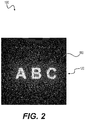
- FIG. 2 shows an exemplary marking 120 of reflective ink lighting assembly 100 in a lit state.
- no external or ambient light is present.
- the lit state is achieved.
- light from the light source is inserted into light transferring medium 110, which illuminates the ink.
- light travelling through light transferring medium 110 via TIR reflects off of the reflective ink, which makes marking 120 (e.g., "A B C") visible.
- marking 120 e.g., "A B C”
- color-matched inks may be used in the markings and coupled with a plurality of colored LEDs to make separate portions of the image set illuminate depending on which LEDs are turned on.
- a beam pattern resulting from illumination provides an intensity, a size, and a shape that meets legal automotive signal lamp photometric requirements.
- Certain embodiments of the present disclosure may be used to improve lighting efficiency of the lighting assemblies. For example, a total amount of usable light may be increased for a given amount of light provided (e.g., from a light source) by printing reflective ink on particular (e.g., non-essential) exit faces. Instead of exiting the lighting assembly via non-beneficial surfaces, light is reflected back into the light transferring media.
- a total amount of usable light may be increased for a given amount of light provided (e.g., from a light source) by printing reflective ink on particular (e.g., non-essential) exit faces. Instead of exiting the lighting assembly via non-beneficial surfaces, light is reflected back into the light transferring media.
- FIG. 3 shows marking 120 when reflective ink lighting assembly 100 is in an unlit state.
- the unlit state is achieved when an internal light source of the lighting assembly is off.
- external or ambient light is present such that marking 120 (e.g., "A B C") is visible.
- marking 120 e.g., "A B C”
- the bright spot overlapping the "B" of the marking is an artifact of the rendering.
- the reflective nature of the ink enables the images of the markings to appear visible when the lighting assembly is in the unlit state.
- Ambient light may enter via transparent or semi-transparent portions of the lighting assembly such as one or more lenses. The ambient light reflects off the reflective ink making it externally visible through the transparent or semi-transparent portion.
- the unlit appearance of the markings may be customized. For example, denser ink applications appear opaque, while lighter ink applications appear milky or translucent.
- the density of ink may be adjusted by varying the thickness of ink layers or by printing a dot matrix, for example.
Abstract
Description
- Embodiments of the present invention relate generally to the field of light assemblies for use in vehicles. More specifically, embodiments of this invention include markings used in combination with a light source within the light assemblies.
-
U.S. Patent 7,804,418 to Sullivan et al. discloses a light assembly for a vehicle that includes a lens having one or more ink markings. At least a portion of the ink marking is configured such that it appears generally opaque to a viewer when unlit, while not appearing opaque when lit by a light source in the light assembly. - European Patent Application
2,746,647 to George et al. discloses a light pipe assembly that enables a uniform emitted light intensity along its length while being lit with a single localized light source. - In an embodiment, a reflective-ink lighting assembly includes a light transferring medium, a reflective-ink marking provided on the light transferring medium, and a light source adapted to insert light into the light transferring medium in a lit state, such that the light propagates through the light transferring medium by total-internal reflection to illuminate the reflective-ink marking. In an unlit state, the reflective-ink marking remains visible in the presence of ambient light.
- In another embodiment, a lighting assembly includes a reflective-ink marking printed on an inner side of a light transferring medium, and a light source adapted to propagate light through the light transferring medium. Propagated light reflects off the reflective-ink marking and exits through a facade of the light transferring medium.
- Illustrative embodiments of the present invention are described in detail below with reference to the attached drawing figures, which are incorporated by reference herein and wherein:
-
FIG. 1 is a perspective view of a reflective ink lighting assembly, in an embodiment; -
FIG. 2 shows an embodiment of an illuminated marking of a reflective ink lighting assembly in a lit state; and -
FIG. 3 shows an embodiment of the marking ofFIG. 2 with the reflective ink lighting assembly in an unlit state. - In certain lighting applications, markings (e.g., logos, designs, emblems, geometric shapes, graphics, text, etc.) may be incorporated into a light assembly for producing a desired visual effect. Incorporating markings into vehicle light assemblies is complicated by photometric requirements of particular vehicle lights. For example, vehicle brake light assemblies must provide a specific total illumination surface area and illumination intensity. Embodiments of the present disclosure incorporate a reflective ink in the markings.
- To provide a desired visual effect, markings may be arranged in an image set. In certain embodiments, the image set is provided on an individual light transferring medium or a plurality of light transferring media layered upon one another to form a stackup of images.
- An exemplary process for transferring an image set onto light transferring media is pad printing.
U.S. Patent 7,804,418 to Sullivan et al. , the disclosure of which is hereby incorporated by reference in its entirety, provides an exemplary pad printing process for applying markings to lighting assemblies. -
FIG. 1 is a perspective view of an exemplary reflectiveink lighting assembly 100.Lighting assembly 100 includes alight transferring medium 110 having a marking 120 (e.g., "A B C") printed with reflective ink on an inner side oflight transferring medium 110. Examples oflight transferring medium 110 include a light guide or light pipe in which light propagates through the medium via total-internal reflection (TIR). The reflective ink is applied to the opposite side of thelighting assembly 100 from the desired direction of light propagation. In other words, the reflective ink is applied to an inner far side oflight transferring medium 110 for light to propagate from a near side oflight transferring medium 110, as depicted inFIG. 1 . Light is introduced intolight transferring medium 110 along an edge (e.g., along a top edge 112) via a light source. The light source may include one or more light-emitting diodes (LEDs). In the embodiment depicted inFIG. 1 , the light source includes an array of LEDs 131-139. - Light from the one or more LEDs propagates through
light transferring medium 110 via TIR. As depicted inFIG. 1 , light emitted from only asingle LED 135 is shown for clarity of illustration. Exemplary rays of internal light are illustrated with dashed lines and exemplary rays of external light are illustrated with solid lines. Note that some rays of light are frustrated out of a façade (e.g., a forward-facing side) oflight transferring medium 110 by reflecting off of reflective ink marking 120. The term "facade" as used herein should be interpreted broadly, in that it is intended to include any portion of the assembly that might be viewed whilelighting assembly 100 is in operation. The resulting beam pattern is formed by the reflective ink. In other words, if no reflective ink were provided, no marking would be illuminated as there would be nothing to direct light out of the façade oflight transferring medium 110. -
FIG. 2 shows an exemplary marking 120 of reflectiveink lighting assembly 100 in a lit state. As depicted inFIG. 2 , no external or ambient light is present. When the light source oflighting assembly 100 is on, the lit state is achieved. In the lit state, light from the light source is inserted intolight transferring medium 110, which illuminates the ink. In other words, light travelling throughlight transferring medium 110 via TIR reflects off of the reflective ink, which makes marking 120 (e.g., "A B C") visible. In certain embodiments, color-matched inks may be used in the markings and coupled with a plurality of colored LEDs to make separate portions of the image set illuminate depending on which LEDs are turned on. - Upon illumination in the lit state, the reflective ink frustrates the TIR light causing it to exit the light transferring media. This causes the image set of the marking to glow substantially homogenously. In certain embodiments, a beam pattern resulting from illumination provides an intensity, a size, and a shape that meets legal automotive signal lamp photometric requirements. By modulating the density of the ink applied, advantageous visual effects are provided, such as shadowing and/or creating a perception of depth.
- Certain embodiments of the present disclosure may be used to improve lighting efficiency of the lighting assemblies. For example, a total amount of usable light may be increased for a given amount of light provided (e.g., from a light source) by printing reflective ink on particular (e.g., non-essential) exit faces. Instead of exiting the lighting assembly via non-beneficial surfaces, light is reflected back into the light transferring media.
-
FIG. 3 shows marking 120 when reflectiveink lighting assembly 100 is in an unlit state. The unlit state is achieved when an internal light source of the lighting assembly is off. As depicted inFIG. 3 , external or ambient light is present such that marking 120 (e.g., "A B C") is visible. Note that the bright spot overlapping the "B" of the marking is an artifact of the rendering. The reflective nature of the ink enables the images of the markings to appear visible when the lighting assembly is in the unlit state. Ambient light may enter via transparent or semi-transparent portions of the lighting assembly such as one or more lenses. The ambient light reflects off the reflective ink making it externally visible through the transparent or semi-transparent portion. - By varying the density of ink applied in the markings, the unlit appearance of the markings may be customized. For example, denser ink applications appear opaque, while lighter ink applications appear milky or translucent. The density of ink may be adjusted by varying the thickness of ink layers or by printing a dot matrix, for example.
- Features described above as well as those claimed below may be combined in various ways without departing from the scope hereof. The following examples illustrate some possible, non-limiting combinations:
- (A1) A reflective-ink lighting assembly includes a light transferring medium, a reflective-ink marking provided on the light transferring medium, and a light source adapted to insert light into the light transferring medium in a lit state, such that the light propagates through the light transferring medium by total-internal reflection to illuminate the reflective-ink marking. In an unlit state, the reflective-ink lighting assembly is configured such that the reflective-ink marking remains visible in the presence of ambient light.
- (A2) For the reflective-ink lighting assembly denoted as (A1), the reflective-ink marking may be applied via pad printing.
- (A3) For the reflective-ink lighting assembly denoted as either (A1) or (A2), the reflective-ink marking may be applied on an inner far side of the light transferring medium opposite a desired direction of light propagation.
- (A4) For the reflective-ink lighting assembly denoted as any of (A1) through (A3), the light source may introduce light into the light transferring medium along an edge of the light transferring medium.
- (A5) For the reflective-ink lighting assembly denoted as any of (A1) through (A4), the light source may include one or more light-emitting diodes.
- (A6) For the reflective-ink lighting assembly denoted as any of (A1) through (A5), the light source may include an array of light-emitting diodes.
- (A7) For the reflective-ink lighting assembly denoted as any of (A1) through (A6), in the lit state, rays of light may be frustrated out of a façade of the light transferring medium by reflecting off of the reflective-ink marking such that the reflective-ink marking is visible in the absence of ambient light.
- (A8) For the reflective-ink lighting assembly denoted as any of (A1) through (A7), ambient light may enter the lighting assembly via transparent or semi-transparent portions of the reflective-ink lighting assembly and reflect off the reflective-ink marking making it externally visible through the facade.
- (A9) For the reflective-ink lighting assembly denoted as any of (A1) through (A8), a beam pattern resulting from illumination in the lit state may provide an intensity, a size, and a shape that meets legal automotive signal lamp photometric requirements.
- (A10) For the reflective-ink lighting assembly denoted as any of (A1) through (A9), reflective ink may be printed on non-essential exit faces of a lighting assembly to increase a total amount of usable light by reflecting light back into the light transferring medium thereby increasing a light efficiency of the lighting assembly.
- (A11) For the reflective-ink lighting assembly denoted as any of (A1) through (A10), the reflective-ink marking may further include an image set provided on the light transferring medium.
- (A12) For the reflective-ink lighting assembly denoted as any of (A1) through (A11), the image set may be provided on a plurality of light transferring media layered upon one another to form a stackup of images.
- (A13) For the reflective-ink lighting assembly denoted as any of (A1) through (A12), the image set may glow substantially homogenously when illuminated in the lit state.
- (A14) For the reflective-ink lighting assembly denoted as any of (A1) through (A13), the light source may include colored light-emitting diodes providing a plurality of colors and the markings may include color-matched inks to enable separate portions of the image set to be illuminated via the colored light-emitting diodes.
- (B1) A lighting assembly includes a reflective-ink marking printed on an inner side of a light transferring medium, and a light source adapted to propagate light through the light transferring medium. Propagated light reflects off the reflective-ink marking and exits through a façade of the light transferring medium.
- (B2) For the lighting assembly denoted as (B1), the inner side on which the reflective-ink marking is printed may be opposite the façade of the light transferring medium.
- (B3) The lighting assembly denoted as either (B1) or (B2) may include a lit state when the light source is on and an unlit state when the light source is off. The reflective-ink marking is illuminated in the lit state via the light source and in the unlit state via ambient light.
- (B4) For the lighting assembly denoted as any of (B1) through (B3), the reflective-ink marking may include an image set printed on one or more layers of the light transferring medium arranged in a stackup such that light reflected off the reflective-ink marking frustrates through the light transferring medium to glow substantially homogenously in the lit state.
- (B5) For the lighting assembly denoted as any of (B1) through (B4), the reflective-ink marking may provide an opaque appearance due to a dense application of ink in the marking.
- (B6) For the lighting assembly denoted as any of (B1) through (B5), the reflective-ink marking may provide a translucent appearance due to a light application of ink in the marking.
- Many different arrangements of the various components depicted, as well as components not shown, are possible without departing from the scope of the present invention. Embodiments of the present invention have been described with the intent to be illustrative rather than restrictive. Alternative embodiments will become apparent to those skilled in the art that do not depart from its scope. A skilled artisan may develop alternative means of implementing the aforementioned improvements without departing from the scope of the present invention.
- It will be understood that certain features and subcombinations are of utility and may be employed without reference to other features and subcombinations and are contemplated within the scope of the claims. Not all operations listed in the various figures need be carried out in the specific order described.
Claims (15)
- A reflective-ink lighting assembly (100), comprising:a light transferring medium (110);a reflective-ink marking (120) provided on the light transferring medium;a light source adapted to insert light into the light transferring medium in a lit state, such that the light propagates through the light transferring medium by total-internal reflection to illuminate the reflective-ink marking; andin an unlit state, the reflective-ink lighting assembly is configured such that the reflective-ink marking remains visible in the presence of ambient light.
- The reflective-ink lighting assembly of claim 1, wherein the reflective-ink marking is applied via pad printing.
- The reflective-ink lighting assembly of claim 1 or claim 2, wherein the reflective-ink marking is applied on an inner far side of the light transferring medium opposite a desired direction of light propagation.
- The reflective-ink lighting assembly of any one of claims 1 to 3, wherein the light source introduces light into the light transferring medium along an edge (112) of the light transferring medium.
- The reflective-ink lighting assembly of any one of claims 1 to 4, wherein the light source includes one or more light-emitting diodes, and/or wherein the light source includes an array of light-emitting diodes (131-139).
- The reflective-ink lighting assembly of any one of claims 1 to 5, wherein, in the lit state, rays of light are frustrated out of a façade of the light transferring medium by reflecting off of the reflective-ink marking such that the reflective-ink marking is visible in the absence of ambient light, and particularly wherein ambient light enters the lighting assembly via transparent or semi-transparent portions of the reflective-ink lighting assembly and reflects off the reflective-ink marking making it externally visible through the facade.
- The reflective-ink lighting assembly of claim any one of claims 1 to 6, wherein a beam pattern resulting from illumination in the lit state provides an intensity, a size, and a shape that meets legal automotive signal lamp photometric requirements.
- The reflective-ink lighting assembly of any of claims 1 to 7, further comprising reflective ink printed on non-essential exit faces of a lighting assembly to increase a total amount of usable light by reflecting light back into the light transferring medium thereby increasing a light efficiency of the lighting assembly.
- The reflective-ink lighting assembly of any one of claims 1 to 8, wherein the reflective-ink marking further comprises an image set provided on the light transferring medium.
- The reflective-ink lighting assembly of claim 9, wherein the image set is provided on a plurality of light transferring media layered upon one another to form a stackup of images, and/or wherein the image set glows substantially homogenously when illuminated in the lit state.
- The reflective-ink lighting assembly of any one of claims 1 to 10, wherein the light source comprises colored light-emitting diodes providing a plurality of colors and the markings include color-matched inks to enable separate portions of the image set to be illuminated via the colored light-emitting diodes.
- A lighting assembly, comprising:a reflective-ink marking printed on an inner side of a light transferring medium; anda light source adapted to propagate light through the light transferring medium, wherein propagated light reflects off the reflective-ink marking and exits through a façade of the light transferring medium.
- The lighting assembly of claim 12, wherein the inner side on which the reflective-ink marking is printed is opposite the façade of the light transferring medium.
- The lighting assembly of claim 12 or 13, further comprising a lit state when the light source is on and an unlit state when the light source is off, the reflective-ink marking being illuminated in the lit state via the light source and in the unlit state via ambient light.
- The lighting assembly of any one of claims 12 to 14, wherein the reflective-ink marking includes an image set printed on one or more layers of the light transferring medium arranged in a stackup such that light reflected off the reflective-ink marking frustrates through the light transferring medium to glow substantially homogenously in the lit state, and/or wherein the reflective-ink marking provides an opaque appearance due to a dense application of ink in the marking and/or wherein the reflective-ink marking provides a translucent appearance due to a light application of ink in the marking.
Applications Claiming Priority (1)
| Application Number | Priority Date | Filing Date | Title |
|---|---|---|---|
| US201862630934P | 2018-02-15 | 2018-02-15 |
Publications (2)
| Publication Number | Publication Date |
|---|---|
| EP3528236A2 true EP3528236A2 (en) | 2019-08-21 |
| EP3528236A3 EP3528236A3 (en) | 2019-11-06 |
Family
ID=65443687
Family Applications (1)
| Application Number | Title | Priority Date | Filing Date |
|---|---|---|---|
| EP19157313.8A Pending EP3528236A3 (en) | 2018-02-15 | 2019-02-14 | Reflective ink lighting assembly |
Country Status (2)
| Country | Link |
|---|---|
| US (1) | US10851952B2 (en) |
| EP (1) | EP3528236A3 (en) |
Families Citing this family (1)
| Publication number | Priority date | Publication date | Assignee | Title |
|---|---|---|---|---|
| USD881278S1 (en) * | 2018-06-13 | 2020-04-14 | Si On Kim | Label |
Citations (2)
| Publication number | Priority date | Publication date | Assignee | Title |
|---|---|---|---|---|
| US7804418B2 (en) | 2006-02-21 | 2010-09-28 | Ventra Greenwich Holdings Corporation | Vehicle light assembly and manufacturing method |
| EP2746647A2 (en) | 2012-12-21 | 2014-06-25 | Flex-N-Gate Advanced Product Development, LLC | Light guide with uniform light intensity |
Family Cites Families (17)
| Publication number | Priority date | Publication date | Assignee | Title |
|---|---|---|---|---|
| US3553869A (en) * | 1968-06-24 | 1971-01-12 | Gilbert & Barker Mfg Co | Illuminated sign |
| RU2165650C2 (en) | 1995-09-08 | 2001-04-20 | Леонардо Инвестментс Лимитед | Illuminated sign and its board |
| US6632506B1 (en) * | 1998-04-23 | 2003-10-14 | Consumer Care Products Inc. | High-visibility traction tape having embedded particle traction surface |
| JP2001163117A (en) * | 1999-12-10 | 2001-06-19 | Toyoda Gosei Co Ltd | Illuminating plate for automobile |
| GB0006327D0 (en) | 2000-03-16 | 2000-05-03 | 3M Innovative Properties Co | Light guides suitable for illuminated displays |
| EP1284870B1 (en) * | 2001-03-27 | 2008-12-10 | Serigraph Inc. | Reflective printed article and method of manufacturing same |
| GB2416063A (en) * | 2004-07-08 | 2006-01-11 | Kristjan Arnthorsson | Layered graphic display panel |
| TW201025101A (en) * | 2008-12-31 | 2010-07-01 | Asustek Comp Inc | Touch pad and electronic device |
| US9028123B2 (en) * | 2010-04-16 | 2015-05-12 | Flex Lighting Ii, Llc | Display illumination device with a film-based lightguide having stacked incident surfaces |
| JP2014021400A (en) | 2012-07-20 | 2014-02-03 | Muto Kogyo Kk | Image display body and preparation device thereof |
| US20150246636A1 (en) * | 2014-02-28 | 2015-09-03 | Nozomu Hope Shigaki | Illuminated plate for motor vehicle |
| US10760762B2 (en) | 2015-05-22 | 2020-09-01 | Flex-N-Gate Advanced Product Development, Llc | Lit image projection lamp and assemblies and methods to use the same to generate three-dimensional images |
| JP2018518033A (en) | 2015-05-22 | 2018-07-05 | フレックス−エヌ−ゲート アドバンスト プロダクト ディベロップメント エルエルシーFlex−N−Gate Advanced Product Development, Llc | Luminescent image projection lamp and method |
| US11402091B2 (en) | 2015-08-31 | 2022-08-02 | Flex-N-Gate Advanced Product Development, Llc | Lamp assembly with thermal transporter |
| ES2938212T3 (en) | 2016-06-13 | 2023-04-05 | Flex N Gate Advanced Product Dev Llc | Illuminated imaging devices and lamp assemblies containing the same for generating three-dimensional images |
| FI20165716A (en) * | 2016-09-23 | 2018-03-24 | Docover Oy | Multilayer structure including a graphic pattern |
| TW201909220A (en) * | 2017-07-21 | 2019-03-01 | 致伸科技股份有限公司 | Luminous keyboard |
-
2019
- 2019-02-11 US US16/272,191 patent/US10851952B2/en active Active
- 2019-02-14 EP EP19157313.8A patent/EP3528236A3/en active Pending
Patent Citations (2)
| Publication number | Priority date | Publication date | Assignee | Title |
|---|---|---|---|---|
| US7804418B2 (en) | 2006-02-21 | 2010-09-28 | Ventra Greenwich Holdings Corporation | Vehicle light assembly and manufacturing method |
| EP2746647A2 (en) | 2012-12-21 | 2014-06-25 | Flex-N-Gate Advanced Product Development, LLC | Light guide with uniform light intensity |
Also Published As
| Publication number | Publication date |
|---|---|
| US20190249834A1 (en) | 2019-08-15 |
| US10851952B2 (en) | 2020-12-01 |
| EP3528236A3 (en) | 2019-11-06 |
Similar Documents
| Publication | Publication Date | Title |
|---|---|---|
| JP5115284B2 (en) | Scuff plate | |
| JP5902387B2 (en) | Vehicle signal transmission device having three-dimensional optical effect | |
| JP5478467B2 (en) | Vehicle exterior garnish | |
| JP2014116142A (en) | Vehicular lighting unit | |
| JP2007227356A (en) | Vehicular lighting fixture | |
| CN102889535A (en) | Lamp assembly | |
| CN112005047A (en) | Signalling device for a motor vehicle | |
| JP2010040322A (en) | Lighting fixture for vehicle | |
| JP2007276726A (en) | Lighting fixture for vehicle | |
| US10851952B2 (en) | Reflective ink lighting assembly | |
| JP4949051B2 (en) | Vehicle lighting device | |
| CN105899405A (en) | Motor vehicle signal light having a pivoting light-diffusing screen, and associated rear body area of a vehicle | |
| JP2014212079A (en) | Light guide plate and lighting fixture having light guide plate | |
| JP2018120708A (en) | Vehicular lighting fixture | |
| JP6879052B2 (en) | Vehicle lighting | |
| JP2007203823A (en) | Lighting system | |
| EP3853068B1 (en) | Vehicle lamp assembly | |
| JP2008020294A (en) | Instrument device for vehicle | |
| CN111164347B (en) | Lighting device for vehicle | |
| US11256018B2 (en) | Light assembly including an illuminating utility segment and a visual stimulant segment | |
| JP7063068B2 (en) | Lighting equipment | |
| JP2017210011A (en) | Vehicle interior material | |
| CN220488978U (en) | Concealed lighting device for motor vehicle signal lamp | |
| JP7383926B2 (en) | Vehicle lights | |
| CN109827144B (en) | Optical system for realizing two uniform luminous effects in same functional area of lamp |
Legal Events
| Date | Code | Title | Description |
|---|---|---|---|
| PUAI | Public reference made under article 153(3) epc to a published international application that has entered the european phase |
Free format text: ORIGINAL CODE: 0009012 |
|
| STAA | Information on the status of an ep patent application or granted ep patent |
Free format text: STATUS: THE APPLICATION HAS BEEN PUBLISHED |
|
| AK | Designated contracting states |
Kind code of ref document: A2 Designated state(s): AL AT BE BG CH CY CZ DE DK EE ES FI FR GB GR HR HU IE IS IT LI LT LU LV MC MK MT NL NO PL PT RO RS SE SI SK SM TR |
|
| AX | Request for extension of the european patent |
Extension state: BA ME |
|
| PUAL | Search report despatched |
Free format text: ORIGINAL CODE: 0009013 |
|
| AK | Designated contracting states |
Kind code of ref document: A3 Designated state(s): AL AT BE BG CH CY CZ DE DK EE ES FI FR GB GR HR HU IE IS IT LI LT LU LV MC MK MT NL NO PL PT RO RS SE SI SK SM TR |
|
| AX | Request for extension of the european patent |
Extension state: BA ME |
|
| RIC1 | Information provided on ipc code assigned before grant |
Ipc: G09F 13/18 20060101AFI20190930BHEP Ipc: B60Q 1/30 20060101ALI20190930BHEP Ipc: G09F 13/22 20060101ALI20190930BHEP |
|
| STAA | Information on the status of an ep patent application or granted ep patent |
Free format text: STATUS: REQUEST FOR EXAMINATION WAS MADE |
|
| 17P | Request for examination filed |
Effective date: 20200506 |
|
| RBV | Designated contracting states (corrected) |
Designated state(s): AL AT BE BG CH CY CZ DE DK EE ES FI FR GB GR HR HU IE IS IT LI LT LU LV MC MK MT NL NO PL PT RO RS SE SI SK SM TR |
|
| STAA | Information on the status of an ep patent application or granted ep patent |
Free format text: STATUS: EXAMINATION IS IN PROGRESS |
|
| 17Q | First examination report despatched |
Effective date: 20210520 |
|
| RAP3 | Party data changed (applicant data changed or rights of an application transferred) |
Owner name: FLEX-N-GATE ADVANCED PRODUCT DEVELOPMENT, LLC |