EP3527977A1 - Ultraschallprüfvorrichtung und verfahren zur herstellung eines ultraschallprüfkopfs für eine derartige ultraschallprüfvorrichtung - Google Patents
Ultraschallprüfvorrichtung und verfahren zur herstellung eines ultraschallprüfkopfs für eine derartige ultraschallprüfvorrichtung Download PDFInfo
- Publication number
- EP3527977A1 EP3527977A1 EP19153763.8A EP19153763A EP3527977A1 EP 3527977 A1 EP3527977 A1 EP 3527977A1 EP 19153763 A EP19153763 A EP 19153763A EP 3527977 A1 EP3527977 A1 EP 3527977A1
- Authority
- EP
- European Patent Office
- Prior art keywords
- ultrasonic
- side surfaces
- testing device
- coupling surface
- housing
- Prior art date
- Legal status (The legal status is an assumption and is not a legal conclusion. Google has not performed a legal analysis and makes no representation as to the accuracy of the status listed.)
- Granted
Links
Images



Classifications
-
- G—PHYSICS
- G01—MEASURING; TESTING
- G01N—INVESTIGATING OR ANALYSING MATERIALS BY DETERMINING THEIR CHEMICAL OR PHYSICAL PROPERTIES
- G01N29/00—Investigating or analysing materials by the use of ultrasonic, sonic or infrasonic waves; Visualisation of the interior of objects by transmitting ultrasonic or sonic waves through the object
- G01N29/22—Details, e.g. general constructional or apparatus details
- G01N29/225—Supports, positioning or alignment in moving situation
- G01N29/226—Handheld or portable devices
-
- B—PERFORMING OPERATIONS; TRANSPORTING
- B06—GENERATING OR TRANSMITTING MECHANICAL VIBRATIONS IN GENERAL
- B06B—METHODS OR APPARATUS FOR GENERATING OR TRANSMITTING MECHANICAL VIBRATIONS OF INFRASONIC, SONIC, OR ULTRASONIC FREQUENCY, e.g. FOR PERFORMING MECHANICAL WORK IN GENERAL
- B06B1/00—Methods or apparatus for generating mechanical vibrations of infrasonic, sonic, or ultrasonic frequency
- B06B1/02—Methods or apparatus for generating mechanical vibrations of infrasonic, sonic, or ultrasonic frequency making use of electrical energy
- B06B1/06—Methods or apparatus for generating mechanical vibrations of infrasonic, sonic, or ultrasonic frequency making use of electrical energy operating with piezoelectric effect or with electrostriction
- B06B1/0607—Methods or apparatus for generating mechanical vibrations of infrasonic, sonic, or ultrasonic frequency making use of electrical energy operating with piezoelectric effect or with electrostriction using multiple elements
- B06B1/0622—Methods or apparatus for generating mechanical vibrations of infrasonic, sonic, or ultrasonic frequency making use of electrical energy operating with piezoelectric effect or with electrostriction using multiple elements on one surface
-
- G—PHYSICS
- G01—MEASURING; TESTING
- G01M—TESTING STATIC OR DYNAMIC BALANCE OF MACHINES OR STRUCTURES; TESTING OF STRUCTURES OR APPARATUS, NOT OTHERWISE PROVIDED FOR
- G01M13/00—Testing of machine parts
- G01M13/04—Bearings
- G01M13/045—Acoustic or vibration analysis
-
- G—PHYSICS
- G01—MEASURING; TESTING
- G01N—INVESTIGATING OR ANALYSING MATERIALS BY DETERMINING THEIR CHEMICAL OR PHYSICAL PROPERTIES
- G01N29/00—Investigating or analysing materials by the use of ultrasonic, sonic or infrasonic waves; Visualisation of the interior of objects by transmitting ultrasonic or sonic waves through the object
- G01N29/04—Analysing solids
- G01N29/043—Analysing solids in the interior, e.g. by shear waves
-
- G—PHYSICS
- G01—MEASURING; TESTING
- G01N—INVESTIGATING OR ANALYSING MATERIALS BY DETERMINING THEIR CHEMICAL OR PHYSICAL PROPERTIES
- G01N29/00—Investigating or analysing materials by the use of ultrasonic, sonic or infrasonic waves; Visualisation of the interior of objects by transmitting ultrasonic or sonic waves through the object
- G01N29/22—Details, e.g. general constructional or apparatus details
-
- G—PHYSICS
- G01—MEASURING; TESTING
- G01N—INVESTIGATING OR ANALYSING MATERIALS BY DETERMINING THEIR CHEMICAL OR PHYSICAL PROPERTIES
- G01N29/00—Investigating or analysing materials by the use of ultrasonic, sonic or infrasonic waves; Visualisation of the interior of objects by transmitting ultrasonic or sonic waves through the object
- G01N29/22—Details, e.g. general constructional or apparatus details
- G01N29/26—Arrangements for orientation or scanning by relative movement of the head and the sensor
- G01N29/262—Arrangements for orientation or scanning by relative movement of the head and the sensor by electronic orientation or focusing, e.g. with phased arrays
-
- G—PHYSICS
- G01—MEASURING; TESTING
- G01N—INVESTIGATING OR ANALYSING MATERIALS BY DETERMINING THEIR CHEMICAL OR PHYSICAL PROPERTIES
- G01N29/00—Investigating or analysing materials by the use of ultrasonic, sonic or infrasonic waves; Visualisation of the interior of objects by transmitting ultrasonic or sonic waves through the object
- G01N29/22—Details, e.g. general constructional or apparatus details
- G01N29/28—Details, e.g. general constructional or apparatus details providing acoustic coupling, e.g. water
-
- G—PHYSICS
- G01—MEASURING; TESTING
- G01N—INVESTIGATING OR ANALYSING MATERIALS BY DETERMINING THEIR CHEMICAL OR PHYSICAL PROPERTIES
- G01N2291/00—Indexing codes associated with group G01N29/00
- G01N2291/10—Number of transducers
- G01N2291/106—Number of transducers one or more transducer arrays
-
- G—PHYSICS
- G01—MEASURING; TESTING
- G01N—INVESTIGATING OR ANALYSING MATERIALS BY DETERMINING THEIR CHEMICAL OR PHYSICAL PROPERTIES
- G01N2291/00—Indexing codes associated with group G01N29/00
- G01N2291/26—Scanned objects
- G01N2291/269—Various geometry objects
- G01N2291/2696—Wheels, Gears, Bearings
Definitions
- the invention relates to an ultrasonic testing device with an ultrasonic probe for testing an internal component of a large rolling bearing and also to a method for producing an ultrasonic probe for such ultrasonic testing device.
- Ultrasonic testing devices are well known in the art in a variety of applications.
- a device with a test head is known, which is inserted laterally into the large rolling bearing for testing an inner component of a large rolling bearing.
- Such slewing bearings can be provided in particular to store rotating assemblies of a wind turbine, such as rotors or machine nacelles.
- the shows US 2010/0275692 A1 a phased array ultrasonic testing apparatus having a plurality of ultrasonic transducers arranged in two rows. This device is used, for example, to measure the thickness of materials.
- an ultrasonic testing apparatus uses a thin layer of liquid to couple the ultrasonic waves into a test object.
- test head Since the test head is introduced only temporarily into the large rolling bearing for testing, it is possible to dispense with components permanently installed in the slewing bearing for non-destructive workpiece testing, for example on ultrasonic sensors or eddy current sensors.
- components permanently installed in the slewing bearing for non-destructive workpiece testing, for example on ultrasonic sensors or eddy current sensors.
- the installation space available for insertion or insertion of the test head into the slewing bearing is typically very limited.
- the performance of the test, in particular the ultrasonic testing, on the inner component of the rolling bearing, such as on a rolling element or a running surface thus requires an advanced miniaturization of the test head to be introduced.
- the object of the present invention is to provide an ultrasonic testing device with a compact ultrasonic probe, which is designed to be inserted laterally in a large roller bearing so that it can be applied to an internal component of the large rolling bearing for testing.
- this object is achieved by a method having the features of claim 12.
- An ultrasonic testing device with an ultrasonic probe for testing an inner component of a slewing bearing has a rigid housing designed for insertion into a slewing bearing.
- the housing comprises a coupling surface, a coupling surface opposite the lid surface and perpendicular to the coupling surface and the lid surface extending, first and second side surfaces.
- the first and second side surfaces each have the same, the height of the housing defining vertical extent.
- Attached to the coupling surface are a plurality of ultrasonic transducers for coupling ultrasonic waves into the component to be tested, which are arranged in at least one linear row which runs parallel to the lateral extent of the first side surfaces.
- Each ultrasonic transducer is contacted via extending within a housing of the ultrasonic probe contact wires, in the Substantially in a plane parallel to the coupling surface and are connected to cables which are coupled to one of the second side surfaces.
- the "lateral extent of a side surface” is understood according to the invention to mean the longitudinal direction of the side surface when it is approximated by a rectangular area.
- the first and second side surfaces are preferably arranged transversely to one another.
- ultrasonic probes for non-destructive workpiece testing are designed such that the cables for driving the ultrasonic transducers are connected to an opposite side of the ultrasonic head of the coupling surface. This requires a relatively large height. It has been found that this type of ultrasonic probes is not suitable for being inserted laterally in slewing bearings, as this usually only a lateral access or gap is available, which is in the range of about one centimeter. Such a narrow access may in particular be formed between a cage and a rotor main bearing.
- ultrasonic probes with conventional cable routing can generally not be used to check the inner components of a large-diameter rolling bearing in the final assembled state, provided they are not permanently integrated in the slewing bearing, ie are installed.
- the ultrasonic probe is adapted in its objective embodiment of the special application of ultrasonic testing, in which the ultrasonic probe is used only temporarily for testing in the large rolling bearing.
- the ultrasonic probe has for this purpose a very low height. In order to provide a low height or to minimize the vertical extent of the ultrasonic probe, the contact of the ultrasonic transducer and the cable guide has been adjusted.
- the individual ultrasonic transducers are preferably contacted within the housing by contact wires in such a way that the contact wires run at least in sections parallel to the lateral extent of the first side faces.
- the contact wires preferably have a second, shorter section which is arranged parallel to the lateral extent of the second side surfaces is. In this way, a laterally or laterally extending through the housing signal line is provided.
- the contact wires are respectively connected to cables which are connected or coupled to one of the second side surfaces.
- the contact wires thus extend mainly in the direction of the length and width of the housing (and only slightly in height).
- the contact wires therefore extend in a plane parallel to the coupling surface of the housing or in a plane parallel to the cover.
- the space in the vertical direction, ie in the direction of the vertical extent of the ultrasonic probe or its housing is therefore minimal, so that the ultrasonic probe can be inserted through very narrow accesses or gaps in an interior of the large rolling bearing.
- the housing is rigid, d. H. not flexible.
- the contact wires may in particular be arranged substantially L-shaped within the housing.
- the lateral extent of the first side surfaces of the housing are preferably greater than the lateral extent of the second side surfaces.
- the ultrasonic test head thus has a substantially parallelepiped-shaped form, wherein the ultrasonic transducers are arranged in a row or in a plurality of rows, which run parallel to the lateral extent of the first side surfaces, which have the greater lateral extent.
- the ultrasonic transducers thus run substantially parallel to the length of the cuboid.
- the housing of the ultrasonic probe has a vertical extension of less than 1 cm, in particular less than 8 mm, for example about 7.2 mm.
- the housing is preferably formed at least in part from a material which does not bend or only marginally deflect when a mechanical load occurs as a result of the ultrasonic test.
- the housing is at least partially made of a metal or a metal alloy.
- the side surfaces made of a metal or a metal alloy.
- the metal or metal alloy preferably comprises iron, carbon, chromium, molybdenum and / or aluminum.
- the cables can be designed as coaxial cable, in particular as multi-core multi-coaxial cable.
- the ultrasonic probe of the ultrasonic testing device is formed in a preferred embodiment as a phased array probe.
- Such designs are known per se in the prior art and generally include controllable ultrasonic transducers, in which the propagation direction of the emitted ultrasonic waves or cones can be changed and / or pivoted.
- test area can thus be flexibly changed so that different areas can be examined without having to change the position of the ultrasound head.
- Such designs are preferred in the context of the present application area, since the space available for positioning the ultrasonic probe within the large rolling bearing, in particular within a Wälz stressesraums to be tested, is limited.
- an electronic control and / or evaluation unit designed for this purpose may be provided.
- the ultrasonic probe is designed as a linear phased array probe with only a linear, so rectilinear, series of ultrasonic transducers.
- the ultrasonic probe in one embodiment, it is provided to form the ultrasonic probe as a matrix-shaped phased array probe.
- the ultrasonic transducers are arranged in this embodiment in at least two mutually parallel rows.
- a three-dimensional pivoting of the propagation direction of the emitted ultrasonic waves or cones is possible, so that a particularly large examination area can be covered.
- the ultrasonic transducers arranged in different rows are preferably acoustically insulated from one another by insulation elements. Such insulation elements reduce noise between the ultrasonic transducers, in particular, the so-called "cross-talk" can be minimized to improve the validity of the measurement results.
- Suitable insulation elements consist for example of cork, rubber materials or another material which has a low permeability to ultrasound.
- the insulation elements may also be formed of composite materials comprising cork and rubber materials (also: rubber cork). These materials are available by the meter and are preferably used in thicknesses of 0.8 mm to 2.0 mm.
- the ultrasonic transducers are encapsulated within the housing by means of an acoustically damping and hardened suspension (ie potting compound), in particular by means of a suspension containing tungsten oxide (WO 3 ).
- an acoustically damping and hardened suspension ie potting compound
- a suspension containing tungsten oxide WO 3
- the suspension is preferably electrically insulating.
- contact wires in stripped state ie without insulating plastic sheath, are introduced into the housing to further minimize the space required for contacting the ultrasonic transducer space.
- the suspension also ensures mechanical protection of the contact wires or the contacting points with the ultrasonic transducers.
- tungsten oxide-containing suspension is preferred, since this additionally contributes to the damping of the mechanical vibrations of the ultrasonic transducer.
- the hardened suspension seals the ultrasonic probe outwards against the influence of media.
- the surface of the coupling-in surface and / or the cover surface preferably consists, at least in sections, of a hardened suspension, in particular of a suspension containing tungsten oxide.
- a plurality of cables arranged parallel to one another are coupled to one of the second side surfaces and connected to the contact wires. In this way, a large number of ultrasonic transducers can be contacted, while minimizing the height or while minimizing the vertical extent of the ultrasonic probe perpendicular to the coupling surface.
- ultrasonic transducers are provided in two rows.
- the intended for contacting contact wires are connected to four cables, each of which is designed as a 16-core multi-coaxial cable and are coupled in parallel side by side on one of the second side surfaces.
- the cross-section of the cable can correspond in this objective embodiment, at least approximately the vertical extent of the housing.
- each contact wire for contacting the ultrasonic transducers is connected to a separate core of the multicore cables.
- At least one tube for supplying a coupling fluid to the coupling surface of the ultrasonic probe can be coupled to one of the second side surfaces.
- the coupling fluid or medium preferably has a low viscosity and may be provided by an oil.
- the at least one tube for supplying the coupling fluid or medium may be in fluid communication with outlet openings on the coupling surface of the ultrasonic probe.
- the coupling fluid or medium used in the ultrasonic test to facilitate the coupling of the ultrasonic waves in the component to be tested or in the component to be tested.
- a magnetic fixing device for temporarily fixing the ultrasound head to the component to be tested is attached to the coupling surface.
- the magnetic fixing device comprises, for example, a plurality of permanent magnets distributed over the coupling surface and frictionally fixing the ultrasonic test head via its coupling surface against the component to be tested.
- the ultrasonic probe can be attached to the end of a guide rail.
- a further magnetic fixing device for fixing the guide rail is provided on the large roller bearing.
- the further fixing device comprises, for example, further permanent magnets and is designed to frictionally fix the ultrasonic testing device on the outside, for example, to a cage of the slewing bearing.
- the guide rail has at least two rail sections running at an obtuse angle relative to one another.
- the concrete geometric dimensions of the guide rail and the angle at which the at least two rail sections are arranged relative to one another are adapted to the shape of the large rolling bearing to be tested.
- the geometric dimensions are adapted so that the ultrasound test head fastened to the guide rail at the end can be arranged at a suitable position within the slewing bearing when the fixing device is fixed.
- the at least one row of ultrasonic transducers can be fixed by introducing and curing a layer of a suspension, in particular a suspension containing tungsten oxide, the layer forming the coupling surface.
- the ultrasonic transducers can be contacted with contact wires without insulating plastic sheath.
- the layer or layers of the suspension in the liquid state and by a thermal treatment at 35 ° C to 45 ° C for 3.5 hours to 4.5 hours, especially at about 40 ° C for about 4 hours, cure.
- the first layer insulation elements for acoustic insulation can be additionally fixed in position.
- elongate isolation elements are disposed between parallel rows of ultrasonic transducers to attenuate spurious signals.
- the introduced insulation elements are fixed in position.
- the ultrasonic testing device described above can be produced by the described method.
- FIG. 1 and FIG. 2 show an ultrasonic probe 1 for an ultrasonic testing apparatus 100 for testing inner components of a large rolling bearing.
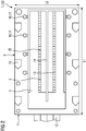
- the ultrasonic probe 1 has a substantially cuboidal housing 3, with a coupling surface 5, one of the coupling surface 5 opposite and parallel to the lid surface 7, and perpendicular to the coupling surface 5 extending first and second side surfaces 9, 11th
- the first side surfaces 9 have, as in particular from the top view of FIG. 2 can be seen, a lateral extent L1, which is greater than the lateral extent L2 of the second side surfaces 11th
- the second side surfaces 11 are arranged substantially transversely to the first side surfaces 9. Accordingly, the projections of the first and second side surfaces 9, 11 in plan view of FIG FIG. 2 a right angle to each other.
- multicore cables 12 are connected to one of the second side surfaces 11 and serve to transmit control signals and response signals which actuate piezoelectric ultrasonic transducers 13 or are generated by them as a function of a detected ultrasound echo.
- the ultrasonic transducers 13 are arranged in the illustrated, not limiting embodiment in two parallel rows.
- an elongated insulating element 14 made of cork, which serves to minimize the so-called "cross-talk" between the ultrasonic transducers 13 of different rows.
- a central region ZD of the cover surface 7 and a central region ZE of the coupling surface 5 are formed by a hardened suspension containing tungsten oxide (WO 3 ).
- the vertical extent V of the first and second side surfaces 9, 11 essentially determines the overall height of the housing 3 of the ultrasonic probe 1.
- the height is designed so that the ultrasonic probe 1 can be inserted into a gap or otherwise shaped access laterally in a slewing bearing.
- outlet openings 19 are further provided for a coupling fluid, which are fluidly connected with hoses 21.
- the hoses 21 are used to supply the coupling fluid to the ultrasonic probe 1 (see FIG. 3 ).
- the ultrasonic test head 1 is arranged at the end on an angled guide rail 23 which has two rail sections 25, 27.
- the rail sections 25, 27 extend at an obtuse angle to each other. This angle is in the illustrated embodiment in about 120 °.
- the guide rail 23 is used for insertion of the ultrasonic probe 1 in the interior of the large rolling bearing and for frictional fixing desselbigen.
- a further fixing device 29 is provided on the ultrasonic probe 1 opposite end of the guide rail 23, which comprises further permanent magnets.
- the further fixing device 29 serves for frictional fixing of the guide rail 23 and the ultrasonic test head 1 attached thereto during the ultrasonic testing.
- the manufacturing method of the ultrasonic probe 1 has been adjusted.
- the housing 3 is provided, more precisely the mutually transverse first and second side surfaces 9, 11, and the regions of the coupling surface 5 or the cover surface 7 surrounding the central region ZD or ZE.
- a linear array of ultrasonic transducers 13 is provided which is disposed within the housing 3 such that the linear array of ultrasonic transducers 13 is parallel to the lateral extent L1 of the first side surfaces 9.
- a suspension containing tungsten oxide (WO 3 ) is then applied at a height of, for example, approximately 1.5 mm in the housing 3 defined by the first and second side surfaces 9, 11 and cured by thermal treatment. This serves for the electrical insulation and the mechanical protection of the components.
- the ultrasonic transducers 13 are fixed, and it is the coupling surface 5 is formed.
- Each contact wire 31 has a portion 33 which runs parallel to the lateral extent L1 of the first side surfaces 9 of the ultrasonic probe 1, and a further, shorter portion 35 for contacting the respective ultrasonic transducer 13.
- the shorter portion 35 is parallel to the lateral extent L2 of the second side surfaces 11.
- the contact wires 31 in a plane which is substantially parallel to the coupling surface 5, guided past the piezoelectric ultrasonic transducers 13 within the housing, in particular between the first side surfaces 9 and the linear array ultrasonic transducer 13, and with the at one of second side surfaces 11 coupled cables 12 connected.
- a corresponding number of contact wires 31 or coaxial lines is required for electrification of the piezoelectric ultrasonic transducers 13, for example of an ultrasonic test head 1 equipped with 64 ultrasonic transducers 13, ie 64 contact wires 31 or coaxial lines.
- 64 contact wires 31 or coaxial lines due to the dimensional limitations, not a single 64-core cable 12, but a plurality of, for example, four 16-core cables 12, particularly multi-coaxial cables, are connected to respective contact wires 31 disposed in the plane of the piezoelectric ultrasonic transducers 13 and laterally out of the housing 3 led out. This is in detail in FIG. 4 shown.
- a tungsten oxide-containing suspension is now again in the in FIG. 4 apparent rectangular cavity filled until the top of the housing 3 is reached.
- the suspension fulfills two essential tasks: On the one hand, it serves to dampen the mechanical vibrations of the piezoelectric ultrasonic transducers 13 and thus ensures a broadband pulse spectrum. On the other hand, the hardened suspension closes the housing 3 or the ultrasonic test head 1 to the outside against the influence of media and thus likewise forms part of the cover surface 7.
- the suspension to be applied in the liquid state is preferably cured for 4 hours in an oven at about 40 ° C.
Landscapes
- Physics & Mathematics (AREA)
- General Physics & Mathematics (AREA)
- Immunology (AREA)
- Pathology (AREA)
- Analytical Chemistry (AREA)
- Biochemistry (AREA)
- General Health & Medical Sciences (AREA)
- Life Sciences & Earth Sciences (AREA)
- Health & Medical Sciences (AREA)
- Chemical & Material Sciences (AREA)
- Acoustics & Sound (AREA)
- Engineering & Computer Science (AREA)
- Mechanical Engineering (AREA)
- Investigating Or Analyzing Materials By The Use Of Ultrasonic Waves (AREA)
- Particle Formation And Scattering Control In Inkjet Printers (AREA)
- Transducers For Ultrasonic Waves (AREA)
Abstract
Description
- Die Erfindung betrifft eine Ultraschallprüfvorrichtung mit einem Ultraschallprüfkopf zum Prüfen einer inneren Komponente eines Großwälzlagers und ferner ein Verfahren zur Herstellung eines Ultraschallprüfkopfs für eine derartige Ultraschallprüfvorrichtung.
- Vorrichtungen zur Ultraschallprüfung sind aus dem Stand der Technik in unterschiedlichen Anwendungsgebieten hinlänglich bekannt.
- So ist beispielsweise aus der
WO 2014/202752 A1 eine Vorrichtung mit einem Prüfkopf bekannt, der zum Prüfen einer inneren Komponente eines Großwälzlagers seitlich in das Großwälzlager eingeführt wird. Derartige Großwälzlager können insbesondere dazu vorgesehen sein, rotierende Baugruppen einer Windkraftanlage zu lagern, beispielsweise Rotoren oder Maschinengondeln. - Außerdem zeigt die
US 2010/0275692 A1 eine Phased-Array Ultraschallprüfvorrichtung mit einer Vielzahl von Ultraschallwandlern, die in zwei Reihen angeordnet sind. Diese Vorrichtung wird beispielsweise verwendet, um die Dicke von Materialien zu messen. - In der
DE 10 2011 076 224 A1 ist eine mehrteilige Befestigungsvorrichtung für einen Ultraschallwandler offenbart, wobei ein Teil der Befestigungsvorrichtung aus einer ausgehärteten Vergussmasse gebildet wird. - Aus der
US 2007/0175282 A1 ist eine Ultraschallprüfvorrichtung bekannt, die zum Einkoppeln der Ultraschallwellen in ein Testobjekt eine dünne Flüssigkeitsschicht verwendet. - Weiterhin ist in der
DE 31 49 933 A1 eine magnetische Befestigungsvorrichtung für eine Ultraschallprüfvorrichtung gezeigt. - Da der Prüfkopf zur Prüfung lediglich temporär in das Großwälzlager eingeführt wird, kann auf permanent in dem Großwälzlager verbaute Komponenten zur zerstörungsfreien Werkstückprüfung verzichtet werden, beispielsweise auf Ultraschallsensoren oder Wirbelstromsensoren. Allerdings ist der zum Einführen bzw. Einsetzen des Prüfkopfs in das Großwälzlager zur Verfügung stehende Bauraum typischerweise sehr begrenzt. Die Durchführung der Prüfung, insbesondere der Ultraschallprüfung, an der inneren Komponente des Wälzlagers, wie etwa an einem Wälzkörper oder einer Lauffläche, erfordert somit eine fortgeschrittene Miniaturisierung des einzuführenden Prüfkopfs.
- Die Aufgabe der vorliegenden Erfindung besteht darin, eine Ultraschallprüfvorrichtung mit einem kompakten Ultraschallprüfkopf anzugeben, der dazu ausgelegt ist, seitlich in ein Großwälzlager derart eingeführt zu werden, sodass dieser zum Prüfen an eine innere Komponente des Großwälzlagers angelegt werden kann.
- Hinsichtlich der Vorrichtung wird diese Aufgabe durch eine Ultraschallprüfvorrichtung gemäß Anspruch 1 gelöst.
- Hinsichtlich des Herstellungsverfahrens wird diese Aufgabe durch ein Verfahren mit den Merkmalen des Anspruchs 12 gelöst.
- Vorteilhafte Ausgestaltungen der Erfindung sind Gegenstand der abhängigen Ansprüche.
- Eine Ultraschallprüfvorrichtung mit einem Ultraschallprüfkopf zum Prüfen einer inneren Komponente eines Großwälzlagers weist ein zum Einführen in ein Großwälzlager ausgebildetes starres Gehäuse auf. Das Gehäuse umfasst eine Einkoppelfläche, eine der Einkoppelfläche gegenüberliegende Deckelfläche und senkrecht zur Einkoppelfläche und zur Deckelfläche verlaufende, erste und zweite Seitenflächen. Die ersten und zweiten Seitenflächen haben jeweils die gleiche, die Bauhöhe des Gehäuses bestimmende vertikale Ausdehnung. An der Einkoppelfläche sind eine Vielzahl von Ultraschallwandlern zum Einkoppeln von Ultraschallwellen in die zu prüfende Komponente angebracht, die in zumindest einer linearen Reihe angeordnet sind, die parallel zur lateralen Ausdehnung der ersten Seitenflächen verläuft. Jeder Ultraschallwandler ist über innerhalb eines Gehäuses des Ultraschallprüfkopfs verlaufende Kontaktdrähte kontaktiert, die im Wesentlichen in einer Ebene parallel zur Einkoppelfläche verlaufen und mit Kabeln verbunden sind, die an einer der zweiten Seitenflächen angekoppelt sind.
- Unter der "lateralen Ausdehnung einer Seitenfläche" wird erfindungsgemäß die Längsrichtung der Seitenfläche verstanden, wenn diese durch eine rechteckige Fläche approximiert wird.
- Die ersten und zweiten Seitenflächen sind vorzugsweise quer zueinander angeordnet.
- Typischerweise sind Ultraschallprüfköpfe zur zerstörungsfreien Werkstückprüfung derart ausgelegt, dass die Kabel zum Ansteuern der Ultraschallwandler auf einer der Einkoppelfläche gegenüberliegenden Seite des Ultraschallkopfs angeschlossen sind. Dies bedingt eine relative große Bauhöhe. Es hat sich herausgestellt, dass diese Art von Ultraschallprüfköpfen nicht dazu geeignet ist, in Großwälzlager seitlich eingeführt zu werden, da hierfür meist nur ein seitlicher Zugang bzw. Spalt zu Verfügung steht, der im Bereich von etwa einem Zentimeter liegt. Ein derartiger schmaler Zugang kann insbesondere zwischen einem Käfig und einem Rotorhauptlager gebildet sein.
- Ultraschallprüfköpfe mit herkömmlicher Kabelführung können aufgrund ihrer Bauhöhe im Allgemeinen nicht dazu verwendet werden, um innere Komponenten eines Großwälzlagers im endmontierten Zustand zu prüfen, sofern diese nicht in das Großwälzlager permanent integriert, also eingebaut sind.
- Der Ultraschallprüfkopf ist in seiner gegenständlichen Ausgestaltung an den speziellen Anwendungsfall der Ultraschallprüfung angepasst, bei der der Ultraschallprüfkopf lediglich temporär zur Prüfung in das Großwälzlager eingesetzt wird. Der Ultraschallprüfkopf weist hierzu eine sehr geringe Bauhöhe auf. Um eine geringe Bauhöhe bereitzustellen bzw. die vertikale Ausdehnung des Ultraschallprüfkopfs zu minimieren, wurde die Kontaktierung der Ultraschallwandler und die Kabelführung angepasst.
- Die einzelnen Ultraschallwandler sind innerhalb des Gehäuses von Kontaktdrähten bevorzugt derart kontaktiert, dass die Kontaktdrähte zumindest abschnittsweise parallel zur lateralen Ausdehnung der ersten Seitenflächen verlaufen. Bevorzugt weisen die Kontaktdrähte einen zweiten, kürzeren Abschnitt auf, der parallel zur lateralen Ausdehnung der zweiten Seitenflächen angeordnet ist. Auf diese Weise wird eine seitlich bzw. lateral durch das Gehäuse verlaufende Signalleitung bereitgestellt. Die Kontaktdrähte sind entsprechend mit Kabeln verbunden, die an einer der zweiten Seitenflächen angeschlossen bzw. angekoppelt sind.
- Die Kontaktdrähte verlaufen also vor allem in Richtung der Länge und der Breite des Gehäuses (und nur unwesentlich in der Höhe). Die Kontaktdrähte verlaufen daher in einer Ebene parallel zur Einkoppelfäche des Gehäuses bzw. in einer Ebene parallel zum Deckel.
- Der Bauraum in vertikaler Richtung, also in Richtung der vertikalen Ausdehnung des Ultraschallprüfkopfs bzw. dessen Gehäuses ist daher minimal, so dass der Ultraschallprüfkopf durch sehr schmale Zugänge bzw. Spalte in einen Innenraum des Großwälzlagers eingeführt werden kann. Damit der Ultraschallprüfkopf gezielt an die zu prüfende Komponente des Großwälzlagers, beispielsweise an eine Lauffläche oder an einen Wälzkörper, angelegt werden kann, ist das Gehäuse starr, d. h. nicht flexibel ausgebildet.
- Die Kontaktdrähte können insbesondere im Wesentlichen L-förmig innerhalb des Gehäuses angeordnet sein.
- Die laterale Ausdehnung der ersten Seitenflächen des Gehäuses sind bevorzugt größer als die laterale Ausdehnung der zweiten Seitenflächen. Der Ultraschallprüfkopf hat somit eine im Wesentlichen quaderförmig ausgeprägte Form, wobei die Ultraschallwandler in einer Reihe oder in mehreren Reihen angeordnet sind, die parallel zur lateralen Ausdehnung der ersten Seitenflächen verlaufen, welche die größere laterale Ausdehnung aufweisen.
- Die Ultraschallwandler verlaufen also im Wesentlichen parallel zur Länge des Quaders.
- In einer bevorzugten Ausführungsform weist das Gehäuse des Ultraschallprüfkopfs eine vertikale Ausdehnung von weniger als 1 cm auf, insbesondere von weniger als 8 mm, beispielsweise etwa 7,2 mm.
- Das Gehäuse ist vorzugsweise zumindest zum Teil aus einem Material gebildet, welches sich bei einer durch die Ultraschallprüfung auftretende mechanischen Belastung nicht oder nur unwesentlich durchbiegt.
- Vorzugsweise besteht das Gehäuse zumindest zum Teil aus einem Metall oder einer Metalllegierung. Bevorzugt bestehen die Seitenflächen aus einem Metall oder einer Metalllegierung. Das Metall oder die Metalllegierung umfasst bevorzugt Eisen, Kohlenstoff, Chrom, Molybdän und/oder Aluminium.
- Die Kabel können als Koaxialkabel ausgeführt sein, insbesondere als mehradrige Multi-Koaxialkabel.
- Der Ultraschallprüfkopf der Ultraschallprüfvorrichtung ist in einer bevorzugten Ausführungsform als Phased-Array-Prüfkopf ausgebildet.
- Derartige Ausbildungen sind im Stand der Technik an sich bekannt und umfassen im Allgemeinen ansteuerbare Ultraschallwandler, bei denen die Propagationsrichtung der emittierten Ultraschallwellen bzw. -kegel verändert und/oder geschwenkt werden kann.
- Über eine geeignete elektronische Ansteuerung ist damit der Prüfbereich flexibel veränderbar, so dass verschiedene Bereiche untersucht werden können, ohne die Position des Ultraschallkopfs verändern zu müssen. Derartige Ausbildungen sind im Zusammenhang des hier vorliegenden Anwendungsgebiets bevorzugt, da der zur Positionierung des Ultraschallprüfkopfs vorhandene Raum innerhalb des Großwälzlagers, insbesondere innerhalb eines zu prüfenden Wälzkörperraums, begrenzt ist.
- Zur geeigneten Ansteuerung der einzelnen Ultraschallwandler kann eine dazu ausgebildete elektronische Steuer- und/oder Auswerteeinheit vorgesehen sein.
- In einer möglichen Ausführung ist der Ultraschallprüfkopf als linearer Phased-Array-Prüfkopf mit nur einer linearen, also geradlinigen, Reihe von Ultraschallwandlern ausgebildet.
- In einer Weiterbildung der Erfindung ist vorgesehen, den Ultraschallprüfkopf als matrixförmigen Phased-Array-Prüfkopf auszubilden. Die Ultraschallwandler sind in dieser Ausführungsform in zumindest zwei parallel zueinander verlaufenden Reihen angeordnet. Durch eine entsprechende Ansteuerung der Ultraschallwandler ist dann ein dreidimensionales Verschwenken der Propagationsrichtung der emittierten Ultraschallwellen bzw. -kegel möglich, so dass ein besonders großer Untersuchungsbereich abgedeckt werden kann.
- Bevorzugt sind die in unterschiedlichen Reihen angeordneten Ultraschallwandler durch Isolationselemente akustisch voneinander isoliert. Derartige Isolationselemente vermindern Störsignale zwischen den Ultraschallwandlern, insbesondere kann der so genannte "Cross-Talk" minimiert werden, um die Aussagekraft der Messergebnisse zu verbessern.
- Geeignete Isolationselemente bestehen beispielsweise aus Kork, Kautschukmaterialien oder einem anderen Material, welches ein geringes Durchdringungsvermögen für Ultraschall aufweist.
- Die Isolationselemente können auch aus Verbundmaterialien gebildet sein, die Kork und Kautschukmaterialien (auch: Gummikork) umfassen. Diese Materialien sind als Meterware erhältlich und werden bevorzugt in Stärken von 0,8 mm bis 2,0 mm verwendet.
- In einer Ausführungsform sind die Ultraschallwandler innerhalb des Gehäuses mittels einer akustisch dämpfenden und ausgehärteten Suspension (d.h. Vergussmasse) vergossen, insbesondere mittels einer Wolframoxid (WO3) enthaltenden Suspension.
- Die Suspension ist vorzugsweise elektrisch isolierend. In diesem Fall können Kontaktdrähte im abisolierten Zustand, also ohne isolierende Kunststoffummantelung, in das Gehäuse eingebracht werden, um den zur Kontaktierung der Ultraschallwandler notwendigen Bauraum weiter zu minimieren. Die elektrische Isolierung der Kontaktdrähte erfolgt über die Suspension, in der die Kontaktdrähte eingebettet sind.
- Die Suspension stellt darüber hinaus einen mechanischen Schutz der Kontaktdrähte bzw. der Kontaktierungsstellen mit den Ultraschallwandlern sicher.
- Als Suspension ist eine Wolframoxid enthaltende Suspension bevorzugt, da diese zusätzlich zur Dämpfung der mechanischen Schwingungen der Ultraschallwandler beiträgt.
- Die Verwendung einer Wolframoxid enthaltenden Suspension stellt somit ein breitbandiges Pulsspektrum sicher, welches einem Ultraschallimpuls von kurzer Dauer entspricht.
- Des Weiteren verschließt die ausgehärtete Suspension den Ultraschallprüfkopf nach außen gegen den Einfluss von Medien.
- Bevorzugt besteht die Oberfläche der Einkoppelfläche und/oder der Deckelfläche zumindest abschnittsweis aus einer ausgehärteten Suspension, insbesondere aus einer Wolframoxid enthaltenden Suspension.
- Des Weiteren kann vorgesehen sein, dass mehrere parallel zueinander angeordnete Kabel an einer der zweiten Seitenflächen angekoppelt und mit den Kontaktdrähten verbunden sind. Auf diese Weise können eine große Anzahl von Ultraschallwandlern kontaktiert werden, bei gleichzeitiger Minimierung der Bauhöhe bzw. bei gleichzeitiger Minimierung der vertikalen Ausdehnung des Ultraschallprüfkopfs senkrecht zur Einkoppelfläche.
- Bei Ultraschallprüfköpfen, welche eine große Anzahl von Ultraschallwandlern aufweisen, hat es sich als vorteilhaft erwiesen, mehrere mehradrige Kabel vorzusehen, da ein einziges mehradriges Kabel aufgrund des relativ großen Querschnitts bereits einen vergleichsweise großen Bauraum in vertikaler Richtung in Anspruch nehmen würde.
- In einer vorteilhaften Ausgestaltung der Erfindung sind beispielsweise 64 Ultraschallwandler in zwei Reihen vorgesehen. Die zur Kontaktierung vorgesehenen Kontaktdrähte sind mit vier Kabeln verbunden, die jeweils als 16-adrige Multi-Koaxialkabel ausgeführt sind und parallel nebeneinander an einer der zweiten Seitenflächen angekoppelt sind. Der Querschnitt der Kabel kann bei dieser gegenständlichen Ausbildung zumindest näherungsweise der vertikalen Ausdehnung des Gehäuses entsprechen.
- Vorzugsweise ist jeder Kontaktdraht zum Kontaktieren der Ultraschallwandler mit einer separaten Ader der mehradrigen Kabel verbunden.
- An einer der zweiten Seitenflächen kann zumindest ein Schlauch zum Zuführen eines Koppelfluids zur Einkoppelfläche des Ultraschallprüfkopfs angekoppelt sein. Das Koppelfluid oder-medium weist vorzugsweise eine niedrige Viskosität auf und kann von einem Öl bereitgestellt sein.
- Der zumindest eine Schlauch zum Zuführen des Koppelfluids oder -medium kann in fluidischer Verbindung mit Austrittsöffnungen an der Einkoppelfläche des Ultraschallprüfkopfs stehen.
- Das Koppelfluid oder -medium dient bei der Ultraschallprüfung dazu, das Einkoppeln der Ultraschallwellen in das zu prüfende Bauteil bzw. in die zu prüfende Komponente zu erleichtern.
- In einer Ausführungsform ist an der Einkoppelfläche eine magnetische Fixereinrichtung zum temporären Fixieren des Ultraschallkopfs an der zu prüfenden Komponente angebracht. Die magnetische Fixiereinrichtung umfasst beispielsweise mehrere, über die Einkoppelfläche verteilt angeordnete Permanentmagnete, die den Ultraschallprüfkopf über seine Einkoppelfläche an der zu prüfenden Komponente kraftschlüssig fixieren.
- Der Ultraschallprüfkopf kann endseitig an einer Führungsschiene befestigt sein. An dem dem Ultraschallprüfkopf abgewandten bzw. gegenüberliegenden Ende der Führungsschiene ist eine weitere magnetische Fixiereinrichtung zum Fixieren der Führungsschiene an dem Großwälzlager vorgesehen. Die weitere Fixiereinrichtung umfasst beispielsweise weitere Permanentmagnete und ist dazu ausgebildet, die Ultraschallprüfvorrichtung außenseitig beispielsweise an einem Käfig des Großwälzlager kraftschlüssig zu fixieren.
- In einer Ausgestaltung der Erfindung weist die Führungsschiene zumindest zwei, zueinander in einem stumpfen Winkel verlaufende Schienenabschnitte auf. Die konkreten geometrischen Abmessungen der Führungsschiene sowie der Winkel, in dem die zumindest zwei Schienenabschnitte zueinander angeordnet sind, sind auf die Gestalt des zu prüfenden Großwälzlager angepasst. Insbesondere sind die geometrischen Abmessungen so angepasst, dass der endseitig an Führungsschiene befestigte Ultraschallprüfkopf bei fixierter weiterer Fixiereinrichtung an einer geeigneten Stelle innerhalb des Großwälzlagers angeordnet werden kann.
- Ein Verfahren zum Herstellen eines Ultraschallprüfkopfs für eine Ultraschallprüfvorrichtung umfasst die folgende Schritte:
- a) Bereitstellen zumindest einer linearen Reihe Ultraschallwandler und eines Gehäuses des Ultraschallprüfkops, das erste und zweite Seitenflächen hat, wobei die ersten und zweiten Seitenflächen quer zueinander verlaufen,
- b) Anordnen der zumindest einen linearen Reihe Ultraschallwandler parallel zur lateralen Ausdehnung der ersten Seitenflächen in dem Gehäuse,
- c) Fixieren der zumindest einen linearen Reihe Ultraschallwandler durch Vergießen, wobei eine Einkoppelfläche des Ultraschallprüfkopfs gebildet wird, und
- d) Kontaktieren der Ultraschallwandler mit Kontaktdrähten, welche im Wesentlichen in einer Ebene parallel zur Einkoppelfläche verlaufen und zu einer der zweiten Seitenflächen geführt werden, an welcher die Kontaktdrähte mit Kabeln verbunden werden.
- Die zumindest eine Reihe Ultraschallwandler kann durch Einbringen und Aushärten einer Lage einer Suspension, insbesondere einer Wolframoxid enthaltenen Suspension, fixiert werden, wobei die Lage die Einkoppelfläche bildet.
- Außerdem kann vorgesehen sein, dass das Verfahren ferner den folgenden Schritt umfasst:
- e) Bilden der Deckelfläche durch eine Lage der Suspension, insbesondere der Wolframoxid enthaltenden Suspension, die eingebracht und ausgehärtet wird, wobei die Kontaktdrähte mechanisch fixiert werden.
- Die Ultraschallwandler können mit Kontaktdrähten ohne isolierende Kunststoffummantelung kontaktiert werden.
- Vorteile des Herstellungsverfahrens ergeben sich unmittelbar bereits aus der vorhergehenden Beschreibung mit Bezug auf die Ultraschallvorrichtung bzw. des Ultraschallprüfkopfs.
- Insbesondere wird durch das angegebene Herstellungsverfahren eine geringe Bauhöhe bezüglich der vertikalen Ausdehnung des Ultraschallprüfkopfs sichergestellt, da eine seitliche Kabelführung bereitgestellt wird. Wenn die Kontaktdrähte ohne isolierende Kunststoffummantelung eingebracht werden, können sehr kompakte Bauformen realisiert werden. Die notwendige elektrische Isolierung wird in diesem Fall von der ausgehärteten Suspension bereitgestellt.
- In einer Ausgestaltung des erfindungsgemäßen Verfahrens ist vorgesehen, die Lage bzw. die Lagen der Suspension in flüssigem Zustand einzubringen und durch eine thermische Behandlung bei 35° C bis 45° C für 3,5 Stunden bis 4,5 Stunden, insbesondere bei etwa 40° C für etwa 4 Stunden, auszuhärten.
- Durch Einbringen und Aushärten der ersten Lage können zusätzlich Isolationselemente zur akustischen Isolation in ihrer Position fixiert werden.
- Beispielsweise werden längliche Isolationselemente zwischen parallelen Reihen von Ultraschallwandlern angeordnet, um Störsignale zu dämpfen. Durch Einbringen und Aushärten der Suspension werden die eingebrachten Isolationselemente in ihrer Position fixiert.
- Vor allem kann die zuvor beschriebene Ultraschallprüfvorrichtung mit dem beschriebenen Verfahren hergestellt sein.
- Die Erfindung wird nachstehend auch hinsichtlich weiterer Merkmale und Vorteile anhand der Beschreibung von Ausführungsbeispielen und unter Bezugnahme auf die beiliegende Zeichnung näher erläutert. Dabei zeigen:
-
Figur 1 einen Ultraschallprüfkopf für eine Ultraschallprüfvorrichtung in einer perspektivischen Darstellung, -
Figur 2 eine Draufsicht auf eine Einkoppelseite des Ultraschallprüfkopfs derFigur 1 , -
Figur 3 eine perspektivische Darstellung des Ultraschallprüfkopfs derFigur 1 endseitig an einer Führungsschiene befestigt und mit angeschlossenen Schläuchen zur Zuführung von Koppelfluid, und -
Figur 4 eine Unteransicht des Ultraschallprüfkopfs derFigur 1 während der Herstellung, wobei die Kontaktierung von angeordneten Ultraschallwandlern durch Kontaktdrähte sichtbar ist. - Gleiche oder funktionsgleiche Teile sind in allen Figuren mit denselben Bezugszeichen versehen.
-
Figur 1 undFigur 2 zeigen einen Ultraschallprüfkopf 1 für eine Ultraschallprüfvorrichtung 100 zum Prüfen von inneren Komponenten eines Großwälzlagers. - Der Ultraschallprüfkopf 1 weist ein im Wesentlichen quaderförmiges Gehäuse 3 auf, mit einer Einkoppelfläche 5, einer der Einkoppelfläche 5 gegenüberliegende und dazu parallel verlaufende Deckelfläche 7, und senkrecht zur Einkoppelfläche 5 verlaufenden ersten und zweiten Seitenflächen 9, 11.
- Die ersten Seitenflächen 9 weisen, wie insbesondere aus der Draufsicht der
Figur 2 ersichtlich, eine laterale Ausdehnung L1 auf, die größer ist als die laterale Ausdehnung L2 der zweiten Seitenflächen 11. - Die zweiten Seitenflächen 11 sind im Wesentlichen quer zu den ersten Seitenflächen 9 angeordnet. Dementsprechend haben die Projektionen der ersten und zweiten Seitenflächen 9, 11 in der Draufsicht der
Figur 2 einen rechten Winkel zueinander. - An einer der zweiten Seitenflächen 11 sind vier parallel zueinander angeordnete, mehradrige Kabel 12 angeschlossen, die zur Übertragung von Steuersignalen und Antwortsignalen dienen, welche piezoelektrische Ultraschallwandler 13 ansteuern bzw. von diesen in Abhängigkeit eines erfassten Ultraschallechos generiert werden.
- Die Ultraschallwandler 13 sind in dem dargestellten, nicht einschränkend aufzufassenden Ausführungsbeispiel in zwei zueinander parallelen Reihen angeordnet.
- Zwischen den beiden parallelen Reihen der Ultraschallwandler 13 befindet sich ein längliches Isolationselement 14 aus Kork, welches dazu dient, den so genannten "Cross-Talk" zwischen den Ultraschallwandlern 13 unterschiedlicher Reihen zu minimieren.
- Ein zentraler Bereich ZD der Deckelfläche 7 und ein zentraler Bereich ZE der Einkoppelfläche 5 sind durch eine ausgehärtete Suspension gebildet, die Wolframoxid (WO3) enthält.
- Randseitig um den zentralen Bereich ZE der Einkoppelfläche 5 herum sind mehrere Permanentmagnete 15 angeordnet, die als magnetische Fixiereinrichtung 17 zum kraftschlüssigen Fixieren des Ultraschallprüfkopfs 1 über seine Einkoppelfläche 5 an einer zu prüfenden Komponente, insbesondere eines Großwälzlagers, fungieren.
- Die vertikale Ausdehnung V der ersten und zweiten Seitenflächen 9, 11 bestimmt im Wesentlichen die Bauhöhe des Gehäuses 3 des Ultraschallprüfkopfs 1. Die Bauhöhe ist derart ausgelegt, dass der Ultraschallprüfkopf 1 in einen Spalt oder einen anderweitig geformten Zugang seitlich in ein Großwälzlager eingeführt werden kann.
- An der Einkoppelfläche 5 sind ferner Austrittsöffnungen 19 für ein Kopplungsfluid vorgesehen, die fluidisch mit Schläuchen 21 in Verbindung stehen. Die Schläuche 21 dienen der Zuführung des Kopplungsfluids zum Ultraschallprüfkopf 1 (siehe
Figur 3 ). - Ferner ist zu sehen, dass der Ultraschallprüfkopf 1 endseitig an einer abgewinkelten Führungsschiene 23 angeordnet ist, die zwei Schienenabschnitte 25, 27 aufweist. Die Schienenabschnitte 25, 27 verlaufen in einem stumpfen Winkel zueinander. Dieser Winkel ist in der dargestellten Ausführungsform in etwa 120°.
- Die Führungsschiene 23 dient zum Einführen des Ultraschallprüfkopf 1 in das Innere des Großwälzlagers und zum kraftschlüssigen Fixieren desselbigen. Hierzu ist an dem dem Ultraschallprüfkopf 1 gegenüberliegenden Ende der Führungsschiene 23 eine weitere Fixiereinrichtung 29 vorgesehen, welche weitere Permanentmagnete umfasst. Die weitere Fixiereinrichtung 29 dient zum kraftschlüssigen Fixieren der Führungsschiene 23 und den daran befestigten Ultraschallprüfkopf 1 während der Ultraschallprüfung.
- Um eine kompakte Bauweise des Ultraschallprüfkopfs 1 zu erreichen, wurde das Herstellungsverfahren des Ultraschallprüfkopfs 1 angepasst.
- In einem ersten Verfahrensschritt wird das Gehäuse 3 bereitgestellt, genauer gesagt die zueinander querstehenden ersten und zweiten Seitenflächen 9,11, sowie die den zentralen Bereich ZD bzw. ZE umgebenden Bereiche der Einkoppelfläche 5 bzw. der Deckelfläche 7.
- Zusätzlich wird eine lineare Reihe Ultraschallwandler 13 bereitgestellt, die innerhalb des Gehäuses 3 so angeordnet wird, dass die lineare Reihe Ultraschallwandler 13 parallel zu lateralen Ausdehnung L1 der ersten Seitenflächen 9 ist.
- Zur Herstellung des Ultraschallprüfkopfs 1 wird anschließend eine Wolframoxid (WO3) enthaltende Suspension in einer Höhe von beispielsweise etwa ca. 1,5 mm in das durch die ersten und zweiten Seitenflächen 9, 11 definierte Gehäuse 3 appliziert und durch thermische Behandlung ausgehärtet. Dies dient der elektrischen Isolation und dem mechanischen Schutz der Bauteile. Zusätzlich werden in diesem Schritt auch die Ultraschallwandler 13 fixiert, und es wird die Einkoppelfläche 5 gebildet.
- Anschließend werden die Kontaktdrähte 31, beispielsweise wie in
Figur 4 dargestellt, in das Gehäuse 3 eingebracht. Die abisolierten Kontaktdrähte 31, d.h. die Kontaktdrähte 31 ohne isolierende Kunststoffummantelung, kontaktieren die piezoelektrischen Ultraschallwandlern 13. - Jeder Kontaktdraht 31 weist einen Abschnitt 33 auf, der parallel zur lateralen Ausdehnung L1 der ersten Seitenflächen 9 des Ultraschallprüfkopfes 1 verläuft, sowie einen weiteren, kürzeren Abschnitt 35 zur Kontaktierung des jeweiligen Ultraschallwandlers 13 auf. Der kürzere Abschnitt 35 verläuft parallel zur lateralen Ausdehnung L2 der zweiten Seitenflächen 11.
- In einem nächsten Verfahrensschritt werden die Kontaktdrähte 31 in einer Ebene, die im Wesentlichen parallel zur Einkoppelfläche 5 ist, an den piezoelektrischen Ultraschallwandlern 13 innerhalb des Gehäuses vorbeigeführt, insbesondere zwischen den ersten Seitenflächen 9 und der linearen Reihe Ultraschallwandler 13, und mit den an einer der zweiten Seitenflächen 11 angekoppelten Kabeln 12 verbunden.
- Prinzipiell werden zur Elektrifizierung der piezoelektrischen Ultraschallwandler 13 beispielsweise eines mit 64 Ultraschallwandlern 13 ausgestatteten Ultraschallprüfkopfs 1 eine entsprechende Anzahl an Kontaktdrähte 31 bzw. Koaxialleitungen benötigt, also 64 Kontaktdrähte 31 bzw. Koaxialleitungen. Aufgrund der dimensionalen Beschränkungen wird jedoch kein einzelnes 64-adriges Kabel 12, sondern mehrere, beispielsweise vier 16-adrige Kabel 12, insbesondere multi-Koaxialkabel, mit entsprechenden Kontaktdrähten 31 verbunden, die in der Ebene der piezoelektrischen Ultraschallwandler 13 angeordnet und seitlich aus dem Gehäuse 3 herausgeführt werden. Dies ist im Detail in
Figur 4 dargestellt. - In einem abschließenden Schritt wird nun nochmals eine Wolframoxid enthaltende Suspension in den in
Figur 4 ersichtlichen rechteckigen Hohlraum gefüllt, bis die Oberkante des Gehäuses 3 erreicht wird. - Die Suspension erfüllt hierbei zwei wesentliche Aufgaben: Zum einen dient sie der Dämpfung der mechanischen Schwingungen der piezoelektrischen Ultraschallwandler 13 und sorgt so für ein breitbandiges Pulsspektrum. Zum anderen verschließt die ausgehärtete Suspension das Gehäuse 3 bzw. den Ultraschallprüfkopf 1 nach außen gegen den Einfluss von Medien und bildet somit gleichermaßen einen Teil der Deckelfläche 7.
- Die im flüssigen Zustand zu applizierende Suspension wird vorzugsweise für 4 Stunden in einem Ofen bei etwa 40°C ausgehärtet.
-
- 1
- Ultraschallprüfkopf
- 3
- Gehäuse
- 5
- Einkoppelfläche
- 7
- Deckelfläche
- 9
- erste Seitenfläche
- 11
- zweite Seitenfläche
- 12
- Kabel
- 13
- Ultraschallwandler
- 14
- Isolationselement
- 15
- Permanentmagnet
- 17
- Fixiereinrichtung
- 19
- Austrittsöffnung
- 21
- Schlauch
- 23
- Führungsschiene
- 25
- Schienenabschnitt
- 27
- Schienenabschnitt
- 29
- Fixiereinrichtung
- 31
- Kontaktdraht
- 33
- Abschnitt
- 35
- Abschnitt
- L1
- laterale Ausdehnung
- L2
- laterale Ausdehnung
- V
- vertikale Ausdehnung
- ZD
- zentraler Bereich
- ZE
- zentraler Bereich
- 100
- Ultraschallprüfvorrichtung
Claims (15)
- Ultraschallprüfvorrichtung (100), mit einem Ultraschallprüfkopf (1) zum Prüfen einer inneren Komponente eines Großwälzlagers, welcher ein zum Einführen in ein Großwälzlager ausgebildetes starres Gehäuse (3) aufweist, das eine Einkoppelfläche (5), eine der Einkoppelfläche (5) gegenüberliegenden Deckelfläche (7) und senkrecht zur Einkoppelfläche (5) und zur Deckelfläche (7) verlaufende erste und zweite Seitenflächen (9, 11) umfasst,
wobei die ersten und zweiten Seitenflächen (9, 11) die gleiche, die Bauhöhe des Gehäuses (3) bestimmende vertikale Ausdehnung (V) haben und an der Einkoppelfläche (5) eine Vielzahl von Ultraschallwandlern (13) zum Einkoppeln von Ultraschallwellen in die zu prüfende Komponente angebracht sind, die in zumindest einer linearen Reihe angeordnet sind und im Wesentlichen parallel zur lateralen Ausdehnung (L1) der ersten Seitenflächen (9) verlaufen,
wobei jeder Ultraschallwandler (13) über innerhalb des Gehäuses (3) verlaufende Kontaktdrähte (31) kontaktiert ist, die im Wesentlichen in einer Ebene parallel zur Einkoppelfläche (5) verlaufen und mit Kabeln (12) verbunden sind. - Ultraschallprüfvorrichtung (100) nach Anspruch 1, dadurch gekennzeichnet, dass der Ultraschallprüfkopf (1) als matrixförmiger Phased-Array-Prüfkopf ausgebildet ist, wobei die Ultraschallwandler (13) in zumindest zwei parallel zueinander verlaufenden Reihen angeordnet sind.
- Ultraschallprüfvorrichtung (100) nach Anspruch 1 oder 2, dadurch gekennzeichnet, dass jeder Kontaktdraht (31) einen Abschnitt (33) aufweist, der parallel zur lateralen Ausdehnung (L1) der ersten Seitenflächen (9) verläuft, und insbesondere einen zweiten, kürzeren Abschnitt (35) aufweist, der parallel zur lateralen Ausdehnung (L2) der zweiten Seitenflächen (11) verläuft.
- Ultraschallprüfvorrichtung (100) nach einem der vorhergehenden Ansprüche, dadurch gekennzeichnet, dass die Ultraschallwandler (13) innerhalb des Gehäuses (3) mittels einer dämpfenden und ausgehärteten Suspension, insbesondere einer Wolframoxid enthaltende Suspension, vergossen sind.
- Ultraschallprüfvorrichtung (100) nach Anspruch 4, dadurch gekennzeichnet, dass die Einkoppelfläche (5) durch eine Lage der dämpfenden und ausgehärteten Suspension gebildet ist.
- Ultraschallprüfvorrichtung (100) nach einem der vorhergehenden Ansprüche, dadurch gekennzeichnet, dass mehrere parallel zueinander angeordnete Kabel (12) an einer der zweiten Seitenflächen (11) angekoppelt sind und mit den Kontaktdrähten (31) verbunden sind.
- Ultraschallprüfvorrichtung (100) nach einem der vorhergehenden Ansprüche, dadurch gekennzeichnet, dass an einer der zweiten Seitenflächen (11) zumindest ein Schlauch (21) zum Zuführen ein Koppelfluids oder -mediums zur Einkoppelfläche (5) des Ultraschallprüfkopfs (1) angekoppelt ist.
- Ultraschallprüfvorrichtung (100) nach einem der vorhergehenden Ansprüche, dadurch gekennzeichnet, dass an der Einkoppelfläche (5) eine magnetische Fixiereinrichtung (17) zum temporären Fixieren des Ultraschallprüfkopf (1) an der zu prüfenden Komponente angebracht ist.
- Ultraschallprüfvorrichtung (100) nach einem der vorhergehenden Ansprüche, dadurch gekennzeichnet, dass der Ultraschallprüfkopf (1) endseitig an einer Führungsschiene (23) befestigt ist, welche an dem dem Ultraschallprüfkopf (1) abgewandten Ende eine weitere magnetische Fixiereinrichtung (29) zum Fixieren an dem Großwälzlager aufweist.
- Ultraschallprüfvorrichtung (100) nach Anspruch 9, dadurch gekennzeichnet, dass die Führungsschiene (23) zumindest zwei, zueinander in einem stumpfen Winkel verlaufende Schienenabschnitte (25, 27) aufweist.
- Ultraschallprüfvorrichtung (100) nach einem der vorhergehenden Ansprüche, dadurch gekennzeichnet, dass die laterale Ausdehnung (L1) der ersten Seitenflächen (9) größer ist als die laterale Ausdehnung (L2) der zweiten Seitenflächen (11).
- Verfahren zum Herstellen eines Ultraschallprüfkopfs (1) für eine Ultraschallprüfvorrichtung (100) gemäß einem der vorhergehenden Ansprüche, welches die folgenden Schritte umfasst:a) Bereitstellen zumindest einer linearen Reihe Ultraschallwandler (13) und eines Gehäuses (3) des Ultraschallprüfkopfs (1), das erste und zweite Seitenflächen (9, 11) hat, wobei die ersten und zweiten Seitenflächen (9, 11) quer zueinander verlaufen,b) Anordnen der zumindest einen linearen Reihe Ultraschallwandler (13) parallel zur lateralen Ausdehnung (L1) der ersten Seitenflächen (9) in dem Gehäuse (3),c) Fixieren der zumindest einen linearen Reihe Ultraschallwandler (13) durch Vergießen, wobei eine Einkoppelfläche (5) des Ultraschallprüfkopfs (1) gebildet wird, undd) Kontaktieren der Ultraschallwandler (13) mit Kontaktdrähten (31), welche im Wesentlichen in einer Ebene parallel zur Einkoppelfläche (5) verlaufen und zu einer der zweiten Seitenflächen (11) geführt werden, an welcher die Kontaktdrähte (31) mit Kabeln (12) verbunden werden.
- Verfahren nach Anspruch 12, dadurch gekennzeichnet, dass die zumindest eine Reihe Ultraschallwandler (13) durch Einbringen und Aushärten einer Lage einer Suspension fixiert wird, wobei die Lage die Einkoppelfläche (5) bildet.
- Verfahren nach Anspruch 12 oder 13, dadurch gekennzeichnet, dass das Verfahren ferner den folgenden Schritt umfasst:e) Bilden der Deckelfläche (7) durch eine Lage der Suspension, insbesondere der Wolframoxid enthaltenden Suspension, die eingebracht und ausgehärtet wird, wobei die Kontaktdrähte (31) mechanisch fixiert werden.
- Verfahren nach einem der Ansprüche 13 oder 14, dadurch gekennzeichnet, dass die Lage bzw. die Lagen der Suspension, insbesondere der Wolframoxid enthaltenden Suspension, in flüssigem Zustand eingebracht wird bzw. werden und durch eine thermische Behandlung bei 35 °C bis 45 °C für 3,5 Stunden bis 4,5 Stunden, insbesondere bei etwa 40 °C für etwa 4 Stunden, ausgehärtet wird bzw. werden.
Applications Claiming Priority (1)
| Application Number | Priority Date | Filing Date | Title |
|---|---|---|---|
| DE102018103258.7A DE102018103258B4 (de) | 2018-02-14 | 2018-02-14 | Ultraschallprüfvorrichtung und Verfahren zur Herstellung eines Ultraschallprüfkopfs für eine derartige Ultraschallprüfvorrichtung |
Publications (2)
| Publication Number | Publication Date |
|---|---|
| EP3527977A1 true EP3527977A1 (de) | 2019-08-21 |
| EP3527977B1 EP3527977B1 (de) | 2022-12-14 |
Family
ID=65236892
Family Applications (1)
| Application Number | Title | Priority Date | Filing Date |
|---|---|---|---|
| EP19153763.8A Active EP3527977B1 (de) | 2018-02-14 | 2019-01-25 | Ultraschallprüfvorrichtung und verfahren zur herstellung eines ultraschallprüfkopfs für eine derartige ultraschallprüfvorrichtung |
Country Status (6)
| Country | Link |
|---|---|
| EP (1) | EP3527977B1 (de) |
| DE (1) | DE102018103258B4 (de) |
| DK (1) | DK3527977T3 (de) |
| ES (1) | ES2939955T3 (de) |
| FI (1) | FI3527977T3 (de) |
| PT (1) | PT3527977T (de) |
Families Citing this family (2)
| Publication number | Priority date | Publication date | Assignee | Title |
|---|---|---|---|---|
| CN111730419B (zh) * | 2020-07-07 | 2024-11-08 | 洛阳博智自动控制技术有限公司 | 基于调幅理论的高低频复合超声微雕刻装置及方法 |
| JP7561569B2 (ja) * | 2020-10-22 | 2024-10-04 | 富士フイルム株式会社 | 超音波探触子 |
Citations (8)
| Publication number | Priority date | Publication date | Assignee | Title |
|---|---|---|---|---|
| DE3149933A1 (de) * | 1980-12-16 | 1982-07-15 | Micro Pure Systems, Inc., Smithfield, R.I. | Schallimpuls-echogeraet |
| DE10018355A1 (de) * | 2000-04-13 | 2001-12-20 | Siemens Ag | Ultraschallwandler und Verfahren zur Herstellung eines Ultraschallwandlers |
| US20070175282A1 (en) * | 2006-02-02 | 2007-08-02 | The Boeing Company | Thin-film ultrasonic probe having a flexible membrane |
| US20100275692A1 (en) * | 2009-05-01 | 2010-11-04 | Paul Meyer | Apparatus and system for measuring material thickness |
| US20110025172A1 (en) * | 2009-07-29 | 2011-02-03 | Harhen Edward P | Ultrasound Imaging Transducer Acoustic Stack with Integral Electrical Connections |
| DE102011076224A1 (de) * | 2011-05-20 | 2012-11-22 | Ge Sensing & Inspection Technologies Gmbh | Mehrteilige Befestigungsvorrichtung für einen Ultraschallwandler |
| US20160126445A1 (en) * | 2014-10-31 | 2016-05-05 | Seiko Epson Corporation | Ultrasonic probe as well as electronic apparatus and ultrasonic imaging apparatus |
| US20170055948A1 (en) * | 2015-08-27 | 2017-03-02 | Tyco Electronics Corporation | Probe assembly and system including a modular device and a cable assembly |
Family Cites Families (5)
| Publication number | Priority date | Publication date | Assignee | Title |
|---|---|---|---|---|
| JPS57157154A (en) * | 1981-03-25 | 1982-09-28 | Toshiba Corp | Manufacture of array type ultrasonic probe |
| EP0452516B1 (de) * | 1990-03-16 | 1995-09-27 | Siemens Aktiengesellschaft | Ultraschall-Prüfkopf und Verfahren zu seinem Betrieb |
| JP3379073B2 (ja) * | 1994-06-17 | 2003-02-17 | 本田技研工業株式会社 | 超音波送受波器 |
| CA2229926C (en) * | 1995-08-31 | 2002-02-26 | Alcan International Limited | Ultrasonic probes for use in harsh environments |
| DE102013106470A1 (de) | 2013-06-20 | 2014-12-24 | Intelligendt Systems & Services Gmbh | Vorrichtung und Verfahren zum zerstörungsfreien Prüfen einer Komponente eines Wälzlagers |
-
2018
- 2018-02-14 DE DE102018103258.7A patent/DE102018103258B4/de active Active
-
2019
- 2019-01-25 EP EP19153763.8A patent/EP3527977B1/de active Active
- 2019-01-25 DK DK19153763.8T patent/DK3527977T3/da active
- 2019-01-25 ES ES19153763T patent/ES2939955T3/es active Active
- 2019-01-25 FI FIEP19153763.8T patent/FI3527977T3/fi active
- 2019-01-25 PT PT191537638T patent/PT3527977T/pt unknown
Patent Citations (8)
| Publication number | Priority date | Publication date | Assignee | Title |
|---|---|---|---|---|
| DE3149933A1 (de) * | 1980-12-16 | 1982-07-15 | Micro Pure Systems, Inc., Smithfield, R.I. | Schallimpuls-echogeraet |
| DE10018355A1 (de) * | 2000-04-13 | 2001-12-20 | Siemens Ag | Ultraschallwandler und Verfahren zur Herstellung eines Ultraschallwandlers |
| US20070175282A1 (en) * | 2006-02-02 | 2007-08-02 | The Boeing Company | Thin-film ultrasonic probe having a flexible membrane |
| US20100275692A1 (en) * | 2009-05-01 | 2010-11-04 | Paul Meyer | Apparatus and system for measuring material thickness |
| US20110025172A1 (en) * | 2009-07-29 | 2011-02-03 | Harhen Edward P | Ultrasound Imaging Transducer Acoustic Stack with Integral Electrical Connections |
| DE102011076224A1 (de) * | 2011-05-20 | 2012-11-22 | Ge Sensing & Inspection Technologies Gmbh | Mehrteilige Befestigungsvorrichtung für einen Ultraschallwandler |
| US20160126445A1 (en) * | 2014-10-31 | 2016-05-05 | Seiko Epson Corporation | Ultrasonic probe as well as electronic apparatus and ultrasonic imaging apparatus |
| US20170055948A1 (en) * | 2015-08-27 | 2017-03-02 | Tyco Electronics Corporation | Probe assembly and system including a modular device and a cable assembly |
Also Published As
| Publication number | Publication date |
|---|---|
| DE102018103258B4 (de) | 2020-01-23 |
| DE102018103258A1 (de) | 2019-08-14 |
| ES2939955T3 (es) | 2023-04-28 |
| DK3527977T3 (da) | 2023-03-13 |
| PT3527977T (pt) | 2023-03-10 |
| FI3527977T3 (fi) | 2023-03-23 |
| EP3527977B1 (de) | 2022-12-14 |
Similar Documents
| Publication | Publication Date | Title |
|---|---|---|
| EP3167255B1 (de) | Ultraschallwandleranordnung sowie ultraschallwasserzähler | |
| DE102008004660B4 (de) | Gradientenspule und Verfahren zur Herstellung einer Gradientenspule | |
| DE19925468A1 (de) | Streufeldsonde | |
| DE102019124454A1 (de) | Fluidmesseinrichtung mit einem Fluidgehäuse und Verfahren zur Herstellung eines Fluidgehäuses | |
| DE4124103C1 (de) | ||
| WO2012031988A1 (de) | Vorrichtung zum innenprüfen eines eine hohlzylindrische bohrung aufweisenden werkstückes | |
| EP3527977B1 (de) | Ultraschallprüfvorrichtung und verfahren zur herstellung eines ultraschallprüfkopfs für eine derartige ultraschallprüfvorrichtung | |
| EP3430711A1 (de) | Vorrichtung zur überwachung des luftspalts einer elektrischen maschine | |
| EP3815473A1 (de) | Sonde zur messung von plasmaparametern | |
| EP3531155B1 (de) | Nmr-probenkopf mit trageteil (backbone) im abschirmrohr | |
| EP4056960A1 (de) | Ultraschallwandler zum senden und/oder empfangen von ultraschallwellen | |
| EP4168776B1 (de) | Verfahren zur zerstörungsfreien prüfung einer ständerwicklungsisolierung | |
| DE1473699A1 (de) | Auf Grundlage der Fortpflanzung von Schallwellen in den zu untersuchenden Medien arbeitende Messvorrichtung | |
| EP3440458A1 (de) | Ultraschall-prüfkopf und ultraschall-prüfanlage | |
| AT526282B1 (de) | System zur Durchführung elektromagnetischer Verträglichkeitstests | |
| DE102018211848B3 (de) | Elektromotor, Ventilator und System bestehend aus Elektromotor und Auswerteeinheit | |
| EP3951456A1 (de) | Wicklungssystem für eine dynamoelektrische maschine, dynamoelektrische maschine | |
| EP2053346B1 (de) | Wirbelstromsensoranordnung und Verfahren zur Schwingungs-, Abstands- und Drehzahlmessung an rotierenden Bauelementen | |
| DE102018127444A1 (de) | Verfahren zur elektrischen Messung des mechanischen Verschleißzustandes von elektrischen Leitungen, insbesondere von isolierten elektrischen Leitern, sowie Vorrichtung zur Durchführung eines solchen Verfahrens | |
| DE102010037981A1 (de) | Ultraschallmessverfahren und -vorrichtung, insbesondere zur Aushärtungsüberwachung und Laminatdickenbestimmung bei der Faserverbundteilfertigung | |
| DE102016211263A1 (de) | Kabel zum Betrieb einer Gradientenspule einer Magnetresonanzvorrichtung | |
| EP1750141A1 (de) | Vorrichtung zum Simulieren eines beweglichen Radarziels | |
| DE102016008472A1 (de) | Elektrodensonde zur Befundung auf Feuchtigkeit | |
| DE202021101237U1 (de) | Ultraschallwandler zum Senden und/oder Empfangen von Ultraschallwellen | |
| DE102019200429A1 (de) | Vorrichtung und Verfahren zur Herstellung eines Prüfkörpers sowie Prüfkörper |
Legal Events
| Date | Code | Title | Description |
|---|---|---|---|
| PUAI | Public reference made under article 153(3) epc to a published international application that has entered the european phase |
Free format text: ORIGINAL CODE: 0009012 |
|
| STAA | Information on the status of an ep patent application or granted ep patent |
Free format text: STATUS: THE APPLICATION HAS BEEN PUBLISHED |
|
| AK | Designated contracting states |
Kind code of ref document: A1 Designated state(s): AL AT BE BG CH CY CZ DE DK EE ES FI FR GB GR HR HU IE IS IT LI LT LU LV MC MK MT NL NO PL PT RO RS SE SI SK SM TR |
|
| AX | Request for extension of the european patent |
Extension state: BA ME |
|
| STAA | Information on the status of an ep patent application or granted ep patent |
Free format text: STATUS: REQUEST FOR EXAMINATION WAS MADE |
|
| 17P | Request for examination filed |
Effective date: 20190821 |
|
| RBV | Designated contracting states (corrected) |
Designated state(s): AL AT BE BG CH CY CZ DE DK EE ES FI FR GB GR HR HU IE IS IT LI LT LU LV MC MK MT NL NO PL PT RO RS SE SI SK SM TR |
|
| STAA | Information on the status of an ep patent application or granted ep patent |
Free format text: STATUS: EXAMINATION IS IN PROGRESS |
|
| 17Q | First examination report despatched |
Effective date: 20200806 |
|
| GRAP | Despatch of communication of intention to grant a patent |
Free format text: ORIGINAL CODE: EPIDOSNIGR1 |
|
| STAA | Information on the status of an ep patent application or granted ep patent |
Free format text: STATUS: GRANT OF PATENT IS INTENDED |
|
| INTG | Intention to grant announced |
Effective date: 20220705 |
|
| GRAS | Grant fee paid |
Free format text: ORIGINAL CODE: EPIDOSNIGR3 |
|
| GRAA | (expected) grant |
Free format text: ORIGINAL CODE: 0009210 |
|
| STAA | Information on the status of an ep patent application or granted ep patent |
Free format text: STATUS: THE PATENT HAS BEEN GRANTED |
|
| AK | Designated contracting states |
Kind code of ref document: B1 Designated state(s): AL AT BE BG CH CY CZ DE DK EE ES FI FR GB GR HR HU IE IS IT LI LT LU LV MC MK MT NL NO PL PT RO RS SE SI SK SM TR |
|
| REG | Reference to a national code |
Ref country code: GB Ref legal event code: FG4D Free format text: NOT ENGLISH |
|
| REG | Reference to a national code |
Ref country code: CH Ref legal event code: EP |
|
| REG | Reference to a national code |
Ref country code: DE Ref legal event code: R096 Ref document number: 502019006504 Country of ref document: DE |
|
| REG | Reference to a national code |
Ref country code: IE Ref legal event code: FG4D Free format text: LANGUAGE OF EP DOCUMENT: GERMAN |
|
| REG | Reference to a national code |
Ref country code: AT Ref legal event code: REF Ref document number: 1537975 Country of ref document: AT Kind code of ref document: T Effective date: 20230115 |
|
| REG | Reference to a national code |
Ref country code: PT Ref legal event code: SC4A Ref document number: 3527977 Country of ref document: PT Date of ref document: 20230310 Kind code of ref document: T Free format text: AVAILABILITY OF NATIONAL TRANSLATION Effective date: 20230306 |
|
| REG | Reference to a national code |
Ref country code: DK Ref legal event code: T3 Effective date: 20230306 |
|
| REG | Reference to a national code |
Ref country code: NL Ref legal event code: FP |
|
| REG | Reference to a national code |
Ref country code: SE Ref legal event code: TRGR |
|
| REG | Reference to a national code |
Ref country code: LT Ref legal event code: MG9D |
|
| REG | Reference to a national code |
Ref country code: NO Ref legal event code: T2 Effective date: 20221214 |
|
| PG25 | Lapsed in a contracting state [announced via postgrant information from national office to epo] |
Ref country code: LT Free format text: LAPSE BECAUSE OF FAILURE TO SUBMIT A TRANSLATION OF THE DESCRIPTION OR TO PAY THE FEE WITHIN THE PRESCRIBED TIME-LIMIT Effective date: 20221214 |
|
| REG | Reference to a national code |
Ref country code: ES Ref legal event code: FG2A Ref document number: 2939955 Country of ref document: ES Kind code of ref document: T3 Effective date: 20230428 |
|
| PG25 | Lapsed in a contracting state [announced via postgrant information from national office to epo] |
Ref country code: RS Free format text: LAPSE BECAUSE OF FAILURE TO SUBMIT A TRANSLATION OF THE DESCRIPTION OR TO PAY THE FEE WITHIN THE PRESCRIBED TIME-LIMIT Effective date: 20221214 Ref country code: LV Free format text: LAPSE BECAUSE OF FAILURE TO SUBMIT A TRANSLATION OF THE DESCRIPTION OR TO PAY THE FEE WITHIN THE PRESCRIBED TIME-LIMIT Effective date: 20221214 Ref country code: HR Free format text: LAPSE BECAUSE OF FAILURE TO SUBMIT A TRANSLATION OF THE DESCRIPTION OR TO PAY THE FEE WITHIN THE PRESCRIBED TIME-LIMIT Effective date: 20221214 Ref country code: GR Free format text: LAPSE BECAUSE OF FAILURE TO SUBMIT A TRANSLATION OF THE DESCRIPTION OR TO PAY THE FEE WITHIN THE PRESCRIBED TIME-LIMIT Effective date: 20230315 |
|
| P01 | Opt-out of the competence of the unified patent court (upc) registered |
Effective date: 20230419 |
|
| PG25 | Lapsed in a contracting state [announced via postgrant information from national office to epo] |
Ref country code: SM Free format text: LAPSE BECAUSE OF FAILURE TO SUBMIT A TRANSLATION OF THE DESCRIPTION OR TO PAY THE FEE WITHIN THE PRESCRIBED TIME-LIMIT Effective date: 20221214 Ref country code: RO Free format text: LAPSE BECAUSE OF FAILURE TO SUBMIT A TRANSLATION OF THE DESCRIPTION OR TO PAY THE FEE WITHIN THE PRESCRIBED TIME-LIMIT Effective date: 20221214 Ref country code: EE Free format text: LAPSE BECAUSE OF FAILURE TO SUBMIT A TRANSLATION OF THE DESCRIPTION OR TO PAY THE FEE WITHIN THE PRESCRIBED TIME-LIMIT Effective date: 20221214 Ref country code: CZ Free format text: LAPSE BECAUSE OF FAILURE TO SUBMIT A TRANSLATION OF THE DESCRIPTION OR TO PAY THE FEE WITHIN THE PRESCRIBED TIME-LIMIT Effective date: 20221214 |
|
| PG25 | Lapsed in a contracting state [announced via postgrant information from national office to epo] |
Ref country code: SK Free format text: LAPSE BECAUSE OF FAILURE TO SUBMIT A TRANSLATION OF THE DESCRIPTION OR TO PAY THE FEE WITHIN THE PRESCRIBED TIME-LIMIT Effective date: 20221214 Ref country code: PL Free format text: LAPSE BECAUSE OF FAILURE TO SUBMIT A TRANSLATION OF THE DESCRIPTION OR TO PAY THE FEE WITHIN THE PRESCRIBED TIME-LIMIT Effective date: 20221214 Ref country code: IS Free format text: LAPSE BECAUSE OF FAILURE TO SUBMIT A TRANSLATION OF THE DESCRIPTION OR TO PAY THE FEE WITHIN THE PRESCRIBED TIME-LIMIT Effective date: 20230414 Ref country code: AL Free format text: LAPSE BECAUSE OF FAILURE TO SUBMIT A TRANSLATION OF THE DESCRIPTION OR TO PAY THE FEE WITHIN THE PRESCRIBED TIME-LIMIT Effective date: 20221214 |
|
| REG | Reference to a national code |
Ref country code: CH Ref legal event code: PL |
|
| REG | Reference to a national code |
Ref country code: DE Ref legal event code: R097 Ref document number: 502019006504 Country of ref document: DE |
|
| PG25 | Lapsed in a contracting state [announced via postgrant information from national office to epo] |
Ref country code: MC Free format text: LAPSE BECAUSE OF FAILURE TO SUBMIT A TRANSLATION OF THE DESCRIPTION OR TO PAY THE FEE WITHIN THE PRESCRIBED TIME-LIMIT Effective date: 20221214 Ref country code: LU Free format text: LAPSE BECAUSE OF NON-PAYMENT OF DUE FEES Effective date: 20230125 |
|
| PLBE | No opposition filed within time limit |
Free format text: ORIGINAL CODE: 0009261 |
|
| STAA | Information on the status of an ep patent application or granted ep patent |
Free format text: STATUS: NO OPPOSITION FILED WITHIN TIME LIMIT |
|
| PG25 | Lapsed in a contracting state [announced via postgrant information from national office to epo] |
Ref country code: LI Free format text: LAPSE BECAUSE OF NON-PAYMENT OF DUE FEES Effective date: 20230131 Ref country code: CH Free format text: LAPSE BECAUSE OF NON-PAYMENT OF DUE FEES Effective date: 20230131 |
|
| 26N | No opposition filed |
Effective date: 20230915 |
|
| PG25 | Lapsed in a contracting state [announced via postgrant information from national office to epo] |
Ref country code: SI Free format text: LAPSE BECAUSE OF FAILURE TO SUBMIT A TRANSLATION OF THE DESCRIPTION OR TO PAY THE FEE WITHIN THE PRESCRIBED TIME-LIMIT Effective date: 20221214 |
|
| PG25 | Lapsed in a contracting state [announced via postgrant information from national office to epo] |
Ref country code: IE Free format text: LAPSE BECAUSE OF NON-PAYMENT OF DUE FEES Effective date: 20230125 |
|
| PG25 | Lapsed in a contracting state [announced via postgrant information from national office to epo] |
Ref country code: IT Free format text: LAPSE BECAUSE OF FAILURE TO SUBMIT A TRANSLATION OF THE DESCRIPTION OR TO PAY THE FEE WITHIN THE PRESCRIBED TIME-LIMIT Effective date: 20221214 |
|
| PG25 | Lapsed in a contracting state [announced via postgrant information from national office to epo] |
Ref country code: BG Free format text: LAPSE BECAUSE OF FAILURE TO SUBMIT A TRANSLATION OF THE DESCRIPTION OR TO PAY THE FEE WITHIN THE PRESCRIBED TIME-LIMIT Effective date: 20221214 |
|
| PG25 | Lapsed in a contracting state [announced via postgrant information from national office to epo] |
Ref country code: BG Free format text: LAPSE BECAUSE OF FAILURE TO SUBMIT A TRANSLATION OF THE DESCRIPTION OR TO PAY THE FEE WITHIN THE PRESCRIBED TIME-LIMIT Effective date: 20221214 |
|
| REG | Reference to a national code |
Ref country code: AT Ref legal event code: MM01 Ref document number: 1537975 Country of ref document: AT Kind code of ref document: T Effective date: 20240125 |
|
| PG25 | Lapsed in a contracting state [announced via postgrant information from national office to epo] |
Ref country code: AT Free format text: LAPSE BECAUSE OF NON-PAYMENT OF DUE FEES Effective date: 20240125 |
|
| PG25 | Lapsed in a contracting state [announced via postgrant information from national office to epo] |
Ref country code: CY Free format text: LAPSE BECAUSE OF FAILURE TO SUBMIT A TRANSLATION OF THE DESCRIPTION OR TO PAY THE FEE WITHIN THE PRESCRIBED TIME-LIMIT; INVALID AB INITIO Effective date: 20190125 |
|
| PG25 | Lapsed in a contracting state [announced via postgrant information from national office to epo] |
Ref country code: HU Free format text: LAPSE BECAUSE OF FAILURE TO SUBMIT A TRANSLATION OF THE DESCRIPTION OR TO PAY THE FEE WITHIN THE PRESCRIBED TIME-LIMIT; INVALID AB INITIO Effective date: 20190125 |
|
| PG25 | Lapsed in a contracting state [announced via postgrant information from national office to epo] |
Ref country code: TR Free format text: LAPSE BECAUSE OF FAILURE TO SUBMIT A TRANSLATION OF THE DESCRIPTION OR TO PAY THE FEE WITHIN THE PRESCRIBED TIME-LIMIT Effective date: 20221214 |
|
| PGFP | Annual fee paid to national office [announced via postgrant information from national office to epo] |
Ref country code: NO Payment date: 20251230 Year of fee payment: 8 |
|
| PGFP | Annual fee paid to national office [announced via postgrant information from national office to epo] |
Ref country code: PT Payment date: 20251218 Year of fee payment: 8 |
|
| PGFP | Annual fee paid to national office [announced via postgrant information from national office to epo] |
Ref country code: FI Payment date: 20251224 Year of fee payment: 8 Ref country code: DK Payment date: 20251230 Year of fee payment: 8 |
|
| PGFP | Annual fee paid to national office [announced via postgrant information from national office to epo] |
Ref country code: NL Payment date: 20251230 Year of fee payment: 8 |
|
| PGFP | Annual fee paid to national office [announced via postgrant information from national office to epo] |
Ref country code: SE Payment date: 20260127 Year of fee payment: 8 |
|
| PGFP | Annual fee paid to national office [announced via postgrant information from national office to epo] |
Ref country code: GB Payment date: 20260127 Year of fee payment: 8 |
|
| PGFP | Annual fee paid to national office [announced via postgrant information from national office to epo] |
Ref country code: ES Payment date: 20260209 Year of fee payment: 8 |
|
| PGFP | Annual fee paid to national office [announced via postgrant information from national office to epo] |
Ref country code: DE Payment date: 20260114 Year of fee payment: 8 |
|
| PGFP | Annual fee paid to national office [announced via postgrant information from national office to epo] |
Ref country code: AT Payment date: 20260410 Year of fee payment: 5 |
|
| PGFP | Annual fee paid to national office [announced via postgrant information from national office to epo] |
Ref country code: BE Payment date: 20260119 Year of fee payment: 8 |
|
| PGFP | Annual fee paid to national office [announced via postgrant information from national office to epo] |
Ref country code: FR Payment date: 20260128 Year of fee payment: 8 |