EP3527646A1 - Method for manufacturing briquette and apparatus for manufacturing briquette - Google Patents
Method for manufacturing briquette and apparatus for manufacturing briquette Download PDFInfo
- Publication number
- EP3527646A1 EP3527646A1 EP17860281.9A EP17860281A EP3527646A1 EP 3527646 A1 EP3527646 A1 EP 3527646A1 EP 17860281 A EP17860281 A EP 17860281A EP 3527646 A1 EP3527646 A1 EP 3527646A1
- Authority
- EP
- European Patent Office
- Prior art keywords
- coal
- acid
- blend
- coal blend
- melting
- Prior art date
- Legal status (The legal status is an assumption and is not a legal conclusion. Google has not performed a legal analysis and makes no representation as to the accuracy of the status listed.)
- Withdrawn
Links
Images



Classifications
-
- C—CHEMISTRY; METALLURGY
- C10—PETROLEUM, GAS OR COKE INDUSTRIES; TECHNICAL GASES CONTAINING CARBON MONOXIDE; FUELS; LUBRICANTS; PEAT
- C10L—FUELS NOT OTHERWISE PROVIDED FOR; NATURAL GAS; SYNTHETIC NATURAL GAS OBTAINED BY PROCESSES NOT COVERED BY SUBCLASSES C10G OR C10K; LIQUIFIED PETROLEUM GAS; USE OF ADDITIVES TO FUELS OR FIRES; FIRE-LIGHTERS
- C10L5/00—Solid fuels
- C10L5/02—Solid fuels such as briquettes consisting mainly of carbonaceous materials of mineral or non-mineral origin
- C10L5/06—Methods of shaping, e.g. pelletizing or briquetting
-
- C—CHEMISTRY; METALLURGY
- C10—PETROLEUM, GAS OR COKE INDUSTRIES; TECHNICAL GASES CONTAINING CARBON MONOXIDE; FUELS; LUBRICANTS; PEAT
- C10L—FUELS NOT OTHERWISE PROVIDED FOR; NATURAL GAS; SYNTHETIC NATURAL GAS OBTAINED BY PROCESSES NOT COVERED BY SUBCLASSES C10G OR C10K; LIQUIFIED PETROLEUM GAS; USE OF ADDITIVES TO FUELS OR FIRES; FIRE-LIGHTERS
- C10L5/00—Solid fuels
- C10L5/02—Solid fuels such as briquettes consisting mainly of carbonaceous materials of mineral or non-mineral origin
- C10L5/04—Raw material of mineral origin to be used; Pretreatment thereof
-
- C—CHEMISTRY; METALLURGY
- C10—PETROLEUM, GAS OR COKE INDUSTRIES; TECHNICAL GASES CONTAINING CARBON MONOXIDE; FUELS; LUBRICANTS; PEAT
- C10L—FUELS NOT OTHERWISE PROVIDED FOR; NATURAL GAS; SYNTHETIC NATURAL GAS OBTAINED BY PROCESSES NOT COVERED BY SUBCLASSES C10G OR C10K; LIQUIFIED PETROLEUM GAS; USE OF ADDITIVES TO FUELS OR FIRES; FIRE-LIGHTERS
- C10L5/00—Solid fuels
- C10L5/02—Solid fuels such as briquettes consisting mainly of carbonaceous materials of mineral or non-mineral origin
- C10L5/06—Methods of shaping, e.g. pelletizing or briquetting
- C10L5/10—Methods of shaping, e.g. pelletizing or briquetting with the aid of binders, e.g. pretreated binders
- C10L5/14—Methods of shaping, e.g. pelletizing or briquetting with the aid of binders, e.g. pretreated binders with organic binders
-
- C—CHEMISTRY; METALLURGY
- C10—PETROLEUM, GAS OR COKE INDUSTRIES; TECHNICAL GASES CONTAINING CARBON MONOXIDE; FUELS; LUBRICANTS; PEAT
- C10L—FUELS NOT OTHERWISE PROVIDED FOR; NATURAL GAS; SYNTHETIC NATURAL GAS OBTAINED BY PROCESSES NOT COVERED BY SUBCLASSES C10G OR C10K; LIQUIFIED PETROLEUM GAS; USE OF ADDITIVES TO FUELS OR FIRES; FIRE-LIGHTERS
- C10L5/00—Solid fuels
- C10L5/02—Solid fuels such as briquettes consisting mainly of carbonaceous materials of mineral or non-mineral origin
- C10L5/06—Methods of shaping, e.g. pelletizing or briquetting
- C10L5/10—Methods of shaping, e.g. pelletizing or briquetting with the aid of binders, e.g. pretreated binders
- C10L5/22—Methods of applying the binder to the other compounding ingredients; Apparatus therefor
-
- C—CHEMISTRY; METALLURGY
- C10—PETROLEUM, GAS OR COKE INDUSTRIES; TECHNICAL GASES CONTAINING CARBON MONOXIDE; FUELS; LUBRICANTS; PEAT
- C10L—FUELS NOT OTHERWISE PROVIDED FOR; NATURAL GAS; SYNTHETIC NATURAL GAS OBTAINED BY PROCESSES NOT COVERED BY SUBCLASSES C10G OR C10K; LIQUIFIED PETROLEUM GAS; USE OF ADDITIVES TO FUELS OR FIRES; FIRE-LIGHTERS
- C10L5/00—Solid fuels
- C10L5/02—Solid fuels such as briquettes consisting mainly of carbonaceous materials of mineral or non-mineral origin
- C10L5/34—Other details of the shaped fuels, e.g. briquettes
- C10L5/36—Shape
-
- C—CHEMISTRY; METALLURGY
- C10—PETROLEUM, GAS OR COKE INDUSTRIES; TECHNICAL GASES CONTAINING CARBON MONOXIDE; FUELS; LUBRICANTS; PEAT
- C10L—FUELS NOT OTHERWISE PROVIDED FOR; NATURAL GAS; SYNTHETIC NATURAL GAS OBTAINED BY PROCESSES NOT COVERED BY SUBCLASSES C10G OR C10K; LIQUIFIED PETROLEUM GAS; USE OF ADDITIVES TO FUELS OR FIRES; FIRE-LIGHTERS
- C10L5/00—Solid fuels
- C10L5/02—Solid fuels such as briquettes consisting mainly of carbonaceous materials of mineral or non-mineral origin
- C10L5/34—Other details of the shaped fuels, e.g. briquettes
- C10L5/36—Shape
- C10L5/361—Briquettes
-
- C—CHEMISTRY; METALLURGY
- C10—PETROLEUM, GAS OR COKE INDUSTRIES; TECHNICAL GASES CONTAINING CARBON MONOXIDE; FUELS; LUBRICANTS; PEAT
- C10L—FUELS NOT OTHERWISE PROVIDED FOR; NATURAL GAS; SYNTHETIC NATURAL GAS OBTAINED BY PROCESSES NOT COVERED BY SUBCLASSES C10G OR C10K; LIQUIFIED PETROLEUM GAS; USE OF ADDITIVES TO FUELS OR FIRES; FIRE-LIGHTERS
- C10L2230/00—Function and purpose of a components of a fuel or the composition as a whole
- C10L2230/22—Function and purpose of a components of a fuel or the composition as a whole for improving fuel economy or fuel efficiency
-
- C—CHEMISTRY; METALLURGY
- C10—PETROLEUM, GAS OR COKE INDUSTRIES; TECHNICAL GASES CONTAINING CARBON MONOXIDE; FUELS; LUBRICANTS; PEAT
- C10L—FUELS NOT OTHERWISE PROVIDED FOR; NATURAL GAS; SYNTHETIC NATURAL GAS OBTAINED BY PROCESSES NOT COVERED BY SUBCLASSES C10G OR C10K; LIQUIFIED PETROLEUM GAS; USE OF ADDITIVES TO FUELS OR FIRES; FIRE-LIGHTERS
- C10L2250/00—Structural features of fuel components or fuel compositions, either in solid, liquid or gaseous state
- C10L2250/06—Particle, bubble or droplet size
-
- C—CHEMISTRY; METALLURGY
- C10—PETROLEUM, GAS OR COKE INDUSTRIES; TECHNICAL GASES CONTAINING CARBON MONOXIDE; FUELS; LUBRICANTS; PEAT
- C10L—FUELS NOT OTHERWISE PROVIDED FOR; NATURAL GAS; SYNTHETIC NATURAL GAS OBTAINED BY PROCESSES NOT COVERED BY SUBCLASSES C10G OR C10K; LIQUIFIED PETROLEUM GAS; USE OF ADDITIVES TO FUELS OR FIRES; FIRE-LIGHTERS
- C10L2290/00—Fuel preparation or upgrading, processes or apparatus therefore, comprising specific process steps or apparatus units
- C10L2290/04—Gasification
-
- C—CHEMISTRY; METALLURGY
- C10—PETROLEUM, GAS OR COKE INDUSTRIES; TECHNICAL GASES CONTAINING CARBON MONOXIDE; FUELS; LUBRICANTS; PEAT
- C10L—FUELS NOT OTHERWISE PROVIDED FOR; NATURAL GAS; SYNTHETIC NATURAL GAS OBTAINED BY PROCESSES NOT COVERED BY SUBCLASSES C10G OR C10K; LIQUIFIED PETROLEUM GAS; USE OF ADDITIVES TO FUELS OR FIRES; FIRE-LIGHTERS
- C10L2290/00—Fuel preparation or upgrading, processes or apparatus therefore, comprising specific process steps or apparatus units
- C10L2290/06—Heat exchange, direct or indirect
-
- C—CHEMISTRY; METALLURGY
- C10—PETROLEUM, GAS OR COKE INDUSTRIES; TECHNICAL GASES CONTAINING CARBON MONOXIDE; FUELS; LUBRICANTS; PEAT
- C10L—FUELS NOT OTHERWISE PROVIDED FOR; NATURAL GAS; SYNTHETIC NATURAL GAS OBTAINED BY PROCESSES NOT COVERED BY SUBCLASSES C10G OR C10K; LIQUIFIED PETROLEUM GAS; USE OF ADDITIVES TO FUELS OR FIRES; FIRE-LIGHTERS
- C10L2290/00—Fuel preparation or upgrading, processes or apparatus therefore, comprising specific process steps or apparatus units
- C10L2290/08—Drying or removing water
-
- C—CHEMISTRY; METALLURGY
- C10—PETROLEUM, GAS OR COKE INDUSTRIES; TECHNICAL GASES CONTAINING CARBON MONOXIDE; FUELS; LUBRICANTS; PEAT
- C10L—FUELS NOT OTHERWISE PROVIDED FOR; NATURAL GAS; SYNTHETIC NATURAL GAS OBTAINED BY PROCESSES NOT COVERED BY SUBCLASSES C10G OR C10K; LIQUIFIED PETROLEUM GAS; USE OF ADDITIVES TO FUELS OR FIRES; FIRE-LIGHTERS
- C10L2290/00—Fuel preparation or upgrading, processes or apparatus therefore, comprising specific process steps or apparatus units
- C10L2290/14—Injection, e.g. in a reactor or a fuel stream during fuel production
- C10L2290/148—Injection, e.g. in a reactor or a fuel stream during fuel production of steam
-
- C—CHEMISTRY; METALLURGY
- C10—PETROLEUM, GAS OR COKE INDUSTRIES; TECHNICAL GASES CONTAINING CARBON MONOXIDE; FUELS; LUBRICANTS; PEAT
- C10L—FUELS NOT OTHERWISE PROVIDED FOR; NATURAL GAS; SYNTHETIC NATURAL GAS OBTAINED BY PROCESSES NOT COVERED BY SUBCLASSES C10G OR C10K; LIQUIFIED PETROLEUM GAS; USE OF ADDITIVES TO FUELS OR FIRES; FIRE-LIGHTERS
- C10L2290/00—Fuel preparation or upgrading, processes or apparatus therefore, comprising specific process steps or apparatus units
- C10L2290/24—Mixing, stirring of fuel components
-
- C—CHEMISTRY; METALLURGY
- C10—PETROLEUM, GAS OR COKE INDUSTRIES; TECHNICAL GASES CONTAINING CARBON MONOXIDE; FUELS; LUBRICANTS; PEAT
- C10L—FUELS NOT OTHERWISE PROVIDED FOR; NATURAL GAS; SYNTHETIC NATURAL GAS OBTAINED BY PROCESSES NOT COVERED BY SUBCLASSES C10G OR C10K; LIQUIFIED PETROLEUM GAS; USE OF ADDITIVES TO FUELS OR FIRES; FIRE-LIGHTERS
- C10L2290/00—Fuel preparation or upgrading, processes or apparatus therefore, comprising specific process steps or apparatus units
- C10L2290/32—Molding or moulds
-
- C—CHEMISTRY; METALLURGY
- C10—PETROLEUM, GAS OR COKE INDUSTRIES; TECHNICAL GASES CONTAINING CARBON MONOXIDE; FUELS; LUBRICANTS; PEAT
- C10L—FUELS NOT OTHERWISE PROVIDED FOR; NATURAL GAS; SYNTHETIC NATURAL GAS OBTAINED BY PROCESSES NOT COVERED BY SUBCLASSES C10G OR C10K; LIQUIFIED PETROLEUM GAS; USE OF ADDITIVES TO FUELS OR FIRES; FIRE-LIGHTERS
- C10L2290/00—Fuel preparation or upgrading, processes or apparatus therefore, comprising specific process steps or apparatus units
- C10L2290/50—Screws or pistons for moving along solids
-
- C—CHEMISTRY; METALLURGY
- C10—PETROLEUM, GAS OR COKE INDUSTRIES; TECHNICAL GASES CONTAINING CARBON MONOXIDE; FUELS; LUBRICANTS; PEAT
- C10L—FUELS NOT OTHERWISE PROVIDED FOR; NATURAL GAS; SYNTHETIC NATURAL GAS OBTAINED BY PROCESSES NOT COVERED BY SUBCLASSES C10G OR C10K; LIQUIFIED PETROLEUM GAS; USE OF ADDITIVES TO FUELS OR FIRES; FIRE-LIGHTERS
- C10L2290/00—Fuel preparation or upgrading, processes or apparatus therefore, comprising specific process steps or apparatus units
- C10L2290/52—Hoppers
Definitions
- the present invention relates to a coal briquette and a method for manufacturing thereof.
- the present invention relates to a briquette to which bio-plastics are applied to and a method of manufacturing the same.
- a reducing furnace for reducing iron ore and a melting and gasifying furnace for melting the reduced iron ore are used.
- coal briquettes as a heat source for melting the iron ore, are inputted into the melting and gasifying furnace.
- the reduced iron is melted in the melting and gasifying furnace, converted into molten iron and slag, and then discharged to the outside.
- the coal briquettes inputted into the melting and gasifying furnace form a coal-packed bed.
- Oxygen is injected through a tuyere installed in the melting and gasifying furnace, and then combusts the coal-packed bed to generate combustion gas.
- the combustion gas is converted into high-temperature reducing gas while moving upward through the coal-packed bed.
- the high-temperature reducing gas is discharged to the outside from the melting and gasifying furnace and supplied, as reducing gas, to a reducing furnace.
- Coal briquettes are manufactured by mixing coal and a binder.
- molasses is used as a binder
- the components of the molasses vary depending on where it is sourced, and it is difficult to consistently control the ingredients according to a sugar manufacturing process.
- Coal briquettes using bio-plastics and a manufacturing method thereof are provided.
- the present invention relates to a method of manufacturing coal briquettes which are inputted into and quickly heated in a dome portion of a melting and gasifying furnace in an apparatus for manufacturing molten iron that comprises the melting and gasifying furnace into which reduced iron is inputted, and a reducing furnace which is connected to the melting and gasifying furnace and provides the reduced iron, the method comprises: providing powdered coal; preparing a coal blend by mixing powdered coal and acid-treated starch powder; heat treating the coal blend; and manufacturing coal briquettes by molding the heat-treated coal blend.
- the acid-treated starch powder may be prepared by the steps comprising: pulverizing biomass; separating the remaining liquid comprising starch by immersing the pulverized biomass in an acid aqueous solution; washing the separated remaining liquid with a pH of 3 to 5.5; and drying the washed remaining liquid.
- the pH of the acid-treated starch powder may be 3 to 5.5 when dissolved in water at a concentration of 30 % by volume.
- an average particle size of the acid-treated starch powder may be 0.01 to 1 mm.
- the acid-treated starch powder of 1 to 10 parts by weight may be added to the powdered coal of 100 parts by weight.
- the step of preparing the coal blend may be performed at a temperature of 50 to 65 °C.
- the acid-treated starch powder in the coal blend may be transformed into a bio-plastic by the heat treatment.
- the step of heat treating may comprise supplying steam to the coal blend.
- the moisture in the steam may be supplied such that becomes 1 to 5 parts by weight to the powdered coal of 100 parts by weight.
- a temperature of the steam may be 120 to 300 °C.
- a temperature of the coal blend may be 60 to 200 °C.
- Drying the heat-treated coal blend may be further comprised after the step of heat treating.
- the manufactured coal briquette may comprise 1 to 10 wt% of a bio-plastic, 3 to 15 wt% of moisture, and a balance of coal, and the bio-plastic may consist of 25 to 70 wt% of amylopectin and 30 to 75 wt% of amylose.
- An apparatus for manufacturing coal briquettes according to an example embodiment of the present invention which are inputted into and quickly heated in a dome portion of a melting and gasifying furnace in an apparatus for manufacturing molten iron that comprises the melting and gasifying furnace into which reduced iron is inputted, and a reducing furnace which is connected to the melting and gasifying furnace and provides the reduced iron
- the apparatus comprises: a powdered coal supply bin; an acid-treated starch powder supply bin; a mixer supplied with powdered coal and acid-treated starch powder from the powdered coal supply bin and the acid-treated starch powder supply bin and mixing to prepare a coal blend; a kneader provided with the coal blend from the mixer and heat treating it; and a molder provided with the heat-treated coal blend from the kneader and molding it.
- a preheating mixer preheating the coal blend at a temperature of 50 to 65 °C and mixing between the mixer and the kneader may be further comprised.
- the kneader may be connected with a steam supply pipe and be provided with steam from the steam supply pipe to heat treat the coal blend.
- a dryer drying the heat-treated coal blend between the kneader and the molder may be further comprised.
- Coal briquettes having excellent strength may be manufactured.
- first, second, third, and the like are used to describe various portions, components, regions, layers, and/or sections, but the present invention is not limited thereto.
- first portion, component, region, layer, or section to be described below may be referred to as a second portion, component, region, layer, or section without departing from the scope of the present invention.
- FIG. 1 schematically illustrates a flowchart of a method for manufacturing coal briquettes according to an example embodiment of the present invention.
- the flowchart of the method for manufacturing coal briquettes of FIG. 1 is an exemplary flowchart, and the present invention is not limited thereto.
- the manufacturing method of coal briquettes may be variously modified.
- a method of manufacturing coal briquettes comprises: providing powdered coal (S10); preparing a coal blend by mixing powdered coal and acid-treated starch powder (S20); heat treating the coal blend (S30); and manufacturing coal briquettes by molding the heat-treated coal blend (S40).
- the method of manufacturing the coal briquette may further comprise other steps as needed.
- step (S10) powdered coal is provided.
- the powdered coal is prepared by pulverizing coal, and the coal is in general classified into peat comprising about 60 % of carbon powder, ignite and brown coal comprising about 70 % of carbon powder, pitch coal comprising about 70 % to 80 % of carbon powder, bituminous coal comprising about 80 % to 90 % of carbon powder, and hard coal comprising 90 % or more of carbon powder depending on a carbonization degree.
- a kind of coal is not particularly limited, but a single kind of coal or a mixture of various coals may be used.
- powdered coal having a uniform particle diameter it is preferable to use powdered coal having a uniform particle diameter in order to reduce a deviation of quality and specifically, powdered coal having a particle diameter distribution of 80 wt% or more of a particle having a diameter of 3 mm or less, and 90 wt% or more of a particle having a diameter of 5 mm or less may be used.
- step (S20) a coal blend is prepared by mixing powdered coal and acid-treated starch powder;
- a mixture obtained by directly mixing an already manufactured bio-plastic with powdered coal is not applied as a binder of a coal briquette, but acid-treated starch powder, as a raw material for a bio-plastic is blended, and then, it is synthesized into a bio-plastic in a subsequent step (S30) and the like and accordingly, plays role of a coal briquette binder.
- the bio-plastic When the already manufactured bio-plastic is directly mixed with the powdered coal, the bio-plastic may not be smoothly coated on the surface of the powdered coal and thus needs to be remelt at a high temperature.
- the remelt bio-plastic has low elastic recovery and thus deteriorates an immediate strength of a coal briquette.
- the coal blend comprising the acid-treated starch as a raw material is prepared and then, used to synthesize a bio-plastic in a subsequent step (S30) and the like, the bio-plastic is smoothly coated on the surface of powdered coal, and in addition, an immediate strength of a coal briquette may be improved.
- the starch consists of 20 to 30 wt% of amylose and 70 to 80 wt% of amylopectin.
- amylose has a linear helix structure and thus is elastic and accordingly, may be effectively coated on a medium.
- amylopectin has a branch structure and thus is hard and accordingly, may not be effectively coated on a material for binding.
- a coal briquette since the branch structure has low density compared with the linear structure, a coal briquette has a weak binding strength at a binder part after binding and thus is vulnerable to deformation due to an external pressure and lacks of viscoelasticity
- the amylose structure which is advantageous as a binder, is increased, but the amylopectin structure is decreased, and thus hot strength and cold strengths of a coal briquette is improved.
- the acid-treated starch powder comprises: pulverizing biomass; separating the remaining liquid comprising starch by immersing the pulverized biomass in an acid aqueous solution; washing the separated remaining liquid with a pH of 3 to 5.5; and drying the washed remaining liquid.
- the biomass may comprise at least one selected from the group consisting of cassava, corn, wheat, rice, barley, and potato. Specifically, corn may be used.
- the corn When the corn is immersed, it slowly swells as it is absorbed, and when the moisture is about 40 wt%, it becomes saturated.
- the soluble substance in the raw material starts to elute into the immersion solution, and the lactic acid bacteria develop and the sugar eluted is fermented with lactic acid.
- Fermented lactic acid and sulfurous acid disintegrate the protein and soften the bonding between starch and protein to induce separation of starch easily.
- the corn immersed in the sulfurous acid solution is pulverized using a pulverizing machine.
- the pulverized is sent to an embryo separation tank to separate the starch.
- a rotary filter using a centrifuge may be used, and the separated starch remaining liquid is sent to the next process.
- sulfuric acid and lactic acid will be present in some corn starch powders.
- the sulfuric acid may be contained 0.01 wt% or more, and the lactic acid may be contained 0.1 wt% or more.
- the acid-treated starch powder may comprise 0.01 to 1 wt% of sulfuric acid and 0.1 to 1 wt% of lactic acid.
- the extractant when preparing starch, is used 100 wt% or more of the acid component in the acid aqueous solution in the step of extracting the acid from the starch.
- the acid-treated starch is used instead of starch, it is sufficient to use the extractant of 40 to 60 wt% of the acid component in the acid aqueous solution.
- the process of preparing the acid-treated starch in an example embodiment of the present invention is rather simple compared with the process of preparing general starch, and there is an advantage in preparing process.
- the pH of the acid-treated starch powder has to be 3 to 5.5 when dissolved in water at a concentration of 30 % by volume.
- pH may be adjusted within the above range.
- the pH of the acid-treated starch powder may be 4 to 5 when dissolved in water at a concentration of 30 % by volume.
- An average particle size of the acid-treated starch powder may be 0.01 to 1 mm.
- the acid-treated starch powder When the average particle size of the acid-treated starch powder is too small, the acid-treated starch powder is aggregated each other and may not be smoothly mixed with the powdered coal.
- the average particle size of the acid-treated starch powder may be adjusted within the above range.
- the acid-treated starch powder of 1 to 10 parts by weight may be added to the powdered coal of 100 parts by weight.
- the binding effect may be negligible.
- the amount of the acid-treated starch powder added may be adjusted within the above range.
- the acid-treated starch powder of 2 to 8 parts by weight may be added to the powdered coal of 100 parts by weight.
- the step (S20) may be performed at a temperature of 50 to 65 °C.
- step S30 When the temperature is too low, it may take a long time to increase the temperature to an appropriate heat treatment temperature in step S30 to be described later.
- the acid-treated starch powder which is not sufficiently mixed with powdered coal may be transformed into a bio-plastic in a subsequent step (S30).
- step (S30) the acid-treated starch powder in the coal blend may be transformed into a bio-plastic by the heat treatment.
- Amylose and amylopectin in the starch have a crystal structure.
- the amylose has a linear structure, and the amylopectin has a structure having a branch at the amylose structure.
- the water may rarely be permeated among crystals at a room temperature.
- the water permeated among the crystals binds the amylose and the amylopectin through a hydrogen bonding.
- amylopectin is cut by acid and formed into amylose.
- a double helix structure based on polar lipid in the starch is formed through a bonding with the polar lipid in the starch.
- the other helixes not bonded with the polar lipid are bonded themselves and also form a double helix structure.
- amylose is shared in the double helix and forms a crystal structure when water is discharged.
- a conversion mechanism of amylopectin into amylose is as follows.
- amylose consists of glucose through alpha 1,4-bonding.
- the amylopectin has a back-bone structure of having a main back-bone of 1,4-bonding and a branch connected to the main back-bone through alpha 1,6-bonding.
- Alpha 1,4-bonding is not cut, but ⁇ - 1,6-bonding is cut between pH 3 to 5.5 and at temperature of 60 °C or more.
- the ⁇ -1,6-bonding may be selectively possible under presence of acid.
- the branch of the amylopectin may be cut into a linear, which is similar to the amylose.
- a bio-plastic consisting 25 to 70 wt% of amylopectin and 30 to 75 wt% of amylose may be synthesized.
- the bio-plastic may consist of 25 to 35 wt% of the amylopectin and 65 to 75 wt% of the amylose.
- the bio-plastic has relatively high density and thus increases a strength of a coal briquette, and in addition, since linear molecules form a helix structure, the bio-plastic may be effectively adhered on the surface of powdered coal.
- step (S30) the step of heat treating may comprise supplying steam to the coal blend.
- the acid necessary for bio-plastics synthesis is supplied in the form of an acid-treated powder rather than in the form of an aqueous solution, so that a large amount of moisture is not unnecessarily supplied.
- the moisture content in the briquettes is reduced, so that the cold strength of the briquette may be improved and unnecessary drying step may be reduced.
- the moisture in the steam may be supplied such that becomes 1 to 5 parts by weight to the powdered coal of 100 parts by weight.
- the amount of steam may be adjusted so as to supply moisture within the above range.
- a temperature of the steam may be 120 to 300 °C.
- step (S30) the temperature of the coal blend is increased to 60 to 200 °C due to the heat treatment.
- a step of drying the heat-treated coal blend may be further comprised.
- the coal blend may be dried at a temperature of 50 to 200 °C for 3 to 10 minutes.
- an amount of moisture may be adjusted to be comprised in a range of 3 to 15 wt% based on 100 wt% of the coal briquette.
- This moisture may be derived from the moisture present in the powdered coal in step (S10), the moisture present in the acid-treated starch powder in step (S20), and the moisture present in the steam in step (S30).
- coal briquettes are manufactured by molding the heat-treated coal blend in step (S40).
- the coal blend is inputted between a pair of rolls spinning in an opposite direction each other to prepare a coal briquette having a pocket or strip shape.
- the coal briquette manufactured by the above-described manufacturing method may comprise 1 to 10 wt% of a bio-plastic, 3 to 15 wt% of moisture, and coal in a balance amount, and the bio-plastic may comprise 25 to 70 wt% of amylopectin and 30 to 75 wt% of amylose.
- coal briquettes may comprise 3 to 7 wt% of the bio-plastic, 5 to 9 wt% of the moisture, and a balance of coal.
- the coal briquette according to an example embodiment of the present invention has an excellent strength due to viscoelasticity of the bio-plastic.
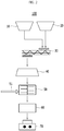
- FIG. 2 schematically illustrates a coal briquette manufacturing apparatus to which the method of manufacturing the coal briquette method illustrated in FIG. 1 .
- a structure of the coal briquette manufacturing apparatus of FIG. 2 is exemplary, and the present invention is not limited thereto.
- the structure of the coal briquette manufacturing apparatus of FIG. 2 may be variously modified.
- An apparatus for manufacturing coal briquettes 100 comprises: a powdered coal supply bin 10; an acid-treated starch powder supply bin 20; a mixer 30 supplied with powdered coal and acid-treated starch powder from the powdered coal supply bin 10 and the acid-treated starch powder supply bin 20 and mixing to prepare a coal blend; a kneader 50 provided with the coal blend from the mixer and heat treating it; and a molder 70 provided with the heat-treated coal blend from the kneader 50 and molding.
- An apparatus for manufacturing coal briquettes 100 comprises a powdered coal supply bin 10 and an acid-treated starch powder supply bin 20, the bins 10, 20 supply the powdered coal and the acid-treated starch powder.
- the powdered coal and the acid-treated starch powder are supplied to the mixer 30.
- the mixer 30 is supplied with powdered coal and acid-treated starch powder from the powdered coal supply bin and the acid-treated starch powder supply bin and mixing to prepare a coal blend.
- a preheating mixer 40 is connected to the mixer 30, so that it may preheat the coal blend at a temperature of 50 to 65 °C and mix.
- the heat treatment of the coal blend may be performed rapidly in the kneader 50 to be described later.
- the preheating mixer 40 may supply steam for heat treatment.
- the kneader 50 is provided with the coal blend from the mixer 30 or the preheating mixer 40 to carry out the heat-treatment.
- the acid-treated starch powder Due to the heat treatment in the kneader 50, the acid-treated starch powder is transformed into bio-plastic.
- the kneader 50 may be connected with a steam supply pipe 51 and be provided with steam from the steam supply pipe 51 to heat treat the coal blend.
- a plurality of steam supply pipes 51 may be installed along the vertical direction of the kneader 50.
- the plurality of steam supply pipes 51 may supply each steam of different temperatures or supply different amounts of steam according to installation positions.
- it may be configured to supply steam at a higher temperature as it goes down along the vertical direction, or to supply a large amount of steam as it goes down.
- the acid is supplied in the form of an acid-treated powder rather than in the form of an aqueous solution, unnecessary moisture in the coal blend is reduced, so that the energy for the heat treatment is reduced.
- the moisture content in the acid aqueous solution is increased, so that additional energy supply is required to convert moisture in the acid aqueous solution into water vapor in the kneader.
- the temperature for the heat treatment in the kneader 50 is not rapidly increased.
- the energy for heat treatment in the kneader 50 is reduced and the temperature for the heat treatment is also rapidly increased, so that the cut reaction for bio-plastic deformation may occur effectively and the compressive strength and the drop strength of the coal briquette may be improved as a result.
- a dryer 60 drying the heat-treated coal blend may be connected with downstream of the kneader 50.
- the dryer 60 may dry the heat-treated coal blend at a temperature of 50 to 200 °C for 3 to 10 minutes.
- the dryer 60 may spray hot blast at 70 °C or higher and a Vent is installed therein, so that all the moisture may be evaporated immediately.
- a molder 70 is provided with the heat-treated coal blend from the kneader 50 to mold it.
- the molder 70 may input the coal blend between a pair of rolls spinning in an opposite direction each other to mold to a coal briquette having a pocket or strip shape.
- the molder 70 may be operated at -5 °C or higher.
- it may be operated at room temperature.
- FIG. 3 schematically illustrates an apparatus 200 for manufacturing molten iron using the coal briquettes manufactured in FIG. 1 .
- a structure of the apparatus 200 for manufacturing molten iron of FIG. 3 is exemplary, and the present invention is not limited thereto.
- the structure of the apparatus 200 for manufacturing molten iron of FIG. 3 may be variously modified.
- the apparatus 200 for manufacturing molten iron of FIG. 3 comprises a melting and gasifying furnace 110 and a reducing furnace 120.
- furnaces Other devices may be comprised in addition to the furnaces, as necessary.
- Iron ore is inputted into and reduced in the reducing furnace 20.
- the iron ore inputted into the reducing furnace 120 is dried in advance, and then manufactured as reduced iron while passing through the reducing furnace 120.
- the reducing furnace 120 is a packed-bed reducing furnace that forms a packed bed therein by being supplied with reducing gas from the melting and gasifying furnace 110.
- the coal briquette manufactured by the method of FIG. 1 is inputted into the melting and gasifying furnace 110 and thus a coal-packed bed is formed in the melting and gasifying furnace 110.
- a dome portion 101 is formed at an upper side of the melting and gasifying furnace 110.
- the coal briquettes inputted into the dome portion 101 may be easily differentiated by the high-temperature reducing gas.
- coal briquettes manufactured by the method of FIG. 1 have high hot strength, and thus the coal briquettes are not differentiated at the dome portion of the melting and gasifying furnace 110 and fall to the lower side of the melting and gasifying furnace 110
- the char generated from thermal decomposition of coal briquette moves to the lower side of the melting and gasifying furnace 110 and then exothermically reacts with oxygen supplied through a tuyere 130.
- the coal briquette may be used as a heat source that maintains the melting and gasifying furnace 110 at a high temperature.
- lump carbon ash or coke may be inputted into the melting and gasifying furnace 110 as needed.
- the tuyere 130 is provided in an exterior wall of the melting and gasifying furnace 110 for injection of oxygen.
- Oxygen is injected into the coal-packed bed such that a combustion zone is formed.
- the coal briquette is combusted in the combustion zone to generate the reducing gas.
- FIG. 4 schematically illustrates another apparatus 300 for manufacturing molten iron using the coal briquette manufactured in FIG. 1 .
- a structure of the apparatus 300 for manufacturing molten iron of FIG. 4 is an exemplarily structure, and the present invention is not limited thereto.
- the structure of the apparatus 300 for manufacturing molten iron of FIG. 4 may be variously modified.
- the structure of the apparatus 300 for manufacturing molten iron which is illustrated in FIG. 4
- the same constituent elements are designated by the same reference numerals, and a detailed description thereof will be omitted.
- the apparatus 300 for manufacturing molten iron comprises a melting and gasifying furnace 110, a reducing furnace 122, a reduced iron compression device 140, and compressed reduced iron storage tank 150.
- the compressed reduced iron storage tank 150 may be omitted.
- the manufactured coal briquette is inputted into the melting and gasifying furnace 110
- the coal briquette generates a reducing gas in the melting and gasifying furnace 110 and the generated reducing gas is supplied to the fluidized-bed reducing furnace.
- Fine iron ores are supplied to a plurality of reducing furnaces 122 having fluidized beds and fluidized by a reducing gas supplied to the reducing furnaces 122 from the melting and gasifying furnace 110 such that reduced iron is manufactured.
- the reduced iron is compressed by the reduced iron compression device 140 and stored in the compressed reduced iron storage tank 150.
- the compressed reduced iron is inputted into the melting and gasifying furnace 110 from the compressed reduced iron storage tank 150 and then molten in the melting and gasifying furnace 110.
- the coal briquette is supplied to the melting and gasifying furnace 110 and converted into char having ventilation, and as a result, a large amount of gas generated at the lower side of the melting and gasifying furnace 110 and the compressed reduced iron more easily and uniformly pass through a coal-packed bed in the melting and gasifying furnace 110, such that molten iron with high quality may be provided.
- Starch was prepared from corn flour, and 4 parts by weight of acid-treated starch powder in the manufacturing process (pH of 4 when dissolved in 30% by volume of water) was mixed to prepare a coal blend.
- the coal blend was transferred to a preheating mixer, steam was injected into the preheating mixer, it was preheated to 50 °C or higher and mixed.
- the temperature in the kneader was adjusted to 90 °C or higher by feeding it into the kneader again.
- the amount of moisture supply in the steam was 2 parts by weight, and the kneader retention time was 15 minutes.
- the coal blend discharged from the kneader was retained for 3 to 5 minutes in a Gravity Feeder, which was a dryer, hot air at 120 °C was blown in, and then Suction was proceeded.
- the coal blend is compressed with a roll press to manufacture a coal briquette having a briquette shape and a size of 64.5 mm X 25.4 mm X 19.1 mm.
- a compressive strength and a drop strength of the coal briquette were measured according to the following evaluation method and summarized in the Table 1 below.
- a coal blend was prepared by adding an aqueous starch prepared by mixing powdered coal and 5 parts by weight of 5 wt% acetic acid solution and 4 parts by weight of starch.
- the prepared coal blend was inputted into the kneader and heat treated, and then compressed with a roll press to manufacture a coal briquette having a briquette shape and a size of 64.5 mm X 25.4 mm X 19.1 mm.
- a compressive strength and a drop strength of the coal briquette were measured according to the following evaluation method and summarized in the Table 1 below.
- the part of coal briquette of 10 g is separated and pulverized.
- the rate of change of the absorption intensity of amylose and amylopectin is measured using a UV spectrometer.
- Amylose is measured at 620 nm, and amylopectin at 540 nm.
Landscapes
- Chemical & Material Sciences (AREA)
- Life Sciences & Earth Sciences (AREA)
- Environmental & Geological Engineering (AREA)
- General Life Sciences & Earth Sciences (AREA)
- Geochemistry & Mineralogy (AREA)
- Geology (AREA)
- Oil, Petroleum & Natural Gas (AREA)
- Organic Chemistry (AREA)
- Solid Fuels And Fuel-Associated Substances (AREA)
- Polysaccharides And Polysaccharide Derivatives (AREA)
- Manufacture Of Iron (AREA)
Abstract
Description
- The present invention relates to a coal briquette and a method for manufacturing thereof.
- More particularly, the present invention relates to a briquette to which bio-plastics are applied to and a method of manufacturing the same.
- In a direct iron ore smelting reduction process, a reducing furnace for reducing iron ore and a melting and gasifying furnace for melting the reduced iron ore are used.
- When the iron ore is melted in the melting and gasifying furnace, coal briquettes, as a heat source for melting the iron ore, are inputted into the melting and gasifying furnace.
- Herein, the reduced iron is melted in the melting and gasifying furnace, converted into molten iron and slag, and then discharged to the outside.
- The coal briquettes inputted into the melting and gasifying furnace form a coal-packed bed.
- Oxygen is injected through a tuyere installed in the melting and gasifying furnace, and then combusts the coal-packed bed to generate combustion gas.
- The combustion gas is converted into high-temperature reducing gas while moving upward through the coal-packed bed.
- The high-temperature reducing gas is discharged to the outside from the melting and gasifying furnace and supplied, as reducing gas, to a reducing furnace.
- Coal briquettes are manufactured by mixing coal and a binder.
- In this case, molasses is used as a binder
- The components of the molasses vary depending on where it is sourced, and it is difficult to consistently control the ingredients according to a sugar manufacturing process.
- Therefore, in the case where a coal briquette is prepared by using molasses as a binder, it is difficult to control the quality of the coal briquette.
- Particularly, in the case of using high moisture molasses, there are problems in that the quality of the coal briquette is reduced.
- Coal briquettes using bio-plastics and a manufacturing method thereof are provided.
- The present invention relates to a method of manufacturing coal briquettes which are inputted into and quickly heated in a dome portion of a melting and gasifying furnace in an apparatus for manufacturing molten iron that comprises the melting and gasifying furnace into which reduced iron is inputted, and a reducing furnace which is connected to the melting and gasifying furnace and provides the reduced iron, the method comprises: providing powdered coal; preparing a coal blend by mixing powdered coal and acid-treated starch powder; heat treating the coal blend; and manufacturing coal briquettes by molding the heat-treated coal blend.
- In the step of preparing the coal blend, the acid-treated starch powder may be prepared by the steps comprising: pulverizing biomass; separating the remaining liquid comprising starch by immersing the pulverized biomass in an acid aqueous solution; washing the separated remaining liquid with a pH of 3 to 5.5; and drying the washed remaining liquid.
- In the step of preparing the coal blend, the pH of the acid-treated starch powder may be 3 to 5.5 when dissolved in water at a concentration of 30 % by volume.
- In the step of preparing the coal blend, an average particle size of the acid-treated starch powder may be 0.01 to 1 mm.
- In the step of preparing the coal blend, the acid-treated starch powder of 1 to 10 parts by weight may be added to the powdered coal of 100 parts by weight.
- The step of preparing the coal blend may be performed at a temperature of 50 to 65 °C.
- In the step of heat treating, the acid-treated starch powder in the coal blend may be transformed into a bio-plastic by the heat treatment.
- The step of heat treating may comprise supplying steam to the coal blend.
- The moisture in the steam may be supplied such that becomes 1 to 5 parts by weight to the powdered coal of 100 parts by weight.
- A temperature of the steam may be 120 to 300 °C.
- In the step of heat treating, a temperature of the coal blend may be 60 to 200 °C.
- Drying the heat-treated coal blend may be further comprised after the step of heat treating.
- The manufactured coal briquette may comprise 1 to 10 wt% of a bio-plastic, 3 to 15 wt% of moisture, and a balance of coal, and the bio-plastic may consist of 25 to 70 wt% of amylopectin and 30 to 75 wt% of amylose.
- An apparatus for manufacturing coal briquettes according to an example embodiment of the present invention which are inputted into and quickly heated in a dome portion of a melting and gasifying furnace in an apparatus for manufacturing molten iron that comprises the melting and gasifying furnace into which reduced iron is inputted, and a reducing furnace which is connected to the melting and gasifying furnace and provides the reduced iron,
the apparatus comprises: a powdered coal supply bin; an acid-treated starch powder supply bin; a mixer supplied with powdered coal and acid-treated starch powder from the powdered coal supply bin and the acid-treated starch powder supply bin and mixing to prepare a coal blend; a kneader provided with the coal blend from the mixer and heat treating it; and a molder provided with the heat-treated coal blend from the kneader and molding it. - A preheating mixer preheating the coal blend at a temperature of 50 to 65 °C and mixing between the mixer and the kneader may be further comprised.
- The kneader may be connected with a steam supply pipe and be provided with steam from the steam supply pipe to heat treat the coal blend.
- A dryer drying the heat-treated coal blend between the kneader and the molder may be further comprised.
- Coal briquettes having excellent strength may be manufactured.
- Since there is no K component in the binder, a pipeline clogging does not occur.
- Since quicklime or slaked lime is not used, CO2 reactivity is deteriorated, and thus fuel efficiency of coal is improved.
- Since a bending ratio of the binder is minimized, economic feasibility of the binder is improved compared with a conventional binder.
-
-
FIG. 1 is a schematic flowchart showing a method for manufacturing coal briquettes according to an example embodiment of the present invention. -
FIG. 2 is a schematic view of a coal briquette manufacturing apparatus according to an example embodiment of the present invention. -
FIG. 3 is a schematic view of an apparatus for manufacturing molten iron using the coal briquettes ofFIG. 1 . -
FIG. 4 is a schematic view of another apparatus for manufacturing molten iron using the coal briquettes ofFIG. 1 . -
FIG. 5 is a result of UV spectrometer of the binder material remaining after separating coal from coal briquettes manufactured in examples and comparative examples. - The terms first, second, third, and the like are used to describe various portions, components, regions, layers, and/or sections, but the present invention is not limited thereto.
- These terms are used only to distinguish any portion, component, region, layer, or section from other portions, components, regions, layers, or sections.
- Therefore, a first portion, component, region, layer, or section to be described below may be referred to as a second portion, component, region, layer, or section without departing from the scope of the present invention.
- The technical terms used herein are used merely for the purpose of describing a specific exemplary embodiment, and not intended to limit the present invention.
- Singular expressions used herein comprise plural expressions unless they have definitely opposite meanings.
- The terms "comprises" and/or "comprising" used in the specification specify particular features, regions, integers, steps, operations, elements, components, but do not preclude the presence or addition of other features, regions, integers, steps, operations, elements, and/or components thereof.
- Unless otherwise defined, all terms used herein comprising technical or scientific terms have the same meanings as meanings which are generally understood by those skilled in the art.
- Terms, which are usually used and defined in dictionaries, shall be construed that they have meanings matching those in the context of a related art, and shall not be construed in ideal or excessively formal meanings unless they are clearly defined in the present application.
- The present invention will be described more fully hereinafter with reference to the accompanying drawings, in which exemplary embodiments of the invention are shown.
- As those skilled in the art would realize, the described embodiments may be modified in various different ways, all without departing from the spirit or scope of the present invention.
-
FIG. 1 schematically illustrates a flowchart of a method for manufacturing coal briquettes according to an example embodiment of the present invention. - The flowchart of the method for manufacturing coal briquettes of
FIG. 1 is an exemplary flowchart, and the present invention is not limited thereto. - Thus, the manufacturing method of coal briquettes may be variously modified.
- As shown in
FIG. 1 , a method of manufacturing coal briquettes comprises: providing powdered coal (S10); preparing a coal blend by mixing powdered coal and acid-treated starch powder (S20); heat treating the coal blend (S30); and manufacturing coal briquettes by molding the heat-treated coal blend (S40). - In addition, the method of manufacturing the coal briquette may further comprise other steps as needed.
- First, in step (S10), powdered coal is provided.
- Herein, the powdered coal is prepared by pulverizing coal, and the coal is in general classified into peat comprising about 60 % of carbon powder, ignite and brown coal comprising about 70 % of carbon powder, pitch coal comprising about 70 % to 80 % of carbon powder, bituminous coal comprising about 80 % to 90 % of carbon powder, and hard coal comprising 90 % or more of carbon powder depending on a carbonization degree.
- Herein, a kind of coal is not particularly limited, but a single kind of coal or a mixture of various coals may be used.
- It is preferable to use powdered coal having a uniform particle diameter in order to reduce a deviation of quality and specifically, powdered coal having a particle diameter distribution of 80 wt% or more of a particle having a diameter of 3 mm or less, and 90 wt% or more of a particle having a diameter of 5 mm or less may be used.
- Next, in step (S20), a coal blend is prepared by mixing powdered coal and acid-treated starch powder;
- According to an example embodiment of the present invention, a mixture obtained by directly mixing an already manufactured bio-plastic with powdered coal is not applied as a binder of a coal briquette, but acid-treated starch powder, as a raw material for a bio-plastic is blended, and then, it is synthesized into a bio-plastic in a subsequent step (S30) and the like and accordingly, plays role of a coal briquette binder.
- When the already manufactured bio-plastic is directly mixed with the powdered coal, the bio-plastic may not be smoothly coated on the surface of the powdered coal and thus needs to be remelt at a high temperature.
- Herein, the remelt bio-plastic has low elastic recovery and thus deteriorates an immediate strength of a coal briquette.
- On the contrary, an example embodiment of the present invention, since the coal blend comprising the acid-treated starch as a raw material is prepared and then, used to synthesize a bio-plastic in a subsequent step (S30) and the like, the bio-plastic is smoothly coated on the surface of powdered coal, and in addition, an immediate strength of a coal briquette may be improved.
- The starch consists of 20 to 30 wt% of amylose and 70 to 80 wt% of amylopectin.
- The amylose has a linear helix structure and thus is elastic and accordingly, may be effectively coated on a medium.
- In addition, it is coated with high density and thus every efficient as a binder.
- However, the amylopectin has a branch structure and thus is hard and accordingly, may not be effectively coated on a material for binding.
- In addition, since the branch structure has low density compared with the linear structure, a coal briquette has a weak binding strength at a binder part after binding and thus is vulnerable to deformation due to an external pressure and lacks of viscoelasticity
- In an example embodiment of the present invention, when the starch is synthesized into a bio-plastic in step (S30) and the like, the amylose structure, which is advantageous as a binder, is increased, but the amylopectin structure is decreased, and thus hot strength and cold strengths of a coal briquette is improved.
- In an example embodiment of the present invention, the acid-treated starch powder comprises: pulverizing biomass; separating the remaining liquid comprising starch by immersing the pulverized biomass in an acid aqueous solution; washing the separated remaining liquid with a pH of 3 to 5.5; and drying the washed remaining liquid.
- At this time, the biomass may comprise at least one selected from the group consisting of cassava, corn, wheat, rice, barley, and potato. Specifically, corn may be used.
- When corn is used, it is immersed using a sulfurous acid solution of 0.2 to 0.5 % by volume.
- When the corn is immersed, it slowly swells as it is absorbed, and when the moisture is about 40 wt%, it becomes saturated.
- As it becomes saturated, the soluble substance in the raw material starts to elute into the immersion solution, and the lactic acid bacteria develop and the sugar eluted is fermented with lactic acid.
- Fermented lactic acid and sulfurous acid disintegrate the protein and soften the bonding between starch and protein to induce separation of starch easily.
- The corn immersed in the sulfurous acid solution is pulverized using a pulverizing machine.
- The pulverized is sent to an embryo separation tank to separate the starch.
- At this time, a rotary filter using a centrifuge may be used, and the separated starch remaining liquid is sent to the next process.
- At this time, the remaining liquid is washed to pH 3 to 5.5.
- And drying is carried out so that the moisture of 15 wt% or less is comprised.
- In this case, sulfuric acid and lactic acid will be present in some corn starch powders. The sulfuric acid may be contained 0.01 wt% or more, and the lactic acid may be contained 0.1 wt% or more.
- That is, the acid-treated starch powder may comprise 0.01 to 1 wt% of sulfuric acid and 0.1 to 1 wt% of lactic acid.
- Generally, when preparing starch, the extractant is used 100 wt% or more of the acid component in the acid aqueous solution in the step of extracting the acid from the starch.
- In an example embodiment of the present invention, since the acid-treated starch is used instead of starch, it is sufficient to use the extractant of 40 to 60 wt% of the acid component in the acid aqueous solution.
- The process of preparing the acid-treated starch in an example embodiment of the present invention is rather simple compared with the process of preparing general starch, and there is an advantage in preparing process.
- The pH of the acid-treated starch powder has to be 3 to 5.5 when dissolved in water at a concentration of 30 % by volume.
- When the pH is too high, a problem which is difficult to obtain viscoelasticity of bio-plastic appropriately may occur.
- When pH of the binder mixture is too low, viscoelasticity of a bio-plastic becomes lower, and in addition, corrosion of equipment may occur.
- Accordingly, pH may be adjusted within the above range.
- More specifically, the pH of the acid-treated starch powder may be 4 to 5 when dissolved in water at a concentration of 30 % by volume.
- An average particle size of the acid-treated starch powder may be 0.01 to 1 mm.
- When the average particle size of the acid-treated starch powder is too small, the acid-treated starch powder is aggregated each other and may not be smoothly mixed with the powdered coal.
- When the average particle size of the acid-treated starch powder is too big, it may not be smoothly mixed with the powdered coal.
- Accordingly, the average particle size of the acid-treated starch powder may be adjusted within the above range.
- For the amount of the acid-treated starch powder added, the acid-treated starch powder of 1 to 10 parts by weight may be added to the powdered coal of 100 parts by weight.
- When the amount of the acid-treated starch powder added is too large, uniformly mixing of the acid-treated starch powder and the powdered coal may become difficult.
- When the amount of the acid-treated starch powder added is too small, the binding effect may be negligible.
- Accordingly, the amount of the acid-treated starch powder added may be adjusted within the above range.
- More specifically, the acid-treated starch powder of 2 to 8 parts by weight may be added to the powdered coal of 100 parts by weight.
- The step (S20) may be performed at a temperature of 50 to 65 °C.
- When the temperature is too low, it may take a long time to increase the temperature to an appropriate heat treatment temperature in step S30 to be described later.
- When the temperature is too high, the acid-treated starch powder which is not sufficiently mixed with powdered coal may be transformed into a bio-plastic in a subsequent step (S30).
- Referring to
FIG. 1 again, the coal blend is heat treated in step (S30). - In step (S30), the acid-treated starch powder in the coal blend may be transformed into a bio-plastic by the heat treatment.
- The transformation mechanism of the acid-treated starch powder into the bio-plastic is specifically illustrated.
- Amylose and amylopectin in the starch have a crystal structure.
- The amylose has a linear structure, and the amylopectin has a structure having a branch at the amylose structure.
- When heat is applied to the amylose and amylopectin, and water is added thereto, the water is permeated into the crystal structure.
- The water may rarely be permeated among crystals at a room temperature.
- The water permeated among the crystals binds the amylose and the amylopectin through a hydrogen bonding.
- The amylopectin is cut by acid and formed into amylose.
- When the water is permeated into an amylose crystalline gap, the hydrogen bonding occurs, an OH group, a hydrophilic group, becomes outward but a C-C bonding, a hydrophobic group, becomes inward due to an interaction of the hydrophilic group and the hydrophobic group, and thus the amylose and the amylopectin are transformed into a helix structure.
- In addition, a double helix structure based on polar lipid in the starch is formed through a bonding with the polar lipid in the starch.
- The other helixes not bonded with the polar lipid are bonded themselves and also form a double helix structure.
- The amylose is shared in the double helix and forms a crystal structure when water is discharged.
- A conversion mechanism of amylopectin into amylose is as follows.
- The amylose consists of glucose through alpha 1,4-bonding.
- The amylopectin has a back-bone structure of having a main back-bone of 1,4-bonding and a branch connected to the main back-bone through alpha 1,6-bonding.
- Alpha 1,4-bonding is not cut, but α- 1,6-bonding is cut between pH 3 to 5.5 and at temperature of 60 °C or more.
- Accordingly, the α-1,6-bonding may be selectively possible under presence of acid.
- Accordingly, the branch of the amylopectin may be cut into a linear, which is similar to the amylose.
- Through such a process, a bio-plastic consisting 25 to 70 wt% of amylopectin and 30 to 75 wt% of amylose may be synthesized.
- More specifically, the bio-plastic may consist of 25 to 35 wt% of the amylopectin and 65 to 75 wt% of the amylose.
- The bio-plastic has relatively high density and thus increases a strength of a coal briquette, and in addition, since linear molecules form a helix structure, the bio-plastic may be effectively adhered on the surface of powdered coal.
- In step (S30), the step of heat treating may comprise supplying steam to the coal blend.
- By supplying steam, it is possible to supply the moisture and heat necessary for bio-plastic synthesis.
- In an example embodiment of the present invention, the acid necessary for bio-plastics synthesis is supplied in the form of an acid-treated powder rather than in the form of an aqueous solution, so that a large amount of moisture is not unnecessarily supplied.
- As a result, the moisture content in the briquettes is reduced, so that the cold strength of the briquette may be improved and unnecessary drying step may be reduced.
- Specifically, the moisture in the steam may be supplied such that becomes 1 to 5 parts by weight to the powdered coal of 100 parts by weight.
- When the moisture is supplied too small, bio-plastic synthesis may not be smoothly carried out.
- When the moisture is supplied too large, it may adversely affect the cold strength of the final manufactured coal briquette.
- Accordingly, the amount of steam may be adjusted so as to supply moisture within the above range.
- At this time, a temperature of the steam may be 120 to 300 °C.
- In step (S30), the temperature of the coal blend is increased to 60 to 200 °C due to the heat treatment.
- When the temperature of the coal blend is not increased properly, bio-plastic synthesis may not be smoothly carried out.
- After the step (S30), a step of drying the heat-treated coal blend may be further comprised.
- Specifically, the coal blend may be dried at a temperature of 50 to 200 °C for 3 to 10 minutes.
- When the drying step is further comprised, an amount of moisture may be adjusted to be comprised in a range of 3 to 15 wt% based on 100 wt% of the coal briquette.
- More specifically, it may be adjusted to be comprised in a range of 5 to 9 wt%
- Within the above range, a strength of the coal briquette may be improved.
- This moisture may be derived from the moisture present in the powdered coal in step (S10), the moisture present in the acid-treated starch powder in step (S20), and the moisture present in the steam in step (S30).
- Referring to
FIG. 1 again, coal briquettes are manufactured by molding the heat-treated coal blend in step (S40). - As not shown in
FIG. 1 , the coal blend is inputted between a pair of rolls spinning in an opposite direction each other to prepare a coal briquette having a pocket or strip shape. - As a result, a coal briquette having excellent hot and cold strengths may be prepared.
- The coal briquette manufactured by the above-described manufacturing method may comprise 1 to 10 wt% of a bio-plastic, 3 to 15 wt% of moisture, and coal in a balance amount, and the bio-plastic may comprise 25 to 70 wt% of amylopectin and 30 to 75 wt% of amylose.
- More specifically, coal briquettes may comprise 3 to 7 wt% of the bio-plastic, 5 to 9 wt% of the moisture, and a balance of coal.
- The coal briquette according to an example embodiment of the present invention has an excellent strength due to viscoelasticity of the bio-plastic.
-
FIG. 2 schematically illustrates a coal briquette manufacturing apparatus to which the method of manufacturing the coal briquette method illustrated inFIG. 1 . - A structure of the coal briquette manufacturing apparatus of
FIG. 2 is exemplary, and the present invention is not limited thereto. - Therefore, the structure of the coal briquette manufacturing apparatus of
FIG. 2 may be variously modified. - An apparatus for manufacturing
coal briquettes 100 according to an example embodiment of the present invention comprises: a powderedcoal supply bin 10; an acid-treated starchpowder supply bin 20; amixer 30 supplied with powdered coal and acid-treated starch powder from the powderedcoal supply bin 10 and the acid-treated starchpowder supply bin 20 and mixing to prepare a coal blend; akneader 50 provided with the coal blend from the mixer and heat treating it; and amolder 70 provided with the heat-treated coal blend from thekneader 50 and molding. - An apparatus for manufacturing
coal briquettes 100 according to an example embodiment of the present invention comprises a powderedcoal supply bin 10 and an acid-treated starchpowder supply bin 20, thebins - The powdered coal and the acid-treated starch powder were described above, and a duplicate description will be omitted.
- The powdered coal and the acid-treated starch powder are supplied to the
mixer 30. - The
mixer 30 is supplied with powdered coal and acid-treated starch powder from the powdered coal supply bin and the acid-treated starch powder supply bin and mixing to prepare a coal blend. - A preheating
mixer 40 is connected to themixer 30, so that it may preheat the coal blend at a temperature of 50 to 65 °C and mix. - By the presence of the preheating
mixer 40, the heat treatment of the coal blend may be performed rapidly in thekneader 50 to be described later. - The preheating
mixer 40 may supply steam for heat treatment. - The
kneader 50 is provided with the coal blend from themixer 30 or the preheatingmixer 40 to carry out the heat-treatment. - Due to the heat treatment in the
kneader 50, the acid-treated starch powder is transformed into bio-plastic. - The bio-plastic was described above, and a duplicate description will be omitted.
- The
kneader 50 may be connected with asteam supply pipe 51 and be provided with steam from thesteam supply pipe 51 to heat treat the coal blend. - A plurality of
steam supply pipes 51 may be installed along the vertical direction of thekneader 50. - The plurality of
steam supply pipes 51 may supply each steam of different temperatures or supply different amounts of steam according to installation positions. - For example, it may be configured to supply steam at a higher temperature as it goes down along the vertical direction, or to supply a large amount of steam as it goes down.
- In an example embodiment of the present invention, since the acid is supplied in the form of an acid-treated powder rather than in the form of an aqueous solution, unnecessary moisture in the coal blend is reduced, so that the energy for the heat treatment is reduced.
- For example, when the acid is supplied in the form of an acid aqueous solution, the moisture content in the acid aqueous solution is increased, so that additional energy supply is required to convert moisture in the acid aqueous solution into water vapor in the kneader.
- Also, the temperature for the heat treatment in the
kneader 50 is not rapidly increased. - As a result, the cut reaction for bio-plastic deformation does not occur effectively.
- On the other hand, in an example embodiment of the present invention, since the moisture content in the coal blend is minimized, the energy for heat treatment in the
kneader 50 is reduced and the temperature for the heat treatment is also rapidly increased, so that the cut reaction for bio-plastic deformation may occur effectively and the compressive strength and the drop strength of the coal briquette may be improved as a result. - A
dryer 60 drying the heat-treated coal blend may be connected with downstream of thekneader 50. - The
dryer 60 may dry the heat-treated coal blend at a temperature of 50 to 200 °C for 3 to 10 minutes. - The
dryer 60 may spray hot blast at 70 °C or higher and a Vent is installed therein, so that all the moisture may be evaporated immediately. - A
molder 70 is provided with the heat-treated coal blend from thekneader 50 to mold it. - The
molder 70 may input the coal blend between a pair of rolls spinning in an opposite direction each other to mold to a coal briquette having a pocket or strip shape. - The
molder 70 may be operated at -5 °C or higher. - More specifically, it may be operated at room temperature.
-
FIG. 3 schematically illustrates anapparatus 200 for manufacturing molten iron using the coal briquettes manufactured inFIG. 1 . - A structure of the
apparatus 200 for manufacturing molten iron ofFIG. 3 is exemplary, and the present invention is not limited thereto. - Therefore, the structure of the
apparatus 200 for manufacturing molten iron ofFIG. 3 may be variously modified. - The
apparatus 200 for manufacturing molten iron ofFIG. 3 comprises a melting and gasifyingfurnace 110 and a reducingfurnace 120. - Other devices may be comprised in addition to the furnaces, as necessary.
- Iron ore is inputted into and reduced in the reducing
furnace 20. - The iron ore inputted into the reducing
furnace 120 is dried in advance, and then manufactured as reduced iron while passing through the reducingfurnace 120. - The reducing
furnace 120 is a packed-bed reducing furnace that forms a packed bed therein by being supplied with reducing gas from the melting and gasifyingfurnace 110. - The coal briquette manufactured by the method of
FIG. 1 is inputted into the melting and gasifyingfurnace 110 and thus a coal-packed bed is formed in the melting and gasifyingfurnace 110. - A
dome portion 101 is formed at an upper side of the melting and gasifyingfurnace 110. - That is, a space that is wider than other portions of the melting and gasifying
furnace 110 is formed, and high-temperature reducing gas exists in the space. - Thus, the coal briquettes inputted into the
dome portion 101 may be easily differentiated by the high-temperature reducing gas. - However, coal briquettes manufactured by the method of
FIG. 1 have high hot strength, and thus the coal briquettes are not differentiated at the dome portion of the melting and gasifyingfurnace 110 and fall to the lower side of the melting and gasifyingfurnace 110 - The char generated from thermal decomposition of coal briquette moves to the lower side of the melting and gasifying
furnace 110 and then exothermically reacts with oxygen supplied through atuyere 130. - As a result, the coal briquette may be used as a heat source that maintains the melting and gasifying
furnace 110 at a high temperature. - Meanwhile, since char provides ventilation, a large amount of gas generated at the lower side of the melting and gasifying
furnace 110 and reduced iron supplied from the reducingfurnace 120 may more easily and uniformly pass through the coal-packed bed the melting and gasifyingfurnace 110 - In addition to the coal briquette, lump carbon ash or coke may be inputted into the melting and gasifying
furnace 110 as needed. - The
tuyere 130 is provided in an exterior wall of the melting and gasifyingfurnace 110 for injection of oxygen. - Oxygen is injected into the coal-packed bed such that a combustion zone is formed.
- The coal briquette is combusted in the combustion zone to generate the reducing gas.
-
FIG. 4 schematically illustrates anotherapparatus 300 for manufacturing molten iron using the coal briquette manufactured inFIG. 1 . - A structure of the
apparatus 300 for manufacturing molten iron ofFIG. 4 is an exemplarily structure, and the present invention is not limited thereto. - Therefore, the structure of the
apparatus 300 for manufacturing molten iron ofFIG. 4 may be variously modified. - Because the structure of the
apparatus 300 for manufacturing molten iron, which is illustrated inFIG. 4 , is similar to the structure of theapparatus 200 for manufacturing molten iron, which is illustrated inFIG. 3 , the same constituent elements are designated by the same reference numerals, and a detailed description thereof will be omitted. - As shown in
FIG. 4 , theapparatus 300 for manufacturing molten iron comprises a melting and gasifyingfurnace 110, a reducingfurnace 122, a reducediron compression device 140, and compressed reducediron storage tank 150. - Herein, the compressed reduced
iron storage tank 150 may be omitted. - The manufactured coal briquette is inputted into the melting and gasifying
furnace 110 - Herein, the coal briquette generates a reducing gas in the melting and gasifying
furnace 110 and the generated reducing gas is supplied to the fluidized-bed reducing furnace. - Fine iron ores are supplied to a plurality of reducing
furnaces 122 having fluidized beds and fluidized by a reducing gas supplied to the reducingfurnaces 122 from the melting and gasifyingfurnace 110 such that reduced iron is manufactured. - The reduced iron is compressed by the reduced
iron compression device 140 and stored in the compressed reducediron storage tank 150. - The compressed reduced iron is inputted into the melting and gasifying
furnace 110 from the compressed reducediron storage tank 150 and then molten in the melting and gasifyingfurnace 110. - The coal briquette is supplied to the melting and gasifying
furnace 110 and converted into char having ventilation, and as a result, a large amount of gas generated at the lower side of the melting and gasifyingfurnace 110 and the compressed reduced iron more easily and uniformly pass through a coal-packed bed in the melting and gasifyingfurnace 110, such that molten iron with high quality may be provided. - Hereinafter, the present invention will be described in further detail with reference to experimental examples.
- These experimental examples are merely for exemplifying the present invention, and the present invention is not limited thereto.
- 100 parts by weight of coal having average properties and 90 % or more of particles having a particle diameter of 3 mm or less was prepared as powdered coal (a moisture content of 10 wt% or less).
- Starch was prepared from corn flour, and 4 parts by weight of acid-treated starch powder in the manufacturing process (pH of 4 when dissolved in 30% by volume of water) was mixed to prepare a coal blend.
- The coal blend was transferred to a preheating mixer, steam was injected into the preheating mixer, it was preheated to 50 °C or higher and mixed.
- The temperature in the kneader was adjusted to 90 °C or higher by feeding it into the kneader again.
- At this time, the amount of moisture supply in the steam was 2 parts by weight, and the kneader retention time was 15 minutes.
- The coal blend discharged from the kneader was retained for 3 to 5 minutes in a Gravity Feeder, which was a dryer, hot air at 120 °C was blown in, and then Suction was proceeded.
- The coal blend is compressed with a roll press to manufacture a coal briquette having a briquette shape and a size of 64.5 mm X 25.4 mm X 19.1 mm.
- A compressive strength and a drop strength of the coal briquette were measured according to the following evaluation method and summarized in the Table 1 below.
- It was manufactured same as in Experimental Example 1 except that the amount of moisture supply in the steam was adjusted to 3 parts by weight.
- It was manufactured same as in Experimental Example 1 except that the amount of moisture supply in the steam was adjusted to 3.5 parts by weight.
- It was manufactured same as in Experimental Example 1 except that the amount of moisture supply in the steam was adjusted to 4 parts by weight.
- It was manufactured same as in Experimental Example 1 except that the kneader retention time was adjusted to 5 minutes, and the amount of moisture supply in the steam was adjusted to 3 parts by weight.
- It was manufactured same as in Experimental Example 1 except that the kneader retention time was adjusted to 10 minutes, and the amount of moisture supply in the steam was adjusted to 3 parts by weight.
- It was manufactured same as in Experimental Example 1 except that the kneader retention time was adjusted to 20 minutes, and the amount of moisture supply in the steam was adjusted to 3 parts by weight.
- 100 parts by weight of coal having average properties and a diameter of 3 mm or less was prepared as powdered coal.
- A coal blend was prepared by adding an aqueous starch prepared by mixing powdered coal and 5 parts by weight of 5 wt% acetic acid solution and 4 parts by weight of starch.
- The prepared coal blend was inputted into the kneader and heat treated, and then compressed with a roll press to manufacture a coal briquette having a briquette shape and a size of 64.5 mm X 25.4 mm X 19.1 mm.
- A compressive strength and a drop strength of the coal briquette were measured according to the following evaluation method and summarized in the Table 1 below.
- The part of coal briquette of 10 g is separated and pulverized.
- Next, it is precipitated in ethanol for more than one day and then filtered. The obtained solution is concentrated using a rotary evaporator. Then it is diluted with 10 mL of water. And then 1 to 2 drops of iodine solution is dropped.
- The rate of change of the absorption intensity of amylose and amylopectin is measured using a UV spectrometer.
- Amylose is measured at 620 nm, and amylopectin at 540 nm.
- In case of Experimental Example 1 (X marked), Experimental Example 2 (○ marked) and Experimental Example 3 (□ marked) in
FIG. 5 , when amylose / amylopectin is mixed to be used, it may be confirmed that the higher the amylose level, the closer to the amylose absorption curve, and the bioplastic was formed in coal briquette. - On the other hand, in the case of the Comparative Example (Δ marked), it may be confirmed that it present to be close to the absorption curve of amylopectin so that bio-plastics are not formed, and it remained in the form of starch.
- 30 coal briquettes manufactured according to Experimental Examples 1 to 7 and Comparative Example were respectively fixed at the lower side, and a maximum load was measured by compressing from top at a constant speed until broken and then, the average value was represented.
- The coal briquettes according to Experimental Examples 1 to 7 and Comparative Example were respectively 4 times dropped from 5 m high to the ground and then, a ratio of a weight of the coal briquette maintaining the shape which has a particle diameter of 10 mm or more was represented as a percentage with respect to an entire weight of the coal briquette.
- The experiment results of the coal briquettes manufactured in Experimental Examples 1 to 7 and Comparative Example are summarized and shown in Table 1.
[Table 1] Kneader retention time (min) 15 15 15 15 5 10 20 15 Aqueous starch Acid aqueous solution (parts by weight) - - - - - - - 5 Starch (parts by weight) - - - - - - - 4 Acid-treated starch (parts by weight) 4 4 4 4 4 4 4 - Moisture supply by steam (parts by weight) 2 3 3.5 4 3 3 3 - Compressive strength (kgf) 58.7 62.0 58.1 56.4 56.3 58.5 65.3 52.1 Drop strength (%) 95.4 96.6 96.1 97.4 96.4 90.8 96.3 90.1 - As shown in Table 1, it was confirmed that the strengths of the briquettes manufactured in Experimental Examples 1 to 7 were excellent compared with those of Comparative Example using Aqueous starch.
- The present invention is not limited to the example embodiments and may be embodied in various modifications, and it will be understood by a person of ordinary skill in the art to which the present invention pertains that the present invention may be carried out through other specific embodiments without modifying the technical idea or essential characteristics thereof.
- Therefore, the aforementioned embodiments should be understood to be exemplary but not limiting the present invention in any way.
-
- 10:
- Powdered coal supply bin
- 20:
- Acid-treated starch powder supply bin
- 30:
- Mixer
- 40:
- Preheating mixer
- 50:
- Kneader
- 60:
- Dryer
- 70:
- Molder
- 100:
- Apparatus for manufacturing coal briquettes
- 110:
- Melting and gasifying furnace
- 120, 122:
- Reducing furnace
- 130:
- Tuyere
- 140:
- Reduced iron compression device
- 150:
- Compressed reduced iron storage tank
- 200, 300:
- Apparatus for manufacturing molten iron
- 101:
- Dome portion
Claims (17)
- A method of manufacturing coal briquettes which are inputted into and quickly heated in a dome portion of a melting and gasifying furnace in an apparatus for manufacturing molten iron that comprises the melting and gasifying furnace into which reduced iron is inputted, and a reducing furnace which is connected to the melting and gasifying furnace and provides the reduced iron, the method comprising:providing powdered coal;preparing a coal blend by mixing powdered coal and acid-treated starch powder;heat treating the coal blend; andmanufacturing coal briquettes by molding the heat-treated coal blend.
- The method of claim 1, wherein
in the step of preparing the coal blend, the acid-treated starch powder is prepared by the steps comprising: pulverizing biomass; separating the remaining liquid comprising starch by immersing the pulverized biomass in an acid aqueous solution; washing the separated remaining liquid with a pH of 3 to 5.5; and drying the washed remaining liquid. - The method of claim 1, wherein
in the step of preparing the coal blend, the pH of the acid-treated starch powder is 3 to 5.5 when dissolved in water at a concentration of 30 % by volume. - The method of claim 1, wherein
in the step of preparing the coal blend, an average particle size of the acid-treated starch powder is 0.01 to 1 mm. - The method of claim 1, wherein
in the step of preparing the coal blend, the acid-treated starch powder of 1 to 10 parts by weight are added to the powdered coal of 100 parts by weight. - The method of claim 1, wherein
the step of preparing the coal blend is performed at a temperature of 50 to 65 °C. - The method of claim 1, wherein
in the step of heat treating, the acid-treated starch powder in the coal blend is transformed into a bio-plastic by the heat treatment. - The method of claim 1, wherein
the step of heat treating comprises supplying steam to the coal blend. - The method of claim 8, wherein
the moisture in the steam is supplied such that becomes 1 to 5 parts by weight to the powdered coal of 100 parts by weight. - The method of claim 8, wherein
a temperature of the steam is 120 to 300 °C. - The method of claim 1, wherein
in the step of heat treating, a temperature of the coal blend is 60 to 200 °C. - The method of claim 1, further comprising
drying the heat-treated coal blend after the step of heat treating. - The method of claim 1, wherein
the manufactured coal briquette comprises 1 to 10 wt% of a bio-plastic, 3 to 15 wt% of moisture, and a balance of coal, and the bio-plastic consists of 25 to 70 wt% of amylopectin and 30 to 75 wt% of amylose. - An apparatus for manufacturing coal briquettes which are inputted into and quickly heated in a dome portion of a melting and gasifying furnace in an apparatus for manufacturing molten iron that comprises the melting and gasifying furnace into which reduced iron is inputted, and a reducing furnace which is connected to the melting and gasifying furnace and provides the reduced iron, the apparatus comprising:a powdered coal supply bin;an acid-treated starch powder supply bin;a mixer supplied with powdered coal and acid-treated starch powder from the powdered coal supply bin and the acid-treated starch powder supply bin and mixing to prepare a coal blend;a kneader provided with the coal blend from the mixer and heat treating it; anda molder provided with the heat-treated coal blend from the kneader and molding it.
- The apparatus of claim 14, further comprising
a preheating mixer preheating the coal blend at a temperature of 50 to 65 °C and mixing between the mixer and the kneader. - The apparatus of claim 14, wherein
the kneader is connected with a steam supply pipe and is provided with steam from the steam supply pipe to heat treat the coal blend. - The apparatus of claim 14, wherein
a dryer drying the heat-treated coal blend between the kneader and the molder.
Applications Claiming Priority (2)
| Application Number | Priority Date | Filing Date | Title |
|---|---|---|---|
| KR1020160132392A KR101827997B1 (en) | 2016-10-12 | 2016-10-12 | Method and apparatus for manufacturing coal briquettes |
| PCT/KR2017/010251 WO2018070681A1 (en) | 2016-10-12 | 2017-09-19 | Method for manufacturing briquette and apparatus for manufacturing briquette |
Publications (2)
| Publication Number | Publication Date |
|---|---|
| EP3527646A1 true EP3527646A1 (en) | 2019-08-21 |
| EP3527646A4 EP3527646A4 (en) | 2019-10-23 |
Family
ID=61231877
Family Applications (1)
| Application Number | Title | Priority Date | Filing Date |
|---|---|---|---|
| EP17860281.9A Withdrawn EP3527646A4 (en) | 2016-10-12 | 2017-09-19 | Method for manufacturing briquette and apparatus for manufacturing briquette |
Country Status (4)
| Country | Link |
|---|---|
| EP (1) | EP3527646A4 (en) |
| KR (1) | KR101827997B1 (en) |
| CN (1) | CN109804052A (en) |
| WO (1) | WO2018070681A1 (en) |
Cited By (1)
| Publication number | Priority date | Publication date | Assignee | Title |
|---|---|---|---|---|
| JP2022112263A (en) * | 2021-01-21 | 2022-08-02 | Jfeスチール株式会社 | How to make briquettes |
Families Citing this family (2)
| Publication number | Priority date | Publication date | Assignee | Title |
|---|---|---|---|---|
| KR102104556B1 (en) * | 2018-08-10 | 2020-04-24 | 주식회사 포스코 | Method and apparatus for manufacturing of coal briquettes |
| KR102311318B1 (en) * | 2019-11-07 | 2021-10-08 | 주식회사 포스코 | Coal briquettes, and method for manufacturing the same |
Family Cites Families (14)
| Publication number | Priority date | Publication date | Assignee | Title |
|---|---|---|---|---|
| DE1072588B (en) * | 1955-01-13 | 1960-01-07 | ||
| US1009961A (en) * | 1911-01-18 | 1911-11-28 | Edward H Ellis | Fuel-briquet and method of making same. |
| US2890945A (en) * | 1954-04-26 | 1959-06-16 | Briko Nv | Process of manufacturing briquettes |
| CN1023022C (en) * | 1988-12-22 | 1993-12-08 | 中国科学院山西煤炭化学研究所 | Method for preparing briquette |
| CN1043521C (en) | 1993-04-03 | 1999-06-02 | 刘传书 | Method and apparatus for tower wet production process of concentrated phosphoric acid |
| CN1173018C (en) * | 2000-12-19 | 2004-10-27 | Posco公司 | Briquette with excellent strength and briquette making process |
| JP4926671B2 (en) * | 2006-11-30 | 2012-05-09 | 新日本製鐵株式会社 | Coal oven coal pretreatment method and apparatus |
| KR101031933B1 (en) | 2010-12-10 | 2011-04-29 | 김동덕 | Method of manufacturing coal briquettes using alpha starch |
| KR101418053B1 (en) * | 2012-12-21 | 2014-07-09 | 주식회사 포스코 | Coal briquettes and method for manufacturing the same |
| KR101565506B1 (en) * | 2013-12-26 | 2015-11-03 | 주식회사 포스코 | Method for manufacturing a binder for being used in a coal briquette and method for manufacturing the coal briquette comprising the same |
| KR101739858B1 (en) * | 2014-12-18 | 2017-05-25 | 주식회사 포스코 | Coal briquettes, method and apparatus for manufacturing the same |
| KR101634069B1 (en) * | 2014-12-23 | 2016-06-28 | 주식회사 포스코 | Coal briquettes and method for manufacturing the same |
| KR101728824B1 (en) * | 2014-12-23 | 2017-04-20 | 주식회사 포스코 | Method for manufacturing coal briquettes, and the device |
| KR101797738B1 (en) * | 2015-12-09 | 2017-11-15 | 주식회사 포스코 | Coal briquettes and method for manufacturing the same |
-
2016
- 2016-10-12 KR KR1020160132392A patent/KR101827997B1/en active Active
-
2017
- 2017-09-19 WO PCT/KR2017/010251 patent/WO2018070681A1/en not_active Ceased
- 2017-09-19 CN CN201780063205.6A patent/CN109804052A/en active Pending
- 2017-09-19 EP EP17860281.9A patent/EP3527646A4/en not_active Withdrawn
Cited By (1)
| Publication number | Priority date | Publication date | Assignee | Title |
|---|---|---|---|---|
| JP2022112263A (en) * | 2021-01-21 | 2022-08-02 | Jfeスチール株式会社 | How to make briquettes |
Also Published As
| Publication number | Publication date |
|---|---|
| CN109804052A (en) | 2019-05-24 |
| WO2018070681A1 (en) | 2018-04-19 |
| KR101827997B1 (en) | 2018-02-13 |
| WO2018070681A8 (en) | 2018-05-17 |
| EP3527646A4 (en) | 2019-10-23 |
Similar Documents
| Publication | Publication Date | Title |
|---|---|---|
| US6605130B2 (en) | Pellets incorporated with carbonaceous material | |
| JP2768888B2 (en) | Direct reduction method of fine iron oxide-containing material and production equipment for performing the method | |
| CN103547656B (en) | Apparatus and method for drying coking coal | |
| BRPI0918140B1 (en) | PROCESS FOR THE PRODUCTION OF FINALLY PARTICULATED IRON CONDUCTOR AGGLOMERATES | |
| KR20180129857A (en) | Method for producing binder-free coal-based activated carbon | |
| KR101827997B1 (en) | Method and apparatus for manufacturing coal briquettes | |
| KR101797738B1 (en) | Coal briquettes and method for manufacturing the same | |
| CN103627895A (en) | Production method for sintering chromium powder ore by continuous strand sinter machine | |
| EP2859128B1 (en) | Process for producing hardened granules from iron-containing particles | |
| CN1109911A (en) | Method for producing spongy iron by coal-base gas-making in vertical furnace | |
| EP3363880A1 (en) | Coal briquettes and method for manufacturing same | |
| TWI550100B (en) | Process for the manufacture of ferrochrome | |
| EP3650520A1 (en) | Method for producing coal briquette, and coal briquette produced by same | |
| KR20160074346A (en) | Coal briquettes, method and apparatus for manufacturing the same | |
| JP4077212B2 (en) | Briquette for recovering valuable metals in steelmaking by-products for electric smelting furnace and method for producing the same | |
| JP2022083866A (en) | Oxidized ore smelting method | |
| WO2017043725A1 (en) | Coal briquette, method for producing same, and method for producing molten iron | |
| KR101696628B1 (en) | Coal briquettes, method and apparatus for manufacturing the same, and method for manufacturing molten iron | |
| NO159968B (en) | INSTALLATION SYSTEM WITH SKETCH CONTACT. | |
| KR102311318B1 (en) | Coal briquettes, and method for manufacturing the same | |
| JP2007169780A (en) | Method for producing sintered ore | |
| KR101634069B1 (en) | Coal briquettes and method for manufacturing the same | |
| JPH0948977A (en) | Blast furnace coke manufacturing method | |
| KR20190078426A (en) | Coal briquettes and method for manufacturing the same | |
| CN105883802A (en) | Coal-based activated carbon preparation method based on external heating type rotary furnace carbonization |
Legal Events
| Date | Code | Title | Description |
|---|---|---|---|
| STAA | Information on the status of an ep patent application or granted ep patent |
Free format text: STATUS: THE INTERNATIONAL PUBLICATION HAS BEEN MADE |
|
| PUAI | Public reference made under article 153(3) epc to a published international application that has entered the european phase |
Free format text: ORIGINAL CODE: 0009012 |
|
| STAA | Information on the status of an ep patent application or granted ep patent |
Free format text: STATUS: REQUEST FOR EXAMINATION WAS MADE |
|
| 17P | Request for examination filed |
Effective date: 20190412 |
|
| AK | Designated contracting states |
Kind code of ref document: A1 Designated state(s): AL AT BE BG CH CY CZ DE DK EE ES FI FR GB GR HR HU IE IS IT LI LT LU LV MC MK MT NL NO PL PT RO RS SE SI SK SM TR |
|
| AX | Request for extension of the european patent |
Extension state: BA ME |
|
| A4 | Supplementary search report drawn up and despatched |
Effective date: 20190920 |
|
| RIC1 | Information provided on ipc code assigned before grant |
Ipc: C10L 5/06 20060101AFI20190916BHEP Ipc: C10L 5/22 20060101ALI20190916BHEP Ipc: C10L 5/04 20060101ALI20190916BHEP Ipc: C10L 5/14 20060101ALI20190916BHEP Ipc: C10L 5/36 20060101ALI20190916BHEP |
|
| DAV | Request for validation of the european patent (deleted) | ||
| DAX | Request for extension of the european patent (deleted) | ||
| STAA | Information on the status of an ep patent application or granted ep patent |
Free format text: STATUS: THE APPLICATION IS DEEMED TO BE WITHDRAWN |
|
| 18D | Application deemed to be withdrawn |
Effective date: 20210401 |