EP3527490B1 - Aircraft with engine assembly mounted to wheel well - Google Patents
Aircraft with engine assembly mounted to wheel well Download PDFInfo
- Publication number
- EP3527490B1 EP3527490B1 EP19158136.2A EP19158136A EP3527490B1 EP 3527490 B1 EP3527490 B1 EP 3527490B1 EP 19158136 A EP19158136 A EP 19158136A EP 3527490 B1 EP3527490 B1 EP 3527490B1
- Authority
- EP
- European Patent Office
- Prior art keywords
- assembly
- engine
- wheel well
- gearbox
- aircraft
- Prior art date
- Legal status (The legal status is an assumption and is not a legal conclusion. Google has not performed a legal analysis and makes no representation as to the accuracy of the status listed.)
- Active
Links
- 238000002485 combustion reaction Methods 0.000 claims description 32
- 238000004891 communication Methods 0.000 claims description 11
- 239000012530 fluid Substances 0.000 claims description 11
- 238000000034 method Methods 0.000 claims description 3
- 230000000284 resting effect Effects 0.000 claims 1
- 238000001816 cooling Methods 0.000 description 77
- 239000000314 lubricant Substances 0.000 description 23
- 239000002826 coolant Substances 0.000 description 17
- 230000000712 assembly Effects 0.000 description 10
- 238000000429 assembly Methods 0.000 description 10
- 238000013329 compounding Methods 0.000 description 9
- 239000012809 cooling fluid Substances 0.000 description 7
- 239000007788 liquid Substances 0.000 description 5
- 150000001875 compounds Chemical class 0.000 description 3
- 239000007789 gas Substances 0.000 description 3
- 239000003921 oil Substances 0.000 description 2
- 238000011144 upstream manufacturing Methods 0.000 description 2
- 239000005068 cooling lubricant Substances 0.000 description 1
- 238000000605 extraction Methods 0.000 description 1
- 238000009434 installation Methods 0.000 description 1
- 239000010687 lubricating oil Substances 0.000 description 1
- 238000005461 lubrication Methods 0.000 description 1
- 239000010705 motor oil Substances 0.000 description 1
- 238000011084 recovery Methods 0.000 description 1
- XLYOFNOQVPJJNP-UHFFFAOYSA-N water Substances O XLYOFNOQVPJJNP-UHFFFAOYSA-N 0.000 description 1
Images


Classifications
-
- B—PERFORMING OPERATIONS; TRANSPORTING
- B64—AIRCRAFT; AVIATION; COSMONAUTICS
- B64D—EQUIPMENT FOR FITTING IN OR TO AIRCRAFT; FLIGHT SUITS; PARACHUTES; ARRANGEMENTS OR MOUNTING OF POWER PLANTS OR PROPULSION TRANSMISSIONS IN AIRCRAFT
- B64D27/00—Arrangement or mounting of power plant in aircraft; Aircraft characterised thereby
- B64D27/02—Aircraft characterised by the type or position of power plant
- B64D27/04—Aircraft characterised by the type or position of power plant of piston type
- B64D27/08—Aircraft characterised by the type or position of power plant of piston type within or attached to fuselage
-
- B—PERFORMING OPERATIONS; TRANSPORTING
- B64—AIRCRAFT; AVIATION; COSMONAUTICS
- B64C—AEROPLANES; HELICOPTERS
- B64C25/00—Alighting gear
- B64C25/02—Undercarriages
- B64C25/08—Undercarriages non-fixed, e.g. jettisonable
- B64C25/10—Undercarriages non-fixed, e.g. jettisonable retractable, foldable, or the like
- B64C25/14—Undercarriages non-fixed, e.g. jettisonable retractable, foldable, or the like fore-and-aft
-
- B—PERFORMING OPERATIONS; TRANSPORTING
- B64—AIRCRAFT; AVIATION; COSMONAUTICS
- B64C—AEROPLANES; HELICOPTERS
- B64C25/00—Alighting gear
- B64C25/02—Undercarriages
- B64C25/08—Undercarriages non-fixed, e.g. jettisonable
- B64C25/10—Undercarriages non-fixed, e.g. jettisonable retractable, foldable, or the like
- B64C25/16—Fairings movable in conjunction with undercarriage elements
-
- B—PERFORMING OPERATIONS; TRANSPORTING
- B64—AIRCRAFT; AVIATION; COSMONAUTICS
- B64C—AEROPLANES; HELICOPTERS
- B64C25/00—Alighting gear
- B64C25/32—Alighting gear characterised by elements which contact the ground or similar surface
- B64C25/34—Alighting gear characterised by elements which contact the ground or similar surface wheeled type, e.g. multi-wheeled bogies
-
- B64D27/026—
-
- B64D27/40—
-
- B—PERFORMING OPERATIONS; TRANSPORTING
- B64—AIRCRAFT; AVIATION; COSMONAUTICS
- B64D—EQUIPMENT FOR FITTING IN OR TO AIRCRAFT; FLIGHT SUITS; PARACHUTES; ARRANGEMENTS OR MOUNTING OF POWER PLANTS OR PROPULSION TRANSMISSIONS IN AIRCRAFT
- B64D29/00—Power-plant nacelles, fairings, or cowlings
- B64D29/04—Power-plant nacelles, fairings, or cowlings associated with fuselages
-
- B—PERFORMING OPERATIONS; TRANSPORTING
- B64—AIRCRAFT; AVIATION; COSMONAUTICS
- B64D—EQUIPMENT FOR FITTING IN OR TO AIRCRAFT; FLIGHT SUITS; PARACHUTES; ARRANGEMENTS OR MOUNTING OF POWER PLANTS OR PROPULSION TRANSMISSIONS IN AIRCRAFT
- B64D33/00—Arrangements in aircraft of power plant parts or auxiliaries not otherwise provided for
- B64D33/08—Arrangements in aircraft of power plant parts or auxiliaries not otherwise provided for of power plant cooling systems
-
- B—PERFORMING OPERATIONS; TRANSPORTING
- B64—AIRCRAFT; AVIATION; COSMONAUTICS
- B64D—EQUIPMENT FOR FITTING IN OR TO AIRCRAFT; FLIGHT SUITS; PARACHUTES; ARRANGEMENTS OR MOUNTING OF POWER PLANTS OR PROPULSION TRANSMISSIONS IN AIRCRAFT
- B64D35/00—Transmitting power from power plant to propellers or rotors; Arrangements of transmissions
- B64D35/02—Transmitting power from power plant to propellers or rotors; Arrangements of transmissions characterised by the type of power plant
-
- F—MECHANICAL ENGINEERING; LIGHTING; HEATING; WEAPONS; BLASTING
- F02—COMBUSTION ENGINES; HOT-GAS OR COMBUSTION-PRODUCT ENGINE PLANTS
- F02B—INTERNAL-COMBUSTION PISTON ENGINES; COMBUSTION ENGINES IN GENERAL
- F02B41/00—Engines characterised by special means for improving conversion of heat or pressure energy into mechanical power
- F02B41/02—Engines with prolonged expansion
- F02B41/10—Engines with prolonged expansion in exhaust turbines
-
- F—MECHANICAL ENGINEERING; LIGHTING; HEATING; WEAPONS; BLASTING
- F02—COMBUSTION ENGINES; HOT-GAS OR COMBUSTION-PRODUCT ENGINE PLANTS
- F02B—INTERNAL-COMBUSTION PISTON ENGINES; COMBUSTION ENGINES IN GENERAL
- F02B53/00—Internal-combustion aspects of rotary-piston or oscillating-piston engines
- F02B53/14—Adaptations of engines for driving, or engine combinations with, other devices
-
- F—MECHANICAL ENGINEERING; LIGHTING; HEATING; WEAPONS; BLASTING
- F02—COMBUSTION ENGINES; HOT-GAS OR COMBUSTION-PRODUCT ENGINE PLANTS
- F02B—INTERNAL-COMBUSTION PISTON ENGINES; COMBUSTION ENGINES IN GENERAL
- F02B53/00—Internal-combustion aspects of rotary-piston or oscillating-piston engines
- F02B2053/005—Wankel engines
Definitions
- the application relates generally to aircraft engines and, more particularly, to engine assemblies for driving propellers.
- Engine assemblies mounted in the nose or wing of aircraft are typically supported on the bulkhead at the structural interface between the engine compartment and the airframe structure.
- a retractable landing gear it is known to install the engine in front of the landing gear compartment. It is also known to locate the engine oil cooler in front of the engine, in a duct directing cooling air through the oil cooler.
- US 3 028 124 A discloses a prior art mounting system of aircraft power plants.
- an assembly for an aircraft having a propeller comprising: a wheel well configured for receiving a retracted landing gear, the wheel well including walls and a closable bottom opening for deploying the landing gear therethrough; an engine assembly having an engine shaft configured for driving engagement with the propeller; and a mount assembly for supporting the engine assembly, the mount assembly connected to at least one of the walls of the wheel well.
- the engine assembly includes combustion engine in driving engagement with the engine shaft, and a gearbox drivingly engaged to the engine shaft, the mount assembly interconnecting a casing of the gearbox to at least one of the walls of the wheel well.
- an engine assembly 10 is generally shown and includes an internal combustion engine 12.
- the engine assembly 10 is a compound cycle engine system or compound cycle engine such as described in Lents et al.'s US patent No. 7,753,036 issued July 13, 2010 or as described in Julien et al.'s US patent No. 7,775,044 issued August 17, 2010 , or as described in Thomassin et al.'s U.S. patent publication No. 2015/0275749 published October 1, 2015 , or as described in Bolduc et al.'s U.S. patent publication No. 2015/0275756 published October 1, 2015 .
- the engine assembly may be used as a prime mover engine on an aircraft.
- the internal combustion engine 12 is an intermittent internal combustion engine including one or more rotor assembly(ies), for example three rotor assemblies, each configured for example as a Wankel engine; it is understood that the internal combustion engine 12 may have any other suitable configuration, for example including one or more reciprocating pistons.
- the internal combustion engine 12 drives an engine shaft 14 that is drivingly engaged to a propeller shaft 16 via a reduction gearbox 18 so as to drive an aircraft propeller 20.
- the engine assembly 10 may additionally be configured to drive any other appropriate type of load, including, but not limited to, one or more generator(s), accessory(ies), rotor mast(s), compressor(s), or any other appropriate type of load or combination thereof.
- the engine assembly 10 also includes a compressor 22 for compressing the air before it is fed to an intake 12i of the internal combustion engine 12.
- the engine intake 12i may for example correspond to or communicate with the inlet port of each rotor assembly or reciprocating piston of the internal combustion engine 12.
- An inlet plenum or scroll 24 is fluidly connected to a source of air, for example an environment of the aircraft, via a suitable inlet conduit 25, and is in fluid communication with an inlet 22i of the compressor 22.
- An outlet 22o of the compressor 22 is in fluid communication with the air intake 12i of the internal combustion engine 12, for example via a suitable conduit 26.
- the engine assembly 10 further includes a turbine section 28 receiving the exhaust gases from the internal combustion engine 12, for example an exhaust flow of high pressure hot gas exiting at high peak velocity in the form of exhaust pulses.
- an exhaust 12o of the internal combustion engine 12 is in fluid communication with an inlet 28i of the turbine section 28 via a suitable conduit 30.
- the exhaust 12o of the internal combustion engine 12 may for example correspond to or communicate with the exhaust port of each rotor assembly or reciprocating piston of the internal combustion engine 12.
- the turbine section 28 comprises two turbine stages 32, 34 in serial fluid communication with each other, so that the inlet of the first turbine stage 32 defines the inlet 28i of the turbine section 28 communicating with the exhaust 12o of the internal combustion engine 12, and an outlet 32o of the first turbine stage 32 communicates with an inlet 34i of the second turbine stage 34.
- Other configurations are contemplated.
- the flow of exhaust gases exits an outlet 28o of the turbine section 28 (e.g. an outlet of the second turbine stage 34), for example via an exhaust conduit 36 connected to the outlet 28o of the turbine section 28 and in fluid communication with the environment of the aircraft (i.e. with atmosphere).
- the engine shaft 14, the compressor 22 and the turbine section 28 are in driving engagement with each other via a compounding gearbox 38.
- the gearbox 38 is configured to allow the turbine section 28 to compound power with the engine shaft 14 and to allow the turbine section 28 and/or the internal combustion engine 12 to drive the compressor 22.
- the gearbox 38 may also be drivingly engaged to engine accessories (not shown).
- the turbine section 28 includes a turbine shaft 40, to which the rotors of the turbine section 28 are connected.
- the turbine shaft 40 extends through the gearbox 38 and also receives the rotor(s) of the compressor 22.
- the turbine shaft 40 is drivingly engaged to the engine shaft 14 via the gearbox 38.
- the power from the turbine shaft 40 and engine shaft 14 is compounded by the gearbox 38 to drive the propeller 20 and the compressor 22.
- any other suitable manner of compounding power from the turbine shaft 40 with power from the engine shaft 14 mal alternately be used, including, but not limited to, a driving engagement between the turbine shaft 40 and the engine shaft 14 via the reduction gearbox 18 (see e.g. Figs. 7-9 discussed further below), electrical compounding via power transfer between generators connected to the independently rotatable shafts, etc.
- the turbine shaft 40 and engine shaft 14 are parallel to and offset from each other. Other configurations are also possible.
- the engine assembly 10 also includes a first heat exchanger 42 configured as a coolant cooler.
- the heat exchanger 42 has one or more coolant conduits fluidly connected to a coolant circulation system 44, which is fluidly connected to the internal combustion engine 12 to circulate a cooling fluid therein. Accordingly, the heat exchanger 42 is configured to receive and cool the cooling fluid circulated out of the internal combustion engine 12 before the cooling fluid is circulated back to the internal combustion engine 12.
- the heat exchanger 42 further includes one or more air conduits configured for circulation of cooling air therethrough, with the air conduit(s) and coolant conduit(s) being in heat exchange relationship with each other so that circulation of cooling air through the cooling conduit(s) provides cooling of the cooling fluid circulating through the coolant conduit(s).
- the cooling fluid may be a suitable liquid coolant, for example a suitable water-based coolant.
- the coolant circulation system 44 includes one or more pump(s) or any other suitable mechanism for driving the circulation of the cooling fluid through the coolant circulation system 44, including between the internal combustion engine 12 and the heat exchanger 42.
- the engine assembly 10 further includes a second heat exchanger 46 configured as a lubricant cooler.
- the second heat exchanger 46 has one or more lubricant conduits fluidly connected to a lubricant circulation system 48 of the engine assembly 10.
- the lubricant circulation system 48 is fluidly connected to one or more components of the engine assembly 10 to circulate a lubricant thereto; in the embodiment shown, the lubricant circulation system 48 is connected to the gearbox 38, and the gearbox 38 includes a casing which may also contain bearings supporting the shafts 14, 40 and may therefore act as or include one or more bearing housing(s) also receiving the lubricant.
- the second heat exchanger 46 is configured to receive and cool the lubricant before the lubricant is circulated back to the component(s) of the engine assembly 10.
- the second heat exchanger 46 further includes one or more air conduits configured for circulation of cooling air therethrough, with the air conduit(s) and lubricant conduit(s) being in heat exchange relationship with each other so that circulation of cooling air through the cooling conduit(s) provides cooling of the lubricant circulating through the lubricant conduit(s).
- the lubricant may be a suitable liquid lubricant, for example a suitable type of oil.
- the lubricant circulation system 48 includes one or more pump(s) or any other suitable mechanism for driving the circulation of the lubrication through the lubricant circulation system 48, including between the component(s) of the engine assembly 10 and the second heat exchanger 46.
- each heat exchanger 42, 46 is shown as being connected to the respective circulation system 44, 48 without being connected to the other, it is understood that other configurations are also possible.
- one or both of the heat exchanger 42, 46 may be connected to both the coolant and lubricant circulation systems 44, 48, including one or more conduits for receiving the coolant and one or more conduits for receiving the lubricant, each in heat exchange relationship with the one or more conduits through which the cooling airflow circulates; the coolant conduit(s) and lubricant conduit(s) may also be in heat exchange relationship with each other.
- an assembly 50 configured as a nose assembly for a front end of an aircraft and including the engine assembly 10 is generally shown.
- the nose assembly 50 is received in a front or nose nacelle 52 of the aircraft: the reduction gearbox 18 is connected to the front of the internal combustion engine 12 (as shown, including three rotor assemblies each configured as a Wankel engine), the compounding gearbox 38 is connected to the rear of the internal combustion engine 12, the turbine section 28 is connected to the compounding gearbox 38 and extends side-by-side with the internal combustion engine 12, and the compressor 22 is located aft of the turbine section 28.
- the reduction gearbox 18 is connected to the front of the internal combustion engine 12 (as shown, including three rotor assemblies each configured as a Wankel engine)
- the compounding gearbox 38 is connected to the rear of the internal combustion engine 12
- the turbine section 28 is connected to the compounding gearbox 38 and extends side-by-side with the internal combustion engine 12
- the compressor 22 is located aft of the turbine section 28.
- the assembly 50 includes a wheel well 54 located under the engine assembly 10, and configured for receiving a retractable landing gear 56 (see Fig. 4 ) when in a retracted configuration.
- the wheel well 54 has a plurality of interconnected walls which form a box for containing the landing gear 56 when retracted: side walls 54s, a front wall and a rear wall together defining a perimeter which in the embodiment shown is rectangular, and a top wall 54t ( Fig. 2 ) connected to the side, front and rear walls so as to close the top of the box.
- the wheel well 54 has a selectively closable bottom opening opposed to the top wall 54t, for deploying the retractable landing gear 56 therethrough.
- a pivotable door 58 selectively closes the bottom opening of the wheel well 54, with the door 58 being pivotally connected to the aircraft (e.g. to one of the side, front and rear walls of the wheel well 54).
- Other configurations are possible.
- the assembly 50 further includes cooling ducts feeding cooling air to the heat exchangers 42, 46: the first, e.g. coolant, heat exchanger 42 is positioned and configured for receiving a cooling airflow from the first cooling duct 60, and the second, e.g. lubricant, heat exchanger 46 is positioned and configured for receiving a cooling airflow from the second cooling duct 62.
- the first heat exchanger 42 is received in the first cooling duct 60 and the second heat exchanger 46 is received in the second cooling duct 62.
- Each heat exchanger 42, 46 extends across the respective cooling duct 60, 62 so that all of the airflow circulating through each cooling duct 60, 62 circulates through the heat exchanger 42, 46 received therein.
- the cooling ducts 60, 62 extend on respective sides of the wheel well 54, so that the wheel well 54 is located between the heat exchangers 42, 46, as can be best seen in Fig. 2 .
- the internal combustion engine 12, compressor 22 and turbine section 28 are all located between the two cooling ducts 60, 62.
- the heat exchangers 42, 46 are located closer to the outlet of the cooling ducts 60, 62 than to their inlets.
- the heat exchangers 42, 46 define a rearmost portion of the engine assembly 10: the heat exchangers 42, 46 are located aft of the internal combustion engine 12, compressor 22, and turbine section 28.
- the cooling ducts 60, 62 each have a front inlet 60i, 62i in direct fluid communication with the environment of the aircraft.
- the cooling duct inlets 60i, 62i are located adjacent to and downstream of the propeller 20 (see Fig. 2 ) so as to benefit from the pressure increase in the air created by the propeller 20.
- the reduction gearbox 18 is thus located adjacent to and between the cooling duct inlets 60i, 62i.
- the cooling ducts 60, 62 also each have a rear outlet 60o, 62o in direct fluid communication with the environment; the cooling duct outlets 60o, 62o are laterally spaced from each other, and the wheel well 54 is located between the two outlets 60o, 62o.
- each cooling duct 60, 62 includes a diffusing portion 64 and a nozzle portion 66.
- the respective heat exchanger 42, 46 is located downstream of the diffusing portion 64 and upstream of the nozzle portion 66, e.g. the diffusing portion 64 extends immediately upstream from the heat exchanger 42, 46, and the nozzle portion 66 extends immediately downstream from the heat exchanger 42, 46.
- the diffusing portion 64 has a progressively increasing cross-sectional area along the direction of flow F within the cooling duct 60, 62, and the nozzle portion 66 has a progressively reducing cross-sectional area along the direction of flow F.
- Each cooling duct 60, 62 thus has a cross-sectional area which increases before the heat exchanger 42, 46 so as to diffuse and slow down the cooling air flow before it enters the heat exchanger 42, 46 (e.g., from Mach 0.35 at the cooling duct inlet 60i, 62i to Mach 0.12 adjacent the heat exchanger 42, 46), and a cross-sectional area which reduces after the heat exchanger 42, 46 so as to accelerate the cooling flow, preferably back to or close to its initial speed before it was slowed down in the diffusing portion 64 (e.g., Mach 0.12).
- each cooling duct 60, 62 extends longitudinally from the cooling duct inlet 60i, 62i to the diffusing portion 64, so that the flow in the cooling duct 60, 62 follows the direction of travel of the aircraft.
- the diffusing portion 64 then turns the flow downwardly, so that the cooling airflow through the heat exchanger 42, 46 and through the nozzle portion 66 downstream thereof is performed at a non-zero angle with respect to the longitudinal direction (roll axis R) and with respect to the normal direction (yaw axis Y).
- each of the cooling ducts 60, 62 which extends from the nozzle portion 66 and defines the cooling duct outlet 60o, 62o, protrudes downwardly from the nacelle 52 receiving the engine assembly 10.
- the downstream ends 68 of the cooling ducts 60, 62 are laterally spaced from each other with the wheel well 54 located between them.
- the downstream end 68 of each cooling duct 60, 62 turns the cooling flow F back to a longitudinal flow, i.e. along a direction parallel to or substantially parallel to the longitudinal direction (see Fig. 3 ).
- the downstream ends 68 are thus oriented so that the flow F out of the cooling duct outlets 60o 62o is directed rearwardly and longitudinally, underneath the nacelle 52.
- the nozzle portions 66, downstream ends 68 and cooling duct outlets 60o, 62o enable ram recovery of the cooling airstream so as to reduce or minimize the drag induced by the extraction of the cooling airflows.
- the inlet conduit 25 for the compressor 22 has an inlet 25i located between the inlets 60i, 62i of the cooling ducts 60, 62.
- the inlet conduit 25 defines the fluid communication between the environment of the aircraft and the inlet 22i of the compressor 22 independently of and separately from the cooling ducts 60, 62.
- the exhaust conduit 36 for the turbine section 28 has an outlet 36o located forward of the outlet 62o of one of the cooling ducts 62.
- the exhaust conduit 36 defines the fluid communication between the outlet 28o of the turbine section 28 and the environment of the aircraft independently of and separately from the cooling ducts 60, 62.
- the cooling ducts 60, 62 have different cross-sectional areas from each other; portions that are aligned along the longitudinal axis R of the aircraft have different dimensions from each other, so that along the length of the cooling ducts 60, 62, one duct has a cross-sectional area smaller than the other, and accordingly contains a smaller flow of cooling air.
- This configuration is determined by the cooling airflow requirements of the heat exchangers 42, 46; the heat exchanger 46 received in the smallest cooling duct 62 (e.g. lubricant heat exchanger) has a lower cooling airflow requirement than the other heat exchanger 42 (e.g. liquid coolant heat exchanger).
- the inlet conduit 25 for the compressor 22 and/or the exhaust conduit 36 for the turbine section 28 may be combined with or communicate with the cooling duct 62 containing the heat exchanger 46 requiring the lowest cooling air flow; this may enable to have two cooling ducts of similar or equal cross-sectional areas with respect to each other, for example cooling ducts symmetrical about the longitudinal axis R of the aircraft, despite one of the heat exchanger 46 requiring a smaller cooling airflow than the other heat exchanger 42.
- cooling for both the liquid coolant and the lubricant is provided in one or both of the cooling ducts 60, 62 so as to balance the cooling airflow requirements, and the cooling ducts have similar or equal cross-sectional areas with respect to each other, and are for example symmetrical about the longitudinal axis R of the aircraft.
- the engine assembly 10 is located over the wheel well 54, and mounted thereto.
- the walls of the wheel well 54 define a structural assembly, sized so as to be able to support the loads generated by the engine assembly 10.
- a mount assembly 70 thus interconnects the engine assembly 10 to one or more of the walls of the wheel well 54, for example to the top wall 54t (as shown) or the side walls 54s.
- the mount assembly 70 is connected to the engine assembly 10 by being connected to the casing of the compounding gearbox 38, for example to a bottom wall of the casing.
- the mount assembly 70 includes two struts 72 connected to the gearbox 38 in an adjacent manner, for example by being connected to a same mount attached to the gearbox 38.
- the struts 72 extend at an angle with respect to each other.
- the struts 72 are connected to the top wall 54t of the wheel well 54 at spaced apart locations (as shown), or are each connected to one of the side walls 54s of the wheel well 54.
- Other configurations are also possible.
- more than one mount may be provided on the gearbox 38.
- the mount assembly 70 also includes two struts interconnecting the engine assembly 10 (e.g. a top wall of the casing of the compounding gearbox 38) to the aircraft structure, for example to a support 74 engaged to an aft bulkhead/firewall 76 of the nacelle 52.
- the engine assembly 10 e.g. a top wall of the casing of the compounding gearbox 38
- a nose assembly 150 for a front end of an aircraft and including an engine assembly 110 and a mount assembly 170 in accordance with another embodiment is shown, where elements similar to that of the previous embodiments are identified by the same reference numerals and will not be further described herein. Some elements, such as the cooling ducts, are omitted for improved clarity.
- the gearbox 138 at the rear of the internal combustion engine 12 is an accessory gearbox, and is engaged to the engine shaft without being engaged to the turbine shaft; it is also engaged to one or more accessories to allow the engine shaft to drive the accessory(ies) via the gearbox 138.
- the reduction gearbox 118 at the front of the internal combustion engine also acts as a compounding gearbox, and drivingly engages the engine shaft and the turbine shaft with each other, as well as with the propeller shaft 16.
- the mount assembly 170 includes an upper yoke 178 and a lower yoke 180 which cooperate to surround the engine, and which are both connected to the aircraft structure, for example the nacelle skin.
- the upper yoke 178 is fixed and the lower yoke 180 is removable for installation and removal of the engine assembly 110.
- the upper yoke 178 and lower yoke 180 are each connected to the accessory gearbox 138 via one or more engine mounts 182; the engine mounts 182 extend radially from the casing of the accessory gearbox 138, and each include an isolator having a central opening configured for receiving an axially extending bolt interconnecting the isolator to the corresponding yoke 178, 180.
- the upper yoke 178 is connected to the casing of the gearbox 138 by a single mount 182 while the lower yoke 180 is connected to the casing of the gearbox 138 via two mounts 182.
- Other configurations are possible, including, but not limited to, a configuration where two mounts 182 per yoke 178, 180 are provided.
- the upper yoke 178 is connected to a support 74 forming part of or connected to the aircraft structure via a plurality of upper struts 184.
- six (6) upper struts 184 are provided forming a "zig-zag" pattern between the upper yoke 178 and the support 74: the upper struts 184 are connected to the upper yoke 178 in pairs of struts extending at an angle from each other, and the four central ones of the upper struts 184 are connected to the support 74 in different pairs of struts extending at an angle from each other.
- Other configurations are also possible.
- the support 74 extends upwardly spaced apart from the top wall 54t of the wheel well 54.
- the side walls 54s of the wheel well 54 extend upwardly beyond the top wall 54t so that the support 74 rests on the top edges of the side walls 54s.
- the loads of the support 74 are accordingly shared between the aircraft structure and the structure (walls) of the wheel well 54.
- the lower yoke 180 is connected to the walls of the wheel well 54 via a plurality of lower struts 186.
- two (2) lower struts 186 are provided, each extending between the lower yoke 178 and a respective one of the side walls 54s.
- Other configurations including, but not limited to, a greater number of struts interconnecting the lower yoke 180 and the walls of the wheel well 54, are also possible.
- the engine assembly 10 of Figs. 1-6 may be used with the mount assembly 170 of Figs. 7-9 and that the engine assembly 110 of Figs. 7-9 may be used with the mount assembly 70 of Figs. 2-3 .
- assemblies 50, 150 have been shown as including the engine assembly 10 of Fig. 1 or the similar engine assembly 110, it is understood that any other suitable type of engine assembly may alternately be used.
- the compressor 22 and/or turbine section 28 may be omitted; the turbine section 28 may be present but independent from the internal combustion engine 12, i.e. the power compounding between the internal combustion engine 12 and turbine section 28 may be omitted; etc.
- assemblies 50, 150 have been shown as nose assemblies, the assemblies 50, 150 may alternately be used in a wing containing a retractable landing gear and associated wheel well. Accordingly, the teachings herein are not limited to a nose assembly received at the front end of an aircraft.
- the lubricant and liquid coolant of the engine assembly 10, 110 can thus be cooled by circulating a respective airflow through each cooling duct 60, 62, including circulating the airflows along opposed sides of the wheel well 54, and cooling at least the liquid coolant in one of the cooling ducts 60 with the associated cooling airflow, and at least the lubricant in the other cooling duct 62 with the associated cooling airflow.
- the cooling airflows are circulated through the heat exchangers 42, 46 received in the cooling ducts 60, 62, so that the engine assembly 10, 110 may be cooled with the heat exchangers 42, 46 (e.g., via the cooling fluid and/or lubricant).
- the cooling airflows are circulated out of the cooling ducts 60, 62 via the outlets 60o, 62o each located along a respective side of the wheel well 54.
- the engine assembly 10, 110 is supported by locating the engine assembly 10, 110 above and spaced from the wheel well 54 and interconnecting the engine assembly 10 to at least one wall 54t of the wheel well 54.
Description
- The application relates generally to aircraft engines and, more particularly, to engine assemblies for driving propellers.
- Engine assemblies mounted in the nose or wing of aircraft are typically supported on the bulkhead at the structural interface between the engine compartment and the airframe structure. When a retractable landing gear is provided, it is known to install the engine in front of the landing gear compartment. It is also known to locate the engine oil cooler in front of the engine, in a duct directing cooling air through the oil cooler.
-
US 3 028 124 A discloses a prior art mounting system of aircraft power plants. - In one aspect, as set forth in claim 1, there is provided an assembly for an aircraft having a propeller, the assembly comprising: a wheel well configured for receiving a retracted landing gear, the wheel well including walls and a closable bottom opening for deploying the landing gear therethrough; an engine assembly having an engine shaft configured for driving engagement with the propeller; and a mount assembly for supporting the engine assembly, the mount assembly connected to at least one of the walls of the wheel well.
- In a preferred embodiment, the engine assembly includes combustion engine in driving engagement with the engine shaft, and a gearbox drivingly engaged to the engine shaft, the mount assembly interconnecting a casing of the gearbox to at least one of the walls of the wheel well.
- In a further aspect, there is provided a method of supporting an engine assembly in an aircraft having a retractable landing gear and a propeller driven by the engine assembly as set forth in
claim 14. - Reference is now made to the accompanying figures in which:
-
Fig. 1 is a schematic view of an engine assembly in accordance with a particular embodiment; -
Fig. 2 is a schematic top view of a nose assembly in accordance with a particular embodiment, including an engine assembly such as shown inFig. 1 ; -
Fig. 3 is a schematic tridimensional view of the assembly ofFig. 2 ; -
Fig. 4 is a schematic side view of a front nacelle including an assembly such as shown inFigs. 2-3 -
Figs. 5-6 are schematic tridimensional bottom views of the nacelle ofFig. 4 ; -
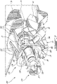
Fig. 7 is a schematic tridimensional view of an engine assembly and mount assembly in accordance with another particular embodiment; -
Fig. 8 is a schematic front view of the assemblies ofFig. 7 ; and -
Fig. 9 is a schematic cross-sectional view of the assemblies ofFig. 7 . - Referring to
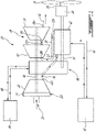
Fig. 1 , anengine assembly 10 is generally shown and includes aninternal combustion engine 12. In a particular embodiment, theengine assembly 10 is a compound cycle engine system or compound cycle engine such as described inLents et al.'s US patent No. 7,753,036 issued July 13, 2010 or as described inJulien et al.'s US patent No. 7,775,044 issued August 17, 2010 , or as described inThomassin et al.'s U.S. patent publication No. 2015/0275749 published October 1, 2015 , or as described inBolduc et al.'s U.S. patent publication No. 2015/0275756 published October 1, 2015 . The engine assembly may be used as a prime mover engine on an aircraft. - In the embodiment shown, the
internal combustion engine 12 is an intermittent internal combustion engine including one or more rotor assembly(ies), for example three rotor assemblies, each configured for example as a Wankel engine; it is understood that theinternal combustion engine 12 may have any other suitable configuration, for example including one or more reciprocating pistons. Theinternal combustion engine 12 drives anengine shaft 14 that is drivingly engaged to apropeller shaft 16 via areduction gearbox 18 so as to drive anaircraft propeller 20. It is however understood that theengine assembly 10 may additionally be configured to drive any other appropriate type of load, including, but not limited to, one or more generator(s), accessory(ies), rotor mast(s), compressor(s), or any other appropriate type of load or combination thereof. - The
engine assembly 10 also includes acompressor 22 for compressing the air before it is fed to anintake 12i of theinternal combustion engine 12. Theengine intake 12i may for example correspond to or communicate with the inlet port of each rotor assembly or reciprocating piston of theinternal combustion engine 12. An inlet plenum orscroll 24 is fluidly connected to a source of air, for example an environment of the aircraft, via asuitable inlet conduit 25, and is in fluid communication with aninlet 22i of thecompressor 22. An outlet 22o of thecompressor 22 is in fluid communication with theair intake 12i of theinternal combustion engine 12, for example via asuitable conduit 26. - The
engine assembly 10 further includes aturbine section 28 receiving the exhaust gases from theinternal combustion engine 12, for example an exhaust flow of high pressure hot gas exiting at high peak velocity in the form of exhaust pulses. In the illustrated embodiment, an exhaust 12o of theinternal combustion engine 12 is in fluid communication with aninlet 28i of theturbine section 28 via asuitable conduit 30. The exhaust 12o of theinternal combustion engine 12 may for example correspond to or communicate with the exhaust port of each rotor assembly or reciprocating piston of theinternal combustion engine 12. In the embodiment shown, theturbine section 28 comprises twoturbine stages first turbine stage 32 defines theinlet 28i of theturbine section 28 communicating with the exhaust 12o of theinternal combustion engine 12, and an outlet 32o of thefirst turbine stage 32 communicates with aninlet 34i of thesecond turbine stage 34. Other configurations are contemplated. The flow of exhaust gases exits an outlet 28o of the turbine section 28 (e.g. an outlet of the second turbine stage 34), for example via anexhaust conduit 36 connected to the outlet 28o of theturbine section 28 and in fluid communication with the environment of the aircraft (i.e. with atmosphere). - In the embodiment shown, the
engine shaft 14, thecompressor 22 and theturbine section 28 are in driving engagement with each other via acompounding gearbox 38. Thegearbox 38 is configured to allow theturbine section 28 to compound power with theengine shaft 14 and to allow theturbine section 28 and/or theinternal combustion engine 12 to drive thecompressor 22. Thegearbox 38 may also be drivingly engaged to engine accessories (not shown). In the embodiment shown, theturbine section 28 includes aturbine shaft 40, to which the rotors of theturbine section 28 are connected. Theturbine shaft 40 extends through thegearbox 38 and also receives the rotor(s) of thecompressor 22. Theturbine shaft 40 is drivingly engaged to theengine shaft 14 via thegearbox 38. Accordingly, the power from theturbine shaft 40 andengine shaft 14 is compounded by thegearbox 38 to drive thepropeller 20 and thecompressor 22. It is understood that any other suitable manner of compounding power from theturbine shaft 40 with power from theengine shaft 14 mal alternately be used, including, but not limited to, a driving engagement between theturbine shaft 40 and theengine shaft 14 via the reduction gearbox 18 (see e.g.Figs. 7-9 discussed further below), electrical compounding via power transfer between generators connected to the independently rotatable shafts, etc. In the embodiment shown, theturbine shaft 40 andengine shaft 14 are parallel to and offset from each other. Other configurations are also possible. - The
engine assembly 10 also includes afirst heat exchanger 42 configured as a coolant cooler. Theheat exchanger 42 has one or more coolant conduits fluidly connected to acoolant circulation system 44, which is fluidly connected to theinternal combustion engine 12 to circulate a cooling fluid therein. Accordingly, theheat exchanger 42 is configured to receive and cool the cooling fluid circulated out of theinternal combustion engine 12 before the cooling fluid is circulated back to theinternal combustion engine 12. Theheat exchanger 42 further includes one or more air conduits configured for circulation of cooling air therethrough, with the air conduit(s) and coolant conduit(s) being in heat exchange relationship with each other so that circulation of cooling air through the cooling conduit(s) provides cooling of the cooling fluid circulating through the coolant conduit(s). The cooling fluid may be a suitable liquid coolant, for example a suitable water-based coolant. Although not shown, it is understood that thecoolant circulation system 44 includes one or more pump(s) or any other suitable mechanism for driving the circulation of the cooling fluid through thecoolant circulation system 44, including between theinternal combustion engine 12 and theheat exchanger 42. - The
engine assembly 10 further includes asecond heat exchanger 46 configured as a lubricant cooler. Thesecond heat exchanger 46 has one or more lubricant conduits fluidly connected to alubricant circulation system 48 of theengine assembly 10. Thelubricant circulation system 48 is fluidly connected to one or more components of theengine assembly 10 to circulate a lubricant thereto; in the embodiment shown, thelubricant circulation system 48 is connected to thegearbox 38, and thegearbox 38 includes a casing which may also contain bearings supporting theshafts second heat exchanger 46 is configured to receive and cool the lubricant before the lubricant is circulated back to the component(s) of theengine assembly 10. Thesecond heat exchanger 46 further includes one or more air conduits configured for circulation of cooling air therethrough, with the air conduit(s) and lubricant conduit(s) being in heat exchange relationship with each other so that circulation of cooling air through the cooling conduit(s) provides cooling of the lubricant circulating through the lubricant conduit(s). The lubricant may be a suitable liquid lubricant, for example a suitable type of oil. Although not shown, it is understood that thelubricant circulation system 48 includes one or more pump(s) or any other suitable mechanism for driving the circulation of the lubrication through thelubricant circulation system 48, including between the component(s) of theengine assembly 10 and thesecond heat exchanger 46. - Although each
heat exchanger respective circulation system heat exchanger lubricant circulation systems - Referring to
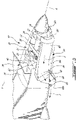
Figs. 2-6 , anassembly 50 configured as a nose assembly for a front end of an aircraft and including theengine assembly 10 is generally shown. Referring particularly toFigs. 2-3 , thenose assembly 50 is received in a front ornose nacelle 52 of the aircraft: thereduction gearbox 18 is connected to the front of the internal combustion engine 12 (as shown, including three rotor assemblies each configured as a Wankel engine), thecompounding gearbox 38 is connected to the rear of theinternal combustion engine 12, theturbine section 28 is connected to thecompounding gearbox 38 and extends side-by-side with theinternal combustion engine 12, and thecompressor 22 is located aft of theturbine section 28. Other configurations are also possible. - The
assembly 50 includes a wheel well 54 located under theengine assembly 10, and configured for receiving a retractable landing gear 56 (seeFig. 4 ) when in a retracted configuration. Thewheel well 54 has a plurality of interconnected walls which form a box for containing thelanding gear 56 when retracted:side walls 54s, a front wall and a rear wall together defining a perimeter which in the embodiment shown is rectangular, and atop wall 54t (Fig. 2 ) connected to the side, front and rear walls so as to close the top of the box. Thewheel well 54 has a selectively closable bottom opening opposed to thetop wall 54t, for deploying theretractable landing gear 56 therethrough. In the embodiment shown, a pivotable door 58 (seeFigs. 5-6 ) selectively closes the bottom opening of the wheel well 54, with thedoor 58 being pivotally connected to the aircraft (e.g. to one of the side, front and rear walls of the wheel well 54). Other configurations are possible. - Still referring to
Figs. 2-3 , theassembly 50 further includes cooling ducts feeding cooling air to theheat exchangers 42, 46: the first, e.g. coolant,heat exchanger 42 is positioned and configured for receiving a cooling airflow from thefirst cooling duct 60, and the second, e.g. lubricant,heat exchanger 46 is positioned and configured for receiving a cooling airflow from thesecond cooling duct 62. In the embodiment shown, thefirst heat exchanger 42 is received in thefirst cooling duct 60 and thesecond heat exchanger 46 is received in thesecond cooling duct 62. Eachheat exchanger respective cooling duct duct heat exchanger ducts wheel well 54 is located between theheat exchangers Fig. 2 . In the embodiment shown, theinternal combustion engine 12,compressor 22 andturbine section 28 are all located between the twocooling ducts heat exchangers cooling ducts heat exchangers heat exchangers internal combustion engine 12,compressor 22, andturbine section 28. - The cooling
ducts front inlet duct inlets Fig. 2 ) so as to benefit from the pressure increase in the air created by thepropeller 20. Thereduction gearbox 18 is thus located adjacent to and between the coolingduct inlets Fig. 5 , the coolingducts wheel well 54 is located between the two outlets 60o, 62o. - Referring back to
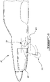
Fig. 3 , each coolingduct portion 64 and anozzle portion 66. Therespective heat exchanger portion 64 and upstream of thenozzle portion 66, e.g. the diffusingportion 64 extends immediately upstream from theheat exchanger nozzle portion 66 extends immediately downstream from theheat exchanger portion 64 has a progressively increasing cross-sectional area along the direction of flow F within the coolingduct nozzle portion 66 has a progressively reducing cross-sectional area along the direction of flow F. Each coolingduct heat exchanger heat exchanger 42, 46 (e.g., from Mach 0.35 at the coolingduct inlet heat exchanger 42, 46), and a cross-sectional area which reduces after theheat exchanger - As can also be best seen in
Fig. 3 , each coolingduct duct inlet portion 64, so that the flow in the coolingduct portion 64 then turns the flow downwardly, so that the cooling airflow through theheat exchanger nozzle portion 66 downstream thereof is performed at a non-zero angle with respect to the longitudinal direction (roll axis R) and with respect to the normal direction (yaw axis Y). - As can be best seen in
Figs. 5-6 , the downstream end 68 of each of thecooling ducts nozzle portion 66 and defines the cooling duct outlet 60o, 62o, protrudes downwardly from thenacelle 52 receiving theengine assembly 10. The downstream ends 68 of thecooling ducts duct Fig. 3 ). The downstream ends 68 are thus oriented so that the flow F out of the cooling duct outlets 60o 62o is directed rearwardly and longitudinally, underneath thenacelle 52. In a particular embodiment, thenozzle portions 66, downstream ends 68 and cooling duct outlets 60o, 62o enable ram recovery of the cooling airstream so as to reduce or minimize the drag induced by the extraction of the cooling airflows. - As can be best seen in
Figs. 5-6 , theinlet conduit 25 for thecompressor 22 has aninlet 25i located between theinlets cooling ducts inlet conduit 25 defines the fluid communication between the environment of the aircraft and theinlet 22i of thecompressor 22 independently of and separately from the coolingducts exhaust conduit 36 for theturbine section 28 has an outlet 36o located forward of the outlet 62o of one of thecooling ducts 62. Theexhaust conduit 36 defines the fluid communication between the outlet 28o of theturbine section 28 and the environment of the aircraft independently of and separately from the coolingducts - As can be best seen in
Fig. 2 , in the embodiment shown thecooling ducts cooling ducts heat exchangers heat exchanger 46 received in the smallest cooling duct 62 (e.g. lubricant heat exchanger) has a lower cooling airflow requirement than the other heat exchanger 42 (e.g. liquid coolant heat exchanger). - In another embodiment, the
inlet conduit 25 for thecompressor 22 and/or theexhaust conduit 36 for theturbine section 28 may be combined with or communicate with the coolingduct 62 containing theheat exchanger 46 requiring the lowest cooling air flow; this may enable to have two cooling ducts of similar or equal cross-sectional areas with respect to each other, for example cooling ducts symmetrical about the longitudinal axis R of the aircraft, despite one of theheat exchanger 46 requiring a smaller cooling airflow than theother heat exchanger 42. - In another embodiment, cooling for both the liquid coolant and the lubricant is provided in one or both of the
cooling ducts - Still referring to
Fig. 2 , in the embodiment shown theengine assembly 10 is located over the wheel well 54, and mounted thereto. The walls of the wheel well 54 define a structural assembly, sized so as to be able to support the loads generated by theengine assembly 10. Amount assembly 70 thus interconnects theengine assembly 10 to one or more of the walls of the wheel well 54, for example to thetop wall 54t (as shown) or theside walls 54s. - In the embodiment shown, the
mount assembly 70 is connected to theengine assembly 10 by being connected to the casing of the compoundinggearbox 38, for example to a bottom wall of the casing. Themount assembly 70 includes twostruts 72 connected to thegearbox 38 in an adjacent manner, for example by being connected to a same mount attached to thegearbox 38. Thestruts 72 extend at an angle with respect to each other. Thestruts 72 are connected to thetop wall 54t of the wheel well 54 at spaced apart locations (as shown), or are each connected to one of theside walls 54s of thewheel well 54. Other configurations are also possible. Although not shown, more than one mount (for example, two engine mounts) may be provided on thegearbox 38. - In the embodiment shown, the
mount assembly 70 also includes two struts interconnecting the engine assembly 10 (e.g. a top wall of the casing of the compounding gearbox 38) to the aircraft structure, for example to asupport 74 engaged to an aft bulkhead/firewall 76 of thenacelle 52. - Referring to
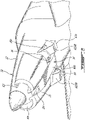
Figs. 7-9 , anose assembly 150 for a front end of an aircraft and including anengine assembly 110 and amount assembly 170 in accordance with another embodiment is shown, where elements similar to that of the previous embodiments are identified by the same reference numerals and will not be further described herein. Some elements, such as the cooling ducts, are omitted for improved clarity. - In this embodiment, the
gearbox 138 at the rear of theinternal combustion engine 12 is an accessory gearbox, and is engaged to the engine shaft without being engaged to the turbine shaft; it is also engaged to one or more accessories to allow the engine shaft to drive the accessory(ies) via thegearbox 138. Thereduction gearbox 118 at the front of the internal combustion engine also acts as a compounding gearbox, and drivingly engages the engine shaft and the turbine shaft with each other, as well as with thepropeller shaft 16. - In this embodiment, the
mount assembly 170 includes anupper yoke 178 and alower yoke 180 which cooperate to surround the engine, and which are both connected to the aircraft structure, for example the nacelle skin. In the embodiment shown, theupper yoke 178 is fixed and thelower yoke 180 is removable for installation and removal of theengine assembly 110. Theupper yoke 178 andlower yoke 180 are each connected to theaccessory gearbox 138 via one or more engine mounts 182; the engine mounts 182 extend radially from the casing of theaccessory gearbox 138, and each include an isolator having a central opening configured for receiving an axially extending bolt interconnecting the isolator to thecorresponding yoke upper yoke 178 is connected to the casing of thegearbox 138 by asingle mount 182 while thelower yoke 180 is connected to the casing of thegearbox 138 via two mounts 182. Other configurations are possible, including, but not limited to, a configuration where twomounts 182 peryoke - As can be best seen in
Fig. 7 , theupper yoke 178 is connected to asupport 74 forming part of or connected to the aircraft structure via a plurality ofupper struts 184. In the embodiment shown, six (6)upper struts 184 are provided forming a "zig-zag" pattern between theupper yoke 178 and the support 74: theupper struts 184 are connected to theupper yoke 178 in pairs of struts extending at an angle from each other, and the four central ones of theupper struts 184 are connected to thesupport 74 in different pairs of struts extending at an angle from each other. Other configurations are also possible. - In the embodiment shown and as can be best seen in
Fig. 9 , thesupport 74 extends upwardly spaced apart from thetop wall 54t of thewheel well 54. However, theside walls 54s of the wheel well 54 extend upwardly beyond thetop wall 54t so that thesupport 74 rests on the top edges of theside walls 54s. The loads of thesupport 74 are accordingly shared between the aircraft structure and the structure (walls) of thewheel well 54. - As can be best seen in
Fig. 8 , thelower yoke 180 is connected to the walls of the wheel well 54 via a plurality oflower struts 186. In the embodiment shown, two (2)lower struts 186 are provided, each extending between thelower yoke 178 and a respective one of theside walls 54s. Other configurations, including, but not limited to, a greater number of struts interconnecting thelower yoke 180 and the walls of the wheel well 54, are also possible. - It is understood that the
engine assembly 10 ofFigs. 1-6 may be used with themount assembly 170 ofFigs. 7-9 and that theengine assembly 110 ofFigs. 7-9 may be used with themount assembly 70 ofFigs. 2-3 . - Although the
assemblies engine assembly 10 ofFig. 1 or thesimilar engine assembly 110, it is understood that any other suitable type of engine assembly may alternately be used. For example, thecompressor 22 and/orturbine section 28 may be omitted; theturbine section 28 may be present but independent from theinternal combustion engine 12, i.e. the power compounding between theinternal combustion engine 12 andturbine section 28 may be omitted; etc. - Moreover, it is understood that although the
assemblies assemblies - In use and in accordance with a particular embodiment, the lubricant and liquid coolant of the
engine assembly duct cooling ducts 60 with the associated cooling airflow, and at least the lubricant in the other coolingduct 62 with the associated cooling airflow. The cooling airflows are circulated through theheat exchangers cooling ducts engine assembly heat exchangers 42, 46 (e.g., via the cooling fluid and/or lubricant). The cooling airflows are circulated out of thecooling ducts wheel well 54. - In use and in accordance with a particular embodiment, the
engine assembly engine assembly engine assembly 10 to at least onewall 54t of thewheel well 54.
Claims (14)
- An assembly (50; 150) for an aircraft having a propeller (20), the assembly (50; 150) comprising:a wheel well (54) configured for receiving a retracted landing gear (56), the wheel well (54) including walls and a closable bottom opening for deploying the landing gear (56) therethrough;an engine assembly (10; 110) having an engine shaft (14) configured for driving engagement with a propeller (20); anda mount assembly (70; 170) for supporting the engine assembly (10; 110), the mount assembly (70; 170) connected to at least one of the walls of the wheel well (54).
- The assembly (50; 150) as defined in claim 1, wherein the engine assembly (10; 110) includes a gearbox (38; 138) in driving engagement with the engine shaft (14), the mount assembly (70; 170) connected to a casing of the gearbox (38; 138).
- The assembly (50; 150) as defined in claim 2, wherein the engine assembly (10; 110) includes an intermittent internal combustion engine (12) drivingly engaged to the engine shaft (14) and a turbine (28) having an inlet (28i) in fluid communication with an exhaust (12o) of the intermittent internal combustion engine (12), the turbine (28) having a turbine shaft (40) in driving engagement with the engine shaft (14) via the gearbox (38; 138).
- The assembly (50; 150) as defined in claim 1, 2 or 3, wherein the engine assembly (10; 110) includes at least one Wankel rotary engine drivingly engaged to the engine shaft (14).
- The assembly (50; 150) as defined in claim 1, wherein the engine assembly (10; 110) includes a rotary internal combustion engine (12) in driving engagement with the engine shaft (14), and a gearbox drivingly engaged to the engine shaft (14), the mount assembly (70; 170) interconnecting a casing of the gearbox (38; 138) to at least one of the walls of the wheel well (54).
- The assembly (50; 150) as defined in claim 5, wherein the engine assembly (10; 110) includes a turbine (28) having an inlet (28i) in fluid communication with an exhaust (12o) of the rotary internal combustion engine (12), the turbine (28) having a turbine shaft (40) in driving engagement with the engine shaft (14) via the gearbox (38; 138).
- The assembly (50; 150) as defined in any preceding claim, wherein the assembly (50; 150) is a nose assembly for a front end of the aircraft, the propeller (20) is a nose propeller, and the landing gear (56) is a nose landing gear.
- The assembly (50; 150) as defined in any preceding claim, wherein the walls of the wheel well (54) include side walls (54s), the mount assembly (70; 170) connected to the side walls (54s).
- The assembly (150) as defined in any preceding claim, wherein the mount assembly (170) includes upper and lower yokes (178, 180) connected to the engine assembly (110) or the casing of the gearbox (138), the lower yoke (180) connected to the at least one of the walls of the wheel well (54).
- The assembly (150) as defined in claim 9, wherein the upper yoke (178) is configured to be connected to a structure of the aircraft.
- The assembly (150) as defined in claim 10, wherein the walls of the wheel well (54) include a top wall (54t) and side walls (54s) extending upwardly beyond the top wall (54t), the upper yoke (178) connected to a support (74) upwardly spaced apart from the top wall (54t) and resting on top edges of the side walls (54s), the support (74) configured to be connected to a structure of the aircraft.
- The assembly (150) as defined in any preceding claim, wherein the mount assembly (170) includes a plurality of upper struts (184) configured to be connected to a structure of the aircraft and a plurality of lower struts (186) connected to the at least one wall of the wheel well (54), the upper and lower struts (184, 186) connected to the engine assembly (110) or the casing of the gearbox (138).
- The assembly (50; 150) as defined in any preceding claim, wherein the wheel well (54) is located under the engine assembly (10; 110).
- A method of supporting an engine assembly (10; 110) in an aircraft having a retractable landing gear (56) and a propeller (20) driven by the engine assembly (10; 110), the method comprising:locating the engine assembly (10; 110) above and spaced from a wheel well (54) configured for receiving the retractable landing gear (56) in a retracted configuration; andmechanically interconnecting the engine assembly (10; 110) to at least one wall of the wheel well (54) via a mount assembly (70; 170) supporting the engine assembly (10; 110).
Applications Claiming Priority (1)
| Application Number | Priority Date | Filing Date | Title |
|---|---|---|---|
| US15/898,741 US10870493B2 (en) | 2018-02-19 | 2018-02-19 | Aircraft with engine assembly mounted to wheel well |
Publications (2)
| Publication Number | Publication Date |
|---|---|
| EP3527490A1 EP3527490A1 (en) | 2019-08-21 |
| EP3527490B1 true EP3527490B1 (en) | 2022-04-06 |
Family
ID=65529306
Family Applications (1)
| Application Number | Title | Priority Date | Filing Date |
|---|---|---|---|
| EP19158136.2A Active EP3527490B1 (en) | 2018-02-19 | 2019-02-19 | Aircraft with engine assembly mounted to wheel well |
Country Status (4)
| Country | Link |
|---|---|
| US (1) | US10870493B2 (en) |
| EP (1) | EP3527490B1 (en) |
| CA (1) | CA3033874A1 (en) |
| PL (1) | PL3527490T3 (en) |
Families Citing this family (2)
| Publication number | Priority date | Publication date | Assignee | Title |
|---|---|---|---|---|
| US10858115B2 (en) * | 2018-02-19 | 2020-12-08 | Pratt & Whitney Canada Corp. | Aircraft with wheel well between heat exchangers of engine assembly |
| US11628942B2 (en) * | 2019-03-01 | 2023-04-18 | Pratt & Whitney Canada Corp. | Torque ripple control for an aircraft power train |
Family Cites Families (33)
| Publication number | Priority date | Publication date | Assignee | Title |
|---|---|---|---|---|
| US1427872A (en) | 1919-08-23 | 1922-09-05 | Alfred V Verville | Airplane-radiator mounting |
| US1839563A (en) * | 1931-01-26 | 1932-01-05 | Klingaman Herman | Aircraft |
| US1934992A (en) * | 1933-03-13 | 1933-11-14 | Gen Aviat Mfg Corp | Retractable landing gear |
| US2025743A (en) * | 1933-03-20 | 1935-12-31 | Curtiss Aeroplane & Motor Co | Retractable landing gear |
| US2087832A (en) | 1935-12-24 | 1937-07-20 | Birkigt Maro | Motive power plant |
| GB493673A (en) | 1936-12-22 | 1938-10-12 | Messerschmitt Boelkow Blohm | Improvements in and relating to radiators for the engines of aircraft or other vehicles |
| US2219980A (en) | 1938-06-15 | 1940-10-29 | Seversky Aireraft Corp | Aircraft |
| US2214723A (en) | 1938-08-25 | 1940-09-10 | Curtiss Wright Corp | Windshield air scoop |
| US2338046A (en) * | 1939-06-10 | 1943-12-28 | Armstrong Whitworth Co Eng | Landing gear of airplanes |
| US2340396A (en) | 1940-05-11 | 1944-02-01 | Mcdonnell Aircraft Corp | Airplane power plant cooling |
| US2388247A (en) | 1940-11-22 | 1945-11-06 | Central Aircraft Corp | Airplane |
| US2372250A (en) | 1941-06-27 | 1945-03-27 | V J Burnelli Airplanes Inc | Combined engine cooling and jet propulsion means |
| DE853388C (en) | 1941-08-05 | 1952-10-23 | Daimler Benz Ag | Cooling device arranged within the aircraft fuselage or the engine nacelle in front of the drive engine |
| US2477637A (en) | 1941-11-14 | 1949-08-02 | Mercier Pierre Ernest | Aircraft |
| US2540991A (en) | 1942-03-06 | 1951-02-06 | Lockheed Aircraft Corp | Gas reaction aircraft power plant |
| US2504137A (en) | 1942-08-24 | 1950-04-18 | William L Lewis | Airplane propulsion and stabilizing device |
| GB571741A (en) | 1944-03-02 | 1945-09-06 | Bristol Aeroplane Co Ltd | Improvements in or relating to supercharged internal combustion engines |
| US2410856A (en) | 1944-07-15 | 1946-11-12 | Otto C Koppen | Airplane |
| US2434085A (en) | 1945-04-13 | 1948-01-06 | Cons Vultee Aircraft Corp | Oil temperature controlling apparatus for pusher type airplanes |
| US2605851A (en) | 1946-11-30 | 1952-08-05 | Chrysler Corp | Air intake for aircraft turbopropeller power plant |
| US2815184A (en) * | 1954-04-02 | 1957-12-03 | Northrop Aircraft Inc | Aircraft engine hoist and mounting system |
| US2988065A (en) * | 1958-03-11 | 1961-06-13 | Nsu Motorenwerke Ag | Rotary internal combustion engine |
| US3028124A (en) * | 1958-05-16 | 1962-04-03 | Napier & Son Ltd | Mounting system of aircraft power plants |
| US4408736A (en) * | 1981-03-23 | 1983-10-11 | Grumman Aerospace Corporation | Landing gear door mud guard |
| US4456458A (en) | 1982-09-20 | 1984-06-26 | The De Havilland Aircraft Of Canada, Limited | Air intake system for engine |
| US4829850A (en) | 1987-02-25 | 1989-05-16 | Soloy Dual Pac, Inc. | Multiple engine drive for single output shaft and combining gearbox therefor |
| US5435502A (en) | 1993-01-25 | 1995-07-25 | Wernicke; Kenneth G. | Flying and road vehicle |
| WO2004074655A1 (en) | 2003-02-24 | 2004-09-02 | Pratt & Whitney Canada Corp. | Low volumetric compression ratio integrated turbo-compound rotary engine |
| US7753036B2 (en) | 2007-07-02 | 2010-07-13 | United Technologies Corporation | Compound cycle rotary engine |
| US10107195B2 (en) | 2012-07-20 | 2018-10-23 | Pratt & Whitney Canada Corp. | Compound cycle engine |
| US9926843B2 (en) | 2012-07-20 | 2018-03-27 | Pratt & Whitney Canada Corp. | Compound cycle engine |
| FR3018503B1 (en) | 2014-03-13 | 2017-10-13 | Snecma | NACELLE COMPRISING AN EXCHANGER FOR COOLING A FLOW OF AIR |
| US10533500B2 (en) | 2015-02-20 | 2020-01-14 | Pratt & Whitney Canada Corp. | Compound engine assembly with mount cage |
-
2018
- 2018-02-19 US US15/898,741 patent/US10870493B2/en active Active
-
2019
- 2019-02-12 CA CA3033874A patent/CA3033874A1/en active Pending
- 2019-02-19 EP EP19158136.2A patent/EP3527490B1/en active Active
- 2019-02-19 PL PL19158136.2T patent/PL3527490T3/en unknown
Non-Patent Citations (1)
| Title |
|---|
| None * |
Also Published As
| Publication number | Publication date |
|---|---|
| EP3527490A1 (en) | 2019-08-21 |
| CA3033874A1 (en) | 2019-08-19 |
| US10870493B2 (en) | 2020-12-22 |
| US20190256214A1 (en) | 2019-08-22 |
| PL3527490T3 (en) | 2022-08-16 |
Similar Documents
| Publication | Publication Date | Title |
|---|---|---|
| EP3500748B1 (en) | Propulsion engine for aircraft | |
| EP3064743B1 (en) | Aircraft compound engine assembly with cantilevered compressor and turbine and a corresponding method | |
| US20180050811A1 (en) | Propulsion engine for an aircraft | |
| EP2383441B1 (en) | A gas turbine engine | |
| EP3059420B1 (en) | Compound engine assembly with inlet lip anti-icing | |
| US20200141370A1 (en) | Engine assembly with engine and cooler compartments | |
| EP2578843A2 (en) | Combined pump system for size reduction of thermal management heat exchangers and optimized ventilation to the aircraft cabin | |
| CA2921396C (en) | Engine assembly with modular compressor and turbine | |
| EP3059416B1 (en) | Compound engine assembly with offset turbine shaft, engine shaft and inlet duct and corresponding method | |
| EP3527490B1 (en) | Aircraft with engine assembly mounted to wheel well | |
| EP3527496B1 (en) | Aircraft with wheel well between heat exchangers of engine assembly | |
| EP3527497B1 (en) | Aircraft with wheel well between cooling duct outlets | |
| US20150361891A1 (en) | Air-Oil Heat Exchangers with Minimum Bypass Flow Pressure Loss | |
| CN112046768A (en) | Aircraft power plant | |
| US20100326049A1 (en) | Cooling systems for rotorcraft engines | |
| US10823041B2 (en) | Engine assembly with plenum and remote fan | |
| EP3702284B1 (en) | Aircraft system | |
| CN114348277A (en) | Aircraft propulsion system with propeller and cooling fan | |
| RU2022886C1 (en) | Power plant |
Legal Events
| Date | Code | Title | Description |
|---|---|---|---|
| PUAI | Public reference made under article 153(3) epc to a published international application that has entered the european phase |
Free format text: ORIGINAL CODE: 0009012 |
|
| STAA | Information on the status of an ep patent application or granted ep patent |
Free format text: STATUS: THE APPLICATION HAS BEEN PUBLISHED |
|
| AK | Designated contracting states |
Kind code of ref document: A1 Designated state(s): AL AT BE BG CH CY CZ DE DK EE ES FI FR GB GR HR HU IE IS IT LI LT LU LV MC MK MT NL NO PL PT RO RS SE SI SK SM TR |
|
| AX | Request for extension of the european patent |
Extension state: BA ME |
|
| STAA | Information on the status of an ep patent application or granted ep patent |
Free format text: STATUS: REQUEST FOR EXAMINATION WAS MADE |
|
| 17P | Request for examination filed |
Effective date: 20200221 |
|
| RBV | Designated contracting states (corrected) |
Designated state(s): AL AT BE BG CH CY CZ DE DK EE ES FI FR GB GR HR HU IE IS IT LI LT LU LV MC MK MT NL NO PL PT RO RS SE SI SK SM TR |
|
| STAA | Information on the status of an ep patent application or granted ep patent |
Free format text: STATUS: EXAMINATION IS IN PROGRESS |
|
| STAA | Information on the status of an ep patent application or granted ep patent |
Free format text: STATUS: EXAMINATION IS IN PROGRESS |
|
| 17Q | First examination report despatched |
Effective date: 20201120 |
|
| GRAP | Despatch of communication of intention to grant a patent |
Free format text: ORIGINAL CODE: EPIDOSNIGR1 |
|
| STAA | Information on the status of an ep patent application or granted ep patent |
Free format text: STATUS: GRANT OF PATENT IS INTENDED |
|
| INTG | Intention to grant announced |
Effective date: 20211019 |
|
| GRAS | Grant fee paid |
Free format text: ORIGINAL CODE: EPIDOSNIGR3 |
|
| GRAA | (expected) grant |
Free format text: ORIGINAL CODE: 0009210 |
|
| STAA | Information on the status of an ep patent application or granted ep patent |
Free format text: STATUS: THE PATENT HAS BEEN GRANTED |
|
| AK | Designated contracting states |
Kind code of ref document: B1 Designated state(s): AL AT BE BG CH CY CZ DE DK EE ES FI FR GB GR HR HU IE IS IT LI LT LU LV MC MK MT NL NO PL PT RO RS SE SI SK SM TR |
|
| REG | Reference to a national code |
Ref country code: GB Ref legal event code: FG4D |
|
| REG | Reference to a national code |
Ref country code: CH Ref legal event code: EP |
|
| REG | Reference to a national code |
Ref country code: AT Ref legal event code: REF Ref document number: 1481111 Country of ref document: AT Kind code of ref document: T Effective date: 20220415 |
|
| REG | Reference to a national code |
Ref country code: DE Ref legal event code: R096 Ref document number: 602019013244 Country of ref document: DE |
|
| REG | Reference to a national code |
Ref country code: IE Ref legal event code: FG4D |
|
| REG | Reference to a national code |
Ref country code: LT Ref legal event code: MG9D |
|
| REG | Reference to a national code |
Ref country code: NL Ref legal event code: MP Effective date: 20220406 |
|
| REG | Reference to a national code |
Ref country code: AT Ref legal event code: MK05 Ref document number: 1481111 Country of ref document: AT Kind code of ref document: T Effective date: 20220406 |
|
| PG25 | Lapsed in a contracting state [announced via postgrant information from national office to epo] |
Ref country code: NL Free format text: LAPSE BECAUSE OF FAILURE TO SUBMIT A TRANSLATION OF THE DESCRIPTION OR TO PAY THE FEE WITHIN THE PRESCRIBED TIME-LIMIT Effective date: 20220406 |
|
| PG25 | Lapsed in a contracting state [announced via postgrant information from national office to epo] |
Ref country code: SE Free format text: LAPSE BECAUSE OF FAILURE TO SUBMIT A TRANSLATION OF THE DESCRIPTION OR TO PAY THE FEE WITHIN THE PRESCRIBED TIME-LIMIT Effective date: 20220406 Ref country code: PT Free format text: LAPSE BECAUSE OF FAILURE TO SUBMIT A TRANSLATION OF THE DESCRIPTION OR TO PAY THE FEE WITHIN THE PRESCRIBED TIME-LIMIT Effective date: 20220808 Ref country code: NO Free format text: LAPSE BECAUSE OF FAILURE TO SUBMIT A TRANSLATION OF THE DESCRIPTION OR TO PAY THE FEE WITHIN THE PRESCRIBED TIME-LIMIT Effective date: 20220706 Ref country code: LT Free format text: LAPSE BECAUSE OF FAILURE TO SUBMIT A TRANSLATION OF THE DESCRIPTION OR TO PAY THE FEE WITHIN THE PRESCRIBED TIME-LIMIT Effective date: 20220406 Ref country code: HR Free format text: LAPSE BECAUSE OF FAILURE TO SUBMIT A TRANSLATION OF THE DESCRIPTION OR TO PAY THE FEE WITHIN THE PRESCRIBED TIME-LIMIT Effective date: 20220406 Ref country code: GR Free format text: LAPSE BECAUSE OF FAILURE TO SUBMIT A TRANSLATION OF THE DESCRIPTION OR TO PAY THE FEE WITHIN THE PRESCRIBED TIME-LIMIT Effective date: 20220707 Ref country code: FI Free format text: LAPSE BECAUSE OF FAILURE TO SUBMIT A TRANSLATION OF THE DESCRIPTION OR TO PAY THE FEE WITHIN THE PRESCRIBED TIME-LIMIT Effective date: 20220406 Ref country code: ES Free format text: LAPSE BECAUSE OF FAILURE TO SUBMIT A TRANSLATION OF THE DESCRIPTION OR TO PAY THE FEE WITHIN THE PRESCRIBED TIME-LIMIT Effective date: 20220406 Ref country code: BG Free format text: LAPSE BECAUSE OF FAILURE TO SUBMIT A TRANSLATION OF THE DESCRIPTION OR TO PAY THE FEE WITHIN THE PRESCRIBED TIME-LIMIT Effective date: 20220706 Ref country code: AT Free format text: LAPSE BECAUSE OF FAILURE TO SUBMIT A TRANSLATION OF THE DESCRIPTION OR TO PAY THE FEE WITHIN THE PRESCRIBED TIME-LIMIT Effective date: 20220406 |
|
| PG25 | Lapsed in a contracting state [announced via postgrant information from national office to epo] |
Ref country code: RS Free format text: LAPSE BECAUSE OF FAILURE TO SUBMIT A TRANSLATION OF THE DESCRIPTION OR TO PAY THE FEE WITHIN THE PRESCRIBED TIME-LIMIT Effective date: 20220406 Ref country code: LV Free format text: LAPSE BECAUSE OF FAILURE TO SUBMIT A TRANSLATION OF THE DESCRIPTION OR TO PAY THE FEE WITHIN THE PRESCRIBED TIME-LIMIT Effective date: 20220406 Ref country code: IS Free format text: LAPSE BECAUSE OF FAILURE TO SUBMIT A TRANSLATION OF THE DESCRIPTION OR TO PAY THE FEE WITHIN THE PRESCRIBED TIME-LIMIT Effective date: 20220806 |
|
| REG | Reference to a national code |
Ref country code: DE Ref legal event code: R097 Ref document number: 602019013244 Country of ref document: DE |
|
| PG25 | Lapsed in a contracting state [announced via postgrant information from national office to epo] |
Ref country code: SM Free format text: LAPSE BECAUSE OF FAILURE TO SUBMIT A TRANSLATION OF THE DESCRIPTION OR TO PAY THE FEE WITHIN THE PRESCRIBED TIME-LIMIT Effective date: 20220406 Ref country code: SK Free format text: LAPSE BECAUSE OF FAILURE TO SUBMIT A TRANSLATION OF THE DESCRIPTION OR TO PAY THE FEE WITHIN THE PRESCRIBED TIME-LIMIT Effective date: 20220406 Ref country code: RO Free format text: LAPSE BECAUSE OF FAILURE TO SUBMIT A TRANSLATION OF THE DESCRIPTION OR TO PAY THE FEE WITHIN THE PRESCRIBED TIME-LIMIT Effective date: 20220406 Ref country code: EE Free format text: LAPSE BECAUSE OF FAILURE TO SUBMIT A TRANSLATION OF THE DESCRIPTION OR TO PAY THE FEE WITHIN THE PRESCRIBED TIME-LIMIT Effective date: 20220406 Ref country code: DK Free format text: LAPSE BECAUSE OF FAILURE TO SUBMIT A TRANSLATION OF THE DESCRIPTION OR TO PAY THE FEE WITHIN THE PRESCRIBED TIME-LIMIT Effective date: 20220406 |
|
| PLBE | No opposition filed within time limit |
Free format text: ORIGINAL CODE: 0009261 |
|
| STAA | Information on the status of an ep patent application or granted ep patent |
Free format text: STATUS: NO OPPOSITION FILED WITHIN TIME LIMIT |
|
| 26N | No opposition filed |
Effective date: 20230110 |
|
| PG25 | Lapsed in a contracting state [announced via postgrant information from national office to epo] |
Ref country code: AL Free format text: LAPSE BECAUSE OF FAILURE TO SUBMIT A TRANSLATION OF THE DESCRIPTION OR TO PAY THE FEE WITHIN THE PRESCRIBED TIME-LIMIT Effective date: 20220406 |
|
| PGFP | Annual fee paid to national office [announced via postgrant information from national office to epo] |
Ref country code: FR Payment date: 20230119 Year of fee payment: 5 Ref country code: CZ Payment date: 20230124 Year of fee payment: 5 |
|
| PG25 | Lapsed in a contracting state [announced via postgrant information from national office to epo] |
Ref country code: SI Free format text: LAPSE BECAUSE OF FAILURE TO SUBMIT A TRANSLATION OF THE DESCRIPTION OR TO PAY THE FEE WITHIN THE PRESCRIBED TIME-LIMIT Effective date: 20220406 |
|
| PGFP | Annual fee paid to national office [announced via postgrant information from national office to epo] |
Ref country code: PL Payment date: 20230201 Year of fee payment: 5 Ref country code: GB Payment date: 20230121 Year of fee payment: 5 Ref country code: DE Payment date: 20230119 Year of fee payment: 5 |
|
| P01 | Opt-out of the competence of the unified patent court (upc) registered |
Effective date: 20230531 |
|
| PG25 | Lapsed in a contracting state [announced via postgrant information from national office to epo] |
Ref country code: MC Free format text: LAPSE BECAUSE OF FAILURE TO SUBMIT A TRANSLATION OF THE DESCRIPTION OR TO PAY THE FEE WITHIN THE PRESCRIBED TIME-LIMIT Effective date: 20220406 |
|
| REG | Reference to a national code |
Ref country code: CH Ref legal event code: PL |
|
| REG | Reference to a national code |
Ref country code: BE Ref legal event code: MM Effective date: 20230228 |
|
| PG25 | Lapsed in a contracting state [announced via postgrant information from national office to epo] |
Ref country code: LU Free format text: LAPSE BECAUSE OF NON-PAYMENT OF DUE FEES Effective date: 20230219 Ref country code: LI Free format text: LAPSE BECAUSE OF NON-PAYMENT OF DUE FEES Effective date: 20230228 Ref country code: CH Free format text: LAPSE BECAUSE OF NON-PAYMENT OF DUE FEES Effective date: 20230228 |
|
| REG | Reference to a national code |
Ref country code: IE Ref legal event code: MM4A |
|
| PG25 | Lapsed in a contracting state [announced via postgrant information from national office to epo] |
Ref country code: IT Free format text: LAPSE BECAUSE OF FAILURE TO SUBMIT A TRANSLATION OF THE DESCRIPTION OR TO PAY THE FEE WITHIN THE PRESCRIBED TIME-LIMIT Effective date: 20220406 Ref country code: IE Free format text: LAPSE BECAUSE OF NON-PAYMENT OF DUE FEES Effective date: 20230219 |
|
| PG25 | Lapsed in a contracting state [announced via postgrant information from national office to epo] |
Ref country code: BE Free format text: LAPSE BECAUSE OF NON-PAYMENT OF DUE FEES Effective date: 20230228 |