EP3527458B1 - Drehgestell und gefedertes fahrzeug damit - Google Patents
Drehgestell und gefedertes fahrzeug damit Download PDFInfo
- Publication number
- EP3527458B1 EP3527458B1 EP17910726.3A EP17910726A EP3527458B1 EP 3527458 B1 EP3527458 B1 EP 3527458B1 EP 17910726 A EP17910726 A EP 17910726A EP 3527458 B1 EP3527458 B1 EP 3527458B1
- Authority
- EP
- European Patent Office
- Prior art keywords
- bogie
- pin shaft
- swing bolster
- main body
- frame
- Prior art date
- Legal status (The legal status is an assumption and is not a legal conclusion. Google has not performed a legal analysis and makes no representation as to the accuracy of the status listed.)
- Active
Links
Images

Classifications
-
- B—PERFORMING OPERATIONS; TRANSPORTING
- B61—RAILWAYS
- B61F—RAIL VEHICLE SUSPENSIONS, e.g. UNDERFRAMES, BOGIES OR ARRANGEMENTS OF WHEEL AXLES; RAIL VEHICLES FOR USE ON TRACKS OF DIFFERENT WIDTH; PREVENTING DERAILING OF RAIL VEHICLES; WHEEL GUARDS, OBSTRUCTION REMOVERS OR THE LIKE FOR RAIL VEHICLES
- B61F5/00—Constructional details of bogies; Connections between bogies and vehicle underframes; Arrangements or devices for adjusting or allowing self-adjustment of wheel axles or bogies when rounding curves
- B61F5/02—Arrangements permitting limited transverse relative movements between vehicle underframe or bolster and bogie; Connections between underframes and bogies
- B61F5/16—Centre bearings or other swivel connections between underframes and bolsters or bogies
-
- B—PERFORMING OPERATIONS; TRANSPORTING
- B61—RAILWAYS
- B61B—RAILWAY SYSTEMS; EQUIPMENT THEREFOR NOT OTHERWISE PROVIDED FOR
- B61B3/00—Elevated railway systems with suspended vehicles
-
- B—PERFORMING OPERATIONS; TRANSPORTING
- B61—RAILWAYS
- B61F—RAIL VEHICLE SUSPENSIONS, e.g. UNDERFRAMES, BOGIES OR ARRANGEMENTS OF WHEEL AXLES; RAIL VEHICLES FOR USE ON TRACKS OF DIFFERENT WIDTH; PREVENTING DERAILING OF RAIL VEHICLES; WHEEL GUARDS, OBSTRUCTION REMOVERS OR THE LIKE FOR RAIL VEHICLES
- B61F5/00—Constructional details of bogies; Connections between bogies and vehicle underframes; Arrangements or devices for adjusting or allowing self-adjustment of wheel axles or bogies when rounding curves
- B61F5/02—Arrangements permitting limited transverse relative movements between vehicle underframe or bolster and bogie; Connections between underframes and bogies
- B61F5/04—Bolster supports or mountings
Definitions
- the disclosure relates to a field of vehicles, and in particular to a bogie and a suspended vehicle with a bogie.
- a suspended vehicle a bogie of the suspended vehicle is positioned above a vehicle body, the vehicle body is suspended on the bogie, and an upper plane of a top of the vehicle body is lower than a track plane.
- Such suspended vehicles and their bogies are described in US1944100A .
- the disclosure mainly aims to provide a bogie and a suspended vehicle with a bogie, and aims to solve problems that in the related art a suspended vehicle cannot operate on a track stably.
- An embodiment of the present disclosure provides a bogie, the bogie includes a frame and a swing bolster, the bogie further includes a pin shaft, wherein the pin shaft is provided on the frame and the swing bolster in a penetration manner, such that the swing bolster is rotationally provided with respect to the frame; wherein the swing bolster includes a swing bolster main body; a bottom end of the swing bolster main body is used for connecting to a vehicle body; the pin shaft is provided on a top end of the swing bolster main body in a penetration manner, so as to connect the frame and the swing bolster.
- the bogie further includes a bush, wherein the bush is provided on the pin shaft in a sleeving manner, and the bush is provided in an annular gap between the pin shaft and the swing bolster main body.
- the bogie further includes a baffle component, wherein the baffle component is provided in the annular gap between the pin shaft and the swing bolster main body, and the baffle component is provided on both sides of the bush.
- the baffle component includes two baffle rings, a radial cross section of each of the two baffle rings is of triangle shaped, and the two baffle rings are attached by a respective inclined surface.
- the radial cross section of the each of the two baffle rings is of right triangle shaped, and a right angle side of the radial cross section of the each of the two baffle rings is attached to a peripheral surface of the pin shaft.
- the bogie further includes an end cover, wherein the end cover is mounted on the swing bolster main body, and the end cover is provided on a side wall of the swing bolster main body to shield the pin shaft.
- the end cover is provided with a baffle bulge
- a limiting bulge is provided on the swing bolster main body
- the bush and the baffle component are sandwiched between the baffle bulge and the limiting bulge.
- the end cover is provided with opposite to an end surface of the pin shaft
- the bogie further includes an observation mirror, wherein the observation mirror is mounted on the end cover and is used for observing a positioning state of the pin shaft.
- the bogie further includes a sliding bearing, wherein the sliding bearing is provided on the pin shaft in a sleeving manner, and the frame is provided on the pin shaft by a sliding bearing in a sleeving manner.
- the bogie further includes a bearing cover, wherein the bearing cover is mounted on the frame, and the bearing cover is provided on the pin shaft in a sleeving manner to shield the sliding bearing.
- the bogie further includes an oil seal member, wherein the oil seal member is provided on an inner side of the bearing cover, and the oil seal member is provided on the pin shaft in a sleeving manner.
- two oppositely arranged clamping parts are provided at a top end of the swing bolster main body, the frame is provided with a mounting part, the mounting part is clamped between the two clamping parts, and the pin shaft is provided on the two clamping parts and the mounting part in a penetration manner.
- the bogie further includes an antithrust gasket, wherein the antithrust gasket is positioned in a gap between the mounting part and each of the two clamping parts, and the antithrust gasket is provided around the pin shaft.
- the bogie further includes a first sealing ring, wherein at least a part of the first sealing ring is positioned in the gap between the mounting part and each of the the two clamping parts, and the first sealing ring is provided around the antithrust gasket.
- Another embodiment of the present disclosure provides a suspended vehicle, the suspended vehicle includes a bogie, and the bogie is the above bogie.
- the frame is rotationally connected with the swing bolster by the pin shaft, the swing bolster is rotationally provided with respect to the frame, the bottom end of the swing bolster body of the swing bolster is connected with the vehicle body, furthermore connection of the bogie with the vehicle body is achieved, the vehicle body is stably suspended on a track, and a problem that in the related art a suspended vehicle cannot be operated on the track stably is solved.
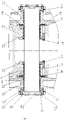
- drawings include the following drawing markers: 10: frame; 11: mounting part; 20: swing bolster; 21: swinging bolster main body; 211: limiting bulge; 212: clamping part; 30: pin shaft; 41: sliding bearing; 42: bearing cover; 43: oil seal member; 44: bush; 45: baffle component; 50: end cover; 51: baffle bulge; 60: observation mirror; 70: antithrust gasket; 80: first sealing ring; 90: second sealing ring; 100: first fastener; 110: second fastener; 120: third fastener; 130: sealant; 140: third sealing ring.
- the bogie includes a frame 10 and a swing bolster 20, and further includes a pin shaft 30, the pin shaft 30 is provided on the frame 10 and the swing bolster 20 in a penetration manner, such that the swing bolster 20 is rotationally provided with respect to the frame 10, the swing bolster 20 includes a swing bolster main body 21, a bottom end of the swing bolster main body 21 is used for connecting to a vehicle body, the pin shaft 30 is provided on a top end of the swing bolster main body 21 in a penetration manner, so as to connect the frame 10 and the swing bolster 20.
- the frame 10 is rotationally connected with the swing bolster 20 by the pin shaft 30, such that the swing bolster 20 is rotationally provided with respect to the frame 10, the bottom end of the swing bolster main body 21 of the swing bolster 20 is connected to the vehicle body, then connection of the bogie with the vehicle body is achieved, the vehicle body is stably suspended on a track, and the problem that in the related art a suspended vehicle cannot be operated on a track stably is solved.
- the bogie further includes a sliding bearing 41, the sliding bearing 41 is provided on the pin shaft 30 in a sleeving manner, and the frame 10 is provided on the pin shaft 30 by the sliding bearing 41. Due to adoption of the sliding bearing 41, connection of the pin shaft 30 with the frame 10 is conveniently achieved, and furthermore the swing bolster 20 is rotationally provided with respect to the frame 10.
- the bogie further includes a bearing cover 42, the bearing cover 42 is mounted on the frame 10, and the bearing cover 42 is provided on the pin shaft 30 in a sleeving manner to shield the sliding bearing 41.
- the bearing cover 42 By mounting the bearing cover 42 on the frame 10, the sliding bearing 41 is fixed in a position of the pin shaft 30.
- the bogie further includes an oil seal member 43, the oil seal member 43 is provided on an inner side of the bearing cover 42, and the oil seal member 43 is provided on the pin shaft 30 in a sleeving manner.
- the bogie further includes a bush 44, the bush 44 is provided on the pin shaft 30 in a sleeving manner, and the bush 44 is provided in an annular gap between the pin shaft 30 and the swing bolster main body 21.
- the bogie further includes a baffle component 45, the baffle component 45 is provided in the annular gap between the pin shaft 30 and the swing bolster main body 21, and the baffle component 45 is provided on both sides of the bush 44.
- the baffle component 45 By providing the baffle component 45, the bush 44 is limited in the gap between the pin shaft 30 and the swing bolster main body 21.
- the baffle component 45 includes two baffle rings, a radial cross section of each of the two baffle ring is of triangle shaped, and the two baffle rings are attached by a respective inclined surface.
- the two baffle rings are connected by the longest side of a respective triangular cross section of the two baffle rings.
- the radial cross section of the each of the two baffle ring is of right triangle shaped, and a right angle side of the radial cross section of the each of the two baffle ring is attached to a peripheral surface of the pin shaft 30.
- the bogie further includes an end cover 50, the end cover 50 is mounted on the swing bolster main body 21, and the end cover 50 is provided on a side wall of the swing bolster main body 21 to shield the pin shaft 30.
- the pin shaft 30 is completely shielded.
- the end cover 50 is provided with a baffle bulge 51, a limiting bulge 211 is provided on the swing bolster main body 21, and the bush 44 and the baffle component 45 are sandwiched between the baffle bulge 51 and the limiting bulge 211.
- the baffle bulge 51 and the limiting bulge 211 By providing the baffle bulge 51 and the limiting bulge 211, positioning of the bush 44 and the baffle component 45 is conveniently achieved.
- the bogie further includes an observation mirror 60, the observation mirror 60 is mounted on the end cover 50 and is used for observing a positioning state of the pin shaft 30.
- a center of an end surface of the pin shaft 30 is marked, a relative position of the marker with respect to the end cover 50 may be observed by the observation mirror 60, furthermore a positioning state of the pin shaft 30 is observed, and assembling precision of the pin shaft 30 is ensured.
- a sealant 130 is sandwiched between the end cover 50 and the swing bolster main body 21.
- two oppositely arranged clamping parts 212 are provided at the top end of the swing bolster main body 21, the frame 10 is provided with a mounting part 11, the mounting part 11 is clamped between the two clamping parts 212, and the pin shaft 30 is provided on the two clamping parts 212 and the mounting part 11 in a penetration manner.
- two mounting parts 11 are provided, the two mounting parts 11 are provided at an interval between the two clamping parts 212, that is, the mounting parts 11 are sandwiched between the two clamping parts 212.
- the bogie further includes an antithrust gasket 70, the antithrust gasket 70 is positioned in a gap between the mounting parts 11 and each of the two clamping parts 212, and the antithrust gasket 70 is provided around the pin shaft 30.
- the antithrust gasket 70 is fixed on the frame 10 by a first fastener 100.
- the antithrust gasket 70 is made of a wearing-resistant material, and the first fastener 100 is a hexagon socket countersunk head screw.
- the bogie further includes a first sealing ring 80, at least a part of the first sealing ring 80 is positioned in the gap between the mounting parts 11 and the clamping parts 212, and the first sealing ring 80 is provided around the antithrust gasket 70.
- an accommodation groove is formed in an outer circumference wall of the first sealing ring 80, and at least a part of a groove opening of the accommodation groove is positioned in the gap between the mounting part 11 and the clamping parts 212.
- the first sealing ring 80 is a V-shaped ring.
- the bogie further includes a second sealing ring 90 which is provided on the bearing cover 42 and a third sealing ring 140 which is provided on the clamping parts 212.
- the second sealing ring 90 and the third sealing ring 140 are O-shaped sealing rings for sealing.
- the bogie further includes a second fastener 110 which is provided on the bearing cover 42 and the mounting parts 11 in the penetration manner, and a third fastener 120 which is provided on the end cover 50 and the clamping parts 212 in the penetration manner.
- a part between the end cover 50 and the clamping parts 212 is filled with the sealant 130.
- An embodiment of the disclosure further provides a suspended vehicle, and the suspended vehicle includes the above bogie.
- the disclosure relates to a mounting structure of a suspending device.
- the structure is provided between the swing bolster 20 and the frame 10.
- An embodiment of the disclosure sufficiently utilizes spatial structures of the frame 10 and the swing bolster 20, processibility of the mounting structure self is utilized, meanwhile, by using wearing-resistant materials such as the sliding bearing 41 and the antithrust gasket, relative rotation and sliding are achieved.
- a triangular antithrust gasket is adopted to extrude the swing bolster and the pin shaft 30.
- the O-shaped rings, the V-shaped ring, the sealant, and the like are adopted for sealing.
- mounting situations of the pin shaft 30 is observed by using the observation mirror 60.
- a loctite adhesive-243 or a Nord-Lock anti-loosening "tooth-shaped" gasket is used.
- the frame is rotationally connected with the swing bolster by the pin shaft, then the swing bolster is rotationally provided with respect to the frame, the bottom end of the swing bolster body of the swing bolster is connected with the vehicle body, furthermore connection of the bogie and the vehicle body is achieved, the vehicle body is stably suspended on the track, and the problem that in the related art the suspended vehicle cannot be operated on the track stably is solved.
Landscapes
- Engineering & Computer Science (AREA)
- Mechanical Engineering (AREA)
- Transportation (AREA)
- Sealing Devices (AREA)
- Rolling Contact Bearings (AREA)
Claims (12)
- Drehgestell, das einen Rahmen (10) und einen Drehschemel (20) umfasst und ferner umfasst:eine Zapfenwelle (30), wobei die Zapfenwelle (30) an dem Rahmen (10) und dem Drehschemel (20) durchdringend vorgesehen ist, so dass der Drehschemel (20) in Bezug auf den Rahmen (10) drehbar vorgesehen ist;wobei der Drehschemel (20) einen Drehschemel-Hauptkörper (21) umfasst; ein unteres Ende des Drehschemel-Hauptkörpers (21) zum Verbinden mit einem Wagenkasten verwendet werden kann; die Zapfenwelle (30) an einem oberen Ende des Drehschemel-Hauptkörpers (21) durchdringend vorgesehen ist, um den Rahmen (10) und den Drehschemel (20) zu verbinden, dadurch gekennzeichnet, dass zwei gegenüberliegend angeordnete Klemmteile (212) an einem oberen Ende des Drehschemel-Hauptkörpers (21) vorgesehen sind, der Rahmen (10) mit einem Befestigungsteil (11) versehen ist, das Befestigungsteil (11) zwischen den zwei Klemmteilen (212) geklemmt ist und die Zapfenwelle (30) an den beiden Klemmteilen (212) und dem Befestigungsteil (11) durchdringend vorgesehen ist;wobei das Drehgestell auch umfasst:eine Anti-Stoß-Dichtung (70), wobei die Anti-Stoß-Dichtung (70) in einem Spalt zwischen dem Befestigungsteil (11) und jedem der zwei Klemmteile (212) positioniert ist, und die Anti-Stoß-Dichtung (70) um die Zapfenwelle (30) herum vorgesehen ist;einen ersten Dichtungsring (80), wobei zumindest ein Teil des ersten Dichtungsrings (80) in dem Spalt zwischen dem Befestigungsteil (11) und jedem der zwei Klemmteile (212) positioniert ist und der erste Dichtungsring (80) um die Anti-Stoß-Dichtung (70) herum vorgesehen ist.
- Drehgestell nach Anspruch 1, das ferner umfasst:
eine Buchse (44), wobei die Buchse (44) auf der Zapfenwelle (30) in einer hülsenartigen Weise vorgesehen ist, und die Buchse (44) in einem ringförmigen Spalt zwischen der Zapfenwelle (30) und dem Drehschemel-Hauptkörper (21) vorgesehen ist. - Drehgestell nach Anspruch 2, das ferner umfasst:
eine Ablenkkomponente (45), wobei die Ablenkkomponente (45) in dem ringförmigen Spalt zwischen der Zapfenwelle (30) und dem Drehschemel-Hauptkörper (21) vorgesehen ist und die Ablenkkomponente (45) auf beiden Seiten der Buchse (44) vorgesehen ist. - Drehgestell nach Anspruch 3, wobei die Ablenkkomponente (45) zwei Ablenkringe umfasst, wobei ein radialer Querschnitt von jedem der zwei Ablenkringe dreieckförmig ist und die zwei Ablenkringe durch eine jeweilige geneigte Oberfläche befestigt sind.
- Drehgestell nach Anspruch 4, wobei der radiale Querschnitt von jedem der zwei Ablenkringe die Form eines rechtwinkligen Dreiecks hat und eine rechtwinklige Seite des radialen Querschnitts von jedem der zwei Ablenkringe an einer Umfangsoberfläche der Zapfenwelle (30) befestigt ist.
- Drehgestell nach Anspruch 3, das ferner umfasst:
eine Endabdeckung (50), wobei die Endabdeckung (50) an dem Drehschemel-Hauptkörper (21) angebracht ist, und die Endabdeckung (50) an einer Seitenwand des Drehschemel-Hauptkörpers (21) zur Abschirmung der Zapfenwelle (30) vorgesehen ist. - Drehgestell nach Anspruch 6, wobei die Endabdeckung (50) mit einer Ablenkwulst (51) versehen ist, eine Begrenzungswulst (211) an dem Drehschemel-Hauptkörper (21) vorgesehen ist und die Buchse (44) und die Ablenkkomponente (45) zwischen der Ablenkwulst (51) und der Begrenzungswulst (211) angeordnet sind.
- Drehgestell nach Anspruch 6, wobei die Endabdeckung (50) gegenüber einer Endfläche der Zapfenwelle (30) vorgesehen ist, das Drehgestell ferner einen Beobachtungsspiegel (60) umfasst, wobei der Beobachtungsspiegel (60) auf der Endabdeckung (50) angebracht ist und zum Beobachten eines Positionierungszustands der Zapfenwelle (30) verwendet wird.
- Drehgestell nach Anspruch 1, das ferner ein Gleitlager (41) umfasst, wobei das Gleitlager (41) auf der Zapfenwelle (30) in einer hülsenartigen Weise vorgesehen ist und der Rahmen (10) auf der Zapfenwelle (30) durch das Gleitlager (41) in einer hülsenartigen Weise vorgesehen ist.
- Drehgestell nach Anspruch 9, das ferner eine Lagerabdeckung (42) umfasst, wobei die Lagerabdeckung (42) an dem Rahmen (10) angebracht ist und die Lagerabdeckung (42) an der Zapfenwelle (30) einer hülsenartigen Weise vorgesehen ist, um das Gleitlager (41) abzuschirmen.
- Drehgestell nach Anspruch 10, das ferner ein Öldichtungselement (43) umfasst, wobei das Öldichtungselement (43) auf einer Innenseite der Lagerabdeckung (42) vorgesehen ist und das Öldichtungselement (43) auf der Zapfenwelle (30) einer hülsenartigen Weise vorgesehen ist.
- Gefedertes Fahrzeug, das ein Drehgestell umfasst, wobei das Drehgestell das Drehgestell nach einem der Ansprüche 1-11 ist.
Applications Claiming Priority (4)
| Application Number | Priority Date | Filing Date | Title |
|---|---|---|---|
| CN201710382301.9A CN107284463B (zh) | 2017-05-25 | 2017-05-25 | 转向架及具有其的悬挂车 |
| CN201710382049.1A CN107323476B (zh) | 2017-05-25 | 2017-05-25 | 转向架及具有其的悬挂车 |
| CN201710377039.9A CN107284462B (zh) | 2017-05-25 | 2017-05-25 | 转向架及具有其的悬挂车 |
| PCT/CN2017/108543 WO2018214403A1 (zh) | 2017-05-25 | 2017-10-31 | 转向架及具有其的悬挂车 |
Publications (3)
| Publication Number | Publication Date |
|---|---|
| EP3527458A1 EP3527458A1 (de) | 2019-08-21 |
| EP3527458A4 EP3527458A4 (de) | 2020-06-24 |
| EP3527458B1 true EP3527458B1 (de) | 2022-08-10 |
Family
ID=64396196
Family Applications (1)
| Application Number | Title | Priority Date | Filing Date |
|---|---|---|---|
| EP17910726.3A Active EP3527458B1 (de) | 2017-05-25 | 2017-10-31 | Drehgestell und gefedertes fahrzeug damit |
Country Status (3)
| Country | Link |
|---|---|
| EP (1) | EP3527458B1 (de) |
| JP (1) | JP6764026B2 (de) |
| WO (1) | WO2018214403A1 (de) |
Family Cites Families (14)
| Publication number | Priority date | Publication date | Assignee | Title |
|---|---|---|---|---|
| US546928A (en) * | 1895-09-24 | langm | ||
| US945750A (en) * | 1909-05-17 | 1910-01-11 | Frank O Butler | Suspension-railway truck. |
| US1944100A (en) * | 1933-08-30 | 1934-01-16 | Peter J Medor | Suspended railway system |
| US3081711A (en) * | 1960-06-27 | 1963-03-19 | Davino Alphonso | Suspended rapid transit constructions |
| US3525306A (en) * | 1967-12-21 | 1970-08-25 | Common Market Trading Corp Ltd | Suspended railway |
| DD110814A1 (de) * | 1974-04-01 | 1975-01-12 | ||
| SU518402A2 (ru) * | 1975-01-10 | 1976-06-25 | Брянский Институт Транспортного Машиностроения | Шкворневой узел дл железнодорожного подвижного состава |
| US5197390A (en) * | 1992-01-30 | 1993-03-30 | Transyt Canada Inc. | Suspended vehicle with orientation adjustment by horizontally translating the pivot point relative to the vertical axis |
| JP4097750B2 (ja) * | 1997-09-24 | 2008-06-11 | 日本ケーブル株式会社 | 索道の椅子式搬器の背板ロック機構 |
| US7124692B2 (en) * | 2002-10-15 | 2006-10-24 | Sky Train Corporation | Overhead suspended transportation system and method |
| CN104442880B (zh) * | 2014-10-15 | 2017-02-22 | 南车株洲电力机车有限公司 | 一种悬挂式单轨列车转向架 |
| CN104228865B (zh) * | 2014-10-15 | 2016-07-06 | 南车株洲电力机车有限公司 | 一种牵引悬挂装置 |
| CN107284463B (zh) * | 2017-05-25 | 2019-03-05 | 中车青岛四方机车车辆股份有限公司 | 转向架及具有其的悬挂车 |
| CN107284462B (zh) * | 2017-05-25 | 2019-08-27 | 中车青岛四方机车车辆股份有限公司 | 转向架及具有其的悬挂车 |
-
2017
- 2017-10-31 EP EP17910726.3A patent/EP3527458B1/de active Active
- 2017-10-31 WO PCT/CN2017/108543 patent/WO2018214403A1/zh not_active Ceased
- 2017-10-31 JP JP2019522356A patent/JP6764026B2/ja active Active
Also Published As
| Publication number | Publication date |
|---|---|
| JP6764026B2 (ja) | 2020-09-30 |
| JP2019532869A (ja) | 2019-11-14 |
| WO2018214403A1 (zh) | 2018-11-29 |
| EP3527458A1 (de) | 2019-08-21 |
| EP3527458A4 (de) | 2020-06-24 |
Similar Documents
| Publication | Publication Date | Title |
|---|---|---|
| CN203463483U (zh) | 密封球节 | |
| EP3106687B1 (de) | Staubabdeckung für ein kugelgelenk | |
| US9863463B2 (en) | Ball joint | |
| BR102013012105B1 (pt) | Conjunto de manga de eixo | |
| CN107284462B (zh) | 转向架及具有其的悬挂车 | |
| EP3527458A1 (de) | Drehgestell und gefedertes fahrzeug damit | |
| US8960689B1 (en) | High misalignment wheel drive | |
| CN107284463B (zh) | 转向架及具有其的悬挂车 | |
| CN105365884A (zh) | 一种汽车前转向驱动桥 | |
| CN105041063A (zh) | 转舌锁及具有其的轨道车辆 | |
| CN203348357U (zh) | 特种车用万向传动轴角度轴总成 | |
| CN107323476B (zh) | 转向架及具有其的悬挂车 | |
| US20060065222A1 (en) | Disassembly aid for sealed components | |
| CN204354762U (zh) | 一种非公路运输车平衡悬架总成 | |
| CN206954239U (zh) | 转向架及具有其的悬挂车 | |
| CN203020007U (zh) | 平衡悬架系统平衡轴、轴衬套与轴壳的定位总成 | |
| JP2019070252A (ja) | 複合ボルト、及び建物の構造体への被支持部材の支持構造 | |
| CN210240299U (zh) | 一种防水防尘自润滑轴承件 | |
| CN207034185U (zh) | 一种车用制动器防尘罩 | |
| CN207034171U (zh) | 一种车用方形橡胶密封圈 | |
| CN217107839U (zh) | 一种轮毂单元 | |
| CN205098272U (zh) | 一种汽车前转向驱动桥 | |
| CN210454316U (zh) | 一种矿车轮的密封装置 | |
| CN213017187U (zh) | 一种组装式内六角紧固螺栓 | |
| CN106801702A (zh) | 悬挂密封铰链装置 |
Legal Events
| Date | Code | Title | Description |
|---|---|---|---|
| STAA | Information on the status of an ep patent application or granted ep patent |
Free format text: STATUS: THE INTERNATIONAL PUBLICATION HAS BEEN MADE |
|
| PUAI | Public reference made under article 153(3) epc to a published international application that has entered the european phase |
Free format text: ORIGINAL CODE: 0009012 |
|
| STAA | Information on the status of an ep patent application or granted ep patent |
Free format text: STATUS: REQUEST FOR EXAMINATION WAS MADE |
|
| 17P | Request for examination filed |
Effective date: 20190513 |
|
| AK | Designated contracting states |
Kind code of ref document: A1 Designated state(s): AL AT BE BG CH CY CZ DE DK EE ES FI FR GB GR HR HU IE IS IT LI LT LU LV MC MK MT NL NO PL PT RO RS SE SI SK SM TR |
|
| AX | Request for extension of the european patent |
Extension state: BA ME |
|
| REG | Reference to a national code |
Ref country code: DE Ref legal event code: R079 Ref document number: 602017060628 Country of ref document: DE Free format text: PREVIOUS MAIN CLASS: B61F0005040000 Ipc: B61B0003000000 |
|
| A4 | Supplementary search report drawn up and despatched |
Effective date: 20200528 |
|
| RIC1 | Information provided on ipc code assigned before grant |
Ipc: B61F 5/16 20060101ALI20200520BHEP Ipc: B61B 3/00 20060101AFI20200520BHEP Ipc: B61F 5/04 20060101ALI20200520BHEP |
|
| DAV | Request for validation of the european patent (deleted) | ||
| DAX | Request for extension of the european patent (deleted) | ||
| GRAP | Despatch of communication of intention to grant a patent |
Free format text: ORIGINAL CODE: EPIDOSNIGR1 |
|
| STAA | Information on the status of an ep patent application or granted ep patent |
Free format text: STATUS: GRANT OF PATENT IS INTENDED |
|
| INTG | Intention to grant announced |
Effective date: 20220516 |
|
| GRAS | Grant fee paid |
Free format text: ORIGINAL CODE: EPIDOSNIGR3 |
|
| GRAA | (expected) grant |
Free format text: ORIGINAL CODE: 0009210 |
|
| STAA | Information on the status of an ep patent application or granted ep patent |
Free format text: STATUS: THE PATENT HAS BEEN GRANTED |
|
| AK | Designated contracting states |
Kind code of ref document: B1 Designated state(s): AL AT BE BG CH CY CZ DE DK EE ES FI FR GB GR HR HU IE IS IT LI LT LU LV MC MK MT NL NO PL PT RO RS SE SI SK SM TR |
|
| REG | Reference to a national code |
Ref country code: AT Ref legal event code: REF Ref document number: 1510332 Country of ref document: AT Kind code of ref document: T Effective date: 20220815 Ref country code: CH Ref legal event code: EP |
|
| REG | Reference to a national code |
Ref country code: IE Ref legal event code: FG4D |
|
| REG | Reference to a national code |
Ref country code: DE Ref legal event code: R096 Ref document number: 602017060628 Country of ref document: DE |
|
| REG | Reference to a national code |
Ref country code: NL Ref legal event code: MP Effective date: 20220810 |
|
| REG | Reference to a national code |
Ref country code: LT Ref legal event code: MG9D |
|
| PG25 | Lapsed in a contracting state [announced via postgrant information from national office to epo] |
Ref country code: SE Free format text: LAPSE BECAUSE OF FAILURE TO SUBMIT A TRANSLATION OF THE DESCRIPTION OR TO PAY THE FEE WITHIN THE PRESCRIBED TIME-LIMIT Effective date: 20220810 Ref country code: RS Free format text: LAPSE BECAUSE OF FAILURE TO SUBMIT A TRANSLATION OF THE DESCRIPTION OR TO PAY THE FEE WITHIN THE PRESCRIBED TIME-LIMIT Effective date: 20220810 Ref country code: PT Free format text: LAPSE BECAUSE OF FAILURE TO SUBMIT A TRANSLATION OF THE DESCRIPTION OR TO PAY THE FEE WITHIN THE PRESCRIBED TIME-LIMIT Effective date: 20221212 Ref country code: NO Free format text: LAPSE BECAUSE OF FAILURE TO SUBMIT A TRANSLATION OF THE DESCRIPTION OR TO PAY THE FEE WITHIN THE PRESCRIBED TIME-LIMIT Effective date: 20221110 Ref country code: NL Free format text: LAPSE BECAUSE OF FAILURE TO SUBMIT A TRANSLATION OF THE DESCRIPTION OR TO PAY THE FEE WITHIN THE PRESCRIBED TIME-LIMIT Effective date: 20220810 Ref country code: LV Free format text: LAPSE BECAUSE OF FAILURE TO SUBMIT A TRANSLATION OF THE DESCRIPTION OR TO PAY THE FEE WITHIN THE PRESCRIBED TIME-LIMIT Effective date: 20220810 Ref country code: LT Free format text: LAPSE BECAUSE OF FAILURE TO SUBMIT A TRANSLATION OF THE DESCRIPTION OR TO PAY THE FEE WITHIN THE PRESCRIBED TIME-LIMIT Effective date: 20220810 Ref country code: FI Free format text: LAPSE BECAUSE OF FAILURE TO SUBMIT A TRANSLATION OF THE DESCRIPTION OR TO PAY THE FEE WITHIN THE PRESCRIBED TIME-LIMIT Effective date: 20220810 |
|
| REG | Reference to a national code |
Ref country code: AT Ref legal event code: MK05 Ref document number: 1510332 Country of ref document: AT Kind code of ref document: T Effective date: 20220810 |
|
| PG25 | Lapsed in a contracting state [announced via postgrant information from national office to epo] |
Ref country code: PL Free format text: LAPSE BECAUSE OF FAILURE TO SUBMIT A TRANSLATION OF THE DESCRIPTION OR TO PAY THE FEE WITHIN THE PRESCRIBED TIME-LIMIT Effective date: 20220810 Ref country code: IS Free format text: LAPSE BECAUSE OF FAILURE TO SUBMIT A TRANSLATION OF THE DESCRIPTION OR TO PAY THE FEE WITHIN THE PRESCRIBED TIME-LIMIT Effective date: 20221210 Ref country code: HR Free format text: LAPSE BECAUSE OF FAILURE TO SUBMIT A TRANSLATION OF THE DESCRIPTION OR TO PAY THE FEE WITHIN THE PRESCRIBED TIME-LIMIT Effective date: 20220810 Ref country code: GR Free format text: LAPSE BECAUSE OF FAILURE TO SUBMIT A TRANSLATION OF THE DESCRIPTION OR TO PAY THE FEE WITHIN THE PRESCRIBED TIME-LIMIT Effective date: 20221111 |
|
| PG25 | Lapsed in a contracting state [announced via postgrant information from national office to epo] |
Ref country code: SM Free format text: LAPSE BECAUSE OF FAILURE TO SUBMIT A TRANSLATION OF THE DESCRIPTION OR TO PAY THE FEE WITHIN THE PRESCRIBED TIME-LIMIT Effective date: 20220810 Ref country code: RO Free format text: LAPSE BECAUSE OF FAILURE TO SUBMIT A TRANSLATION OF THE DESCRIPTION OR TO PAY THE FEE WITHIN THE PRESCRIBED TIME-LIMIT Effective date: 20220810 Ref country code: ES Free format text: LAPSE BECAUSE OF FAILURE TO SUBMIT A TRANSLATION OF THE DESCRIPTION OR TO PAY THE FEE WITHIN THE PRESCRIBED TIME-LIMIT Effective date: 20220810 Ref country code: DK Free format text: LAPSE BECAUSE OF FAILURE TO SUBMIT A TRANSLATION OF THE DESCRIPTION OR TO PAY THE FEE WITHIN THE PRESCRIBED TIME-LIMIT Effective date: 20220810 Ref country code: CZ Free format text: LAPSE BECAUSE OF FAILURE TO SUBMIT A TRANSLATION OF THE DESCRIPTION OR TO PAY THE FEE WITHIN THE PRESCRIBED TIME-LIMIT Effective date: 20220810 Ref country code: AT Free format text: LAPSE BECAUSE OF FAILURE TO SUBMIT A TRANSLATION OF THE DESCRIPTION OR TO PAY THE FEE WITHIN THE PRESCRIBED TIME-LIMIT Effective date: 20220810 |
|
| REG | Reference to a national code |
Ref country code: DE Ref legal event code: R097 Ref document number: 602017060628 Country of ref document: DE |
|
| PG25 | Lapsed in a contracting state [announced via postgrant information from national office to epo] |
Ref country code: SK Free format text: LAPSE BECAUSE OF FAILURE TO SUBMIT A TRANSLATION OF THE DESCRIPTION OR TO PAY THE FEE WITHIN THE PRESCRIBED TIME-LIMIT Effective date: 20220810 Ref country code: MC Free format text: LAPSE BECAUSE OF FAILURE TO SUBMIT A TRANSLATION OF THE DESCRIPTION OR TO PAY THE FEE WITHIN THE PRESCRIBED TIME-LIMIT Effective date: 20220810 Ref country code: EE Free format text: LAPSE BECAUSE OF FAILURE TO SUBMIT A TRANSLATION OF THE DESCRIPTION OR TO PAY THE FEE WITHIN THE PRESCRIBED TIME-LIMIT Effective date: 20220810 |
|
| REG | Reference to a national code |
Ref country code: CH Ref legal event code: PL |
|
| PLBE | No opposition filed within time limit |
Free format text: ORIGINAL CODE: 0009261 |
|
| STAA | Information on the status of an ep patent application or granted ep patent |
Free format text: STATUS: NO OPPOSITION FILED WITHIN TIME LIMIT |
|
| REG | Reference to a national code |
Ref country code: BE Ref legal event code: MM Effective date: 20221031 |
|
| PG25 | Lapsed in a contracting state [announced via postgrant information from national office to epo] |
Ref country code: AL Free format text: LAPSE BECAUSE OF FAILURE TO SUBMIT A TRANSLATION OF THE DESCRIPTION OR TO PAY THE FEE WITHIN THE PRESCRIBED TIME-LIMIT Effective date: 20220810 Ref country code: LU Free format text: LAPSE BECAUSE OF NON-PAYMENT OF DUE FEES Effective date: 20221031 |
|
| 26N | No opposition filed |
Effective date: 20230511 |
|
| PG25 | Lapsed in a contracting state [announced via postgrant information from national office to epo] |
Ref country code: LI Free format text: LAPSE BECAUSE OF NON-PAYMENT OF DUE FEES Effective date: 20221031 Ref country code: FR Free format text: LAPSE BECAUSE OF NON-PAYMENT OF DUE FEES Effective date: 20221031 Ref country code: CH Free format text: LAPSE BECAUSE OF NON-PAYMENT OF DUE FEES Effective date: 20221031 |
|
| PG25 | Lapsed in a contracting state [announced via postgrant information from national office to epo] |
Ref country code: SI Free format text: LAPSE BECAUSE OF FAILURE TO SUBMIT A TRANSLATION OF THE DESCRIPTION OR TO PAY THE FEE WITHIN THE PRESCRIBED TIME-LIMIT Effective date: 20220810 |
|
| PG25 | Lapsed in a contracting state [announced via postgrant information from national office to epo] |
Ref country code: BE Free format text: LAPSE BECAUSE OF NON-PAYMENT OF DUE FEES Effective date: 20221031 |
|
| PG25 | Lapsed in a contracting state [announced via postgrant information from national office to epo] |
Ref country code: IE Free format text: LAPSE BECAUSE OF NON-PAYMENT OF DUE FEES Effective date: 20221031 |
|
| PG25 | Lapsed in a contracting state [announced via postgrant information from national office to epo] |
Ref country code: HU Free format text: LAPSE BECAUSE OF FAILURE TO SUBMIT A TRANSLATION OF THE DESCRIPTION OR TO PAY THE FEE WITHIN THE PRESCRIBED TIME-LIMIT; INVALID AB INITIO Effective date: 20171031 |
|
| PG25 | Lapsed in a contracting state [announced via postgrant information from national office to epo] |
Ref country code: CY Free format text: LAPSE BECAUSE OF FAILURE TO SUBMIT A TRANSLATION OF THE DESCRIPTION OR TO PAY THE FEE WITHIN THE PRESCRIBED TIME-LIMIT Effective date: 20220810 |
|
| PG25 | Lapsed in a contracting state [announced via postgrant information from national office to epo] |
Ref country code: MK Free format text: LAPSE BECAUSE OF FAILURE TO SUBMIT A TRANSLATION OF THE DESCRIPTION OR TO PAY THE FEE WITHIN THE PRESCRIBED TIME-LIMIT Effective date: 20220810 Ref country code: IT Free format text: LAPSE BECAUSE OF FAILURE TO SUBMIT A TRANSLATION OF THE DESCRIPTION OR TO PAY THE FEE WITHIN THE PRESCRIBED TIME-LIMIT Effective date: 20220810 |
|
| PG25 | Lapsed in a contracting state [announced via postgrant information from national office to epo] |
Ref country code: BG Free format text: LAPSE BECAUSE OF FAILURE TO SUBMIT A TRANSLATION OF THE DESCRIPTION OR TO PAY THE FEE WITHIN THE PRESCRIBED TIME-LIMIT Effective date: 20220810 |
|
| PG25 | Lapsed in a contracting state [announced via postgrant information from national office to epo] |
Ref country code: MT Free format text: LAPSE BECAUSE OF FAILURE TO SUBMIT A TRANSLATION OF THE DESCRIPTION OR TO PAY THE FEE WITHIN THE PRESCRIBED TIME-LIMIT Effective date: 20220810 |
|
| PGFP | Annual fee paid to national office [announced via postgrant information from national office to epo] |
Ref country code: GB Payment date: 20250825 Year of fee payment: 9 |
|
| PG25 | Lapsed in a contracting state [announced via postgrant information from national office to epo] |
Ref country code: TR Free format text: LAPSE BECAUSE OF FAILURE TO SUBMIT A TRANSLATION OF THE DESCRIPTION OR TO PAY THE FEE WITHIN THE PRESCRIBED TIME-LIMIT Effective date: 20220810 |
|
| PGFP | Annual fee paid to national office [announced via postgrant information from national office to epo] |
Ref country code: DE Payment date: 20251020 Year of fee payment: 9 |