EP3527408A1 - Method for enhancement of the comfort of a vehicle user - Google Patents
Method for enhancement of the comfort of a vehicle user Download PDFInfo
- Publication number
- EP3527408A1 EP3527408A1 EP18210438.0A EP18210438A EP3527408A1 EP 3527408 A1 EP3527408 A1 EP 3527408A1 EP 18210438 A EP18210438 A EP 18210438A EP 3527408 A1 EP3527408 A1 EP 3527408A1
- Authority
- EP
- European Patent Office
- Prior art keywords
- vehicle
- chassis
- driver
- cab
- sensor system
- Prior art date
- Legal status (The legal status is an assumption and is not a legal conclusion. Google has not performed a legal analysis and makes no representation as to the accuracy of the status listed.)
- Ceased
Links
Images

Classifications
-
- B—PERFORMING OPERATIONS; TRANSPORTING
- B62—LAND VEHICLES FOR TRAVELLING OTHERWISE THAN ON RAILS
- B62D—MOTOR VEHICLES; TRAILERS
- B62D33/00—Superstructures for load-carrying vehicles
- B62D33/077—Superstructures for load-carrying vehicles characterised by the connection of the superstructure to the vehicle frame
-
- B—PERFORMING OPERATIONS; TRANSPORTING
- B60—VEHICLES IN GENERAL
- B60G—VEHICLE SUSPENSION ARRANGEMENTS
- B60G17/00—Resilient suspensions having means for adjusting the spring or vibration-damper characteristics, for regulating the distance between a supporting surface and a sprung part of vehicle or for locking suspension during use to meet varying vehicular or surface conditions, e.g. due to speed or load
- B60G17/015—Resilient suspensions having means for adjusting the spring or vibration-damper characteristics, for regulating the distance between a supporting surface and a sprung part of vehicle or for locking suspension during use to meet varying vehicular or surface conditions, e.g. due to speed or load the regulating means comprising electric or electronic elements
- B60G17/016—Resilient suspensions having means for adjusting the spring or vibration-damper characteristics, for regulating the distance between a supporting surface and a sprung part of vehicle or for locking suspension during use to meet varying vehicular or surface conditions, e.g. due to speed or load the regulating means comprising electric or electronic elements characterised by their responsiveness, when the vehicle is travelling, to specific motion, a specific condition, or driver input
- B60G17/0165—Resilient suspensions having means for adjusting the spring or vibration-damper characteristics, for regulating the distance between a supporting surface and a sprung part of vehicle or for locking suspension during use to meet varying vehicular or surface conditions, e.g. due to speed or load the regulating means comprising electric or electronic elements characterised by their responsiveness, when the vehicle is travelling, to specific motion, a specific condition, or driver input to an external condition, e.g. rough road surface, side wind
-
- B—PERFORMING OPERATIONS; TRANSPORTING
- B60—VEHICLES IN GENERAL
- B60G—VEHICLE SUSPENSION ARRANGEMENTS
- B60G99/00—Subject matter not provided for in other groups of this subclass
- B60G99/002—Suspension details of the suspension of the vehicle body on the vehicle chassis
-
- B—PERFORMING OPERATIONS; TRANSPORTING
- B62—LAND VEHICLES FOR TRAVELLING OTHERWISE THAN ON RAILS
- B62D—MOTOR VEHICLES; TRAILERS
- B62D33/00—Superstructures for load-carrying vehicles
- B62D33/06—Drivers' cabs
- B62D33/0604—Cabs insulated against vibrations or noise, e.g. with elastic suspension
-
- B—PERFORMING OPERATIONS; TRANSPORTING
- B60—VEHICLES IN GENERAL
- B60G—VEHICLE SUSPENSION ARRANGEMENTS
- B60G2300/00—Indexing codes relating to the type of vehicle
- B60G2300/02—Trucks; Load vehicles
- B60G2300/026—Heavy duty trucks
-
- B—PERFORMING OPERATIONS; TRANSPORTING
- B60—VEHICLES IN GENERAL
- B60G—VEHICLE SUSPENSION ARRANGEMENTS
- B60G2400/00—Indexing codes relating to detected, measured or calculated conditions or factors
- B60G2400/10—Acceleration; Deceleration
- B60G2400/102—Acceleration; Deceleration vertical
-
- B—PERFORMING OPERATIONS; TRANSPORTING
- B60—VEHICLES IN GENERAL
- B60G—VEHICLE SUSPENSION ARRANGEMENTS
- B60G2400/00—Indexing codes relating to detected, measured or calculated conditions or factors
- B60G2400/20—Speed
- B60G2400/204—Vehicle speed
-
- B—PERFORMING OPERATIONS; TRANSPORTING
- B60—VEHICLES IN GENERAL
- B60G—VEHICLE SUSPENSION ARRANGEMENTS
- B60G2400/00—Indexing codes relating to detected, measured or calculated conditions or factors
- B60G2400/25—Stroke; Height; Displacement
- B60G2400/252—Stroke; Height; Displacement vertical
-
- B—PERFORMING OPERATIONS; TRANSPORTING
- B60—VEHICLES IN GENERAL
- B60G—VEHICLE SUSPENSION ARRANGEMENTS
- B60G2400/00—Indexing codes relating to detected, measured or calculated conditions or factors
- B60G2400/50—Pressure
- B60G2400/51—Pressure in suspension unit
- B60G2400/518—Pressure in suspension unit in damper
-
- B—PERFORMING OPERATIONS; TRANSPORTING
- B60—VEHICLES IN GENERAL
- B60G—VEHICLE SUSPENSION ARRANGEMENTS
- B60G2400/00—Indexing codes relating to detected, measured or calculated conditions or factors
- B60G2400/90—Other conditions or factors
- B60G2400/95—Position of vehicle body elements
-
- B—PERFORMING OPERATIONS; TRANSPORTING
- B60—VEHICLES IN GENERAL
- B60G—VEHICLE SUSPENSION ARRANGEMENTS
- B60G2401/00—Indexing codes relating to the type of sensors based on the principle of their operation
- B60G2401/14—Photo or light sensitive means, e.g. Infrared
-
- B—PERFORMING OPERATIONS; TRANSPORTING
- B60—VEHICLES IN GENERAL
- B60G—VEHICLE SUSPENSION ARRANGEMENTS
- B60G2401/00—Indexing codes relating to the type of sensors based on the principle of their operation
- B60G2401/15—Doppler effect
-
- B—PERFORMING OPERATIONS; TRANSPORTING
- B60—VEHICLES IN GENERAL
- B60G—VEHICLE SUSPENSION ARRANGEMENTS
- B60G2401/00—Indexing codes relating to the type of sensors based on the principle of their operation
- B60G2401/17—Magnetic/Electromagnetic
- B60G2401/174—Radar
-
- B—PERFORMING OPERATIONS; TRANSPORTING
- B60—VEHICLES IN GENERAL
- B60G—VEHICLE SUSPENSION ARRANGEMENTS
- B60G2401/00—Indexing codes relating to the type of sensors based on the principle of their operation
- B60G2401/17—Magnetic/Electromagnetic
- B60G2401/176—Radio or audio sensitive means, e.g. Ultrasonic
Definitions
- the present invention relates to a method for increasing the comfort of a vehicle user of a vehicle having the features of claim 1, a control device for a vehicle having the features of claim 7, a vehicle having the features of claim 8, a computer program product having the features of claim 9 and a computer readable medium having the features of claim 10.
- driver's cab In trucks, it is common that in addition to the chassis and the driver's cab (also referred to as driver's cab) is mounted on spring-damper units. In order to increase the comfort of the vehicle user, who is located in the driver's cab, this is advantageous because the vehicle user is in the driver's cab for a very long time when driving with the truck.
- a towing vehicle which has a movably mounted driver's cab.
- a damping device is arranged between the driver's cab and a base frame.
- a detection device detects movements of the driver's cab, for example in the vertical direction. The movement can be determined, for example, from a stroke or a roll of the driver's cab. In addition, an acceleration can be determined.
- An adjusting device is controlled as a function of the determined movement of the driver's cab, so that a damping in terms of ride comfort is improved.
- the object of the present invention is to propose an alternative possibility for increasing the comfort of a vehicle user of a vehicle.
- the present invention proposes, based on the above object, a method for enhancing comfort of a vehicle user of a vehicle according to claim 1, a control device for a vehicle according to claim 7, a vehicle according to claim 8, a computer program product according to claim 9 and a computer readable medium according to claim 10 in front.
- a sensor system of the vehicle detects movement of a chassis or chassis of the vehicle. Based on the sensor data, a roadway excitation is determined.
- a control device which is connected to the sensor system, controls, based on the roadway excitation, a driver's cab storage of the vehicle, wherein the driver's cab storage is connected to the control device.
- the driver's cab storage is actuated in a dead time between the roadway excitation and a reaction of a driver's cab of the vehicle such that the response of the driver's cab to the roadway excitation is mitigated.
- the vehicle may be, for example, a commercial vehicle, an agricultural machine or a car.
- the vehicle is a commercial vehicle.
- the vehicle has the sensor system.
- This sensor system may include, for example, acceleration sensors, speed sensors, level sensors, pressure sensors, optical sensors and / or displacement sensors.
- the sensor system can be arranged on the chassis of the vehicle and / or on the chassis of the vehicle.
- individual sensors of the sensor system can be arranged on the chassis and other sensors of the sensor system on the chassis of the vehicle.
- individual sensors of the sensor system or the entire sensor system can be arranged on a wheel carrier of the vehicle.
- individual sensors of the sensor system or the sensor system can be arranged on the chassis side of the driver's cab storage.
- individual sensors of the sensor system or the sensor system can be arranged on a frontal area of the chassis.
- the frontal area is the area of the chassis, which is arranged on a vehicle front.
- acceleration sensors may be arranged on the wheel carriers of the vehicle.
- the sensor system is connected to the control device of the vehicle. This connection is such that a data exchange between the controller and the sensor system can take place.
- the sensor system can be designed such that it carries out an evaluation of the data determined by it itself. To For this purpose, the sensor system may have its own control device. Alternatively, the evaluation of the determined data can be carried out by the central control device of the vehicle.
- the connection between the control device of the vehicle and the sensor system can be wired or wirelessly formed.
- the controller may be, for example, an ECU or domain ECU.
- the vehicle also has the driver's cab.
- This is stored by means of the driver's cab storage on the chassis of the vehicle.
- the chassis of the vehicle is connected to the chassis of the vehicle.
- the cab storage is designed as active cab storage. That is, the driver's cab storage has an actuator by means of which a damping of the driver's cab storage can be actuated. That is, the strength of this damping can be adjusted as needed.
- the driver's cab storage can be formed by means of active spring-damper modules.
- the cab storage is connected to the controller. More specifically, the controller is connected to the driver cab storage actuator. This connection is designed such that a data exchange can take place.
- the connection can be either wired or wireless.
- the vehicle has at least one damper or at least one spring-damper module per wheel on its chassis.
- the landing gear may have at least one CDC damper / continuous damping control per wheel. These are also active, i. formed actuatable.
- a movement of the chassis and / or the chassis of the vehicle is first determined by means of the sensor system.
- the movement is determined on the unsprung masses of the chassis, z. B. on a wheel or on a handlebar of the chassis. It can be determined either the movement of the chassis or the movement of the chassis. Alternatively, both the movement of the chassis and the movement of the chassis can be determined.
- the sensor system or individual sensors of the sensor system are arranged on at least one component of the chassis and / or on at least one component of the chassis. Depending on which type of movement is determined, the shape of the sensor system is different.
- the movement that is detected by the sensor system is formed by a vertical acceleration or a vertical speed of the chassis and / or the chassis.
- the sensor system has at least one acceleration sensor or at least one speed sensor which is arranged on the chassis or on the chassis.
- the sensor system continuously determines by means of its at least one acceleration sensor vertical acceleration of the chassis and / or the chassis, depending on where it is arranged.
- the sensor system determines by means of its at least one speed sensor, a vertical speed of the chassis and / or the chassis, depending on where it is arranged.
- the sensor system may detect both the speed and acceleration of the chassis and / or the chassis.
- the movement which is determined by the sensor system, formed by a change in distance of the chassis and / or the chassis to the roadway. That is, the sensor system is designed such that it can continuously determine a distance to the road surface of the component of the chassis and / or the chassis on which it is arranged, and thus can determine the change in the distance.
- the sensor system can have, for example, at least one ultrasonic sensor, at least one infrared sensor, at least one lidar system, at least one radar system, or at least one other suitable sensor for distance measurement.
- at least one sensor for distance measurement can be arranged on several components of the chassis. For example, a sensor for distance measurement can be arranged on each wheel carrier of the chassis.
- the movement which is determined by the sensor system is designed as a relative movement between the chassis and the chassis.
- the sensor system for this purpose at least one level sensor respectively.
- the relative movement between chassis and chassis is that movement, which is caused for example by a pitch of the vehicle.
- the relative movement is determined continuously.
- the level sensors are standard level sensors, which are already used in vehicles when z. B. an automatic readjustment of a headlight should be made.
- the movement which is determined by the sensor system is formed by a piston travel of at least one damper of the chassis.
- at least one of the dampers has at least one displacement sensor which continuously determines the piston travel of the damper.
- either the absolute piston travel or only the change of the piston travel can be determined.
- the sensor system has at least one displacement sensor.
- the piston stroke of each damper of the chassis can be determined, in which case each damper has at least one displacement sensor.
- the movement which is determined by the sensor system, formed by a pressure of at least one damper of the chassis.
- at least one of the dampers of the chassis on at least one pressure sensor, which determines the pressure continuously either relatively or absolutely.
- the sensor system has at least one pressure sensor.
- the pressure of each damper of the chassis can be determined, in which case each damper has at least one pressure sensor.
- the movement can either be determined according to only one of the variants just mentioned or according to a combination of several of the variants just mentioned. In a combination of the variants, it is advantageous that a plausibility check of the sensor data can take place in order to avoid errors in the method.
- the movement is determined continuously, ie over the entire course of the journey.
- This lane excitation is the vibration excitation that arises due to the drive of the vehicle along the roadway. This roadway excitation would be transferred unchanged in an unsprung and undamped system but offset in time to the driver's cab.
- the roadway excitation which is caused by the driving of the vehicle by a road surface unevenness, is forwarded from the wheel of the vehicle to the chassis of the vehicle. From the chassis of the vehicle, this is forwarded to the chassis of the vehicle. The chassis then forwards the roadway excitation to the driver's cab. Until the roadway excitation is relayed from the wheel to the cab, a time lag occurs called dead time. In this dead time, the lane excitation is therefore not yet forwarded to the driver's cab, so the driver's cab is not yet responding to the roadway excitation.
- the roadway excitation can be determined by means of the sensor data relating to the movement of the chassis or of the chassis either by the sensor system itself or by the control device.
- the control device preferably determines the roadway excitation.
- the roadway excitation is determined continuously during a drive of the vehicle.
- the control device controls the driver's cab storage of the vehicle based on the roadway excitation. More specifically, the controller controls the actuator system of the driver's cab storage of the vehicle.
- the driver's cab storage of the vehicle is actuated such that the response of the driver's cab to the roadway excitation is mitigated.
- the reaction of the driver's cab to the roadway excitation is so attenuated that the roadway excitation is not forwarded to the driver's cab.
- the response of the driver's cab is zero, ie the driver's cab is not vibrated.
- This actuation occurs within the dead time between the roadway excitation and the driver's cabin reaction. The actuation takes place continuously while the vehicle is running.
- the vehicle user thus acts less vibrations or no vibrations, although a roadway excitation exists. This is also known as sky-hook control.
- the comfort of the vehicle user, who is located in the driver's cab, is significantly increased compared to a conventional vehicle with a driver's cab.
- Another advantage of the presented method is that the sensor system can be used, which is already present in the vehicle, for. B. the sensor system of the damper of the chassis.
- the process can be implemented inexpensively, since no additional sensor is needed.
- a control device for a vehicle is connectable to a sensor system of the vehicle and to a driver's cab mounting of the vehicle. This has already been described in the previous description. Connectable means that the control device can be connected to the sensor system of the vehicle and to the driver's cab support of the vehicle. This connection is always such that a data exchange can take place.
- the control means comprises means adapted to carry out the steps of the method already described in the previous description.
- the controller is formed as an ECU or a domain ECU.
- the control device preferably comprises computer program code for carrying out the method.
- the control device is part of a vehicle control or a separate control device, for example.
- a vehicle has a driver's cab, a driver's cab storage and a sensor system.
- the vehicle has a control device which has already been described in the previous description.
- the control device is connected to the sensor system of the vehicle and to the driver's cab mounting of the vehicle. This has already been described in the previous description.
- a computer program product includes instructions that cause the controller already described in the previous description to perform the method steps of the method already described in the previous description.
- a computer readable medium comprises a computer program product already described in the previous description.
- the term "computer-readable medium” z. As hard disks and / or servers and / or memory sticks and / or flash memory and / or DVDs and / or Bluerays and / or CDs and / or a downloadable data stream to understand.
- Fig. 1 shows a schematic representation of a vehicle 1 and a roadway excitation after aJohnsbespiel. It is a simplified sectional view of the vehicle 1 shown.
- the vehicle 1 has a chassis 2, a chassis 3 and a driver's cab 5.
- the driver's cab 5 is connected to the chassis 3 by means of the driver's cab support 4.
- the chassis 2 is connected by means of several dampers 8 to the chassis 3. Of these dampers 8, only one is shown here for the sake of clarity. More specifically, here is a wheel 6 of the vehicle 1 is connected at its wheel by means of a damper 8 to the chassis 3.
- the vehicle 1 is on the roadway 9.
- the vehicle 1 also has the control device 7.
- This control device 7 is connected to the driver's cab support 4 and to a sensor system (not shown) on the damper 8. This connection is such that a data exchange between the control device 7 and the actuator system of the driver's cab storage 4 and the sensor system of the damper 8 can take place.
- the control device 7 can thus control the actuator system of the driver's cab storage 4.
- the control device 7 can receive data from the sensor system.
- the sensor system has z. B. way sensors that can determine a piston stroke of the damper 8.
- the sensor system may include pressure sensors that can detect a pressure change of the damper 8.
- the sensor system may include acceleration sensors or speed sensors disposed on the damper 8, which may detect a speed or an acceleration of the damper 8 in a vertical direction. In other words, a movement of the damper 8 in a vertical direction is determined. Based on this movement, a roadway excitation can be determined.
- the vibration amplitudes A are plotted over the time t.
- the roadway excitation which is introduced into the chassis 2, shown.
- the reaction of the cab 5 is shown on this roadway excitation.
- This time offset is referred to as dead time To.
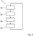
- Fig. 2 shows a schematic representation of a process flow according to an embodiment.
- the method V is illustrated with a total of four method steps 101, 102, 103 and 104.
- the sensor system determines of the vehicle 1, a movement of the chassis 2 and / or a movement of the chassis.
- control device 7 determines a roadway excitation based on the sensor data.
- control device 7 controls the actuator system of the driver's cab support 4 on the basis of this roadway excitation.
- a fourth step 104 the driver's cab support 4 is actuated such that a reaction of the driver's cab 5 to the roadway excitation is mitigated or even prevented.
- This actuation takes place in the dead time To between the roadway excitation and the reaction of the driver's cab 5 to this roadway excitation.
- the driver's cab support 4 is actuated in such a way that it counteracts the roadway excitation.
- the vibrations transmitted to the cab 5 are alleviated or prevented.
- the actuation of the driver's cab storage 4 takes place continuously. That is, the sensor system of the vehicle 1 continuously detects the movement of the chassis 2 or the chassis 3, as shown in the first step 101. Thereafter, the roadway excitation is continuously determined based on the sensor data, as shown in the second step 102.
- the control device 7 continuously controls the actuator system of the driver's cab storage 4, as shown in the third step 103.
- the driver's cab support 4 is continuously actuated in the dead time To between the roadway excitation and the reaction of the driver's cab 5 to the roadway excitation.
- An advantage of the method V shown here is that sensor systems that are already present in the vehicle 1 can be used. As a result, the method V can be implemented inexpensively.
Abstract
Bei einem Verfahren (V) zur Steigerung eines Komforts eines Fahrzeugnutzers eines Fahrzeugs (F) ermittelt zuerst ein Sensorsystem des Fahrzeugs (1) eine Bewegung eines Fahrwerks (2) und/oder eines Chassis (3) des Fahrzeugs (1). Ausgehend von den Sensordaten wird eine Fahrbahnanregung bestimmt. Eine Steuereinrichtung (7), die mit dem Sensorsystem verbunden ist, steuert ausgehend von der Fahrbahnanregung eine Fahrerkabinen-Lagerung (4) des Fahrzeugs (1) an, wobei die Fahrerkabinen-Lagerung (4) mit der Steuereinrichtung (7) verbunden ist. Die Fahrerkabinen-Lagerung (4) wird in einer Totzeit (To) zwischen der Fahrbahnanregung und einer Reaktion einer Fahrerkabine (5) des Fahrzeugs (1) derart aktuiert, dass die Reaktion der Fahrerkabine (5) auf die Fahrbahnanregung abgeschwächt wird.In a method (V) for increasing the comfort of a vehicle user of a vehicle (F), a sensor system of the vehicle (1) first determines a movement of a chassis (2) and / or a chassis (3) of the vehicle (1). A roadway excitation is determined based on the sensor data. A control device (7), which is connected to the sensor system, controls a driver's cab mounting (4) of the vehicle (1) based on the roadway excitation, the driver's cab mounting (4) being connected to the control device (7). The driver's cab mounting (4) is actuated in a dead time (To) between the road stimulation and a reaction of a driver's cab (5) of the vehicle (1) in such a way that the reaction of the driver's cab (5) to the road stimulation is weakened.
Description
Die vorliegende Erfindung betrifft ein Verfahren zur Steigerung eines Komforts eines Fahrzeugnutzers eines Fahrzeugs mit den Merkmalen nach Anspruch 1, eine Steuereinrichtung für ein Fahrzeug mit den Merkmalen nach Anspruch 7, ein Fahrzeug mit den Merkmalen nach Anspruch 8, ein Computerprogrammprodukt mit den Merkmalen nach Anspruch 9 und ein computerlesbares Medium mit den Merkmalen nach Anspruch 10.The present invention relates to a method for increasing the comfort of a vehicle user of a vehicle having the features of claim 1, a control device for a vehicle having the features of
Bei LKWs ist es üblich, dass neben dem Fahrwerk auch die Fahrerkabine (auch als Fahrerhaus bezeichnet) über Feder-Dämpfer-Einheiten gelagert ist. Um den Komfort des Fahrzeugnutzers, der sich in der Fahrerkabine befindet, zu erhöhen, ist dies vorteilhaft, da sich der Fahrzeugnutzer bei einer Fahrt mit dem LKW über einen sehr langen Zeitraum in der Fahrerkabine befindet.In trucks, it is common that in addition to the chassis and the driver's cab (also referred to as driver's cab) is mounted on spring-damper units. In order to increase the comfort of the vehicle user, who is located in the driver's cab, this is advantageous because the vehicle user is in the driver's cab for a very long time when driving with the truck.
Aus
Der vorliegenden Erfindung liegt ausgehend vom Stand der Technik die Aufgabe zu Grunde, eine alternative Möglichkeit zur Steigerung des Komforts eines Fahrzeugnutzers eines Fahrzeugs vorzuschlagen.The object of the present invention, based on the prior art, is to propose an alternative possibility for increasing the comfort of a vehicle user of a vehicle.
Die vorliegende Erfindung schlägt ausgehend von der vorgenannten Aufgabe ein Verfahren zur Steigerung eines Komforts eines Fahrzeugnutzers eines Fahrzeugs nach Anspruch 1, eine Steuereinrichtung für ein Fahrzeug nach Anspruch 7, ein Fahrzeug nach Anspruch 8, ein Computerprogrammprodukt nach Anspruch 9 und ein computerlesbares Medium nach Anspruch 10 vor.The present invention proposes, based on the above object, a method for enhancing comfort of a vehicle user of a vehicle according to claim 1, a control device for a vehicle according to
Bei einem Verfahren zur Steigerung eines Komforts eines Fahrzeugnutzers eines Fahrzeugs ermittelt zuerst ein Sensorsystem des Fahrzeugs eine Bewegung eines Fahrwerks oder Chassis des Fahrzeugs. Ausgehend von den Sensordaten wird eine Fahrbahnanregung bestimmt. Eine Steuereinrichtung, die mit dem Sensorsystem verbunden ist, steuert ausgehend von der Fahrbahnanregung eine Fahrerkabinen-Lagerung des Fahrzeugs an, wobei die Fahrerkabinen-Lagerung mit der Steuereinrichtung verbunden ist. Die Fahrerkabinen-Lagerung wird in einer Totzeit zwischen der Fahrbahnanregung und einer Reaktion einer Fahrerkabine des Fahrzeugs derart aktuiert, dass die Reaktion der Fahrerkabine auf die Fahrbahnanregung abgeschwächt wird. Das Fahrzeug kann beispielsweise ein NKW, eine Landmaschine oder PKW sein. Vorzugsweise ist das Fahrzeug ein NKW.In a method for enhancing a comfort of a vehicle user of a vehicle, first, a sensor system of the vehicle detects movement of a chassis or chassis of the vehicle. Based on the sensor data, a roadway excitation is determined. A control device, which is connected to the sensor system, controls, based on the roadway excitation, a driver's cab storage of the vehicle, wherein the driver's cab storage is connected to the control device. The driver's cab storage is actuated in a dead time between the roadway excitation and a reaction of a driver's cab of the vehicle such that the response of the driver's cab to the roadway excitation is mitigated. The vehicle may be, for example, a commercial vehicle, an agricultural machine or a car. Preferably, the vehicle is a commercial vehicle.
Das Fahrzeug weist das Sensorsystem auf. Dieses Sensorsystem kann beispielsweise Beschleunigungssensoren, Geschwindigkeitssensoren, Höhenstandssensoren, Drucksensoren, optische Sensoren und/oder Wegsensoren umfassen. Das Sensorsystem kann dabei an dem Fahrwerk des Fahrzeugs angeordnet sein und/oder an dem Chassis des Fahrzeugs. Selbstverständlich können einzelne Sensoren des Sensorsystems an dem Chassis und andere Sensoren des Sensorsystems an dem Fahrwerk des Fahrzeugs angeordnet sein. Beispielsweise können an einem Radträger des Fahrzeugs einzelne Sensoren des Sensorsystems oder das gesamte Sensorsystem angeordnet sein. Zusätzlich oder alternativ dazu können an der Chassis-Seite der Fahrerkabinen-Lagerung einzelne Sensoren des Sensorsystems oder das Sensorsystem angeordnet sein. Zusätzlich oder alternativ dazu können an einem Frontalbereich des Chassis einzelne Sensoren des Sensorsystems oder das Sensorsystem angeordnet sein. Der Frontalbereich ist dabei der Bereich des Chassis, der an einer Fahrzeugfront angeordnet ist. Vorzugsweise können Beschleunigungssensoren an den Radträgern des Fahrzeugs angeordnet sein.The vehicle has the sensor system. This sensor system may include, for example, acceleration sensors, speed sensors, level sensors, pressure sensors, optical sensors and / or displacement sensors. The sensor system can be arranged on the chassis of the vehicle and / or on the chassis of the vehicle. Of course, individual sensors of the sensor system can be arranged on the chassis and other sensors of the sensor system on the chassis of the vehicle. For example, individual sensors of the sensor system or the entire sensor system can be arranged on a wheel carrier of the vehicle. Additionally or alternatively, individual sensors of the sensor system or the sensor system can be arranged on the chassis side of the driver's cab storage. Additionally or alternatively, individual sensors of the sensor system or the sensor system can be arranged on a frontal area of the chassis. The frontal area is the area of the chassis, which is arranged on a vehicle front. Preferably, acceleration sensors may be arranged on the wheel carriers of the vehicle.
Das Sensorsystem ist mit der Steuereinrichtung des Fahrzeugs verbunden. Diese Verbindung ist derart, dass ein Datenaustausch zwischen der Steuereinrichtung und dem Sensorsystem stattfinden kann. Das Sensorsystem kann derart ausgeformt sein, dass dieses eine Auswertung der von ihm ermittelten Daten selbst ausführt. Zu diesem Zweck kann das Sensorsystem eine eigene Steuervorrichtung aufweisen. Alternativ dazu kann die Auswertung der ermittelten Daten von der zentralen Steuereinrichtung des Fahrzeugs ausgeführt werden. Die Verbindung zwischen der Steuereinrichtung des Fahrzeugs und dem Sensorsystem kann kabelgebunden oder drahtlos ausgeformt sein. Die Steuereinrichtung kann beispielsweise ein ECU oder Domain-ECU sein.The sensor system is connected to the control device of the vehicle. This connection is such that a data exchange between the controller and the sensor system can take place. The sensor system can be designed such that it carries out an evaluation of the data determined by it itself. To For this purpose, the sensor system may have its own control device. Alternatively, the evaluation of the determined data can be carried out by the central control device of the vehicle. The connection between the control device of the vehicle and the sensor system can be wired or wirelessly formed. The controller may be, for example, an ECU or domain ECU.
Das Fahrzeug weist weiterhin die Fahrerkabine auf. Diese ist mittels der Fahrerkabinen-Lagerung an dem Chassis des Fahrzeugs gelagert. Das Chassis des Fahrzeugs ist verbunden mit dem Fahrwerk des Fahrzeugs. Die Fahrerkabinen-Lagerung ist als aktive Fahrerkabinen-Lagerung ausgeformt. Das heißt, dass die Fahrerkabinen-Lagerung eine Aktuatorik aufweist, mittels welcher eine Dämpfung der Fahrerkabinen-Lagerung aktuiert werden kann. Das heißt, es kann die Stärke dieser Dämpfung bedarfsgerecht eingestellt werden. Beispielsweise kann die Fahrerkabinen-Lagerung mittels aktiven Feder-Dämpfer-Modulen ausgeformt sein. Die Fahrerkabinen-Lagerung ist mit der Steuereinrichtung verbunden. Genauer gesagt ist die Steuereinrichtung mit der Aktuatorik der Die Fahrerkabinen-Lagerung verbunden. Diese Verbindung ist derart ausgeformt, dass ein Datenaustausch erfolgen kann. Die Verbindung kann entweder kabelgebunden oder drahtlos ausgeformt sein.The vehicle also has the driver's cab. This is stored by means of the driver's cab storage on the chassis of the vehicle. The chassis of the vehicle is connected to the chassis of the vehicle. The cab storage is designed as active cab storage. That is, the driver's cab storage has an actuator by means of which a damping of the driver's cab storage can be actuated. That is, the strength of this damping can be adjusted as needed. For example, the driver's cab storage can be formed by means of active spring-damper modules. The cab storage is connected to the controller. More specifically, the controller is connected to the driver cab storage actuator. This connection is designed such that a data exchange can take place. The connection can be either wired or wireless.
Das Fahrzeug weist an seinem Fahrwerk wenigstens einen Dämpfer oder wenigstens ein Feder-Dämpfer-Modul pro Rad auf. Beispielsweise kann das Fahrwerk wenigstens einen CDC-Dämpfer /Continuous Damping Control) pro Rad aufweisen. Diese sind ebenfalls aktiv, d.h. aktuierbar ausgeformt.The vehicle has at least one damper or at least one spring-damper module per wheel on its chassis. For example, the landing gear may have at least one CDC damper / continuous damping control per wheel. These are also active, i. formed actuatable.
Um den Komfort des Fahrzeugnutzers, der sich während einer Fahrt mit dem Fahrzeug in der Fahrerkabine aufhält, zu steigern, wird zuerst mittels des Sensorsystems eine Bewegung des Fahrwerks und/oder des Chassis des Fahrzeugs ermittelt. Beispielsweise wird die Bewegung an den ungefederten Massen des Fahrwerks ermittelt, z. B. an einem Radträger oder an einem Lenker des Fahrwerks. Es kann entweder die Bewegung des Fahrwerks ermittelt werden oder die Bewegung des Chassis. Alternativ dazu kann sowohl die Bewegung des Fahrwerks als auch die Bewegung des Chassis ermittelt werden. Das Sensorsystem oder einzelne Sensoren des Sensorsystems sind dabei an wenigstens einem Bauelement des Fahrwerks und/oder an wenigstens einem Bauelement des Chassis angeordnet. Je nachdem, welche Art der Bewegung ermittelt wird, ist die Ausformung des Sensorsystems eine andere.In order to increase the comfort of the vehicle user, who is staying in the cab while driving with the vehicle, a movement of the chassis and / or the chassis of the vehicle is first determined by means of the sensor system. For example, the movement is determined on the unsprung masses of the chassis, z. B. on a wheel or on a handlebar of the chassis. It can be determined either the movement of the chassis or the movement of the chassis. Alternatively, both the movement of the chassis and the movement of the chassis can be determined. The sensor system or individual sensors of the sensor system are arranged on at least one component of the chassis and / or on at least one component of the chassis. Depending on which type of movement is determined, the shape of the sensor system is different.
In einer ersten Variante ist die Bewegung, die durch das Sensorsystem ermittelt wird, durch eine vertikale Beschleunigung oder eine vertikale Geschwindigkeit des Fahrwerks und/ oder des Chassis ausgebildet. Das heißt, dass das Sensorsystem wenigstens einen Beschleunigungssensor oder wenigstens einen Geschwindigkeitssensor aufweist, der an dem Fahrwerk oder an dem Chassis angeordnet ist. Das Sensorsystem ermittelt kontinuierlich mittels seines wenigstens einen Beschleunigungssensors eine vertikale Beschleunigung des Fahrwerks und/oder des Chassis, je nachdem, wo dieser angeordnet ist. Alternativ dazu ermittelt das Sensorsystem mittels seines wenigstens einen Geschwindigkeitssensors eine vertikale Geschwindigkeit des Fahrwerks und/oder des Chassis, je nachdem, wo dieser angeordnet ist. Wiederum alternativ dazu kann das Sensorsystem sowohl die Geschwindigkeit als auch die Beschleunigung des Fahrwerks und/oder des Chassis ermitteln.In a first variant, the movement that is detected by the sensor system is formed by a vertical acceleration or a vertical speed of the chassis and / or the chassis. This means that the sensor system has at least one acceleration sensor or at least one speed sensor which is arranged on the chassis or on the chassis. The sensor system continuously determines by means of its at least one acceleration sensor vertical acceleration of the chassis and / or the chassis, depending on where it is arranged. Alternatively, the sensor system determines by means of its at least one speed sensor, a vertical speed of the chassis and / or the chassis, depending on where it is arranged. Again alternatively, the sensor system may detect both the speed and acceleration of the chassis and / or the chassis.
In einer weiteren Variante ist die Bewegung, die durch das Sensorsystem ermittelt wird, durch eine Abstandänderung des Fahrwerks und/ oder des Chassis zur Fahrbahn ausgebildet. Das heißt, dass das Sensorsystem derart ausgebildet ist, dass es einen Abstand zur Fahrbahn des Bauelements des Fahrwerks und/oder des Chassis, an dem es angeordnet ist, kontinuierlich ermitteln kann und somit die Änderung des Abstands feststellen kann. Dazu kann das Sensorsystem beispielsweise wenigstens einen Ultraschallsensor, wenigstens einen Infrarotsensor, wenigstens ein Lidarsystem, wenigstens ein Radarsystem, oder wenigstens einen anderen geeigneten Sensor zur Abstandsmessung aufweisen. Selbstverständlich kann an mehreren Bauelementen des Fahrwerks wenigstens ein Sensor zur Abstandsmessung angeordnet sein. Zum Beispiel kann an jedem Radträger des Fahrwerks ein Sensor zur Abstandsmessung angeordnet sein.In a further variant, the movement, which is determined by the sensor system, formed by a change in distance of the chassis and / or the chassis to the roadway. That is, the sensor system is designed such that it can continuously determine a distance to the road surface of the component of the chassis and / or the chassis on which it is arranged, and thus can determine the change in the distance. For this purpose, the sensor system can have, for example, at least one ultrasonic sensor, at least one infrared sensor, at least one lidar system, at least one radar system, or at least one other suitable sensor for distance measurement. Of course, at least one sensor for distance measurement can be arranged on several components of the chassis. For example, a sensor for distance measurement can be arranged on each wheel carrier of the chassis.
In einer weiteren Variante ist die Bewegung, die durch das Sensorsystem ermittelt wird, als eine Relativbewegung zwischen Chassis und Fahrwerk ausgebildet. Beispielsweise kann das Sensorsystem zu diesem Zweck wenigstens einen Höhenstandssensor aufweisen. Die Relativbewegung zwischen Chassis und Fahrwerk ist dabei diejenige Bewegung, die beispielsweise durch ein Nicken des Fahrzeugs hervorgerufen wird. Die Relativbewegung wird kontinuierlich ermittelt. Die Höhenstandssensoren sind handelsübliche Höhenstandssensoren, die in Fahrzeugen bereits zum Einsatz kommen, wenn z. B. ein automatisches Nachstellen eines Scheinwerfers erfolgen soll.In a further variant, the movement which is determined by the sensor system is designed as a relative movement between the chassis and the chassis. For example, the sensor system for this purpose at least one level sensor respectively. The relative movement between chassis and chassis is that movement, which is caused for example by a pitch of the vehicle. The relative movement is determined continuously. The level sensors are standard level sensors, which are already used in vehicles when z. B. an automatic readjustment of a headlight should be made.
In einer weiteren Variante ist die Bewegung, die durch das Sensorsystem ermittelt wird, durch einen Kolbenweg wenigstens eines Dämpfers des Fahrwerks ausgebildet. Dazu weist wenigstens einer der Dämpfer wenigstens einen Wegesensor auf, der den Kolbenweg des Dämpfers kontinuierlich ermittelt. Dabei kann entweder der absolute Kolbenweg oder nur die Änderung des Kolbenwegs ermittelt werden. Somit weist das Sensorsystem wenigstens einen Wegesensor auf. Selbstverständlich kann der Kolbenweg jedes Dämpfers des Fahrwerks ermittelt werden, wobei dann jeder Dämpfer wenigstens einen Wegesensor aufweist.In a further variant, the movement which is determined by the sensor system is formed by a piston travel of at least one damper of the chassis. For this purpose, at least one of the dampers has at least one displacement sensor which continuously determines the piston travel of the damper. In this case, either the absolute piston travel or only the change of the piston travel can be determined. Thus, the sensor system has at least one displacement sensor. Of course, the piston stroke of each damper of the chassis can be determined, in which case each damper has at least one displacement sensor.
In einer weiteren Variante ist die Bewegung, die durch das Sensorsystem ermittelt wird, durch einen Druck wenigstens eines Dämpfers des Fahrwerks ausgebildet. Dazu weist wenigstens einer der Dämpfer des Fahrwerks wenigstens einen Drucksensor auf, der den Druck kontinuierlich entweder relativ oder absolut ermittelt. Es wird also entweder die Änderung des Drucks festgestellt oder der vorherrschende absolute Druck. Somit weist das Sensorsystem wenigstens einen Drucksensor auf. Selbstverständlich kann der Druck jedes Dämpfers des Fahrwerks ermittelt werden, wobei dann jeder Dämpfer wenigstens einen Drucksensor aufweist.In a further variant, the movement, which is determined by the sensor system, formed by a pressure of at least one damper of the chassis. For this purpose, at least one of the dampers of the chassis on at least one pressure sensor, which determines the pressure continuously either relatively or absolutely. Thus, either the change in pressure is detected or the prevailing absolute pressure. Thus, the sensor system has at least one pressure sensor. Of course, the pressure of each damper of the chassis can be determined, in which case each damper has at least one pressure sensor.
Die Bewegung kann entweder nach nur einer der eben genannten Varianten ermittelt werden oder nach einer Kombination aus mehreren der eben genannten Varianten. Bei einer Kombination der Varianten ist es vorteilhaft, dass eine Plausibilisierung der Sensordaten erfolgen kann, um Fehler des Verfahrens zu vermeiden. Bei einer Fahrt des Fahrzeugs wird die Bewegung kontinuierlich ermittelt, d. h. über den gesamten Fahrtverlauf hinweg.The movement can either be determined according to only one of the variants just mentioned or according to a combination of several of the variants just mentioned. In a combination of the variants, it is advantageous that a plausibility check of the sensor data can take place in order to avoid errors in the method. When driving the vehicle, the movement is determined continuously, ie over the entire course of the journey.
Ausgehend von diesen Sensordaten wird eine Fahrbahnanregung bestimmt. Diese Fahrbahnanregung ist diejenige Schwingungs-Anregung, die aufgrund der Fahrt des Fahrzeugs entlang der Fahrbahn entsteht. Diese Fahrbahnanregung würde sich in einem ungefederten und ungedämpften System unverändert jedoch zeitlich versetzt auf die Fahrerkabine übertragen.Based on these sensor data, a roadway excitation is determined. This lane excitation is the vibration excitation that arises due to the drive of the vehicle along the roadway. This roadway excitation would be transferred unchanged in an unsprung and undamped system but offset in time to the driver's cab.
Die Fahrbahnanregung, die durch die Fahrt des Fahrzeugs durch eine Fahrbahnunebenheit hervorgerufen wird, wird von dem Rad des Fahrzeugs an das Fahrwerk des Fahrzeugs weitergeleitet. Von dem Fahrwerk des Fahrzeugs wird diese an das Chassis des Fahrzeugs weitergeleitet. Das Chassis leitet die Fahrbahnanregung schließlich an die Fahrerkabine weiter. Bis die Fahrbahnanregung von dem Rad an die Fahrerkabine weitergeleitet wird, tritt ein zeitlicher Versatz auf, der als Totzeit bezeichnet wird. In dieser Totzeit ist die Fahrbahnanregung also noch nicht an die Fahrerkabine weitergeleitet, die Fahrerkabine reagiert also noch nicht auf die Fahrbahnanregung.The roadway excitation, which is caused by the driving of the vehicle by a road surface unevenness, is forwarded from the wheel of the vehicle to the chassis of the vehicle. From the chassis of the vehicle, this is forwarded to the chassis of the vehicle. The chassis then forwards the roadway excitation to the driver's cab. Until the roadway excitation is relayed from the wheel to the cab, a time lag occurs called dead time. In this dead time, the lane excitation is therefore not yet forwarded to the driver's cab, so the driver's cab is not yet responding to the roadway excitation.
Die Fahrbahnanregung kann mittels der Sensordaten bezüglich der Bewegung des Fahrwerks oder des Chassis entweder von dem Sensorsystem selbst oder von der Steuereinrichtung bestimmt werden. Vorzugsweise bestimmt die Steuereinrichtung die Fahrbahnanregung. Die Fahrbahnanregung wird bei einer Fahrt des Fahrzeugs kontinuierlich bestimmt.The roadway excitation can be determined by means of the sensor data relating to the movement of the chassis or of the chassis either by the sensor system itself or by the control device. The control device preferably determines the roadway excitation. The roadway excitation is determined continuously during a drive of the vehicle.
Die Steuereinrichtung steuert ausgehend von der Fahrbahnanregung die Fahrerkabinen-Lagerung des Fahrzeugs an. Genauer gesagt, steuert die Steuereinrichtung die Aktuatorik der Fahrerkabinen-Lagerung des Fahrzeugs an. Die Fahrerkabinen-Lagerung des Fahrzeugs wird derart aktuiert, dass die Reaktion der Fahrerkabine auf die Fahrbahnanregung abgeschwächt wird. Vorzugsweise wird die Reaktion der Fahrerkabine auf die Fahrbahnanregung derart abgeschwächt, dass die Fahrbahnanregung nicht an die Fahrerkabine weitergeleitet wird. In diesem Fall ist die Reaktion der Fahrerkabine gleich Null, d. h. die Fahrerkabine wird nicht in Schwingung versetzt. Dieses Aktuieren erfolgt innerhalb der Totzeit zwischen der Fahrbahnanregung und der Reaktion der Fahrerkabine. Das Aktuieren erfolgt während der Fahrt des Fahrzeugs kontinuierlich.The control device controls the driver's cab storage of the vehicle based on the roadway excitation. More specifically, the controller controls the actuator system of the driver's cab storage of the vehicle. The driver's cab storage of the vehicle is actuated such that the response of the driver's cab to the roadway excitation is mitigated. Preferably, the reaction of the driver's cab to the roadway excitation is so attenuated that the roadway excitation is not forwarded to the driver's cab. In this case, the response of the driver's cab is zero, ie the driver's cab is not vibrated. This actuation occurs within the dead time between the roadway excitation and the driver's cabin reaction. The actuation takes place continuously while the vehicle is running.
Auf den Fahrzeugnutzer wirken somit geringere Schwingungen oder keine Schwingungen, obwohl eine Fahrbahnanregung vorhanden ist. Dies wird auch als Sky-Hook-Regelung bezeichnet. Der Komfort des Fahrzeugnutzers, der sich in der Fahrerkabine befindet, wird deutlich erhöht im Vergleich zu einem herkömmlichen Fahrzeug mit Fahrerkabine. Vorteilhaft an dem vorgestellten Verfahren ist außerdem, dass das Sensorsystem genutzt werden kann, das bereits im Fahrzeug vorhanden ist, z. B. das Sensorsystem der Dämpfer des Fahrwerks. Somit kann das Verfahren kostengünstig umgesetzt werden, da keine zusätzliche Sensorik nötig ist.The vehicle user thus acts less vibrations or no vibrations, although a roadway excitation exists. This is also known as sky-hook control. The comfort of the vehicle user, who is located in the driver's cab, is significantly increased compared to a conventional vehicle with a driver's cab. Another advantage of the presented method is that the sensor system can be used, which is already present in the vehicle, for. B. the sensor system of the damper of the chassis. Thus, the process can be implemented inexpensively, since no additional sensor is needed.
Eine Steuereinrichtung für ein Fahrzeug ist mit einem Sensorsystem des Fahrzeugs und mit einer Fahrerkabinen-Lagerung des Fahrzeugs verbindbar. Dies wurde bereits in der vorherigen Beschreibung beschrieben. Verbindbar heißt, dass die Steuereinrichtung mit dem Sensorsystem des Fahrzeugs und mit der Fahrerkaninen-Lagerung des Fahrzeugs verbunden werden kann. Diese Verbindung ist jeweils derart, dass ein Datenaustausch stattfinden kann. Die Steuereinrichtung umfasst Mittel, die geeignet sind, die Schritte des Verfahrens auszuführen, das bereits in der vorherigen Beschreibung beschrieben wurde. Beispielsweise ist die Steuereinrichtung als ein ECU oder Domain-ECU ausgeformt. Vorzugsweise umfasst die Steuereinrichtung Computerprogrammcode zur Durchführung des Verfahrens. Die Steuereinrichtung ist beispielsweise Teil einer Fahrzeugsteuerung oder eine separate Steuereinrichtung.A control device for a vehicle is connectable to a sensor system of the vehicle and to a driver's cab mounting of the vehicle. This has already been described in the previous description. Connectable means that the control device can be connected to the sensor system of the vehicle and to the driver's cab support of the vehicle. This connection is always such that a data exchange can take place. The control means comprises means adapted to carry out the steps of the method already described in the previous description. For example, the controller is formed as an ECU or a domain ECU. The control device preferably comprises computer program code for carrying out the method. The control device is part of a vehicle control or a separate control device, for example.
Ein Fahrzeug weist eine Fahrerkabine, eine Fahrerkabinen-Lagerung und ein Sensorsystem auf. Zudem weist das Fahrzeug eine Steuereinrichtung auf, die bereits in der vorherigen Beschreibung beschrieben wurde. Die Steuereinrichtung ist mit dem Sensorsystem des Fahrzeugs und mit der Fahrerkabinen-Lagerung des Fahrzeugs verbunden. Dies wurde bereits in der vorherigen Beschreibung beschrieben.A vehicle has a driver's cab, a driver's cab storage and a sensor system. In addition, the vehicle has a control device which has already been described in the previous description. The control device is connected to the sensor system of the vehicle and to the driver's cab mounting of the vehicle. This has already been described in the previous description.
Ein Computerprogrammprodukt umfasst Befehle, die bewirken, dass die Steuereinrichtung, die bereits in der vorherigen Beschreibung beschrieben wurde, die Verfahrensschritte des Verfahrens ausführt, das bereits in der vorherigen Beschreibung beschrieben wurde.A computer program product includes instructions that cause the controller already described in the previous description to perform the method steps of the method already described in the previous description.
Ein computerlesbares Medium umfasst ein Computerprogrammprodukt, das bereits in der vorherigen Beschreibung beschrieben wurde. Unter dem Begriff "computerlesbares Medium" sind z. B. Festplatten und/oder Server und/oder Memorysticks und/oder Flash-Speicher und/oder DVDs und/oder Bluerays und/oder CDs und/oder ein herunterladbarer Datenstrom zu verstehen.A computer readable medium comprises a computer program product already described in the previous description. The term "computer-readable medium" z. As hard disks and / or servers and / or memory sticks and / or flash memory and / or DVDs and / or Bluerays and / or CDs and / or a downloadable data stream to understand.
Anhand der im Folgenden erläuterten Figuren werden verschiedene Ausführungsbeispiele und Details der Erfindung näher beschrieben. Es zeigen:
- Fig. 1
- eine schematische Darstellung eines Fahrzeugs und einer Fahrbahnanregung nach einem Ausführungsbeispiel,
- Fig. 2
- eine schematische Darstellung eines Verfahrensablaufs nach einem Ausführungsbeispiel.
- Fig. 1
- a schematic representation of a vehicle and a roadway excitation according to an embodiment,
- Fig. 2
- a schematic representation of a process flow according to an embodiment.
Das Fahrzeug 1 weist zudem die Steuereinrichtung 7 auf. Diese Steuereinrichtung 7 ist mit der Fahrerkabinen-Lagerung 4 und mit einem hier nicht dargestellten Sensorsystem an dem Dämpfer 8 verbunden. Diese Verbindung ist derart, dass ein Datenaustausch zwischen der Steuereinrichtung 7 und der Aktuatorik der Fahrerkabinen-Lagerung 4 sowie dem Sensorsystem des Dämpfers 8 erfolgen kann. Die Steuereinrichtung 7 kann somit die Aktuatorik der Fahrerkabinen-Lagerung 4 ansteuern. Zudem kann die Steuereinrichtung 7 Daten von dem Sensorsystem erhalten.The vehicle 1 also has the
Das Sensorsystem weist z. B. Wegesensoren auf, die einen Kolbenweg des Dämpfers 8 ermitteln können. Alternativ dazu kann das Sensorsystem Drucksensoren aufweisen, die eine Druckänderung des Dämpfers 8 ermitteln können. Wiederum alternativ dazu kann das Sensorsystem Beschleunigungssensoren oder Geschwindigkeitssensoren aufweisen, die an dem Dämpfer 8 angeordnet sind, die eine Geschwindigkeit oder eine Beschleunigung des Dämpfers 8 in eine vertikale Richtung ermitteln können. In anderen Worten wird eine Bewegung des Dämpfers 8 in eine Hochrichtung ermittelt. Ausgehend von dieser Bewegung kann eine Fahrbahnanregung ermittelt werden.The sensor system has z. B. way sensors that can determine a piston stroke of the
Überfährt nun das Fahrzeug 1 mit seinen Rädern 6 eine Fahrbahnunebenheit, erfahren zunächst die Räder 6 eine Anregung durch die Fahrbahn 9. Das heißt die Räder 6 werden in Bewegung oder Schwingung versetzt. Diese Fahrbahnanregung wird von den Rädern 6 über das Fahrwerk 2 an das Chassis 3 weitergeleitet. Das Chassis 3 leitet diese Fahrbahnanregung an die Fahrerkabine 5 weiter. Die Fahrbahnanregung wird zum einen von den Dämpfern 8 und zum anderen von der Fahrerkabinen-Lagerung 4 abgemildert. Dies ist im nebenstehenden Diagramm dargestellt.Now passes over the vehicle 1 with its wheels 6 a road surface unevenness, first learn the
Im Diagramm sind die Schwingungsamplituden A über die Zeit t aufgetragen. zuunterst ist die Fahrbahnanregung, die in das Fahrwerk 2 eingeleitet ist, dargestellt. In der Mitte ist die Reaktion des Chassis 3 auf diese Fahrbahnanregung dargestellt. Zuoberst ist die Reaktion der Fahrerkabine 5 auf diese Fahrbahnanregung dargestellt. Es ist deutlich zu erkennen, dass zwischen der Fahrbahnanregung, die zuerst in das Fahrwerk 2 eingeleitet wird, und den Reaktionen des Chassis 3 und der Fahrerkabine 5 ein zeitlicher Versatz vorhanden ist. Dieser zeitliche Versatz wird als Totzeit To bezeichnet. Dargestellt sind zwei verschiedenen Fahrbahnanregungen, nämlich eine mit einer höheren und eine andere mit einer niedrigeren Amplitude A. Es ist deutlich zu erkennen, dass in beiden Fällen die Amplitude A an der Fahrerkabine 5 geringer ist als die Amplitude A an dem Chassis 3.In the diagram, the vibration amplitudes A are plotted over the time t. At the bottom is the roadway excitation, which is introduced into the
In einem zweiten Schritt 102 bestimmt die Steuereinrichtung 7 ausgehend von den Sensordaten eine Fahrbahnanregung. In einem dritten Schritt 103 steuert die Steuereinrichtung 7 ausgehend von dieser Fahrbahnanregung die Aktuatorik der Fahrerkabinen-Lagerung 4 an.In a
In einem vierten Schritt 104 wird die Fahrerkabinen-Lagerung 4 derart aktuiert, dass eine Reaktion der Fahrerkabine 5 auf die Fahrbahnanregung abgemildert oder gar verhindert wird. Diese Aktuierung findet in der Totzeit To zwischen der Fahrbahnanregung und der Reaktion der Fahrerkabine 5 auf diese Fahrbahnanregung statt. In anderen Worten wird die Fahrerkabinen-Lagerung 4 derart aktuiert, dass diese der Fahrbahnanregung entgegen wirkt. Somit werden die Schwingungen, die in die Fahrerkabine 5 übertragen werden, abgemildert oder verhindert. Somit wird der Komfort des Fahrzeugnutzers, der sich in der Fahrerkabine 5 befindet, deutlich gesteigert.In a
Da sich das Fahrzeug 1 entlang der Fahrbahn 9 weiterbewegt, findet die Aktuierung der Fahrerkabinen-Lagerung 4 kontinuierlich statt. Das heißt, das Sensorsystem des Fahrzeugs 1 ermittelt kontinuierlich die Bewegung des Fahrwerks 2 oder des Chassis 3, wie im ersten Schritt 101 dargestellt. Daraufhin wird kontinuierlich die Fahrbahnanregung ausgehend von den Sensordaten bestimmt, wie im zweiten Schritt 102 dargestellt. Zudem steuert die Steuereinrichtung 7 kontinuierlich die Aktuatorik der Fahrerkabinenlagerung 4 an, wie im dritten Schritt 103 dargestellt. Außerdem wird die Fahrerkabinen-Lagerung 4 kontinuierlich in der Totzeit To zwischen der Fahrbahnanregung und der Reaktion der Fahrerkabine 5 auf die Fahrbahnanregung aktuiert.Since the vehicle 1 moves along the
Dadurch, dass das Verfahren V kontinuierlich durchlaufen wird, kann eine sogenannte Sky-Hook-Regelung dargestellt werden. Das heißt, es werden nur sehr geringe oder keine Schwingungen an die Fahrerkabine 5 weitergegeben.As a result of the process V being run continuously, a so-called sky-hook control can be represented. This means that only very little or no vibrations are transmitted to the driver's
Vorteilhaft an dem hier dargestellten Verfahren V ist, dass Sensorsysteme genutzt werden können, die bereits in dem Fahrzeug 1 vorhanden sind. Dadurch kann das Verfahren V kostengünstig umgesetzt werden.An advantage of the method V shown here is that sensor systems that are already present in the vehicle 1 can be used. As a result, the method V can be implemented inexpensively.
- 11
- Fahrzeugvehicle
- 22
- Fahrwerklanding gear
- 33
- Chassischassis
- 44
- Fahrerkabinen-LagerungCabs storage
- 55
- Fahrerkabinecab
- 66
- Radwheel
- 77
- Steuereinrichtungcontrol device
- 88th
- Dämpferdamper
- 99
- Fahrbahnroadway
- 101101
- erster Schrittfirst step
- 102102
- zweiter Schrittsecond step
- 103103
- dritter SchrittThird step
- 104104
- vierter Schrittfourth step
- AA
- Amplitudeamplitude
- tt
- ZeitTime
- Toto
- Totzeitdead
- VV
- Verfahrenmethod
Claims (10)
Applications Claiming Priority (1)
| Application Number | Priority Date | Filing Date | Title |
|---|---|---|---|
| DE102018202313.1A DE102018202313A1 (en) | 2018-02-15 | 2018-02-15 | A method for enhancing a comfort of a vehicle user of a vehicle |
Publications (1)
| Publication Number | Publication Date |
|---|---|
| EP3527408A1 true EP3527408A1 (en) | 2019-08-21 |
Family
ID=64606854
Family Applications (1)
| Application Number | Title | Priority Date | Filing Date |
|---|---|---|---|
| EP18210438.0A Ceased EP3527408A1 (en) | 2018-02-15 | 2018-12-05 | Method for enhancement of the comfort of a vehicle user |
Country Status (2)
| Country | Link |
|---|---|
| EP (1) | EP3527408A1 (en) |
| DE (1) | DE102018202313A1 (en) |
Citations (7)
| Publication number | Priority date | Publication date | Assignee | Title |
|---|---|---|---|---|
| DE3821569A1 (en) * | 1988-06-25 | 1989-12-28 | Man Nutzfahrzeuge Ag | Device for determining the level of compression on a vehicle sprung by means of air spring bellows and damped by means of shock absorbers |
| DE4133238A1 (en) * | 1991-10-05 | 1993-04-08 | Bosch Gmbh Robert | Signal derivation system for real=time evaluation of road surface profile under motor vehicle - has monitors for vertical deflections of wheels and with data reduction signal processing to classify profiles |
| WO1999024309A1 (en) * | 1997-11-12 | 1999-05-20 | Case Corporation | Control of an active suspension system for a work vehicle based upon a parameter of another vehicle system |
| DE10052787A1 (en) * | 1999-12-10 | 2001-09-13 | Mannesmann Sachs Ag | Suspension system for vehicles |
| DE102008054476A1 (en) * | 2008-12-10 | 2010-06-17 | Zf Friedrichshafen Ag | A method for determining the road condition of a traveled by a motor vehicle section |
| US9452656B2 (en) * | 2013-03-13 | 2016-09-27 | Kyb Corporation | Damper control apparatus |
| DE102015122777A1 (en) * | 2015-12-23 | 2017-06-29 | Grammer Ag | Suspension device and method |
Family Cites Families (5)
| Publication number | Priority date | Publication date | Assignee | Title |
|---|---|---|---|---|
| JPH07156837A (en) * | 1993-12-09 | 1995-06-20 | Isuzu Motors Ltd | Hydraulic suspension device of cab |
| JPH09202271A (en) * | 1996-01-29 | 1997-08-05 | Unisia Jecs Corp | Cab suspension controller |
| US6233510B1 (en) * | 1999-10-15 | 2001-05-15 | Meritor Heavy Vehicle Technology, Llc | Method and system for predicting road profile |
| DE102005005723A1 (en) | 2005-02-09 | 2006-08-10 | Daimlerchrysler Ag | Device for stabilization of movably mounted body of motor vehicle has lifts which occur on wheel spring units wheel-individually adjustable by activating of associated actuating units via control unit |
| US7287760B1 (en) * | 2006-08-21 | 2007-10-30 | Bfs Diversified Products, Llc | Vehicle suspension system and method |
-
2018
- 2018-02-15 DE DE102018202313.1A patent/DE102018202313A1/en not_active Ceased
- 2018-12-05 EP EP18210438.0A patent/EP3527408A1/en not_active Ceased
Patent Citations (7)
| Publication number | Priority date | Publication date | Assignee | Title |
|---|---|---|---|---|
| DE3821569A1 (en) * | 1988-06-25 | 1989-12-28 | Man Nutzfahrzeuge Ag | Device for determining the level of compression on a vehicle sprung by means of air spring bellows and damped by means of shock absorbers |
| DE4133238A1 (en) * | 1991-10-05 | 1993-04-08 | Bosch Gmbh Robert | Signal derivation system for real=time evaluation of road surface profile under motor vehicle - has monitors for vertical deflections of wheels and with data reduction signal processing to classify profiles |
| WO1999024309A1 (en) * | 1997-11-12 | 1999-05-20 | Case Corporation | Control of an active suspension system for a work vehicle based upon a parameter of another vehicle system |
| DE10052787A1 (en) * | 1999-12-10 | 2001-09-13 | Mannesmann Sachs Ag | Suspension system for vehicles |
| DE102008054476A1 (en) * | 2008-12-10 | 2010-06-17 | Zf Friedrichshafen Ag | A method for determining the road condition of a traveled by a motor vehicle section |
| US9452656B2 (en) * | 2013-03-13 | 2016-09-27 | Kyb Corporation | Damper control apparatus |
| DE102015122777A1 (en) * | 2015-12-23 | 2017-06-29 | Grammer Ag | Suspension device and method |
Also Published As
| Publication number | Publication date |
|---|---|
| DE102018202313A1 (en) | 2019-05-09 |
Similar Documents
| Publication | Publication Date | Title |
|---|---|---|
| EP3184357B1 (en) | Suspension device and method | |
| EP1700777B2 (en) | Suspension for a driver cab of a utility vehicle and command process thereof | |
| EP1466763B1 (en) | Method of operating a levelling system for a motor vehicle | |
| DE102011101642B4 (en) | Stability improvement system and method for improving the stability of a vehicle | |
| DE102010013178A1 (en) | Motor vehicle driving dynamics control method, involves determining dynamic disturbance variable acting on transverse dynamics based on sensor data, and controlling transverse dynamics based on disturbance variable | |
| EP3466754B1 (en) | Method and device for adjusting the inclination of a headlamp | |
| DE102016214547A1 (en) | Sleeper damping by electronic brake control | |
| EP2948323B1 (en) | Motor car | |
| EP3312029A1 (en) | Method for operating a vehicle and vehicle | |
| DE102005049083B4 (en) | Electronic vehicle dynamics control system for a land vehicle | |
| DE102019213850A1 (en) | Procedure for tracking an autonomous vehicle | |
| DE102007050170A1 (en) | Damping device for e.g. towing vehicle, has control unit for controlling and/or regulating chassis damping device and for controlling and/or regulating vehicle body damping device that is arranged between base frame and vehicle body | |
| DE102014010577A1 (en) | Storage arrangement of a structure on a frame of a commercial vehicle | |
| EP2170636B1 (en) | Method for the functional testing of motion sensors | |
| EP3527408A1 (en) | Method for enhancement of the comfort of a vehicle user | |
| DE102004024951A1 (en) | Double-tracked four wheeled motor vehicle body`s vertical movement determining method, e.g. for controlling chassis control system, involves detecting speed and acceleration of body based on signals of acceleration and height sensors | |
| DE102015212347A1 (en) | Method for determining a load of a vehicle | |
| DE102010048260B4 (en) | Automatic determination of a compression travel of a wheel of a vehicle | |
| DE102018217992A1 (en) | Method for operating an actuator of an active chassis device and active chassis device | |
| DE102019213969B4 (en) | Method and device for adapting the chassis of a motor vehicle and control unit | |
| DE19651162A1 (en) | Vibration damper for vehicle monitor system | |
| DE102016216653A1 (en) | Active vehicle seat system and method for operating an active vehicle seat system | |
| DE102004064307B3 (en) | Suspension for a driver's cab of a utility vehicle and method for its control | |
| DE102014206778A1 (en) | Method for determining a slope of a route for a vehicle | |
| DE102015208336A1 (en) | Method for controlling a compression movement of a suspension |
Legal Events
| Date | Code | Title | Description |
|---|---|---|---|
| PUAI | Public reference made under article 153(3) epc to a published international application that has entered the european phase |
Free format text: ORIGINAL CODE: 0009012 |
|
| AK | Designated contracting states |
Kind code of ref document: A1 Designated state(s): AL AT BE BG CH CY CZ DE DK EE ES FI FR GB GR HR HU IE IS IT LI LT LU LV MC MK MT NL NO PL PT RO RS SE SI SK SM TR |
|
| AX | Request for extension of the european patent |
Extension state: BA ME |
|
| 17P | Request for examination filed |
Effective date: 20200214 |
|
| 17Q | First examination report despatched |
Effective date: 20200317 |
|
| STAA | Information on the status of an ep patent application or granted ep patent |
Free format text: STATUS: THE APPLICATION HAS BEEN REFUSED |
|
| 18R | Application refused |
Effective date: 20200514 |