EP3527385A1 - Verfahren zum wechselweisen betreiben einer tinten-druckmaschine - Google Patents
Verfahren zum wechselweisen betreiben einer tinten-druckmaschine Download PDFInfo
- Publication number
- EP3527385A1 EP3527385A1 EP18157352.8A EP18157352A EP3527385A1 EP 3527385 A1 EP3527385 A1 EP 3527385A1 EP 18157352 A EP18157352 A EP 18157352A EP 3527385 A1 EP3527385 A1 EP 3527385A1
- Authority
- EP
- European Patent Office
- Prior art keywords
- printed
- inks
- printing
- black
- transport speed
- Prior art date
- Legal status (The legal status is an assumption and is not a legal conclusion. Google has not performed a legal analysis and makes no representation as to the accuracy of the status listed.)
- Granted
Links
Images




Classifications
-
- B—PERFORMING OPERATIONS; TRANSPORTING
- B41—PRINTING; LINING MACHINES; TYPEWRITERS; STAMPS
- B41J—TYPEWRITERS; SELECTIVE PRINTING MECHANISMS, i.e. MECHANISMS PRINTING OTHERWISE THAN FROM A FORME; CORRECTION OF TYPOGRAPHICAL ERRORS
- B41J2/00—Typewriters or selective printing mechanisms characterised by the printing or marking process for which they are designed
- B41J2/005—Typewriters or selective printing mechanisms characterised by the printing or marking process for which they are designed characterised by bringing liquid or particles selectively into contact with a printing material
- B41J2/01—Ink jet
- B41J2/21—Ink jet for multi-colour printing
- B41J2/2103—Features not dealing with the colouring process per se, e.g. construction of printers or heads, driving circuit adaptations
-
- B—PERFORMING OPERATIONS; TRANSPORTING
- B41—PRINTING; LINING MACHINES; TYPEWRITERS; STAMPS
- B41J—TYPEWRITERS; SELECTIVE PRINTING MECHANISMS, i.e. MECHANISMS PRINTING OTHERWISE THAN FROM A FORME; CORRECTION OF TYPOGRAPHICAL ERRORS
- B41J2/00—Typewriters or selective printing mechanisms characterised by the printing or marking process for which they are designed
- B41J2/005—Typewriters or selective printing mechanisms characterised by the printing or marking process for which they are designed characterised by bringing liquid or particles selectively into contact with a printing material
- B41J2/01—Ink jet
- B41J2/21—Ink jet for multi-colour printing
-
- B—PERFORMING OPERATIONS; TRANSPORTING
- B41—PRINTING; LINING MACHINES; TYPEWRITERS; STAMPS
- B41J—TYPEWRITERS; SELECTIVE PRINTING MECHANISMS, i.e. MECHANISMS PRINTING OTHERWISE THAN FROM A FORME; CORRECTION OF TYPOGRAPHICAL ERRORS
- B41J2/00—Typewriters or selective printing mechanisms characterised by the printing or marking process for which they are designed
- B41J2/005—Typewriters or selective printing mechanisms characterised by the printing or marking process for which they are designed characterised by bringing liquid or particles selectively into contact with a printing material
- B41J2/01—Ink jet
- B41J2/015—Ink jet characterised by the jet generation process
- B41J2/04—Ink jet characterised by the jet generation process generating single droplets or particles on demand
- B41J2/045—Ink jet characterised by the jet generation process generating single droplets or particles on demand by pressure, e.g. electromechanical transducers
- B41J2/04501—Control methods or devices therefor, e.g. driver circuits, control circuits
- B41J2/04551—Control methods or devices therefor, e.g. driver circuits, control circuits using several operating modes
-
- B—PERFORMING OPERATIONS; TRANSPORTING
- B41—PRINTING; LINING MACHINES; TYPEWRITERS; STAMPS
- B41J—TYPEWRITERS; SELECTIVE PRINTING MECHANISMS, i.e. MECHANISMS PRINTING OTHERWISE THAN FROM A FORME; CORRECTION OF TYPOGRAPHICAL ERRORS
- B41J2/00—Typewriters or selective printing mechanisms characterised by the printing or marking process for which they are designed
- B41J2/005—Typewriters or selective printing mechanisms characterised by the printing or marking process for which they are designed characterised by bringing liquid or particles selectively into contact with a printing material
- B41J2/01—Ink jet
- B41J2/015—Ink jet characterised by the jet generation process
- B41J2/04—Ink jet characterised by the jet generation process generating single droplets or particles on demand
- B41J2/045—Ink jet characterised by the jet generation process generating single droplets or particles on demand by pressure, e.g. electromechanical transducers
- B41J2/04501—Control methods or devices therefor, e.g. driver circuits, control circuits
- B41J2/04586—Control methods or devices therefor, e.g. driver circuits, control circuits controlling heads of a type not covered by groups B41J2/04575 - B41J2/04585, or of an undefined type
-
- B—PERFORMING OPERATIONS; TRANSPORTING
- B41—PRINTING; LINING MACHINES; TYPEWRITERS; STAMPS
- B41J—TYPEWRITERS; SELECTIVE PRINTING MECHANISMS, i.e. MECHANISMS PRINTING OTHERWISE THAN FROM A FORME; CORRECTION OF TYPOGRAPHICAL ERRORS
- B41J2/00—Typewriters or selective printing mechanisms characterised by the printing or marking process for which they are designed
- B41J2/005—Typewriters or selective printing mechanisms characterised by the printing or marking process for which they are designed characterised by bringing liquid or particles selectively into contact with a printing material
- B41J2/01—Ink jet
- B41J2/21—Ink jet for multi-colour printing
- B41J2/2107—Ink jet for multi-colour printing characterised by the ink properties
-
- B—PERFORMING OPERATIONS; TRANSPORTING
- B41—PRINTING; LINING MACHINES; TYPEWRITERS; STAMPS
- B41J—TYPEWRITERS; SELECTIVE PRINTING MECHANISMS, i.e. MECHANISMS PRINTING OTHERWISE THAN FROM A FORME; CORRECTION OF TYPOGRAPHICAL ERRORS
- B41J2/00—Typewriters or selective printing mechanisms characterised by the printing or marking process for which they are designed
- B41J2/005—Typewriters or selective printing mechanisms characterised by the printing or marking process for which they are designed characterised by bringing liquid or particles selectively into contact with a printing material
- B41J2/01—Ink jet
- B41J2/21—Ink jet for multi-colour printing
- B41J2/2132—Print quality control characterised by dot disposition, e.g. for reducing white stripes or banding
-
- G—PHYSICS
- G06—COMPUTING OR CALCULATING; COUNTING
- G06F—ELECTRIC DIGITAL DATA PROCESSING
- G06F3/00—Input arrangements for transferring data to be processed into a form capable of being handled by the computer; Output arrangements for transferring data from processing unit to output unit, e.g. interface arrangements
- G06F3/12—Digital output to print unit, e.g. line printer, chain printer
- G06F3/1201—Dedicated interfaces to print systems
- G06F3/1202—Dedicated interfaces to print systems specifically adapted to achieve a particular effect
- G06F3/1211—Improving printing performance
- G06F3/1215—Improving printing performance achieving increased printing speed, i.e. reducing the time between printing start and printing end
-
- G—PHYSICS
- G06—COMPUTING OR CALCULATING; COUNTING
- G06F—ELECTRIC DIGITAL DATA PROCESSING
- G06F3/00—Input arrangements for transferring data to be processed into a form capable of being handled by the computer; Output arrangements for transferring data from processing unit to output unit, e.g. interface arrangements
- G06F3/12—Digital output to print unit, e.g. line printer, chain printer
- G06F3/1201—Dedicated interfaces to print systems
- G06F3/1223—Dedicated interfaces to print systems specifically adapted to use a particular technique
- G06F3/1237—Print job management
- G06F3/126—Job scheduling, e.g. queuing, determine appropriate device
-
- B—PERFORMING OPERATIONS; TRANSPORTING
- B41—PRINTING; LINING MACHINES; TYPEWRITERS; STAMPS
- B41J—TYPEWRITERS; SELECTIVE PRINTING MECHANISMS, i.e. MECHANISMS PRINTING OTHERWISE THAN FROM A FORME; CORRECTION OF TYPOGRAPHICAL ERRORS
- B41J2/00—Typewriters or selective printing mechanisms characterised by the printing or marking process for which they are designed
- B41J2/005—Typewriters or selective printing mechanisms characterised by the printing or marking process for which they are designed characterised by bringing liquid or particles selectively into contact with a printing material
- B41J2/01—Ink jet
- B41J2/21—Ink jet for multi-colour printing
- B41J2/2132—Print quality control characterised by dot disposition, e.g. for reducing white stripes or banding
- B41J2/2146—Print quality control characterised by dot disposition, e.g. for reducing white stripes or banding for line print heads
-
- B—PERFORMING OPERATIONS; TRANSPORTING
- B41—PRINTING; LINING MACHINES; TYPEWRITERS; STAMPS
- B41J—TYPEWRITERS; SELECTIVE PRINTING MECHANISMS, i.e. MECHANISMS PRINTING OTHERWISE THAN FROM A FORME; CORRECTION OF TYPOGRAPHICAL ERRORS
- B41J2/00—Typewriters or selective printing mechanisms characterised by the printing or marking process for which they are designed
- B41J2/485—Typewriters or selective printing mechanisms characterised by the printing or marking process for which they are designed characterised by the process of building-up characters or image elements applicable to two or more kinds of printing or marking processes
- B41J2/505—Typewriters or selective printing mechanisms characterised by the printing or marking process for which they are designed characterised by the process of building-up characters or image elements applicable to two or more kinds of printing or marking processes from an assembly of identical printing elements
- B41J2/5056—Typewriters or selective printing mechanisms characterised by the printing or marking process for which they are designed characterised by the process of building-up characters or image elements applicable to two or more kinds of printing or marking processes from an assembly of identical printing elements using dot arrays providing selective dot disposition modes, e.g. different dot densities for high speed and high-quality printing, array line selections for multi-pass printing, or dot shifts for character inclination
Definitions
- the invention relates to a method having the features of the preamble of claim 1.
- the invention is in the technical field of the graphic arts industry, especially in the field of industrial inkjet printing (inkjet) on flat substrates, i. the application of liquid ink on sheet or web-shaped substrates, preferably from paper, cardboard, cardboard or plastic.
- inkjet inkjet printing
- CMYK cyan, magenta, yellow and black
- OGV range, green, violet
- the EP 373 957 Discloses an ink printing device which optionally prints at four times the speed.
- printheads are supplied with black ink (K) instead of colored ink (CMY).
- the JP 10-186768 A discloses an electrophotographic printing device which also optionally prints at four times the speed.
- printing units for achromatic colors (CMY) are exchanged for printing units for black (K). It would be desirable to increase the printing speed without costly and time-consuming conversion measures.
- the invention advantageously enables the printing speed and thus the printed products produced per unit of time - at least for selected and in the 2. Mode printed jobs - to increase in a simple manner, especially without retooling measures on the ink supply or the printheads.
- the invention therefore advantageously makes it possible to process monochrome (such as black, black-white or black-and-white or gray-scale) print jobs at a higher transport speed of the printing substrate and thus also at a higher printing speed.
- monochrome such as black, black-white or black-and-white or gray-scale
- a multicolor printing machine can be operated as such in the 1st mode and, alternately, in the first mode, i. in the 2nd mode, as e.g. be faster 1-color printing press.
- the modes are changed. As an example: Mode 1 with 3000 7-color prints per hour and Mode 2 with 12000 s / w-prints per hour.
- Substrate can include: paper, cardboard, cardboard (also corrugated) or plastic film, each preferably as a sheet.
- a preferred development of the invention may be distinguished by the fact that in the 2nd mode a black-and-white or grayscale print job is printed.
- a preferred embodiment of the invention can be characterized in that a proportion of black or gray elements of the printed image is printed with the n-1 different colored inks.
- the elements can be composite pressure points of the printed image.
- Black or gray / gray levels can preferably be composed as follows: OC, GM or VY.
- color F1, F2 and F3 which together with CMY respectively approximate black or gray or gray levels better than OGV: F1C, F2M F3Y.
- a preferred embodiment of the invention can be characterized in that substantially three-quarters of the black or gray / gray-scale elements of the printed image with the inks OC, GM or VY (or alternatively: F1C, F2M F3Y) are printed.
- a preferred embodiment of the invention can be characterized in that the second transport speed is substantially four times the first transport speed.
- Black or gray / gray levels can preferably be composed as follows: CMY.
- a preferred embodiment of the invention can be characterized in that substantially half of the black or gray / gray-scale elements of the printed image is printed with the inks CMY.
- a preferred embodiment of the invention may be characterized in that the second transport speed is substantially twice the first transport speed.
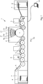
- FIG. 1 shows a sheet-processing ink printing machine 1 for the industrial production of single- or multi-color printed products in the inkjet printing process in carrying out a method according to the invention. Production takes place at a given print resolution, eg 1,200 x 1,200 dpi.
- the machine 1 comprises a stack feeder 2, a so-called precoating or pre-coating unit 3 for the application of a pre-coating, an inkjet printing unit 4 for the imagewise printing of the sheet, one or more dryer 5, a coating unit 6 and a stacking boom 7.
- the sheets 8 are transported by cylinders through the machine and are preferably made of paper, alternatively cardboard.
- the printing unit 4 comprises seven printing stations 4a to 4f arranged successively in the sheet transport direction for transferring ink drops, preferably the process colors K CMY OGV (black, cyan, magenta, yellow, orange, green and violet). Each station comprises a substantially transversely directed to the transport direction arrangement of print heads stationary in the printing operation, each with a plurality of individually controllable pressure nozzles for generating the drops ("drop on demand" or DOD).
- K CMY OGV black, cyan, magenta, yellow, orange, green and violet
- the stations 4a to 4f enable the page wide printing of a sheet side in the so-called single-pass operation, i. the pages of the sheets only reach the effective area of the stations once.
- the inks are water-based inks whose droplets react with the precoat to form dots of high dot sharpness and contain pigments as colorants.
- the driers 5 are preferably thermal dryers with infrared radiators, preferably LED radiators, and serve to evaporate the water from the printed ink, the precoat, the paint or from the printing substrate.
- the sheets 8 are guided in a direction 9a at a transport speed through the machine 1 and thereby printed.
- the machine 1 also comprises a machine control 14 with a computer and a control program running on the computer, wherein the computer can be part of a control desk (not shown). Also not shown are means for supplying the printing stations with inks and means for cleaning the printheads.
- FIG. 1 illustrated machine 1 can be operated according to the invention alternately in the 1st mode and in the 2nd mode.
- the change may be performed by the machine controller 14.
- FIG. 2a shows an embodiment of the invention, in this case a printed according to the invention section of two by four elements 13 of a Print image 12.
- the print image is produced by applying ink 10 in the form of drops 11 of a specific size to the printing material 8, in this case a paper sheet.
- ink 10 in the form of drops 11 of a specific size to the printing material 8, in this case a paper sheet.
- the elements 13 in the lines of the section shown are generated by adjacent nozzles of a print head (or a plurality of print heads for the different colors following one another in the transport direction 9a).
- Each element consists of one or more colors, ie of correspondingly colored ink drops 11, which produce correspondingly colored pressure points on the sheet 8.
- the pressure points can lie next to each other or overlap each other partially or completely.
- the elements 13 in the columns of the section shown are generated according to the timing of the printhead or the plurality of printheads. The same applies in turn to the FIGS. 2a . 3a to 3c in 4 ,
- FIG. 2a shows a section of a print image 12 generated in the first mode M1 of the inventive method:
- Each element or each grid point
- K CMY OGV the seven colors
- the (average) transport speed of the printing material achieved in the process will be referred to below as the normal speed.
- FIG. 2b shows similar to FIG. 2a a section of a color print printed in the first mode M1, but in this example only the four colors K CMY. Is printed, for example, on a machine 1 accordingly FIG. 1 but with only four printing stations 4a to 4d and at a normal speed achievable for this 4-color machine type.
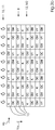
- FIGS. 3a to 3c and 4 show respective sections of printed images 12, which were printed in the second mode M2 of the method according to the invention.
- the print images 12 of the FIGS. 3a to 3c be in accordance with the print image in FIG. 2a on a seven-color printing press, the printed image of the FIG. 4 according to the printed image in FIG. 2b on a four-color press.
- FIG. 3a It can be seen that the transport speed compared to the embodiment of the FIG. 2a or quadrupled to the local normal speed, because lines with the same printing colors, for example black / K, repeat every four lines, ie between three additional lines are printed. Per unit time or according to the timing of the printheads thus a four times longer distance of the sheet is printed. For this purpose, the sheet is transported at substantially four times the transport speed. The same applies to the in the FIGS. 3b and 3c shown embodiments.
- the respective color reduced printed image 12 in the FIGS. 3b and 3c is a black or black and white or grayscale print image.
- the elements 13 of the respective print image 12 are either black / K or composed of OC, GM or YV.
- the latter three combination of complementary colors will ideally also give black or in reality a gray tone.
- F1, F2 and F3 which are used in the combinations F1 and C (F1C), F2 and M (F2M) as well as F3 and Y (F3Y) of the color black or the ideal grayscale come as close as possible and have as little color cast as possible. Instead of orange, for example, a red could be used more.
- FIGS. 3a to 3c A comparison of FIGS. 3a to 3c indicates that the printed image 12 is indeed constructed of the same elements 13, but that they are arranged differently in the embodiments, so form different "pattern".
- FIG. 3a indicates that the same elements 13 are arranged in the rows, ie the elements K, OC, GM and VY. Such "cross lines” could be perceptible to the eye and therefore disturbing.
- FIG. 3b makes it possible to recognize “diagonal lines”, which could also be perceptible.
- Figure 3c Finally, it can be seen that the elements 13 are arranged alternately in such a way that no continuous "lines” are perceived which is why this last embodiment is the preferred one. Alternatively, a statistical arrangement of the cells can be selected.
- the preferred embodiment in Figure 3c indicates that the black elements 13 with the coming to lie between them colorful cells "on average", z. B. in a field of 4 times 8 elements (4 lateral, 8 longitudinal to the transport direction), a gray value.
- the rastering and / or the droplet size are adjusted in a known manner at the relevant location.
- FIG. 4 It can be seen that the transport speed compared to the embodiment of the FIG. 2b or doubled to the normal speed there: One line is printed with black K, the next line with CMY and so on. Also, the printed image 12 produced in this embodiment is color-reduced, in particular black or black-and-white or a grayscale printed image.
- the drop sizes 11 are in the embodiments of FIGS. 3a to 3c and 4 differently, in particular chosen larger than in the embodiments of FIGS. 2a and 2b or in the second mode M2 differently than in the first mode M1. As in the embodiment of the FIG. 4 If only 3 colors are mixed to black or gray, the color density achievable with a small droplet size can be too low, which is why in this case it may be advisable to print larger droplets.
Landscapes
- Engineering & Computer Science (AREA)
- Theoretical Computer Science (AREA)
- Quality & Reliability (AREA)
- Human Computer Interaction (AREA)
- Physics & Mathematics (AREA)
- General Engineering & Computer Science (AREA)
- General Physics & Mathematics (AREA)
- Ink Jet (AREA)
Abstract
Description
- Die Erfindung betrifft ein Verfahren mit den Merkmalen des Oberbegriffs von Anspruch 1.
- Die Erfindung liegt auf dem technischen Gebiet der grafischen Industrie und dort insbesondere im Bereich des industriellen Tintendrucks (InkJet) auf flache Substrate, d.h. des Auftragens von flüssiger Tinte auf bogen- oder bahnförmige Bedruckstoffe, bevorzugt aus Papier, Karton, Pappe oder Kunststoff.
- Eine unter dem Produktnamen "Primefire" bekannte und von der Heidelberger Druckmaschinen AG, Deutschland, entwickelte Tintendruckmaschine für die industrielle Produktion bedruckt Papierbogen mit wasserbasierten Inkjet-Tinten. Die Maschine umfasst sieben aufeinander folgende Druckstationen, welche die Farben CMYK (Cyan, Magenta, Gelb und Schwarz) und OGV (Orange, Grün, Violett) mit Druckköpfen auf das Papier übertragen. Die aufgetragenen Tinten werden unter Einsatz von IR-Trocknern getrocknet.
- Die Druckgeschwindigkeit dieser Maschine und ähnlicher Maschinen ist im Normalbetrieb durch die Taktung der Druckköpfe begrenzt.
- Die
EP 373 957 - Die
JP 10-186768 A - Es ist daher eine Aufgabe der Erfindung, eine Verbesserung gegenüber dem Stand der Technik zu schaffen, welche es insbesondere ermöglicht, die Druckgeschwindigkeit und damit die pro Zeiteinheit produzierten Druckerzeugnisse einer Maschine - wenigstens für ausgewählte Druckaufträge - auf einfache Weise, insbesondere ohne Umrüstmaßnahmen hinsichtlich der Tintenversorgung oder der Druckköpfe, zu erhöhen.
- Diese Aufgabe wird erfindungsgemäß durch ein Verfahren nach Anspruch 1 gelöst. Vorteilhafte und daher bevorzugte Weiterbildungen der Erfindung ergeben sich aus den Unteransprüchen sowie aus der Beschreibung und den Zeichnungen.
- Die Erfindung betrifft ein Verfahren zum wechselweisen Betreiben einer Tinten-Druckmaschine, welche einen mit Transportgeschwindigkeit geförderten Bedruckstoff mit mehreren Tinten einem Druckbild entsprechend bedruckt, wobei zwischen den folgenden beiden Modi gewechselt wird:
- 1. Modus: Drucken eines n-farbigen ersten Druckauftrages bei einer ersten Transportgeschwindigkeit und bei einer Druckauflösung mit n Tinten, d.h. mit schwarzer Tinte und n-1 verschiedenen bunten Tinten; und
- 2. Modus: Drucken eines farbreduzierten zweiten Druckauftrages bei einer gegenüber der ersten erhöhten zweiten Transportgeschwindigkeit und bei unveränderter Druckauflösung mit den n Tinten.
- Die Erfindung ermöglicht in vorteilhafter Weise, die Druckgeschwindigkeit und damit die pro Zeiteinheit produzierten Druckerzeugnisse - wenigstens für ausgewählte und im 2. Modus gedruckte Druckaufträge - auf einfache Weise, insbesondere ohne Umrüstmaßnahmen hinsichtlich der Tintenversorgung oder der Druckköpfe, zu erhöhen.
- Die Erfindung ermöglicht es daher in vorteilhafter Weise, bevorzugt einfarbige (wie z.B. schwarze, schwarze-weiße bzw. s/w oder graustufige) Druckaufträge mit höherer Transportgeschwindigkeit des Bedruckstoffs und somit auch mit höherer Druckgeschwindigkeit abzuarbeiten. Die Druckauflösung wird trotz dieser Erhöhung nicht herabgesetzt, d.h. die Druckqualität bleibt unverändert.
- Mit anderen Worten: eine Mehrfarben-Druckmaschine kann erfindungsgemäß im 1. Modus als solche betrieben und hierzu im Wechsel, d.h. im 2. Modus, als z.B. schnellere 1-Farben-Druckmaschine werden. Je nach anstehendem Druckauftrag (Farbdruck oder nicht) wird ein Wechsel der Modi durchgeführt. Als Beispiel sei genannt: Modus 1 mit 3000 7-farbigen Drucken pro Stunde und Modus 2 mit 12000 s/w-Drucken pro Stunde.
- "Bedruckstoff" kann Folgendes umfassen: Papier, Karton, Pappe (auch Wellpappe) oder Kunststofffolie, jeweils bevorzugt als Bogen.
- Eine bevorzugte Weiterbildung der Erfindung kann sich dadurch auszeichnen, dass im 2. Modus ein Schwarzweiß- oder Graustufen-Druckauftrag gedruckt wird.
- Eine bevorzugte Weiterbildung der Erfindung kann sich dadurch auszeichnen, dass ein Anteil von schwarzen oder grauen Elementen des Druckbildes mit den n-1 verschiedenen bunten Tinten gedruckt wird. Die Elemente können zusammengesetzte Druckpunkte des Druckbildes sein.
- Eine bevorzugte Weiterbildung der Erfindung kann sich dadurch auszeichnen, dass n=7 ist, wobei die folgenden Tinten K CMY OGV verdruckt werden: Schwarz bzw. K, Cyan bzw. C, Magenta bzw. M, Gelb bzw. Y, Orange bzw. O, Grün bzw. G und Violett bzw. V. Schwarz oder Grau/Graustufen kann bevorzugt wie folgt zusammengesetzt werden: OC, GM oder VY.
- Anstelle von OGV kann auch eine andere Kombination von drei Farben verwendet werden: Bevorzugt solche Farben F1, F2 und F3, welche mit CMY zusammen jeweils Schwarz oder Grau bzw. Graustufen besser annähern als OGV: F1C, F2M F3Y.
- Eine bevorzugte Weiterbildung der Erfindung kann sich dadurch auszeichnen, dass im wesentlichen Dreiviertel der schwarzen oder grauen/graustufigen Elemente des Druckbildes mit den Tinten OC, GM oder VY (oder alternativ: F1C, F2M F3Y) gedruckt werden.
- Eine bevorzugte Weiterbildung der Erfindung kann sich dadurch auszeichnen, dass die zweite Transportgeschwindigkeit im Wesentlichen das Vierfache der ersten Transportgeschwindigkeit ist.
- Eine bevorzugte Weiterbildung der Erfindung kann sich dadurch auszeichnen, dass n=4 ist, wobei die folgenden Tinten K CMY verdruckt werden: Schwarz bzw. K, Cyan bzw. C, Magenta bzw. M und Gelb bzw. Y.
- Schwarz oder Grau/ Graustufen kann bevorzugt wie folgt zusammengesetzt werden: CMY.
- Eine bevorzugte Weiterbildung der Erfindung kann sich dadurch auszeichnen, dass im Wesentlichen die Hälfte der schwarzen oder grauen/graustufigen Elemente des Druckbildes mit den Tinten CMY gedruckt wird.
- Eine bevorzugte Weiterbildung der Erfindung kann sich dadurch auszeichnen, dass die zweite Transportgeschwindigkeit im Wesentlichen das Doppelte der ersten Transportgeschwindigkeit ist.
- Die Merkmale der Erfindung, der Weiterbildungen der Erfindung und der Ausführungsbeispiele zur Erfindung stellen auch in beliebiger Kombination miteinander vorteilhafte Weiterbildungen der Erfindung dar. Weiterbildungen der Erfindung können zudem die - im obigen Abschnitt "Technisches Gebiet der Erfindung" offenbarten - Einzelmerkmale oder Merkmalskombinationen aufweisen.
- Die Erfindung und deren bevorzugte Weiterbildungen werden nachfolgend unter Bezug auf die Zeichnungen anhand eines bevorzugten Ausführungsbeispiels näher beschrieben. Einander entsprechende Merkmale sind in den Figuren mit denselben Bezugszeichen versehen.
- Die Zeichnungen zeigen:
- Figur 1
- Eine Maschine bei der Durchführung eines erfindungsgemäßen Verfahrens;
- Figur 2a
- ein Ausschnitt eines siebenfarbigen Druckbildes gedruckt im 1. Modus;
- Figur 2b
- ein Ausschnitt eines vierfarbigen Druckbildes gedruckt im 1. Modus;
- Figur 3a
- ein Ausschnitt eines siebenfarbigen Druckbildes gedruckt im 2. Modus;
- Figur 3b
- ein Ausschnitt eines siebenfarbigen Druckbildes gedruckt im 2. Modus;
- Figur 3c
- ein Ausschnitt eines siebenfarbigen Druckbildes gedruckt im 2. Modus; und
- Figur 4
- ein Ausschnitt eines vierfarbigen Druckbildes gedruckt im 2. Modus.
- Die
Figur 1 zeigt eine bogenverarbeitende Tintendruckmaschine 1 für die industrielle Produktion ein- oder mehrfarbiger Druckprodukte im Inkjet-Druckverfahren bei der Durchführung eines erfindungsgemäßen Verfahrens. Die Produktion erfolgt bei vorgegebener Druckauflösung, z.B. 1.200 x 1.200 dpi. - Die Maschine 1 umfasst einen Stapel-Anleger 2, ein so genanntes Precoat- oder Vorbeschichtungswerk 3 für den Auftrag einer Vorbeschichtung, ein Inkjet-Druckwerk 4 für das bildgemäße Bedrucken der Bogen, einen oder mehrere Trockner 5, ein Lackwerk 6 und einen Stapel-Ausleger 7. Die Bogen 8 werden mit Zylindern durch die Maschine transportiert und bestehen bevorzugt aus Papier, alternativ aus Karton.
- Das Druckwerk 4 umfasst sieben in Bogen-Transportrichtung aufeinander folgend angeordnete Druckstationen 4a bis 4f zum Übertragen von Tintentropfen, bevorzugt der Prozess-Farben K CMY OGV (Schwarz, Cyan, Magenta, Gelb, Orange, Grün und Violett). Jede Station umfasst eine im Wesentlichen quer zur Transportrichtung ausgerichtete Anordnung von im Druckbetrieb unbewegten Druckköpfen mit je einer Vielzahl an einzeln ansteuerbaren Druckdüsen zum Erzeugen der Tropfen ("Drop on demand" bzw. DOD).
- Die Stationen 4a bis 4f ermöglichen das seitenbreite Bedrucken einer Bogenseite im so genannten single-pass-Betrieb, d.h. die Bogenseiten gelangen nur einmal in den Wirkbereich der Stationen. Die Tinten sind wasserbasierte Tinten, deren Tropfen mit der Vorbeschichtung reagieren um Druckpunkte hoher Punktschärfe zu bilden, und enthalten als Farbmittel Pigmente.
- Die Trockner 5 sind bevorzugt thermische Trockner mit Infrarot-Strahlern, bevorzugt LED-Strahlern, und dienen dem Verdampfen des Wassers aus der verdruckten Tinte, dem Precoat, dem Lack bzw. aus dem Bedruckstoff.
- Die Bogen 8 werden in einer Richtung 9a mit einer Transportgeschwindigkeit durch die Maschine 1 geführt und dabei bedruckt.
- Die Maschine 1 umfasst auch eine Maschinensteuerung 14 mit einem Rechner und einem auf dem Rechner laufenden Steuerprogramm, wobei der Rechner Teil eines nicht dargestellten Bedienpults sein kann. Ebenfalls nicht dargestellt sind eine Einrichtung zur Versorgung der Druckstationen mit Tinten und eine Einrichtung zur Reinigung der Druckköpfe.
- Die in
Figur 1 dargestellte Maschine 1 kann erfindungsgemäß wechselweise im 1. Modus und im 2. Modus betreiben werden. Der Wechsel kann von der Maschinensteuerung 14 ausgeführt werden. -
Figur 2a zeigt ein Ausführungsbeispiel der Erfindung, in diesem Fall einen erfindungsgemäß gedruckten Ausschnitt von zwei mal vier Elementen 13 eines Druckbildes 12. Das Druckbild wird durch Aufbringen von Tinte 10 in Form von Tropfen 11 bestimmter Größe auf den Bedruckstoff 8, in diesem Fall ein Papierbogen, erzeugt. Entsprechendes gilt für dieFiguren 2b ,3a bis 3c und4 . - Die Elemente 13 in den Zeilen des gezeigten Ausschnitts (also in lateraler Richtung 9b) werden von benachbarten Düsen eines Druckkopfs (oder mehrerer, in Transportrichtung 9a aufeinander folgender Druckköpfe für die verschiedenen Farben) erzeugt. Jedes Element besteht aus einer oder mehreren Farben, d. h. aus entsprechend farbigen Tintentropfen 11, welche entsprechend farbige Druckpunkte auf dem Bogen 8 erzeugen. Die Druckpunkte können dabei nebeneinander liegen oder einander teilweise oder komplett überlagern. Die Elemente 13 in den Spalten des gezeigten Ausschnitts (also in Transport-Richtung 9a) werden der Taktung des Druckkopfs oder der mehreren Druckköpfe entsprechend erzeugt. Entsprechendes gilt wiederum auch für die
Figuren 2a ,3a bis 3c in4 . -
Figur 2a zeigt einen Ausschnitt eines im ersten Modus M1 des erfindungsgemäßen Verfahrens erzeugten Druckbilds 12: Jedes Element (bzw. jeder Rasterpunkt) kann dabei aus mehreren Farben bzw. entsprechenden Tinten 10 zusammengesetzt sein, im gezeigten Beispiel sind es die sieben Farben K CMY OGV. Es wird also beispielhaft ein Siebenfarbendruck hergestellt. Die dabei erreichte (durchschnittliche) Transportgeschwindigkeit des Bedruckstoffs soll im Folgenden als Normalgeschwindigkeit bezeichnet werden. Gedruckt wird zum Beispiel auf der inFigur 1 gezeigten Maschine 1. -
Figur 2b zeigt ähnlich wieFigur 2a einen im ersten Modus M1 bedruckten Ausschnitt eines Farbdrucks, jedoch sind es in diesem Beispiel nur die vier Farben K CMY. Gedruckt wird zum Beispiel auf einer Maschine 1 entsprechendFigur 1 , jedoch mit nur vier Druckstationen 4a bis 4d und bei einer für diesen 4-Farb-Maschinentyp erreichbaren Normalgeschwindigkeit. - Die folgenden
Figuren 3a bis 3c und4 zeigen jeweils Ausschnitte von Druckbildern 12, die im zweiten Modus M2 des erfindungsgemäßen Verfahrens gedruckt wurden. Die Druckbilder 12 derFiguren 3a bis 3c werden entsprechend dem Druckbild inFigur 2a auf einer Siebenfarben-Druckmaschine gedruckt, das Druckbild derFigur 4 entsprechend dem Druckbild inFigur 2b auf einer Vierfarben-Druckmaschine. - In
Figur 3a ist erkennbar, dass die Transportgeschwindigkeit im Vergleich zur Ausführungsform derFigur 2a bzw. zur dortigen Normalgeschwindigkeit vervierfacht wurde, denn Zeilen mit gleichen Druckfarben, zum Beispiel Schwarz/K, wiederholen sich alle vier Zeilen, d. h. dazwischen werden drei weitere Zeilen gedruckt. Pro Zeiteinheit oder entsprechend der Taktung der Druckköpfe wird somit eine viermal längere Strecke des Bogens bedruckt. Hierzu wird der Bogen mit im Wesentlichen vierfacher Transportgeschwindigkeit transportiert. Entsprechendes gilt für die in denFiguren 3b und3c gezeigten Ausführungsformen. - Das jeweilige farbreduzierte Druckbild 12 in den
Figuren 3b und3c ist ein Schwarz oder Schwarz-Weiß oder Graustufen-Druckbild. Die Elemente 13 des jeweiligen Druckbildes 12 sind entweder Schwarz/K oder zusammengesetzt aus OC, GM oder YV. Letztere drei Kombination aus Komplementärfarben ergeben im Idealfall auch Schwarz oder in real einen Grauton. Es ist im Rahmen der Erfindung auch möglich und sogar von Vorteil, statt den Standard-Farben OGV solche spezielle angepassten Farben F1, F2 und F3 zu verwenden, welche in den Kombinationen F1 und C (F1C), F2 und M (F2M) sowie F3 und Y (F3Y) der Farbe Schwarz oder den idealen Graustufen möglichst nahe kommen und möglichst wenig Farbstich aufweisen. Statt Orange könnte z.B. eher ein Rot verwendet werden. - Ein Vergleich der
Figuren 3a bis 3c lässt erkennen, dass das Druckbild 12 zwar aus gleichen Elementen 13 aufgebaut ist, dass diese jedoch in den Ausführungsformen verschieden angeordnet sind, also unterschiedliche "Muster" bilden.Figur 3a lässt erkennen, dass in den Zeilen gleiche Elemente 13 angeordnet sind, also die Elemente K, OC, GM und VY. Solche "Quer-Linien" könnten mit dem Auge wahrnehmbar und daher störend sein.Figur 3b lässt entsprechend "Diagonal-Linien" erkennen, welche auch wahrnehmbar sein könnten. InFigur 3c ist schließlich erkennbar, dass die Elemente 13 derart abwechselnd angeordnet sind, dass keine durchgehenden "Linien" wahrgenommen werden können, weshalb diese letzte Ausführungsform die bevorzugte ist. Alternativ kann auch eine statistische Anordnung der Zellen gewählt werden. - Die bevorzugte Ausführungsform in
Figur 3c lässt erkennen, dass die schwarzen Elemente 13 mit den zwischen ihnen zu liegen kommenden bunt aufgebauten Zellen "im Mittel", z. B. in einem Feld von 4 mal 8 Elementen (4 lateral, 8 längs zur Transportrichtung), einen Grauwert ergeben. Um den entsprechend dem druckenden Druckbild 12 am jeweiligen Ort des Druckbildes zu erreichenden Grauwert tatsächlich zu erhalten, wird in bekannter Art und Weise am betreffenden Ort die Rasterung und/oder die Tropfengröße angepasst. - In
Figur 4 ist erkennbar, dass die Transportgeschwindigkeit im Vergleich zur Ausführungsform derFigur 2b bzw. zur dortigen Normalgeschwindigkeit verdoppelt wurde: Eine Zeile wird mit Schwarz K gedruckt, die nächste Zeile mit CMY und so weiter. Auch das in dieser Ausführungsform erzeugte Druckbild 12 ist farbreduziert, insbesondere Schwarz oder Schwarz-Weiß oder ein Graustufen-Druckbild. - Die Tropfengrößen 11 sind in den Ausführungsformen der
Figuren 3a bis 3c und4 anders, insbesondere größer gewählt als in den Ausführungsformen derFiguren 2a und 2b bzw. im zweiten Modus M2 anders als im ersten Modus M1. Da in der Ausführungsform derFigur 4 nur 3 Farben zu Schwarz oder Grau gemischt werden, kann die bei kleiner Tropfengröße erreichbare Farbdichte zu gering sein, weshalb es sich in diesem Fall anbieten kann, größere Tropfen zu drucken. -
- 1
- Tinten-Druckmaschine
- 2
- Anleger
- 3
- Vorbeschichtungswerk
- 4
- Druckwerk
- 4a-4f
- Druckstationen für K CMY OGV
- 5
- Trockner
- 6
- Lackwerk
- 7
- Ausleger
- 8
- Bogen aus Bedruckstoff
- 9a
- Transport-Richtung/Transportgeschwindigkeit
- 9b
- laterale Richtung
- 10
- Tinten
- 11
- Tintentropfen bzw. deren Größe
- 12
- Druckbild
- 13
- Elemente des Druckbildes
- 14
- Maschinensteuerung
- M1
- erster Modus
- M2
- zweiter Modus
Claims (9)
- Verfahren zum wechselweisen Betreiben einer Tinten-Druckmaschine (1), welche einen mit Transportgeschwindigkeit (9a) geförderten Bedruckstoff (8) mit mehreren Tinten (10) einem Druckbild (12) entsprechend bedruckt, wobei zwischen den folgenden beiden Modi (M1, M2) gewechselt wird:1. Modus (M1): Drucken eines n-farbigen ersten Druckauftrages bei einer ersten Transportgeschwindigkeit (9a) und bei einer Druckauflösung mit n Tinten (10), d.h. mit schwarzer Tinte und n-1 verschiedenen bunten Tinten; und2. Modus (M2): Drucken eines farbreduzierten zweiten Druckauftrages bei einer gegenüber der ersten erhöhten zweiten Transportgeschwindigkeit (9a) und bei unveränderter Druckauflösung mit den n Tinten (10).
- Verfahren nach Anspruch 1,
dadurch gekennzeichnet,
dass im 2. Modus ein Schwarzweiß- oder Graustufen-Druckauftrag gedruckt wird. - Verfahren nach Anspruch 2,
dadurch gekennzeichnet,
dass ein Anteil von schwarzen oder grauen Elementen des Druckbildes mit den n-1 verschiedenen bunten Tinten (10) gedruckt wird. - Verfahren nach Anspruch 3,
dadurch gekennzeichnet,
dass n=7 ist, wobei die folgenden Tinten (10) K CMY OGV verdruckt werden:Schwarz bzw. K, Cyan bzw. C, Magenta bzw. M, Gelb bzw. Y, Orange bzw. O, Grün bzw. G und Violett bzw. V. - Verfahren nach Anspruch 4,
dadurch gekennzeichnet,
dass Dreiviertel der schwarzen oder grauen Elemente des Druckbildes mit den Tinten (10) OC, GM oder VY gedruckt werden. - Verfahren nach Anspruch 5,
dadurch gekennzeichnet,
dass die zweite Transportgeschwindigkeit (9a) im Wesentlichen das Vierfache der ersten Transportgeschwindigkeit (9a) ist. - Verfahren nach Anspruch 3,
dadurch gekennzeichnet,
dass n=4 ist, wobei die folgenden Tinten K CMY verdruckt werden: Schwarz bzw. K, Cyan bzw. C, Magenta bzw. M und Gelb bzw. Y. - Verfahren nach Anspruch 7,
dadurch gekennzeichnet,
dass die Hälfte der schwarzen oder grauen Elemente des Druckbildes mit den Tinten CMY gedruckt wird. - Verfahren nach Anspruch 8,
dadurch gekennzeichnet,
dass die zweite Transportgeschwindigkeit (9a) im Wesentlichen das Doppelte der ersten Transportgeschwindigkeit (9a) ist.
Priority Applications (3)
| Application Number | Priority Date | Filing Date | Title |
|---|---|---|---|
| EP18157352.8A EP3527385B1 (de) | 2018-02-19 | 2018-02-19 | Verfahren zum wechselweisen betreiben einer tinten-druckmaschine |
| CN201910027038.0A CN110175003A (zh) | 2018-02-19 | 2019-01-11 | 用于将喷墨印刷机以变换的方式运行的方法 |
| US16/262,070 US10737505B2 (en) | 2018-02-19 | 2019-01-30 | Method for alternately operating an inkjet printing machine |
Applications Claiming Priority (1)
| Application Number | Priority Date | Filing Date | Title |
|---|---|---|---|
| EP18157352.8A EP3527385B1 (de) | 2018-02-19 | 2018-02-19 | Verfahren zum wechselweisen betreiben einer tinten-druckmaschine |
Publications (2)
| Publication Number | Publication Date |
|---|---|
| EP3527385A1 true EP3527385A1 (de) | 2019-08-21 |
| EP3527385B1 EP3527385B1 (de) | 2022-08-24 |
Family
ID=61244447
Family Applications (1)
| Application Number | Title | Priority Date | Filing Date |
|---|---|---|---|
| EP18157352.8A Active EP3527385B1 (de) | 2018-02-19 | 2018-02-19 | Verfahren zum wechselweisen betreiben einer tinten-druckmaschine |
Country Status (3)
| Country | Link |
|---|---|
| US (1) | US10737505B2 (de) |
| EP (1) | EP3527385B1 (de) |
| CN (1) | CN110175003A (de) |
Cited By (1)
| Publication number | Priority date | Publication date | Assignee | Title |
|---|---|---|---|---|
| EP4043193A1 (de) | 2021-02-15 | 2022-08-17 | Carl Zeiss Vision International GmbH | Verfahren zur herstellung eines brillenglases und verfahren zur steuerung von herstellungswerkzeugen zur herstellung von brillengläsern |
Families Citing this family (1)
| Publication number | Priority date | Publication date | Assignee | Title |
|---|---|---|---|---|
| JP2022123659A (ja) * | 2021-02-12 | 2022-08-24 | 株式会社リコー | 膜形成方法、及び膜形成装置 |
Citations (6)
| Publication number | Priority date | Publication date | Assignee | Title |
|---|---|---|---|---|
| JPH0226753A (ja) * | 1988-07-18 | 1990-01-29 | Canon Inc | カラープリンタ装置 |
| EP0373957A1 (de) | 1988-12-15 | 1990-06-20 | Xerox Corporation | Tintenstrahlmarkierungskopf mit der Fähigkeit zum mehrfarbigen Markieren |
| JP2652405B2 (ja) * | 1988-04-26 | 1997-09-10 | キヤノン株式会社 | インクジェット記録装置 |
| JPH10186768A (ja) | 1996-12-26 | 1998-07-14 | Minolta Co Ltd | 画像形成装置 |
| JPH10291329A (ja) * | 1997-02-24 | 1998-11-04 | Oki Data:Kk | 記録装置 |
| US20090058910A1 (en) * | 2007-09-04 | 2009-03-05 | Shinichi Hatanaka | Image Forming Method, Image Forming Apparatus, and Image Forming Program and Recording Medium |
Family Cites Families (6)
| Publication number | Priority date | Publication date | Assignee | Title |
|---|---|---|---|---|
| IT1195151B (it) | 1986-09-05 | 1988-10-12 | Olivetti & Co Spa | Apparecchiatura per ripristinare il funzionamento degli ugelli di una testina di stampa a getto d inchiostro e relativo procedimento |
| US6367912B1 (en) * | 1997-02-24 | 2002-04-09 | Oki Data Corporation | Ink jet recording apparatus |
| JP2007030198A (ja) * | 2005-07-22 | 2007-02-08 | Ricoh Co Ltd | 画像形成方法、画像形成方法を実行するためのプログラム及びインクジェット記録装置 |
| US7401877B2 (en) * | 2006-09-22 | 2008-07-22 | Xerox Corporation | Printing mode for a printer |
| US8936357B2 (en) * | 2008-06-30 | 2015-01-20 | Eastman Kodak Company | Inkjet printer with inks containing polyoxygenated-polyols |
| JP2010186768A (ja) | 2009-02-10 | 2010-08-26 | Brother Ind Ltd | 有機半導体素子、及びその製造方法 |
-
2018
- 2018-02-19 EP EP18157352.8A patent/EP3527385B1/de active Active
-
2019
- 2019-01-11 CN CN201910027038.0A patent/CN110175003A/zh active Pending
- 2019-01-30 US US16/262,070 patent/US10737505B2/en active Active
Patent Citations (6)
| Publication number | Priority date | Publication date | Assignee | Title |
|---|---|---|---|---|
| JP2652405B2 (ja) * | 1988-04-26 | 1997-09-10 | キヤノン株式会社 | インクジェット記録装置 |
| JPH0226753A (ja) * | 1988-07-18 | 1990-01-29 | Canon Inc | カラープリンタ装置 |
| EP0373957A1 (de) | 1988-12-15 | 1990-06-20 | Xerox Corporation | Tintenstrahlmarkierungskopf mit der Fähigkeit zum mehrfarbigen Markieren |
| JPH10186768A (ja) | 1996-12-26 | 1998-07-14 | Minolta Co Ltd | 画像形成装置 |
| JPH10291329A (ja) * | 1997-02-24 | 1998-11-04 | Oki Data:Kk | 記録装置 |
| US20090058910A1 (en) * | 2007-09-04 | 2009-03-05 | Shinichi Hatanaka | Image Forming Method, Image Forming Apparatus, and Image Forming Program and Recording Medium |
Cited By (2)
| Publication number | Priority date | Publication date | Assignee | Title |
|---|---|---|---|---|
| EP4043193A1 (de) | 2021-02-15 | 2022-08-17 | Carl Zeiss Vision International GmbH | Verfahren zur herstellung eines brillenglases und verfahren zur steuerung von herstellungswerkzeugen zur herstellung von brillengläsern |
| WO2022171882A1 (en) | 2021-02-15 | 2022-08-18 | Carl Zeiss Vision International Gmbh | Method of manufacturing a spectacle lens and method of controlling manufacturing tools for manufacturing spectacle lenses |
Also Published As
| Publication number | Publication date |
|---|---|
| CN110175003A (zh) | 2019-08-27 |
| US10737505B2 (en) | 2020-08-11 |
| EP3527385B1 (de) | 2022-08-24 |
| US20190255857A1 (en) | 2019-08-22 |
Similar Documents
| Publication | Publication Date | Title |
|---|---|---|
| AT500106B1 (de) | Tintenstrahldruckvorrichtung | |
| DE3615604C2 (de) | ||
| KR101518087B1 (ko) | 프린팅 방법 | |
| EP3431291B1 (de) | Druckmaschine mit einer mehrzahl von in reihe angeordneten flexodruckwerken und verfahren zum betreiben einer solchen druckmaschine | |
| DE102006016065A1 (de) | Zusatzeinrichtung für eine nach dem Offset-Druckprinzip arbeitenden Druckmaschine | |
| DE69809002T2 (de) | Druckverfahren mit Tintenstrahdrucker mit verbesserter horizontalen Auflösung | |
| DE102016203917A1 (de) | Verfahren zur Kompensation ausgefallener Druckdüsen in einer Inkjet-Druckmaschine | |
| DE102017205280A1 (de) | Verfahren zum Einrichten und Betreiben einer Tintendruckmaschine für einen Druckauftrag | |
| DE10219142B4 (de) | Bildausgabevorrichtung zum Verbessern einer Bildauflösung und eines Farbtonausdrucks | |
| EP3527385B1 (de) | Verfahren zum wechselweisen betreiben einer tinten-druckmaschine | |
| EP3318410B1 (de) | Verfahren zum betreiben einer mehrfarben-tintendruckmaschine | |
| DE102016109025A1 (de) | Verfahren und Steuereinheit zur Druckqualitätsverbesserung eines Tintenstrahl-Drucksystems | |
| EP4045322B1 (de) | Intaglio-tiefdruckmaschine und verfahren zum aufbringen von zumindest einem druckfluid auf zumindest ein substrat | |
| DE102016210069A1 (de) | Verfahren zur Bewertung der Relevanz ausgefallener Druckdüsen in Inkjet-Drucksystemen | |
| DE102017211456B3 (de) | Verfahren zum Bedrucken von saugfähigem Bedruckstoff mit Tinten und Feuchtmittel | |
| EP0548097B1 (de) | Verfahren zum reduzieren der mittels tintenschreibeinrichtungen auf aufzeichnungsträger aufgebrachten tintenmenge | |
| EP3086945B1 (de) | Tintenstrahldrucker sowie verfahren zum betrieb eines tintenstrahldruckers | |
| DE60125503T2 (de) | Tintenstrahldrucker mit relativ zueinander beweglichen Düsenreihen | |
| DE102016121497A1 (de) | Tintenstrahldrucksystem zur Reduzierung von systembedingter Streifigkeit und ein entsprechendes Verfahren | |
| DE102024113523B3 (de) | Druckeinheit sowie Verfahren zum Bedrucken eines Substrats | |
| DE60210208T2 (de) | Druckverfahren und -vorrichtung zum Austauschen defekter Druckelemente | |
| EP2388136B1 (de) | Kombinationsdruckwerk | |
| EP3686803B1 (de) | Verfahren zum erzeugen eines druckproduktes mit mindestens einem non-impact-druckaggregat und druckprodukt | |
| DE102013226653B4 (de) | Verfahren zum Drucken zumindest eines Druckbilds mittels zumindest einer als Rollen-Druckmaschine ausgebildeten Druckmaschine | |
| DE102015104574B3 (de) | Verfahren zur Optimierung der Rasterpunktpositionierung im Digitaldruck |
Legal Events
| Date | Code | Title | Description |
|---|---|---|---|
| PUAI | Public reference made under article 153(3) epc to a published international application that has entered the european phase |
Free format text: ORIGINAL CODE: 0009012 |
|
| STAA | Information on the status of an ep patent application or granted ep patent |
Free format text: STATUS: THE APPLICATION HAS BEEN PUBLISHED |
|
| AK | Designated contracting states |
Kind code of ref document: A1 Designated state(s): AL AT BE BG CH CY CZ DE DK EE ES FI FR GB GR HR HU IE IS IT LI LT LU LV MC MK MT NL NO PL PT RO RS SE SI SK SM TR |
|
| AX | Request for extension of the european patent |
Extension state: BA ME |
|
| STAA | Information on the status of an ep patent application or granted ep patent |
Free format text: STATUS: REQUEST FOR EXAMINATION WAS MADE |
|
| 17P | Request for examination filed |
Effective date: 20200221 |
|
| RBV | Designated contracting states (corrected) |
Designated state(s): AL AT BE BG CH CY CZ DE DK EE ES FI FR GB GR HR HU IE IS IT LI LT LU LV MC MK MT NL NO PL PT RO RS SE SI SK SM TR |
|
| GRAP | Despatch of communication of intention to grant a patent |
Free format text: ORIGINAL CODE: EPIDOSNIGR1 |
|
| STAA | Information on the status of an ep patent application or granted ep patent |
Free format text: STATUS: GRANT OF PATENT IS INTENDED |
|
| INTG | Intention to grant announced |
Effective date: 20220425 |
|
| GRAS | Grant fee paid |
Free format text: ORIGINAL CODE: EPIDOSNIGR3 |
|
| GRAA | (expected) grant |
Free format text: ORIGINAL CODE: 0009210 |
|
| STAA | Information on the status of an ep patent application or granted ep patent |
Free format text: STATUS: THE PATENT HAS BEEN GRANTED |
|
| AK | Designated contracting states |
Kind code of ref document: B1 Designated state(s): AL AT BE BG CH CY CZ DE DK EE ES FI FR GB GR HR HU IE IS IT LI LT LU LV MC MK MT NL NO PL PT RO RS SE SI SK SM TR |
|
| REG | Reference to a national code |
Ref country code: CH Ref legal event code: EP |
|
| REG | Reference to a national code |
Ref country code: DE Ref legal event code: R096 Ref document number: 502018010449 Country of ref document: DE |
|
| REG | Reference to a national code |
Ref country code: IE Ref legal event code: FG4D Free format text: LANGUAGE OF EP DOCUMENT: GERMAN |
|
| REG | Reference to a national code |
Ref country code: AT Ref legal event code: REF Ref document number: 1513385 Country of ref document: AT Kind code of ref document: T Effective date: 20220915 |
|
| REG | Reference to a national code |
Ref country code: LT Ref legal event code: MG9D |
|
| REG | Reference to a national code |
Ref country code: NL Ref legal event code: MP Effective date: 20220824 |
|
| PG25 | Lapsed in a contracting state [announced via postgrant information from national office to epo] |
Ref country code: SE Free format text: LAPSE BECAUSE OF FAILURE TO SUBMIT A TRANSLATION OF THE DESCRIPTION OR TO PAY THE FEE WITHIN THE PRESCRIBED TIME-LIMIT Effective date: 20220824 Ref country code: RS Free format text: LAPSE BECAUSE OF FAILURE TO SUBMIT A TRANSLATION OF THE DESCRIPTION OR TO PAY THE FEE WITHIN THE PRESCRIBED TIME-LIMIT Effective date: 20220824 Ref country code: PT Free format text: LAPSE BECAUSE OF FAILURE TO SUBMIT A TRANSLATION OF THE DESCRIPTION OR TO PAY THE FEE WITHIN THE PRESCRIBED TIME-LIMIT Effective date: 20221226 Ref country code: NO Free format text: LAPSE BECAUSE OF FAILURE TO SUBMIT A TRANSLATION OF THE DESCRIPTION OR TO PAY THE FEE WITHIN THE PRESCRIBED TIME-LIMIT Effective date: 20221124 Ref country code: NL Free format text: LAPSE BECAUSE OF FAILURE TO SUBMIT A TRANSLATION OF THE DESCRIPTION OR TO PAY THE FEE WITHIN THE PRESCRIBED TIME-LIMIT Effective date: 20220824 Ref country code: LV Free format text: LAPSE BECAUSE OF FAILURE TO SUBMIT A TRANSLATION OF THE DESCRIPTION OR TO PAY THE FEE WITHIN THE PRESCRIBED TIME-LIMIT Effective date: 20220824 Ref country code: LT Free format text: LAPSE BECAUSE OF FAILURE TO SUBMIT A TRANSLATION OF THE DESCRIPTION OR TO PAY THE FEE WITHIN THE PRESCRIBED TIME-LIMIT Effective date: 20220824 Ref country code: FI Free format text: LAPSE BECAUSE OF FAILURE TO SUBMIT A TRANSLATION OF THE DESCRIPTION OR TO PAY THE FEE WITHIN THE PRESCRIBED TIME-LIMIT Effective date: 20220824 |
|
| PG25 | Lapsed in a contracting state [announced via postgrant information from national office to epo] |
Ref country code: PL Free format text: LAPSE BECAUSE OF FAILURE TO SUBMIT A TRANSLATION OF THE DESCRIPTION OR TO PAY THE FEE WITHIN THE PRESCRIBED TIME-LIMIT Effective date: 20220824 Ref country code: IS Free format text: LAPSE BECAUSE OF FAILURE TO SUBMIT A TRANSLATION OF THE DESCRIPTION OR TO PAY THE FEE WITHIN THE PRESCRIBED TIME-LIMIT Effective date: 20221224 Ref country code: HR Free format text: LAPSE BECAUSE OF FAILURE TO SUBMIT A TRANSLATION OF THE DESCRIPTION OR TO PAY THE FEE WITHIN THE PRESCRIBED TIME-LIMIT Effective date: 20220824 Ref country code: GR Free format text: LAPSE BECAUSE OF FAILURE TO SUBMIT A TRANSLATION OF THE DESCRIPTION OR TO PAY THE FEE WITHIN THE PRESCRIBED TIME-LIMIT Effective date: 20221125 |
|
| PG25 | Lapsed in a contracting state [announced via postgrant information from national office to epo] |
Ref country code: SM Free format text: LAPSE BECAUSE OF FAILURE TO SUBMIT A TRANSLATION OF THE DESCRIPTION OR TO PAY THE FEE WITHIN THE PRESCRIBED TIME-LIMIT Effective date: 20220824 Ref country code: RO Free format text: LAPSE BECAUSE OF FAILURE TO SUBMIT A TRANSLATION OF THE DESCRIPTION OR TO PAY THE FEE WITHIN THE PRESCRIBED TIME-LIMIT Effective date: 20220824 Ref country code: ES Free format text: LAPSE BECAUSE OF FAILURE TO SUBMIT A TRANSLATION OF THE DESCRIPTION OR TO PAY THE FEE WITHIN THE PRESCRIBED TIME-LIMIT Effective date: 20220824 Ref country code: DK Free format text: LAPSE BECAUSE OF FAILURE TO SUBMIT A TRANSLATION OF THE DESCRIPTION OR TO PAY THE FEE WITHIN THE PRESCRIBED TIME-LIMIT Effective date: 20220824 Ref country code: CZ Free format text: LAPSE BECAUSE OF FAILURE TO SUBMIT A TRANSLATION OF THE DESCRIPTION OR TO PAY THE FEE WITHIN THE PRESCRIBED TIME-LIMIT Effective date: 20220824 |
|
| REG | Reference to a national code |
Ref country code: DE Ref legal event code: R097 Ref document number: 502018010449 Country of ref document: DE |
|
| PG25 | Lapsed in a contracting state [announced via postgrant information from national office to epo] |
Ref country code: SK Free format text: LAPSE BECAUSE OF FAILURE TO SUBMIT A TRANSLATION OF THE DESCRIPTION OR TO PAY THE FEE WITHIN THE PRESCRIBED TIME-LIMIT Effective date: 20220824 Ref country code: EE Free format text: LAPSE BECAUSE OF FAILURE TO SUBMIT A TRANSLATION OF THE DESCRIPTION OR TO PAY THE FEE WITHIN THE PRESCRIBED TIME-LIMIT Effective date: 20220824 |
|
| P01 | Opt-out of the competence of the unified patent court (upc) registered |
Effective date: 20230502 |
|
| PG25 | Lapsed in a contracting state [announced via postgrant information from national office to epo] |
Ref country code: AL Free format text: LAPSE BECAUSE OF FAILURE TO SUBMIT A TRANSLATION OF THE DESCRIPTION OR TO PAY THE FEE WITHIN THE PRESCRIBED TIME-LIMIT Effective date: 20220824 |
|
| PLBE | No opposition filed within time limit |
Free format text: ORIGINAL CODE: 0009261 |
|
| STAA | Information on the status of an ep patent application or granted ep patent |
Free format text: STATUS: NO OPPOSITION FILED WITHIN TIME LIMIT |
|
| 26N | No opposition filed |
Effective date: 20230525 |
|
| PG25 | Lapsed in a contracting state [announced via postgrant information from national office to epo] |
Ref country code: SI Free format text: LAPSE BECAUSE OF FAILURE TO SUBMIT A TRANSLATION OF THE DESCRIPTION OR TO PAY THE FEE WITHIN THE PRESCRIBED TIME-LIMIT Effective date: 20220824 |
|
| PG25 | Lapsed in a contracting state [announced via postgrant information from national office to epo] |
Ref country code: MC Free format text: LAPSE BECAUSE OF FAILURE TO SUBMIT A TRANSLATION OF THE DESCRIPTION OR TO PAY THE FEE WITHIN THE PRESCRIBED TIME-LIMIT Effective date: 20220824 |
|
| REG | Reference to a national code |
Ref country code: CH Ref legal event code: PL |
|
| REG | Reference to a national code |
Ref country code: BE Ref legal event code: MM Effective date: 20230228 |
|
| PG25 | Lapsed in a contracting state [announced via postgrant information from national office to epo] |
Ref country code: LU Free format text: LAPSE BECAUSE OF NON-PAYMENT OF DUE FEES Effective date: 20230219 Ref country code: LI Free format text: LAPSE BECAUSE OF NON-PAYMENT OF DUE FEES Effective date: 20230228 Ref country code: CH Free format text: LAPSE BECAUSE OF NON-PAYMENT OF DUE FEES Effective date: 20230228 |
|
| REG | Reference to a national code |
Ref country code: IE Ref legal event code: MM4A |
|
| PG25 | Lapsed in a contracting state [announced via postgrant information from national office to epo] |
Ref country code: IE Free format text: LAPSE BECAUSE OF NON-PAYMENT OF DUE FEES Effective date: 20230219 |
|
| PG25 | Lapsed in a contracting state [announced via postgrant information from national office to epo] |
Ref country code: BE Free format text: LAPSE BECAUSE OF NON-PAYMENT OF DUE FEES Effective date: 20230228 |
|
| REG | Reference to a national code |
Ref country code: AT Ref legal event code: MM01 Ref document number: 1513385 Country of ref document: AT Kind code of ref document: T Effective date: 20230219 |
|
| PG25 | Lapsed in a contracting state [announced via postgrant information from national office to epo] |
Ref country code: AT Free format text: LAPSE BECAUSE OF NON-PAYMENT OF DUE FEES Effective date: 20230219 |
|
| PG25 | Lapsed in a contracting state [announced via postgrant information from national office to epo] |
Ref country code: AT Free format text: LAPSE BECAUSE OF NON-PAYMENT OF DUE FEES Effective date: 20230219 |
|
| PG25 | Lapsed in a contracting state [announced via postgrant information from national office to epo] |
Ref country code: IT Free format text: LAPSE BECAUSE OF FAILURE TO SUBMIT A TRANSLATION OF THE DESCRIPTION OR TO PAY THE FEE WITHIN THE PRESCRIBED TIME-LIMIT Effective date: 20220824 |
|
| PG25 | Lapsed in a contracting state [announced via postgrant information from national office to epo] |
Ref country code: BG Free format text: LAPSE BECAUSE OF FAILURE TO SUBMIT A TRANSLATION OF THE DESCRIPTION OR TO PAY THE FEE WITHIN THE PRESCRIBED TIME-LIMIT Effective date: 20220824 |
|
| PG25 | Lapsed in a contracting state [announced via postgrant information from national office to epo] |
Ref country code: BG Free format text: LAPSE BECAUSE OF FAILURE TO SUBMIT A TRANSLATION OF THE DESCRIPTION OR TO PAY THE FEE WITHIN THE PRESCRIBED TIME-LIMIT Effective date: 20220824 |
|
| PG25 | Lapsed in a contracting state [announced via postgrant information from national office to epo] |
Ref country code: CY Free format text: LAPSE BECAUSE OF FAILURE TO SUBMIT A TRANSLATION OF THE DESCRIPTION OR TO PAY THE FEE WITHIN THE PRESCRIBED TIME-LIMIT; INVALID AB INITIO Effective date: 20180219 |
|
| PG25 | Lapsed in a contracting state [announced via postgrant information from national office to epo] |
Ref country code: HU Free format text: LAPSE BECAUSE OF FAILURE TO SUBMIT A TRANSLATION OF THE DESCRIPTION OR TO PAY THE FEE WITHIN THE PRESCRIBED TIME-LIMIT; INVALID AB INITIO Effective date: 20180219 |
|
| PG25 | Lapsed in a contracting state [announced via postgrant information from national office to epo] |
Ref country code: TR Free format text: LAPSE BECAUSE OF FAILURE TO SUBMIT A TRANSLATION OF THE DESCRIPTION OR TO PAY THE FEE WITHIN THE PRESCRIBED TIME-LIMIT Effective date: 20220824 |
|
| PGFP | Annual fee paid to national office [announced via postgrant information from national office to epo] |
Ref country code: GB Payment date: 20260226 Year of fee payment: 9 |
|
| PGFP | Annual fee paid to national office [announced via postgrant information from national office to epo] |
Ref country code: DE Payment date: 20260228 Year of fee payment: 9 |
|
| PGFP | Annual fee paid to national office [announced via postgrant information from national office to epo] |
Ref country code: FR Payment date: 20260225 Year of fee payment: 9 |