EP3527260B1 - Semiconductor laser module for application in noninvasive medical treatment - Google Patents
Semiconductor laser module for application in noninvasive medical treatment Download PDFInfo
- Publication number
- EP3527260B1 EP3527260B1 EP17863036.4A EP17863036A EP3527260B1 EP 3527260 B1 EP3527260 B1 EP 3527260B1 EP 17863036 A EP17863036 A EP 17863036A EP 3527260 B1 EP3527260 B1 EP 3527260B1
- Authority
- EP
- European Patent Office
- Prior art keywords
- semiconductor laser
- cooling
- reflection component
- light reflection
- disposed
- Prior art date
- Legal status (The legal status is an assumption and is not a legal conclusion. Google has not performed a legal analysis and makes no representation as to the accuracy of the status listed.)
- Active
Links
Images


Classifications
-
- A—HUMAN NECESSITIES
- A61—MEDICAL OR VETERINARY SCIENCE; HYGIENE
- A61B—DIAGNOSIS; SURGERY; IDENTIFICATION
- A61B18/00—Surgical instruments, devices or methods for transferring non-mechanical forms of energy to or from the body
- A61B18/18—Surgical instruments, devices or methods for transferring non-mechanical forms of energy to or from the body by applying electromagnetic radiation, e.g. microwaves
- A61B18/20—Surgical instruments, devices or methods for transferring non-mechanical forms of energy to or from the body by applying electromagnetic radiation, e.g. microwaves using laser
- A61B18/203—Surgical instruments, devices or methods for transferring non-mechanical forms of energy to or from the body by applying electromagnetic radiation, e.g. microwaves using laser applying laser energy to the outside of the body
-
- A—HUMAN NECESSITIES
- A61—MEDICAL OR VETERINARY SCIENCE; HYGIENE
- A61N—ELECTROTHERAPY; MAGNETOTHERAPY; RADIATION THERAPY; ULTRASOUND THERAPY
- A61N5/00—Radiation therapy
- A61N5/06—Radiation therapy using light
-
- A—HUMAN NECESSITIES
- A61—MEDICAL OR VETERINARY SCIENCE; HYGIENE
- A61N—ELECTROTHERAPY; MAGNETOTHERAPY; RADIATION THERAPY; ULTRASOUND THERAPY
- A61N5/00—Radiation therapy
- A61N5/06—Radiation therapy using light
- A61N5/0613—Apparatus adapted for a specific treatment
- A61N5/0616—Skin treatment other than tanning
-
- A—HUMAN NECESSITIES
- A61—MEDICAL OR VETERINARY SCIENCE; HYGIENE
- A61N—ELECTROTHERAPY; MAGNETOTHERAPY; RADIATION THERAPY; ULTRASOUND THERAPY
- A61N5/00—Radiation therapy
- A61N5/06—Radiation therapy using light
- A61N5/067—Radiation therapy using light using laser light
-
- A—HUMAN NECESSITIES
- A61—MEDICAL OR VETERINARY SCIENCE; HYGIENE
- A61B—DIAGNOSIS; SURGERY; IDENTIFICATION
- A61B18/00—Surgical instruments, devices or methods for transferring non-mechanical forms of energy to or from the body
- A61B2018/00005—Cooling or heating of the probe or tissue immediately surrounding the probe
- A61B2018/00047—Cooling or heating of the probe or tissue immediately surrounding the probe using Peltier effect
-
- A—HUMAN NECESSITIES
- A61—MEDICAL OR VETERINARY SCIENCE; HYGIENE
- A61B—DIAGNOSIS; SURGERY; IDENTIFICATION
- A61B18/00—Surgical instruments, devices or methods for transferring non-mechanical forms of energy to or from the body
- A61B2018/00315—Surgical instruments, devices or methods for transferring non-mechanical forms of energy to or from the body for treatment of particular body parts
- A61B2018/00452—Skin
- A61B2018/00458—Deeper parts of the skin, e.g. treatment of vascular disorders or port wine stains
- A61B2018/00464—Subcutaneous fat, e.g. liposuction, lipolysis
-
- A—HUMAN NECESSITIES
- A61—MEDICAL OR VETERINARY SCIENCE; HYGIENE
- A61B—DIAGNOSIS; SURGERY; IDENTIFICATION
- A61B18/00—Surgical instruments, devices or methods for transferring non-mechanical forms of energy to or from the body
- A61B2018/00636—Sensing and controlling the application of energy
- A61B2018/00642—Sensing and controlling the application of energy with feedback, i.e. closed loop control
-
- A—HUMAN NECESSITIES
- A61—MEDICAL OR VETERINARY SCIENCE; HYGIENE
- A61B—DIAGNOSIS; SURGERY; IDENTIFICATION
- A61B18/00—Surgical instruments, devices or methods for transferring non-mechanical forms of energy to or from the body
- A61B2018/00636—Sensing and controlling the application of energy
- A61B2018/00773—Sensed parameters
- A61B2018/00791—Temperature
-
- A—HUMAN NECESSITIES
- A61—MEDICAL OR VETERINARY SCIENCE; HYGIENE
- A61B—DIAGNOSIS; SURGERY; IDENTIFICATION
- A61B18/00—Surgical instruments, devices or methods for transferring non-mechanical forms of energy to or from the body
- A61B18/18—Surgical instruments, devices or methods for transferring non-mechanical forms of energy to or from the body by applying electromagnetic radiation, e.g. microwaves
- A61B18/20—Surgical instruments, devices or methods for transferring non-mechanical forms of energy to or from the body by applying electromagnetic radiation, e.g. microwaves using laser
- A61B2018/2035—Beam shaping or redirecting; Optical components therefor
- A61B2018/20553—Beam shaping or redirecting; Optical components therefor with special lens or reflector arrangement
-
- A—HUMAN NECESSITIES
- A61—MEDICAL OR VETERINARY SCIENCE; HYGIENE
- A61N—ELECTROTHERAPY; MAGNETOTHERAPY; RADIATION THERAPY; ULTRASOUND THERAPY
- A61N5/00—Radiation therapy
- A61N2005/002—Cooling systems
- A61N2005/005—Cooling systems for cooling the radiator
-
- A—HUMAN NECESSITIES
- A61—MEDICAL OR VETERINARY SCIENCE; HYGIENE
- A61N—ELECTROTHERAPY; MAGNETOTHERAPY; RADIATION THERAPY; ULTRASOUND THERAPY
- A61N5/00—Radiation therapy
- A61N5/06—Radiation therapy using light
- A61N2005/0664—Details
- A61N2005/0665—Reflectors
Definitions
- the disclosure herein relates to the field of semiconductor lasers, particularly relates to a semiconductor laser module and a method for application in noninvasive medical treatment.
- Documents WO 2016/074300 A1 , US 2015/289934 A1 and CN 203 423 371 U disclose different types of laser modules for medical treatment.
- a semiconductor laser has the characteristics: small size, light weight, long service life, and wide wavelength coverage. It is particularly suitable for medical beauty equipment.
- the application of the semiconductor laser in the area of medical beauty treatment mainly comprises removing hair, tendering skin, dissolving fat, etc.
- the dissolving fat scheme in the prior art mainly comprises the following three schemes:
- the main purpose of the present discloure is to provide a semiconductor laser module and a method.
- the characteristics of the scheme is: based on a direct-output type semiconductor laser, using the technical scheme provided by the present disclosure, the purpose of treatment can be achieved by extracorporeal irradiation without causing any trauma on the human body; also, the cost is low and the treatment effect is good.
- an embodiment of the present disclosure provides a semiconductor laser module.
- the semiconductor laser module comprises: a direct-output type semiconductor laser light source, and a light beam shaping device disposed in the light-exit direction of the direct-output type semiconductor laser light source.
- the light beam shaping device comprises a light reflection component configured to homogenize the laser beam outputted by the direct-output type semiconductor laser light source.
- the light beam shaping device also comprises a lens.
- the lens is disposed between the direct-output type semiconductor laser light source and the light reflection component, and is used to carry out fast-axis and/or slow-axis beam expansion for the laser beam outputted by the direct-output type semiconductor laser light source.
- the light reflection component is a hollow component.
- the matrix material for the light reflection component comprises metal or plastic.
- the inner wall of the light reflection component is configured to achieve that the laser beam is reflected on the inner wall of the light reflection component, to form a uniform light path.
- a reflecting medium is plated on the inner wall of the light reflection component.
- the reflecting medium comprises metal.
- the cross section of the light reflection component is square, or circular, or polygonal.
- the cross-sectional area of the laser beam input end of the light reflection component is smaller than or equal to the cross-sectional area of the laser beam output end.
- the number of the lenses is one or more.
- the light reflection component is a reflecting bowl or a reflecting cover.
- the module also comprises a cooling structure.
- the cooling structure is disposed on the periphery of the light reflection component.
- the cooling structure comprises a cooling frame, a thermoelectric cooler and a heat dissipation block.
- the heat dissipation block is disposed on the periphery of the light reflection component.
- the heat dissipation block is configured to cool the light reflection component and the thermoelectric cooler.
- the thermoelectric cooler is configured to cool the cooling frame.
- the cooling frame is disposed on the periphery of the heat dissipation block.
- the thermoelectric cooler is disposed between the heat dissipation block and the cooling frame, and is in contact with the heat dissipation block and the cooling frame.
- a temperature sensor is disposed inside the cooling frame and is configured to sense the temperature information of the cooling frame.
- the sensed temperature information is sent to a control system, so that the control system adjusts the cooling amount of the thermoelectric cooler according to the temperature information.
- a contact window used for contacting skin and cooling the skin is disposed at the cooling frame.
- the cooling frame is used for cooling the contact window.
- a contact sensor is disposed at the contact window. The contact sensor is configured to sense the fit degree between the contact window and the skin.
- the module also comprises a fixing frame.
- One end of the fixing frame is connected with the direct-output type semiconductor laser light source.
- the fixing frame forms an accommodating space configured to accommodate the light beam shaping device.
- the other end of the fixing frame extends outwards to form a fixing platform.
- the cooling frame is disposed on the fixing platform.
- a mounting space is surrounded by the fixing platform, the cooling frame, and the light reflection component. The mounting space is configured to mount the heat dissipation block.
- the heat dissipation block comprises a cooling loop.
- the cooling loop comprises an inlet hole and an outlet hole.
- a through hole is disposed at the fixing platform.
- the inlet hole and the outlet hole penetrate through the through hole.
- the cooling loop is a liquid cooling loop.
- the inlet hole is configured to input a cooling liquid.
- the outlet hole is configured to output the cooling liquid.
- the module also comprise a sealing device configured to seal and support the semiconductor laser module.
- the sealing device is a hollow shell-shaped component.
- a light outlet is disposed at the sealing device. The light outlet is configured to apply the homogenized laser beam to a to-be-treated region in a way of extracorporeal irradiation.
- the embodiment of the disclosure provides a noninvasive medical treatment method.
- the method utilizes a direct-output type semiconductor laser.
- the direct-output type semiconductor laser comprises a semiconductor laser module described in the first aspect of the embodiment of the present disclosure.
- the method comprises:
- the direct-output type semiconductor laser serves as a light source.
- the wavelength of the laser emitted by the light source corresponds to the absorption wavelength of tissues of the to-be-treated region.
- the laser acts on the to-be-treated region in a way of extracorporeal irradiation, to carry out a noninvasive treatment.
- the technical scheme disclosed in the present disclosure uses the direct-output type semiconductor laser as a light source.
- the characteristic that a semiconductor laser has large divergence angle, is fully utilized.
- Noninvasive treatment is realized through large-area light spot irradiation outside a body.
- a very good treatment effect is achieved without causing any trauma on a human body.
- Noninvasive medical treatment is successfully realized.
- the high cost problem of a traditional optical fiber coupling type scheme is solved, by the scheme of the present disclosure which is based on the direct-output type semiconductor laser.
- the effectiveness of space utilization is fully considered by the design of the structure and the position of the cooling structure of the semiconductor laser module.
- the volume of the laser treatment head is reduced.
- the problem that local skin temperature rises when laser therapy is carried out, is solved. User experience is improved.
- the temperature sensor disposed on the cooling frame can monitor the temperature of the cooling frame in real time. The temperature is fed back to the control system. The control system adjusts the cooling amount of the thermoelectric cooler according to the feedback result, to achieve real-time temperature control and accurate temperature control.
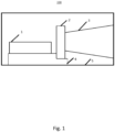
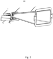
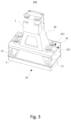
- Fig. 1 - Fig. 6 schematically show structural diagrams of a semiconductor laser module from different view angles, according to embodiments of the present disclosure.
- main element symbols 100 - semiconductor laser module; 1 - direct-output type semiconductor laser light source; 2 - lens; 3 - light reflection component; 4 - cooling device; 5 - sealing device; 6 - fixing screw; 30 - cooling structure; 31 - cooling frame; 311 - opening hole; 32 - thermoelectric cooler; 33 - heat dissipation block; 331 - inlet hole; 332 - outlet hole; 34 - contact window; 35 - contact sensor; 41 - accommodating space; 40 - fixing frame; 42 - fixing platform; 421-screw hole; 422 - through hole; 50 - mounting space.
- the medical treatment described in the present disclosure may include but is not limited to dissolving fat, tendering skin, etc. Explanation is given in the embodiment of the present disclosure, taking noninvasive dissolving fat as an example.
- the principle of the present disclosure is: a semiconductor laser with wavelength 700 nm-1550 nm, in particular, with wavelength 1064 nm, is selected (the absorption effect of the laser with the wavelength by adipose tissue is optimal.
- a semiconductor laser is selected which wavelength corresponds to the absorption wavelength of the tissue).
- the adipose tissue of a human body is irradiated intermittently.
- the temperature of the adipose tissue reaches a temperature at which the adipose tissue is emulsified.
- the adipose tissue is decomposed under the emulsifying temperature, and is further absorbed and discharged by the human body. The effect of noninvasive dissolving fat is achieved.
- Fig. 1 is a schematic structural diagram of a semiconductor laser module 100 provided by an embodiment of the present disclosure.
- Fig. 2 is a schematic structural connection diagram of the semiconductor laser module 100 provided by an embodiment of the present disclosure.
- the direct-output type semiconductor laser light source 1 in the embodiment of the present disclosure may be a single-bar or multi-bar semiconductor laser, a single emitter or multi-single emitter semiconductor laser or other types of semiconductor lasers including but not limited to an edge emitting semiconductor laser light source or a surface emitting semiconductor laser light source, etc.
- the number of the lasers can be set as one or more according to actual needs.
- the semiconductor laser module 100 mainly comprises: a direct-output type semiconductor laser light source 1 configured to perform noninvasive treatment through emitting a laser beam which fast axis divergence angle is 0 -80 degrees and which slow axis divergence angle is 0 -15 degrees (the range of the fast axis divergence angle and the range of the slow axis divergence angle described here are only used for illustration).
- the noninvasive treatment is carried out in a way of extracorporeal irradiation.
- the semiconductor laser module 100 further comprises a beam shaping device.
- the light beam shaping device may comprise a lens 2 and a light reflection component 3.
- the lens 2 and the light reflection component 3 are sequentially disposed in the light-exit direction of the direct-output type semiconductor laser light source 1.
- the beam shaping device is configured to homogenize and expand the laser emitted by the direct-output type semiconductor laser light source 1.
- the light reflection component 3 is mainly used to homogenize the laser beam outputted by the direct-output type semiconductor laser light source 1.
- the homogenization may concretely be: shape a laser beam outputted by the direct-output type semiconductor laser light source which is in gaussian distribution into a laser beam which is in flat top distribution.
- the lens 2 is disposed between the direct-output type semiconductor laser light source 1 and the light reflection component 3, and is used to perform fast-axis and/or slow-axis beam expansion for the laser beam outputted by the direct-output type semiconductor laser light source 1.
- the arrangement of the lens 2 is not necessary.
- the direct-output semiconductor laser light source 1 is a surface emitting semiconductor laser light source
- the fast axis divergence angle of the surface emitting semiconductor laser light source is in agreement with the slow axis divergence angle, so that the process of the fast axis and/or the slow axis expansion for the laser beam can be omitted.
- the arrangement of the lens 2 can be omitted.
- the lens 2 can be arranged.
- the main usage is to perform slow-axis beam expansion for the laser beam outputted by the edge emitting semiconductor laser light source to obtain a homogenized light spot with the specific size. If there is no specific size requirement for the outputted homogenized light spot, the arrangement of the lens 2 can be omitted.
- the light reflection component 3 and the lens 2 are fixed together through a fixing screw 6.
- the number of the lenses 2 may be one or more. The specific number can be determined according to actual requirements.
- the lens 2 may be a general lens such as a cylindrical mirror, and may also be a diffraction device etc. A device, as long as the device can realize beam expansion effect for a laser beam, should be comprised in the scope of the present disclosure.
- the light reflection component 3 may include but not limited to any optical device such as a reflecting cover, a reflection bowl, etc., which can homogenize a laser beam.
- the light reflection component 3 may be a hollow component.
- the matrix material for the light reflection component 3 may include but not limited to: metal (such as stainless steel and nickel), or plastic etc.
- the inner wall of the light reflection component 3 may be configured to realize that the laser beam is reflected on the inner wall of the light reflection component, to form a homogenized light path.
- the inner wall of the light reflection component 3 may also be plated with a reflecting medium.
- the reflecting medium may include but not limited to any one or more kinds of medium materials such as metal (for example, gold), etc., which can realize light reflection.
- the inner wall of a light reflection component which is made of some matrix materials (such as metal), has a reflecting characteristic, so that it is not necessary to plate reflecting medium on the inner part of the light reflection component.
- the cross section of the light reflection component 3 can be square, or round, or polygonal, etc.
- the cross-sectional area of the laser beam input end of the light reflection component 3 is smaller than or equal to the cross-sectional area of the laser beam output end.
- the caliber of the light reflection component 3 may gradually increase from the laser beam input end to the laser beam output end, may also be kept unchanged from the laser beam input end to the laser output end.
- the module may also comprise a cooling device 4.
- the cooling device 4 may be a liquid cooling type cooling device configured to dissipate heat for the direct-output type semiconductor laser light source 1 to guarantee that the direct-output type semiconductor laser light source 1 can normally continuously work.
- the module may also comprise a sealing device 5.
- the sealing device 5 is mainly used for sealing and supporting the semiconductor laser module.
- a screw hole is disposed at the light reflection component 3, and is configured to connect and fix the light reflection component 3 with the sealing device 5 together.
- the sealing device 5 is a hollow shell-shaped component.
- a light outlet is disposed at the sealing device 5.
- the light outlet is configured to apply the homogenized and expanded laser to the to-be-treated region in a way of extracorporeal irradiation.
- the sealing device 5 may be manufactured into various shapes according to requirements. It should be noted that in an example of noninvasive dissolving fat, the wavelength of the light beam emitted by the semiconductor laser module 100 is preferably selected as 1064 nm.
- the semiconductor laser module 100 provided by the embodiment of the present disclosure further comprises a cooling structure 30.
- the cooling structure 30 is disposed on the periphery of the light beam shaping device, and is configured to cool the light beam shaping device and cool local skin heated.
- Fig. 3 - Fig. 6 are schematic structural diagrams of the semiconductor laser module 100 provided by the embodiment of the prevent disclosure, from four view angles.
- the cooling structure 30 comprises a cooling frame 31, a thermoelectric cooler 32 and a heat dissipation block 33.
- the heat dissipation block 33 is disposed on the periphery of the light beam shaping device. Concretely, the heat dissipation block 33 is disposed on the periphery of the light reflection component 3.
- the cooling frame 31 is disposed on the periphery of the heat dissipation block 33.
- the thermoelectric cooler 32 is disposed between the heat dissipation block 33 and the cooling frame 31, and is in contact with the heat dissipation block 33 and the cooling frame 31.
- the heat dissipating block 33 is configured to cool the light reflection component 3 and the thermoelectric cooler 32.
- the thermoelectric cooler 32 is configured to cool the cooling frame 31.
- a concrete contact or connection way among the cooling frame 31, the thermoelectric cooler 32 and the heat dissipation block 33 may be: a through hole structure may be disposed at the cooling frame 31; a structure having a threaded hole may be disposed at the heat dissipation block 33; the thermoelectric cooler 32 is clamped between the cooling frame 31 and the heat dissipation block 33; the cold surface of the thermoelectric cooler 32 is in contact with the cooling frame 31; the hot surface of the thermoelectric cooler 32 is in contact with the heat dissipation block 33; and finally a screw can be used to penetrate through the through hole in the cooling frame 31 and the threaded hole in the heat dissipation block 33.
- a screw can be used to penetrate through the through hole in the cooling frame 31 and the threaded hole in the heat dissipation block 33.
- the cooling frame 31 is connected with the contact window 34.
- the contact window 34 is configured to be in contact with skin of a human body.
- the contact window 34 on the one hand, can flatten the skin to guarantee full contact and uniform irradiation; on the other hand, can cool the skin based on the cooling frame 31.
- the material for the contact window 34 needs to have high thermal conductivity.
- the contact window 34 may be made of sapphire.
- the semiconductor laser module 100 may further comprise a fixing frame 40 to fix the light beam shaping device and the cooling structure 30.
- a fixing frame 40 to fix the light beam shaping device and the cooling structure 30.
- one end of the fixing frame 40 is connected with the direct-output type semiconductor laser light source 1.
- the fixing frame 40 forms an accommodating space 41.
- the accommodating space 41 may be surrounded by the frame of the fixing frame 40.
- the accommodating space 41 is configured to accommodate the beam shaping device.
- a reflecting cover or a reflecting bowl of the light beam shaping device can be contained in the accommodating space 41.
- the working principle of the cooling structure 30 provided by the embodiment is:
- the heat dissipation block 33 is in contact with the beam shaping device and the thermoelectric cooler 32, to cool the light beam shaping device and the thermoelectric cooler 32.
- the thermoelectric cooler 32 is configured to cool the cooling frame 31. Because the cooling frame 31 is directly connected with the contact window 34, the contact window 34 is rapidly cooled. The contact window 34 is in contact with the skin. Therefore, rapid cooling for the skin of the to-be-treated region is achieved.
- the embodiment has no limit for cooling way of the heat dissipation block 33.
- a cooling loop is disposed in the heat dissipation block 33.
- the cooling loop comprises an inlet hole 331 and an outlet hole 332.
- the inlet hole 331 is connected with the outlet hole 332.
- the cooling loop may achieve cooling effect through cooling gas or liquid.
- the cooling loop performs cooling by introducing cooling liquid.
- the inlet hole 331 is configured to input a cooling liquid.
- the outlet hole 332 is configured to output the cooling liquid.
- the cooling liquid entering the cooling loop through the inlet hole 331 takes away the heat of the heat dissipation block 33 and then flows out of the cooling loop through the outlet hole 332. Thus, cooling effect is achieved.
- the embodiment has no limit that the position and the number of the inlet holes 331 and the outlet holes 332 of the heat dissipation block 33 are uniquely defined. Above is only used for illustration and explanation.
- the cooling frame 31 is mounted on the fixing frame 40. Concretely, the other end of the fixing frame 40 extends outwards to form a fixing platform 42.
- the cooling frame 31 is mounted on the fixing platform 42.
- a screw hole 421 may be formed at the fixing platform 42.
- the cooling frame 31 is fixed on the fixing platform 42 through the cooperation between the bolt and the screw hole 421.
- a mounting space 50 is surrounded by the fixing platform 42, the cooling frame 31 and the beam shaping device.
- the mounting space 50 is configured to mount the heat dissipation block 33.
- the number of the mounting spaces 50 can be more than one.
- the number of the heat dissipation blocks 33 is two; the number of the mounting spaces 50 is two; each mounting space 50 contains a heat dissipation block 33.
- the heat dissipation block 33 is mounted in the mounting space 50, so that the space is maximumly utilized.
- the layout is reasonable, so that the volume of the laser treatment head is small. It is convenient for operation.
- a through hole 422 may also be disposed at the fixing platform 42, and be disposed relatively to the inlet hole 331 and the outlet hole 332 of the heat dissipation block 33, so that it is convenient for the inlet hole 331 and the outlet hole 332 pass through the through hole 422, and it is convenient to connect pipes to transport cooling liquid. It is easily understood that, the embodiment has no limit on the number of the through holes 422, which is in agreement with the number of the inlet holes 331 and the outlet holes 332.
- a temperature sensor is disposed on the cooling frame 31 (not shown in the figure).
- the temperature sensor is configured to sense the temperature information of the cooling frame 31.
- the sensed temperature information is sent to a control system.
- the control system may be a control system of the semiconductor laser module 100, so that the control system can adjust the cooling amount of the thermoelectric cooler 32 according to the temperature information. For example, when the temperature of the thermoelectric cooler 32 is too low, the cooling amount of the heat dissipation block 33 is reduced; so that the temperature of the thermoelectric cooler 32 is controlled to rise.
- the temperature sensor may be disposed inside the part of the cooling frame 31 which contacts skin.
- a contact sensor 35 is disposed at the contact window 34, and is configured to sense the fit degree between the contact window 34 and skin of a human body, so as to detect whether the treatment head is in tight contact with the skin of the human body.
- an opening hole 311 is disposed at the cooling frame 31.
- the contact sensor 35 is disposed inside the opening hole 311. The embodiment has no limit on the position and the number of the opening holes 311.
- the semiconductor laser module mainly comprises a direct-output type semiconductor laser light source, a light beam shaping device, and a cooling structure etc.
- the light beam shaping device is disposed in the light-exit direction of the direct-output type semiconductor laser light source.
- the cooling structure comprises a cooling frame, a thermoelectric cooler and a heat dissipation block.
- the heat dissipation block is disposed on the periphery of the light beam shaping device. The heat dissipation block cools the cooling frame through the thermoelectric cooler, to cool the contact window which is in contact with skin.
- the semiconductor laser module provided by the embodiment of the present disclosure fully takes efficient utilization of space into account and reduces the volume of the laser treatment head, through the design of the structure and the position for the heat dissipation block, the thermoelectric cooler, and the cooling frame.
- the problem that local skin temperature rises when laser therapy is performed, is solved. User experience is improved.
- a temperature sensor is disposed at the cooling frame, and can monitor the temperature of the cooling frame in real time. The temperature monitored is fed back to the control system. The control system adjusts the cooling amount of the thermoelectric cooler according to the feedback result. Real-time temperature control and accurate temperature control are achieved.
- the embodiment of the present disclosure further provides a method for noninvasive medical treatment.
- the method utilizes a direct-output type semiconductor laser.
- the direct-output type semiconductor laser comprises the semiconductor laser module described in the above embodiment.
- the method comprises:
- Step S1 a direct-output type semiconductor laser serves as a light source.
- the wavelength of the laser corresponds to the absorption wavelength of tissues of to-be-treated region;
- the direct-output type semiconductor laser light source may emit a laser beam with a certain divergence angle.
- the fast axis divergence angle of the laser beam is 0 - 80 degrees
- the slow axis divergence angle of the laser beam is 0 - 15 degrees (the range of the fast axis divergence angle and the range of the slow axis divergence angle are only used for illustration, without limiting the scheme).
- the "direct-output type semiconductor laser" described in the embodiments of the present disclosure may include but not limited to an edge emitting semiconductor laser light source, or a surface emitting semiconductor laser light source, etc.
- Step S2 the laser is applied to a to-be-treated region in a way of extracorporeal irradiation, to perform noninvasive treatment.
- the industrial practicability of the present invention can achieve good laser treatment effect without causing any trauma on a human body. Noninvasive medical treatment is achieved. Meanwhile, the manufacturing cost is low.
Landscapes
- Health & Medical Sciences (AREA)
- Life Sciences & Earth Sciences (AREA)
- Biomedical Technology (AREA)
- Engineering & Computer Science (AREA)
- Physics & Mathematics (AREA)
- Nuclear Medicine, Radiotherapy & Molecular Imaging (AREA)
- Optics & Photonics (AREA)
- General Health & Medical Sciences (AREA)
- Veterinary Medicine (AREA)
- Public Health (AREA)
- Animal Behavior & Ethology (AREA)
- Surgery (AREA)
- Radiology & Medical Imaging (AREA)
- Pathology (AREA)
- Otolaryngology (AREA)
- Molecular Biology (AREA)
- Medical Informatics (AREA)
- Heart & Thoracic Surgery (AREA)
- Electromagnetism (AREA)
- Biophysics (AREA)
- Radiation-Therapy Devices (AREA)
- Laser Surgery Devices (AREA)
- Semiconductor Lasers (AREA)
Description
- The priority to a China patent application submitted to
China Patent Office on Oct. 17, 2016, which application number is 201610901567.5 China patent office on Oct. 17, 2016, which application number is 201621127578.4 - The disclosure herein relates to the field of semiconductor lasers, particularly relates to a semiconductor laser module and a method for application in noninvasive medical treatment. Documents
WO 2016/074300 A1 ,US 2015/289934 A1 andCN 203 423 371 U disclose different types of laser modules for medical treatment. - As important field of laser application, laser medical treatment and laser beauty have a very rapid development at present. A semiconductor laser has the characteristics: small size, light weight, long service life, and wide wavelength coverage. It is particularly suitable for medical beauty equipment. The application of the semiconductor laser in the area of medical beauty treatment mainly comprises removing hair, tendering skin, dissolving fat, etc.
- Taking dissolving fat as an example, the dissolving fat scheme in the prior art mainly comprises the following three schemes:
- Scheme 1: directly irradiate a fat part by an optical fiber coupling type laser. The disadvantage of the scheme is that the cost is high and the structure is complex.
- Scheme 2: suck fat through an operation in a body. The purpose of reducing fat is achieved through directly stripping the fat in a body by a surgical operation. The disadvantage of the scheme is that there is trauma, the recovery is slow, and the risk is high.
- Scheme 3: dissolve fat with ultrasonic wave. The purpose of reducing fat is achieved through focusing an ultrasonic wave in a fat layer inside a body, heating the fat, and causing the internal metabolism of the adipose tissues. The disadvantage of the scheme is that: the realization needs enough thickness of the fat layer, meanwhile, the focusing depth is not easy to control, and heating adipose tissues without distinction can cause risk of damaging nerve.
- In consideration of the disadvantages of the above schemes, a laser medical method which does not cause trauma and which has remarkable effect is urgently needed.
- The invention is as defined in the appended claims. In view of the above, the main purpose of the present discloure is to provide a semiconductor laser module and a method. The characteristics of the scheme is: based on a direct-output type semiconductor laser, using the technical scheme provided by the present disclosure, the purpose of treatment can be achieved by extracorporeal irradiation without causing any trauma on the human body; also, the cost is low and the treatment effect is good.
- The technical scheme of the disclosure is as follows:
- In the first aspect, an embodiment of the present disclosure provides a semiconductor laser module. The semiconductor laser module comprises: a direct-output type semiconductor laser light source, and a light beam shaping device disposed in the light-exit direction of the direct-output type semiconductor laser light source. The light beam shaping device comprises a light reflection component configured to homogenize the laser beam outputted by the direct-output type semiconductor laser light source.
- Further, the light beam shaping device also comprises a lens. The lens is disposed between the direct-output type semiconductor laser light source and the light reflection component, and is used to carry out fast-axis and/or slow-axis beam expansion for the laser beam outputted by the direct-output type semiconductor laser light source.
- Further, the light reflection component is a hollow component. The matrix material for the light reflection component comprises metal or plastic. The inner wall of the light reflection component is configured to achieve that the laser beam is reflected on the inner wall of the light reflection component, to form a uniform light path.
- Further, a reflecting medium is plated on the inner wall of the light reflection component. The reflecting medium comprises metal.
- Further, the cross section of the light reflection component is square, or circular, or polygonal. The cross-sectional area of the laser beam input end of the light reflection component is smaller than or equal to the cross-sectional area of the laser beam output end.
- Further, the number of the lenses is one or more. The light reflection component is a reflecting bowl or a reflecting cover.
- Further, the module also comprises a cooling structure. The cooling structure is disposed on the periphery of the light reflection component. The cooling structure comprises a cooling frame, a thermoelectric cooler and a heat dissipation block.
- Here, the heat dissipation block is disposed on the periphery of the light reflection component. The heat dissipation block is configured to cool the light reflection component and the thermoelectric cooler. The thermoelectric cooler is configured to cool the cooling frame. The cooling frame is disposed on the periphery of the heat dissipation block. The thermoelectric cooler is disposed between the heat dissipation block and the cooling frame, and is in contact with the heat dissipation block and the cooling frame.
- Further, a temperature sensor is disposed inside the cooling frame and is configured to sense the temperature information of the cooling frame. The sensed temperature information is sent to a control system, so that the control system adjusts the cooling amount of the thermoelectric cooler according to the temperature information.
- Further, a contact window used for contacting skin and cooling the skin is disposed at the cooling frame. The cooling frame is used for cooling the contact window. A contact sensor is disposed at the contact window. The contact sensor is configured to sense the fit degree between the contact window and the skin.
- Further, the module also comprises a fixing frame. One end of the fixing frame is connected with the direct-output type semiconductor laser light source. The fixing frame forms an accommodating space configured to accommodate the light beam shaping device.
- Further, the other end of the fixing frame extends outwards to form a fixing platform. The cooling frame is disposed on the fixing platform. A mounting space is surrounded by the fixing platform, the cooling frame, and the light reflection component. The mounting space is configured to mount the heat dissipation block.
- Further, the heat dissipation block comprises a cooling loop. The cooling loop comprises an inlet hole and an outlet hole. A through hole is disposed at the fixing platform. The inlet hole and the outlet hole penetrate through the through hole. The cooling loop is a liquid cooling loop. The inlet hole is configured to input a cooling liquid. The outlet hole is configured to output the cooling liquid.
- Further, the module also comprise a sealing device configured to seal and support the semiconductor laser module.
- Further, the sealing device is a hollow shell-shaped component. A light outlet is disposed at the sealing device. The light outlet is configured to apply the homogenized laser beam to a to-be-treated region in a way of extracorporeal irradiation.
- In the second aspect, the embodiment of the disclosure provides a noninvasive medical treatment method. The method utilizes a direct-output type semiconductor laser. The direct-output type semiconductor laser comprises a semiconductor laser module described in the first aspect of the embodiment of the present disclosure. The method comprises:
- The direct-output type semiconductor laser serves as a light source. The wavelength of the laser emitted by the light source corresponds to the absorption wavelength of tissues of the to-be-treated region. The laser acts on the to-be-treated region in a way of extracorporeal irradiation, to carry out a noninvasive treatment.
- The technical scheme disclosed in the present disclosure uses the direct-output type semiconductor laser as a light source. The characteristic that a semiconductor laser has large divergence angle, is fully utilized. Noninvasive treatment is realized through large-area light spot irradiation outside a body. Through the technical scheme provided by the present invention, a very good treatment effect is achieved without causing any trauma on a human body. Noninvasive medical treatment is successfully realized. In view of cost, the high cost problem of a traditional optical fiber coupling type scheme is solved, by the scheme of the present disclosure which is based on the direct-output type semiconductor laser.
- In addition, the effectiveness of space utilization is fully considered by the design of the structure and the position of the cooling structure of the semiconductor laser module. The volume of the laser treatment head is reduced. The problem that local skin temperature rises when laser therapy is carried out, is solved. User experience is improved.
- In addition, the temperature sensor disposed on the cooling frame can monitor the temperature of the cooling frame in real time. The temperature is fed back to the control system. The control system adjusts the cooling amount of the thermoelectric cooler according to the feedback result, to achieve real-time temperature control and accurate temperature control.
- In order to clearly explain the technical schemes of the embodiments of the present disclosure, the figures which usage is needed in the embodiments are introduced briefly as follows. It should be understood that the following figures only show some embodiments of the present disclosure, thus, should not be regarded as limitation on the range. For a technical person with ordinary skills in the art, according to these figures, other related figures can be obtained without creative effort.
-
Fig. 1 - Fig. 6 schematically show structural diagrams of a semiconductor laser module from different view angles, according to embodiments of the present disclosure. - The explanation for main element symbols:
100 - semiconductor laser module; 1 - direct-output type semiconductor laser light source; 2 - lens; 3 - light reflection component; 4 - cooling device; 5 - sealing device; 6 - fixing screw; 30 - cooling structure; 31 - cooling frame; 311 - opening hole; 32 - thermoelectric cooler; 33 - heat dissipation block; 331 - inlet hole; 332 - outlet hole; 34 - contact window; 35 - contact sensor; 41 - accommodating space; 40 - fixing frame; 42 - fixing platform; 421-screw hole; 422 - through hole; 50 - mounting space. - Through a semiconductor laser module provided by an embodiment of the present disclosure, a remarkable medical effect can be achieved without causing any trauma on a human body. The medical treatment described in the present disclosure may include but is not limited to dissolving fat, tendering skin, etc. Explanation is given in the embodiment of the present disclosure, taking noninvasive dissolving fat as an example.
- The principle of the present disclosure is: a semiconductor laser with wavelength 700 nm-1550 nm, in particular, with wavelength 1064 nm, is selected (the absorption effect of the laser with the wavelength by adipose tissue is optimal. For another tissue, a semiconductor laser is selected which wavelength corresponds to the absorption wavelength of the tissue). Using characteristics of the semiconductor laser that the divergence angle is large, through a way of large-area light spot irradiation, the adipose tissue of a human body is irradiated intermittently. Thus, the temperature of the adipose tissue reaches a temperature at which the adipose tissue is emulsified. The adipose tissue is decomposed under the emulsifying temperature, and is further absorbed and discharged by the human body. The effect of noninvasive dissolving fat is achieved.
-
Fig. 1 is a schematic structural diagram of asemiconductor laser module 100 provided by an embodiment of the present disclosure.Fig. 2 is a schematic structural connection diagram of thesemiconductor laser module 100 provided by an embodiment of the present disclosure. The direct-output type semiconductorlaser light source 1 in the embodiment of the present disclosure may be a single-bar or multi-bar semiconductor laser, a single emitter or multi-single emitter semiconductor laser or other types of semiconductor lasers including but not limited to an edge emitting semiconductor laser light source or a surface emitting semiconductor laser light source, etc. The number of the lasers can be set as one or more according to actual needs. Thesemiconductor laser module 100 mainly comprises: a direct-output type semiconductorlaser light source 1 configured to perform noninvasive treatment through emitting a laser beam which fast axis divergence angle is 0 -80 degrees and which slow axis divergence angle is 0 -15 degrees (the range of the fast axis divergence angle and the range of the slow axis divergence angle described here are only used for illustration). The noninvasive treatment is carried out in a way of extracorporeal irradiation. - The
semiconductor laser module 100 further comprises a beam shaping device. Concretely, the light beam shaping device may comprise alens 2 and alight reflection component 3. Thelens 2 and thelight reflection component 3 are sequentially disposed in the light-exit direction of the direct-output type semiconductorlaser light source 1. The beam shaping device is configured to homogenize and expand the laser emitted by the direct-output type semiconductorlaser light source 1. - Here, the
light reflection component 3 is mainly used to homogenize the laser beam outputted by the direct-output type semiconductorlaser light source 1. The homogenization may concretely be: shape a laser beam outputted by the direct-output type semiconductor laser light source which is in gaussian distribution into a laser beam which is in flat top distribution. - The
lens 2 is disposed between the direct-output type semiconductorlaser light source 1 and thelight reflection component 3, and is used to perform fast-axis and/or slow-axis beam expansion for the laser beam outputted by the direct-output type semiconductorlaser light source 1. - It should be noted that the arrangement of the
lens 2 is not necessary. In other words: when the direct-output semiconductorlaser light source 1 is a surface emitting semiconductor laser light source, because the fast axis divergence angle of the surface emitting semiconductor laser light source is in agreement with the slow axis divergence angle, so that the process of the fast axis and/or the slow axis expansion for the laser beam can be omitted. In other words, under such situation, the arrangement of thelens 2 can be omitted. - Further, when the direct-output type semiconductor
laser light source 1 is an edge emitting semiconductor laser light source, in order to achieve a homogenized light spot with certain specific size requirement, thelens 2 can be arranged. The main usage is to perform slow-axis beam expansion for the laser beam outputted by the edge emitting semiconductor laser light source to obtain a homogenized light spot with the specific size. If there is no specific size requirement for the outputted homogenized light spot, the arrangement of thelens 2 can be omitted. - In practical application, the
light reflection component 3 and thelens 2 are fixed together through a fixingscrew 6. It should be noted that the number of thelenses 2 may be one or more. The specific number can be determined according to actual requirements. Thelens 2 may be a general lens such as a cylindrical mirror, and may also be a diffraction device etc. A device, as long as the device can realize beam expansion effect for a laser beam, should be comprised in the scope of the present disclosure. Thelight reflection component 3 may include but not limited to any optical device such as a reflecting cover, a reflection bowl, etc., which can homogenize a laser beam. - Concretely, the
light reflection component 3 may be a hollow component. The matrix material for thelight reflection component 3 may include but not limited to: metal (such as stainless steel and nickel), or plastic etc. The inner wall of thelight reflection component 3 may be configured to realize that the laser beam is reflected on the inner wall of the light reflection component, to form a homogenized light path. - Preferably, the inner wall of the
light reflection component 3 may also be plated with a reflecting medium. The reflecting medium may include but not limited to any one or more kinds of medium materials such as metal (for example, gold), etc., which can realize light reflection. - As to the above, it should be noted that: because the inner wall of a light reflection component, which is made of some matrix materials (such as metal), has a reflecting characteristic, so that it is not necessary to plate reflecting medium on the inner part of the light reflection component.
- Further, the cross section of the
light reflection component 3 can be square, or round, or polygonal, etc. The cross-sectional area of the laser beam input end of thelight reflection component 3 is smaller than or equal to the cross-sectional area of the laser beam output end. In other words, the caliber of thelight reflection component 3, may gradually increase from the laser beam input end to the laser beam output end, may also be kept unchanged from the laser beam input end to the laser output end. - Further, the module may also comprise a
cooling device 4. Thecooling device 4 may be a liquid cooling type cooling device configured to dissipate heat for the direct-output type semiconductorlaser light source 1 to guarantee that the direct-output type semiconductorlaser light source 1 can normally continuously work. - Further, the module may also comprise a
sealing device 5. Thesealing device 5 is mainly used for sealing and supporting the semiconductor laser module. A screw hole is disposed at thelight reflection component 3, and is configured to connect and fix thelight reflection component 3 with thesealing device 5 together. - Concretely, the
sealing device 5 is a hollow shell-shaped component. A light outlet is disposed at thesealing device 5. The light outlet is configured to apply the homogenized and expanded laser to the to-be-treated region in a way of extracorporeal irradiation. In practice, thesealing device 5 may be manufactured into various shapes according to requirements. It should be noted that in an example of noninvasive dissolving fat, the wavelength of the light beam emitted by thesemiconductor laser module 100 is preferably selected as 1064 nm. - The
semiconductor laser module 100 provided by the embodiment of the present disclosure further comprises acooling structure 30. The coolingstructure 30 is disposed on the periphery of the light beam shaping device, and is configured to cool the light beam shaping device and cool local skin heated.Fig. 3 - Fig. 6 are schematic structural diagrams of thesemiconductor laser module 100 provided by the embodiment of the prevent disclosure, from four view angles. The coolingstructure 30 comprises acooling frame 31, athermoelectric cooler 32 and aheat dissipation block 33. Here, theheat dissipation block 33 is disposed on the periphery of the light beam shaping device. Concretely, theheat dissipation block 33 is disposed on the periphery of thelight reflection component 3. The coolingframe 31 is disposed on the periphery of theheat dissipation block 33. Thethermoelectric cooler 32 is disposed between theheat dissipation block 33 and thecooling frame 31, and is in contact with theheat dissipation block 33 and thecooling frame 31. Theheat dissipating block 33 is configured to cool thelight reflection component 3 and thethermoelectric cooler 32. Thethermoelectric cooler 32 is configured to cool thecooling frame 31. - Here, a concrete contact or connection way among the cooling
frame 31, thethermoelectric cooler 32 and theheat dissipation block 33 may be: a through hole structure may be disposed at thecooling frame 31; a structure having a threaded hole may be disposed at theheat dissipation block 33; thethermoelectric cooler 32 is clamped between the coolingframe 31 and theheat dissipation block 33; the cold surface of thethermoelectric cooler 32 is in contact with thecooling frame 31; the hot surface of thethermoelectric cooler 32 is in contact with theheat dissipation block 33; and finally a screw can be used to penetrate through the through hole in thecooling frame 31 and the threaded hole in theheat dissipation block 33. Thus, the contact or connection among the three components is realized. - The cooling
frame 31 is connected with thecontact window 34. Thecontact window 34 is configured to be in contact with skin of a human body. Thecontact window 34, on the one hand, can flatten the skin to guarantee full contact and uniform irradiation; on the other hand, can cool the skin based on thecooling frame 31. In order to ensure rapid cooling, the material for thecontact window 34 needs to have high thermal conductivity. In the embodiment, thecontact window 34 may be made of sapphire. - In the embodiment, the
semiconductor laser module 100 may further comprise a fixingframe 40 to fix the light beam shaping device and the coolingstructure 30. Here, one end of the fixingframe 40 is connected with the direct-output type semiconductorlaser light source 1. The fixingframe 40 forms anaccommodating space 41. Theaccommodating space 41 may be surrounded by the frame of the fixingframe 40. Theaccommodating space 41 is configured to accommodate the beam shaping device. For example, a reflecting cover or a reflecting bowl of the light beam shaping device can be contained in theaccommodating space 41. - The working principle of the cooling
structure 30 provided by the embodiment is: - The
heat dissipation block 33 is in contact with the beam shaping device and thethermoelectric cooler 32, to cool the light beam shaping device and thethermoelectric cooler 32. Thethermoelectric cooler 32 is configured to cool thecooling frame 31. Because thecooling frame 31 is directly connected with thecontact window 34, thecontact window 34 is rapidly cooled. Thecontact window 34 is in contact with the skin. Therefore, rapid cooling for the skin of the to-be-treated region is achieved. - The embodiment has no limit for cooling way of the
heat dissipation block 33. In the embodiment, a cooling loop is disposed in theheat dissipation block 33. The cooling loop comprises aninlet hole 331 and anoutlet hole 332. Theinlet hole 331 is connected with theoutlet hole 332. The cooling loop may achieve cooling effect through cooling gas or liquid. In the embodiment, the cooling loop performs cooling by introducing cooling liquid. Concretely, theinlet hole 331 is configured to input a cooling liquid. Theoutlet hole 332 is configured to output the cooling liquid. The cooling liquid entering the cooling loop through theinlet hole 331 takes away the heat of theheat dissipation block 33 and then flows out of the cooling loop through theoutlet hole 332. Thus, cooling effect is achieved. In order to enhance the heat dissipation effect of theheat dissipation block 33, to make theheat dissipation block 33 be more easily cooled, material with high heat conductivity is selected for theheat dissipation block 33. It should be noted that the embodiment has no limit that the position and the number of the inlet holes 331 and the outlet holes 332 of theheat dissipation block 33 are uniquely defined. Above is only used for illustration and explanation. - The cooling
frame 31 is mounted on the fixingframe 40. Concretely, the other end of the fixingframe 40 extends outwards to form a fixingplatform 42. The coolingframe 31 is mounted on the fixingplatform 42. For example, ascrew hole 421 may be formed at the fixingplatform 42. The coolingframe 31 is fixed on the fixingplatform 42 through the cooperation between the bolt and thescrew hole 421. - A mounting
space 50 is surrounded by the fixingplatform 42, the coolingframe 31 and the beam shaping device. The mountingspace 50 is configured to mount theheat dissipation block 33. It is easily understood that the number of the mountingspaces 50 can be more than one. For example, the number of the heat dissipation blocks 33 is two; the number of the mountingspaces 50 is two; each mountingspace 50 contains aheat dissipation block 33. Theheat dissipation block 33 is mounted in the mountingspace 50, so that the space is maximumly utilized. The layout is reasonable, so that the volume of the laser treatment head is small. It is convenient for operation. - A through
hole 422 may also be disposed at the fixingplatform 42, and be disposed relatively to theinlet hole 331 and theoutlet hole 332 of theheat dissipation block 33, so that it is convenient for theinlet hole 331 and theoutlet hole 332 pass through the throughhole 422, and it is convenient to connect pipes to transport cooling liquid. It is easily understood that, the embodiment has no limit on the number of the throughholes 422, which is in agreement with the number of the inlet holes 331 and the outlet holes 332. - In addition, a temperature sensor is disposed on the cooling frame 31 (not shown in the figure). The temperature sensor is configured to sense the temperature information of the
cooling frame 31. The sensed temperature information is sent to a control system. The control system may be a control system of thesemiconductor laser module 100, so that the control system can adjust the cooling amount of thethermoelectric cooler 32 according to the temperature information. For example, when the temperature of thethermoelectric cooler 32 is too low, the cooling amount of theheat dissipation block 33 is reduced; so that the temperature of thethermoelectric cooler 32 is controlled to rise. The temperature sensor may be disposed inside the part of thecooling frame 31 which contacts skin. - In addition, a
contact sensor 35 is disposed at thecontact window 34, and is configured to sense the fit degree between thecontact window 34 and skin of a human body, so as to detect whether the treatment head is in tight contact with the skin of the human body. Concretely, anopening hole 311 is disposed at thecooling frame 31. Thecontact sensor 35 is disposed inside theopening hole 311. The embodiment has no limit on the position and the number of the opening holes 311. - In summary, the semiconductor laser module provided by the embodiment of the present disclosure, mainly comprises a direct-output type semiconductor laser light source, a light beam shaping device, and a cooling structure etc. The light beam shaping device is disposed in the light-exit direction of the direct-output type semiconductor laser light source. The cooling structure comprises a cooling frame, a thermoelectric cooler and a heat dissipation block. The heat dissipation block is disposed on the periphery of the light beam shaping device. The heat dissipation block cools the cooling frame through the thermoelectric cooler, to cool the contact window which is in contact with skin. The semiconductor laser module provided by the embodiment of the present disclosure fully takes efficient utilization of space into account and reduces the volume of the laser treatment head, through the design of the structure and the position for the heat dissipation block, the thermoelectric cooler, and the cooling frame. The problem that local skin temperature rises when laser therapy is performed, is solved. User experience is improved.
- In addition, a temperature sensor is disposed at the cooling frame, and can monitor the temperature of the cooling frame in real time. The temperature monitored is fed back to the control system. The control system adjusts the cooling amount of the thermoelectric cooler according to the feedback result. Real-time temperature control and accurate temperature control are achieved.
- In addition, the embodiment of the present disclosure further provides a method for noninvasive medical treatment. The method utilizes a direct-output type semiconductor laser. The direct-output type semiconductor laser comprises the semiconductor laser module described in the above embodiment. The method comprises:
- Step S1, a direct-output type semiconductor laser serves as a light source. The wavelength of the laser corresponds to the absorption wavelength of tissues of to-be-treated region;
- Here, the direct-output type semiconductor laser light source may emit a laser beam with a certain divergence angle. For example, the fast axis divergence angle of the laser beam is 0 - 80 degrees, the slow axis divergence angle of the laser beam is 0 - 15 degrees (the range of the fast axis divergence angle and the range of the slow axis divergence angle are only used for illustration, without limiting the scheme).
- Moreover, the "direct-output type semiconductor laser" described in the embodiments of the present disclosure, may include but not limited to an edge emitting semiconductor laser light source, or a surface emitting semiconductor laser light source, etc.
- Step S2, the laser is applied to a to-be-treated region in a way of extracorporeal irradiation, to perform noninvasive treatment.
- The present invention is as defined in the appended claims. The embodiments, aspects or examples according to the present description which do not fall within the scope of said claims are provided for illustrative purposes only and do not form part of the present invention.
- The industrial practicability of the present invention: The invention can achieve good laser treatment effect without causing any trauma on a human body. Noninvasive medical treatment is achieved. Meanwhile, the manufacturing cost is low.
Claims (13)
- A semiconductor laser module (100), wherein the module (100) comprises: a direct-output type semiconductor laser light source (1), and a light beam shaping device disposed in the light-exit direction of the direct-output type semiconductor laser light source (1); wherein the light beam shaping device comprises a light reflection component (3) configured to homogenize the laser beam outputted by the direct-output type semiconductor laser light source (1), wherein the light reflection component (3) is a hollow component; wherein the inner wall of the light reflection component (3) is configured to realize that the laser beam is reflected on the inner wall of the light reflection component (3), to form a uniform light path; wherein the module (100) further comprises a cooling structure (30) disposed on the periphery of the light reflection component (3); wherein the cooling structure (30) comprises a cooling frame (31), a thermoelectric cooler (32) and a heat dissipation block (33), wherein a contact window (34) used for contacting skin and cooling the skin is disposed at the cooling frame (31), wherein the cooling frame (31) is used for cooling the contact window (34); wherein a contact sensor (35) is disposed at the contact window (34), wherein the contact sensor (35) is configured to sense the fit degree between the contact window (34) and the skin.
- The semiconductor laser module (100) of claim 1, wherein the light beam shaping device further comprises a lens (2); wherein the lens (2) is disposed between the direct-output type semiconductor laser light source (1) and the light reflection component (3), and is used for performing fast-axis and/or slow-axis beam expansion for the laser beam outputted by the direct-output type semiconductor laser light source (1).
- The semiconductor laser module (100) of claim 1, wherein the matrix material for the light reflection component (3) comprises metal or plastic.
- The semiconductor laser module (100) of claim 1, wherein the inner wall of the light reflection component (3) is plated with reflecting medium; wherein the reflecting medium comprises metal.
- The semiconductor laser module (100) of claim 1, wherein the cross section of the light reflection component (3) is square, or round, or polygonal; wherein the cross-sectional area of the laser beam input end of the light reflection component (3) is smaller than or equal to the cross-sectional area of the laser beam output end of the light reflection component (3).
- The semiconductor laser module (100) of claim 2, wherein the number of the lenses (2) is one or more; wherein the light reflection component (3) is a reflecting bowl or a reflecting cover.
- The semiconductor laser module (100) of claim 1, wherein the heat dissipation block (33) is disposed on the periphery of the light reflection component (3); wherein the heat dissipation block (33) is configured to cool the light reflection component (3) and the thermoelectric cooler (32); wherein the thermoelectric cooler (32) is configured to cool the cooling frame (3)1; wherein the cooling frame (31) is disposed on the periphery of the heat dissipation block (33); wherein the thermoelectric cooler (32) is disposed between the heat dissipation block (33) and the cooling frame (31), and is in contact with the heat dissipation block (33) and the cooling frame (31).
- The semiconductor laser module (100) of claim 1, wherein a temperature sensor is disposed inside the cooling frame (31) and is configured to sense the temperature information of the cooling frame (31); wherein the sensed temperature information is sent to a control system, so that the control system adjusts the cooling amount of the thermoelectric cooler (32) according to the temperature information.
- The semiconductor laser module (100) of claim 1, wherein the module (100) further comprises a fixing frame (40); wherein one end of the fixing frame (40) is connected with the direct-output type semiconductor laser light source (1); wherein the fixing frame (40) forms an accommodating space (41) configured to accommodate the light beam shaping device.
- The semiconductor laser module (100) of claim 9, wherein the other end of the fixing frame (40) extends outwards to form a fixing platform; wherein the cooling frame is disposed on the fixing platform (42); wherein an mounting space (50) is surrounded by the fixing platform (42), the cooling frame (31) and the light reflection component (3); wherein the mounting space (50) is configured for mounting the heat dissipation block (33).
- The semiconductor laser module (100) of claim 10, wherein the heat dissipation block (33) comprises a cooling loop; wherein the cooling loop comprises an inlet hole (331) and an outlet hole (332); wherein the fixing platform (42) comprises a through hole (422); wherein the inlet hole (331) and the outlet hole (332) penetrate through the through hole (422); wherein the cooling loop is a liquid cooling loop; wherein the inlet hole (331) is configured to input a cooling liquid; wherein the outlet hole (332) is configured to output the cooling liquid.
- The semiconductor laser module (100) of any one of claims 1-11, wherein the module (100) further comprises a sealing device (5) configured to seal and support the semiconductor laser module (100).
- The semiconductor laser module (100) of claim 12, wherein the sealing device (5) is a hollow shell-shaped component; wherein a light outlet is disposed; wherein the light outlet is configured to apply a homogenized laser beam to the to-be-treated region in a way of extracorporeal irradiation.
Applications Claiming Priority (3)
| Application Number | Priority Date | Filing Date | Title |
|---|---|---|---|
| CN201610901567.5A CN106621068A (en) | 2016-10-17 | 2016-10-17 | Semiconductor laser module and method for noninvasive medical treatment |
| CN201621127578.4U CN206404189U (en) | 2016-10-17 | 2016-10-17 | A kind of high-power semiconductor laser for non-invasive medical |
| PCT/CN2017/104023 WO2018072610A1 (en) | 2016-10-17 | 2017-09-28 | Semiconductor laser module and method for application in noninvasive medical treatment |
Publications (3)
| Publication Number | Publication Date |
|---|---|
| EP3527260A1 EP3527260A1 (en) | 2019-08-21 |
| EP3527260A4 EP3527260A4 (en) | 2020-05-13 |
| EP3527260B1 true EP3527260B1 (en) | 2024-04-10 |
Family
ID=62018236
Family Applications (1)
| Application Number | Title | Priority Date | Filing Date |
|---|---|---|---|
| EP17863036.4A Active EP3527260B1 (en) | 2016-10-17 | 2017-09-28 | Semiconductor laser module for application in noninvasive medical treatment |
Country Status (7)
| Country | Link |
|---|---|
| US (1) | US12256988B2 (en) |
| EP (1) | EP3527260B1 (en) |
| KR (1) | KR102293502B1 (en) |
| CN (1) | CN108348766B (en) |
| ES (1) | ES2981270T3 (en) |
| RU (1) | RU2723337C1 (en) |
| WO (1) | WO2018072610A1 (en) |
Families Citing this family (6)
| Publication number | Priority date | Publication date | Assignee | Title |
|---|---|---|---|---|
| KR102168060B1 (en) * | 2019-01-02 | 2020-10-21 | 주식회사 은성글로벌 | Handpiece for skin treatment |
| US20200402692A1 (en) * | 2019-06-18 | 2020-12-24 | Massachusetts Institute Of Technology | Control system for charging of non/partially insulated superconducting magnets and related techniques |
| CN112212227B (en) * | 2020-10-14 | 2021-04-02 | 爱眼(广州)医疗科技有限公司 | Light emitting module applied to treatment of amblyopia and myopia |
| CN112618012B (en) * | 2020-12-17 | 2023-04-07 | 武汉奇致激光技术股份有限公司 | Safety protection device for semiconductor laser depilator and control method |
| CN115957001A (en) * | 2023-01-04 | 2023-04-14 | 武汉长江激光科技有限公司 | Laser beauty equipment and laser scanning control method |
| CN220122327U (en) * | 2023-06-25 | 2023-12-01 | 西安炬光科技股份有限公司 | Laser module and medical device |
Citations (7)
| Publication number | Priority date | Publication date | Assignee | Title |
|---|---|---|---|---|
| US5870133A (en) * | 1995-04-28 | 1999-02-09 | Minolta Co., Ltd. | Laser scanning device and light source thereof having temperature correction capability |
| US20020128696A1 (en) * | 2001-03-06 | 2002-09-12 | Henry Pearl | Apparatus and method for stimulating hair growth |
| US20040201898A1 (en) * | 2003-04-11 | 2004-10-14 | Delta Electronics, Inc. | Light-homogenizing device and optical apparatus with light-homogenizing device |
| EP2202569A1 (en) * | 2007-10-01 | 2010-06-30 | Panasonic Corporation | Wavelength conversion laser device and image display device using the same |
| WO2011161126A1 (en) * | 2010-06-21 | 2011-12-29 | Clinical Laserthermia Systems Ab | A system for providing insertable probes |
| EP2749943A1 (en) * | 2011-08-27 | 2014-07-02 | Appotronics Corporation Limited | Projection system and light emitting device thereof |
| US20150289934A1 (en) * | 2012-11-22 | 2015-10-15 | Xi'an Focuslight Technologies Co., Ltd. | Semiconductor laser system for laser medical cosmetology |
Family Cites Families (30)
| Publication number | Priority date | Publication date | Assignee | Title |
|---|---|---|---|---|
| US5625738A (en) * | 1994-06-28 | 1997-04-29 | Corning Incorporated | Apparatus for uniformly illuminating a light valve |
| RU12887U1 (en) | 1998-04-15 | 2000-02-20 | Экспериментальное научно-производственное объединение "Специализированные электронные системы" | LASER MACHINE |
| DE10002329A1 (en) * | 2000-01-20 | 2001-08-02 | Infineon Technologies Ag | Manufacturing process for an optical transmitter assembly |
| ATE326182T1 (en) * | 2000-02-23 | 2006-06-15 | Zeiss Carl Meditec Ag | HANDPIECE FOR RADIATION OF LIGHT ON A SURFACE OF SKIN |
| EP1400832B1 (en) * | 2002-09-19 | 2014-10-22 | Semiconductor Energy Laboratory Co., Ltd. | Beam homogenizer and laser irradiation apparatus and method of manufacturing semiconductor device |
| US7327916B2 (en) * | 2003-03-11 | 2008-02-05 | Semiconductor Energy Laboratory Co., Ltd. | Beam Homogenizer, laser irradiation apparatus, and method of manufacturing a semiconductor device |
| TWI235875B (en) * | 2004-06-08 | 2005-07-11 | Delta Electronics Inc | Projection system and its light tunnel |
| TWI270710B (en) * | 2004-11-24 | 2007-01-11 | Prodisc Technology Inc | Light tunnel with gradient filter device |
| US7889430B2 (en) * | 2006-05-09 | 2011-02-15 | Ostendo Technologies, Inc. | LED-based high efficiency illumination systems for use in projection systems |
| CN200941530Y (en) | 2006-08-08 | 2007-08-29 | 牛建民 | Semiconductor laser speckle generator |
| JP4200333B2 (en) | 2006-11-16 | 2008-12-24 | パナソニック電工株式会社 | Optical hair removal device |
| WO2011143663A2 (en) * | 2010-05-14 | 2011-11-17 | Xintec Corporation | Laser beam control and delivery system |
| US8403527B2 (en) * | 2010-10-26 | 2013-03-26 | Thomas J. Brukilacchio | Light emitting diode projector |
| WO2012106689A1 (en) * | 2011-02-03 | 2012-08-09 | Tria Beauty, Inc. | Radiation-based dermatological devices and methods |
| JP2015028501A (en) * | 2011-11-24 | 2015-02-12 | 住友電気工業株式会社 | Wavelength converter and laser device |
| CN103178432A (en) | 2011-12-20 | 2013-06-26 | 常州第二电子仪器有限公司 | Temperature control device of semiconductor pump laser |
| CN102935012B (en) | 2012-11-22 | 2015-06-17 | 西安炬光科技有限公司 | Two-side refrigerating type semiconductor laser system for medical cosmetology |
| WO2014079374A1 (en) * | 2012-11-22 | 2014-05-30 | 西安炬光科技有限公司 | Bilateral cooling type semiconductor laser system for medical beauty use |
| CN102940529B (en) | 2012-11-22 | 2015-04-01 | 西安炬光科技有限公司 | Semiconductor laser device system used for laser medical cosmetology |
| RU133723U1 (en) | 2013-06-04 | 2013-10-27 | Общество с ограниченной ответственностью "ЭЙРА" | DEVICE FOR LASER VISION STIMULATION |
| CN203423371U (en) | 2013-08-28 | 2014-02-05 | 武汉洛芙科技有限公司 | Semiconductor laser for medical use |
| CN103941406B (en) * | 2014-05-09 | 2017-01-25 | 西安炬光科技有限公司 | High-power semiconductor laser optical shaping method and device based on beam expanding |
| CN203988360U (en) | 2014-07-10 | 2014-12-10 | 山东神思医疗设备有限公司 | The laser therapeutic head of output square focus spot |
| PL3219360T3 (en) | 2014-11-10 | 2020-10-19 | Sanhe Laserconn Tech Co., Ltd. | High power vcsel laser treatment device with skin cooling function and packaging structure thereof |
| EP3234455B1 (en) * | 2014-12-16 | 2023-08-23 | Cellomics, Inc | Optic homogenizer |
| CN104688337B (en) | 2015-02-03 | 2018-01-09 | 中国科学院苏州生物医学工程技术研究所 | A kind of laser therapeutic system of ablation of tissue |
| US10518104B2 (en) | 2015-04-23 | 2019-12-31 | Cynosure, Llc | Systems and methods of unattended treatment |
| CN106621068A (en) | 2016-10-17 | 2017-05-10 | 镭蒙(苏州)微光学科技有限公司 | Semiconductor laser module and method for noninvasive medical treatment |
| CN206404189U (en) | 2016-10-17 | 2017-08-15 | 镭蒙(苏州)微光学科技有限公司 | A kind of high-power semiconductor laser for non-invasive medical |
| KR102038941B1 (en) * | 2017-12-19 | 2019-10-31 | 주식회사 하이로닉 | Handpiece for laser operation and fat reduction apparatus with the same |
-
2017
- 2017-09-28 RU RU2019113825A patent/RU2723337C1/en active
- 2017-09-28 KR KR1020197014164A patent/KR102293502B1/en active Active
- 2017-09-28 WO PCT/CN2017/104023 patent/WO2018072610A1/en not_active Ceased
- 2017-09-28 ES ES17863036T patent/ES2981270T3/en active Active
- 2017-09-28 EP EP17863036.4A patent/EP3527260B1/en active Active
- 2017-09-28 CN CN201780002184.7A patent/CN108348766B/en active Active
- 2017-09-28 US US16/341,937 patent/US12256988B2/en active Active
Patent Citations (7)
| Publication number | Priority date | Publication date | Assignee | Title |
|---|---|---|---|---|
| US5870133A (en) * | 1995-04-28 | 1999-02-09 | Minolta Co., Ltd. | Laser scanning device and light source thereof having temperature correction capability |
| US20020128696A1 (en) * | 2001-03-06 | 2002-09-12 | Henry Pearl | Apparatus and method for stimulating hair growth |
| US20040201898A1 (en) * | 2003-04-11 | 2004-10-14 | Delta Electronics, Inc. | Light-homogenizing device and optical apparatus with light-homogenizing device |
| EP2202569A1 (en) * | 2007-10-01 | 2010-06-30 | Panasonic Corporation | Wavelength conversion laser device and image display device using the same |
| WO2011161126A1 (en) * | 2010-06-21 | 2011-12-29 | Clinical Laserthermia Systems Ab | A system for providing insertable probes |
| EP2749943A1 (en) * | 2011-08-27 | 2014-07-02 | Appotronics Corporation Limited | Projection system and light emitting device thereof |
| US20150289934A1 (en) * | 2012-11-22 | 2015-10-15 | Xi'an Focuslight Technologies Co., Ltd. | Semiconductor laser system for laser medical cosmetology |
Also Published As
| Publication number | Publication date |
|---|---|
| KR102293502B1 (en) | 2021-08-26 |
| EP3527260A1 (en) | 2019-08-21 |
| CN108348766A (en) | 2018-07-31 |
| KR20190071761A (en) | 2019-06-24 |
| EP3527260A4 (en) | 2020-05-13 |
| WO2018072610A1 (en) | 2018-04-26 |
| CN108348766B (en) | 2019-10-18 |
| US12256988B2 (en) | 2025-03-25 |
| ES2981270T3 (en) | 2024-10-08 |
| RU2723337C1 (en) | 2020-06-09 |
| US20190239951A1 (en) | 2019-08-08 |
Similar Documents
| Publication | Publication Date | Title |
|---|---|---|
| US12256988B2 (en) | Semiconductor laser module and method for application in noninvasive medical treatment | |
| CN102742098B (en) | Semiconductor laser assembling and packaging system | |
| US20220273964A1 (en) | Systems and Methods for Aesthetic Treatment | |
| JP2022542908A5 (en) | ||
| JP2015513947A5 (en) | ||
| KR20180041465A (en) | Laser handpiece for skin treatment | |
| CN118920261A (en) | Multi-power head-replaceable semiconductor laser convenient for light spot conversion | |
| AU2020345914B2 (en) | Cooling system for tissue treatment system with both tissue and light source cooling | |
| CN206404189U (en) | A kind of high-power semiconductor laser for non-invasive medical | |
| CN106621068A (en) | Semiconductor laser module and method for noninvasive medical treatment | |
| JP2005152972A (en) | Laser processing equipment | |
| CN115957001A (en) | Laser beauty equipment and laser scanning control method | |
| Clark et al. | Theoretical analysis of multiple-pulse thermal damage thresholds of the retina | |
| KR101667896B1 (en) | Bilateral cooling type semiconductor laser system for medical beauty use | |
| CN217772502U (en) | Semiconductor laser therapeutic instrument that moults | |
| CN219645868U (en) | Optical mechanism and dehairing instrument | |
| Chen et al. | Investigation on the performance of high power long pulse laser diode arrays for hair removal and illumination | |
| Pietrzak et al. | Development of highly efficient laser bars emitting at around 1060 nm for medical applications | |
| CN118787441A (en) | Scanning system and handheld laser hair removal device | |
| CN223787689U (en) | Semiconductor laser hair removal device | |
| Li et al. | 530-580nm optical pumped vertical external cavity surface emitting lasers for laser therapy | |
| JP2007063606A (en) | Quenching method and quenching apparatus using semiconductor laser beam | |
| CN121489634A (en) | A laser liposuction treatment handpiece and system | |
| KR102033172B1 (en) | Handpiece for laser operation and fat reduction apparatus with the same | |
| JPH10135539A (en) | Laser device |
Legal Events
| Date | Code | Title | Description |
|---|---|---|---|
| STAA | Information on the status of an ep patent application or granted ep patent |
Free format text: STATUS: THE INTERNATIONAL PUBLICATION HAS BEEN MADE |
|
| PUAI | Public reference made under article 153(3) epc to a published international application that has entered the european phase |
Free format text: ORIGINAL CODE: 0009012 |
|
| STAA | Information on the status of an ep patent application or granted ep patent |
Free format text: STATUS: REQUEST FOR EXAMINATION WAS MADE |
|
| 17P | Request for examination filed |
Effective date: 20190517 |
|
| AK | Designated contracting states |
Kind code of ref document: A1 Designated state(s): AL AT BE BG CH CY CZ DE DK EE ES FI FR GB GR HR HU IE IS IT LI LT LU LV MC MK MT NL NO PL PT RO RS SE SI SK SM TR |
|
| AX | Request for extension of the european patent |
Extension state: BA ME |
|
| DAV | Request for validation of the european patent (deleted) | ||
| DAX | Request for extension of the european patent (deleted) | ||
| A4 | Supplementary search report drawn up and despatched |
Effective date: 20200417 |
|
| RIC1 | Information provided on ipc code assigned before grant |
Ipc: A61N 5/067 20060101AFI20200408BHEP |
|
| GRAP | Despatch of communication of intention to grant a patent |
Free format text: ORIGINAL CODE: EPIDOSNIGR1 |
|
| STAA | Information on the status of an ep patent application or granted ep patent |
Free format text: STATUS: GRANT OF PATENT IS INTENDED |
|
| INTG | Intention to grant announced |
Effective date: 20231023 |
|
| GRAS | Grant fee paid |
Free format text: ORIGINAL CODE: EPIDOSNIGR3 |
|
| GRAA | (expected) grant |
Free format text: ORIGINAL CODE: 0009210 |
|
| STAA | Information on the status of an ep patent application or granted ep patent |
Free format text: STATUS: THE PATENT HAS BEEN GRANTED |
|
| AK | Designated contracting states |
Kind code of ref document: B1 Designated state(s): AL AT BE BG CH CY CZ DE DK EE ES FI FR GB GR HR HU IE IS IT LI LT LU LV MC MK MT NL NO PL PT RO RS SE SI SK SM TR |
|
| REG | Reference to a national code |
Ref country code: GB Ref legal event code: FG4D |
|
| REG | Reference to a national code |
Ref country code: CH Ref legal event code: EP |
|
| REG | Reference to a national code |
Ref country code: DE Ref legal event code: R096 Ref document number: 602017080946 Country of ref document: DE |
|
| REG | Reference to a national code |
Ref country code: IE Ref legal event code: FG4D |
|
| REG | Reference to a national code |
Ref country code: LT Ref legal event code: MG9D |
|
| REG | Reference to a national code |
Ref country code: NL Ref legal event code: MP Effective date: 20240410 |
|
| REG | Reference to a national code |
Ref country code: AT Ref legal event code: MK05 Ref document number: 1674316 Country of ref document: AT Kind code of ref document: T Effective date: 20240410 |
|
| PG25 | Lapsed in a contracting state [announced via postgrant information from national office to epo] |
Ref country code: NL Free format text: LAPSE BECAUSE OF FAILURE TO SUBMIT A TRANSLATION OF THE DESCRIPTION OR TO PAY THE FEE WITHIN THE PRESCRIBED TIME-LIMIT Effective date: 20240410 |
|
| PG25 | Lapsed in a contracting state [announced via postgrant information from national office to epo] |
Ref country code: NL Free format text: LAPSE BECAUSE OF FAILURE TO SUBMIT A TRANSLATION OF THE DESCRIPTION OR TO PAY THE FEE WITHIN THE PRESCRIBED TIME-LIMIT Effective date: 20240410 |
|
| PG25 | Lapsed in a contracting state [announced via postgrant information from national office to epo] |
Ref country code: IS Free format text: LAPSE BECAUSE OF FAILURE TO SUBMIT A TRANSLATION OF THE DESCRIPTION OR TO PAY THE FEE WITHIN THE PRESCRIBED TIME-LIMIT Effective date: 20240810 |
|
| PG25 | Lapsed in a contracting state [announced via postgrant information from national office to epo] |
Ref country code: BG Free format text: LAPSE BECAUSE OF FAILURE TO SUBMIT A TRANSLATION OF THE DESCRIPTION OR TO PAY THE FEE WITHIN THE PRESCRIBED TIME-LIMIT Effective date: 20240410 |
|
| REG | Reference to a national code |
Ref country code: ES Ref legal event code: FG2A Ref document number: 2981270 Country of ref document: ES Kind code of ref document: T3 Effective date: 20241008 |
|
| PG25 | Lapsed in a contracting state [announced via postgrant information from national office to epo] |
Ref country code: FI Free format text: LAPSE BECAUSE OF FAILURE TO SUBMIT A TRANSLATION OF THE DESCRIPTION OR TO PAY THE FEE WITHIN THE PRESCRIBED TIME-LIMIT Effective date: 20240410 Ref country code: HR Free format text: LAPSE BECAUSE OF FAILURE TO SUBMIT A TRANSLATION OF THE DESCRIPTION OR TO PAY THE FEE WITHIN THE PRESCRIBED TIME-LIMIT Effective date: 20240410 |
|
| PG25 | Lapsed in a contracting state [announced via postgrant information from national office to epo] |
Ref country code: GR Free format text: LAPSE BECAUSE OF FAILURE TO SUBMIT A TRANSLATION OF THE DESCRIPTION OR TO PAY THE FEE WITHIN THE PRESCRIBED TIME-LIMIT Effective date: 20240711 |
|
| PG25 | Lapsed in a contracting state [announced via postgrant information from national office to epo] |
Ref country code: PT Free format text: LAPSE BECAUSE OF FAILURE TO SUBMIT A TRANSLATION OF THE DESCRIPTION OR TO PAY THE FEE WITHIN THE PRESCRIBED TIME-LIMIT Effective date: 20240812 |
|
| PG25 | Lapsed in a contracting state [announced via postgrant information from national office to epo] |
Ref country code: AT Free format text: LAPSE BECAUSE OF FAILURE TO SUBMIT A TRANSLATION OF THE DESCRIPTION OR TO PAY THE FEE WITHIN THE PRESCRIBED TIME-LIMIT Effective date: 20240410 |
|
| PG25 | Lapsed in a contracting state [announced via postgrant information from national office to epo] |
Ref country code: PL Free format text: LAPSE BECAUSE OF FAILURE TO SUBMIT A TRANSLATION OF THE DESCRIPTION OR TO PAY THE FEE WITHIN THE PRESCRIBED TIME-LIMIT Effective date: 20240410 |
|
| PG25 | Lapsed in a contracting state [announced via postgrant information from national office to epo] |
Ref country code: LV Free format text: LAPSE BECAUSE OF FAILURE TO SUBMIT A TRANSLATION OF THE DESCRIPTION OR TO PAY THE FEE WITHIN THE PRESCRIBED TIME-LIMIT Effective date: 20240410 |
|
| PG25 | Lapsed in a contracting state [announced via postgrant information from national office to epo] |
Ref country code: PT Free format text: LAPSE BECAUSE OF FAILURE TO SUBMIT A TRANSLATION OF THE DESCRIPTION OR TO PAY THE FEE WITHIN THE PRESCRIBED TIME-LIMIT Effective date: 20240812 Ref country code: PL Free format text: LAPSE BECAUSE OF FAILURE TO SUBMIT A TRANSLATION OF THE DESCRIPTION OR TO PAY THE FEE WITHIN THE PRESCRIBED TIME-LIMIT Effective date: 20240410 Ref country code: NO Free format text: LAPSE BECAUSE OF FAILURE TO SUBMIT A TRANSLATION OF THE DESCRIPTION OR TO PAY THE FEE WITHIN THE PRESCRIBED TIME-LIMIT Effective date: 20240710 Ref country code: LV Free format text: LAPSE BECAUSE OF FAILURE TO SUBMIT A TRANSLATION OF THE DESCRIPTION OR TO PAY THE FEE WITHIN THE PRESCRIBED TIME-LIMIT Effective date: 20240410 Ref country code: IS Free format text: LAPSE BECAUSE OF FAILURE TO SUBMIT A TRANSLATION OF THE DESCRIPTION OR TO PAY THE FEE WITHIN THE PRESCRIBED TIME-LIMIT Effective date: 20240810 Ref country code: HR Free format text: LAPSE BECAUSE OF FAILURE TO SUBMIT A TRANSLATION OF THE DESCRIPTION OR TO PAY THE FEE WITHIN THE PRESCRIBED TIME-LIMIT Effective date: 20240410 Ref country code: GR Free format text: LAPSE BECAUSE OF FAILURE TO SUBMIT A TRANSLATION OF THE DESCRIPTION OR TO PAY THE FEE WITHIN THE PRESCRIBED TIME-LIMIT Effective date: 20240711 Ref country code: FI Free format text: LAPSE BECAUSE OF FAILURE TO SUBMIT A TRANSLATION OF THE DESCRIPTION OR TO PAY THE FEE WITHIN THE PRESCRIBED TIME-LIMIT Effective date: 20240410 Ref country code: BG Free format text: LAPSE BECAUSE OF FAILURE TO SUBMIT A TRANSLATION OF THE DESCRIPTION OR TO PAY THE FEE WITHIN THE PRESCRIBED TIME-LIMIT Effective date: 20240410 Ref country code: AT Free format text: LAPSE BECAUSE OF FAILURE TO SUBMIT A TRANSLATION OF THE DESCRIPTION OR TO PAY THE FEE WITHIN THE PRESCRIBED TIME-LIMIT Effective date: 20240410 Ref country code: RS Free format text: LAPSE BECAUSE OF FAILURE TO SUBMIT A TRANSLATION OF THE DESCRIPTION OR TO PAY THE FEE WITHIN THE PRESCRIBED TIME-LIMIT Effective date: 20240710 |
|
| REG | Reference to a national code |
Ref country code: DE Ref legal event code: R097 Ref document number: 602017080946 Country of ref document: DE |
|
| PG25 | Lapsed in a contracting state [announced via postgrant information from national office to epo] |
Ref country code: DK Free format text: LAPSE BECAUSE OF FAILURE TO SUBMIT A TRANSLATION OF THE DESCRIPTION OR TO PAY THE FEE WITHIN THE PRESCRIBED TIME-LIMIT Effective date: 20240410 |
|
| PG25 | Lapsed in a contracting state [announced via postgrant information from national office to epo] |
Ref country code: EE Free format text: LAPSE BECAUSE OF FAILURE TO SUBMIT A TRANSLATION OF THE DESCRIPTION OR TO PAY THE FEE WITHIN THE PRESCRIBED TIME-LIMIT Effective date: 20240410 |
|
| PG25 | Lapsed in a contracting state [announced via postgrant information from national office to epo] |
Ref country code: CZ Free format text: LAPSE BECAUSE OF FAILURE TO SUBMIT A TRANSLATION OF THE DESCRIPTION OR TO PAY THE FEE WITHIN THE PRESCRIBED TIME-LIMIT Effective date: 20240410 |
|
| PG25 | Lapsed in a contracting state [announced via postgrant information from national office to epo] |
Ref country code: RO Free format text: LAPSE BECAUSE OF FAILURE TO SUBMIT A TRANSLATION OF THE DESCRIPTION OR TO PAY THE FEE WITHIN THE PRESCRIBED TIME-LIMIT Effective date: 20240410 Ref country code: SK Free format text: LAPSE BECAUSE OF FAILURE TO SUBMIT A TRANSLATION OF THE DESCRIPTION OR TO PAY THE FEE WITHIN THE PRESCRIBED TIME-LIMIT Effective date: 20240410 |
|
| PG25 | Lapsed in a contracting state [announced via postgrant information from national office to epo] |
Ref country code: SM Free format text: LAPSE BECAUSE OF FAILURE TO SUBMIT A TRANSLATION OF THE DESCRIPTION OR TO PAY THE FEE WITHIN THE PRESCRIBED TIME-LIMIT Effective date: 20240410 |
|
| PG25 | Lapsed in a contracting state [announced via postgrant information from national office to epo] |
Ref country code: SM Free format text: LAPSE BECAUSE OF FAILURE TO SUBMIT A TRANSLATION OF THE DESCRIPTION OR TO PAY THE FEE WITHIN THE PRESCRIBED TIME-LIMIT Effective date: 20240410 Ref country code: SK Free format text: LAPSE BECAUSE OF FAILURE TO SUBMIT A TRANSLATION OF THE DESCRIPTION OR TO PAY THE FEE WITHIN THE PRESCRIBED TIME-LIMIT Effective date: 20240410 Ref country code: RO Free format text: LAPSE BECAUSE OF FAILURE TO SUBMIT A TRANSLATION OF THE DESCRIPTION OR TO PAY THE FEE WITHIN THE PRESCRIBED TIME-LIMIT Effective date: 20240410 Ref country code: EE Free format text: LAPSE BECAUSE OF FAILURE TO SUBMIT A TRANSLATION OF THE DESCRIPTION OR TO PAY THE FEE WITHIN THE PRESCRIBED TIME-LIMIT Effective date: 20240410 Ref country code: DK Free format text: LAPSE BECAUSE OF FAILURE TO SUBMIT A TRANSLATION OF THE DESCRIPTION OR TO PAY THE FEE WITHIN THE PRESCRIBED TIME-LIMIT Effective date: 20240410 Ref country code: CZ Free format text: LAPSE BECAUSE OF FAILURE TO SUBMIT A TRANSLATION OF THE DESCRIPTION OR TO PAY THE FEE WITHIN THE PRESCRIBED TIME-LIMIT Effective date: 20240410 |
|
| PLBE | No opposition filed within time limit |
Free format text: ORIGINAL CODE: 0009261 |
|
| STAA | Information on the status of an ep patent application or granted ep patent |
Free format text: STATUS: NO OPPOSITION FILED WITHIN TIME LIMIT |
|
| 26N | No opposition filed |
Effective date: 20250113 |
|
| PG25 | Lapsed in a contracting state [announced via postgrant information from national office to epo] |
Ref country code: SI Free format text: LAPSE BECAUSE OF FAILURE TO SUBMIT A TRANSLATION OF THE DESCRIPTION OR TO PAY THE FEE WITHIN THE PRESCRIBED TIME-LIMIT Effective date: 20240410 Ref country code: MC Free format text: LAPSE BECAUSE OF FAILURE TO SUBMIT A TRANSLATION OF THE DESCRIPTION OR TO PAY THE FEE WITHIN THE PRESCRIBED TIME-LIMIT Effective date: 20240410 |
|
| REG | Reference to a national code |
Ref country code: CH Ref legal event code: PL |
|
| PG25 | Lapsed in a contracting state [announced via postgrant information from national office to epo] |
Ref country code: LU Free format text: LAPSE BECAUSE OF NON-PAYMENT OF DUE FEES Effective date: 20240928 |
|
| REG | Reference to a national code |
Ref country code: BE Ref legal event code: MM Effective date: 20240930 |
|
| PG25 | Lapsed in a contracting state [announced via postgrant information from national office to epo] |
Ref country code: BE Free format text: LAPSE BECAUSE OF NON-PAYMENT OF DUE FEES Effective date: 20240930 |
|
| PG25 | Lapsed in a contracting state [announced via postgrant information from national office to epo] |
Ref country code: FR Free format text: LAPSE BECAUSE OF NON-PAYMENT OF DUE FEES Effective date: 20240930 |
|
| PG25 | Lapsed in a contracting state [announced via postgrant information from national office to epo] |
Ref country code: CH Free format text: LAPSE BECAUSE OF NON-PAYMENT OF DUE FEES Effective date: 20240930 |
|
| PG25 | Lapsed in a contracting state [announced via postgrant information from national office to epo] |
Ref country code: IE Free format text: LAPSE BECAUSE OF NON-PAYMENT OF DUE FEES Effective date: 20240928 |
|
| PG25 | Lapsed in a contracting state [announced via postgrant information from national office to epo] |
Ref country code: SE Free format text: LAPSE BECAUSE OF FAILURE TO SUBMIT A TRANSLATION OF THE DESCRIPTION OR TO PAY THE FEE WITHIN THE PRESCRIBED TIME-LIMIT Effective date: 20240410 |
|
| PGFP | Annual fee paid to national office [announced via postgrant information from national office to epo] |
Ref country code: DE Payment date: 20250916 Year of fee payment: 9 |
|
| PGFP | Annual fee paid to national office [announced via postgrant information from national office to epo] |
Ref country code: IT Payment date: 20250909 Year of fee payment: 9 |
|
| PGFP | Annual fee paid to national office [announced via postgrant information from national office to epo] |
Ref country code: GB Payment date: 20250919 Year of fee payment: 9 |
|
| PG25 | Lapsed in a contracting state [announced via postgrant information from national office to epo] |
Ref country code: CY Free format text: LAPSE BECAUSE OF FAILURE TO SUBMIT A TRANSLATION OF THE DESCRIPTION OR TO PAY THE FEE WITHIN THE PRESCRIBED TIME-LIMIT; INVALID AB INITIO Effective date: 20170928 |
|
| PGFP | Annual fee paid to national office [announced via postgrant information from national office to epo] |
Ref country code: ES Payment date: 20251015 Year of fee payment: 9 |
|
| PG25 | Lapsed in a contracting state [announced via postgrant information from national office to epo] |
Ref country code: HU Free format text: LAPSE BECAUSE OF FAILURE TO SUBMIT A TRANSLATION OF THE DESCRIPTION OR TO PAY THE FEE WITHIN THE PRESCRIBED TIME-LIMIT; INVALID AB INITIO Effective date: 20170928 |