EP3526537B1 - Heat exchanger apparatus - Google Patents
Heat exchanger apparatus Download PDFInfo
- Publication number
- EP3526537B1 EP3526537B1 EP17781496.9A EP17781496A EP3526537B1 EP 3526537 B1 EP3526537 B1 EP 3526537B1 EP 17781496 A EP17781496 A EP 17781496A EP 3526537 B1 EP3526537 B1 EP 3526537B1
- Authority
- EP
- European Patent Office
- Prior art keywords
- heat exchanger
- fabric
- exchanger apparatus
- water
- supply system
- Prior art date
- Legal status (The legal status is an assumption and is not a legal conclusion. Google has not performed a legal analysis and makes no representation as to the accuracy of the status listed.)
- Active
Links
Images

Classifications
-
- F—MECHANICAL ENGINEERING; LIGHTING; HEATING; WEAPONS; BLASTING
- F28—HEAT EXCHANGE IN GENERAL
- F28D—HEAT-EXCHANGE APPARATUS, NOT PROVIDED FOR IN ANOTHER SUBCLASS, IN WHICH THE HEAT-EXCHANGE MEDIA DO NOT COME INTO DIRECT CONTACT
- F28D9/00—Heat-exchange apparatus having stationary plate-like or laminated conduit assemblies for both heat-exchange media, the media being in contact with different sides of a conduit wall
- F28D9/0093—Multi-circuit heat-exchangers, e.g. integrating different heat exchange sections in the same unit or heat-exchangers for more than two fluids
-
- F—MECHANICAL ENGINEERING; LIGHTING; HEATING; WEAPONS; BLASTING
- F28—HEAT EXCHANGE IN GENERAL
- F28C—HEAT-EXCHANGE APPARATUS, NOT PROVIDED FOR IN ANOTHER SUBCLASS, IN WHICH THE HEAT-EXCHANGE MEDIA COME INTO DIRECT CONTACT WITHOUT CHEMICAL INTERACTION
- F28C1/00—Direct-contact trickle coolers, e.g. cooling towers
-
- F—MECHANICAL ENGINEERING; LIGHTING; HEATING; WEAPONS; BLASTING
- F28—HEAT EXCHANGE IN GENERAL
- F28D—HEAT-EXCHANGE APPARATUS, NOT PROVIDED FOR IN ANOTHER SUBCLASS, IN WHICH THE HEAT-EXCHANGE MEDIA DO NOT COME INTO DIRECT CONTACT
- F28D3/00—Heat-exchange apparatus having stationary conduit assemblies for one heat-exchange medium only, the media being in contact with different sides of the conduit wall, in which the other heat-exchange medium flows in a continuous film, or trickles freely, over the conduits
-
- F—MECHANICAL ENGINEERING; LIGHTING; HEATING; WEAPONS; BLASTING
- F28—HEAT EXCHANGE IN GENERAL
- F28D—HEAT-EXCHANGE APPARATUS, NOT PROVIDED FOR IN ANOTHER SUBCLASS, IN WHICH THE HEAT-EXCHANGE MEDIA DO NOT COME INTO DIRECT CONTACT
- F28D3/00—Heat-exchange apparatus having stationary conduit assemblies for one heat-exchange medium only, the media being in contact with different sides of the conduit wall, in which the other heat-exchange medium flows in a continuous film, or trickles freely, over the conduits
- F28D3/04—Distributing arrangements
-
- F—MECHANICAL ENGINEERING; LIGHTING; HEATING; WEAPONS; BLASTING
- F28—HEAT EXCHANGE IN GENERAL
- F28D—HEAT-EXCHANGE APPARATUS, NOT PROVIDED FOR IN ANOTHER SUBCLASS, IN WHICH THE HEAT-EXCHANGE MEDIA DO NOT COME INTO DIRECT CONTACT
- F28D9/00—Heat-exchange apparatus having stationary plate-like or laminated conduit assemblies for both heat-exchange media, the media being in contact with different sides of a conduit wall
- F28D9/04—Heat-exchange apparatus having stationary plate-like or laminated conduit assemblies for both heat-exchange media, the media being in contact with different sides of a conduit wall the conduits being formed by spirally-wound plates or laminae
-
- F—MECHANICAL ENGINEERING; LIGHTING; HEATING; WEAPONS; BLASTING
- F28—HEAT EXCHANGE IN GENERAL
- F28F—DETAILS OF HEAT-EXCHANGE AND HEAT-TRANSFER APPARATUS, OF GENERAL APPLICATION
- F28F21/00—Constructions of heat-exchange apparatus characterised by the selection of particular materials
-
- F—MECHANICAL ENGINEERING; LIGHTING; HEATING; WEAPONS; BLASTING
- F28—HEAT EXCHANGE IN GENERAL
- F28F—DETAILS OF HEAT-EXCHANGE AND HEAT-TRANSFER APPARATUS, OF GENERAL APPLICATION
- F28F25/00—Component parts of trickle coolers
- F28F25/02—Component parts of trickle coolers for distributing, circulating, and accumulating liquid
- F28F25/08—Splashing boards or grids, e.g. for converting liquid sprays into liquid films; Elements or beds for increasing the area of the contact surface
- F28F25/087—Vertical or inclined sheets; Supports or spacers
-
- F—MECHANICAL ENGINEERING; LIGHTING; HEATING; WEAPONS; BLASTING
- F28—HEAT EXCHANGE IN GENERAL
- F28F—DETAILS OF HEAT-EXCHANGE AND HEAT-TRANSFER APPARATUS, OF GENERAL APPLICATION
- F28F3/00—Plate-like or laminated elements; Assemblies of plate-like or laminated elements
- F28F3/02—Elements or assemblies thereof with means for increasing heat-transfer area, e.g. with fins, with recesses, with corrugations
- F28F3/06—Elements or assemblies thereof with means for increasing heat-transfer area, e.g. with fins, with recesses, with corrugations the means being attachable to the element
-
- F—MECHANICAL ENGINEERING; LIGHTING; HEATING; WEAPONS; BLASTING
- F28—HEAT EXCHANGE IN GENERAL
- F28F—DETAILS OF HEAT-EXCHANGE AND HEAT-TRANSFER APPARATUS, OF GENERAL APPLICATION
- F28F3/00—Plate-like or laminated elements; Assemblies of plate-like or laminated elements
- F28F3/08—Elements constructed for building-up into stacks, e.g. capable of being taken apart for cleaning
-
- F—MECHANICAL ENGINEERING; LIGHTING; HEATING; WEAPONS; BLASTING
- F28—HEAT EXCHANGE IN GENERAL
- F28F—DETAILS OF HEAT-EXCHANGE AND HEAT-TRANSFER APPARATUS, OF GENERAL APPLICATION
- F28F3/00—Plate-like or laminated elements; Assemblies of plate-like or laminated elements
- F28F3/12—Elements constructed in the shape of a hollow panel, e.g. with channels
- F28F3/14—Elements constructed in the shape of a hollow panel, e.g. with channels by separating portions of a pair of joined sheets to form channels, e.g. by inflation
-
- F—MECHANICAL ENGINEERING; LIGHTING; HEATING; WEAPONS; BLASTING
- F28—HEAT EXCHANGE IN GENERAL
- F28C—HEAT-EXCHANGE APPARATUS, NOT PROVIDED FOR IN ANOTHER SUBCLASS, IN WHICH THE HEAT-EXCHANGE MEDIA COME INTO DIRECT CONTACT WITHOUT CHEMICAL INTERACTION
- F28C1/00—Direct-contact trickle coolers, e.g. cooling towers
- F28C2001/006—Systems comprising cooling towers, e.g. for recooling a cooling medium
-
- F—MECHANICAL ENGINEERING; LIGHTING; HEATING; WEAPONS; BLASTING
- F28—HEAT EXCHANGE IN GENERAL
- F28F—DETAILS OF HEAT-EXCHANGE AND HEAT-TRANSFER APPARATUS, OF GENERAL APPLICATION
- F28F2245/00—Coatings; Surface treatments
- F28F2245/02—Coatings; Surface treatments hydrophilic
-
- F—MECHANICAL ENGINEERING; LIGHTING; HEATING; WEAPONS; BLASTING
- F28—HEAT EXCHANGE IN GENERAL
- F28F—DETAILS OF HEAT-EXCHANGE AND HEAT-TRANSFER APPARATUS, OF GENERAL APPLICATION
- F28F2265/00—Safety or protection arrangements; Arrangements for preventing malfunction
- F28F2265/20—Safety or protection arrangements; Arrangements for preventing malfunction for preventing development of microorganisms
-
- F—MECHANICAL ENGINEERING; LIGHTING; HEATING; WEAPONS; BLASTING
- F28—HEAT EXCHANGE IN GENERAL
- F28F—DETAILS OF HEAT-EXCHANGE AND HEAT-TRANSFER APPARATUS, OF GENERAL APPLICATION
- F28F3/00—Plate-like or laminated elements; Assemblies of plate-like or laminated elements
- F28F3/02—Elements or assemblies thereof with means for increasing heat-transfer area, e.g. with fins, with recesses, with corrugations
- F28F3/025—Elements or assemblies thereof with means for increasing heat-transfer area, e.g. with fins, with recesses, with corrugations the means being corrugated, plate-like elements
- F28F3/027—Elements or assemblies thereof with means for increasing heat-transfer area, e.g. with fins, with recesses, with corrugations the means being corrugated, plate-like elements with openings, e.g. louvered corrugated fins; Assemblies of corrugated strips
-
- Y—GENERAL TAGGING OF NEW TECHNOLOGICAL DEVELOPMENTS; GENERAL TAGGING OF CROSS-SECTIONAL TECHNOLOGIES SPANNING OVER SEVERAL SECTIONS OF THE IPC; TECHNICAL SUBJECTS COVERED BY FORMER USPC CROSS-REFERENCE ART COLLECTIONS [XRACs] AND DIGESTS
- Y02—TECHNOLOGIES OR APPLICATIONS FOR MITIGATION OR ADAPTATION AGAINST CLIMATE CHANGE
- Y02B—CLIMATE CHANGE MITIGATION TECHNOLOGIES RELATED TO BUILDINGS, e.g. HOUSING, HOUSE APPLIANCES OR RELATED END-USER APPLICATIONS
- Y02B30/00—Energy efficient heating, ventilation or air conditioning [HVAC]
- Y02B30/70—Efficient control or regulation technologies, e.g. for control of refrigerant flow, motor or heating
Definitions
- the invention relates to cooling systems relying on evaporative cooling, and more particularly to a heat exchanger apparatus, the use of such a heat exchanger apparatus and methods of operating a cooling system.
- a dew point air conditioner comprising a flat plate heat exchanger with complex heat exchanger sheets, fans, pumps, enclosure and control devices.
- the known heat exchanger surface typically does not have any treatment, leading to a poor water distribution and insufficient wetting, especially in the horizontal direction, due to the effect of gravity on the water. This leads to a poor heat and mass transfer between dry and wet channel air streams of the heat exchanger. Furthermore, due to the poor water distribution and insufficient wetting, the amount of circulating water within the air conditioner leads to a substantial power consumption by the pumps of the air conditioner.
- the known flat plate heat exchanger makes inefficient use of the heat exchanging space, leading to a smaller heat transfer capacity.
- the known heat exchanger uses air guides between the adjacent heat exchanger sheets which increases air flow resistance between the sheets, leading to a higher fan power consumption.
- US2005/0218535A1 discloses methods and apparatus for indirect evaporative air-cooling in which each plate of the apparatus is made of laminate material having one sheet of wicking material for the wet zone(s) and another sheet of a water proof plastic material for the dry zone(s).
- the wick layer can be made of cellulose, polyester, polypropylene or fiberglass.
- One embodiment uses corrugated sheets, the corrugations forming the guides for the flow of air and thus forming channels.
- the channels are maintained by having the corrugations of adjoining plates oriented such that they are not parallel (e.g. they are at right angles) and do not nest with the adjoining plate.
- the plastic layer, and the cross-flow arrangement does not assist in optimising heat-transfer, and the use of the preferred wick material does not optimise the maintenance of moistness.
- US2013/0233005A1 discloses a method of controlling the operation of an evaporative air cooler where pads (i.e. corrugated paper media) of the cooler are intermittently wetted with an amount of water to absorb and retain during each wetting operation. Any free water within the evaporative media (pad) is allowed to flow back into a reservoir below the pad. Static pressure transducers on either side of the pads enable airflow velocity there through to be measured. The airflow is limited to a velocity so as not to entrain water in the airflow during the wetting operation, and the velocity of the airflow is increased after each intermittent wetting so as to raise the level of cooling output of the cooler between each intermittent wetting operation.
- the wetting sequence may take up 10%-20% of the operating time.
- the corrugated paper media does not assist in optimising heat-transfer, and the disclosed wetting technique does not optimise the maintenance of moistness while reducing water or power usage.
- the known materials generally used for heat exchanger sheets in dew point air cooler apparatus are non-metallic materials (e.g. Kraft paper, plastic etc.). Such non-metallic material have poor heat conduction.
- Such an apparatus provides the advantage that the corrugations can reduce flow resistance due to the lack of impeding internal supports, the fabric and wetting agent can enhance evaporation rate and the wetting agent can prevent negative effects such as fouling, corrosion & bacteria growth, and these all synergistically enhance or optimise flowrate and cooling efficiency of the heat exchanger apparatus.
- such irregular/corrugated heat exchanging sheets can increase heat and mass transfer area by around 35%, leading to the same percentage of increase in heat transfer rate.
- the heat exchanger apparatus has an axis of elongation, the axis of elongation, in use, being arranged vertically (i.e. substantially vertically).
- the corrugated surface comprises corrugations over a first portion of the one surface of the heat exchanger apparatus.
- the fabric covers a second portion of the one surface, the second portion overlapping the first portion.
- the fabric covers a second portion of the one surface, the first portion being fully contained within the second portion.
- the one surface of the heat exchanger apparatus comprises, outside the first portion, a third portion, the third portion being flat.
- the third portion is a portion or part of the one surface that is flat or planar. This can enhance flow efficiency in the vicinity of the third portion, i.e. near air inlets and outlets respectively.
- the first portion is disposed on an upper portion of the heat exchanger apparatus and/or is contiguous with an air outlet
- the third portion is disposed on a lower portion thereof and/or is contiguous with an air inlet.
- contiguity means that an edge of the first portion, or an edge of the third portion shares an edge or boundary with the air inlet or outlet as required.
- the one surface of the heat exchanger apparatus comprises, outside the first portion, a fourth portion, the fourth portion being flat.
- the fourth portion is disposed on an uppermost portion of the heat exchanger apparatus and/or is contiguous with an air outlet.
- the corrugated surface has in cross-section a profile of a periodic waveform.
- the waveform may be quasi sinusoidal or triangular. This configuration enables abutment of adjacent sheets at the edges (peaks) formed by the corrugations, or near to those peaks, to form effective airflow channels. This configuration beneficially omits channel supporters (or so-called 'air guides') from the heat exchanger stack, leading to around 55% reduction in air flow resistance and the same percentage of fan power saving.
- the periodic waveform has a peak-to-peak distance of (i) 10-13 mm, (ii) 11-12 mm or (iii) 11.6 mm.
- the periodic waveform has an amplitude of (i) 2-3 mm, (ii) 2.2-2.8 mm or (iii) 2.5 mm.
- corrugations intersect the plane of the heat exchanger apparatus at an angle to that plane of (i) 46-54 degrees, (ii) 48-52 degrees, or (iii) 50 degrees.
- the corrugated surface has a dimension, in the direction transverse to the direction of extension of corrugations therein, of (i) 300-400 mm, (ii) 325-375 mm, or (iii) 348 mm.
- the fabric is a synthetic moisture-wicking fabric.
- the fabric is formed of polyester.
- the fabric is formed of textile fabric. The inventors have discovered that the use of fabric made from a material such as polyester fibre can significantly improve the wet-ability and water diffusivity across the surface of the fabric, thus enhancing its heat transfer performance.
- the wetting agent is a haloid and polyvinyl surfactant.
- the wetting agent comprises Polyvinyl Pyrollidone (PVP) or Polyvinyl-Alcohol (PVA).
- PVP Polyvinyl Pyrollidone
- PVA Polyvinyl-Alcohol
- the wetting agent comprises a salt compound.
- the wetting agent is a LiCl/Polyvinyl-Alcohol (PVA) solution.
- PVA LiCl/Polyvinyl-Alcohol
- the metal sheet is formed of aluminium. This assists in improving/maximising heat transfer from dry channels to wet channels.
- marine adhesive is used in bonding the fabric to the aluminium heat exchanger sheets, advantageously creating a strong bond and long life-span for the heat exchanging sheets.
- the corrugations in the corrugated surface have one or more through holes at or near one end thereof. This assists in separating the flow into exit air and returning/exhaust air.
- the through holes are disposed at or near an uppermost end of the heat exchanger apparatus. This further assists in separating the flow into exit air and returning/exhaust air, i.e. shortly before the outlet of cooled working air.
- a water supply system is included, the water supply system being configured for supplying water to the fabric of the heat exchanger apparatus for evaporative cooling.
- a controller included that is coupled to the water supply system, the controller being configured for intermittently operating the water supply system for the application of water to the fabric to maintain the fabric in a moist condition.
- the water supply system is configured to recirculate water to the heat exchanger apparatus from a water sump.
- An advantage of this aspect is that the intermittently running of the water circulation keeps the wet surface of the heat exchanging sheet in a saturation state while preventing formation of a water film on the surface, which would reduce the evaporation of water.
- An advantage of this aspect is that, while the water supply is mainly delivered by tap water, a circulation pump is only activated when the bottom tank is full; this therefore minimises the pump operational time and its power consumption.
- the heat exchanger apparatus is disposed with the metal sheet being vertical such that the second part is contiguous with an air outlet, and the third part is contiguous with an air inlet.
- FIG 1 shows a perspective side view of a heat exchanger sheet according to an embodiment of the invention, generally designated 10.
- the heat exchanger sheet 10 is shown in its normal orientation in use.
- the heat exchanger sheet 10 is of series 5005 aluminium.
- the heat exchanger sheet 10 is corrugated over an upper region 14.
- the series 5005 aluminium used to form the heat exchanger sheet 10 provides suitable ductility to form the corrugations, and also provides the required thermal conductivity.
- An upper region 15 of the heat exchanger sheet 10 is planar.
- a lower region 16 of the heat exchanger sheet 10 is planar. Also shown is that the transition 17 from each of the upper region 15 and the lower region 16 to the corrugations is smooth.
- the heat exchanger sheet 10 is 360mm wide, and 1000mm long.
- the corrugated region of the heat exchanger sheet 10 is 860mm in length.
- the planer region 16 is 115mm in length, and the planer region 15 is 20mm in length.
- the heat exchanger sheet 10 is elongate and an axis of elongation 19 thereof is indicated, which is a direction of the heat exchanger sheet 10 with the greatest dimension.
- the axis of elongation 19 is arranged vertically (i.e. substantially vertically).
- the axis of elongation 19 is also the direction in which the channels run, and is also the direction in which fluid flows as discussed below.
- a fabric is glued to one side of the heat exchanger sheet 10 as shown by the dashed outline 12.
- the fabric is preferably formed of a material exhibiting the following, or substantially similar, properties in a test of the capillary wick effect (i.e. water suction height), when the material is suspended with its lower end in water: Wicking height (cm) (a) 1.0 1.5 3.1 3.6 5.2 6.2 (b) 4.9 6.3 9.0 11.0 14.2 16.5
- the fabric is formed of Coolmax-2 ((b) above), available from Invista.
- the row (a) above is for craft paper and is included as a control to show the advantages of using Coolmax-2.
- the fabric is preferably formed of a material exhibiting the following, or substantially similar, properties in a test of water diffusivity and evaporation rate, when the material is glued to the aluminium sheet, has water drops applied to it and is observed from above: Drop diffusion time Wetted area (cm 2 ) Evaporation time (min) (a) 7'30" 9'20" 5.6 57.3 24'10" 46'40" (b) 57" 11'45” 3.4 64.4 13'12 29'10"
- the fabric is formed of Coolmax-2 ((b) above), available from Invista.
- the row (a) above is for craft paper and is included as a control to show the advantages of using Coolmax-2.
- the Coolmax fabric is a polyester material, which is synthetic and generally resistant to degradation, which might be termed a synthetic moisture-wicking fabric, e.g. a woven fabric that is synthetic and moisture-wicking.
- the operation to apply the fabric to the aluminium sheet involves grinding of the aluminium surface to abrade it, applying a specific Sikaflex®-291i Marine Adhesive on the rough surface, and spreading the fabric (preferably Coolmax-2 fibre) on the glued surface. It has been found by the inventors that an excellent binding up effect is thus created, leading to the enhanced heat transfer between the dry and wet sides of the sheets 10, and increased water evaporation on the wet surface of the sheets 10. Such an adhesive provides a suitable heat transfer between the aluminium heat exchanger sheet 10 and the fabric 12.
- a hotplate (not shown) is preheated to a designated temperature and allowed to stabilise for about 30 minutes, the heat exchanger sheet 10 is then placed on the hotplate for about 5 minutes, the adhesive is then spread over the heat exchanger sheet 10, and then the fabric 12 is put on to the adhesive on top of the heat exchanger sheet 10. Pressure is then applied on the top of the fabric 12 (for example by placing a mass having a suitable profile onto the fabric 12), the hotplate is then allowed to cool until the adhesive is set.
- a hot pressure method Such a way of applying the fabric 12 to the heat exchanger sheet 10 may be termed a hot pressure method.
- a wetting agent preferably a haloid polyvinyl surfactant solution, e.g. LiCl/Polyvinyl-Alcohol water affinity solution
- a haloid polyvinyl surfactant solution e.g. LiCl/Polyvinyl-Alcohol water affinity solution
- the LiCl/Polyvinyl-Alcohol solutions act as a water affinity solution (i.e. a wetting agent), and also acts as an anti-microbial agent.
- PVP Polyvinyl Pyrollidone
- PVA Polyvinyl-Alcohol
- haloid and polyvinyl surfactant solution may alternatively be termed a polymeric wetting agent, which also acts as an anti-microbial agent.
- the wetting agent/anti-microbial agent is a mixture of a salt and a wetting agent, for example, a combination of a lithium salt and a wetting agent.
- each heat exchanger sheet 10 two rows of through holes 18 are provided at an upper end of the corrugations. In one arrangement, up to four rows of through holes 18 may be provided. The through holes 18 are in a side of each raised portion of each corrugation.
- the intake air is drawn into a heat exchanger apparatus incorporating a stack of the heat exchanger sheets 10. This part of the air travels along dry channels formed by the stack. At the end of the dry channels, the air is divided into two parts: one is delivered to the room space for space cooling while the other is diverted to the adjacent wet channels, via through holes 18.
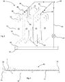
- FIG 2 shows a perspective side view of a stack of heat exchanger sheets 10 shown in Figure 1 , generally designated 20.
- the heat exchanger sheets 10 are placed next to each other so that the aluminium sides of adjacent heat exchanger sheets 10 are facing each other, and so that the fabric sides of adjacent heat exchanger sheets 10 are facing each other.
- the corrugations of adjacent sheets provide vertical channels such that there are "wet channels” having fabric sides, and "dry channels” having aluminium sides.
- the gap between two heat exchanger sheets 10 to form a wet or dry channel is at its maximum 5mm.
- the vertical channels comprise trapezoid or rhomboid flow channels for the "wet" and "dry” air.
- adjacent sheets 10 do not require supporters to form these trapezoid or rhomboid flow channels, which avoids a restriction to the air flow.
- Such an arrangement of adjacent sheets 10 stops moisture transfer between adjacent channels, and means that only heat transfer can happen between adjacent "wet” or “dry” air channels, also which provides an overall improved operation of the heat exchanger sheets 10.
- each heat exchanger sheet 10 comprise inlet and outlet regions respectively. Such flat parts of the heat exchanger sheets 10 permit ready air and water distribution within the channels of the stack of heat exchanger sheets 20.
- FIG 3 is a schematic perspective view of four sheets of the apparatus 20 of Figure 2 , generally designated 30.
- like features to the arrangements of Figure 2 are shown with like reference numerals.
- four heat exchanger sheets 10 are shown with the corrugations omitted for clarity.
- Surfaces of two of the heat exchanger sheets 10 having fabric on them are shown at 32 (i.e. the fabric 32 is on one side of each sheet 10).
- Aluminium surfaces of two of the heat exchanger sheets 10 are shown at 34 (i.e. the aluminium surface 34 is one side of each sheet 10).
- the fabric 32 of a surface of one sheet 10 faces the fabric 32 of a surface of another sheet 10.
- the aluminium surface 34 of one sheet 10 faces the aluminium surface 34 of another sheet 10.
- a water reservoir 36 having a water level 38.
- the water reservoir is filled from a supply of water 40, which may be tap water.
- a pump 42 transfers water from the water reservoir 36 along conduit 44 to two water ducts 46 at the top of the two wet channels. Water 46 from the waters ducts 46 wets the fabric 32 on each heat exchanger sheet 10, and the fibres of the fabric with the wetting agent help to spread moisture on the fabric 32 and enlarge the wetted area, which promotes evaporation.
- a valve device (not shown) may be provided so that the supply of water 30 is shut off when the reservoir water is at a certain level.
- the ambient intake air 22 is drawn into a dry channel by a fan (not shown).
- the intake air is then split into two streams whereby one stream 50 passes into the through holes 18 and the other stream exits as the cool product outlet air 24.
- the stream 50 then enters the two wet channels as shown at 52 where it causes water to evaporate from the fabric.
- the stream 50 also absorbs the heat transported from the dry channel and receives the moisture evaporated from the wet channel surface, i.e. the fabric 32. It will be understood that the fabric 32 promotes high evaporation due to the fibres and wetting agent thereof. It will be appreciated that a top of each wet chamber is closed so that the air cannot escape from the top of each wet channel and is forced downwards as shown at 52.
- the working air and water discharge are shown at 26.
- Such an arrangement may be termed a counter flow heat exchanger whereby inlet ambient air 22 passes in one direction (i.e. upwards) on one side of a sheet 10, and working air and water 26 pass in another direction (i.e. downwards) on another side of the sheet 10. It will be understood that the inlet ambient air 22 passes upwards in a "dry channel”, and the working air and water 26 pass downwards in a "wet channel”. With such an arrangement each of four corrugated heat exchanger sheets 10 works as a heat transfer plate with an increased heat transfer area. The air discharged at 26 is hot and humid.
- the air 22 travels along the dry channels of the stack where it loses heat and becomes colder due to the established temperature difference between the dry and wet sides of the sheets 10 caused by the water evaporation on the wet surface.
- the corrugated region provides an increased heat and mass transfer area between the air 22 and the air 26.
- the four sheets 10 are only a part of the stack of heat exchanger sheets 10, and the four sheets of Fig 3 are a small working unit of the apparatus. In practice the four-sheet unit would be repeated several times in a stack of heat exchanger sheets 10.
- a controller (not shown) is coupled to the water supply system, and is configured for intermittently operating the water supply system for the application of water to the fabric to maintain the fabric in a moist condition.
- the controller is also configured to recirculate water to the heat exchanger apparatus from the water reservoir 36, which may also be termed a water sump.
- FIG 4 is a cross section across the heat exchanger sheet shown in Figure 1 .
- the corrugated surface has in cross-section a profile of a periodic waveform.
- a periodic waveform may be quasi sinusoidal, triangular or other.
- An irregular or regular corrugated surface may be used.
- the corrugated surface has a horizontal dimension W, in the direction transverse to the direction of extension of corrugations therein, of 300-400 mm, 325-375 mm, or, in a preferred embodiment, 348 mm.
- the heat exchanger sheets 10 may have side strips 59, i.e. at the edges of the sheet 10, that are 6 mm wide, thereby facilitating mounting/fixing of the sheets in a stack.
- the corrugations are chosen to be of a particular dimension to promote air flow.
- T i.e. wavelength
- the periodic waveform may have an amplitude 2A of 4-6 mm, 4.5-5.5 mm or, in a preferred embodiment, 5 mm.
- the corrugations are 2.5 mm deep and 5.8 mm wide from the plane of the sheet 10. It has been found by the inventors that corrugations of these dimensions produce channels that are particularly effective in enhancing heat exchanger efficiency.
- Figure 4 also shows that the corrugations intersect the plane of the heat exchanger apparatus at an angle to that plane of 50 degrees, and the angle may be between 46-54 degrees, or in a preferred embodiment 48-52 degrees.
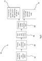
- Figure 5 shows steps of a method according to an embodiment of the invention, generally designated 60. It will be appreciated that the steps may be performed in a different order, and may not necessarily be performed in the order shown in Figure 5 .
- a plurality of heat exchanger sheets 10 are provided; this may involve tens or hundreds of heat exchanger sheets 10. Then, the heat exchanger sheets 10 are formed into a stack or heat exchanger apparatus at step 64. As part of a cooling system as hereinbefore described, a water supply system (including sump, conduits etc.) is provided, at step 66. Thereafter, the cooling system is operated at 68.
- a water supply system including sump, conduits etc.
- the method 60 may comprise the step 70 and/or the step 72.
- Step 70 comprises receiving water from the stack into the water sump and recirculating water back to the stack from the water sump. It has been found by the inventors that with this small amount of water supply, the water can be directly provided from a water tap, while the circulation pump need only be activated when the bottom water tank is full. This can significantly reduce the operational time of the pump and thus, minimise its power consumption.
- Step 72 comprises intermittently operating the water supply system for the application of water to the fabric. It has further been found by the inventors that water supply towards the wet surfaces of the heat exchanging sheets 10 should not be run continuously; instead, it should be run intermittently, for example for 20 seconds during each ten minutes of operation. This method can create a saturated wet surface over the operational period, while preventing the formation of a water film above the wet surface, which can cause a negative effect upon the water evaporation.
- the heat exchanger sheet 10 being corrugated over an upper region 14 thereof, the lower portion 16 being substantially flat and the portion 15 above the upper region 14 also being substantially flat.
- the heat exchanger sheet 10 may be corrugated over substantially the entire surface thereof. It will be understood that the area of the corrugated region 14 relative to the area of the heat exchanger sheet 10, or the area of the flat regions 15, 16 may depend on the configuration of the heat exchanger apparatus, and the skilled person will know the requirements for determining the area of the corrugated region 14 and/or flat regions 15, 16.
- the corrugated surface comprises corrugations over a first portion 14 of the one surface of the heat exchanger sheet 10, and the fabric covers at least a second portion 21 (see Fig. 1 ) of the one surface, such that the second portion 21 at least overlaps the first portion 14.
- the second portion 21 shown in Figure 2 is for illustrative purposes only, and the amount of overlap between the first portion 14 and the second portion 21 may be larger than shown.
- the corrugated surface comprises corrugations over a first portion 14 of the one surface of the heat exchanger sheet 10, and the fabric covers at least a second portion 12 of the one surface, the first portion 14 being fully contained within the second portion 12 (see Fig. 1 ).
Landscapes
- Engineering & Computer Science (AREA)
- Mechanical Engineering (AREA)
- General Engineering & Computer Science (AREA)
- Physics & Mathematics (AREA)
- Thermal Sciences (AREA)
- Heat-Exchange Devices With Radiators And Conduit Assemblies (AREA)
Priority Applications (2)
| Application Number | Priority Date | Filing Date | Title |
|---|---|---|---|
| EP21183425.4A EP3907462B1 (en) | 2016-10-13 | 2017-10-11 | Heat exchanger apparatus |
| PL17781496T PL3526537T3 (pl) | 2016-10-13 | 2017-10-11 | Urządzenie wymiennika ciepła |
Applications Claiming Priority (2)
| Application Number | Priority Date | Filing Date | Title |
|---|---|---|---|
| GBGB1617362.7A GB201617362D0 (en) | 2016-10-13 | 2016-10-13 | Heat exchanger apparatus |
| PCT/EP2017/075939 WO2018069393A1 (en) | 2016-10-13 | 2017-10-11 | Heat exchanger apparatus |
Related Child Applications (2)
| Application Number | Title | Priority Date | Filing Date |
|---|---|---|---|
| EP21183425.4A Division-Into EP3907462B1 (en) | 2016-10-13 | 2017-10-11 | Heat exchanger apparatus |
| EP21183425.4A Division EP3907462B1 (en) | 2016-10-13 | 2017-10-11 | Heat exchanger apparatus |
Publications (2)
| Publication Number | Publication Date |
|---|---|
| EP3526537A1 EP3526537A1 (en) | 2019-08-21 |
| EP3526537B1 true EP3526537B1 (en) | 2021-08-18 |
Family
ID=57680907
Family Applications (2)
| Application Number | Title | Priority Date | Filing Date |
|---|---|---|---|
| EP17781496.9A Active EP3526537B1 (en) | 2016-10-13 | 2017-10-11 | Heat exchanger apparatus |
| EP21183425.4A Active EP3907462B1 (en) | 2016-10-13 | 2017-10-11 | Heat exchanger apparatus |
Family Applications After (1)
| Application Number | Title | Priority Date | Filing Date |
|---|---|---|---|
| EP21183425.4A Active EP3907462B1 (en) | 2016-10-13 | 2017-10-11 | Heat exchanger apparatus |
Country Status (9)
| Country | Link |
|---|---|
| US (2) | US11448464B2 (pl) |
| EP (2) | EP3526537B1 (pl) |
| CN (2) | CN113701530A (pl) |
| CY (1) | CY1124823T1 (pl) |
| ES (2) | ES2929701T3 (pl) |
| GB (1) | GB201617362D0 (pl) |
| PL (2) | PL3907462T3 (pl) |
| PT (2) | PT3907462T (pl) |
| WO (1) | WO2018069393A1 (pl) |
Families Citing this family (2)
| Publication number | Priority date | Publication date | Assignee | Title |
|---|---|---|---|---|
| CN111928718B (zh) * | 2019-07-15 | 2022-10-18 | 德州贝诺风力机械设备有限公司 | 填料片及填料模块和冷却塔 |
| EP4505120A1 (en) * | 2022-04-05 | 2025-02-12 | Ecolab USA, Inc. | Method of enhancing performance of a porous evaporative media |
Family Cites Families (29)
| Publication number | Priority date | Publication date | Assignee | Title |
|---|---|---|---|---|
| US2633007A (en) * | 1948-11-19 | 1953-03-31 | Stator Company | Injector type refrigerating system |
| BE627856A (pl) * | 1962-02-13 | |||
| JPS5572797A (en) | 1978-11-22 | 1980-05-31 | Mitsubishi Electric Corp | Total heat exchanger |
| US4758385A (en) * | 1987-06-22 | 1988-07-19 | Norsaire Systems | Plate for evaporative heat exchanger and evaporative heat exchanger |
| JP3080679B2 (ja) * | 1991-04-18 | 2000-08-28 | 株式会社テクノ菱和 | 冷却塔 |
| US5873256A (en) * | 1994-07-07 | 1999-02-23 | Denniston; James G. T. | Desiccant based humidification/dehumidification system |
| AUPM777294A0 (en) | 1994-08-30 | 1994-09-22 | William Allen Trusts Pty Ltd | Spaced evaporative wicks within an air cooler |
| CA2283089C (en) | 1999-05-10 | 2004-05-25 | Mitsubishi Denki Kabushiki Kaisha | Heat exchanger and method for preparing it |
| US7101612B2 (en) | 2000-05-04 | 2006-09-05 | Kimberly Clark Worldwide, Inc. | Pre-moistened wipe product |
| US6497107B2 (en) * | 2000-07-27 | 2002-12-24 | Idalex Technologies, Inc. | Method and apparatus of indirect-evaporation cooling |
| WO2002027254A2 (en) | 2000-09-27 | 2002-04-04 | Idalex Technologies, Inc. | Method and plate apparatus for dew point evaporative cooler |
| US6656361B1 (en) * | 2000-10-15 | 2003-12-02 | Osmotek, Inc. | Membrane assisted evaporation process and device for brine concentration |
| CN1421519A (zh) | 2001-11-23 | 2003-06-04 | 吕秀娟 | 薄片状卫生洗涤用品、制造方法及其用途 |
| US20050218535A1 (en) | 2002-08-05 | 2005-10-06 | Valeriy Maisotsenko | Indirect evaporative cooling mechanism |
| US20040061245A1 (en) | 2002-08-05 | 2004-04-01 | Valeriy Maisotsenko | Indirect evaporative cooling mechanism |
| GB0324348D0 (en) | 2003-10-17 | 2003-11-19 | Oxycom Bv | Heat exchange laminate |
| EP1668297A1 (en) * | 2003-08-20 | 2006-06-14 | Oxycell Holding B.V. | Heat exchange element |
| DE10357307A1 (de) * | 2003-12-05 | 2005-07-14 | 2H Kunststoff Gmbh | Kontaktkörper, insbesondere für einen Verdunstungsbefeuchter, und Verfahren zur Herstellung eines Kontaktkörpers |
| US7501011B2 (en) * | 2004-11-09 | 2009-03-10 | Multisorb Technologies, Inc. | Humidity control device |
| TWI276768B (en) * | 2005-01-03 | 2007-03-21 | Taiwan Textile Res Inst | Heat exchange structure with at least three different airflow direction |
| JP4975970B2 (ja) | 2005-01-21 | 2012-07-11 | 日本エクスラン工業株式会社 | 収着式熱交換モジュールおよびその製法 |
| US20070141936A1 (en) | 2005-12-15 | 2007-06-21 | Bunyard William C | Dispersible wet wipes with improved dispensing |
| US7824766B2 (en) * | 2007-11-20 | 2010-11-02 | Energy Wall, Llc | Sorption paper and method of producing sorption paper |
| FR2925954B1 (fr) * | 2007-12-27 | 2015-03-13 | Armines Ass Pour La Rech Et Le Dev Des Methodes Et Processus Ind | Systeme de refroidissement d'un melange psychrometrique par couplage d'une unite de condensation et d'une unite d'evaporation |
| AU2009283776A1 (en) * | 2008-08-18 | 2011-08-18 | Hmx Systems Private Limited | Direct evaporative heat exchangers, methods of manufacture thereof and applications thereof to multi-stage cooling systems |
| JP3159566U (ja) | 2010-02-26 | 2010-05-27 | 株式会社アースクリーン東北 | 間接式気化式冷却装置 |
| AU2013201234A1 (en) * | 2012-03-08 | 2013-09-26 | Ff Seeley Nominees Pty Ltd | Wetting of Evapoartive Cooler Pads |
| US10251316B1 (en) * | 2012-05-29 | 2019-04-02 | Mistbox, Inc. | Air conditioner mister, apparatus and method |
| CN104534603B (zh) * | 2015-01-23 | 2017-07-11 | 天津大学 | 内置分流结构的逆流板式露点间接蒸发冷却器及通道隔板 |
-
2016
- 2016-10-13 GB GBGB1617362.7A patent/GB201617362D0/en not_active Ceased
-
2017
- 2017-10-11 ES ES21183425T patent/ES2929701T3/es active Active
- 2017-10-11 ES ES17781496T patent/ES2895131T3/es active Active
- 2017-10-11 US US16/342,144 patent/US11448464B2/en active Active
- 2017-10-11 EP EP17781496.9A patent/EP3526537B1/en active Active
- 2017-10-11 PL PL21183425.4T patent/PL3907462T3/pl unknown
- 2017-10-11 CN CN202111061236.2A patent/CN113701530A/zh active Pending
- 2017-10-11 PL PL17781496T patent/PL3526537T3/pl unknown
- 2017-10-11 CN CN201780063494.XA patent/CN109952486A/zh active Pending
- 2017-10-11 PT PT211834254T patent/PT3907462T/pt unknown
- 2017-10-11 EP EP21183425.4A patent/EP3907462B1/en active Active
- 2017-10-11 PT PT17781496T patent/PT3526537T/pt unknown
- 2017-10-11 WO PCT/EP2017/075939 patent/WO2018069393A1/en not_active Ceased
-
2021
- 2021-10-18 CY CY20211100900T patent/CY1124823T1/el unknown
-
2022
- 2022-08-15 US US17/888,040 patent/US12104853B2/en active Active
Non-Patent Citations (1)
| Title |
|---|
| None * |
Also Published As
| Publication number | Publication date |
|---|---|
| EP3526537A1 (en) | 2019-08-21 |
| PT3907462T (pt) | 2022-11-08 |
| PL3907462T3 (pl) | 2022-11-28 |
| WO2018069393A1 (en) | 2018-04-19 |
| PT3526537T (pt) | 2021-10-27 |
| GB201617362D0 (en) | 2016-11-30 |
| CN109952486A (zh) | 2019-06-28 |
| ES2929701T3 (es) | 2022-12-01 |
| US11448464B2 (en) | 2022-09-20 |
| US20220390177A1 (en) | 2022-12-08 |
| CY1124823T1 (el) | 2022-11-25 |
| US20190257583A1 (en) | 2019-08-22 |
| EP3907462A1 (en) | 2021-11-10 |
| CN113701530A (zh) | 2021-11-26 |
| EP3907462B1 (en) | 2022-09-21 |
| ES2895131T3 (es) | 2022-02-17 |
| US12104853B2 (en) | 2024-10-01 |
| PL3526537T3 (pl) | 2021-12-27 |
Similar Documents
| Publication | Publication Date | Title |
|---|---|---|
| US6848265B2 (en) | Air conditioning system | |
| KR102060704B1 (ko) | 열 교환 매트릭스 | |
| US20110209858A1 (en) | Indirect Evaporative Cooling Apparatus | |
| KR20180129858A (ko) | 다상 판형 열교환기에 의한 공조 | |
| US12104853B2 (en) | Heat exchanger apparatus | |
| KR20200009148A (ko) | 흡습제 공기 조화 방법 및 시스템 | |
| US20080116592A1 (en) | Method and Materials for Improving Evaporative Heat Exchangers | |
| EP3473315A1 (en) | Evaporative media pad with reduced internal spacing | |
| NL2013989B1 (en) | A method of conditioning air and an air-conditioner module. | |
| JP2017190928A (ja) | 処理機および再生機 | |
| AU2005215644B2 (en) | Plate heat and mass exchanger with edge extension | |
| CN100575800C (zh) | 包括热交换元件的露点冷却器及其制造方法 | |
| CN105042726A (zh) | 一种内冷型降膜板式除湿器 | |
| HK40052392B (en) | Heat exchanger apparatus | |
| HK40052392A (en) | Heat exchanger apparatus | |
| CN210796206U (zh) | 一种平板玻璃钢化炉用供风水冷装置 | |
| HK40056211A (en) | Heat exchanger apparatus | |
| WO2016053100A2 (en) | A method of conditioning air and an air-conditioner module | |
| JP6078602B1 (ja) | 間接気化式空調装置及び間接気化式空調方法 | |
| EP3314169B1 (en) | Enthalpy-exchanging unit for reducing the influence of surface tension, enthalpy exchanger and method for producing an enthalpy-exchanging unit | |
| JP6794481B2 (ja) | 散布トレイ、三流体熱交換器、及び湿式調湿装置 | |
| JP6078609B1 (ja) | 間接気化式空調装置及び間接気化式空調方法 | |
| NL2013990B1 (en) | A heat and mass exchange module and an air conditioner. | |
| TWI429874B (zh) | 蒸發式冷卻裝置 | |
| AU2006206035B2 (en) | Method and materials for improving evaporative heat exchangers |
Legal Events
| Date | Code | Title | Description |
|---|---|---|---|
| STAA | Information on the status of an ep patent application or granted ep patent |
Free format text: STATUS: UNKNOWN |
|
| STAA | Information on the status of an ep patent application or granted ep patent |
Free format text: STATUS: THE INTERNATIONAL PUBLICATION HAS BEEN MADE |
|
| PUAI | Public reference made under article 153(3) epc to a published international application that has entered the european phase |
Free format text: ORIGINAL CODE: 0009012 |
|
| STAA | Information on the status of an ep patent application or granted ep patent |
Free format text: STATUS: REQUEST FOR EXAMINATION WAS MADE |
|
| 17P | Request for examination filed |
Effective date: 20190507 |
|
| AK | Designated contracting states |
Kind code of ref document: A1 Designated state(s): AL AT BE BG CH CY CZ DE DK EE ES FI FR GB GR HR HU IE IS IT LI LT LU LV MC MK MT NL NO PL PT RO RS SE SI SK SM TR |
|
| AX | Request for extension of the european patent |
Extension state: BA ME |
|
| DAV | Request for validation of the european patent (deleted) | ||
| DAX | Request for extension of the european patent (deleted) | ||
| STAA | Information on the status of an ep patent application or granted ep patent |
Free format text: STATUS: EXAMINATION IS IN PROGRESS |
|
| 17Q | First examination report despatched |
Effective date: 20200703 |
|
| GRAP | Despatch of communication of intention to grant a patent |
Free format text: ORIGINAL CODE: EPIDOSNIGR1 |
|
| STAA | Information on the status of an ep patent application or granted ep patent |
Free format text: STATUS: GRANT OF PATENT IS INTENDED |
|
| INTG | Intention to grant announced |
Effective date: 20210329 |
|
| RIN1 | Information on inventor provided before grant (corrected) |
Inventor name: LI, JUNMING Inventor name: FANCEY, KEVIN Inventor name: MA, XIAOLI Inventor name: XU, PENG Inventor name: ZHAO, XUDONG |
|
| GRAS | Grant fee paid |
Free format text: ORIGINAL CODE: EPIDOSNIGR3 |
|
| GRAA | (expected) grant |
Free format text: ORIGINAL CODE: 0009210 |
|
| STAA | Information on the status of an ep patent application or granted ep patent |
Free format text: STATUS: THE PATENT HAS BEEN GRANTED |
|
| AK | Designated contracting states |
Kind code of ref document: B1 Designated state(s): AL AT BE BG CH CY CZ DE DK EE ES FI FR GB GR HR HU IE IS IT LI LT LU LV MC MK MT NL NO PL PT RO RS SE SI SK SM TR |
|
| REG | Reference to a national code |
Ref country code: GB Ref legal event code: FG4D |
|
| REG | Reference to a national code |
Ref country code: CH Ref legal event code: EP |
|
| REG | Reference to a national code |
Ref country code: DE Ref legal event code: R096 Ref document number: 602017044348 Country of ref document: DE |
|
| REG | Reference to a national code |
Ref country code: IE Ref legal event code: FG4D Ref country code: AT Ref legal event code: REF Ref document number: 1422013 Country of ref document: AT Kind code of ref document: T Effective date: 20210915 |
|
| REG | Reference to a national code |
Ref country code: PT Ref legal event code: SC4A Ref document number: 3526537 Country of ref document: PT Date of ref document: 20211027 Kind code of ref document: T Free format text: AVAILABILITY OF NATIONAL TRANSLATION Effective date: 20211020 |
|
| REG | Reference to a national code |
Ref country code: SE Ref legal event code: TRGR |
|
| REG | Reference to a national code |
Ref country code: NL Ref legal event code: FP |
|
| REG | Reference to a national code |
Ref country code: GR Ref legal event code: EP Ref document number: 20210402774 Country of ref document: GR Effective date: 20211111 |
|
| REG | Reference to a national code |
Ref country code: LT Ref legal event code: MG9D |
|
| REG | Reference to a national code |
Ref country code: EE Ref legal event code: FG4A Ref document number: E021574 Country of ref document: EE Effective date: 20211022 |
|
| REG | Reference to a national code |
Ref country code: AT Ref legal event code: MK05 Ref document number: 1422013 Country of ref document: AT Kind code of ref document: T Effective date: 20210818 |
|
| PG25 | Lapsed in a contracting state [announced via postgrant information from national office to epo] |
Ref country code: RS Free format text: LAPSE BECAUSE OF FAILURE TO SUBMIT A TRANSLATION OF THE DESCRIPTION OR TO PAY THE FEE WITHIN THE PRESCRIBED TIME-LIMIT Effective date: 20210818 Ref country code: HR Free format text: LAPSE BECAUSE OF FAILURE TO SUBMIT A TRANSLATION OF THE DESCRIPTION OR TO PAY THE FEE WITHIN THE PRESCRIBED TIME-LIMIT Effective date: 20210818 Ref country code: AT Free format text: LAPSE BECAUSE OF FAILURE TO SUBMIT A TRANSLATION OF THE DESCRIPTION OR TO PAY THE FEE WITHIN THE PRESCRIBED TIME-LIMIT Effective date: 20210818 Ref country code: BG Free format text: LAPSE BECAUSE OF FAILURE TO SUBMIT A TRANSLATION OF THE DESCRIPTION OR TO PAY THE FEE WITHIN THE PRESCRIBED TIME-LIMIT Effective date: 20211118 Ref country code: LT Free format text: LAPSE BECAUSE OF FAILURE TO SUBMIT A TRANSLATION OF THE DESCRIPTION OR TO PAY THE FEE WITHIN THE PRESCRIBED TIME-LIMIT Effective date: 20210818 Ref country code: FI Free format text: LAPSE BECAUSE OF FAILURE TO SUBMIT A TRANSLATION OF THE DESCRIPTION OR TO PAY THE FEE WITHIN THE PRESCRIBED TIME-LIMIT Effective date: 20210818 Ref country code: NO Free format text: LAPSE BECAUSE OF FAILURE TO SUBMIT A TRANSLATION OF THE DESCRIPTION OR TO PAY THE FEE WITHIN THE PRESCRIBED TIME-LIMIT Effective date: 20211118 |
|
| REG | Reference to a national code |
Ref country code: ES Ref legal event code: FG2A Ref document number: 2895131 Country of ref document: ES Kind code of ref document: T3 Effective date: 20220217 |
|
| PG25 | Lapsed in a contracting state [announced via postgrant information from national office to epo] |
Ref country code: LV Free format text: LAPSE BECAUSE OF FAILURE TO SUBMIT A TRANSLATION OF THE DESCRIPTION OR TO PAY THE FEE WITHIN THE PRESCRIBED TIME-LIMIT Effective date: 20210818 |
|
| PG25 | Lapsed in a contracting state [announced via postgrant information from national office to epo] |
Ref country code: DK Free format text: LAPSE BECAUSE OF FAILURE TO SUBMIT A TRANSLATION OF THE DESCRIPTION OR TO PAY THE FEE WITHIN THE PRESCRIBED TIME-LIMIT Effective date: 20210818 |
|
| REG | Reference to a national code |
Ref country code: DE Ref legal event code: R097 Ref document number: 602017044348 Country of ref document: DE |
|
| PG25 | Lapsed in a contracting state [announced via postgrant information from national office to epo] |
Ref country code: SM Free format text: LAPSE BECAUSE OF FAILURE TO SUBMIT A TRANSLATION OF THE DESCRIPTION OR TO PAY THE FEE WITHIN THE PRESCRIBED TIME-LIMIT Effective date: 20210818 Ref country code: SK Free format text: LAPSE BECAUSE OF FAILURE TO SUBMIT A TRANSLATION OF THE DESCRIPTION OR TO PAY THE FEE WITHIN THE PRESCRIBED TIME-LIMIT Effective date: 20210818 Ref country code: RO Free format text: LAPSE BECAUSE OF FAILURE TO SUBMIT A TRANSLATION OF THE DESCRIPTION OR TO PAY THE FEE WITHIN THE PRESCRIBED TIME-LIMIT Effective date: 20210818 Ref country code: CZ Free format text: LAPSE BECAUSE OF FAILURE TO SUBMIT A TRANSLATION OF THE DESCRIPTION OR TO PAY THE FEE WITHIN THE PRESCRIBED TIME-LIMIT Effective date: 20210818 Ref country code: AL Free format text: LAPSE BECAUSE OF FAILURE TO SUBMIT A TRANSLATION OF THE DESCRIPTION OR TO PAY THE FEE WITHIN THE PRESCRIBED TIME-LIMIT Effective date: 20210818 |
|
| REG | Reference to a national code |
Ref country code: BE Ref legal event code: MM Effective date: 20211031 |
|
| PLBE | No opposition filed within time limit |
Free format text: ORIGINAL CODE: 0009261 |
|
| STAA | Information on the status of an ep patent application or granted ep patent |
Free format text: STATUS: NO OPPOSITION FILED WITHIN TIME LIMIT |
|
| PG25 | Lapsed in a contracting state [announced via postgrant information from national office to epo] |
Ref country code: MC Free format text: LAPSE BECAUSE OF FAILURE TO SUBMIT A TRANSLATION OF THE DESCRIPTION OR TO PAY THE FEE WITHIN THE PRESCRIBED TIME-LIMIT Effective date: 20210818 |
|
| 26N | No opposition filed |
Effective date: 20220519 |
|
| PG25 | Lapsed in a contracting state [announced via postgrant information from national office to epo] |
Ref country code: LU Free format text: LAPSE BECAUSE OF NON-PAYMENT OF DUE FEES Effective date: 20211011 Ref country code: BE Free format text: LAPSE BECAUSE OF NON-PAYMENT OF DUE FEES Effective date: 20211031 |
|
| PG25 | Lapsed in a contracting state [announced via postgrant information from national office to epo] |
Ref country code: SI Free format text: LAPSE BECAUSE OF FAILURE TO SUBMIT A TRANSLATION OF THE DESCRIPTION OR TO PAY THE FEE WITHIN THE PRESCRIBED TIME-LIMIT Effective date: 20210818 |
|
| P01 | Opt-out of the competence of the unified patent court (upc) registered |
Effective date: 20230329 |
|
| PG25 | Lapsed in a contracting state [announced via postgrant information from national office to epo] |
Ref country code: HU Free format text: LAPSE BECAUSE OF FAILURE TO SUBMIT A TRANSLATION OF THE DESCRIPTION OR TO PAY THE FEE WITHIN THE PRESCRIBED TIME-LIMIT; INVALID AB INITIO Effective date: 20171011 |
|
| PG25 | Lapsed in a contracting state [announced via postgrant information from national office to epo] |
Ref country code: MK Free format text: LAPSE BECAUSE OF FAILURE TO SUBMIT A TRANSLATION OF THE DESCRIPTION OR TO PAY THE FEE WITHIN THE PRESCRIBED TIME-LIMIT Effective date: 20210818 |
|
| PG25 | Lapsed in a contracting state [announced via postgrant information from national office to epo] |
Ref country code: MT Free format text: LAPSE BECAUSE OF FAILURE TO SUBMIT A TRANSLATION OF THE DESCRIPTION OR TO PAY THE FEE WITHIN THE PRESCRIBED TIME-LIMIT Effective date: 20210818 |
|
| REG | Reference to a national code |
Ref country code: CH Ref legal event code: U11 Free format text: ST27 STATUS EVENT CODE: U-0-0-U10-U11 (AS PROVIDED BY THE NATIONAL OFFICE) Effective date: 20251101 |
|
| PGFP | Annual fee paid to national office [announced via postgrant information from national office to epo] |
Ref country code: NL Payment date: 20251023 Year of fee payment: 9 |
|
| PGFP | Annual fee paid to national office [announced via postgrant information from national office to epo] |
Ref country code: PT Payment date: 20251003 Year of fee payment: 9 |
|
| PGFP | Annual fee paid to national office [announced via postgrant information from national office to epo] |
Ref country code: DE Payment date: 20251020 Year of fee payment: 9 |
|
| PGFP | Annual fee paid to national office [announced via postgrant information from national office to epo] |
Ref country code: GB Payment date: 20251028 Year of fee payment: 9 |
|
| PGFP | Annual fee paid to national office [announced via postgrant information from national office to epo] |
Ref country code: IT Payment date: 20251031 Year of fee payment: 9 |
|
| PGFP | Annual fee paid to national office [announced via postgrant information from national office to epo] |
Ref country code: FR Payment date: 20251029 Year of fee payment: 9 |
|
| PGFP | Annual fee paid to national office [announced via postgrant information from national office to epo] |
Ref country code: TR Payment date: 20251008 Year of fee payment: 9 Ref country code: GR Payment date: 20251021 Year of fee payment: 9 |
|
| PGFP | Annual fee paid to national office [announced via postgrant information from national office to epo] |
Ref country code: SE Payment date: 20251023 Year of fee payment: 9 Ref country code: CH Payment date: 20251101 Year of fee payment: 9 |
|
| PGFP | Annual fee paid to national office [announced via postgrant information from national office to epo] |
Ref country code: IE Payment date: 20251021 Year of fee payment: 9 Ref country code: CY Payment date: 20251002 Year of fee payment: 9 |
|
| PGFP | Annual fee paid to national office [announced via postgrant information from national office to epo] |
Ref country code: PL Payment date: 20251002 Year of fee payment: 9 |
|
| PGFP | Annual fee paid to national office [announced via postgrant information from national office to epo] |
Ref country code: EE Payment date: 20251020 Year of fee payment: 9 |
|
| PGFP | Annual fee paid to national office [announced via postgrant information from national office to epo] |
Ref country code: ES Payment date: 20251114 Year of fee payment: 9 |